Embed Size (px)
Citation preview

Advanced Metering Infrastructure (AMI) Program DRAFT D2 - Distribution Engineering or Operations optimize network based on data collected by the AMI system
Document: ARCHD2USECASEv15.doc SCE Author: Standard Config Page 1 of 35
Draft AMI Use Case:
D2 - Distribution Engineering or Operations optimize network based on data collected by the AMI system
04/13/06
Author: Bob Yinger

Advanced Metering Infrastructure (AMI) Program DRAFT D2 - Distribution Engineering or Operations optimize network based on data collected by the AMI system
Document: ARCHD2USECASEv15.doc SCE Author: Standard Config Page 2 of 35
Contents 1. Use Case Description............................................................................................. 4
1.1 Use Case Title ................................................................................................................................ 4 1.2 Use Case Summary........................................................................................................................ 4 1.3 Use Case Detailed Narrative .......................................................................................................... 5 1.4 Business Rules and Assumptions .................................................................................................. 6
2. Actors ..................................................................................................................... 8
3. Step by Step analysis of each Scenario ............................................................... 10 3.1 Primary Scenario: Distribution Engineering or Operations optimize network based on voltage
Root Mean Square (RMS) Variation information at the customer site. ....................................... 10 3.1.1 Steps for this scenario........................................................................................................... 10
3.2 Primary Scenario: Distribution Engineering or Operations optimize network based on harmonics
data collected by the AMI system................................................................................................ 11 3.2.1 Steps for this scenario........................................................................................................... 12
3.3 Primary Scenario: Capacitor Bank Controller (CBC) uses the AMI infrastructure to
optimize customer voltage/power ................................................................................................. 13 3.3.1 Steps for this scenario........................................................................................................... 13
3.4 Primary Scenario: Distribution Control and Monitoring System (DCMS) reconfigures
feeder after a fault. (Refer Diagram)............................................................................................. 14 3.4.1 Steps for this scenario........................................................................................................... 14
3.5 Alternate Scenario ........................................................................................................................ 17 3.5.1 Steps for this scenario........................................................................................................... 17
4. Requirements ....................................................................................................... 20 4.1 Functional Requirements.............................................................................................................. 20 4.2 Non-functional Requirements ....................................................................................................... 23

Advanced Metering Infrastructure (AMI) Program DRAFT D2 - Distribution Engineering or Operations optimize network based on data collected by the AMI system
Document: ARCHD2USECASEv15.doc SCE Author: Standard Config Page 3 of 35
4.3 Business Requirements................................................................................................................ 25 5. Use Case Models (optional) ................................................................................. 27
5.1 Information Exchange................................................................................................................... 27 5.2 Diagrams ...................................................................................................................................... 29
6. Use Case Issues .................................................................................................. 30
7. Glossary ............................................................................................................... 31
8. References........................................................................................................... 33
9. Bibliography (optional).......................................................................................... 34
Advanced Metering Infrastructure (AMI) Program DRAFT D2 - Distribution Engineering or Operations optimize network based on data collected by the AMI system
Document: ARCHD2USECASEv15.doc SCE Author: Standard Config Page 4 of 35
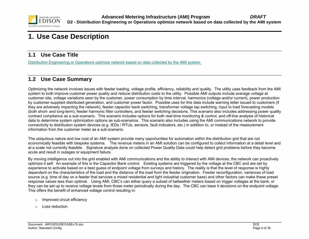
1. Use Case Description
1.1 Use Case Title Distribution Engineering or Operations optimize network based on data collected by the AMI system
1.2 Use Case Summary Optimizing the network involves issues with feeder loading, voltage profile, efficiency, reliability and quality. The utility uses feedback from the AMI system to both improve customer power quality and reduce distribution costs to the utility. Possible AMI outputs include average voltage at customer site, voltage variations seen by the customer, power consumption by time interval, harmonics (voltage and/or current), power production by customer-supplied distributed generation, and customer power factor. Possible uses for this data include warning letter issued to customers (if they are adversely impacting the network), feeder capacitor bank switching, transformer voltage tap switching, input to load forecasting models (both short- and long-term), feeder harmonic filter controllers, and feeder switching decisions. This scenario also includes addressing power quality contract compliance as a sub-scenario. This scenario includes options for both real-time monitoring & control, and off-line analysis of historical data to determine system optimization options as sub-scenarios. This scenario also includes using the AMI communications network to provide connectivity to distribution system devices (e.g. IEDs / RTUs, sensors, fault indicators, etc.) in addition to, or instead of the measurement information from the customer meter as a sub-scenario.
The ubiquitous nature and low cost of an AMI system provide many opportunities for automation within the distribution grid that are not economically feasible with bespoke systems. The revenue meters in an AMI solution can be configured to collect information at a detail level and at a scale not currently feasible. Signature analysis done on collected Power Quality Data could help detect grid problems before they become acute and result in outages or equipment failure.
By moving intelligence out into the grid enabled with AMI communications and the ability to interact with AMI devices, the network can proactively optimize it self. An example of this is the Capacitor Bank control. Existing systems are triggered by the voltage at the CBC and are set by experience to activate based on a best guess of endpoint voltage from surveys and history. The reality is that the level of response is highly dependent on the characteristics of the load and the distance of the load from the feeder origination. Feeder reconfiguration, variances of load source (e.g. time of day on a feeder that services a mixed residential and light industrial customer base) and other factors can make these preset response values less than optimal. Using AMI, CBC’s can either query a subset of bellwether meters based on trigger voltages at the bank, or they can be set up to receive voltage levels from those meter periodically during the day. The CBC can base it decisions on the endpoint voltage. This offers the benefit of enhanced voltage control resulting in:
o Improved circuit efficiency
o Loss reduction

Advanced Metering Infrastructure (AMI) Program DRAFT D2 - Distribution Engineering or Operations optimize network based on data collected by the AMI system
Document: ARCHD2USECASEv15.doc SCE Author: Standard Config Page 5 of 35
o Energy savings
By pushing the intelligence even further out in the network and leveraging the AMI communication network, the system is capable of being even more responsive. The scenario chosen for this showcases Remote Circuit switches interacting with Remote Fault Indicators to reconfigure the feeder in response to a non transient fault. This enhanced capability brings with it the need to communicate with elements of the system when their associated grid components may be de-energized, but without the ongoing communications throughout the fault, the complexities of sorting out recloser, sectionalizer and fuse timings becomes considerably more complex. With communications between energized and non energized elements the system could try several solutions before giving up, thereby reducing the number of customers affected and reducing the labor required to restore service.
On a broader scale, there are a number of places in the distribution system where monitoring information will allow for condition based maintenance (e.g. transformers, switches, capacitors). Only maintaining equipment when it is needed will result in lower capital expenditures for equipment replacement and will improve system reliability by avoiding unexpected failures. Today, the cost of communications keeps this from happening to any large extent. Implementation of a communications system for AMI will put in place a low-cost path for obtaining this information.
1.3 Use Case Detailed Narrative When measuring voltage and current at a customer site these base measurements can be used to calculate many relevant power system data values that can serve as input to existing and new power system applications.
Optimizing the behavior of the power system involves many issues related to feeder loading, voltage profiles, efficiency, reliability, quality and others. Using the information that an AMI system can provide, in addition to already existing systems, may improve the quality and efficiency of network optimization. These cases shall be investigated and defined as part of this use case.
Power system applications exist in many varieties. The most important ones that can benefit from information provided by the AMI system and that can use the AMI system to improve their performance include:
• Loss Analysis • Fault Location, Isolation and Service Restoration • Contingency Analysis • Feeder Reconfiguration • Load shedding and load curtailment • Protection Re-coordination • Voltage and VAR Control • Pre-arming of Remedial Action Schemes • Intelligent Alarm Processing • Transformer voltage regulation

Advanced Metering Infrastructure (AMI) Program DRAFT D2 - Distribution Engineering or Operations optimize network based on data collected by the AMI system
Document: ARCHD2USECASEv15.doc SCE Author: Standard Config Page 6 of 35
• Load forecasting and state estimation • Automatic feeder and capacitor bank switching • Power Quality Monitoring and Reporting • Power Quality Contract Compliance
Possible AMI outputs on behalf of these functions include:
• real time voltage • real time current • power consumption by time interval • average voltage at customer site • voltage variations seen by the customer • harmonics (voltage and/or current) • power production by customer-supplied distributed generation • customer power factor
These applications can be separated into two categories – on-line and off-line. The on-line category can be considered a classification of real-time monitoring and control. Examples of this category include alarming, volt/VAR control, and fault location. The off-line category involves evaluation of information gathered by the AMI system from a historical perspective. Applications of this type generally retrieve data from a data historian that is periodically populated with new data from the AMI system. Examples of this category include feeder optimization, load forecasting, and power quality contract compliance.
Both categories include two alternate sub-scenarios – one where the AMI communications infrastructure is utilized to communicate with equipment other than the customer’s smart meter (i.e. distribution automation and substation equipment), and the other where the functions of this use case are implemented solely from data captured by the smart meters and optionally augmented by information captured by a parallel distribution automation system (the likely scenario).
1.4 Business Rules and Assumptions • Customer in the sense of this Use Case is a customer with a grid connection < 200 kW
• The meter collects and processes usage / power quality / sensor data
• Advanced Distribution Automation and / or network optimization functions are viewed as "black boxes". The Use Case will focus on the information to provide on behalf of these functions and the information to receive from them
• The AMI system will not replace the SCADA / DMS system, it shall add on to these existing systems.

Advanced Metering Infrastructure (AMI) Program DRAFT D2 - Distribution Engineering or Operations optimize network based on data collected by the AMI system
Document: ARCHD2USECASEv15.doc SCE Author: Standard Config Page 7 of 35
• Using the information from the AMI system shall improve the existing power system applications and facilitate the creation of new ones
• Distribution operations optimizes network based on consumer metering data, and other data collected by the AMI system network

Advanced Metering Infrastructure (AMI) Program DRAFT D2 - Distribution Engineering or Operations optimize network based on data collected by the AMI system
Document: ARCHD2USECASEv15.doc SCE Author: Standard Config Page 8 of 35
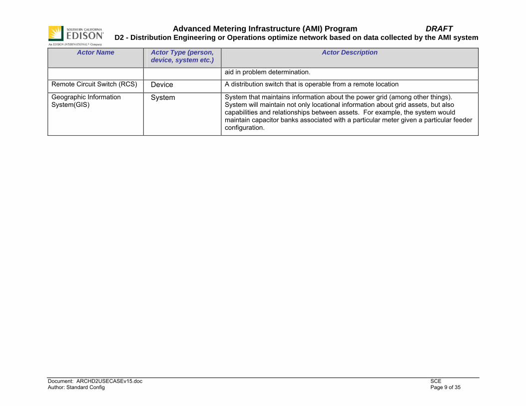
2. Actors Describe the primary and secondary actors involved in the use case. This might include all the people (their job), systems, databases, organizations, and devices involved in or affected by the Function (e.g. operators, system administrators, customer, end users, service personnel, executives, meter, real-time database, ISO, power system). Actors listed for this use case should be copied from the global actors list to ensure consistency across all use cases.
Actor Name Actor Type (person, device, system etc.)
Actor Description
Meter Device Used as sensor for voltage, current and harmonics
Power Quality Event Collector (PQEC)
System Collects PQ information from multiple sources, including the AMI system
Authorized Distribution Personnel (ADP)
Person ADP reviews and makes decisions based on the collected data
Power Quality Analyst Person Reviews PQ data
Power Quality Historian System Database to store Collected Power Quality Data and provide intelligent access to it.
Capacitor Bank Controller (CBC)
Device Device to control capacitor bank
Distribution Control and Monitoring System (DCMS)
System SCE system that is used to operate switches on distribution lines
Remote Fault Indicator (RFI) Device A device that determines if fault current has passed it and sends notice of this fault current passage to a central system
Recloser Device A “programmable” circuit breaker designed to clear transient faults by opening on overcurrent and attempting one or more times to close, each time delaying for progressively longer. The programmed delays are a balance between minimizing outages and providing adequate time for the fault path to reacquire adequate dialectic strength, thus the progressive nature.
Power Quality Analysis System
System A System used by the Power Quality Analyst, that can display Power quality information held by the PQEC in various formats and correlate it with similar data from the PQEC and other systems. A PQAS should maintain a database of common signatures that can be compared to data pulled from the AMI system and
Advanced Metering Infrastructure (AMI) Program DRAFT D2 - Distribution Engineering or Operations optimize network based on data collected by the AMI system
Document: ARCHD2USECASEv15.doc SCE Author: Standard Config Page 9 of 35
Actor Name Actor Type (person, device, system etc.)
Actor Description
aid in problem determination.
Remote Circuit Switch (RCS) Device A distribution switch that is operable from a remote location
Geographic Information System(GIS)
System System that maintains information about the power grid (among other things). System will maintain not only locational information about grid assets, but also capabilities and relationships between assets. For example, the system would maintain capacitor banks associated with a particular meter given a particular feeder configuration.

Advanced Metering Infrastructure (AMI) Program DRAFT D2 - Distribution Engineering or Operations optimize network based on data collected by the AMI system
Document: ARCHD2USECASEv15.doc SCE Author: Standard Config Page 10 of 35
3. Step by Step analysis of each Scenario Describe steps that implement the scenario. The first scenario should be classified as either a “Primary” Scenario or an “Alternate” Scenario by starting the title of the scenario with either the work “Primary” or “Alternate”. A scenario that successfully completes without exception or relying heavily on steps from another scenario should be classified as Primary; all other scenarios should be classified as “Alternate”. If there is more than one scenario (set of steps) that is relevant, make a copy of the following section (all of 3.1, including 3.1.1 and tables) and fill out the additional scenarios.
3.1 Primary Scenario: Distribution Engineering or Operations optimize network based on voltage Root Mean Square (RMS) Variation information at the customer site.
Triggering Event Primary Actor Pre-Condition Post-Condition
(Identify the name of the event that start the scenario)
(Identify the actor whose point-of-view is primarily used to describe the steps)
(Identify any pre-conditions or actor states necessary for the scenario to start)
(Identify the post-conditions or significant results required to consider the scenario
complete)
Occurrence of voltage sag Authorized Distribution Personnel (ADP)
Voltage is within tolerance levels Voltage is within tolerance levels
3.1.1 Steps for this scenario Describe the normal sequence of events that is required to complete the scenario.
Step # Actor Description of the Step Additional Notes
# What actor, either primary or secondary is responsible for the activity in this step?
Describe the actions that take place in this step. The step should be described in active, present tense.
Elaborate on any additional description or value of the step to help support the descriptions. Short notes on architecture challenges, etc. may also be noted in this column..

Advanced Metering Infrastructure (AMI) Program DRAFT D2 - Distribution Engineering or Operations optimize network based on data collected by the AMI system
Document: ARCHD2USECASEv15.doc SCE Author: Standard Config Page 11 of 35
Step # Actor Description of the Step Additional Notes
1 RMS Voltage Variation (e.g. a sag in this scenario) occurs at
the customer site. Triggering event
2 Meter Meter detects that voltage has gone below threshold (90 %)
for a certain period of time.
3 Meter Meter will report basic RMS Variation information to the
Power Quality Event Collector(PQEC) (within certain period
of time)
4 PQEC PQEC sends notification to Authorized Distribution
Personnel (ADP) depending on the type of event.
5 ADP ADP queries meter to extract detailed information about the
RMS Variation.
6 PQEC PQEC retrieves stored RMS Variation information from the
meter before its memory is full.
7 Power Quality analyst Periodically a Power Quality analyst will compare the
recorded data to the reference or baseline..
8 ADP Based on the analysis of the data, the distribution operations can optimize the network.
3.2 Primary Scenario: Distribution Engineering or Operations optimize network based on harmonics data collected by the AMI system.

Advanced Metering Infrastructure (AMI) Program DRAFT D2 - Distribution Engineering or Operations optimize network based on data collected by the AMI system
Document: ARCHD2USECASEv15.doc SCE Author: Standard Config Page 12 of 35
Triggering Event Primary Actor Pre-Condition Post-Condition
(Identify the name of the event that start the scenario)
(Identify the actor whose point-of-view is primarily used to describe the steps)
(Identify any pre-conditions or actor states necessary for the scenario to start)
(Identify the post-conditions or significant results required to consider the scenario
complete)
Occurrence of high harmonic level (voltage or current)
Authorized Distribution Personnel (ADP)
Harmonic level (voltage or current are under alert threshold
Harmonic level (voltage or current are under alert threshold
3.2.1 Steps for this scenario Describe the normal sequence of events that is required to complete the scenario.
Step # Actor Description of the Step Additional Notes
# What actor, either primary or secondary is responsible for the activity in this step?
Describe the actions that take place in this step. The step should be described in active, present tense.
Elaborate on any additional description or value of the step to help support the descriptions. Short notes on architecture challenges, etc. may also be noted in this column..
1 High Harmonic voltage / current level present at the
customer site. Triggering event
2 Meter Meter detects harmonics in voltage/current at the customer
site.
3 ADP Authorized Distribution Personnel (ADP) queries meter to
extract detailed harmonics information.
4 PQEC PQEC retrieves stored harmonic information from the meter
before its memory is full.
5 Power Quality analyst Periodically a Power Quality analyst will compare the
recorded data to the reference or baseline.

Advanced Metering Infrastructure (AMI) Program DRAFT D2 - Distribution Engineering or Operations optimize network based on data collected by the AMI system
Document: ARCHD2USECASEv15.doc SCE Author: Standard Config Page 13 of 35
Step # Actor Description of the Step Additional Notes
6 ADP Based on the analysis of the data, the distribution operations
can optimize the network.
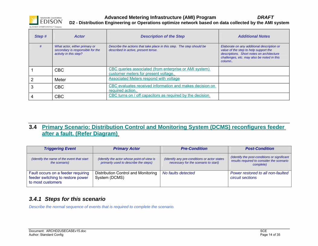
3.3 Primary Scenario: Capacitor Bank Controller (CBC) uses the AMI infrastructure to optimize customer voltage/power
Triggering Event Primary Actor Pre-Condition Post-Condition
(Identify the name of the event that start the scenario)
(Identify the actor whose point-of-view is primarily used to describe the steps)
(Identify any pre-conditions or actor states necessary for the scenario to start)
(Identify the post-conditions or significant results required to consider the scenario
complete)
Voltage on distribution feeder varies as the day progresses
Cap Bank Controller (CBC) Voltage variations on distribution feeder are within acceptable limits
Voltage variations on distribution feeder are within acceptable limits
3.3.1 Steps for this scenario Describe the normal sequence of events that is required to complete the scenario.
Advanced Metering Infrastructure (AMI) Program DRAFT D2 - Distribution Engineering or Operations optimize network based on data collected by the AMI system
Document: ARCHD2USECASEv15.doc SCE Author: Standard Config Page 14 of 35
Step # Actor Description of the Step Additional Notes
# What actor, either primary or secondary is responsible for the activity in this step?
Describe the actions that take place in this step. The step should be described in active, present tense.
Elaborate on any additional description or value of the step to help support the descriptions. Short notes on architecture challenges, etc. may also be noted in this column..
1 CBC CBC queries associated (from enterprise or AMI system) customer meters for present voltage.
2 Meter Associated Meters respond with voltage 3 CBC CBC evaluates received information and makes decision on
required action.
4 CBC CBC turns on / off capacitors as required by the decision
3.4 Primary Scenario: Distribution Control and Monitoring System (DCMS) reconfigures feeder after a fault. (Refer Diagram)
Triggering Event Primary Actor Pre-Condition Post-Condition
(Identify the name of the event that start the scenario)
(Identify the actor whose point-of-view is primarily used to describe the steps)
(Identify any pre-conditions or actor states necessary for the scenario to start)
(Identify the post-conditions or significant results required to consider the scenario
complete)
Fault occurs on a feeder requiring feeder switching to restore power to most customers
Distribution Control and Monitoring System (DCMS)
No faults detected Power restored to all non-faulted circuit sections
3.4.1 Steps for this scenario Describe the normal sequence of events that is required to complete the scenario.

Advanced Metering Infrastructure (AMI) Program DRAFT D2 - Distribution Engineering or Operations optimize network based on data collected by the AMI system
Document: ARCHD2USECASEv15.doc SCE Author: Standard Config Page 15 of 35
Step # Actor Description of the Step Additional Notes
# What actor, either primary or secondary is responsible for the activity in this step?
Describe the actions that take place in this step. The step should be described in active, present tense.
Elaborate on any additional description or value of the step to help support the descriptions. Short notes on architecture challenges, etc. may also be noted in this column..
1 Fault on Feeder between RFI 1 and RFI 2 Triggering event 2 RFI RFI 1 reports fault to DCMS. DCMS actor 3 Recloser Station recloser 2 opens. 4 RCS RCS 2 reports loss of voltage to DCMS 5 Recloser 1st reclose on recloser 2 occurs after 15 sec and opens 6 RFI RFI 1 reports fault (again) 7 RCS RCS 2 opens after 30 sec and reports status. 8 Recloser Recloser 2 closes after 40 sec (55 sec after fault) and opens
again and locks out.
9 ADP Operator at DCMS decides to close RCS3 (direct operate) based on
• Historical loading (pre fault conditions) • Expected load after restoration
Also DCMS is an actor

Advanced Metering Infrastructure (AMI) Program DRAFT D2 - Distribution Engineering or Operations optimize network based on data collected by the AMI system
Document: ARCHD2USECASEv15.doc SCE Author: Standard Config Page 16 of 35
Feeder 2 Feeder 1
Recloser 2
RFI 1 Pole switch - PS
RCS 2
A
RFI 2
RFI 3 PS
RCS 3
N
RCS 1
A
RFI 4
PS
Recloser 1
Substation

Advanced Metering Infrastructure (AMI) Program DRAFT D2 - Distribution Engineering or Operations optimize network based on data collected by the AMI system
Document: ARCHD2USECASEv15.doc SCE Author: Standard Config Page 17 of 35
3.5 Alternate Scenario RCS devices autonomously reconfigure after a fault. (Refer Diagram)
Triggering Event Primary Actor Pre-Condition Post-Condition
(Identify the name of the event that start the scenario)
(Identify the actor whose point-of-view is primarily used to describe the steps)
(Identify any pre-conditions or actor states necessary for the scenario to start)
(Identify the post-conditions or significant results required to consider the scenario
complete)
Feeder reconfiguration does not require intervention of DCMS but can be accomplished automatically by switches in the area using the AMI communications system
Recloser No fault detected
RCS,RFI devices require coincident grid topology and associated devices
RCS devices are programmed to insure fault free voltage on both sides
Scenario does not assume new intelligence or communication capability in recloser
Feeder reconfiguration complete
3.5.1 Steps for this scenario Describe the normal sequence of events that is required to complete the scenario.
Step # Actor Description of the Step Additional Notes
# What actor, either primary or secondary is responsible for the activity in this step?
Describe the actions that take place in this step. The step should be described in active, present tense.
Elaborate on any additional description or value of the step to help support the descriptions. Short notes on architecture challenges, etc. may also be noted in this column..

Advanced Metering Infrastructure (AMI) Program DRAFT D2 - Distribution Engineering or Operations optimize network based on data collected by the AMI system
Document: ARCHD2USECASEv15.doc SCE Author: Standard Config Page 18 of 35
Step # Actor Description of the Step Additional Notes
RCS 1, 2 and 3 exchange information and automatically decide on reconfiguration.
Refer to diagram and scenario 3.4.1. The collaborative nature of the scenario makes it difficult to lay out in a stepwise fashion with any definitive precedence of operations or certain assignment of responsibilities. This particular sequence only represents one of many possible. For example, this scenario assumes the recloser continues to operate in a “dumb” fashion with no coordination with other system elements. The particular sequence chosen here assumes each RCS responds to requests from other devices, but only initiates action based on self interest (in other words, to maintain its desired state of energized, fault free on both sides)
1 Fault on Feeder between RFI 1 and RFI 2 Triggering event 2 RFI RFI 1 reports fault to RCS 1,RCS 2 and RCS 3. 3 Recloser Station recloser opens. 4 RCS RCS 2 reports loss of voltage to RCS-1 and RCS-3 5 Recloser 1st reclose occurs after 15 sec and opens 6 RFI RFI 1 reports fault (again) to RCS1, RCS 2 and RCS 3 7 RCS RCS 2 opens after 30 sec and reports status.
8 Recloser Recloser closes after 40 sec (55 sec after fault), opens and then locks out.

Advanced Metering Infrastructure (AMI) Program DRAFT D2 - Distribution Engineering or Operations optimize network based on data collected by the AMI system
Document: ARCHD2USECASEv15.doc SCE Author: Standard Config Page 19 of 35
Step # Actor Description of the Step Additional Notes
9 RCS RCS 3 senses loss of voltage on RCS 2 segment side, requests status of RFI 3.
10 RFI RFI 3 responds with no voltage/ no fault 11 RCS RCS 3 closes and broadcasts status 12 RFI RFI 3 announces voltage/ no fault to RCS 1, RCS 2, and
RCS 3
13 RCS RCS 3 reports configuration to DCMS

Advanced Metering Infrastructure (AMI) Program DRAFT D2 - Distribution Engineering or Operations optimize network based on data collected by the AMI system
Document: ARCHD2USECASEv15.doc SCE Author: Standard Config Page 20 of 35
4. Requirements Detail the Functional, Non-functional and Business Requirements generated from the workshop in the tables below. If applicable list the associated use case scenario and step.
4.1 Functional Requirements
Functional Requirements Associated Scenario #
(if applicable)
Associated Step #
(if applicable)
The meter shall provide the voltage and load reading at the customer site to the Power Quality Event Collector.
1 2
Meter shall monitor the voltage continuously in order to detect an RMS variation according to parameters specified in standard IEEE 1159.
1 2
Meter shall provide detailed RMS Variation event data for query on demand. (See NFR 2) 1 5,6
Automatic event driven reporting of the basic RMS variation data as defined in IEEE 1159, to the Power Quality Event Collector shall be based on magnitude, duration, and direction. (per phase, aggregate)
1
RMS variation event data captured by the meter shall be retrievable from the meter even if there is a communications outage before, during, and after the event. This FR states that no data will be lost, but it does not have to be retrieved during the outage.
1
The Power Quality Event Collector shall have the capability to send notifications to Authorized Distribution Personnel (ADP) based on event type as defined in IEEE 1159. These notifications are however not considered to be critical.
1 4
Authorized Distribution Personnel (ADP) shall have the capability to query the meter and retrieve detailed RMS Variation information, as defined in IEEE 1159, both locally and from remote. Local communication has priority over remote
1 5
Authorized Distribution Personnel (ADP) shall have the capability to query the meter and retrieve detailed harmonic information as defined in IEEE 1159, both locally and from remote. Local communication has priority over remote.
2

Advanced Metering Infrastructure (AMI) Program DRAFT D2 - Distribution Engineering or Operations optimize network based on data collected by the AMI system
Document: ARCHD2USECASEv15.doc SCE Author: Standard Config Page 21 of 35
Functional Requirements Associated Scenario #
(if applicable)
Associated Step #
(if applicable)
Authorized Distribution Personnel (ADP) shall have the capability to retrieve historical RMS Variation data from the PQ historian.
The PQ Historian is the storage place for the RMS variation data (and also the harmonic data). The data should be actively available for at least 1 year and archived after that (but not lost). The data should not be destroyed until it is at least 10 years old.
1 5
Authorized Distribution Personnel (ADP) shall have the capability to retrieve historical harmonic data from the PQ historian
2 3
Meter shall measure harmonics data according to IEC 61000-4-7 and IEEE 519 for voltage and current.
2 2
The Power Quality Analysis System shall be capable of summing up the individual harmonic measurements. (Magnitude + Phase angle [sample])
2 5
The Power Quality Analysis System shall support analysis of harmonics data to build a historical baseline of harmonics
2 4
Meter shall record the harmonics data according to IEC 61000-4-7 and IEEE 519 2 2
The data retrieval for harmonics data shall be periodic 2 4
The data retrieval period for the Power Quality Event Controller (PQEC) shall be less than the history available in the meter (no lost data)
2 4
Capacitor Bank Controller obtains a list of associated meters and their communications address from an external source for the purpose of establishing communications with these meters. The external source for this information can be:
- Geographic Information System (GIS) - The Meters - Manual Configuration of the Capacitor Bank Controller
3 1
Capacitor Bank Controller shall obtain the present value of voltage from the associated meters 3 1
Capacitor Bank Controller shall obtain the Substation Capacitor Bank status for its control algorithm from an external source (most likely SCADA)
3 1
Meter shall be capable of responding to a request from an external source for present voltage 3 1

Advanced Metering Infrastructure (AMI) Program DRAFT D2 - Distribution Engineering or Operations optimize network based on data collected by the AMI system
Document: ARCHD2USECASEv15.doc SCE Author: Standard Config Page 22 of 35
Functional Requirements Associated Scenario #
(if applicable)
Associated Step #
(if applicable)
Meter shall report the following information to the Capacitor Bank Controller:
• Timestamp • Voltage
3 1
The capacitor bank control function shall not operate during power outages 3 1
Fault report from the Remote Fault Indicator (RFI) to the DCMS shall include :
• ID • Time • Fault indication • Fault magnitude
4 2
Communications from field devices (e.g. Remote Circuit Switches and Remote Fault Indicators) to the Distribution Control and Monitoring System shall be available when the power out. This communications will allow normal functions of the device to be performed. An example of why this is needed would be in the case of a remote switch used to isolate a fault at the end of a feeder after the recloser had given up on a persistent fault. Using the diagram above, this would be the case if RFI 3 had signaled and Recloser 2 had tripped. Before RCS 3 could close, RCS 2 would have to open. Without the ongoing communications with power out at some components because of the fault, the complexities of sorting out recloser, sectionalizer and fuse timings become considerably more complex. With communications between energized and non energized elements, the proper reconfiguration would be possible.
4 2
Remote Controlled Switch reports :
• ID • Time • All of its status points including status of A/C (alternating current) power on both sides of
the switch
4,5
4,9.1.1
Remote Controlled Switch shall be able to receive control from DCMS and acknowledge – See NFR 14
4 9
The reference design of the AMI System shall be modular enough to interface with devices other than meters (e.g. RFI’s, RCS’s)
4
5
2,4,6,7,9
1
The meter shall be configurable so that RMS variation events can be reported with an unsolicited message, with a daily read or not at all (this FR is related to FR3 and FR4)
1 3

Advanced Metering Infrastructure (AMI) Program DRAFT D2 - Distribution Engineering or Operations optimize network based on data collected by the AMI system
Document: ARCHD2USECASEv15.doc SCE Author: Standard Config Page 23 of 35
Functional Requirements Associated Scenario #
(if applicable)
Associated Step #
(if applicable)
Reporting of Power Quality Events by the meter can be turned On or Off locally and from remote by Power Quality Event Collector
1
2
3
2
The meter shall be configurable locally and from remote to specify which harmonic components and summary quantities (THD, HRMS, TIF) shall be stored in the meter and which ones shall be retrieved by the Power Quality Event Collector
2 4
Data for signature analysis shall be provided on demand at chosen meters and other AMI enabled data collection points – See BR1
4 2,4,6,8
4.2 Non-functional Requirements
Non-Functional Requirements Associated Scenario #
(if applicable)
Associated Step #
(if applicable)
RMS Variation detection shall follow the IEC 61000-4-30 and IEEE 1159 standards 1 2
The meter shall be capable of retaining and returning event based power quality information upon query for a minimum of 60 days after the data is captured even if there is no communications with the meter over the 60 day period. The EPRI Distribution Power Quality Report, defines the statistics for the number of events within this period. Information will not automatically be retrieved from each meter installed so having 60 days of detailed history available within the AMI system will allow sufficient time for it to be retrieved if it is required. This data would be required if there was a customer complaint or other system problems observed. Once the data has been retrieved from the meter, the meter can delete the data from its memory.
1 6
Harmonics data collection shall follow IEC 61000-4-30 (Class B and IEEE 519) standards 2 2

Advanced Metering Infrastructure (AMI) Program DRAFT D2 - Distribution Engineering or Operations optimize network based on data collected by the AMI system
Document: ARCHD2USECASEv15.doc SCE Author: Standard Config Page 24 of 35
Non-Functional Requirements Associated Scenario #
(if applicable)
Associated Step #
(if applicable)
Harmonic level to be measured and stored shall range up to the 9th or 15th 2 2
Meter shall store the harmonics data for a period ranging from 1 – 7 days.
This storage period is related to the data retrieval period (NFR6). If the data retrieval period is daily, data only needs to be stored for 1 day. If the retrieval period is longer, the storage needs to be longer. Once the data has been retrieved from the meter, the meter can delete the data from its memory.
2 4
The data retrieval period for the Power Quality Event Controller (PQEC) shall be less than the history available in the meter
2 4
Present voltage of selected meters associated with the CBC is needed (at the CBC) every 15 min
3 1
All meters associated with a CBC will send present voltage with a timestamp spread of no more than 5 seconds between the reads.
(System remains in known state during this cycle)
3 1
Timestamp difference between reports from different meters shall be less than 5 sec. (system remains in known state during this cycle)
3 1
The system will support up to 100 meters per Capacitor Bank Controller (typically less than 10) 3 1
At least 50% of the meters associated with a CBC shall respond 3 1
The AMI system shall support 10000-12000 Capacitor Bank Controllers 3 1
Security of the communications shall be at a level consistent with control (switch operation) 3
4
1
9
Fault report from the meter shall be at DCMS in less than 5 sec (time of fault to annunciation) 4 2,4,6,8
Communication to DCMS shall be available for at least 8 hrs with power out. 4 2,4,6,8,9
Messages from the meter to the Power Quality Event Collector shall be delivered at least 99.9% of the time over the course of a year. Loss of a message will result in reduced functionality.
1
2
3,6
4
Number of devices communicating for the purpose of carrying out scenario 4 is 6-8 per circuit 4

Advanced Metering Infrastructure (AMI) Program DRAFT D2 - Distribution Engineering or Operations optimize network based on data collected by the AMI system
Document: ARCHD2USECASEv15.doc SCE Author: Standard Config Page 25 of 35
Non-Functional Requirements Associated Scenario #
(if applicable)
Associated Step #
(if applicable)
The AMI System shall be able to handle up to 12 circuits exercising scenario 4 simultaneously 4
The message latency for unsolicited messages sent from the meter to the Power Quality Event Collector shall be better than 5 minutes
1 3
4.3 Business Requirements Business Requirement Associated
Scenario #
(if applicable)
Associated Step #
(if applicable)
Signature analysis collected from Power Quality Data (oscillography from RMS variations) could help detect a problem before it occurs. – See FR33
1,2
The RMS variation data collected by the meter at the customer site shall be used to detect the origin of an RMS variation (Customer side or Network side).
1
Replacing the existing communications infrastructure for distribution automation with an AMI infrastructure allows for the integration of multiple communication infrastructures into a single one and avoiding parallel operation of various communications infrastructures avoids cost.
3, 4, 5
Use of Service Point present voltage for the purpose of enhanced voltage control could result in
• Improved circuit efficiency • Loss reduction • Energy savings
3
Replacing the existing radio (Utilinet) communication network implies replacing processing functions in the present radios which will add cost
3, 4, 5
Low cost RFIs would facilitate deployment of more RFIs. This would reduce restoration time which improves reliability statistics. Reduction in cost is also envisioned by sending people to the right location more quickly.
3

Advanced Metering Infrastructure (AMI) Program DRAFT D2 - Distribution Engineering or Operations optimize network based on data collected by the AMI system
Document: ARCHD2USECASEv15.doc SCE Author: Standard Config Page 26 of 35
Business Requirement Associated Scenario #
(if applicable)
Associated Step #
(if applicable)
The AMI communications architecture can be used for asset management and monitoring information from the distribution system. This allows for the implementation of Condition Based Maintenance which will result in lower capital expenditures for equipment replacement and it improves system reliability by avoiding unexpected failures
1, 2, 3, 4, 5
Advanced Metering Infrastructure (AMI) Program DRAFT D2 - Distribution Engineering or Operations optimize network based on data collected by the AMI system
Document: ARCHD2USECASEv15.doc SCE Author: Standard Config Page 27 of 35
5. Use Case Models (optional) This section is used by the architecture team to detail information exchange, actor interactions and sequence diagrams
5.1 Information Exchange For each scenario detail the information exchanged in each step
This information exchange matrix supports scenario 3.1. It may be applied to other RMS variation scenarios as well.
Scenario # Step #, Step Name Information Producer Information Receiver
Name of information exchanged
# Name of the step for this scenario. What actors are primarily responsible for Producing the information?
What actors are primarily responsible for Receiving the information?
Describe the information being exchanged
3.1 3 Meter PQEC Basic RMS Variation Information
3.1 4 PQEC ADP Variation event notification
3.1 5 Meter ADP Detailed RMS variation information
3.1 6 Meter PQEC RMS variation history information
3.1 7 PQEC Power Quality Analyst Recorded PQ data 3.1 8 ADP DCMS Optimization
commands 3.5.1 2 RFI RCS (multiple) Fault indication 3.5.1 4 RCS RCS (multiple) Loss of Voltage
Indication

Advanced Metering Infrastructure (AMI) Program DRAFT D2 - Distribution Engineering or Operations optimize network based on data collected by the AMI system
Document: ARCHD2USECASEv15.doc SCE Author: Standard Config Page 28 of 35
Scenario # Step #, Step Name Information Producer Information Receiver
Name of information exchanged
3.5.1 6 RFI RCS(multiple) Fault Indication 3.5.1 7 RCS RCS(multiple) De Energized
Status 3.5.1 9 RCS RFI Status Request 3.5.1 10 RFI RCS Status
o Fault(Y/N) o Voltage(v)
3.5.1 11 RCS DCMS,RCS(multiple) Status o Open/Close
o Voltage 3.5.1 12 RFI DCMS,RCS(multiple) Status
o Fault(Y/N) o Voltage(v)
3.5.1 13 RCS DCMS Status o Open/Close
o Voltage

Advanced Metering Infrastructure (AMI) Program DRAFT D2 - Distribution Engineering or Operations optimize network based on data collected by the AMI system
Document: ARCHD2USECASEv15.doc SCE Author: Standard Config Page 29 of 35
5.2 Diagrams The architecture team shall use this section to develop an interaction diagram that graphically describes the step-by-step actor-system interactions for all scenarios. The diagrams shall use standard UML notation. Additionally, sequence diagrams may be developed to help describe complex event flows.
The following sequence diagram supports RMS variation scenarios 3.1.1. and 3.1.2.

Advanced Metering Infrastructure (AMI) Program DRAFT D2 - Distribution Engineering or Operations optimize network based on data collected by the AMI system
Document: ARCHD2USECASEv15.doc SCE Author: Standard Config Page 30 of 35
6. Use Case Issues Capture any issues with the use case. Specifically, these are issues that are not resolved and help the use case reader understand the constraints or unresolved factors that have an impact of the use case scenarios and their realization.
Issue
Describe the issue as well as any potential impacts to the use case.
Do the security, availability, and reliability requirements (NERC/CIP) differ for Distribution Automation and AMI?

Advanced Metering Infrastructure (AMI) Program DRAFT D2 - Distribution Engineering or Operations optimize network based on data collected by the AMI system
Document: ARCHD2USECASEv15.doc SCE Author: Standard Config Page 31 of 35
7. Glossary Insert the terms and definitions relevant to this use case. Please ensure that any glossary item added to this list should be included in the global glossary to ensure consistency between use cases.
Glossary
Term Definition
RMS Variation As defined in IEEE 1159 and IEC 61000-4-30. A change in the instantaneous RMS voltage (1 cycle window calculated at least twice per cycle) outside of established nominal boundaries (specified by default as +/- 10% of declared nominal). Include voltage sags, swells, and momentary interruptions up to 1 minute in duration.
Basic RMS Variation information
time of event , magnitude, duration as defined in IEC 61000-4-30. Optionally includes RMS Variation directionality.
Detailed RMS Variation information
The instantaneous waveform during the RMS variation event and the instantaneous (1 cycle window with a 0.5 cycle update rate) RMS value for each voltage phase/leg. An example can be found in IEEE std. 1159 and is shown graphically in the following figure.
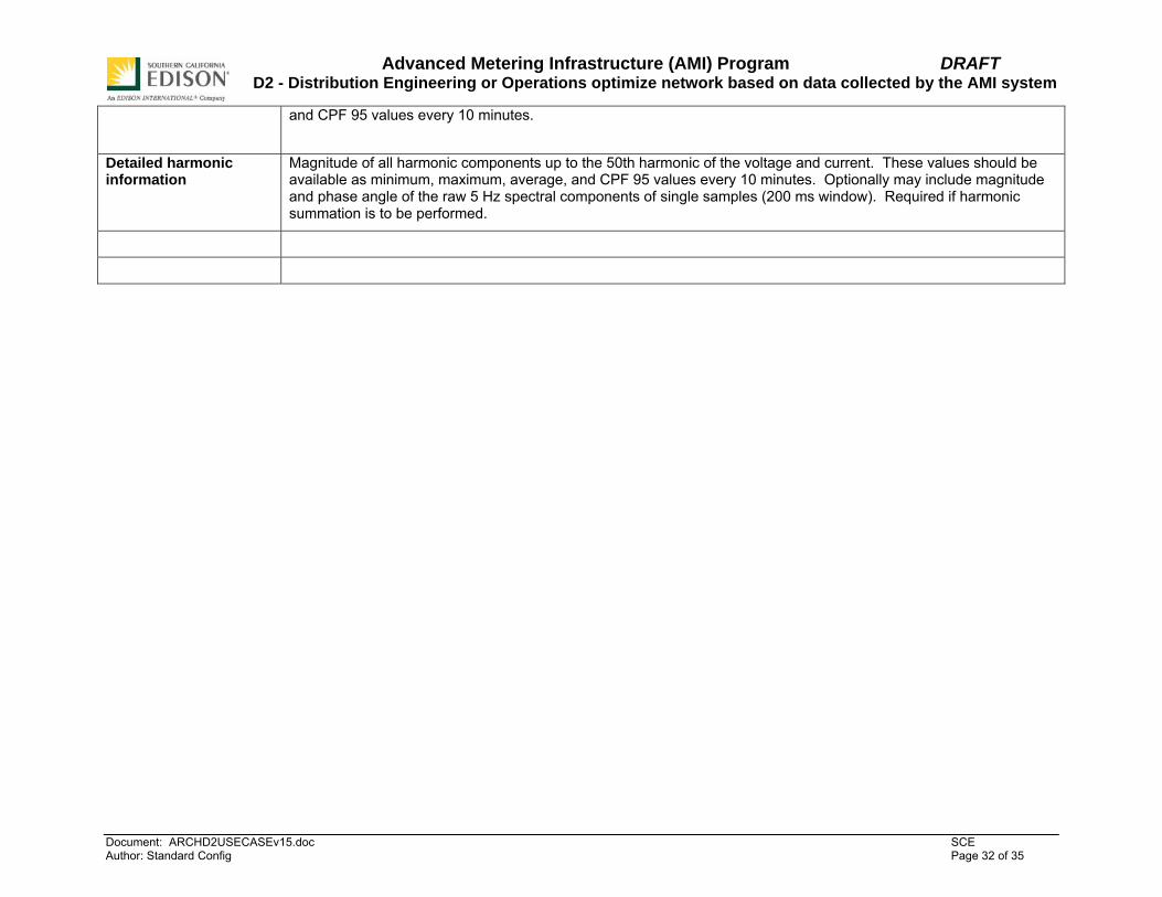
Basic harmonic information
Voltage Total Harmonic Distortion (THD) in percent as defined in IEEE 519. Also may include the RMS value of the harmonic components of the current in amps. These values should be available as minimum, maximum, average,
Advanced Metering Infrastructure (AMI) Program DRAFT D2 - Distribution Engineering or Operations optimize network based on data collected by the AMI system
Document: ARCHD2USECASEv15.doc SCE Author: Standard Config Page 32 of 35
and CPF 95 values every 10 minutes.
Detailed harmonic information
Magnitude of all harmonic components up to the 50th harmonic of the voltage and current. These values should be available as minimum, maximum, average, and CPF 95 values every 10 minutes. Optionally may include magnitude and phase angle of the raw 5 Hz spectral components of single samples (200 ms window). Required if harmonic summation is to be performed.
Advanced Metering Infrastructure (AMI) Program DRAFT D2 - Distribution Engineering or Operations optimize network based on data collected by the AMI system
Document: ARCHD2USECASEv15.doc SCE Author: Standard Config Page 33 of 35
8. References Intelligrid Use Cases D 11.2
OpenAMI Use Case #6

Advanced Metering Infrastructure (AMI) Program DRAFT D2 - Distribution Engineering or Operations optimize network based on data collected by the AMI system
Document: ARCHD2USECASEv15.doc SCE Author: Standard Config Page 34 of 35
9. Bibliography (optional) Provide a list of related reading, standards, etc. that the use case reader may find helpful.
• Paper reference from Cyrus and Thosar – University of Texas at Houston.
• Utilities Implement Intelligent Monitoring Applications to Improve Reliability --Transmission and Distribution World 2005, Mark McGranaghan, EPRI Solutions, Scott Peele, Progress Energy, and Marek Waclawiak, United Illuminating
• IEEE 519-1992 Recommended Practices and Requirements for Harmonic Control in Electrical Power Systems.
• IEEE 1159:Monitoring Electric Power Quality
o IEEE 1159.1: Guide For Recorder and Data Acquisition Requirements
o IEEE 1159.2: Power Quality Event Characterization
• IEEE P1564:Voltage Sag Indices
• IEEE 1433: Power Quality Definitions
• IEEE P1453: Voltage flicker
• IEC 61000 Electromagnetic compatibility (EMC)
o IEC 61000-2-1: Guide to electromagnetic environment for low-frequency conducted disturbances and signalling in public power supply systems
o IEC 61000-2-7: Environment - Low frequency magnetic fields in various environments
o IEC 61000-2-9: Environment - Description of HEMP environment. Radiated disturbance. Basic EMC publication
o IEC 61000-2-10: Environment - Description of HEMP environment. Conducted disturbance
o IEC 61000-3-2: Limits - Limits for harmonic current emissions (equipment input current up to and including 16 A per phase)
o IEC 61000-3-3: Limits - Limitation of voltage changes, voltage fluctuations and flicker in public low-voltage supply systems, for equipment with rated current ≤ 16 A per phase and not subject to conditional connection
o IEC 61000-3-4: Limits - Limitation of emission of harmonic currents in low-voltage power supply systems for equipment with rated current greater than 16 A
o IEC 61000-4-1: Testing and measurement techniques - Overview of IEC 61000-4 series
o IEC 61000-4-2: Testing and measurement techniques - Electrostatic discharge immunity tests. Basic EMC publication
o IEC 61000-4-3: Testing and measurement techniques - Radiated, radio-frequency, electromagnetic field immunity test
o IEC 61000-4-4: Testing and measurement techniques - Electrical fast transient/burst immunity test. Basic EMC publication
Advanced Metering Infrastructure (AMI) Program DRAFT D2 - Distribution Engineering or Operations optimize network based on data collected by the AMI system
Document: ARCHD2USECASEv15.doc SCE Author: Standard Config Page 35 of 35
o IEC 61000-4-5: Testing and measurement techniques - Surge immunity test
o IEC 61000-4-6: Testing and measurement techniques - Immunity to conducted disturbances, induced by radio-frequency fields
o IEC 61000-4-8: Testing and measurement techniques - Power frequency magnetic field immunity test. Basic EMC publication
o IEC 61000-4-9: Testing and measurement techniques - Pulse magnetic field immunity test. Basic EMC publication
o IEC 61000-4-10: Testing and measurement techniques - Damped oscillatory magnetic field immunity test. Basic EMC publication
o IEC 61000-4-12: Testing and measurement techniques - Oscillatory waves immunity test. Basic EMC publication
o IEC 61000-4-13: Testing and measurement techniques - Harmonics and interharmonics including mains signalling at A.C. power port, low frequency immunity tests
o IEC 61000-4-14: Testing and measurement techniques - Voltage fluctuation immunity test
o IEC 61000-4-15: Testing and measurement techniques - Flickermeter. Functional and design specifications. Basic EMC publication
o IEC 61000-4-16: Testing and measurement techniques - Test for immunity to conducted, common mode disturbances in the frequency range 0 Hz to 150 kHz
o IEC 61000-4-17: Testing and measurement techniques - Ripple on d.c. input power port immunity test
o IEC 61000-4-23: Testing and measurement techniques - Test methods for protective devices for HEMP and other radiated disturbances
o IEC 61000-4-24: Testing and measurement techniques - Test methods for protective devices for HEMP conducted disturbance. Basic EMC publication
o IEC 61000-4-25: Testing and measurement techniques - HEMP immunity test methods for equipment and systems
o IEC 61000-4-27: Testing and measurement techniques - Unbalance, immunity test
o IEC 61000-4-28: Testing and measurement techniques - Variation of power frequency, immunity test
o IEC 61000-4-29: Testing and measurement techniques - Testing and measurement techniques. Voltage dips, short interruptions and voltage variations on d.c. input power port immunity tests