Embed Size (px)
Citation preview
I REPORT R-1785
PROCESS D q OF D
GPO PRICE $
CFSTI PRICE(S) $ by
ANTHONY SAIA W H E . EDEIMBN
Hard copy (HC) $2 o-il Microfiche (MF)
GmRGE C. MBRSMLL SPAGe FLIGHT CENTER National Aercmautlcs & Space Administrati
Euntsville, Alabama
?,
Distribution of this report is unlimited.
UNITED SI
https://ntrs.nasa.gov/search.jsp?R=19660007822 2018-06-01T19:08:49+00:00Z

DISPOSITION XNSTRUCT IOES
Destroy th is report when it i s no longer needed. Do no t return i t to the originator.
FY)
The findings in this report are not t o be construed as an o f f i c i a l Department of the Army position unless s o designated by bthei: authorized documents.
.

, ',
' .
REPORT R- 1785
PROCESS DEVELOPMENT OF SHAPED MAGNESIUM-LITHIUM CASTINGS
ANTHONY SAIA RALPH E . EDELMAN
f o r
GEORGE C. MARSHALL SPACE FLIGHT CENTER National Aeronautics & Space Administration
Huntsvi l le , Alabama
' , / NASA Defense Purchase Request H-71508
D i s t r i b u t i o n of t h i s r epor t i s unlimited,
Pitman-Dunn Research Laboratories FRANKFORD ARSENAL
Philadelphia , Pa 19137
November 1965

FOREWORD
Thi s repor t w a s prepared a t Frankford Arsenal , P h i l a d e l p h i a , Pa. , f o r the George C. Marshal l Space F l i g h t Center of the Nat iona l Aero- n a u t i c s and Space Adminis t ra t ion, under NASA Defense Purchase Request H-71508, The work was performed a t Frankford Arsenal by Anthony S a i a and Ralph E. Edelman, under the t e c h n i c a l d i r e c t i o n of the Propuls ion and Vehicle Engineering Laboratory, Ma te r i a l s Div is ion of t he George C. Marshal l Space F l i g h t Center , with M r Herman L. Gilmore (R-P&VE- M M P MSFC) as P r o j e c t Manager.
ii

ABSTRACT
I - A process has been developed f o r s u c c e s s f u l l y c a s t i n g a number of prototype aerospace components u s ing the t e r n a r y magnesium-lithium- s i l i c o n a l l o y . These components conta ined many of the design elements a n t i c i p a t e d i n aerospace hardware of t h i s type.
It was found t h a t conventional magnesium sand foundry practice was not s a t i s f a c t o r y . A new molding material , based upon ben ton i t e - bonded g raph i t e powder, was employed. Melt ing and pouring p r a c t i c e was a l s o modified t o cope w i t h the r e a c t i v e na ture of the a l l o y .
I -
The rad iographic q u a l i t y of t he c a s t i n g s and mechanical proper- t i e s of t e s t b a r s sec t ioned from the c a s t i n g s were evaluated and found t o be s a t i s f a c t o r y and t o correspond wi th e a r l i e r experience on sepa- r a t e l y c a s t t e s t ba r s .
iii

TABLE OF CONTENTS Page
. . . . . . . . . . . . . . . . . . . . . . . . . . . . 1
. . . . . . . . . . . . . . . . . . . . . . 2
INTRODUCTION.
MATERIALS ANDMETHODS
2 C a s t i n g A l l o y . . . . . . . . . . . . . . . . . . I . . . . . Mold Material and Method . . . . . . . . . . . . . . . . . . 3
Melting and Cast ing. . . . . . . . . . . . . . . . . . . . . 12
T e s t Procedure . . . . . . . . . . . . . . . . . . . . . . . . 14
RESULTS AND DISCUSSION. . . . . . . . . . . . . . . . . . . . . . 15
Molding and Rigging, . . . . . . . . . . . . . . . . . . . . 15
Melting and Cast ing. . . . . . . . . . . . . . . . . . . . 15
T e s t P r o p e r t i e s . . . . . . . . . . . . . . . . . . . . . . . 15
CONCLUSIONS . . . . . . . . . . . . . . . . . . . . . . . . . . 19
REFERENCES. . . . . . . . . . . . . . . . . . . . . . . . . . . . 20
DISTRIBUTION, . . . . . . . . . . . . . . . . . . . . . . . . . . . . 2 1
L i s t of Tables Tab l e
2
5
I. Composition of the Alloys . . . . . . . . . . . . . . . . 11. Sieve Analysis of Graphi te Molding Material . . . . . . . 111. The Mechanical P r o p e r t i e s of Test Bars Cut from the
Alignment Bracket . . . . . . . . . . . . . . . . . . . . 16
I V . The Mechanical P r o p e r t i e s of Test Bars Cut from the Box t y p e Cast ing. . . . . . . . . . . . . . . . . . . . . 16
V , The Mechanical P r o p e r t i e s of Test Bars Cut from t h e Mountingcase . . . . . . . . . . . . . . . . . . . . . . 17
i v

Figure
1.
2.
3 .
4 .
5.
6 .
7.
8.
9,
10 . 11.
L i s t of I l l u s t r a t i o n s Page
Alignment Bracket P a t t e r n . . . . . . . . . . . . . . . . . 3
Small Box P a t t e r n and Core Box. . . . . . . . . . . . . . . 4
Mounting Case P a t t e r n and Core Box. . . . . . . . . . . . . 4
Tes t Bar Locat ions i n Alignment Bracket Cas t ing . . . . . . 6
A - Mold f o r Producing Alignment Bracket Cas t ing with
B - Rigging Employed t o Produce Alignment Bracket Cast ing . 7 I n s u l a t i n g Riser Sleeve
Tes t Bar Locat ions i n Box type Cast ing. . . . . . . . . . . 8
A - Mold f o r Producing Box type Cast ing wi th Core, C h i l l s ,
B - Cope view of Box type Casting showing the Rigging
C - Drag view of Box type Casting showing Gating and
and I n s u l a t i n g Sleeves I
employed
R i se r ing employed.. . . . . . . . . . . . . . . . . . . 9
Test Bar Loca-tions i n Mcnnting Case CastLng . . . . . . . . 10 A - Mold f o r producing Mounting Case Cas t ing with Core,
B - Drag view of Mounting Case Cast ing showing Gating and
C - Cope view of Mounting Case Cas t ing showing the Rigging
C h i l l s , and I n s u l a t i n g Riser Sleeves
R i se r ing employed
employed. . . . . . . . . . . . . . . . . . . . . . . . 11
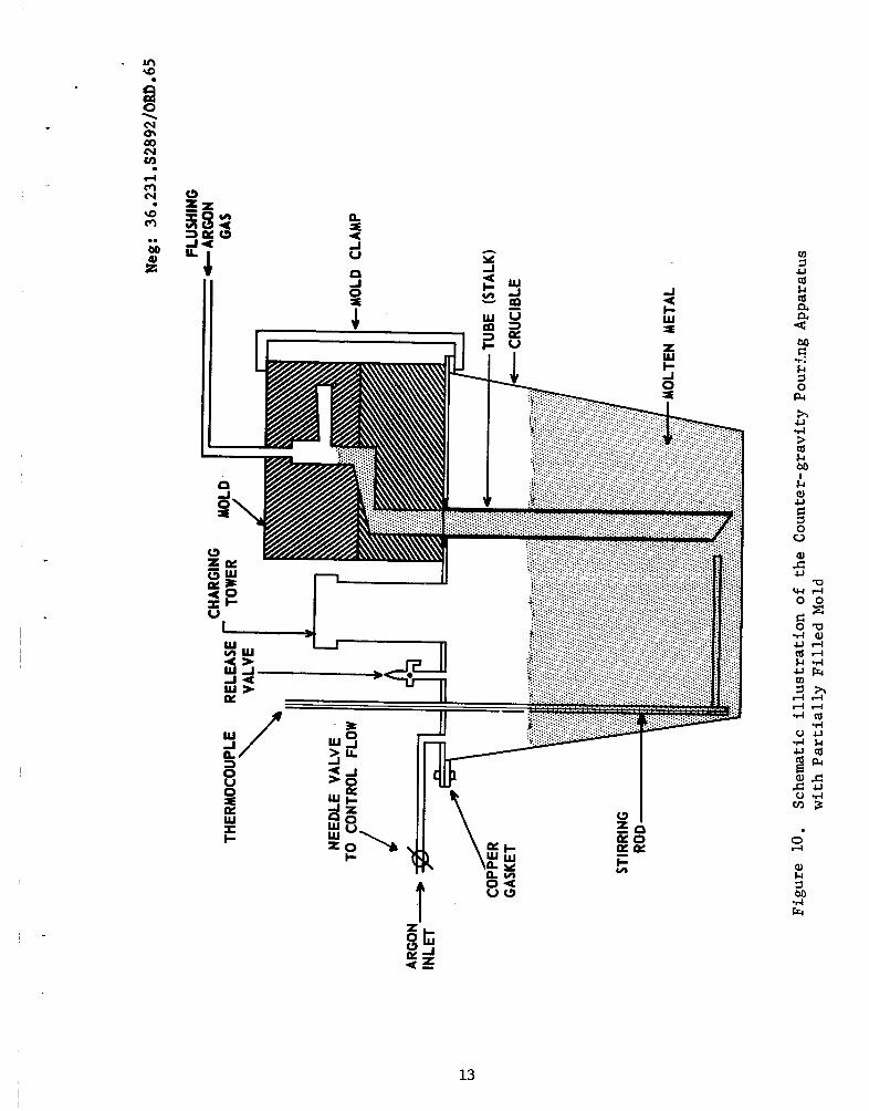
Schematic i l l u s t r a t i o n of the Counter-gravi ty Pouring Apparatus wi th P a r t i a l l y F i l l e d Mold. . . . . . . . . . . . 13
Typica l Mic ros t ruc tu res of the Cast ing i n v e s t i g a t e d i n the As-cast Condi t ion . . . . . . . . . . . . . . . . . . . 18
V

The importance of cor_servatLt.r? of wcight i n c a s t i n g s intended f o r space app l i ca t ions has pru~er l . :y dr?.wn a t t e n t i o n t o the family of a l l o y s which are based on the magcesiun- 1 Fthium system.l* U n t i l r e - c e n t l y , t hese meterials were a v a i l a b i e o ~ l y i n the wrought form and, consequent ly , design p o s s i b i l i t i e s were l imi t ed by e x i s t i n g f ab r i ca - t i o n technology. I n order t o expand the design p o s s i b i l i t i e s f o r t hese m a t e r i a l s , a s tudy was undertaken t o develop a s u i t a b l e foundry p r a c t i c e s o t h a t shaped components of g r e a t e r conpI.exity could be produced.
The problems a n t i c i p a t e d and encountered were e s soc ia t ed wi th the extremely r e a c t i v e na ture of t he a l l o y s . I n order t o minimize the pos- s i b i l i t y of mold r e a c t i o n , the f irst c a s t i n g s were poured i n t o machined s t e e l o r g raph i t e molds. L a t e r , rammed and f i r e d molds, prepared wi th a s p e c i a l g raphi te -base molding medium, were used i n an e f f o r t t o broad- en the range of shapes t h a t could be c a s t . 2
While t h i s l a t t e r p r a c t i c e was foynd t o be s u c c e s s f u l , l i m i t a t i o n s were ev ident i n t h e long f i r i n g scliedul-es r equ i r ed t o b r i n g t h e mold material t o the s t a t e where it would not r e a c t wi th the molten a l l o y . Subsequent a t t empt s , d i r e c t e d toward development of a mold m a t e r i a l and molding p r a c t i c e t h a t would more c l o s e l y approximate convent ional sand p r a c t i c e , were success fu l . It could be handled very much l i k e green sand, reqi i i red m l y low temper- a t u r e bakFrLg, and d id not r e a c t wi th t h e molten a l l o y .
This m u l d ma",rial w a s a l s o of g raph i t e base .
I n a d d i t i o n t o t'.e mold m a t e r i a l developnent, t h i s p r i o r work in - cluded some a l l o y development which w a s d i r e c t e d toward compositions more s p e c i f i c a l l y designed as folmdry a l l o y s . The most a t t r a c t i v e of t h e s e were Mg-14 Li-0.5 S i (non.-ege haTdenLng) and Mg-14 Li -3 Ag-5 Zn- 2 S i (age hardening) . These a l l o y s were eva lua ted i n comparison wi th cornpos?-ti.ons be ing used f o r w r o a g n t m ~ , t e r i a l . end were found t o exceed the l e v e l of s t a b l e p rope r t i e s obtained wi th the e x i s t i n g a l l o y s .3 , 4 ~ 5 A s a r e s u l t of t hese developments, the Gewge C. Marshal l Space F l i g h t Center a t Hun t sv i l l e , A l a . requasted Frarz?z.ford Arsena l t o f u r t h e r de- ve lop t h e c a s t i n g process s o th;,!t prototype c.astings , r ep resen t ing t y p i c a l space-vehic le requirements, could be produced and t e s t e d .
The p r i n c i p a l gaps between the ther cu r ren t s t a t e - o f - t h e - a r t and t h e t needed t o s a t i s f y the NASA reqdi renent were: (1) c a p a b i l i t y of producing l a r g e r and more complex shapes; (2) improvements requi red i n pouring p r a c t i c e t o minimlze the p o s s i b i l i t y f o r entrainment of oxide formed on t h e su r face of t he molten metal stream; and (3) t he exper- i e n c e needed wi th a v a r i e t y cf shape f e c t o r s . This l a s t cons ide ra t ion r equ i r ed t h a t a s tudy of r i g g h g p r z c t i c e f o r such cas t ings be included.
"Gee REFERENCES
1 .

This involved development of ga t ing , r i s e r i n g , and c h i l l i n g p r a c t i c e s necessary t o produce h igh q u a l i t y c a s t i n g s .
Accordingly, t h r e e components, r ep resen t ing t y p i c a l space-vehicle components, were s e l e c t e d on the b a s t s of t h e i r design complexity and p a t t e r n a v a i l a b i l i t y . The experience wi th these c a s t i n g s was t o be documented on the b a s i s of mechanical p r o p e r t i e s , processing p r a c t i c e , and me ta l lu rg ica l q u a l i t y .
S ince t h i s w a s e s s e n t i a l l y a f e a s i b i l i t y type of s tudy , the only a l l o y t e s t e d was the t e r n a r y composition. the f a c t t h a t t h i s a l l o y does develop a s a t i s f a c t o r y s t r e n g t h l e v e l i n combination wi th s u b s t a n t i a l d u c t i l i t y . magnesium-lithium compositions have been developed, the t e r n a r y a l l o y presented the same cha l lenge t o foundry process ing p r a c t i c e as did the more complex compositions e
This dec i s ion was based upon
Although h ighe r s t r e n g t h
MATERIALS AND METHODS
Cast ing Alloy
The analyses of the var ious h e a t s poured a r e shown i n Table I.
TABLE I. Composition of t h e Alloys
Weight (%) Heat Nomina 1 Actua l Analysis
S i - No MS, g I S i LA - 1 B a l 14.0 0.50 85.71 13.92 0.28 2 Bal 14-0 0.50 85.93 13.68 0.27 3 B a l 14.0 0.50 85.98 13.58 0 -29 4 B a l 14.0 1 .o 86.67 12.13 0.92
6 B a l 14.0 1 .o 87.38 11.72 0.94 5 B a l 14.0 1 .o 86 -85 12.29 0 .83
P r i o r experience wi th t h i s cornposition, u s ing c a s t - t o - s i z e t e s t b a r s poured i n t o a permanent s t e e l mold, developed the fol lowing p rope r t i e s .
U1 t ima t e tens i l e s t reng t h 19,000 t o 20,000 p s i
Yield s t r e n g t h (0.2% o f f s e t ) 15,000 p s i
Elongation (2 i n . gage length) 10 percent
2

The W l t i n g s tock f o r t h i s a l loy is l i s t e d below.
Material - Form P u r i t y
Magnesium Priwwy extruded s t i c k 99.0% rain (0.006% N a max) Lithium Ingot 99.9% min (0.006% N a max) S i l i c o n Granule s 99.9% min
Mold Material and Method
Three wooden p a t t e r n s of pa r t s t y p i c a l of the components used i n space vehicles were provided by the GeorgeC. Marshall Space F l i g h t Center. These were:
(a) Alignment bracket , pa r t No. GM470051 (Figure 1);
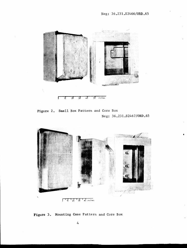
(b). Small box, no p a r t number, with core box (Figure 2);
(c) Mounting case, p a r t No. Gc503517, with core box (Figure 3) . Neg : 36 -23 1 .S2465/ORD . 65
8
I ' 11 21 ' 31 ' 4 1 inches
Figure 1. Alignment Bracket P a t t e r n
3
Neg : 3 6 .23 1 . S 24 6 6 /Om. 65
Figure 2. Small Box P a t t e r n and Core Box Neg: 3 6.23 1 .S2467/ORD. 65
/
I ' 1 1 ' 2 1 ' 31 ' 4 1 inches
Figure 3 . Mounting Case P a t t e r n and Core Box
4

The f i r s t c a s t i n g s were made us ing an i n h i b i t e d molding sand which was similar t o t h a t used f o r s tandard magnesium c a s t i n g a l l o y s . The c a s t i n g s which were poured i n t o t h e s e molds showed evidence of severe metal-mold r e a c t i o n . An i n h i b i t e d z i r con mold a l s o r eac t ed wi th the molten metal.
Promising r e s u l t s were f i n a l l y obta ined wi th a g raph i t e mold material which had been developed concurren t ly on another program. This m a t e r i a l was modified s o as t o meet the requirements f o r t h e magnesium-lithium cas t ings . The f i n a l composition was a mixture of e l e c t r i c furnace g raph i t e powder (Nat iona l Carbon Company No. CPBB4P5, grade 99,9% pure) , water, and ben ton i t e . The s i e v e a n a l y s i s of the m a t e r i a l i s given i n Table 11. The AFS g r a i n f ineness number f o r t he g raph i t e p a r t i c l e s was approximately 4 7 .
TABLE 11, Sieve Analysis of Graphi te Molding Materiala (100-gram sample; shaker t i m e , 15 minutes)
U . S . Std Weight Sieve Opening Sieve No. Grams Cumulative % Mesh (microns)
30 40 60 80
100 140 200 2 70 P an
- 4 .O
7 1 ,O 18 .O
2.8 1.3 0.6 0.3 0 . 4
4 .O 75 .O 93 .o 95.8 97,l 97.7 98 .O 98.4
28 35 60 80
100 150 200 2 70
5 90 420 250 177 149 10 5
74 53
aEquivalent t o AFS g r a i n f ineness No. 47
A b r i e f i n v e s t i g a t i o n was made t o determine t h e green compres- s i v e s t r e n g t h and permeabi l i ty of the mold m a t e r i a l wi th d i f f e r e n t water conten ts . From these l imi ted da ta i t w a s determined t h a t t h e mold m a t e r i a l had a n AFS permeabi l i ty va lue of 150 and a compressive s t r e n g t h of 3 p s i . O p t i m u m composition corresponded t o the fol lowing.
Mater ia 1 Weight %
60 mesh g raph i t e Western ben ton i t e Tap water
90 .o 5 .o 5 .O
Mixing procedure cons i s t ed of mulling the dry ing red ien t s f o r f i v e minutes , adding water, and mulling f o r an a d d i t i o n a l f i v e minutes.
5

This material behaved l i k e ordinary foundry sand when i t w a s hand rammed around the p a t t e r n . The molds were baked a t 250" F f o r 24 hours t o remove moisture. Cores were of the same composition and were baked i n the same way as t$e molds.
Because a new technique of pouring (described la ter i n the s e c t i o n "Melting and Casting")was employed t o make the c a s t i n g s , a new system of g a t i n g and r i s e r i n g had t o be developed. The ga t ing system was de- s igned t o minimize turbulence i n the molten metal by a slow uniform flow of molten metal from the bottom t o the top of the cas t ing . This g a t i n g system cons is ted , e s s e n t i a l l y , of a r e l a t i v e l y l a rge sprue, a sprue bas in t o ca t ch the f i r s t metal i n t o the c a s t i n g , and a fan-shaped runner which fed i n t o a r ing ga te around the cas t ing . To prevent gas entrapment i u the mold, extensive ven t ing was used on the top of the mold. A d e s c r i p t i o n of the ga t ing and r i s e r i n g of each c a s t i n g follows.
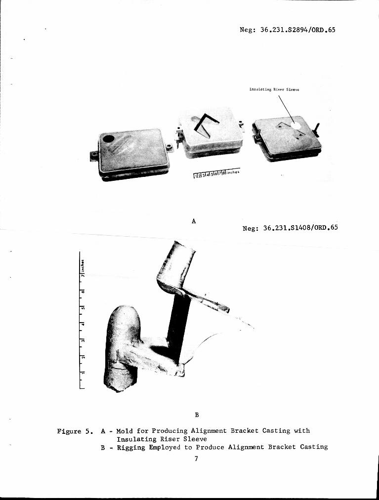
Alignment Bracket (Figure 4) . This b racke t had approximate dimensions of 7 by 4 by 4 in . , and weighed 1-1/4 lb . ness var ied from 1 / 2 t o 1 / 4 inch. Figure 5 (A and B) shows the r igg ing employed. tended p a s t t he c a s t i n g t o form a sprue bas in . This ex tens ion provided both a "cushion" t o take the i n i t i a l impact of the molten metal and a b a s i n t o hold the f i r s t metal i n t o the c a s t i n g . From the pouring ga te , a tabered fan-shaped runner led i n t o a ga te which w a s a t t ached t o the en t i re bottom of the c a s t i n g .
The w a l l t h i c k -
It should be noted i n Figure 5B t h a t the pouring g a t e ex-
Neg: 36.231.S1406/0RD.65
4
Figure 4 . T e s t B a r Loca t ions i n Alignment Bracket Cast ing
6
Neg: 36.231.S2894/ORD.65
Insulating Riser Sleeve
A Neg : 3 6 . 23 1 .S 1408/ORD. 65
' I
L.
B
Figure 5 . A - Mold for Producing Alignment Bracket Casting with
B - Rigging Employed t o Produce Alignment Bracket Casting Insulating Riser Sleeve
7

The major problem with t h i s p a r t w a s t h e entrapment of gas and t h e occurrence of shrinkage a t the top of t he c a s t i n g . By c a r e f u l l y vent ing the t o p and using a n i n s u l a t e d b l i n d r i s e r , t he problem was cor- r ec t ed . The i n s u l a t e d riser s l eeve was prepared wi th a gypsum-bonded investment material, using b o r i c a c i d (1 percent of investment by weight) as, the i n h i b i t o r . Eight t e s t b a r s w e r e cu t from one cas t ing . These loca t ions are shown i n Figure 4.
Small Box (Figure 6) This i t em had approximate dimensions of 8 by 7 by 3 in . and weighed 2 lb . The w a l l th ickness v a r i e d from 1/8 t o 3 / 4 inch. Figure 7 (A, B , and C) shows the r igg ing employed.
This c a s t i n g presented a problem i n feeding because t h r e e of t he s i d e w a l l s were 1/8 inch t h i c k , while t h e f o u r t h w a s 1 / 2 inch th i ck . On the t h r e e t h i n s i d e s , t he re w a s a l s o a 1 / 2 inch f l ange t o which the r i n g ga te w a s a t t ached .
To i n s u r e proper s o l i d i f i c a t i o n i n t h i s c a s t i n g , i n s u l a t e d b l i n d risers and c h i l l s had t o be u t i l i z e d . Two heavy i n s u l a t e d b l i n d risers were used t o feed the t h i c k s i d e of t he cas t ing . Opposite t h e entrance of t h e s e g a t e s , g raph i t e c h i l l s were used.
Neg : 36.23 1 .S1404/ORD. 65
Figure 6. Test Bar Locat ions i n Box type Cas t ing
8

Graphite Chill Core
3\ 41 5\61 7\81 inches
A Neg: 36.231.S1475/0RD.65
Neg: 36.231.S2896/ORD065
Insulating Riser S leeve
Neg : 36 . 23 1 .S 1476/0RD. 65
C
F igu re 7. A - Mold f o r Producing Box type Cas t ing with Core, C h i l l s ,
B - Cope view of Box type Cast ing showing t h e Rigging employed C - Drag view of Box type Cast ing showing Gating and Riser ing
and I n s u l a t i n g Sleeves
employed
9

A mounting pad on the i n s i d e of t he c a s t i n g was s u b j e c t t o bo th i n t e r n a l and e x t e r n a l shrinkage. This problem w a s a l l e v i a t e d by means of a graphi te c h i l l shaped t o the same a r e a as the pad. Alone, t h i s c h i l l w a s not f u l l y success fu l ; t h e r e f o r e , the o u t e r s u r f a c e of t he cast- i n g i n t h i s a r e a was thickened, a s shown i n Figure 7B. Both of t hese measures completely el iminated t h i s problem. The top s u r f a c e of the mold w a s generously vented t o prevent t h e entrapment of gas on the upper su r - f aces . Ten test b a r s were c u t from the c a s t i n g . Their l o c a t i o n s are shown i n Figure 6.
-
Mounting Case (Figure 8). This case had approximate dimen- s i o n s of 10 by 7 by 6 inches , and weighed 2-1/2 pounds. The w a l l t h i ck - ness var ied from 1/8 t o 1 inch. Figure 9 ( A , B y and C) shows the r i g - ging employed. A sprue b a s i n and fan-shaped runner, s imi l a r t o those i n the o t h e r c a s t i n g s , were employed f o r t h i s p a r t . A r i n g ga te w a s used which went around the e n t i r e circumference of the cas t ing . This c a s t i n g w a s complicated by the presence of t h ree " f i n g e r s ," roughly t h r e e inches long by 1 / 2 inch diameter, p ro j ec t ing down from the top su r face of t he c a s t i n g (Figure 9B). To insu re proper s o l i d i f i c a t i o n , g raph i t e s l e e v e s , machined t o t he same contour a s the " f inge r s , " were i n s e r t e d i n t o t h e core. The machined g raph i t e acted as a c h i l l , and good d i r e c t i o n a l s o l i d - i f i c a t i o n was obtained i n t h e p ro jec t ions .
Neg : 3 6.23 1 .S1405 /ORD . 65
Figure 8. Test Bar Locations i n Mounting Case Cast ing
10

1 ~ ~~ ~~
I I
Neg: 36.231.S2895/0RDO65
Graphite Chill
Stc,r 1 Chill I
Neg: 36.231.S1477/ORD -65
Figure 9. A - B -
c -
A
Neg : 3 6 -23 1 .S 1478 /ORD . 65
C
Mold f o r producing Mounting Case Casting with Core, C h i l l s , and I n s u l a t i n g Riser Sleeves Drag view of Mounting Case Casting showing Gating and R i se r ing employed Cope view of Mounting Case Casting showing the Rigging employed
11
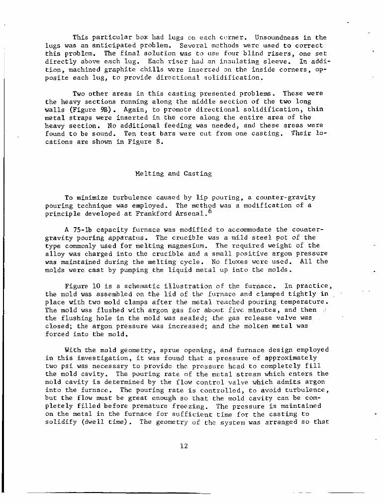
This p a r t i c u l a r box had lugs on. each ccxner. Unsoundness i n the lugs w a s an a n t i c i p a t e d problem. t h i s problem. The f i n a l s o l u t i o n w a s t o use four b l i n d risers, one s e t d i r e c t l y above each lug. t i o n , machined g raph i t e c h i l l s were i n s e r t e d an the i n s i d e co rne r s , op- p o s i t e each lug , t o provide d i r e c t i o n a l . s o l i d i f i c a t i o n .
Seve ra l methods were used t o c o r r e c t
Each r iser hrid an i n s u l a t i n g s leeve . I n addi-
Two o the r a r e a s i n t h i s c a s t i n g presented problems. These were the heavy sec t ions running along t h e middle s e c t i o n of the two long wal ls (Figure 9B). Again, t o promote d i r e c t i o n a l s o l i d i f i c a t i o n , t h i n meta l straps were i n s e r t e d i n the core along the e n t i r e area of t h e heavy sec t ion . No a d d i t i o n a l feeding was needed, and these areas were found t o be sound. Ten t e s t ba r s were c u t from one c a s t i n g . Thei r lo- c a t i o n s a re shown i n Figure 8.
Melt ing and Cas t ing
To minimize turbulence caused by l i p pouring , a coun te r -g rav i ty pouring technique was employed. p r i n c i p l e developed a t Frankford Arsenal a 6
The method w a s a modi f ica t ion of a
A 75-lb capac i ty furnace was modified t o accommodate the counter- g r a v i t y pouring apparatus . type commonly used f o r mel t ing magnesium. a l l o y w a s charged i n t o the c r u c i b l e and a s m a l l p o s i t i v e argon pressure was maintained during the mel t ing cyc le . No f luxes were used. A l l t h e molds were c a s t by pumping the l i q u i d metal up i n t o the molds.
The c r u c i b l e was a m i l d s t e e l pot of the The r equ i r ed weight of t h e
Figure 10 i s a schematic i l l u s t r a t i o n of the furnace. I n p r a c t i c e , the mold was assembled on the l i d of the furnace and clamped t i g h t l y i n p lace with two mold clamps a f t e r the metal reached pouring temperature . The mold was f lushed wi th argon gas f a r about f i v e minutes , and then the f lush ing hole i n the mold was s e a l e d ; the gas r e l e a s e va lve was c losed; the argon pressure was inc reased ; and the molten metal w a s forced i n t o the mold.
With the mold geometry, sprue opening, and furnace des ign employed i n t h i s i n v e s t i g a t i o n , i t w a s found t h a t a p re s su re of approximately two p s i was necessary t o provide the p re s su re head t o completely f i l l the mold cavi ty . The pouring r a t e of t h e meta l stream which e n t e r s t he mold cavi ty i s determined by the flow c o n t r o l va lve which a d m i t s argon i n t o the furnace. The pouring ra te i s c o n t r o l l e d , t o avoid tu rbu lence , b u t the flow m u s t be g r e a t enough so t h a t t h e mold c a v i t y can be com- p l e t e l y f i l l e d be fo re premature f r eez ing . The p res su re i s maintained on t h e metal i n the furnace f o r s u f f i c i e n t time f o r t h e c a s t i n g t o s o l i d i f y (dwell t i m e ) . The geometry of the system w a s arranged s o t h a t
1 2
o a V U t
m 7 U (d
a 3 4
h U .rl 3 m & M I & 0 U c: 7 0 u
13

t h e meta l i n the s t a l k and i n the sprue c a v i t y of t h e mold would be the l a s t t o f r eeze . The pressure r e l e w e va lve i s opened while the meta l i n these reg ions i s s t i l l l2qui.d and, t he r? fo re , t he meta l can d r a i n back i n t o the furn-ace. from t h e furnace l i d .
T h i s permits easy sepa ra t ion of the mold
The drained sprue c a v i t y may be dbser-ved i n Figure 9B. The dwell t i m e i s empir ica l ly determined f o r each c a s t i n g conf igura t ion . For these c a s t i n g s , a pressure of two p s i , he ld f o r approximately two min- u t e s , w a s found t o be s a t i s f a c t o r y f o r f i l l i n g the mo1.d and i n s u r i n g mold-furnace sepa ra t ion .
To minimize turbulence , i t w a s d e s i r a b l e t o use t h e lowest pouring r a t e necessary t o avoid misruns. The time of pour corresponding t o t h i s r a t e was found t o be approximately s i x seconds, a t a pouring tem- pe ra tu re of 1350" F.
One of t he major advantages of th.e c a s t i n g technique was the f a c t
The argon s h i e l d which p ro tec t ed the molten metal t h a t no f luxes were used. A s a r e s u l t , t he re was nc' f l u x entrapment i n the f i n a l ca s t ings . a l s o served t o fo rce the metal i n t o the mold.
Tes t Procedure
Mechanical p r o p e r t i e s were determined on machined s tandard 0.252 inch diameter t e n s i l e specimens taken from t y p i c a l c a s t i n g s and comc pared wi th s e p a r a t e l y c a s t 0.505 inch diameter t e n s i l e specimens taken from the same hea t of metal. The t e n s i l e specimens were t e s t e d a t room temperature, us ing a crosshead speed of 0.0s inch/minute , s t r e n g t h , 0.2 percent o f f s e t y i e l d s t r e n g t h , and percent e longat ion were measured.
T e n s i l e
Representat ive specimens were removed from t h e c a s t i n g s and ex- amined meta l lographica l ly . A l l the css t i r igs were radiographed com- p l e t e l y . Where de fec t s were noted on the f i l m , s e c t i o n s were removed from t h e cas t ings and f r a c t u r e d through the d e f e c t s . An examination w a s then made of the f r a c t u r e d su r face t o determine the cause of t h e d e f e c t ; i . e . , g a s , ox ide , o r shr inkage .
14

Molding and RiggLng
The 60 -me s h graph i t e p owd e r - 5 €1 e Y c :ii ;:it :$e s t e r n be n t on i t e - wa t e r mixture was used, without i r i h ib i to r s , t o form a mold i n t o which the magnesium-lithium a l l o y could be cas t s7.iccessfully. The molding char- a c t e r i s t i c s of the g raph i t e ma te r i a l w e r e similar t o "green" sand. The g a t i n g system developed dur ing t h i s i n v e s t i g e t i o n w a s d i f f e r e n t from t h a t used i n the g r a v i t y pouring of magnesium i n t o sand molds. This d i f f e r e n c e w a s no t unexpected, cons ider ing the d i f f e r e n c e i n pouring and the wide d i s p a r i t y i n hilt conduc t iv i ty between the two types of mold. The r a t i o of the c ros s - sec t ion area of the sprue t o t h a t of the fan-shaped runner t o tha t o f t!w i n g a t e was approximately 1 : 1-1 /2 : 2 . This r a t i o was a r r ived a t em.piri.cally, b u t i t did provide a reasonably nonturbulent flow of .n?etal i n t o the mold cav i ty .
Meting and Casti.r?g
A f t e r development of proper pressure , f low r a t e , and hold ing t ime, l i t t l e d i f f i c u l t y w a s encountered I n t he product ion of c a s t i n g s by means of t h e counter -gravi ty pouring technique, The c z s t i n g s broke out c lean- l y from the mold, and the re were no s.i-gns of mold-metal r e a c t i o n .
Chemical ana lyses of the f i r s t h e a t s of the meta l shoved t h a t the s i l i c o n l e v e l was 0.29 percent S i , r a t h e r than 0.5 percent . Therefore , on subsequent h e a t s , a d d i t i o n a l s i l i c o n was added t o compensate f o r the l o s s e s . On the second h e a t s , however, t he s i l i c o n conten t was 0.94 p e r - c e n t . P a s t experience has shown th2: throiigh a s u f f i c i e n t number of h e a t s , the chemistry can be carefu1i.y cor:i.:rol'l_ed. Therefore , s i n c e the chemistry did not a f f e c t the foundry eharact:eri.stics , no f u r t h e r time was spen t on this phase of the pr~gra.m.. k!.so, i t : has been shown t h a t 0.5 percent S i and 0.9 percezzt S i n;agnes~.i;ru-lFtheum a l l o y s have ap- proximately the same u l t ima te and y i e ld strerigth.s, a l though i n the l a t - t e r , t h e e longa t ion i s r e d ~ c e d . ~
Test Prcper t2es
The r e s u l t s of the mechanical t es t s are shmwn i n 'Tables 111, I V Y and V . There w a s l i t t l e v a r i a t i o n i n the u l t ima te s t r e n g t h , y i e l d s t r e n g t h , o r percent e longat ion from c a s t i n g t o c a s t i n g . Within the same c a s t i n g , where the t e s t b a r s were t-akzn from a reas of d i f f e r e n t c r o s s s e c t i o n , t he mechanical p rope r t i e s were s i m i l a r . This s i m i l a r i t y
15

was probably due t o the f a c t t h a t the g raph i t e mold m a t e r i a l had such a h igh heat conduct iv i ty t h a t t he molten metal f roze quickly i n a l l the t e s t e d sect!-on s i z e s I
TABLE 111, The Mechanical P r o p e r t i e s of T e s t Bars Cut from t h e P.lignrr.e;lt BrLicket
Test S t r eng th ( p s i ) Elongat ion Bar Yie ld __ Ultimate T e n s i l e (%) No .a 0.28 S i 0.92 S i 0.28 S i 0 .92 S i 0.28 S i 0.92 S i -- -I__ -
9,100 12,800 b 13,200
9,300 13,200 b 12,900
9,900 12,600 b 12,700
9,900 13,000 b 13,000
14,500 18,300 14,400 18,700 12,200 18,700 14,400 18,300 14,100 17,300 14,200 18,400 15,200 18,000 15,600 19,300
16 .O 6.4 C 5.5 C 7.2
15 "0 5.2 9 -0 5.5
10 .o 6.5 15 .O 6.5 23 .O 6.5
d 9,800 12,900 15,100 18,500 14 .O 7 .O
aTest ba r l o c a t i o n s as shown i n Figure 4 . . bYield s t r e n g t h no t obtained. CBroke outs ide gage marks. dSeparately c a s t test b a r s .
TABLE I V . The Mechanical P r o p e r t i e s of T e s t Bars Cut from t h e Box type Css t ing
Tes t Bar No .a
1 2 3 4 5 6 7 8 9
10
-
C
S t r e n g t h ( p s i ) E 1 onga t i on - - Y i e l d Ult imate Tens i l e (%) -
0.27 S i 0 ,83 S i 0 ,27 S& 0 , 8 3 S i 0.27 S i 0.83 S i
9,400 13,300 b 13 200
9,200 13,200 b 12,900
9,300 12,800 b 13,000
9,200 13,200 b 13,400
9,400 13,000 b 13,200
14,800 18,800 15,400 18,300 14,900 18,500 14,900 18,400 15,200 18,200 15,100 18,700 14 , 700 18,300 14,700 18,500 14,800 18,800 15,400 18,500
22 .o 26 .O 26 .O 26 .O 29 .O 26 .O 27 .O 12 .o 27 .O 25 .O
5 "5 6 .O 7 ,O 6.5 6.5 6.5 7 .O 5.5 6 -0 6 -0
9,500 13,200 15,100 18,300 20 .o 6.5
aTest bar l oca t ions a s shown i n F igure 6 . b y i e l d s t r e n g t h not ob ta ined . CSeparately c a s t t e s t b a r s .
16
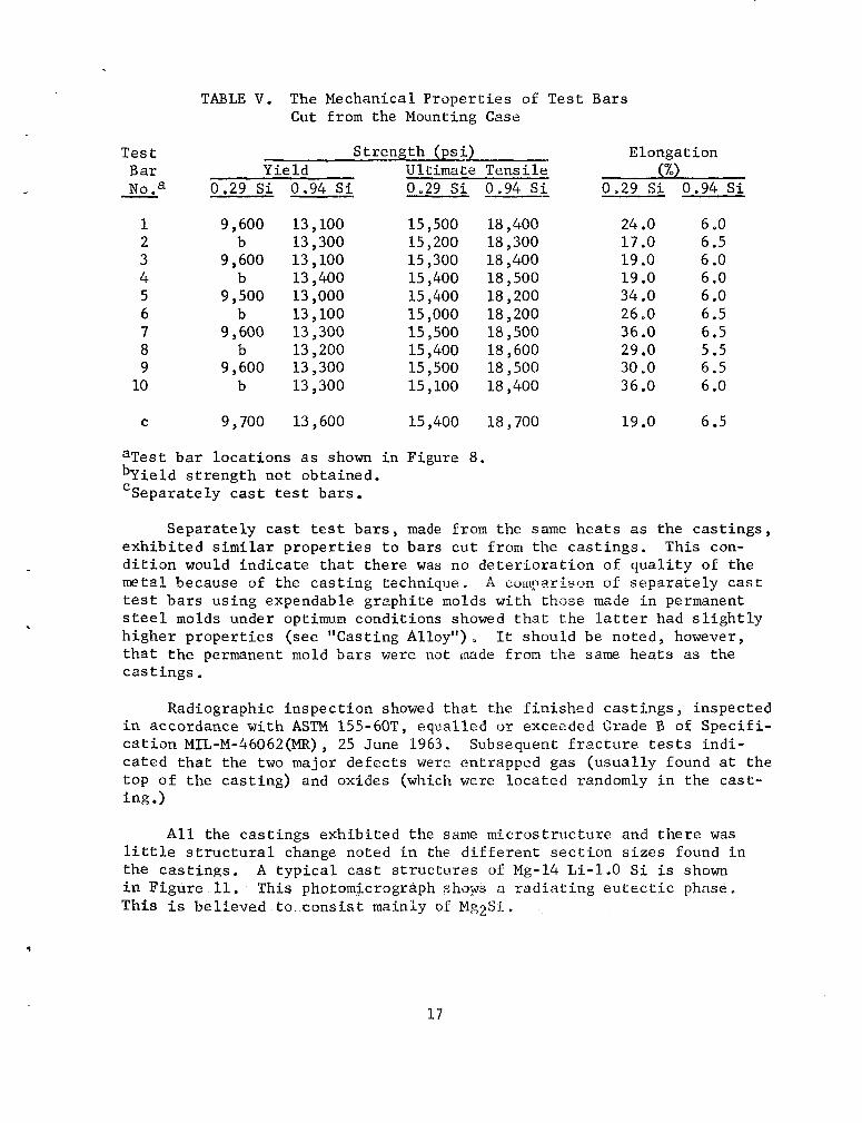
TABLE V. The Mechanical P rope r t i e s of Tes t Bars Cut from the Mounting Case
c
Tes t Bar No .a
1 2 3 4 5 6 7 8 9 10
-
C
St reng th ( p s i ) Elongat ion Yie ld U l t i m a t i ? Tens i l e (%)
0.29 S i 0.94 S i 0.29 S i 0.94 S i 0.29 Si 0.94 S i
9,600 13,100 b 13,300
9,600 13,100 b 13,400
9,500 13,000 b 13 , 100
9,600 13,300 b 13 , 200
9,600 13,300 b 13,300
15,500 18,400 15 , 200 18 , 300 15,300 18,400 15,400 18,500 15,400 18,200 15,000 18,200 15,500 18 , 500 15,400 18 , 600 15,500 18,500 15,100 18,400
24 .O 6 .O 17.0 6.5 19 .o 6 .O 19 .o 6 .O 34 .O 6 .O 26 .O 6.5 36 .O 6.5 29 .O 5.5 30 .O 6.5 36 .O 6 .O
9,700 13,600 15,400 18,700 19 .o 6.5
aTest b a r l oca t ions a s shown i n Figure 8.
'Separately c a s t t es t b a r s i e Id s t r e n g t h not obtained .
Separa t e ly cast t e s t b a r s , made from the same h e a t s as the c a s t i n g s , e x h i b i t e d similar p r o p e r t i e s t o ba r s c u t from the c a s t i n g s . This con- d i t i o n would i n d i c a t e t h a t t h e r e was no d e t e r i o r a t i o n of q u a l i t y of t h e metal becatlse of the c a s t i n g teehiiique. A C n r I t p a T i s m of s e p a r a t e l y c a s t t es t bars us ing expendable g raph i t e molds wi th those made i n permanent s t e e l molds under optimum condi t ions showed t h a t t h e l a t t e r had s l i g h t l y h ighe r p r o p e r t i e s (see "Casting Alloy") It should be noted, however, t h a t t h e permanent mold 3ars were not made from the same hea t s as the c a s t i n g s .
Radiographic in spec t ion showed t h a t the f i n i s h e d c a s t i n g s , inspected i n accordance w i t h ASTM 155-60TY equal led u r exceeded Grade B of S p e c i f i - c a t i o n MIL-M-46062(MR) , 25 June 1963. Subsequent f r a c t u r e t e s t s i n d i - ca t ed t h a t the two major de fec t s were entrapped gas (usua l ly found a t t h e top of t he cas t ing ) and oxides (which were loca ted randomly i n the c a s t - i n g .)
A l l the c a s t i n g s exh ib i t ed the same mic ros t ruc tu re and t h e r e was l i t t l e s t r u c t u r a l change noted i n the d i f f e r e n t s e c t i o n s i z e s found i n the c a s t i n g s . A t y p i c a l c a s t s t r u c t u r e s of Mg-14 Li-1.0 S i i s shown i n F igure 11. This photomicrogrkph shops a r a d i a t i n g e u t e c t i c phase. Th i s i s be l i eved t o c o n s i s t mainky uf Mg2Si.
1 7

Neg: 36.231 .S2893/0RD.65
I ' i:
Nital etch lOOX
- I\\ 'I r \ \
11'
500X Nital etch
Figure 11, Typical Microstructures of the Casting investigated in the As-cast Condition
18

CONCI,US IONS
1. Shaped c a s t i n g s of magnesium- l i t h ium components (with des ign f e a t u r e s a n t i c i p a t e d i n space vehic les ) car? be produced i n an expendable noninhib i ted mold made of g raph i t e p a r t i c l e s bonded wi th ben ton i t e and water.
2. Cast ings can be produced r e l a t i v e l y f r e e of i n c l u s i o n s and entrapped gas bubbles by means of the counter -gravi ty technique of pouring.
3 , A high and uniform l e v e l of mechanical p r o p e r t i e s w a s obtained i n t es t b a r s c u t from c a s t i n g s . These sound c a s t i n g s were produced by us ing convent ional r i s e r i n g and c h i l l i n g p r a c t i c e s i n combination wi th t h e counter -gravi ty pouring technique.
1 9

REFERENCES
1. T . G. Bryer , A. M. Sabrof f , and P , D, F r o s t , "Development of Magnesium-Lithium Alloys f o r S t r u c t u r a l Appl ica t ions , ' I B a t t e l l e M e m o r i a l I n s t i t u t e (Contract NAS8-5265), f o r George C. Marsha l l Space F l i g h t Center , NASA, May 1964.
2 . A. S a i a and R. E. Edelman, "Producing Magnesium-Lithium Alloy Castings," Foundry, 19 August 1962.
3 . A. Saia and R. E . Edelman, " S i l i c o n and Zinc E f f e c t s on Magnesium- Lithium and Magnesium-Lithium-Silver Alloys," Trans AFS, 72 , 1964.
4. A. S a i a and R . E. Edelman, "The S t r e s s Corrosion and Elevated Temperature P r o p e r t i e s of Magnes ium-Li thium- S i l i c o n A 1 l oys ,I' Trans Magnesium ASSOC, 5 October 1964,
5. R. S. Busk, D. L. Leman, and J. J . Casey, "The P r o p e r t i e s of Some Magnes ium-Lithium Alloys Containing Aluminum and Zinc , I 1 AIME Trans, 188, 1950.
6. S . Lips on. and F . Ripkin, "Pressure Cas t ing i n Investment Molds , I 1
Trans AFS, 73 , 1965.
20

I . OqlClNATlN G ACTIVITY (Corporate author) FRANKFORD ARSENAL, Phi l ade lph ia , Pa.
(Attn: SMUFA L3100)
2 a R E P O R T S E C U R I T Y C L A S S I F I C A T I O N
Unclas s i f i ed
NA 2 b G R O U P
C .
i. REPORT DATE
N o v d 1965 1.. C O N T R A C T OR G R A N T NO.
NASA Defense Purchase Request H-7150El b. P R O J E C T NO.
9b . O T H E R R E P O R T NO@) ( A n y othernumbers that may be assigned this report)
7 a . T O T A L NO. O F P A G E S 76. NO O F R E F S
23 S i x
R-1785 sa . O R I G I N A T O R ’ S R E P O R T N U M B E R ( S )
d. I IO. A V A IL ABILITY/LIMITATION NOTICES
D i s t r i b u t i o n of t h i s r e p o r t is unl imited.
i Z SPOEcSORihG M i i l T A R r A C T I V I T Y ! ! SUPPLEMENTARY NOTES
NASA Geo. C. Marsha l l Space F l i g h t Cente.
13 ABSTRACT
A process has been developed f o r success fu l ly c a s t i n g a number o r prototype aerospace components us ing the t e rna ry magnesium-lithium-sil icon a l l o y . components contained many of the d e s i g n elements a n t i c i p a t e d i n aerospace hardware of this type.
It w a s found t h a t convent ional magnesium sand foundry p r a c t i c e w a s no t satis- f a c t o r y . A new molding m a t e r i a l , based upon bentonite-bonded graphi te powder, was employed. Melt ing and pouring p r a c t i c e w a s a l s o modified t o cope wi th the r e a c t i v na tu re of t h e a l l o y
b a r s s e c t i o n from the c a s t i n g s were evaluated and found t o be s a t i s f a c t o r y and t o correspond wi th e a r l i e r experience on sepa ra t e ly c a s t t e s t b a r s .
These
The rad iographic q u a l i t y of the cas t ings and mechanical p rope r t i e s of t e s t
D D YNR1. 1473 UNCLASSIFIED - -
L c u r i t y Classification

~. UNCLASSIFIED Securitv Classification
- 14.
-~ ~.
K E Y WORDS
Magnesium Magnes ium-Li thium Lightweight Alloys Casting Expendable Mold Material Aerospace Components
INSTWCTION
1. ORIGINATING ACTIVITY Enter the name and-address of t he contractor, subcontractor, grantee, Department of D e fense activity or other organization (corporate author) issuing the report. 2a. REPORT SECURiTY CLASSIFICATION Enter the over- all security classification of the report. Indicate whether “Restricted Data’’ is included Marking is to be in accord- ance with appropriate security regulations. 2b. GROUP: Automatic downgrading is specified in DoD Di- rect ive 5200.10 and Armed Forces Industrial Manual. Enter the group number. Also, when applicable, show that optional markings have been used for Group 3 and Group 4 as author- ized.
3. REPORT TITLE: Enter the complete report t i t le i n all capital letters. Titles in all c a s e s should be unclassified. If a meenittgfd t f t k cannot be- seJTcted wjt$out classifice ti&n, &ow t i t le classification in all capi ta ls i n parenthesis immediately following the title. 4. DESCRIPTIVE NOTES If appropriate, enter the type of report, e.g., interim, progress, summary, annual, or final. Give tJw inclusive Antes when a sDecific reporting period is coveiedr
5. AUTHOR(S): Enter the namels) of author(s1 as sLown on 0 ) II the report. Butet Iast-name, first riame, Addle initial. If military, show rank and branch of service. the principal author is an absolute minimum reauirement. 6. REPORT DATE: Enter the date of the report a s day, rhonth, ye& or month, yeat. If more than one date appears on i h e rqpport, use da te of publication. 7a. TOTAL NUMBER OF PAGES The total page count should follow normal pagination procedures, i. e., enter the number of pages contafnlng infotmation 76. NUMBER O F REFERENCES Enter the total number of references cited in the report. 8a. CONTRACT OR GRANT NUMBER: If appropriate, enter the applicable number of the contract or grant under which the report was writ ten 8b, 8c. &, 8d. PROJECT NUMBER Enter the appropriate military department identification, such a s project number, subproject number, system numbers, task number, etc. 9a. ORIGINATOR’S REPORT NUMBER(S): Enter the offi- cial report number by which the document will be identified and controlled by the originating activity. T h i s number must b e unique to this report. 96. OTHER REPORT NUMBER(S): If t he report has been assigned any other report numbers (erther by the origlnator 3r by the sponsor), a lso enter t h i s number(s).
i‘he name of
L I N K A
R O L E W T
L I N K B
R O L E W T
L I N K C
.O. AVAILABILITY/LIMITATION’ NOTICES Enter a6y i‘im itations on further dissemination of the report, other than thos’ imposed by security classification, using standard statements such as:
(1)
(2)
( 3 )
“Qualified requesters may obtain copies of th i s report from DDC’’ “Foreign announcement and dissemination of t h i s report by DDC is not authorized.’’ “U. S. Government agencies may obtain copies of t h i s report direcdy f rom DDC. Other qualified .bDC users shal l request through
’I
(4) “U. S. military agencies may obtain copies of t h i s report directly from DDC Other qualified use r s shal l request through
$ 1
(5) “All distribution of this report is controlled Qual- ified DDC users shall request through
I *
fi rbe-rwort has bee0 furnished to the Office o f Technica Servicqs, Department of Commerce for sale to the public, ind catetiiiis fac’t and enter the price, if known. 11. SUPPLEMENTARY NOTES Use for additional. explana- tory notes 12. SPONSORING MItITA,RY ACTIVITY: Enter- the name. Of the dFartmenta1 project office or laboratory sponsoring, ( p a y in&for) t h e rese’s’rch and deJelopment. 13. ABSTRACT: Enter an abstract 1giGing.a. brief . a n d ; f w f b l ; s4mmar.y of the document .indicative of the report, ,even thougl it ,may a l so appear elsewhere in the body-of the, technical re- pwt: If additidnal s p a c e required, a Continuation Sheet shall b e attached
ports be unclassified. Each paragraph of the abstract shal l end with an indication of the military security classification of the information in the paragraph, represented a s (TS), (s),
Include*addr&3B’
It is highly desirable that the abstract of c lass i f ied re-
(C), or (V) .
ever, the suggested length i s from 150 to 225 words. 14. KEY WORDS: Key words are technically meaningful tern or short phrases that characterize a report and may be- used f index entries for cataloging the report. se lected SO that no security c lassi f icat ion is required. Iden f ie rs . such a s equipment model designation, trade name, mili tary project code name, geographic location, may be used a s key words but will b e followed by an indication of technical context. optional.
There i s no limitation on the length of t he abstract . How
Key words must be
T h e assignment of l inks, rules, and weights IS
UNCLASS I F IED Security Classification
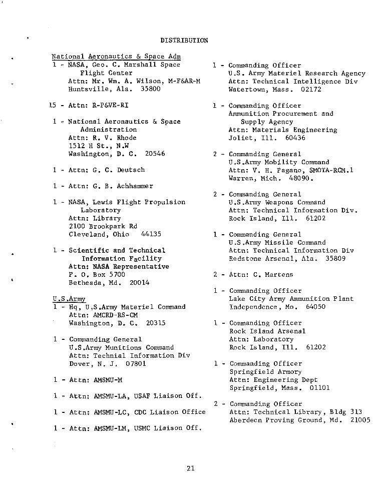
DISTRIBUTION
Na t iona l Aeronautics & Space Adm 1 - NASA, Geo. C. Marsha l l Space 1 - Commanding O f f i c e r
F l i g h t Center U .S . Army M a t e r i e l Research Agency Attn: M r . Wm. A. Wilson, M-FUR-M Attn: Technica l I n t e l l i g e n c e Div Hun t sv i l l e , Ala. 35800 Watertown, Mass. 02172
.
15 - Attn: R-P&VE-RI
1 - Nat iona l Aeronautics & Space Adminis t ra t ion
Attn: R. V. Rhode 1512 H S t . , N.W Washington, D. C. 20546
1 - Attn: G. C. Deutsch
1 - Attn : G, B. Achhammer
1 - NASA, Lewis F l i g h t Propuls ion Lab o r a t o r y
At tn : L ibrary 2100 Brookpark Rd Cleveland, Ohio 44135
1 - S c i e n t i f i c and Technica l Information F a c i l i t y
At tn : NASA Representa t ive P. 0. Box 5700 Bethesda, Md. 20014
U .S .Army 1 - Hq, U,S.Army M a t e r i e l Command
At tn : AMCRD-RS-CM Washington, D. C. 20315
1 - Commanding General U .S .Army Munitions Command At tn : Technia l Information Div Dover, N . J . 07801
1 - Attn : AMSMU-M
1 - Attn : AMSMU-LA, USAF L ia i son Off.
1 - Attn : AMSMU-LC, CDC L ia i son Off ice
1 - Attn : AMSMU-LM, USMC Lia i son Off ,
1 - Commanding O f f i c e r Ammunition Procurement and
Supply Agency Attn: M a t e r i a l s Engineering J o l i e t , Ill. 60436
2 - Commanding General U .S .Army Mobi l i ty Command At tn : V . H. Pagano, SMOTA-RCM.l Warren, Mich. 48090.
2 - Commanding General U .S .Army Weapons Command Attn: Technical Information Div. Rock I s l a n d , Ill. 61202
1 - Commanding General U .S .Army Missile Command A t t n : Technica l Information Div R e d s t m e Arsennl , 41a. 35809
2 - Attn: C. Martens
1 - Commanding O f f i c e r Lake C i ty Army Ammunition P l a n t Independence, Mo. 64050
1 - commanding O f f i c e r Rock I s l and Arsenal Attn: Laboratory Rock I s l a n d , Ill. 61202
1 - Commanding O f f i c e r S p r i n g f i e l d Armory Attn: Engineer ing Dept S p r i n g f i e l d , Mass. 01101
2 - Commanding O f f i c e r Attn: Technica l L ib ra ry , Bldg 313 Aberdeen Proving Ground, Md. 21005
2 1

1 - Commanding O f f i c e r 1 - Commander B a l l i s t i c Research Laboratory U .S Naval Research Laboratory Aberdeen Proving Ground, Md. 21005 Attn: Technical Information Center
Washington, D. C . 20390 1 - Commanding O f f i c e r
Development & Proof Se rv ices At tn : Armor Branch U .S .Naval Weapons Laboratory Aberdeen Proving Ground, Md. 21005 Attn: Terminal B a l l i s t i c s Lab.
1 - Commandant
Dahlgren, V a . 22448 1 - Commanding O f f i c e r
Ordnance Tra in ing Command School 1 - Commander Aberdeen Proving Ground , Md. 21005 U.S ,Naval Ordnance Tes t S t a t i o n
Attn: Code 5557 1 - Commanding General China Lake, C a l i f . 93557
Engineering Research & Development Lab ora tory
F o r t Belvoi r , V a . 22060
1 - Commanding General U.S .Army Signal Engineering
Attn: Technical Information Div F o r t Monmouth, N . J . 07703
Laboratory
1 - Commanding O f f i c e r Chemical Research & Development
Attn: Technical Information Div Edgewood, Md . 21010
Labora tor ies
1 - Commanding O f f i c e r U .S . Army Research Off ice-Durham Attn: Metallurgy ti Ceramics Div Box CM, Duke S t a t i o n Durham, N . C . 27706
1 - Commanding O f f i c e r
A t t n : AMXDO-TIB Harry Diamond Labora to r i e s
Washington, D . C . 20438
U.S. Navy 1 - Chief , Bureau of Naval Weapons
Department of the Navy Washington, D , C . 20360
1 - Commander Naval Ordnance Labora to r i e s S i l v e r Spring, Md. 20910
1 - Chief , Bureau of Naval Weapons At tn : R M - 2 1 1 Washington, D. C. 20360
U .S . A i r Force 1 - Commanding General
Aeronaut ica l Systems Div. Wright-Pat terson AFB, Ohio 45433
1 - AF Mate r i a l s Labora to r i e s Attn: MRBAV, Maj . N . P .Clarke Wright-Pat terson AFB, Ohio 45433
1 - Attn : Materials Laboratory
1 - Attn : Aero Research Laboratory
1 - H q , A i r Research ti Development Command At tn ; RDTDPA Andrews A i r Force Base, washington, D , C . 20331
1 - Commander Arnold Engineer ing & Development
A i r Research & Development Center Tullahoma, Tenn, 37389
Command
Other D e p t of Defense Agencies 20 - Defense Documentation Center
Cameron S t a t i o n Alexandria , Va. 22314
, -
I.
22

1 - Defense Mate r i a l s Information Center
Bat te l le Memorial I n s t i t u t e 505 King Ave . Columbus , Ohio 43201
1 - Army Reactor Branch Div i s ion of Reactor Development Atomic Energy Commission Washington 25, D. C.
1 - U.S.Atomic Energy Commission Of f i ce of Technical Serv ices P . 0. Box 62 OAk Bidge , Tenn. 37831
Cons u 1 t a n t s 1 - M r . Carson L. Brooks
Reyriolds Metals Company 4 t h & Canal S t s . Richmond , Va .I
1 - D r . Robert S. Busk Dow Chemical Company Midland Mich +
1 - D r . LaVerne W. Eastwood Ol in Mathieson Chemical Corp. Metal lurgy Div 400 Pa rk Ave . New York 22, N . Y .
1 - M r . J . B. Hess D e p t of 'Me t a 1 l u r g i c a 1 Res e arch Kaiser Aluminum & Chemical Corp. Spokane 69, Wash.
1 - D r . Schrade F. Radtke American Zinc I n s t i t u t e 60 E. 42nd St. New York 1 7 , N . Y .
1 - Dr. Thomas A. &:ad Univers i ty of I l l i n o i s Urbana, Ill,
a
1 - D r . Wm. Rostoker Un ive r s i ty of I l l i n o i s College of Engineering Dept of Materials Box 4348 Chicago, Ill.
1 - M r . Robert H. Brown Aluminum Company of America ALCOA Research Labora tor ies P . 0. Box 772 New Kensington, Pa.
1 - D r . J . R. Dorn Dep t of Metal lurgy Hearst Mining Bldg. Un ive r s i ty of C a l i f o r n i a Berkeley 4 , C a l i f .
Reproduction Branch FRANKFORD ARSENAL Date P r in t ed : 2/1 I66
23