Embed Size (px)
Citation preview

DPL Programmer’s Manual

Datamax InternationalHerbert House
12 Elizabeth Way, PinnaclesHarlow, Essex CM19 5FE UK
Phone: +44 1279 772200Fax: +44 1279 424448
Asia-Pacific19 Loyang Way
#01-01 CILC BuildingSingapore 508724
Phone: +65 542-2611Fax: +65 542-3611
Corporate Headquarters4501 Parkway Commerce Blvd.
Orlando, Fl 32808Phone: 407-578-8007
Fax: 407-578-8377
CG Times, based upon Times New Roman under license from the Monotype CorporationCG Triumvirate is a trademark of the AGFA CorporationMacintosh is a trademark of the Apple Corporation.PCL-4, PCL-5 and HP Laser Jet II are trademarks of the Hewlett Packard Corporation
Information in this manual is subject to change without notice and does not represent a commitment onthe part of Datamax Corporation. No part of this manual may be reproduced or transmitted in any form orby any means, for any purpose other than the purchaser’s personal use, without the expressed writtenpermission of Datamax Corporation.
© 1999 by Datamax Corporation
Part Number: 88-2051-01Revision: E

i
Contents1.0 Introduction
Scope of this Manual .............................................................................................. 1
2.0 Control Codes
Attention Getter Functions ...................................................................................... 3
3.0 Immediate Commands <SOH>
Immediate Command Functions............................................................................. 5
SOH # Reset............................................................................................ 5
SOH A Send ASCII Status String ............................................................. 6
SOH B Toggle Pause ............................................................................... 6
SOH C Stop/Cancel.................................................................................. 7
SOH D SOH Shutdown ............................................................................ 7
SOH E Send Batch Quantity .................................................................... 7
SOH F Send Status Byte ......................................................................... 8
4.0 System-Level Commands <STX>
System-Level Command Functions........................................................................ 9
STX A Set Time and Date ....................................................................... 9
STX a Enable Feedback Characters..................................................... 10
STX B Get Printer Time and Date Information ...................................... 10
STX b Set Cutter Signal Time............................................................... 11
STX C Copy Module .............................................................................. 12
STX c Set Continuous Paper Length .................................................... 13
STX D Memory Dump (Test Mode Only) ............................................... 13
ii
STX d Set Printer to Double Buffer Mode ............................................. 14
STX E Set Quantity For Stored Label.................................................... 15
STX e Select Edge Sensor ................................................................... 15
STX F Form Feed.................................................................................. 15
STX f Set Form Stop Position (Backfeed Command).......................... 16
STX G Print Last Label Format.............................................................. 16
STX g Internal Batch Software Mode.................................................... 16
STX H Set Cutter Signal Time............................................................... 17
STX I Input Image Data........................................................................ 18
STX i Downloading Scalable Fonts ..................................................... 19
STX J Request Memory Module Status................................................ 20
STX J Set Pause for Each Label .......................................................... 20
STX K Extended-System Commands ................................................... 20
STX k Test RS-232 Port........................................................................ 20
STX L Enter Label-Formatting Command............................................. 21
STX M Set Maximum Label Length ....................................................... 21
STX m Set Printer To Metric .................................................................. 21
STX N Enter Internal Batch Mode.......................................................... 22
STX n Set Printer to Inches................................................................... 22
STX O Set Start of Print Position........................................................... 22
STX o Cycle Cutter................................................................................ 23
STX P Character (Hex) Dump Mode ..................................................... 23
STX p Controlled Pause........................................................................ 23
iii
STX Q Clear All Modules....................................................................... 23
STX q Clear Module.............................................................................. 24
STX R Remove Graphic Image ............................................................. 24
STX R Ribbon Saver On/Off .................................................................. 25
STX r Select Reflective Sensor ............................................................ 25
STX S Set Feed Rate ............................................................................ 25
STX STEST Test Module Memory.................................................................. 26
STX s Set Printer To Single Buffer Mode.............................................. 26
STX T Printhead Dot Pattern Test Label ............................................... 26
STX t Test RAM Memory Module......................................................... 27
STX U Label Format Field Replacement............................................... 28
STX V Software Switch Settings ........................................................... 29
STX v Printer's Firmware Version Information...................................... 30
STX W Request Memory Module Information ........................................ 30
STX w Test Flash Memory Module........................................................ 31
STX X Set Default Module..................................................................... 32
STX x Delete File from Module............................................................. 32
STX Y Output Sensor Values ................................................................ 33
STX y Select Font Symbol Set ............................................................. 33
STX Z Print Internal Information and Dot Pattern.................................. 33
STX z Pack Module .............................................................................. 34
iv
5.0 Extended-System Commands <STX>K
Extended-System Command Functions ............................................................... 35
STX K Offset Distance, Top-of-Form..................................................... 35
STX Kb Backfeed Time Delay................................................................. 35
STX KD Configuration.............................................................................. 36
STX Kf Set Present Distance ................................................................. 37
STX KI GPIO Input.................................................................................. 37
STX Ki SOH Command Queuing ........................................................... 39
STX KM Memory Configuration................................................................ 39
STX KO GPIO Output............................................................................... 42
STX KQ Query Memory Configuration ..................................................... 44
STX KR Reset Memory Configuration ..................................................... 45
STX Kr Resettable Counter Reset.......................................................... 45
STX KS Scalable Cache Configuration ................................................... 45
STX KV Verifier Enable/Disable .............................................................. 45
STX KW Width Label Memory Configuration ........................................... 45
6.0 Label-Formatting Commands
Label-Formatting Command Functions ................................................................ 46
: Set Cut By Amount..................................................................... 46
A Set Format Attribute ................................................................... 47
C Set Column Offset Amount ........................................................ 48
c Set Cut By Amount..................................................................... 48
D Set Width and Height Dot Size .................................................. 49
v
E Terminate Label Formatting Mode and Print Label.................... 49
G Place Data in Global Register.................................................... 50
H Enter Heat Setting...................................................................... 50
M Select Mirror Mode..................................................................... 51
m Set Metric Mode ......................................................................... 51
n Set Inch Mode (Imperial)............................................................ 51
P Set Print Speed .......................................................................... 52
p Set Label Backup Speed ........................................................... 52
Q Set Quantity Of Labels To Print.................................................. 52
R Set Row Offset Amount ............................................................. 53
r Recall Stored Label Format ....................................................... 53
S Set Slew Rate ............................................................................ 54
s Store Label Format In Module.................................................... 54
T Set Field Data Line Terminator .................................................. 55
U Make Previous Field A String Replace Field.............................. 55
W Wait Mode.................................................................................. 56
X Terminate Label-Formatting Mode............................................. 56
y Select Font Symbol Set ............................................................. 57
Z Zip Mode .................................................................................... 57
z Zero (Ø) Conversion to "0" ......................................................... 57
+ (>) Make Last Field Entered Increment Numeric (Alphanumeric)... 58
- (<) Make Last Field Entered Decrement Numeric (Alphanumeric) . 58
^ Set Count by Amount ................................................................. 59
vi
Special Label-Formatting Commands .................................................................. 60
STX S Recall Global Data And Place In Field....................................... 60
STX T Print Time and Date ................................................................... 61
7.0 Font-Loading Commands <ESC>
Font-Loading Command Functions ...................................................................... 62
*c###D Assign Font ID Number.............................................................. 62
)s###W Font Descriptor........................................................................... 62
*c###E Character Code.......................................................................... 63
(s#W Character Download Data.......................................................... 63
8.0 Generating Label Formats
Format Record Commands .................................................................................. 64
Generating Records......................................................................................... 65
The Structure of a Record................................................................................ 66
Record Structure Types ................................................................................... 70
Internal Bit-Mapped Fonts .......................................................................... 70
Smooth Font, Font Modules, and Downloaded Bit-Mapped Fonts ............ 70
Scalable Fonts ........................................................................................... 71
Barcodes .................................................................................................... 72
Images........................................................................................................ 72
Graphics ..................................................................................................... 73
Lines and Boxes ................................................................................... 73
Polygons ............................................................................................... 74
Circles................................................................................................... 74
vii
Fill Patterns for Polygons and Circles................................................... 75
Graphics Examples:.............................................................................. 76
Appendix A
ASCII Control Chart...............................................................................................A1
Appendix B
Sample Programs.................................................................................................B1
Appendix C
Available Fonts – Sizes, Referencing and Samples .............................................C1
Appendix D
Error Codes...........................................................................................................D1
Appendix E
Standard Single Byte Symbol Sets.......................................................................E1
Appendix F
Barcode Summary Data........................................................................................ F1
Appendix G
Barcode Details.....................................................................................................G1
Appendix H
Font Mapping: Single Byte and Double Byte Characters......................................H1
Appendix I
Single Byte and Double Byte Symbol Set Selection.............................................. I1
viii
Appendix J
General Purpose I/O Signal Descriptions ............................................................. J1
Appendix K
Font Cartridge Names and Sizes..........................................................................K1
Appendix L
Module IDs, Maximum Label Format Sizes and Print Resolutions....................... L1
Appendix M
Speed Ranges and Command Values ................................................................ M1
Appendix N
Limited Application of Commands........................................................................N1
Appendix O
Commands by Function........................................................................................O1
Appendix P
Image Loading ......................................................................................................P1
Appendix Q
UPC-A and EAN-13: Variable Price and Weight Bar Code ..................................Q1
Appendix R
Barcode Symbology Information Sources.............................................................R1
DPL Programmer’s Manual 1
1.0 Introduction
Scope of this Manual
This manual is intended for programmers who wish to create their own label production software.Operators without programming experience may prefer to use a label-creation software package.
This manual explains in detail Datamax Programming Language (DPL) and its related uses in the writing,loading and storing of programs for the control and production of label formats (designs) using thefollowing Datamax printers:
• Allegro • DMX600 • Prodigy • Ovation!2• Allegro 2 • DMX800 • Prodigy Plus • S-Class 3210 Series• DMX400 • PE42 • Prodigy MAX • Titan• DMX430 • PE43 • Ovation! • XL
þNotes: This manual refers to IBM-PC based keyboard command characters for access to the ASCIIcharacter set. Systems based on different formats, (e.g., Apple’s Macintosh), should use theappropriate keyboard command to access the desired ASCII character. Appendix A containsthe entire ASCII character set.
<CR> is used to identify the line termination character. Other strings placed between < > inthis document represent the character of the same ASCII name.
Not all commands listed will function with every printer. Reference Appendix N (CommandsApplication Limitations), before attempting to use any command on a particular model.
I & W Class printer programming applications must reference the I & W Class Programmer’sManual, part number 88-2247-01, available from our website.
The four main command types used with the printer are:
1. Immediate Commands2. System-Level Commands3. Label-Formatting Commands4. Font-Loading Commands
Ø Immediate Commands: Interrupts the functioning to perform a particular action, the printer thenresumes normal operation.
Ø System-Level Commands: Performed in the sequence received, generally control printer hardware,allow scalable font and image downloading and include Extended-System Commands.
Ø Label-Formatting Commands: Controls the position of text and images on the media. The labelformat termination commands can selectively store, print and end the formatting process.
Ø Font-Loading Commands: Used to download font data in PCL-4 compatible bit-maps.

Introduction
2 DPL Programmer’s Manual
DPL Programmer’s Manual 3
2.0 Control Codes
Attention Getter Functions
The printer requires a special “attention getter” character in order to receive a command sequence. Thisinforms the printer that it is about to receive a command and the command type. Immediate Commands,System-Level Commands, and Font-Loading Commands have their own unique attention getter,followed by a command character that directs printer action.
ASCII Character Decimal Value HEX Value Printer Dump Attention Getter For:SOH 1 01 ^A Immediate CommandsSTX 2 02 ^B System-Level CommandsESC 27 1B ^[ Font-Loading Commands
Table 2-1 Control Codes
The attention getters (e.g., “SOH”) are standard ASCII control labels that represent a one charactercontrol code, (i.e., ^A or Ctrl A). Appendix A contains the entire ASCII Control Code Chart. Analternate set of attention getters is shown below. Depending upon the printer, this set may be selected viaa DIP switch, menu selection, or the system command <STX>KD.
Control Character Standard AlternateSOH 0x01 0x5ESTX 0x02 0x7ECR 0x0D 0x0D
ESC 0x1B 0x1B“Count By”1 0x5E 0x40
1 See Label-Formatting Commands, ^, set count by amount.Table 2-2 Alternate Control Codes
þNote: Throughout this manual <SOH>, <STX>, <CR>, <ESC>, ^, will be used to indicate the controlcodes. The actual values will depend on whether standard or alternate control codes areenabled for the particular application.

Control Codes
4 DPL Programmer’s Manual
DPL Programmer’s Manual 5
3.0 Immediate Commands <SOH>
Immediate Command Functions
When the printer receives an Immediate Command, its current operation will be momentarily interruptedto respond to the command. Immediate Commands may be issued before or after System-Levelcommands; however, they may not be issued among (a) Label-Formatting Commands, (b) during fontor (c) during image downloading. Immediate Commands consist of:
1. Attention Getter, 0x01 or 0x5E, see Control Codes.
2. Command Character
3. Parameters (if any).
SOH # ResetThis command resets the printer. Resetting the printer returns all settings to default and clears boththe communications and printing buffers. The command also clears the internal RAM memory. SeeAppendix L.
Syntax: <SOH>#
Sample: <SOH>#
Printer response: The printer will reset.T <XON>(The T may come after the <XON>).
Immediate Commands
6 DPL Programmer’s Manual
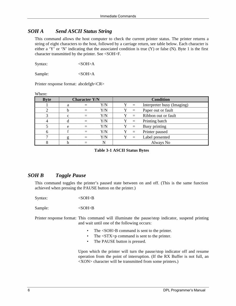
SOH A Send ASCII Status StringThis command allows the host computer to check the current printer status. The printer returns astring of eight characters to the host, followed by a carriage return, see table below. Each character iseither a ‘Y’ or ‘N’ indicating that the associated condition is true (Y) or false (N). Byte 1 is the firstcharacter transmitted by the printer. See <SOH>F.
Syntax: <SOH>A
Sample: <SOH>A
Printer response format: abcdefgh<CR>
Where:Byte Character Y/N Condition
1 a = Y/N Y = Interpreter busy (Imaging)2 b = Y/N Y = Paper out or fault3 c = Y/N Y = Ribbon out or fault4 d = Y/N Y = Printing batch5 e = Y/N Y = Busy printing6 f = Y/N Y = Printer paused7 g = Y/N Y = Label presented8 h = N Always No
Table 3-1 ASCII Status Bytes
SOH B Toggle PauseThis command toggles the printer’s paused state between on and off. (This is the same functionachieved when pressing the PAUSE button on the printer.)
Syntax: <SOH>B
Sample: <SOH>B
Printer response format: This command will illuminate the pause/stop indicator, suspend printingand wait until one of the following occurs:
• The <SOH>B command is sent to the printer.• The <STX>p command is sent to the printer.• The PAUSE button is pressed.
Upon which the printer will turn the pause/stop indicator off and resumeoperation from the point of interruption. (If the RX Buffer is not full, an<XON> character will be transmitted from some printers.)
Immediate Commands
DPL Programmer’s Manual 7
SOH C Stop/CancelThis command performs the same function as pressing the STOP/CANCEL button on the printer'sfront panel. This function clears the current label format from the print buffer, pauses the printer andilluminates the pause/stop indicator. (The pause condition is terminated as described under<SOH>B.)
Syntax: <SOH>C
SOH D SOH ShutdownThis commands the printer to ignore Immediate Commands (^A). The SOH shutdown command isrequired before loading graphic images or fonts because some may contain data sequences thatcould be interpreted as Immediate Commands.
Syntax: <SOH>D
After the SOH shutdown command is sent, Immediate Commands can be turned back on by sendinga valid SOH command three times, separated by a one second delay between each command, or bymanually resetting the printer. It is good practice to check batch quantities <SOH>E to verify that theSOH commands are working.
SOH E Send Batch QuantityThis command causes the printer to send back a 4-digit number indicating the quantity of labels leftto print in the current batch, followed by a carriage return. Communications latency may cause thisvalue to be higher than actual on some printers.
Syntax: <SOH>E
Sample: <SOH>E
Printer response: nnnn<CR>
Where: nnnn - Is four decimal digits, 0-9999.
Immediate Commands
8 DPL Programmer’s Manual
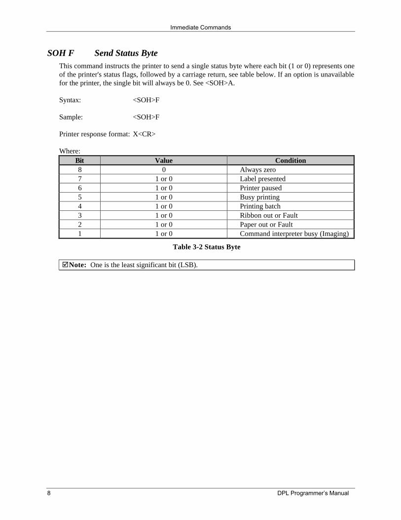
SOH F Send Status ByteThis command instructs the printer to send a single status byte where each bit (1 or 0) represents oneof the printer's status flags, followed by a carriage return, see table below. If an option is unavailablefor the printer, the single bit will always be 0. See <SOH>A.
Syntax: <SOH>F
Sample: <SOH>F
Printer response format: X<CR>
Where:Bit Value Condition8 0 Always zero7 1 or 0 Label presented6 1 or 0 Printer paused5 1 or 0 Busy printing4 1 or 0 Printing batch3 1 or 0 Ribbon out or Fault2 1 or 0 Paper out or Fault1 1 or 0 Command interpreter busy (Imaging)
Table 3-2 Status Byte
þNote: One is the least significant bit (LSB).
DPL Programmer’s Manual 9
4.0 System-Level Commands <STX>
System-Level Command FunctionsThe most commonly used commands are the System-Level Commands. These are used to load and storegraphic information, in addition to printer control. System-Level Commands are used to override defaultparameter values (fixed and selectable) and may be used before or after Immediate Commands butcannot be issued among Label-Formatting Commands. Selectable parameter values may be assigned viamenu selections or hardware (DIP switch) settings. If applicable, menu selectable parameters areprovided in the Operator’s Manual. System-Level Commands consist of:
1. Attention Getter, 0x02 or 0x7E, see Control Codes.
2. Command Character
3. Parameters (if any).
þNote: Refer to Appendix N for a listing of command applicability by printer before attempting touse the particular command.
STX A Set Time and DateThis command sets the time and date. The initial setting of the date will be stored in the printer'sinternal inch counter. This date can be verified by printing a configuration label.
Syntax: <STX>AwmmddyyyyhhMMjjj
Where:w 1 digit for day of week; 1 = Mondaymm 2 digits for monthdd 2 digits for dayyyyy 4 digits for yearhh 2 digits for hour in 24 hour formatMM 2 digits for minutesjjj 3 digits for Julian date / constant (see notes)
Sample: <STX>A1020319960855034
Printed response: Mon. Feb 3, 1996, 8:55AM, 034 (the 34th day of the year).
þNotes: When set to 000, the Julian date is automatically calculated. With values other than 000,the Julian date field of the <STX>B command and on the Configuration label will print asthat number, and will not increment daily. If factory defaults are restored the actual Juliandate will also be restored.
Printers equipped with menus may also set the time via the panel. Ovation! Printerswithout the Time/Date Option lose the time/date when power is removed.
Response format is variable, see Special Label-Formatting Command <STX>T>.
System-Level Commands
10 DPL Programmer’s Manual
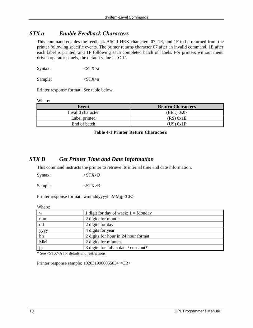
STX a Enable Feedback CharactersThis command enables the feedback ASCII HEX characters 07, 1E, and 1F to be returned from theprinter following specific events. The printer returns character 07 after an invalid command, 1E aftereach label is printed, and 1F following each completed batch of labels. For printers without menudriven operator panels, the default value is ‘Off’.
Syntax: <STX>a
Sample: <STX>a
Printer response format: See table below.
Where:Event Return Characters
Invalid character (BEL) 0x07Label printed (RS) 0x1EEnd of batch (US) 0x1F
Table 4-1 Printer Return Characters
STX B Get Printer Time and Date InformationThis command instructs the printer to retrieve its internal time and date information.
Syntax: <STX>B
Sample: <STX>B
Printer response format: wmmddyyyyhhMMjjj<CR>
Where:w 1 digit for day of week; 1 = Mondaymm 2 digits for monthdd 2 digits for dayyyyy 4 digits for yearhh 2 digits for hour in 24 hour formatMM 2 digits for minutesjjj 3 digits for Julian date / constant*
* See <STX>A for details and restrictions.
Printer response sample: 1020319960855034 <CR>
System-Level Commands
DPL Programmer’s Manual 11
STX b Set Cutter Signal Time
This command sets the cutter signal time (external), determining the low pulse length and delay timesetting. See below.
Syntax: <STX>bnnnn
Where: nnnn - 4 digits. (Low-delay time/µsec * 24)
Default Value: 3125 (75 msec)
For example, to set a low pulse, fifty-millisecond delay, first calculate the four-digit time:
0.050/0.000024 = 2083.33.
Sample: <STX>b2083
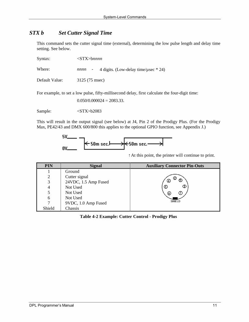
This will result in the output signal (see below) at J4, Pin 2 of the Prodigy Plus. (For the ProdigyMax, PE42/43 and DMX 600/800 this applies to the optional GPIO function, see Appendix J.)
↑At this point, the printer will continue to print.
PIN Signal Auxiliary Connector Pin-Outs1234567
Shield
GroundCutter signal24VDC, 1.5 Amp FusedNot UsedNot UsedNot Used9VDC, 1.0 Amp FusedChassis
Table 4-2 Example: Cutter Control - Prodigy Plus
System-Level Commands
12 DPL Programmer’s Manual
STX C Copy ModuleProdigy
The copy module command will halt all operation of the printer until the module copy function iscomplete. Be sure that the new module's write protect switch is turned ‘Off’ and the original modulehas the write protect switch ‘On’. Because there is only one module slot available, the followingprocedure must be followed to copy:
1. The pause indicator should begin blinking after the command is sent to the printer.
2. Insert the module to be copied at this time (data origin).
3. Press the PAUSE button to copy the module or the STOP/CANCEL button to abort.
4. When the pause indicator blinks again, remove the data origin module and insert the newmodule (data destination). If the paper/ribbon indicator is ‘On’, this indicates the origin modulecontents are being held in DRAM on the main board of the Prodigy.
5. Press the PAUSE button again and now the contents will be copied to the new module.
6. While the module is being loaded, the pause indicator will go ‘Off’. The paper/ribbon indicatorwill go ‘Off’ for a few seconds and then re-illuminate. At this point, the copied data is nowloaded in the new module.
þNote: The printer can copy a module without the use of this command. If you wish to copy agroup of modules, it can be done directly through the front panel. You can do this by firstpressing the STOP/CANCEL button and the FEED button simultaneously, then release bothand observe the blinking pause indicator. Follow the above procedure from Step 1.
Prodigy Plus
The copy module command will copy from module B (lower slot) to module A (upper slot). Bothmodules must be “Flash Modules”. While the data is being copied, the pause and the paper/ribbonindicators will toggle. When the copy is complete, the paper/ribbon indicators will stay ‘On’. Thiscommand will abort if there is data in module A. Be sure that module A is formatted before usingthis command and that the write protect switch is ‘Off’.
Syntax: <STX>C
Sample: <STX>qA<STX>C
This sample will clear and format Module A. The data will then be copied from module B to A.
System-Level Commands
DPL Programmer’s Manual 13
STX c Set Continuous Paper LengthThis command sets the page size (label length) for applications using continuous media. It disablesthe top-of-form function performed by the media sensor, however the sensor continues to monitorpaper-out conditions. See <STX>M.
Syntax: <STX>cnnnn
Where: nnnn - Is the length of the media feed for each label format, ininches/100 or millimeters/10 (see <STX>m).
Sample: <STX>c0100
The sample sets a page length of 100 (equaling 1.00 inch, assuming metric mode is not enabled).
þ Note: This command must be set to zero for edge or reflective media sensing operation.
STX D Memory Dump (Test Mode Only)Prodigy
For engineering purposes, this command dumps selected memory to RS-232 port in hex format;<ESC> terminates the mode. Test mode can be enabled via the DIP switches, see the Operator’sManual for more information.
Syntax: <STX>Dbbaaaa
Where: bb - System bank address
aaaa - Memory address, from 4000 to 7999
Sample: <STX>D074000<CR>
Printer response: A07 40000 4000 00 00 00 00 00 00 00 00 00 00 00 00 00 00 00 00 ...0 4010 00 00 00 00 00 00 00 00 00 00 00 00 00 00 00 00 ...0 4020 00 00 00 00 00 00 00 00 00 00 00 00 00 00 00 00 ...0 4030 00 00 00 00 00 00 00 00 00 00 00 00 00 00 00 00 ...
(Continued next page)
System-Level Commands
14 DPL Programmer’s Manual
STX D Memory Dump (Test Mode Only) continuedProdigy Plus / Allegro / Allegro 2
Syntax: <STX>Dbb(mm)aaaa
Where: bb - System bank address
mm - Module bank address if selected by system bank address. This isoptional and not used with EPROM or internal DRAM.
aaaa - Memory address (this must be between 4000 to 7FFF).
Sample: <STX>D074000<CR>
The sample allows viewing of the data in RAM #1, Bank 7, displayed in debug format. Pressing‘Enter’ will cause more data to be transmitted from the RS-232 port. Using PC Batch (version 5.0 orgreater) in dumb terminal mode, or use a dumb terminal to view the data. You must enter <ESC> toleave this mode and regain control of the printer.
þNote: The difference between the Prodigy Plus and Allegro is in the selection of the modulebank and the configuration of the EPROM.
STX d Set Printer to Double Buffer ModeThis enables double buffer mode. In this mode, when printing labels with incrementing fields (seeLabel-Formatting Commands) the printer will only erase and format those incremental fields, leavingthe rest of the label format untouched. This increases throughput. This command is only active if thelabels being printed are less than half the maximum size of the print buffer (see <STX>S).
Syntax: <STX>d
þNote:DMX600, DMX800, Ovation!, Ovation!2, PE42, PE43, Prodigy Max, S-Class 3210Series, Titan, and XL:
The <STX>d command is generally not used because fast formatting is the normaloperating mode when the number of variable print fields (Label-Formatting Commands +,-, <, >, u) is less than or equal to 1/3 of the total print field count. The <STX>d commandin this case will force fast formatting even when the proportion of variable print fields isgreater than 1/3 the total. The maximum label size is unaffected by this command. The<STX>s command restores normal (fast) formatting.
System-Level Commands
DPL Programmer’s Manual 15
STX E Set Quantity For Stored LabelThis sets a number of labels for printing using the format currently in the print buffer. (The printerautomatically stores the most recent format received in the buffer until the printer is reset or power isremoved.) This command, used in conjunction with the <STX>G command, will print the labels.
Syntax: <STX>Ennnn
Where: nnnn - A four-digit quantity, including leading zeros.
Sample: <STX>E0025<STX>G
The above sample will print 25 labels of the current label format in memory.
þNote: This command may be issued prior to formats not containing a specified quantity, seeQnnn.
STX e Select Edge SensorThis enables edge (transmissive) sensing for die-cut, and holed or notched media, allowing theprinter to detect a minimum gap of 0.1 inches (2.54mm) between labels. Labels must be at least ½inch (12.7mm) between each top-of-form, which is the point where printing of the new label willbegin. To line up the top-of-form with the printhead burnline, use the label offset command<STX>O. Printers without a menu default to this setting when powered up or reset.
Syntax: <STX>e
þNotes: This command will override the menu setting and is ignored when <STX>cnnnn isissued with a non-zero value for nnnn.
Use the <STX>r command to change from edge to reflective media sensing.
STX F Form FeedThis command feeds one label.
Syntax: <STX>F
þNote: Following a reset, if the length of the first label fed is less than the label offset value (asdefined by <STX>O), the printer will advance past this label until a top-of-form isdetected or the offset is reached.
System-Level Commands
16 DPL Programmer’s Manual
STX f Set Form Stop Position (Backfeed Command)This sets the stop position of the printed label, allowing the label to stop at a point past the start-of-print position. When the next label format is sent, the printer automatically withdraws (reverses) themedia to the start-of-print position. If quantities of more than one label are requested, the printer willoperate without backfeeding. Backfeed will then only occur when printing has stopped for a fewseconds.
Syntax: <STX>fnnn
Where: nnn - Is a three-digit distance from the sensor, in inches/100 or mm/10.This distance is independent of the start-of-print position(<STX>O), yet must be greater than the start-of-print position tohave take effect.
Sample: <STX>f230
The sample sets a stop position distance of 230, which equals 2.3 inches from the media sensor(unless in metric mode).
STX G Print Last Label FormatThis command prints a previously formatted label and restarts a canceled batch job following the lastprocessed label. This is used when there is a label format in the buffer. The <STX>E command isused to enter the quantity. (If the <STX>E command is not used only one label will print.)
Syntax: <STX>G
STX g Internal Batch Software ModeThis command instructs the printer to enter the Internal Batch Software Mode; a reset will return theprinter to default mode operation. The printer can also enter this mode via a menu selection onequipped units or by configuring the appropriate DIP switch on non-display models (however, areset will not return default mode operation.)
Syntax: <STX>g
þNote: See the Internal Batch Operator’s Manual (available at our website) for additionalinformation.
System-Level Commands
DPL Programmer’s Manual 17
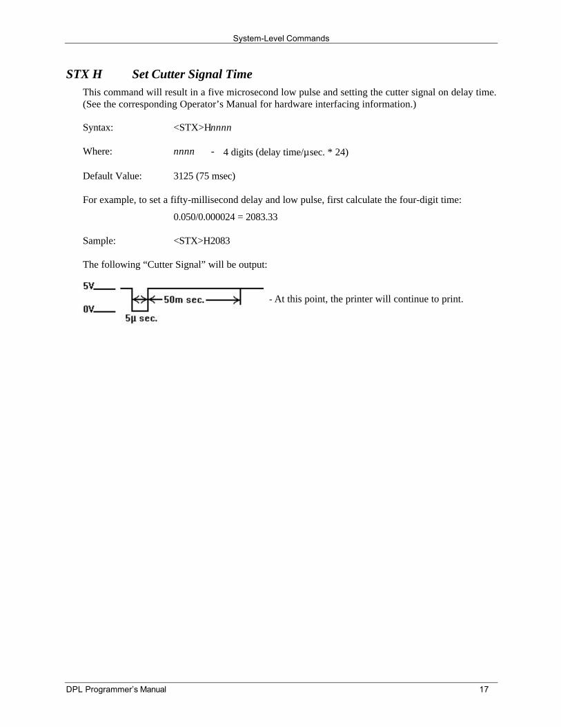
STX H Set Cutter Signal TimeThis command will result in a five microsecond low pulse and setting the cutter signal on delay time.(See the corresponding Operator’s Manual for hardware interfacing information.)
Syntax: <STX>Hnnnn
Where: nnnn - 4 digits (delay time/µsec. * 24)
Default Value: 3125 (75 msec)
For example, to set a fifty-millisecond delay and low pulse, first calculate the four-digit time:
0.050/0.000024 = 2083.33
Sample: <STX>H2083
The following “Cutter Signal” will be output:
At this point, the printer will continue to print.
System-Level Commands
18 DPL Programmer’s Manual
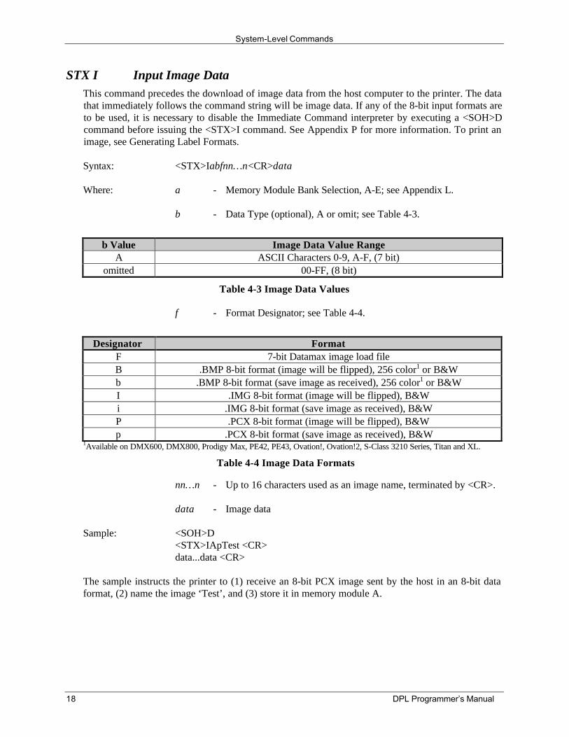
STX I Input Image DataThis command precedes the download of image data from the host computer to the printer. The datathat immediately follows the command string will be image data. If any of the 8-bit input formats areto be used, it is necessary to disable the Immediate Command interpreter by executing a <SOH>Dcommand before issuing the <STX>I command. See Appendix P for more information. To print animage, see Generating Label Formats.
Syntax: <STX>Iabfnn…n<CR>data
Where: a - Memory Module Bank Selection, A-E; see Appendix L.
b - Data Type (optional), A or omit; see Table 4-3.
b Value Image Data Value RangeA ASCII Characters 0-9, A-F, (7 bit)
omitted 00-FF, (8 bit)
Table 4-3 Image Data Values
f - Format Designator; see Table 4-4.
Designator FormatF 7-bit Datamax image load fileB .BMP 8-bit format (image will be flipped), 256 color1 or B&Wb .BMP 8-bit format (save image as received), 256 color1 or B&WI .IMG 8-bit format (image will be flipped), B&Wi .IMG 8-bit format (save image as received), B&WP .PCX 8-bit format (image will be flipped), B&Wp .PCX 8-bit format (save image as received), B&W
1Available on DMX600, DMX800, Prodigy Max, PE42, PE43, Ovation!, Ovation!2, S-Class 3210 Series, Titan and XL.
Table 4-4 Image Data Formats
nn…n - Up to 16 characters used as an image name, terminated by <CR>.
data - Image data
Sample: <SOH>D<STX>IApTest <CR>data...data <CR>
The sample instructs the printer to (1) receive an 8-bit PCX image sent by the host in an 8-bit dataformat, (2) name the image ‘Test’, and (3) store it in memory module A.
System-Level Commands
DPL Programmer’s Manual 19
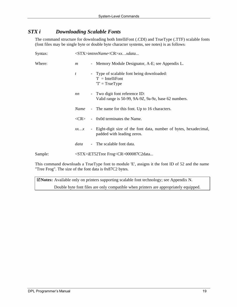
STX i Downloading Scalable FontsThe command structure for downloading both IntelliFont (.CDI) and TrueType (.TTF) scalable fonts(font files may be single byte or double byte character systems, see notes) is as follows:
Syntax: <STX>imtnnName<CR>xx…xdata...
Where: m - Memory Module Designator, A-E; see Appendix L.
t - Type of scalable font being downloaded:'I' = IntelliFont'T' = TrueType
nn - Two digit font reference ID:Valid range is 50-99, 9A-9Z, 9a-9z, base 62 numbers.
Name - The name for this font. Up to 16 characters.
<CR> - 0x0d terminates the Name.
xx…x - Eight-digit size of the font data, number of bytes, hexadecimal,padded with leading zeros.
data - The scalable font data.
Sample: <STX>iET52Tree Frog<CR>000087C2data...
This command downloads a TrueType font to module 'E', assigns it the font ID of 52 and the name"Tree Frog". The size of the font data is 0x87C2 bytes.
þNotes: Available only on printers supporting scalable font technology; see Appendix N.
Double byte font files are only compatible when printers are appropriately equipped.
System-Level Commands
20 DPL Programmer’s Manual
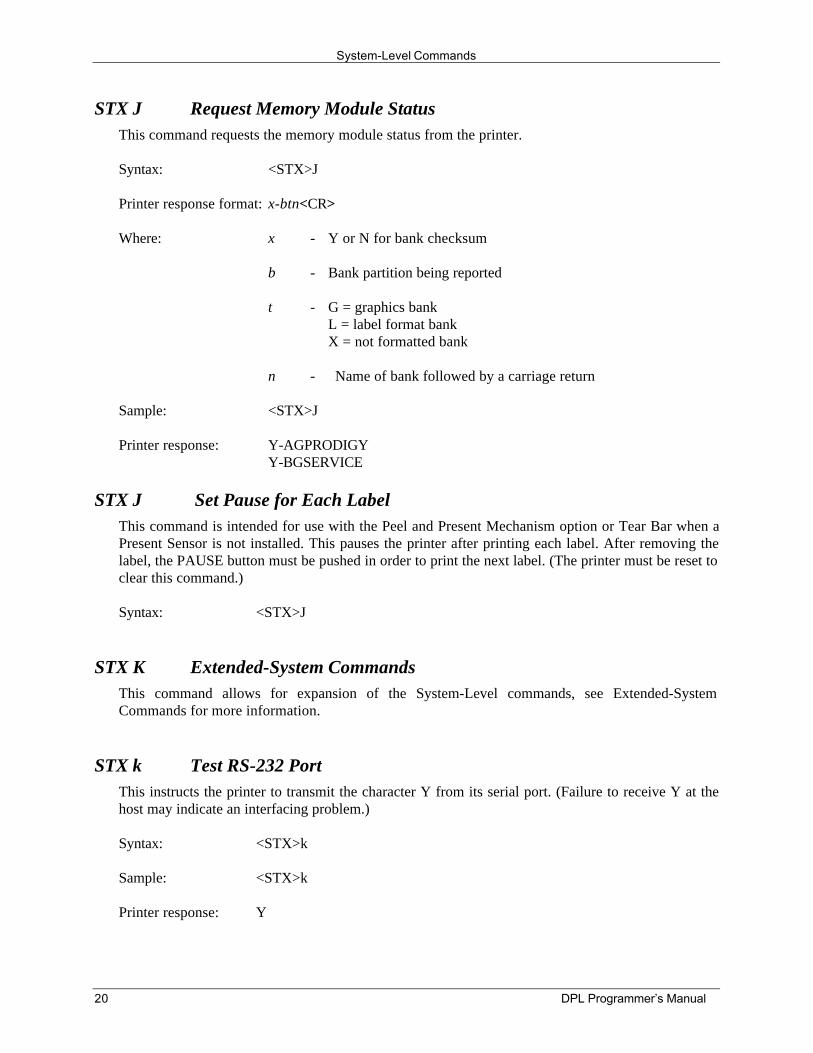
STX J Request Memory Module StatusThis command requests the memory module status from the printer.
Syntax: <STX>J
Printer response format: x-btn<CR>
Where: x - Y or N for bank checksum
b - Bank partition being reported
t - G = graphics bankL = label format bankX = not formatted bank
n - Name of bank followed by a carriage return
Sample: <STX>J
Printer response: Y-AGPRODIGYY-BGSERVICE
STX J Set Pause for Each LabelThis command is intended for use with the Peel and Present Mechanism option or Tear Bar when aPresent Sensor is not installed. This pauses the printer after printing each label. After removing thelabel, the PAUSE button must be pushed in order to print the next label. (The printer must be reset toclear this command.)
Syntax: <STX>J
STX K Extended-System CommandsThis command allows for expansion of the System-Level commands, see Extended-SystemCommands for more information.
STX k Test RS-232 PortThis instructs the printer to transmit the character Y from its serial port. (Failure to receive Y at thehost may indicate an interfacing problem.)
Syntax: <STX>k
Sample: <STX>k
Printer response: Y
System-Level Commands
DPL Programmer’s Manual 21
STX L Enter Label-Formatting CommandThis command switches the printer to the Label-Formatting Command input mode. Once in thismode, the printer expects to receive Record Structures and Label-Formatting Commands. Immediate,System-Level, and Font-Loading commands will be ignored until the label formatting mode isterminated with E, s, or X, (see Label-Formatting Commands for additional information).
Syntax: <STX>L
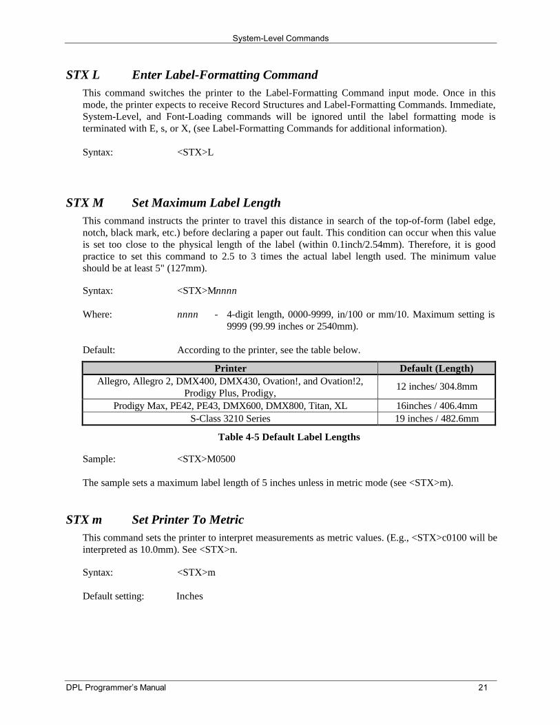
STX M Set Maximum Label LengthThis command instructs the printer to travel this distance in search of the top-of-form (label edge,notch, black mark, etc.) before declaring a paper out fault. This condition can occur when this valueis set too close to the physical length of the label (within 0.1inch/2.54mm). Therefore, it is goodpractice to set this command to 2.5 to 3 times the actual label length used. The minimum valueshould be at least 5" (127mm).
Syntax: <STX>Mnnnn
Where: nnnn - 4-digit length, 0000-9999, in/100 or mm/10. Maximum setting is9999 (99.99 inches or 2540mm).
Default: According to the printer, see the table below.
Printer Default (Length)Allegro, Allegro 2, DMX400, DMX430, Ovation!, and Ovation!2,
Prodigy Plus, Prodigy,12 inches/ 304.8mm
Prodigy Max, PE42, PE43, DMX600, DMX800, Titan, XL 16inches / 406.4mmS-Class 3210 Series 19 inches / 482.6mm
Table 4-5 Default Label Lengths
Sample: <STX>M0500
The sample sets a maximum label length of 5 inches unless in metric mode (see <STX>m).
STX m Set Printer To MetricThis command sets the printer to interpret measurements as metric values. (E.g., <STX>c0100 will beinterpreted as 10.0mm). See <STX>n.
Syntax: <STX>m
Default setting: Inches
System-Level Commands
22 DPL Programmer’s Manual
STX N Enter Internal Batch ModeThis command will cause the Prodigy printer to enter the Internal Batch Software operating modewithout the use of the DIP switch. To return to the standard operating mode, go to the ALT-S screen(dumb terminal) and enter 8. See <STX>g for other printers.
Syntax: <STX>N
þNote: See the Internal Batch Operator’s Manual (available at our website) for additionalinformation.
STX n Set Printer to InchesThis command sets the printer to interpret measurements in inches. (E.g., <STX>c0100 will beinterpreted as 1.00 inch.) See <STX>m.
Syntax: <STX>n
Default: Inch Mode
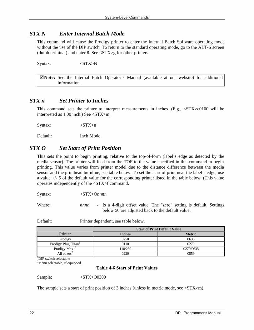
STX O Set Start of Print PositionThis sets the point to begin printing, relative to the top-of-form (label’s edge as detected by themedia sensor). The printer will feed from the TOF to the value specified in this command to beginprinting. This value varies from printer model due to the distance difference between the mediasensor and the printhead burnline, see table below. To set the start of print near the label’s edge, usea value +/- 5 of the default value for the corresponding printer listed in the table below. (This valueoperates independently of the <STX>f command.
Syntax: <STX>Onnnn
Where: nnnn - Is a 4-digit offset value. The "zero" setting is default. Settingsbelow 50 are adjusted back to the default value.
Default: Printer dependent, see table below.
Start of Print Default ValuePrinter Inches MetricProdigy 0250 0635
Prodigy Plus, Titan2 0110 0279Prodigy Max1,2 110/250 0279/0635
All others2 0220 05591DIP switch selectable2Menu selectable, if equipped.
Table 4-6 Start of Print Values
Sample: <STX>O0300
The sample sets a start of print position of 3 inches (unless in metric mode, see <STX>m).
System-Level Commands
DPL Programmer’s Manual 23
STX o Cycle CutterThis command will cause the (optional) cutter mechanism to immediately perform a cut. The Cuttermust be installed, enabled and the interlock closed for operation.
Syntax: <STX>o
STX P Character (Hex) Dump ModeThis command instructs the printer to enter the Character Hex Dump Mode (also known as ASCIIdump or monitor mode). Data sent to the printer following this command will be printed in rawASCII format. Labels must be at least 4 in. (102 mm) long and as wide as the print width. Thiscommand has the same effect as turning the printer ‘On’ while pressing the FEED button; however,in this case a Configuration and Test label will also be printed. To return to normal operation theprinter must be manually reset.
Syntax: <STX>P
STX p Controlled PauseThis controlled pause command will cause the printer to pause only after all previously receivedcommands are executed. This pause is often useful between batches of labels. This command willnot clear the pause condition (see <SOH>B).
Syntax: <STX>p
STX Q Clear All ModulesThis command instructs the printer to clear all Flash, RAM, and Internal Modules (see yourOperator's Manual for applicable options).
Syntax: <STX>Q
Prodigy - Clear 32K SRAM Module
This command will clear the specified memory bank of the Prodigy.
Syntax: <STX>QaCLEAR
Sample: a - Memory Module Bank, where:Where: A
BC
= A bank 16K= B bank 16K= Both banks 32K
Sample: <STX>QACLEAR
This command will clear bank A of the 32K SRAM module.
System-Level Commands
24 DPL Programmer’s Manual
STX q Clear ModuleThis command clears the selected memory module (Flash or RAM). If a module becomes corruptduring normal operations, it must be cleared. A corrupt module is identified when the printerresponds with a ‘No Modules Available’ message to the <STX>W command.
Syntax: <STX>qa
Where: a - Memory Module Designator, A-E; see Appendix L.
Sample: <STX>qA
The above sample clears memory module A.
þNotes: Turn ‘Off’ the write protect switch on Flash Modules before using this command.
If an image file is loaded improperly or is bad, the entire module may appear corrupt. Acorrupt Flash Module cannot be cleared with this command. To clear and reformat acorrupted module, place it in the module slot (for Prodigy Plus, this must be the ‘A’ slot)and cycle the printer power ‘Off’ and ‘On’.
If a module directory intermittently returns the message, ‘No Modules Available’, or ifdata continuously becomes corrupt when write protected, the module may be at the endof its service. Before concluding that a module is defective, cycle the power and test themodule.
STX R Remove Graphic ImageThis command allows the individual removal of a graphic image from the memory module.
Syntax: <STX>Rnn...n
Where: nn…n - Image name, eight characters maximum.
Sample: <STX>RLOGO<CR>
The sample removes the image ‘LOGO’ from the memory module.
System-Level Commands
DPL Programmer’s Manual 25
STX R Ribbon Saver On/OffThis is the only command used for the optional ribbon saver, enabling its operation. This does notinstruct the ribbon saver when to engage. The function is automatic, lifting when a minimum amountof label white space is exceeded. The ribbon saver will work continuously when enabled and inthermal transfer (ribbon) mode.
Syntax: <STX>Rx
Where: x - Y = Enabled (default)N = Disabled
Default: DIP switch or menu selection.
Sample: <STX>RN
The above sample clears memory module A.
þNote: This command is ignored on printers not equipped with the option.
STX r Select Reflective SensorThis command selects the reflective media sensor for label edge detection. Enable for sensingmaterials such as continuous tags or butt-cut media with a carbon-based black mark along theunderside. The end of the black mark will determine top-of-form. Labels must be at least 0.5"(13mm) between each TOF. Line up the start-of-print using the label offset command, <STX>O.The <STX>e command switches from reflective to edge sensing.
Syntax: <STX>r
Default: Edge sensing
STX S Set Feed RateThis command sets the printer’s media output rate when the FEED button is pressed.
Syntax: <STX>Sn
Where: n - Is a letter value from A to S (see Appendix M).
System-Level Commands
26 DPL Programmer’s Manual
STX STEST Test Module MemoryThis will test the 32K RAM module. Information stored on the module will be overwritten.
Syntax: <STX>STEST
Sample: <STX>STEST
Possible responses: Good: MODULE OK!!<CR><BEL>-or-
Bad: MODULE BAD!!<CR><BEL>
STX s Set Printer To Single Buffer ModeThis command instructs the printer to use single buffer mode. In this mode, the printer will eraseand format all fields. This, in turn, decreases printer throughput when incremental or replacementfields are used (see Label-Formatting Commands). See <STX>d.
Syntax: <STX>s
STX T Printhead Dot Pattern Test LabelThis command instructs the printer to print a dot pattern test label. This is the same test label printedwhen powering on the printer while pressing the FEED button, except that the printer will notproduce a Configuration Label and will not enter Character (Hex) Dump Mode. To view a full testpattern use media as wide as the print width and at least 2 inches (51mm) long.
Syntax: <STX>T
System-Level Commands
DPL Programmer’s Manual 27
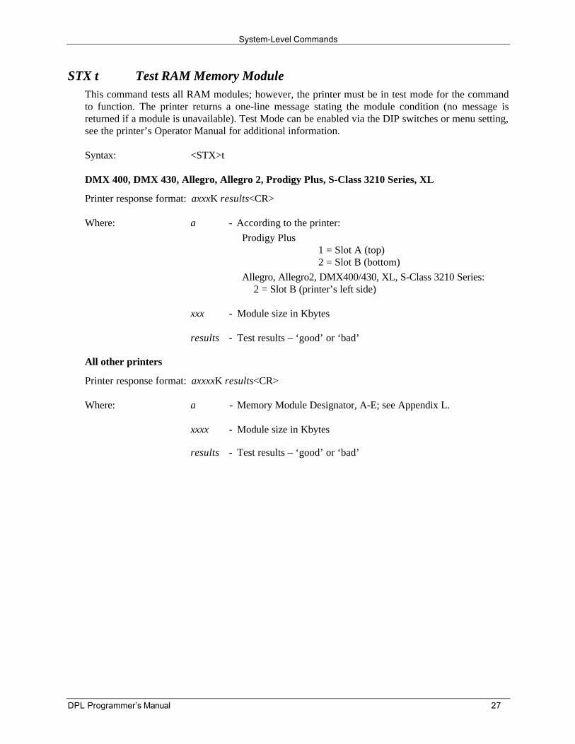
STX t Test RAM Memory ModuleThis command tests all RAM modules; however, the printer must be in test mode for the commandto function. The printer returns a one-line message stating the module condition (no message isreturned if a module is unavailable). Test Mode can be enabled via the DIP switches or menu setting,see the printer’s Operator Manual for additional information.
Syntax: <STX>t
DMX 400, DMX 430, Allegro, Allegro 2, Prodigy Plus, S-Class 3210 Series, XL
Printer response format: axxxK results<CR>
Where: a - According to the printer:Prodigy Plus
1 = Slot A (top)2 = Slot B (bottom)
Allegro, Allegro2, DMX400/430, XL, S-Class 3210 Series:2 = Slot B (printer’s left side)
xxx - Module size in Kbytes
results - Test results – ‘good’ or ‘bad’
All other printers
Printer response format: axxxxK results<CR>
Where: a - Memory Module Designator, A-E; see Appendix L.
xxxx - Module size in Kbytes
results - Test results – ‘good’ or ‘bad’
System-Level Commands
28 DPL Programmer’s Manual
STX U Label Format Field ReplacementThis command places new label data into format fields. Format fields are used to build a label. Thenew data string must equal the original string length and contain valid data. To easily keep track offields, place all of the fields to be updated with the command at the beginning of the label format. Amaximum of 99 format fields can be updated. Fields are numbered consecutively 01 to 99 in theorder received.
Syntax: <STX>Unnss…s<CR>
Where: nn - Is the format field number, 2 digits.
ss…s - Is the new string data, followed by a <CR>
Sample: <STX>L161100001000100data field 1<CR>161100001100110data field 2<CR>161100001200120data field 3<CR>Q0001E<STX>U01New data F1<CR><STX>U02New data F2<CR><STX>E0002<STX>G
The sample produces three labels. The first is formatted with the commands between <STX>L andE. The next two labels print with the replacement data contained in the <STX>U commands (see<STX>E and <STX>G).
System-Level Commands
DPL Programmer’s Manual 29
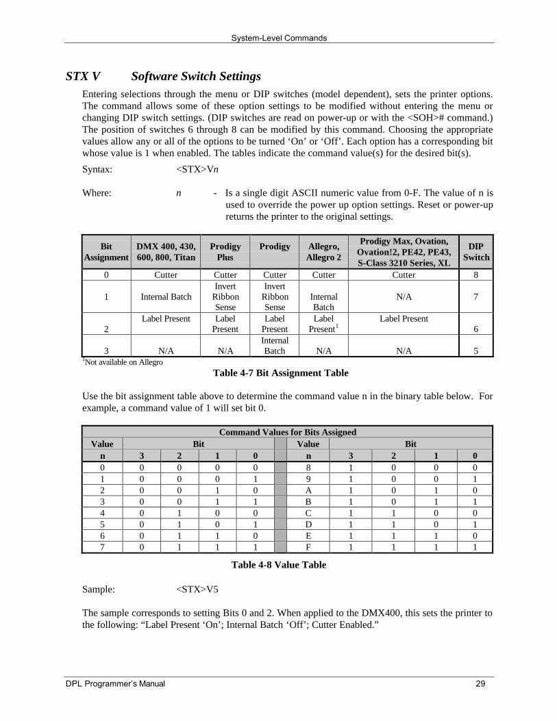
STX V Software Switch SettingsEntering selections through the menu or DIP switches (model dependent), sets the printer options.The command allows some of these option settings to be modified without entering the menu orchanging DIP switch settings. (DIP switches are read on power-up or with the <SOH># command.)The position of switches 6 through 8 can be modified by this command. Choosing the appropriatevalues allow any or all of the options to be turned ‘On’ or ‘Off’. Each option has a corresponding bitwhose value is 1 when enabled. The tables indicate the command value(s) for the desired bit(s).
Syntax: <STX>Vn
Where: n - Is a single digit ASCII numeric value from 0-F. The value of n isused to override the power up option settings. Reset or power-upreturns the printer to the original settings.
BitAssignment
DMX 400, 430,600, 800, Titan
ProdigyPlus
Prodigy Allegro,Allegro 2
Prodigy Max, Ovation,Ovation!2, PE42, PE43,S-Class 3210 Series, XL
DIPSwitch
0 Cutter Cutter Cutter Cutter Cutter 8
1 Internal BatchInvert
RibbonSense
InvertRibbonSense
InternalBatch
N/A 7
2Label Present Label
PresentLabel
PresentLabel
Present1Label Present
6
3 N/A N/AInternalBatch N/A N/A 5
1Not available on AllegroTable 4-7 Bit Assignment Table
Use the bit assignment table above to determine the command value n in the binary table below. Forexample, a command value of 1 will set bit 0.
Command Values for Bits AssignedValue Bit Value Bit
n 3 2 1 0 n 3 2 1 00 0 0 0 0 8 1 0 0 01 0 0 0 1 9 1 0 0 12 0 0 1 0 A 1 0 1 03 0 0 1 1 B 1 0 1 14 0 1 0 0 C 1 1 0 05 0 1 0 1 D 1 1 0 16 0 1 1 0 E 1 1 1 07 0 1 1 1 F 1 1 1 1
Table 4-8 Value Table
Sample: <STX>V5
The sample corresponds to setting Bits 0 and 2. When applied to the DMX400, this sets the printer tothe following: “Label Present ‘On’; Internal Batch ‘Off’; Cutter Enabled.”
System-Level Commands
30 DPL Programmer’s Manual
STX v Printer's Firmware Version InformationThis command causes the printer to send a version string. The version may be different from printerto printer (this data is the same as that printed on the configuration label).
Syntax: <STX>v
Printer response: VER DA - 01.01 12/21/93<CR>
STX W Request Memory Module InformationThis command requests a directory listing for memory module(s). Although a module can store font,graphics and format data together, it can display only one type of information at a time. If themodule contains all three types of data, it will be necessary to check the directory three times, usingeach of the control parameters, F, G, and L, to determine the contents.
Syntax: <STX>Wa
Where: a - Data type:
FGL
===
FontGraphicLabel
Sample: <STX>WG
Printer response: MODULE: A<CR>AVAILABLE BYTES IN MODULE: 00049083<CR>MODULE: B<CR>LOGO<CR>CAM<CR>AVAILABLE BYTES IN MODULE: 00257919<CR>
The response shows Module A contains no graphic data and has 49083 bytes of free space. ModuleB contains two graphic image files, LOGO and CAM with 257919 bytes remaining free.
System-Level Commands
DPL Programmer’s Manual 31
STX w Test Flash Memory ModuleThis command performs a test sequence on flash memory modules; however, the time for each testwill vary (from 20 seconds to two minutes), depending on the size of the module. The module musthave the write protect switch turned ‘Off’ for testing; all stored data will be destroyed.
DMX 400, DMX 430, Allegro, Allegro 2, Prodigy Plus
The printer responds with a list of 32 characters representing the programming and verification of 16banks of 16K of data. If only p's and v's are returned, all programmed data has been verified and theFlash Module is good. ‘E’ indicates a memory error, while ‘?’ indicates a hardware problem exists(within the module or interfacing hardware). Prodigy Plus’ must use the ‘A’ (top) slot for testing.
Syntax: <STX>w
Printer response format: aa…abb…b
Where: Any a (16 total) may be:
p?e
===
Program successHardware problemMemory error
and any b (16 total) may be:
v?e
===
Verify successHardware problemMemory error
Sample: <STX>w
Printer response: pp…pvv…v-or-
??…?-or-
ee…e
All other applicable printersThe printer responds with ‘good’ or ‘bad’ message results for each module tested. (No modulespresent will result in no response.)
Syntax: <STX>wa
Where: a - Memory Module Designator, A or B; see Appendix L.
Printer response format: Module a: xxxxK results
Where: a - Module tested.
xxxx - Module size in Kbytes
results - Test results – ‘good’ or ‘bad’
System-Level Commands
32 DPL Programmer’s Manual
STX X Set Default ModuleThe default module command is used when downloading information to a module memory and isdesigned to allow the user to select between modules. If ‘C’ is entered to select a memory bank, thedata will go to whichever bank was set by the Set Default Module command. If the printer uses onlyone bank, this command is not required.
Syntax: <STX>Xa
Where: a - Memory Module Designator, A-E; see Appendix L.
Sample: <STX>XB
The sample sets the default module to B.
The default module is one of the following:
1. The first alpha designator of existing modules if items 2 or 3 have not occurred.
2. The most recent module to be inserted while the power is on.
3. The module selected by this command.
þNote: Typically used prior to loading of PCL-4 bit-mapped fonts (see Font-LoadingCommands).
STX x Delete File from ModuleThis command removes a specific file from the specified module. The file name is removed from themodule directory and thus the file cannot be accessed. The actual storage space occupied by the fileis not released. To reclaim deleted file storage space (see <STX>z).
Syntax: <STX>xmtnn...n<CR>
Where: m - Memory Module Designator, A-E; see Appendix L.
t - The file type identification code:
GLFS
====
Graphic (Image) fileLabel format fileBit-Mapped font fileSmooth scaleable font file
nn...n - The file name to delete. Up to 16 characters for graphic or labelfiles. Three digits for bit-mapped font files and two digits forsmooth scalable font files.
System-Level Commands
DPL Programmer’s Manual 33
STX Y Output Sensor ValuesThis command causes the printer to respond with the sensor value status. The printer must be in testmode (via menu setting or DIP switches). When <STX>Y is received, the printer will respond withthe internal sensor values. To repeat the display of values, send the printer a ‘SPACE’ (20hexadecimal). Send <ESC> to terminate the function.
Syntax: <STX>Y
Printer response: Thermistor ADC: 0071 Reflective ADC:0000
Transmissive ADC: 0179 Paperout ADC: 0225
Battery Level: GOOD <CR>
Where: Paperout ADC: 0225 indicates paper is present;0000 indicates paper is not present.
Battery level: ‘Good’ indicates the battery has sufficient charge;‘Low’ indicates the battery is insufficiently charged
þNote: This format is somewhat different for all printers. Some require printer controlled papermovement for the media sensor to indicate a meaningful value.
STX y Select Font Symbol SetThis command selects the scalable font’s symbol set, which will remain active until another set isselected. See Appendices E and I, in addition to the <STX>KS command for more information.
Syntax: <STX>ySxx
Where: S - Byte size designation; see Appendix H.S = single byte symbol setsU = double byte symbol sets (equipped printers only)
xx - Symbol set selection.
Sample: <STX>ySPM
The sample selects the PC-850 multilingual set.
þNote: Only available on printers supporting scalable fonts, see Appendix N.
STX Z Print Internal Information and Dot PatternThis command prints configuration and dot pattern test labels. The results are similar to performingthe power up self-test, but the printer does not enter Character (Hex) Dump Mode. To capture allprinted information, use the labels as wide as the print width and at least 4 inches (102mm) long.
Syntax: <STX>Z
System-Level Commands
34 DPL Programmer’s Manual
STX z Pack ModuleThis command causes the printer to reclaim all storage space associated with all deleted files on thespecified module (see <STX>X and <STX>x). A Flash Module cannot be packed.
Syntax: <STX>zm
Where: m - Memory Module Designator, A-E; see Appendix L.
DPL Programmer’s Manual 35
5.0 Extended-System Commands <STX>K
Extended-System Command Functions
Extended-System Commands expand certain System-Level Commands providing extra printer control.The commands are issued in the same context as System-Level Commands.
þNote: Refer to Appendix N for a listing of command applicability by printer before attempting to usethe particular command.
STX K Offset Distance, Top-of-FormThis command provides for fine-adjustment of the start of print position (see <STX>O), to negatetolerances between multiple printers sharing label formats. Values approaching zero cause print tobegin nearer the leading edge. Large negative values may cause print to begin on the preceding label.This value is held in non-volatile memory for subsequent power-ups.
Syntax: <STX>Ksnn
Where: s - Minus sign (-) used for negative values only.
nn - 00 to 64 inches/100; in metric mode mm/10.
STX Kb Backfeed Time DelayThe backfeed time delay command controls the time a printed label is allowed to remain “presented”before retracting to the start of print position.
Syntax: <STX>Kbnnn<CR>
Where: nnn - Seconds/10
Extended-System Commands
36 DPL Programmer’s Manual
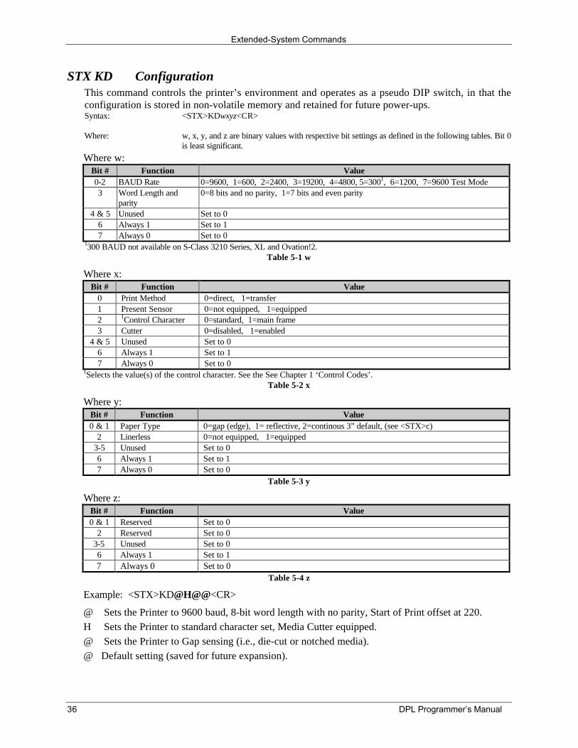
STX KD ConfigurationThis command controls the printer’s environment and operates as a pseudo DIP switch, in that theconfiguration is stored in non-volatile memory and retained for future power-ups.Syntax: <STX>KDwxyz<CR>
Where: w, x, y, and z are binary values with respective bit settings as defined in the following tables. Bit 0is least significant.
Where w:Bit # Function Value0-2 BAUD Rate 0=9600, 1=600, 2=2400, 3=19200, 4=4800, 5=3001, 6=1200, 7=9600 Test Mode3 Word Length and
parity0=8 bits and no parity, 1=7 bits and even parity
4 & 5 Unused Set to 06 Always 1 Set to 17 Always 0 Set to 0
1300 BAUD not available on S-Class 3210 Series, XL and Ovation!2.Table 5-1 w
Where x:Bit # Function Value
0 Print Method 0=direct, 1=transfer1 Present Sensor 0=not equipped, 1=equipped2 1Control Character 0=standard, 1=main frame3 Cutter 0=disabled, 1=enabled
4 & 5 Unused Set to 06 Always 1 Set to 17 Always 0 Set to 0
1Selects the value(s) of the control character. See the See Chapter 1 ‘Control Codes’.Table 5-2 x
Where y:Bit # Function Value0 & 1 Paper Type 0=gap (edge), 1= reflective, 2=continous 3” default, (see <STX>c)
2 Linerless 0=not equipped, 1=equipped3-5 Unused Set to 06 Always 1 Set to 17 Always 0 Set to 0
Table 5-3 y
Where z:Bit # Function Value0 & 1 Reserved Set to 0
2 Reserved Set to 03-5 Unused Set to 06 Always 1 Set to 17 Always 0 Set to 0
Table 5-4 z
Example: <STX>KD@H@@<CR>
@ Sets the Printer to 9600 baud, 8-bit word length with no parity, Start of Print offset at 220.H Sets the Printer to standard character set, Media Cutter equipped.@ Sets the Printer to Gap sensing (i.e., die-cut or notched media).@ Default setting (saved for future expansion).
Extended-System Commands
DPL Programmer’s Manual 37
STX Kf Set Present DistanceThis command specifies an additional amount to advance the label after print. This command has thesame effect as the set form stop position <STX>f, but specifies the distance to advance relative to thestart of print of the next label. The label’s advanced position, when set with <STX>Kf, is affected bythe set start of print position <STX>O command.
Syntax: <STX>Kfnnnn
Where: nnnn - A four-digit present distance in inches/100 or mm/10.
Sample: <STX>Kf0100
The sample represents a one-inch label advance unless in metric mode (see <STX>m).
STX KI GPIO InputThis command is used to configure the general purpose I/O input channels. It provides for externalcontrol of the printer via discrete lines. The PS, PRINT_START value for ff, for example, allows theuser to determine when label printing (paper movement) begins. (Label formatting generally beginswhen formatting data is received.) Through this command, a signal name is attached to a selected pinand a given signal characteristic as per the command syntax.
(Continued next page)
Extended-System Commands
38 DPL Programmer’s Manual
STX KI GPIO Input (continued)Syntax: <STX>KIff;p;s;a;www
Where: ff - 2-character function name (not case sensitive):
PS = PRINT_START (A label pending is allowed to print when theselected discrete input is enabled asconfigured.)
SB = START_BACK (A presented label is returned to the start ofprint position when the selected discreteinput is enabled as configured.)
For DPL / API Users:
I1 = USER_INPUT1
I2 = USER_INPUT2
.
.
.
.
.
.
.
.
. I8 = USER_INPUT8
p - 1 character pin number: 1 - 8
s - 1 character signal type, not case sensitive:
L = Level input, www = minimum time signal present, else ignore P = Positive pulsed input
N = Negative pulsed input
$ = AND inputs (pin number field specifies a bit mask)
+ = OR inputs (pin number specifies a bit mask)
a - 1 character active polarity:
0 = Active Low
1 = Active High
www - 3-digit pulse width 000..999
Sample: <STX>KIps;5;L;0;020<CR>
In the above sample, start of print will occur when input pin #5 remains low for at least 20 mS.
þNotes: All user input functions occur at a fixed periodic rate of one sample every 5 ms.
The pin number field bit masks are expressed in an ASCII decimal numeric representation.Each bit represents an input pin I1, I2…I8. All pins used in the bit mask will have thesame signal characteristics.
Extended-System Commands
DPL Programmer’s Manual 39
STX Ki SOH Command QueuingThis command specifies that SOH commands be (not) queued. Regardless of the state of thiscommand, SOH commands will be serviced. This command is used to avoid situations where SOHcommands queue up during label formatting. In these circumstances there may be printing delaysduring the de-queuing of the commands. Some host software programs demand status responses ofthe printer that cannot be immediately de-queued resulting in the above situation. The defaultcondition is queuing enabled
Syntax: <STX>Kia
Where: a - Y = queuing enabledN = queuing disabled
Sample: <STX>KiN
The above sample results in SOH commands queuing to be disabled.
STX KM Memory ConfigurationThis system-level command specifies the configuration of the printer's available internal DRAMmemory. The internal DRAM memory is inclusive of the standard DRAM and any additionaloptional DRAM installed. This command provides a method for managing internal memoryconfiguration of the printer. Memory can be assigned to specific entities or functions in units of 4KBblocks. The configuration is stored in non-volatile memory and is reinstated upon a power-up orreset of the printer. If the total requested memory allocation exceeds the configurable memoryavailable, the command will be rejected and the printer will assume its previous memoryconfiguration.
A memory configuration command that contains no fields causes the memory configuration to beleft as is. Any internal memory configurations not specified by the command results in ‘No Changes’to those configurations. The printer executes the memory configuration specified by the commandduring the next idle period following its receipt.
The query memory configuration command <STX>KQ will provide the label print buffer space-available information. The memory allocation(s) as set by this command, draw from the samememory pool, affecting maximum print length and throughput.
(Continued next page)
Extended-System Commands
40 DPL Programmer’s Manual
STX KM Memory Configuration (continued)Syntax: <STX>Kix[:jy][:kz]<CR>
Where: i, j, k are M, S, or W as described in the following paragraphs. x, y, z are four-digitmaximum number of 4K byte blocks or in/100 or (mm/10) as described below.
Any of the three fields is optional and are separated by the colon. Brackets indicateoptional fields.
M This represents the start of a sequence (up to five characters), that assigns memory to theinternal memory module. If this field does not appear, then the internal memory moduleis not affected. If no internal memory module exists, it will be created and formatted. Ifthe internal memory module already exists, it will be erased, re-sized and formatted. Thenumber that follows the M is a decimal number (up to four digits) that specifies the sizeof memory in 4KB blocks, to assign to the internal memory module. A value of "0000"will delete the internal memory module, (see Appendix L for additional information).
S Represents the start of a sequence (up to five characters), that assigns the amount ofinternal memory allocated to the smooth scalable font processor. This field is optionaland if it does not appear, the current amount of memory assigned to the smooth scalablefont processor is left unchanged. This must be at least 15 to print scalable fonts, 60 forKanji fonts. The number that follows the S is a decimal number (up to four digits) thatspecifies the size of memory, in 4 KB blocks, to assign to the smooth scalable fontprocessor. The minimum requirement is 0015 (60KB). Any value less, results in theamount of memory assigned to be zero (0000) and disables the printing of smoothscalable fonts. The recommended value is 0025 (100KB).
W Represents the start of a sequence, (up to five characters), that sets the printable labelwidth. Setting a width smaller than the natural (maximum) width of the printer effectivelyextends printable label length. This field is optional and if it does not appear, the currentprintable label width is left unchanged. The number that follows the W is a decimalnumber (up to four digits) that specifies the printable label width in either 100th's ofinches or millimeters, depending on the current units setting of the printer (English orMetric). If the value specified exceeds the natural (maximum) width of the printer, theprintable label width is set to its maximum. If the value specified is less than theminimum value allowed, then the printable label width is set to the minimum allowedvalue. The minimum allowed value is 200 and maximum value is the maximum printerwidth.
Only one field M, S, or W is required, any two fields are separated with a colon asshown.
Label printing requirements may be computed as bytes (label print length * widthallocation * printhead resolution/8). For maximum throughput, the memory allocatedshould allow for a minimum of three times the computed requirement or available thelabel length as determined by <STX>KQ should be three times the label print length.
Sample: <STX>KM0020:S0015<CR>
In the sample, memory is allocated 20*4*1024 bytes for module space and 15*4*1024 bytes forscalable cache.
Extended-System Commands
DPL Programmer’s Manual 41
Extended-System Commands
42 DPL Programmer’s Manual
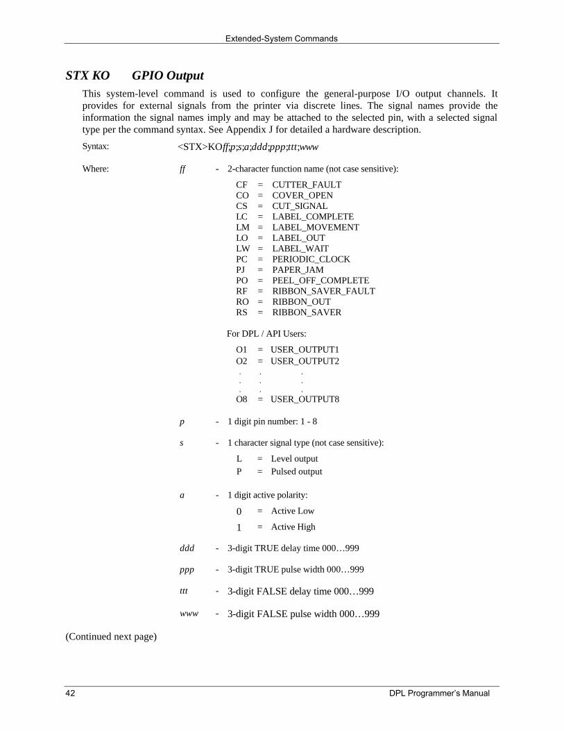
STX KO GPIO OutputThis system-level command is used to configure the general-purpose I/O output channels. Itprovides for external signals from the printer via discrete lines. The signal names provide theinformation the signal names imply and may be attached to the selected pin, with a selected signaltype per the command syntax. See Appendix J for detailed a hardware description.
Syntax: <STX>KOff;p;s;a;ddd;ppp;ttt;www
Where: ff - 2-character function name (not case sensitive):
CFCOCSLCLMLOLWPCPJPORFRORS
=============
CUTTER_FAULTCOVER_OPENCUT_SIGNALLABEL_COMPLETELABEL_MOVEMENTLABEL_OUTLABEL_WAITPERIODIC_CLOCKPAPER_JAMPEEL_OFF_COMPLETERIBBON_SAVER_FAULTRIBBON_OUTRIBBON_SAVER
For DPL / API Users:
O1 = USER_OUTPUT1 O2 = USER_OUTPUT2
.
.
.
.
.
.
.
.
. O8 = USER_OUTPUT8
p - 1 digit pin number: 1 - 8
s - 1 character signal type (not case sensitive):
L = Level output P = Pulsed output
a - 1 digit active polarity:
0 = Active Low
1 = Active High
ddd - 3-digit TRUE delay time 000…999
ppp - 3-digit TRUE pulse width 000…999
ttt - 3-digit FALSE delay time 000…999
www - 3-digit FALSE pulse width 000…999
(Continued next page)
Extended-System Commands
DPL Programmer’s Manual 43
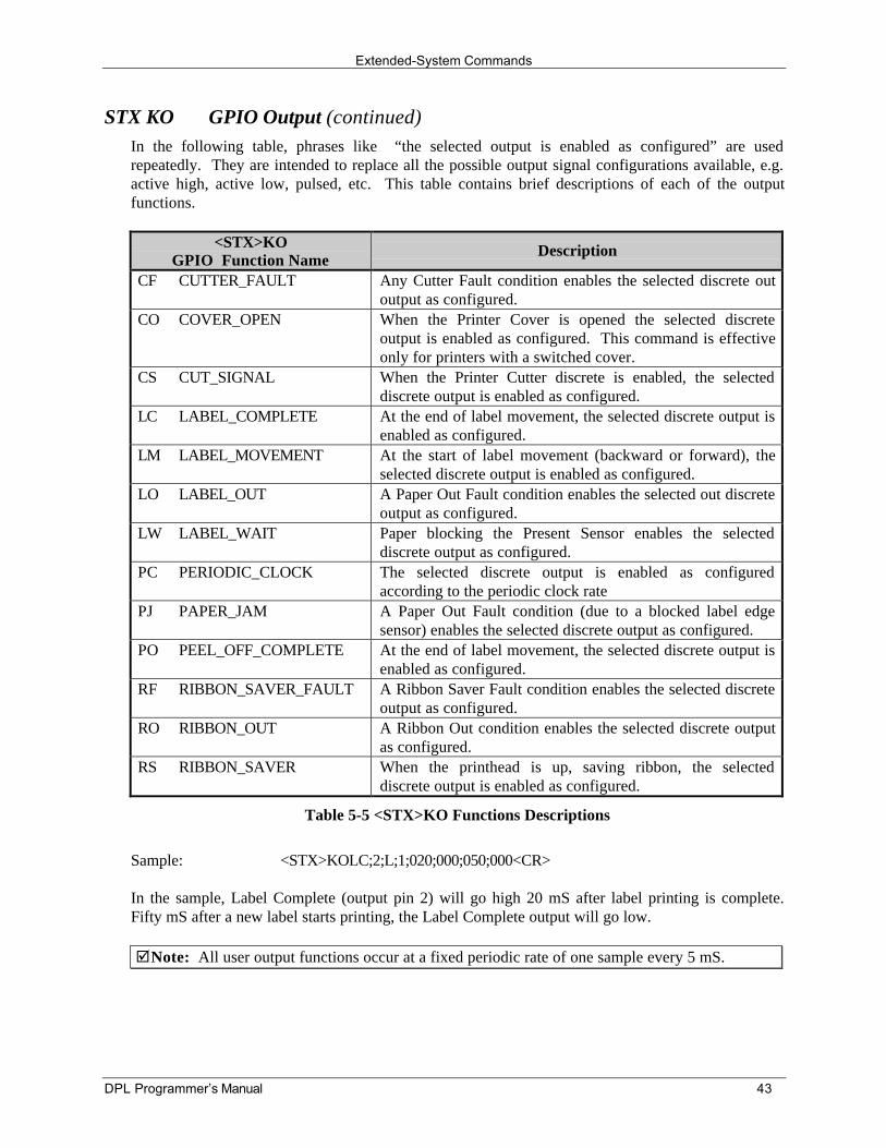
STX KO GPIO Output (continued)In the following table, phrases like “the selected output is enabled as configured” are usedrepeatedly. They are intended to replace all the possible output signal configurations available, e.g.active high, active low, pulsed, etc. This table contains brief descriptions of each of the outputfunctions.
<STX>KOGPIO Function Name
Description
CF CUTTER_FAULT Any Cutter Fault condition enables the selected discrete outoutput as configured.
CO COVER_OPEN When the Printer Cover is opened the selected discreteoutput is enabled as configured. This command is effectiveonly for printers with a switched cover.
CS CUT_SIGNAL When the Printer Cutter discrete is enabled, the selecteddiscrete output is enabled as configured.
LC LABEL_COMPLETE At the end of label movement, the selected discrete output isenabled as configured.
LM LABEL_MOVEMENT At the start of label movement (backward or forward), theselected discrete output is enabled as configured.
LO LABEL_OUT A Paper Out Fault condition enables the selected out discreteoutput as configured.
LW LABEL_WAIT Paper blocking the Present Sensor enables the selecteddiscrete output as configured.
PC PERIODIC_CLOCK The selected discrete output is enabled as configuredaccording to the periodic clock rate
PJ PAPER_JAM A Paper Out Fault condition (due to a blocked label edgesensor) enables the selected discrete output as configured.
PO PEEL_OFF_COMPLETE At the end of label movement, the selected discrete output isenabled as configured.
RF RIBBON_SAVER_FAULT A Ribbon Saver Fault condition enables the selected discreteoutput as configured.
RO RIBBON_OUT A Ribbon Out condition enables the selected discrete outputas configured.
RS RIBBON_SAVER When the printhead is up, saving ribbon, the selecteddiscrete output is enabled as configured.
Table 5-5 <STX>KO Functions Descriptions
Sample: <STX>KOLC;2;L;1;020;000;050;000<CR>
In the sample, Label Complete (output pin 2) will go high 20 mS after label printing is complete.Fifty mS after a new label starts printing, the Label Complete output will go low.
þNote: All user output functions occur at a fixed periodic rate of one sample every 5 mS.
Extended-System Commands
44 DPL Programmer’s Manual
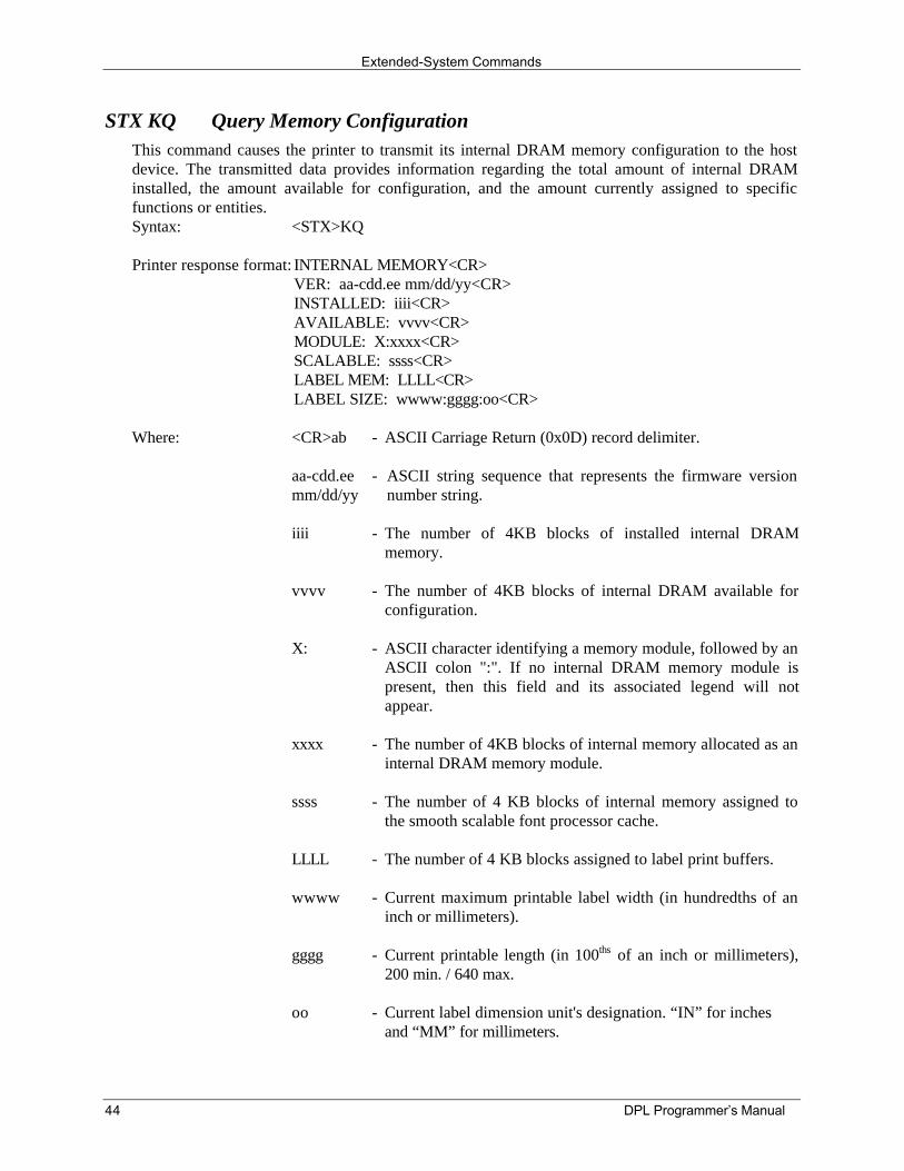
STX KQ Query Memory ConfigurationThis command causes the printer to transmit its internal DRAM memory configuration to the hostdevice. The transmitted data provides information regarding the total amount of internal DRAMinstalled, the amount available for configuration, and the amount currently assigned to specificfunctions or entities.Syntax: <STX>KQ
Printer response format: INTERNAL MEMORY<CR>VER: aa-cdd.ee mm/dd/yy<CR>INSTALLED: iiii<CR>AVAILABLE: vvvv<CR>MODULE: X:xxxx<CR>SCALABLE: ssss<CR>LABEL MEM: LLLL<CR>LABEL SIZE: wwww:gggg:oo<CR>
Where: <CR>ab - ASCII Carriage Return (0x0D) record delimiter.
aa-cdd.eemm/dd/yy
- ASCII string sequence that represents the firmware versionnumber string.
iiii - The number of 4KB blocks of installed internal DRAMmemory.
vvvv - The number of 4KB blocks of internal DRAM available forconfiguration.
X: - ASCII character identifying a memory module, followed by anASCII colon ":". If no internal DRAM memory module ispresent, then this field and its associated legend will notappear.
xxxx - The number of 4KB blocks of internal memory allocated as aninternal DRAM memory module.
ssss - The number of 4 KB blocks of internal memory assigned tothe smooth scalable font processor cache.
LLLL - The number of 4 KB blocks assigned to label print buffers.
wwww - Current maximum printable label width (in hundredths of aninch or millimeters).
gggg - Current printable length (in 100ths of an inch or millimeters),200 min. / 640 max.
oo - Current label dimension unit's designation. “IN” for inchesand “MM” for millimeters.
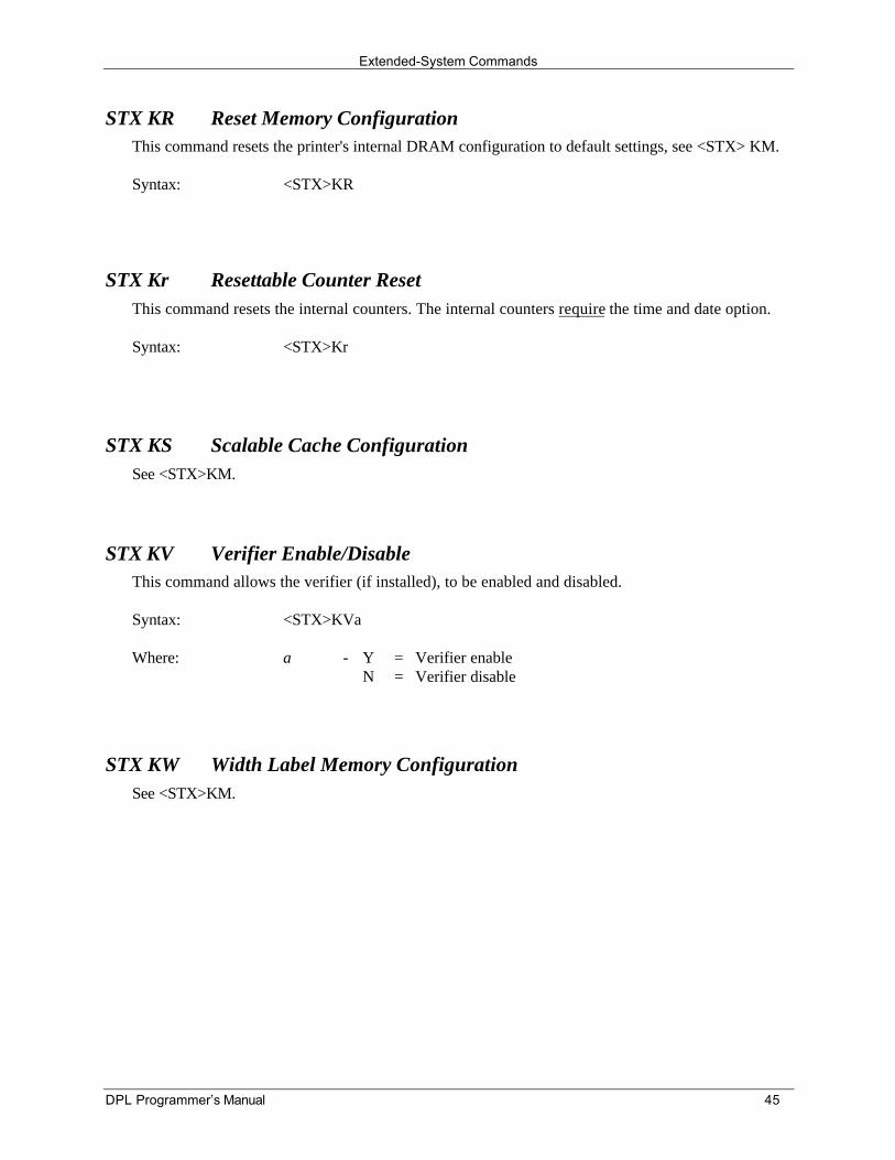
Extended-System Commands
DPL Programmer’s Manual 45
STX KR Reset Memory ConfigurationThis command resets the printer's internal DRAM configuration to default settings, see <STX> KM.
Syntax: <STX>KR
STX Kr Resettable Counter ResetThis command resets the internal counters. The internal counters require the time and date option.
Syntax: <STX>Kr
STX KS Scalable Cache ConfigurationSee <STX>KM.
STX KV Verifier Enable/DisableThis command allows the verifier (if installed), to be enabled and disabled.
Syntax: <STX>KVa
Where: a - YN
==
Verifier enableVerifier disable
STX KW Width Label Memory ConfigurationSee <STX>KM.
DPL Programmer’s Manual 46
6.0 Label-Formatting Commands
Label-Formatting Command Functions
An <STX>L command switches the printer from the System-Level to the Label-Formatting Commandprocessor. All commands following the <STX>L are interpreted as label formatting commands. Label-Formatting Commands can be used to override default parameter values. Selectable parameter valuedefaults may be assigned via the menu selection on printers so equipped. Menu-selectable parameters areshown in the printer Operator’s Manual. Label formats that contain no commands overriding printerdefault values will assume the defaults.
þNote: Refer to Appendix N for a listing of command applicability by printer before attempting to usethe particular command.
: Set Cut By AmountThis command allows a predetermined number of labels to be printed before a cut is initiated. Thisfeature is useful when it is necessary to print an uncut strip of labels. Between 1 and 9999 labels maybe printed before a cut is made. The amount must be smaller than the quantity of labels printed. Theprinter default is one.
Syntax: :nnnn
Where: nnnn - Is a four digit decimal number indicating the number of labels tobe printed before performing a cut.
Sample: <STX>L<CR>:0005<CR>141100001000100SAMPLE LABEL<CR>Q0021<CR>E<CR>
The sample instructs the printer to make a cut after labels 5, 10, and 20 have been printed. Label 21will be cut at the start of a subsequent label format (batch) unless a default (cut by amount) greaterthan one (1) has been entered via the menu on equipped models.
þNote: The cutter must be enabled and the cutter interlock closed for operation.
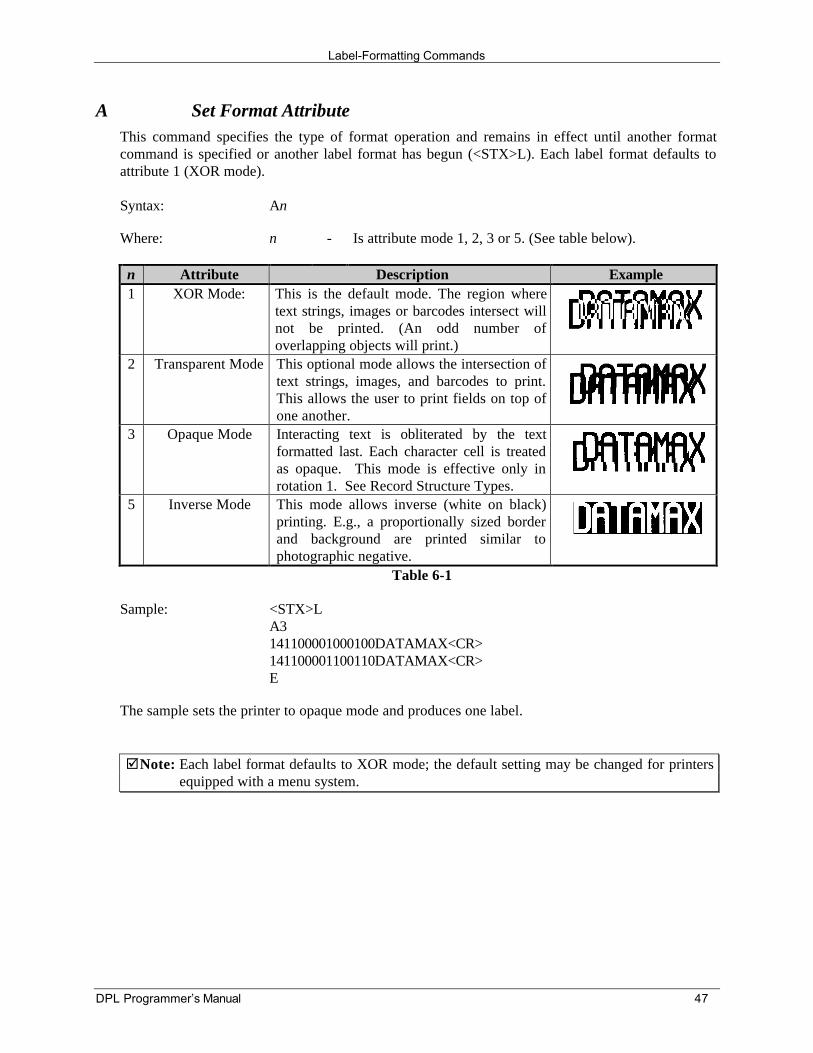
Label-Formatting Commands
DPL Programmer’s Manual 47
A Set Format AttributeThis command specifies the type of format operation and remains in effect until another formatcommand is specified or another label format has begun (<STX>L). Each label format defaults toattribute 1 (XOR mode).
Syntax: An
Where: n - Is attribute mode 1, 2, 3 or 5. (See table below).
n Attribute Description Example1 XOR Mode: This is the default mode. The region where
text strings, images or barcodes intersect willnot be printed. (An odd number ofoverlapping objects will print.)
2 Transparent Mode This optional mode allows the intersection oftext strings, images, and barcodes to print.This allows the user to print fields on top ofone another.
3 Opaque Mode Interacting text is obliterated by the textformatted last. Each character cell is treatedas opaque. This mode is effective only inrotation 1. See Record Structure Types.
5 Inverse Mode This mode allows inverse (white on black)printing. E.g., a proportionally sized borderand background are printed similar tophotographic negative.
Table 6-1
Sample: <STX>LA3141100001000100DATAMAX<CR>141100001100110DATAMAX<CR>E
The sample sets the printer to opaque mode and produces one label.
þNote: Each label format defaults to XOR mode; the default setting may be changed for printersequipped with a menu system.
Label-Formatting Commands
48 DPL Programmer’s Manual
C Set Column Offset AmountThis command allows horizontal adjustment of the point where printing begins. This feature isuseful when a single format must be printed on several different types of labels that contain pre-printed information. (If the pre-printed data does not appear in the same place on every label, thenew data may overlap the pre-printed data.) The ‘C’ command instructs the printer to print labelformats nnnn units to the right of the position that the format specifies.
Syntax: Cnnnn
Where: nnnn - Is a four-digit number for the column offset, inches /100 ormm/10. The printer default is 0 for offset.
Sample: <STX>LC0050141100001000100DATAMAX<CR>
The sample shifts all format data 0.5 inches to the right, unless the printer is in metric mode (seeLabel-Formatting Command ‘m’).
c Set Cut By AmountThis command is the same as the Set Cut By Amount (:) command except only a two-digit value canbe entered. This command allows a predetermined number of labels to be printed before a cut ismade. 1 to 99 labels may be printed before a cut is made. The printer default is one.
Syntax: cnn
Where: nn - Is a two-digit number indicating the number of labels to be printedbefore performing a cut.
Sample: <STX>L<CR>c07<CR>141100001000100SAMPLE LABEL<CR>Q0021<CR>E
The sample instructs the printer to make a cut after labels 7, 14, and 21 have been printed.
þNote: The cutter must be enabled and the cutter interlock closed for operation.
Label-Formatting Commands
DPL Programmer’s Manual 49
D Set Width and Height Dot SizeThis command is used to change the size of a printed dot, hence the print resolution in dots per inch(DPI) of the printer. By changing the height of a dot, the maximum length of a label can be increasedor decreased. The table below lists the step sizes available.
Syntax: Dwh
Where: w - Is Dot Width multiplier 1 or 2.
h - Is Dot Height multiplier 1, 2, or 3.
Dot SizePrinthead Resolution (DPI)Inches Millimeters
203 . 0049 .125300 .0033 .085152 .0066 .167
289 (DMX 430 only) .0035 .088
Table 6-1 Printhead Dot Sizes
þNote: Default is D22 for all 203 DPI printers and D11 for 300 DPI printers. The default may bechanged on menu equipped printers.
E Terminate Label Formatting Mode and Print LabelWhen the printer is processing Label-Formatting Commands and receives an ‘E’ command, it willimmediately print a label based on the data received up to that point. Even if no printable data hasbeen received, the printer will generate and feed a label (other termination commands are ‘X’ and‘s’). Commands sent to the printer after a “terminate label” command must be Immediate, System-Level or Font Download type.
Syntax: E
Sample: <STX>L<CR>121100000000000Testing<CR>E<CR>
The sample label format will print one label.
Label-Formatting Commands
50 DPL Programmer’s Manual
G Place Data in Global RegisterThe ‘G’ command saves the print data of a print format record in a global register (temporarystorage). This data may be retrieved and copied to another record in the same label format using thespecial Label-Formatting Command, <STX>S. Global registers are named in the order received,beginning with register A, ending at register P, and incrementing with each instance of the Gcommand use.
Syntax: G
Sample: <STX>L<CR>121100000000000Testing<CR>G<CR>1A2210001000000<STX>SA<CR>E<CR>
The sample stores, retrieves and prints the data in global register A. One label is printed with “Testing” in two locations.
H Enter Heat SettingThis command changes the "on time" of the printhead elements. The default setting is 10 (except inthe case of printers with a menu, where the default setting can be changed through the keypad). Anincrease or decrease in this value results in a change of heat applied by the printhead to the media,lightening or darkening the print contrast accordingly. This is helpful when using different mediatypes, each requiring a different amount of heat to properly image the media. The host device cansend this command value to correct the heat setting per the application.
Syntax: Hnn
Where: nn - Is a two-digit heat value, 00-20* (see note below).
Sample: <STX>L<CR>H15<CR>141100001000100SAMPLE LABEL<CR>E
The sample sets the printer for a heat value of 15 and prints one label.
þNotes: *PE42, PE43, Prodigy Max, Ovation!, Ovation!2, S-Class 3210 Series, Titan, and XL have amaximum value of 30.
The Darkness Potentiometer on printers without a menu and the “Darkness” menu function onprinters with menu is intended for use in matching print contrast levels following a printheadreplacement. (It has very little control over the actual burn temperature used for imaging.)
The printer automatically compensates for varying print speed by internally adjusting heat (with theexception of the Ovation!s, see below). Higher speeds result in the maximum heat even with heatsettings less than 30, depending on the darkness setting and the direct-thermal setting.
Ovation! and Ovation!2 heat settings can affect print speeds. Heat settings above 20 will limit printspeeds to 1.0 and 1.5 inches per second for Direct Thermal and Thermal Transfer (ribbon) modesrespectively. Heat settings above 25 will limit print speed to 1.0 IPS in Thermal Transfer mode.
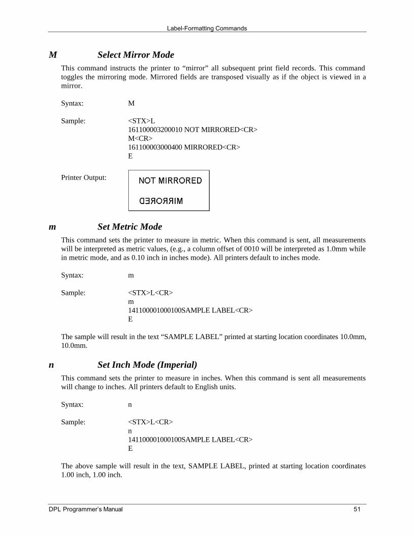
Label-Formatting Commands
DPL Programmer’s Manual 51
M Select Mirror ModeThis command instructs the printer to “mirror” all subsequent print field records. This commandtoggles the mirroring mode. Mirrored fields are transposed visually as if the object is viewed in amirror.
Syntax: M
Sample: <STX>L161100003200010 NOT MIRRORED<CR>M<CR>161100003000400 MIRRORED<CR>E
Printer Output:
m Set Metric ModeThis command sets the printer to measure in metric. When this command is sent, all measurementswill be interpreted as metric values, (e.g., a column offset of 0010 will be interpreted as 1.0mm whilein metric mode, and as 0.10 inch in inches mode). All printers default to inches mode.
Syntax: m
Sample: <STX>L<CR>m141100001000100SAMPLE LABEL<CR>E
The sample will result in the text “SAMPLE LABEL” printed at starting location coordinates 10.0mm,10.0mm.
n Set Inch Mode (Imperial)This command sets the printer to measure in inches. When this command is sent all measurementswill change to inches. All printers default to English units.
Syntax: n
Sample: <STX>L<CR>n141100001000100SAMPLE LABEL<CR>E
The above sample will result in the text, SAMPLE LABEL, printed at starting location coordinates1.00 inch, 1.00 inch.
Label-Formatting Commands
52 DPL Programmer’s Manual
P Set Print SpeedThis command sets a print speed for a label or batch of labels. See Appendix M for valid ranges.
Syntax: Pa
Where: a - Is a single character (A to P) representing a speed.
Sample: <STX>LPC141100001000100LABEL1<CR>E<STX>L141100001000100LABEL2>CR>E
The sample prints two labels, the first at a speed of 3.0 inches per second (76 mm per second) andthe second at the printer default.
p Set Label Backup SpeedThis command is used with the “Peel and Present” and “Cut Label” operations”. It allows the user tospecify the rate at which the printer will reverse to align the label to the next start of print position.The rate set remains in effect until another backup speed command is received. The rate is modifiedvia the menu setting (if equipped) or when the printer is reset. See Appendix M for valid ranges.
Syntax: pa
Where: a - Is a single character (C to I) representing a speed.
Sample: <STX>LpF
The above sample sets the printer to a backup speed of 3.5 IPS.
Q Set Quantity Of Labels To PrintThis command sets the number of the label copies to be printed. All printers default to 1.
Syntax: Qnnnn
Where: nnnn - Is a four-digit value setting for the number of labels to be printed.
Sample: <STX>L121100000000000Testing<CR>Q0020<CR>E<CR>
The above sample will print a batch of 20 identical labels.
Label-Formatting Commands
DPL Programmer’s Manual 53
R Set Row Offset AmountThis command allows vertical adjustment of the point where printing begins. This is useful when asingle format is printed on several different types of labels that contain pre-printed information.However, if the pre-printing does not appear in the same place on every label, data may overprint thepre-printed areas. The ‘R’ command instructs the printer to print label formats ‘nnnn’ incrementsabove the position the format specifies. Valid input values are numbers between 0000 and 9999,(refer to the C, Set Column Offset Amount Command.)
Syntax: Rnnnn
Where: nnnn - Is a four-digit offset 0000-9999, inches/100 or millimeters/10.
Sample: <STX>LR0037<CR>141100001000100SAMPLE LABEL<CR>E
The sample sets the printer's offset row amount to 37 hundredths of an inch (unless in metric mode).
r Recall Stored Label FormatThis command is used to retrieve entire label formats that have been stored on a memory module.
Syntax: rnn…n
Where: nn…n - Is a label name up to 16 characters long.
The following examples show how to recall label formats. To view a list of available label formats,use the memory module directory (<STX>WL) command.
String Sent to Printer: Printer Interpretation:
Sample 1: <STX>L<CR> Begin label formatrTEST<CR> Retrieve format named testQ0002<CR> Quantity requested = 2E<CR> Terminate formatting and print
Sample 2: <STX>L<CR> Begin label formatrTEST<CR> Retrieve format named testX<CR> Terminate formatting<STX>G<CR> Print
Sample 3: <STX>L<CR> Begin label formatD11<CR> Dot size = 1x1PO<CR> Print speed OSO<CR> Slew speed OrTEST<CR> Retrieve format named testE<CR> Terminate formatting and print
Label-Formatting Commands
54 DPL Programmer’s Manual
S Set Slew RateThis command sets the rate for the printer to feed non-printed areas of the label through the printer.The slew rate remains unchanged unless another slew rate command is received, the printer is resetor the rate is set via the menu. See Appendix M for valid ranges.
Syntax: Sa
Where: a - Is a one character value (C to S) which sets the speed for labelfeeding.
Sample: <STX>LSE141100001000100LABEL1<CR>E<STX>L1411000010001000LABEL2<CR>E
The sample sets the slew rate to 3.0 IPS (76mmps) and prints two labels. The slew rate for thesecond label is the same as the first.
s Store Label Format In ModuleThis command stores a label format in a specified module. Supplying module name A, B, D or E willstore the label to that module. (Using C will cause the label format to be stored in whichever modulehas been set as the default module, refer to the Set Default Module Command, <STX>X.) The storelabel-format command will terminate the Label-Formatting Command.
Syntax: sann...n
Where: a - Memory Module Designator, A-E; see Appendix L.
nn…n - Represents the label name (maximum 16 characters).
Sample: <STX>L<CR>D11<CR>191100501000000123456789012<CR>1911005020000001234567<CR>191100500000000Sample<CR>1X1100000000000B250250002002<CR>Q0001<CR>sATEST<CR>
The example stores a label called ‘Test’ in memory module A. To recall the label format from themodule use the Label-Formatting Command ‘r’.
Label-Formatting Commands
DPL Programmer’s Manual 55
T Set Field Data Line TerminatorThis command is valid only for the next format record, after which the terminator defaults to acarriage return. This allows the user to embed special binary control codes (e.g., carriage returns)into the data to be printed. It is intended to be used with record types (e.g., PDF417), that will acceptbinary data.Syntax: Tnn
Where: nn - Is an ASCII two-character representation of a HEX code to beused for the end of data terminator.
Sample: <STX>L<CR>T00<CR>191100200000000TEST<NULL>141100001000100TERMIATOR<CR>Q0001<CR>E<CR>
The above sample sets the terminator code to use a NULL terminator (ASCII NULL, DEC 0, HEX 00) for the end of dataline. The terminator is immediately restored to a carriage return <CR> as seen in the format record containing the text‘TERMINATOR’.
U Make Previous Field A String Replace FieldThis command does not require the use of an updated field (register loading); the command onlycontrols the way the bit-mapped data is formatted. If the command is used, only the changing data isreformatted; if this is not used the entire label is formatted. The U command is used in conjunctionwith the <STX>U to reformat only portions of a label, resulting in faster label generation.
Syntax: U
Sample: <STX>LD11121100001000000123456789012<CR>U<CR>1211000020000001234567<CR>U<CR>161100000000000Sample<CR>1X1100000000000B250250002002<CR>Q0001E<STX>U01ABCDEFGHIJKL<CR><STX>U028901234<CR><STX>G
The sample sets up the label format for register loading and prints two labels. The first two of the four format records havebeen designated replacement (or update) fields. The second label is generated with system commands for field replacementand prints the last label.
þNote: The data string length of any register is set by the length of the string when it was createdand the new string must be the same length as the old string.
Label-Formatting Commands
56 DPL Programmer’s Manual
W Wait ModeThe wait mode is the default formatting mode for the Prodigy printer; (The Prodigy has only enoughRAM to format 560 dot rows). In this mode, the printer will format 560 dot rows into bit-mappedRAM before the first dot row is printed on the media. Once the printer starts printing it will printuntil the bit-mapped buffer is empty and then automatically jump into zip mode until the entire labelis printed. The entire process will start over with the next label. The other formatting mode is zipmode, Z.
Syntax: W
Sample: <STX>LW121100000000000Testing<CR>E
X Terminate Label-Formatting ModeWhen the printer is in label-formatting mode and receives this command, it will immediately switchto the system command mode and generate a label format based on whatever data it has alreadyreceived. However, unlike the ‘E’ command, it will not print a label. (Other termination commandsare the ‘E’ and ‘s’ Label-Formatting Commands.)
Syntax: X
Sample: <STX>L<CR>141100001000100SAMPLE<CR>X<CR>
The sample will result in label formatting, but no label will be printed. The system command<STX>G will cause the label to print.
Label-Formatting Commands
DPL Programmer’s Manual 57
y Select Font Symbol SetSame as a system command with "STX" (see <STX>y). Symbol sets are used only with scalablefonts (see Generating Label Formats; also see <STX>i, <STX>KS, Symbol Sets, Code Pages andCharacter Maps in Appendix I).
Syntax: ySxx
Where: S - Byte size designation; see Appendix H.S = single byte symbol setsU = double byte symbol sets (equipped printers only)
xx - Symbol set selection.
Sample: <STX>LySSW<CR>
The sample selects the Swedish symbol set for use with all succeeding format records that usescalable fonts.
Z Zip ModeThe Zip Mode is only available for the Prodigy printer. This mode formats ten dot rows into bit-mapped RAM before the first dot row is printed. Once the printer starts printing it will print until thebit-mapped buffer is empty and then it will automatically adjust the print speed until more bit-mapped area can be formatted. If there is a lot of formatting, the printer will stop and wait beforecontinuing. This mode of formatting can cause noise to be generated by the changing speeds of theprinter.
Syntax: Z
Sample: <STX>LZ121100000000000Testing<CR>E
z Zero (Ø) Conversion to "0"This command removes the slashes from zeros in fonts 0 to 8 and barcodes. The command iseffective only for the label format in which it appears, and applies to all format records containingfonts 0 through 8 or barcodes A through Z. None of the smooth fonts (font 9) have a slash in thezero. The command has no effect on scalable fonts.
Syntax: z
Sample: <STX>Lz121100000000000Test0000<CR>E
Label-Formatting Commands
58 DPL Programmer’s Manual
+ (>) Make Last Field Entered Increment Numeric (Alphanumeric)The printer is capable of automatically incrementing fields on each label of a batch. This commandis useful to print labels numbered in sequence. The data in the field will increment by the value afterthe + sign, each time a label is printed. The + character may be replaced by a > character to make thefield increment alphabetically rather than numerically. This command is effective only on the labelformat record it follows. It is intended for use with the label batch quantity Q or the systemcommands for quantities and reprint, <STX>E and <STX>G.Syntax: *pii
Where: * - Is + for numeric increment, or > for alphanumeric increment.
p - Is the fill character for the leftmost characters of the field.
ii - Is the amount by which to increment the field.
Sample: <STX>L<CR>13220000000000012345<CR>+01<CR>Q0003<CR>E<CR>
The sample will generate a single field label format that prints the initial label with a value of 12345and then increments by one for the next two labels.
- (<) Make Last Field Entered Decrement Numeric (Alphanumeric)The printer is capable of counting down fields on labels in a batch. This command is useful whenprinting labels need to be numbered in reverse sequence. The data in the field will decrement by thevalue after the minus sign with every label printed. The minus character may be replaced by a <character in order to make the field decrement alphabetically rather than numerically. This commandhas effect on only the label format record that it follows. It is intended for use in conjunction withthe label batch quantity Q, or the system commands for quantity and reprint, <STX>E and <STX>G.Syntax: *pii
Where: * - Is - for numeric increment, or < for alphanumeric increment.
p - Is the fill character for the leftmost characters of the field.
ii - Is the amount by which to decrement the field.
Sample: <STX>L<CR>132200000000000123AB<CR><01<CR>Q0003<CR>E<CR>
The sample will generate a single field label format that prints the initial label with a value of 123ABand then decrements by one for the next two labels.
Label-Formatting Commands
DPL Programmer’s Manual 59
^ Set Count by Amount
An application using incrementing or decrementing fields (+, -, >, <) will occasionally require thatmore than one label be printed with the same values before the field data is updated. This situation ishandled with the ^nn command. All printers default to 1.
Syntax: ^nn
Where: ^ - May be 0x55 or 0x40, see Control Codes.
nn - Is a two-digit value that specifies the number of labels to begenerated before the incrementing or decrementing of fields onthe label.
Sample: <STX>L<CR>13220000000000012345<CR>-01<CR>^02<CR>Q0006<CR>E<CR>
The above sample prints two labels with the same field value before decrementing the field. Sixlabels are printed.
þNote: This command can only be issued once per label format.
When alternate Control Codes are enabled, the ‘^’ character must be replaced by the ‘@’(hexadecimal 0x40). See Control Codes.
Label-Formatting Commands
60 DPL Programmer’s Manual
Special Label-Formatting Commands
There are two special commands used, the <STX>S (recall global data) and the <STX>T (print date andtime) commands. Unlike the other Label-Formatting Commands, these special commands are entereddirectly into the data field of label format records. These should not be confused with System-LevelCommands, although the same control character is used. When alternate Control Codes are enabled<STX> becomes ‘~’ (hexadecimal 0x7E). See Control Codes.
Character Description<STX>S Recall global data and place in field<STX>T Print time and date
Table 6-2 Special Label-Formatting Commands
STX S Recall Global Data And Place In FieldOnce a global register has been defined, its contents can be used as data in other fields. When theprinter receives the command <STX>Sn in a format record data field, it will place data from thespecified global register into the data field, (see Label-Formatting Command G). Global registerscontain the data in the first A through P format record data fields.
Syntax: <STX>Sn
Where: n - Specifies the global register containing the data to copy into thedata field, A − P.
Sample: <STX>L<CR>121100000000000DMX<CR>G<CR>1A2210001000000<STX>SA<CR>E<CR>
In the sample above, the label-formatting command ‘G’ (line 3) places the string “DMX” into thenext available global register (in this case register A). The <STX>SA (line 4) is effectively replacedby the data from global register A.
Label-Formatting Commands
DPL Programmer’s Manual 61
STX T Print Time and DateTime and date string data is selected by choosing the string character A through Z and a through h toretrieve data from the printer's internal clock. The date string characters are not printed, instead theprinted label will show the corresponding print values, given in the table below.
New feature (not available on all printers): The <STX>T may now be preceded by data to beprinted/encoded and/or the string may now be terminated by a <STX> command followed by dataterminated by a <CR>.
þNote: When using substitution you must ensure the converted string produces valid charactersfor the selected bar code / font.
Syntax: <STX>Tstring<CR>
Where: string - Is any set of characters A through Z or a through h. See tablebelow.
StringCharacters
Print Values String Markers Print Values
A Day of the week; (1 = Mon.) VW Hour in 24 hour formatBCD Day of week name XY Hour in 12 hour formatEF Month number Za MinutesGH...O Month name gh secondsPQ Day bc AM or PMRSTU Year def Julian date
Table 6-3 Time and Date String Characters
Sample Listing: Assuming the current printer date is December 21, 1998.
Sample 1: <STX>L<CR>121100001000100<STX>TBCD GHI PQ, TU<CR>E<CR>
The printed label will show: SUN DEC 21, 98
Sample 2: <STX>L<CR>191100100100010<STX>TEF/PQ<CR>E<CR>
The printed label will show: 12/21
Sample 3: <STX>L<CR>191100100100010ABC <STX>TEF/PQ<STX> DEF<CR>E<CR>
The printed label will show: ABC 12/21 DEF (This example illustrates a method of embedding thetime string. The string must be terminated by an <STX>).
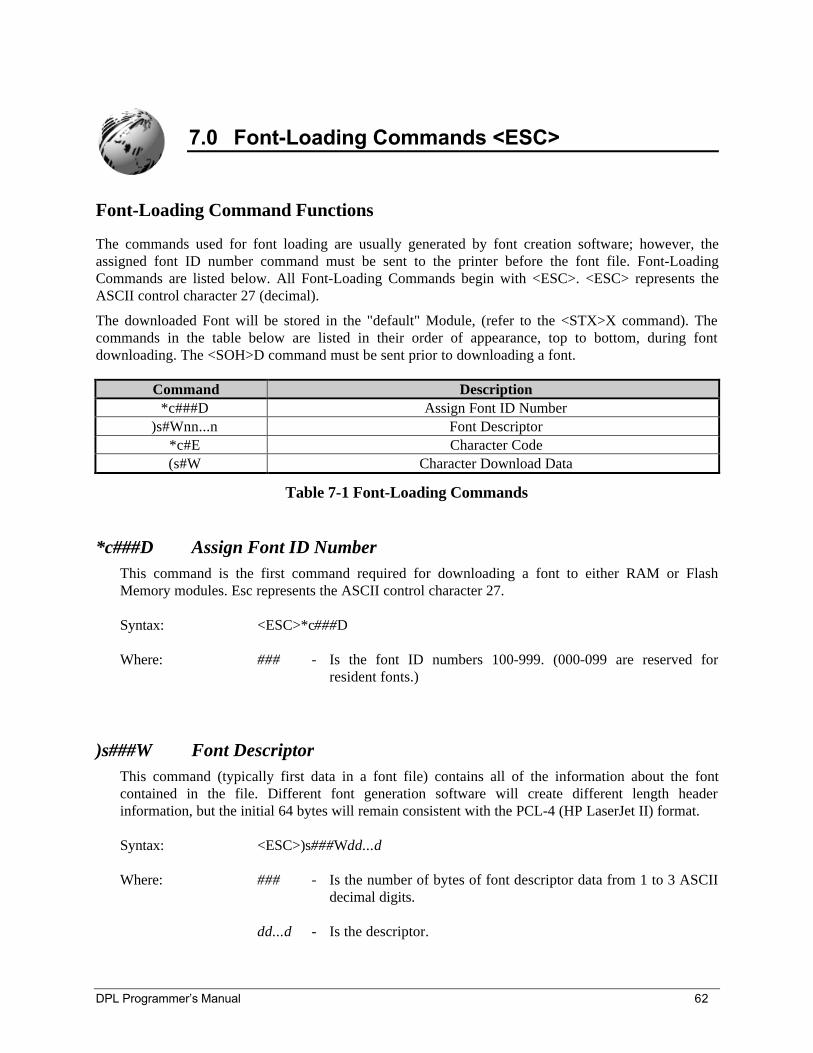
DPL Programmer’s Manual 62
7.0 Font-Loading Commands <ESC>
Font-Loading Command Functions
The commands used for font loading are usually generated by font creation software; however, theassigned font ID number command must be sent to the printer before the font file. Font-LoadingCommands are listed below. All Font-Loading Commands begin with <ESC>. <ESC> represents theASCII control character 27 (decimal).
The downloaded Font will be stored in the "default" Module, (refer to the <STX>X command). Thecommands in the table below are listed in their order of appearance, top to bottom, during fontdownloading. The <SOH>D command must be sent prior to downloading a font.
Command Description*c###D Assign Font ID Number
)s#Wnn...n Font Descriptor*c#E Character Code(s#W Character Download Data
Table 7-1 Font-Loading Commands
*c###D Assign Font ID NumberThis command is the first command required for downloading a font to either RAM or FlashMemory modules. Esc represents the ASCII control character 27.
Syntax: <ESC>*c###D
Where: ### - Is the font ID numbers 100-999. (000-099 are reserved forresident fonts.)
)s###W Font DescriptorThis command (typically first data in a font file) contains all of the information about the fontcontained in the file. Different font generation software will create different length headerinformation, but the initial 64 bytes will remain consistent with the PCL-4 (HP LaserJet II) format.
Syntax: <ESC>)s###Wdd...d
Where: ### - Is the number of bytes of font descriptor data from 1 to 3 ASCIIdecimal digits.
dd...d - Is the descriptor.
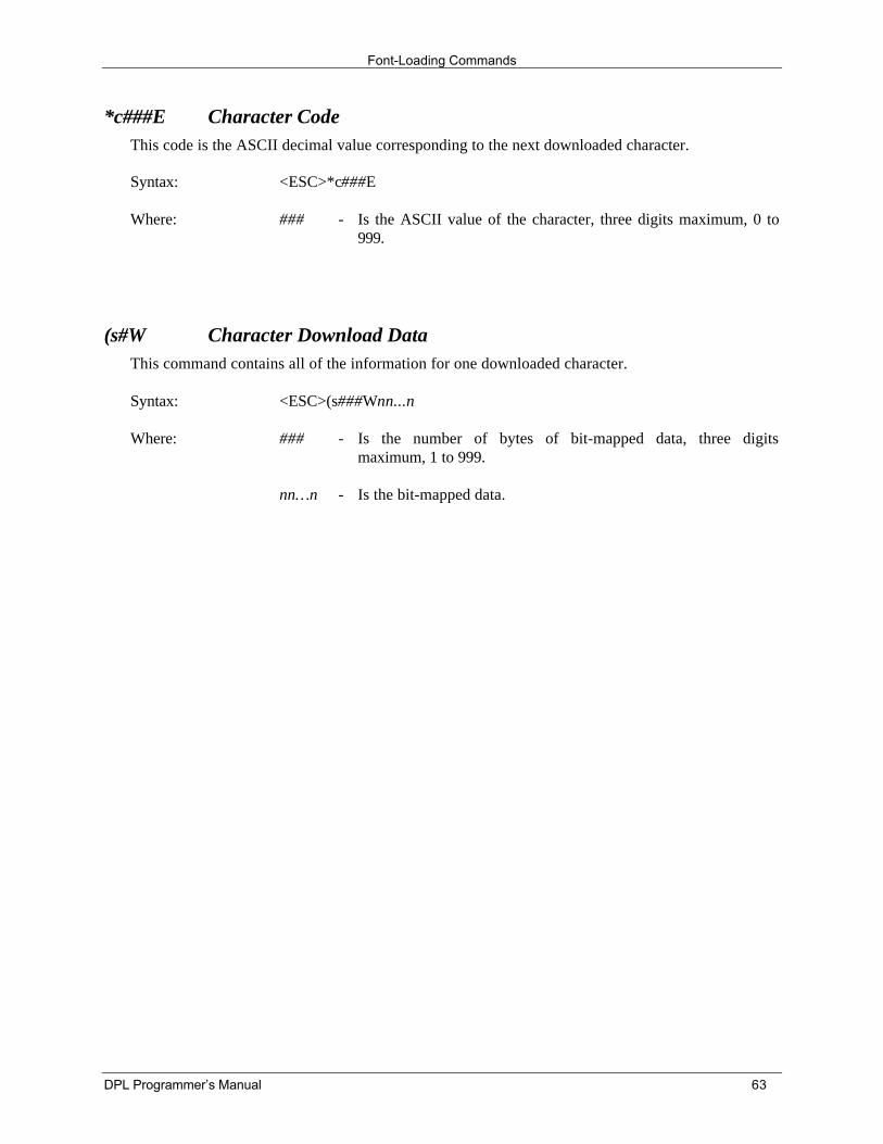
Font-Loading Commands
DPL Programmer’s Manual 63
*c###E Character CodeThis code is the ASCII decimal value corresponding to the next downloaded character.
Syntax: <ESC>*c###E
Where: ### - Is the ASCII value of the character, three digits maximum, 0 to999.
(s#W Character Download DataThis command contains all of the information for one downloaded character.
Syntax: <ESC>(s###Wnn...n
Where: ### - Is the number of bytes of bit-mapped data, three digitsmaximum, 1 to 999.
nn…n - Is the bit-mapped data.
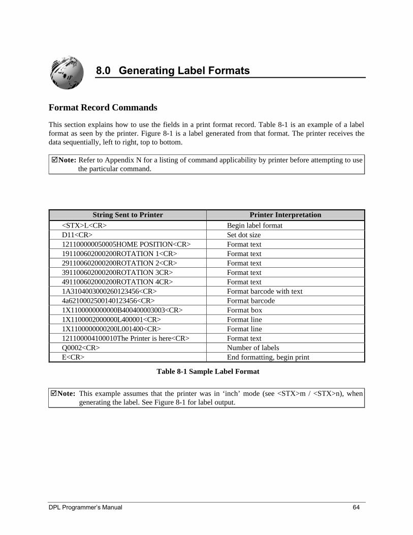
DPL Programmer’s Manual 64
8.0 Generating Label Formats
Format Record Commands
This section explains how to use the fields in a print format record. Table 8-1 is an example of a labelformat as seen by the printer. Figure 8-1 is a label generated from that format. The printer receives thedata sequentially, left to right, top to bottom.
þNote: Refer to Appendix N for a listing of command applicability by printer before attempting to usethe particular command.
String Sent to Printer Printer Interpretation<STX>L<CR> Begin label formatD11<CR> Set dot size121100000050005HOME POSITION<CR> Format text191100602000200ROTATION 1<CR> Format text291100602000200ROTATION 2<CR> Format text391100602000200ROTATION 3CR> Format text491100602000200ROTATION 4CR> Format text1A3104003000260123456<CR> Format barcode with text4a6210002500140123456<CR> Format barcode1X1100000000000B400400003003<CR> Format box1X1100002000000L400001<CR> Format line1X1100000000200L001400<CR> Format line121100004100010The Printer is here<CR> Format textQ0002<CR> Number of labelsE<CR> End formatting, begin print
Table 8-1 Sample Label Format
þNote: This example assumes that the printer was in ‘inch’ mode (see <STX>m / <STX>n), whengenerating the label. See Figure 8-1 for label output.
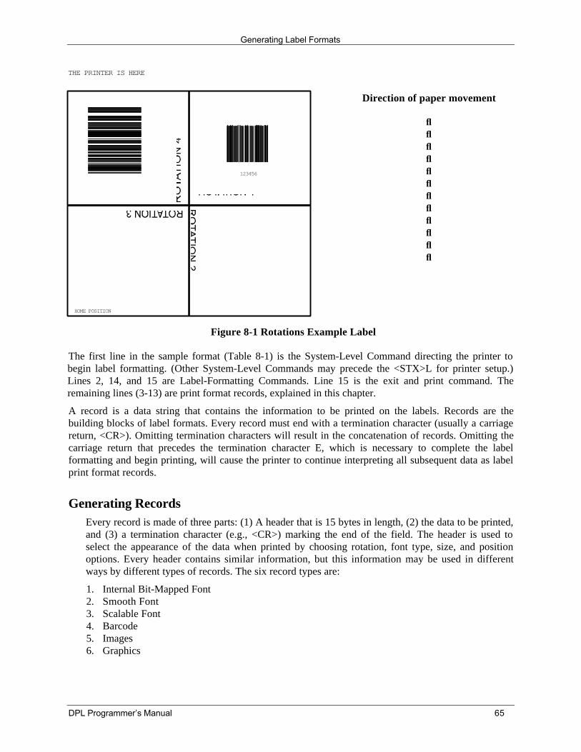
Generating Label Formats
DPL Programmer’s Manual 65
HOME POSITION
THE PRINTER IS HERE
123456
Direction of paper movement
↓↓↓↓↓↓↓↓↓↓↓↓
Figure 8-1 Rotations Example Label
The first line in the sample format (Table 8-1) is the System-Level Command directing the printer tobegin label formatting. (Other System-Level Commands may precede the <STX>L for printer setup.)Lines 2, 14, and 15 are Label-Formatting Commands. Line 15 is the exit and print command. Theremaining lines (3-13) are print format records, explained in this chapter.
A record is a data string that contains the information to be printed on the labels. Records are thebuilding blocks of label formats. Every record must end with a termination character (usually a carriagereturn, <CR>). Omitting termination characters will result in the concatenation of records. Omitting thecarriage return that precedes the termination character E, which is necessary to complete the labelformatting and begin printing, will cause the printer to continue interpreting all subsequent data as labelprint format records.
Generating RecordsEvery record is made of three parts: (1) A header that is 15 bytes in length, (2) the data to be printed,and (3) a termination character (e.g., <CR>) marking the end of the field. The header is used toselect the appearance of the data when printed by choosing rotation, font type, size, and positionoptions. Every header contains similar information, but this information may be used in differentways by different types of records. The six record types are:
1. Internal Bit-Mapped Font2. Smooth Font3. Scalable Font4. Barcode5. Images6. Graphics
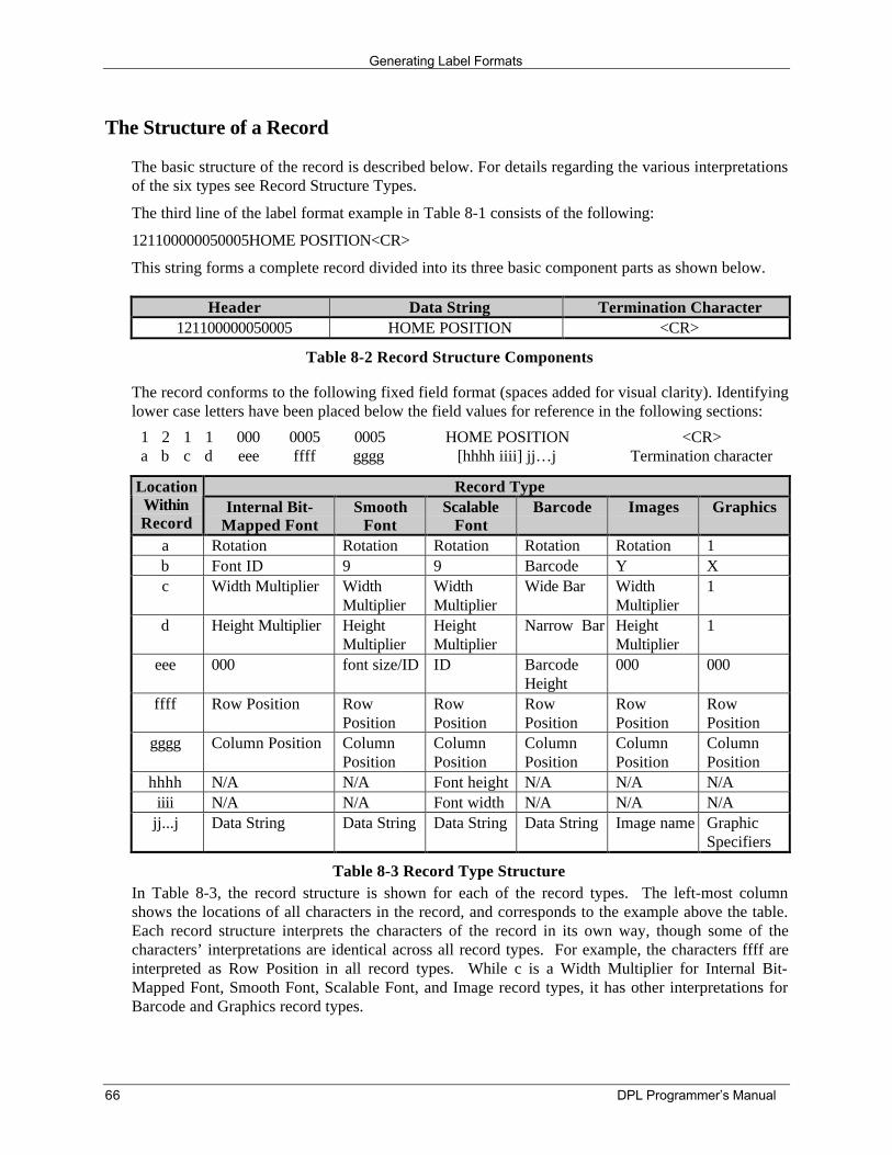
Generating Label Formats
66 DPL Programmer’s Manual
The Structure of a Record
The basic structure of the record is described below. For details regarding the various interpretationsof the six types see Record Structure Types.
The third line of the label format example in Table 8-1 consists of the following:
121100000050005HOME POSITION<CR>
This string forms a complete record divided into its three basic component parts as shown below.
Header Data String Termination Character121100000050005 HOME POSITION <CR>
Table 8-2 Record Structure Components
The record conforms to the following fixed field format (spaces added for visual clarity). Identifyinglower case letters have been placed below the field values for reference in the following sections:
1 2 1 1 000 0005 0005 <CR>a b c d eee ffff gggg
HOME POSITION[hhhh iiii] jj…j Termination character
Record TypeLocationWithinRecord
Internal Bit-Mapped Font
SmoothFont
ScalableFont
Barcode Images Graphics
a Rotation Rotation Rotation Rotation Rotation 1b Font ID 9 9 Barcode Y Xc Width Multiplier Width
MultiplierWidthMultiplier
Wide Bar WidthMultiplier
1
d Height Multiplier HeightMultiplier
HeightMultiplier
Narrow Bar HeightMultiplier
1
eee 000 font size/ID ID BarcodeHeight
000 000
ffff Row Position RowPosition
RowPosition
RowPosition
RowPosition
RowPosition
gggg Column Position ColumnPosition
ColumnPosition
ColumnPosition
ColumnPosition
ColumnPosition
hhhh N/A N/A Font height N/A N/A N/Aiiii N/A N/A Font width N/A N/A N/A
jj...j Data String Data String Data String Data String Image name GraphicSpecifiers
Table 8-3 Record Type StructureIn Table 8-3, the record structure is shown for each of the record types. The left-most columnshows the locations of all characters in the record, and corresponds to the example above the table.Each record structure interprets the characters of the record in its own way, though some of thecharacters’ interpretations are identical across all record types. For example, the characters ffff areinterpreted as Row Position in all record types. While c is a Width Multiplier for Internal Bit-Mapped Font, Smooth Font, Scalable Font, and Image record types, it has other interpretations forBarcode and Graphics record types.
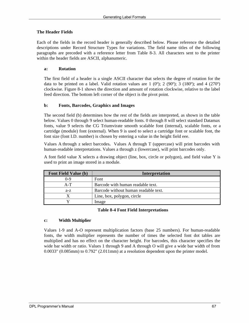
Generating Label Formats
DPL Programmer’s Manual 67
The Header Fields
Each of the fields in the record header is generally described below. Please reference the detaileddescriptions under Record Structure Types for variations. The field name titles of the followingparagraphs are preceded with a reference letter from Table 8-3. All characters sent to the printerwithin the header fields are ASCII, alphanumeric.
a: Rotation
The first field of a header is a single ASCII character that selects the degree of rotation for thedata to be printed on a label. Valid rotation values are 1 (0º); 2 (90º); 3 (180º); and 4 (270º)clockwise. Figure 8-1 shows the direction and amount of rotation clockwise, relative to the labelfeed direction. The bottom left corner of the object is the pivot point.
b: Fonts, Barcodes, Graphics and Images
The second field (b) determines how the rest of the fields are interpreted, as shown in the tablebelow. Values 0 through 9 select human-readable fonts. 0 through 8 will select standard Datamaxfonts, value 9 selects the CG Triumvirate smooth scalable font (internal), scalable fonts, or acartridge (module) font (external). When 9 is used to select a cartridge font or scalable font, thefont size (font I.D. number) is chosen by entering a value in the height field eee.
Values A through z select barcodes. Values A through T (uppercase) will print barcodes withhuman-readable interpretations. Values a through z (lowercase), will print barcodes only.
A font field value X selects a drawing object (line, box, circle or polygon), and field value Y isused to print an image stored in a module.
Font Field Value (b) Interpretation0-9 FontA-T Barcode with human readable text.a-z Barcode without human readable text.X Line, box, polygon, circleY Image
Table 8-4 Font Field Interpretations
c: Width Multiplier
Values 1-9 and A-O represent multiplication factors (base 25 numbers). For human-readablefonts, the width multiplier represents the number of times the selected font dot tables aremultiplied and has no effect on the character height. For barcodes, this character specifies thewide bar width or ratio. Values 1 through 9 and A through O will give a wide bar width of from0.0033" (0.085mm) to 0.792" (2.011mm) at a resolution dependent upon the printer model.
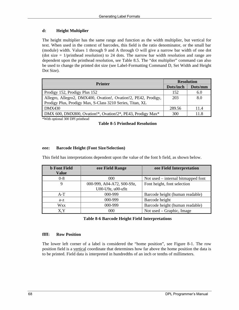
Generating Label Formats
68 DPL Programmer’s Manual
d: Height Multiplier
The height multiplier has the same range and function as the width multiplier, but vertical fortext. When used in the context of barcodes, this field is the ratio denominator, or the small bar(module) width. Values 1 through 9 and A through O will give a narrow bar width of one dot(dot size = 1/printhead resolution) to 24 dots. The narrow bar width resolution and range aredependent upon the printhead resolution, see Table 8.5. The “dot multiplier” command can alsobe used to change the printed dot size (see Label-Formatting Command D, Set Width and HeightDot Size).
ResolutionPrinterDots/inch Dots/mm
Prodigy 152, Prodigy Plus 152 152 6.0Allegro, Allegro2, DMX400, Ovation!, Ovation!2, PE42, Prodigy,Prodigy Plus, Prodigy Max, S-Class 3210 Series, Titan, XL
203 8.0
DMX430 289.56 11.4DMX 600, DMX800, Ovation!*, Ovation!2*, PE43, Prodigy Max* 300 11.8
*With optional 300 DPI printheadTable 8-5 Printhead Resolution
eee: Barcode Height (Font Size/Selection)
This field has interpretations dependent upon the value of the font b field, as shown below.
b Font FieldValue
eee Field Range eee Field Interpretation
0-8 000 Not used – internal bitmapped font9 000-999, A04-A72, S00-S9z,
U00-U9z, u00-u9zFont height, font selection
A-T 000-999 Barcode height (human readable)a-z 000-999 Barcode height
Wxx 000-999 Barcode height (human readable)X,Y 000 Not used – Graphic, Image
Table 8-6 Barcode Height Field Interpretations
ffff: Row Position
The lower left corner of a label is considered the “home position”, see Figure 8-1. The rowposition field is a vertical coordinate that determines how far above the home position the data isto be printed. Field data is interpreted in hundredths of an inch or tenths of millimeters.
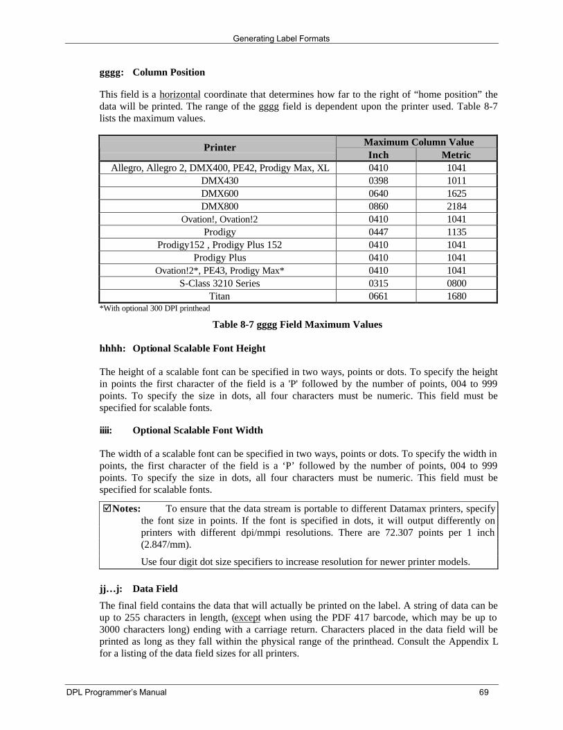
Generating Label Formats
DPL Programmer’s Manual 69
gggg: Column Position
This field is a horizontal coordinate that determines how far to the right of “home position” thedata will be printed. The range of the gggg field is dependent upon the printer used. Table 8-7lists the maximum values.
Maximum Column ValuePrinterInch Metric
Allegro, Allegro 2, DMX400, PE42, Prodigy Max, XL 0410 1041DMX430 0398 1011DMX600 0640 1625DMX800 0860 2184
Ovation!, Ovation!2 0410 1041Prodigy 0447 1135
Prodigy152 , Prodigy Plus 152 0410 1041Prodigy Plus 0410 1041
Ovation!2*, PE43, Prodigy Max* 0410 1041S-Class 3210 Series 0315 0800
Titan 0661 1680*With optional 300 DPI printhead
Table 8-7 gggg Field Maximum Values
hhhh: Optional Scalable Font Height
The height of a scalable font can be specified in two ways, points or dots. To specify the heightin points the first character of the field is a 'P' followed by the number of points, 004 to 999points. To specify the size in dots, all four characters must be numeric. This field must bespecified for scalable fonts.
iiii: Optional Scalable Font Width
The width of a scalable font can be specified in two ways, points or dots. To specify the width inpoints, the first character of the field is a ‘P’ followed by the number of points, 004 to 999points. To specify the size in dots, all four characters must be numeric. This field must bespecified for scalable fonts.
þNotes: To ensure that the data stream is portable to different Datamax printers, specifythe font size in points. If the font is specified in dots, it will output differently onprinters with different dpi/mmpi resolutions. There are 72.307 points per 1 inch(2.847/mm).
Use four digit dot size specifiers to increase resolution for newer printer models.
jj…j: Data Field
The final field contains the data that will actually be printed on the label. A string of data can beup to 255 characters in length, (except when using the PDF 417 barcode, which may be up to3000 characters long) ending with a carriage return. Characters placed in the data field will beprinted as long as they fall within the physical range of the printhead. Consult the Appendix Lfor a listing of the data field sizes for all printers.
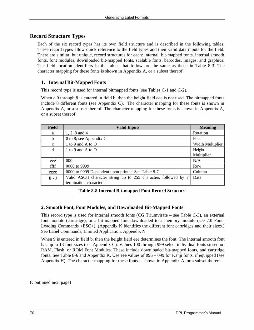
Generating Label Formats
70 DPL Programmer’s Manual
Record Structure TypesEach of the six record types has its own field structure and is described in the following tables.These record types allow quick reference to the field types and their valid data inputs for the field.There are similar, but unique, record structures for each: internal, bit-mapped fonts, internal smoothfonts, font modules, downloaded bit-mapped fonts, scalable fonts, barcodes, images, and graphics.The field location identifiers in the tables that follow are the same as those in Table 8-3. Thecharacter mapping for these fonts is shown in Appendix A, or a subset thereof.
1. Internal Bit-Mapped FontsThis record type is used for internal bitmapped fonts (see Tables C-1 and C-2).
When a 0 through 8 is entered in field b, then the height field eee is not used. The bitmapped fontsinclude 8 different fonts (see Appendix C). The character mapping for these fonts is shown inAppendix A, or a subset thereof. The character mapping for these fonts is shown in Appendix A,or a subset thereof.
Field Valid Inputs Meaninga 1, 2, 3 and 4 Rotationb 0 to 8; see Appendix C. Fontc 1 to 9 and A to O Width Multiplierd 1 to 9 and A to O Height
Multipliereee 000 N/Affff 0000 to 9999 Row
gggg 0000 to 9999 Dependent upon printer. See Table 8-7. Columnjj…j Valid ASCII character string up to 255 characters followed by a
termination character.Data
Table 8-8 Internal Bit-mapped Font Record Structure
2. Smooth Font, Font Modules, and Downloaded Bit-Mapped FontsThis record type is used for internal smooth fonts (CG Triumvirate – see Table C-3), an externalfont module (cartridge), or a bit-mapped font downloaded to a memory module (see 7.0 Font-Loading Commands <ESC>). (Appendix K identifies the different font cartridges and their sizes.)See Label Commands, Limited Application, Appendix N.
When 9 is entered in field b, then the height field eee determines the font. The internal smooth fonthas up to 13 font sizes (see Appendix C). Values 100 through 999 select individual fonts stored onRAM, Flash, or ROM Font Modules. These include downloaded bit-mapped fonts, and cartridgefonts. See Table 8-6 and Appendix K. Use eee values of 096 – 099 for Kanji fonts, if equipped (seeAppendix H). The character mapping for these fonts is shown in Appendix A, or a subset thereof.
(Continued next page)
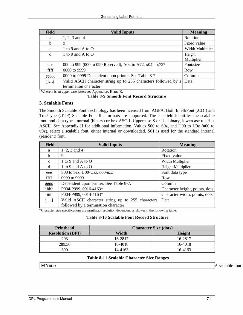
Generating Label Formats
DPL Programmer’s Manual 71
Field Valid Inputs Meaninga 1, 2, 3 and 4 Rotationb 9 Fixed valuec 1 to 9 and A to O Width Multiplierd 1 to 9 and A to O Height
Multipliereee 000 to 999 (000 to 099 Reserved), A04 to A72, x04 – x72* Font/sizeffff 0000 to 9999 Row
gggg 0000 to 9999 Dependent upon printer. See Table 8-7. Columnjj…j Valid ASCII character string up to 255 characters followed by a
termination character.Data
*Where x is an upper case letter; see Appendices H and K.Table 8-9 Smooth Font Record Structure
3. Scalable FontsThe Smooth Scalable Font Technology has been licensed from AGFA. Both IntelliFont (.CDI) andTrueType (.TTF) Scalable Font file formats are supported. The eee field identifies the scalablefont, and data type - normal (binary) or hex ASCII. Uppercase S or U - binary, lowercase u - HexASCII. See Appendix H for additional information. Values S00 to S9z, and U00 to U9z (u00 tou9z), select a scalable font, either internal or downloaded. S01 is used for the standard internal(resident) font.
Field Valid Inputs Meaninga 1, 2, 3 and 4 Rotationb 9 Fixed valuec 1 to 9 and A to O Width Multiplierd 1 to 9 and A to O Height Multiplier
eee S00 to Szz, U00-Uzz, u00-uzz Font data typeffff 0000 to 9999 Row
gggg Dependent upon printer. See Table 8-7. Columnhhhh P004-P999, 0016-4163* Character height, points, dots
iiii P004-P999, 0014-4163* Character width, points, dotsjj…j Valid ASCII character string up to 255 characters
followed by a termination character.Data
*Character size specifications are printhead resolution dependent as shown in the following table.
Table 8-10 Scalable Font Record Structure
Printhead Character Size (dots)Resolution (DPI) Width Height
203 16-2817 16-2817289.56 16-4018 16-4018
300 14-4163 16-4163
Table 8-11 Scalable Character Size Ranges
þNote: A scalable font cache must be allocated to print. Minimum cache size is 15, (see <STX>KS for syntax). Kanji option requires five additional units of cache.
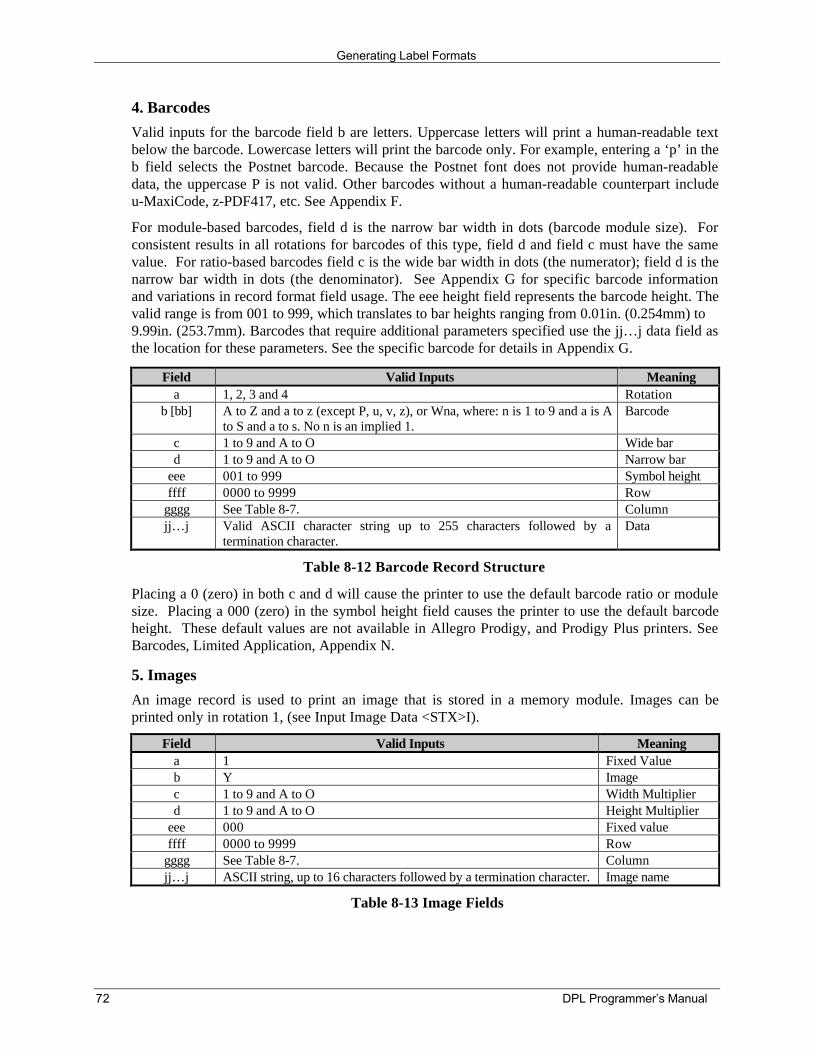
Generating Label Formats
72 DPL Programmer’s Manual
4. BarcodesValid inputs for the barcode field b are letters. Uppercase letters will print a human-readable textbelow the barcode. Lowercase letters will print the barcode only. For example, entering a ‘p’ in theb field selects the Postnet barcode. Because the Postnet font does not provide human-readabledata, the uppercase P is not valid. Other barcodes without a human-readable counterpart includeu-MaxiCode, z-PDF417, etc. See Appendix F.
For module-based barcodes, field d is the narrow bar width in dots (barcode module size). Forconsistent results in all rotations for barcodes of this type, field d and field c must have the samevalue. For ratio-based barcodes field c is the wide bar width in dots (the numerator); field d is thenarrow bar width in dots (the denominator). See Appendix G for specific barcode informationand variations in record format field usage. The eee height field represents the barcode height. Thevalid range is from 001 to 999, which translates to bar heights ranging from 0.01in. (0.254mm) to9.99in. (253.7mm). Barcodes that require additional parameters specified use the jj…j data field asthe location for these parameters. See the specific barcode for details in Appendix G.
Field Valid Inputs Meaninga 1, 2, 3 and 4 Rotation
b [bb] A to Z and a to z (except P, u, v, z), or Wna, where: n is 1 to 9 and a is Ato S and a to s. No n is an implied 1.
Barcode
c 1 to 9 and A to O Wide bard 1 to 9 and A to O Narrow bar
eee 001 to 999 Symbol heightffff 0000 to 9999 Row
gggg See Table 8-7. Columnjj…j Valid ASCII character string up to 255 characters followed by a
termination character.Data
Table 8-12 Barcode Record Structure
Placing a 0 (zero) in both c and d will cause the printer to use the default barcode ratio or modulesize. Placing a 000 (zero) in the symbol height field causes the printer to use the default barcodeheight. These default values are not available in Allegro Prodigy, and Prodigy Plus printers. SeeBarcodes, Limited Application, Appendix N.
5. ImagesAn image record is used to print an image that is stored in a memory module. Images can beprinted only in rotation 1, (see Input Image Data <STX>I).
Field Valid Inputs Meaninga 1 Fixed Valueb Y Imagec 1 to 9 and A to O Width Multiplierd 1 to 9 and A to O Height Multiplier
eee 000 Fixed valueffff 0000 to 9999 Row
gggg See Table 8-7. Columnjj…j ASCII string, up to 16 characters followed by a termination character. Image name
Table 8-13 Image Fields
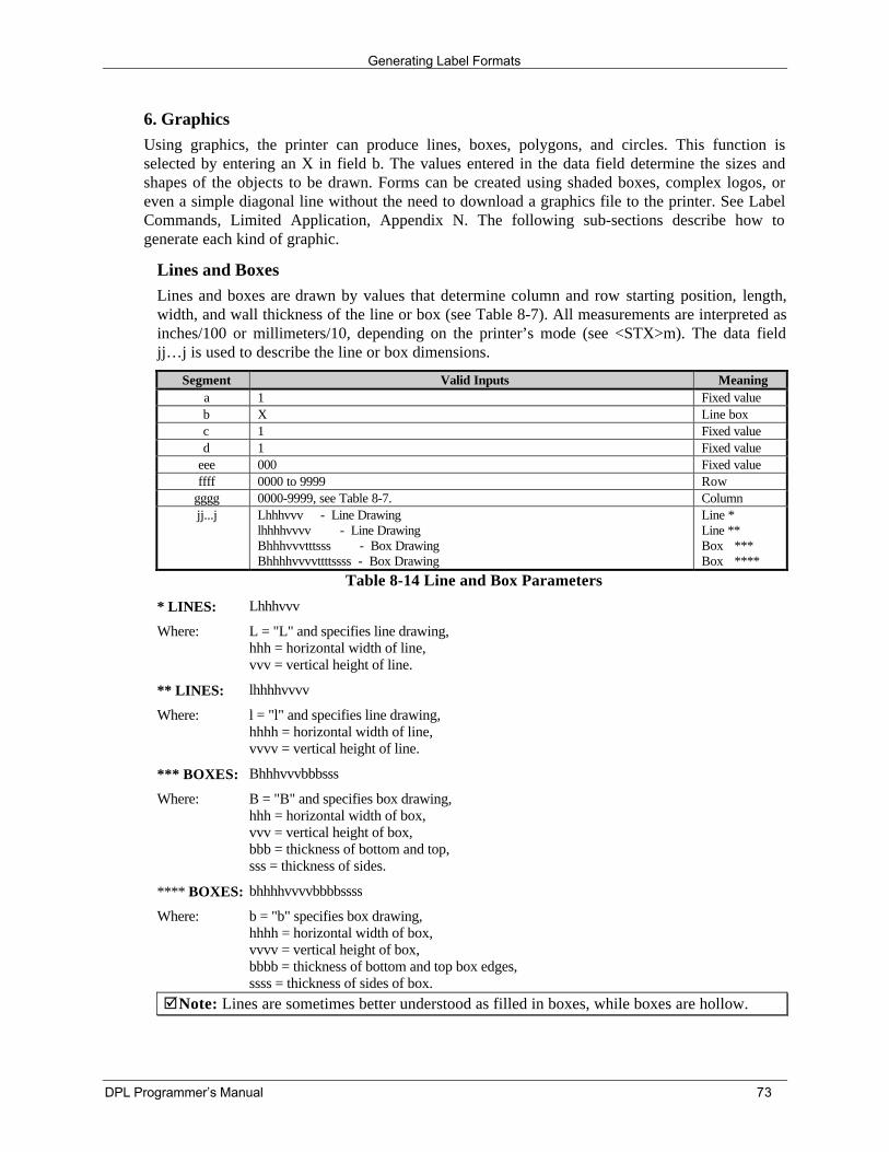
Generating Label Formats
DPL Programmer’s Manual 73
6. GraphicsUsing graphics, the printer can produce lines, boxes, polygons, and circles. This function isselected by entering an X in field b. The values entered in the data field determine the sizes andshapes of the objects to be drawn. Forms can be created using shaded boxes, complex logos, oreven a simple diagonal line without the need to download a graphics file to the printer. See LabelCommands, Limited Application, Appendix N. The following sub-sections describe how togenerate each kind of graphic.
Lines and BoxesLines and boxes are drawn by values that determine column and row starting position, length,width, and wall thickness of the line or box (see Table 8-7). All measurements are interpreted asinches/100 or millimeters/10, depending on the printer’s mode (see <STX>m). The data fieldjj…j is used to describe the line or box dimensions.
Segment Valid Inputs Meaninga 1 Fixed valueb X Line boxc 1 Fixed valued 1 Fixed value
eee 000 Fixed valueffff 0000 to 9999 Row
gggg 0000-9999, see Table 8-7. Columnjj...j Lhhhvvv - Line Drawing
lhhhhvvvv - Line DrawingBhhhvvvtttsss - Box DrawingBhhhhvvvvttttssss - Box Drawing
Line *Line **Box ***Box ****
Table 8-14 Line and Box Parameters
* LINES: Lhhhvvv
Where: L = "L" and specifies line drawing,hhh = horizontal width of line,vvv = vertical height of line.
** LINES: lhhhhvvvv
Where: l = "l" and specifies line drawing,hhhh = horizontal width of line,vvvv = vertical height of line.
*** BOXES: Bhhhvvvbbbsss
Where: B = "B" and specifies box drawing,hhh = horizontal width of box,vvv = vertical height of box,bbb = thickness of bottom and top,sss = thickness of sides.
**** BOXES: bhhhhvvvvbbbbssss
Where: b = "b" specifies box drawing,hhhh = horizontal width of box,vvvv = vertical height of box,bbbb = thickness of bottom and top box edges,ssss = thickness of sides of box.
þNote: Lines are sometimes better understood as filled in boxes, while boxes are hollow.
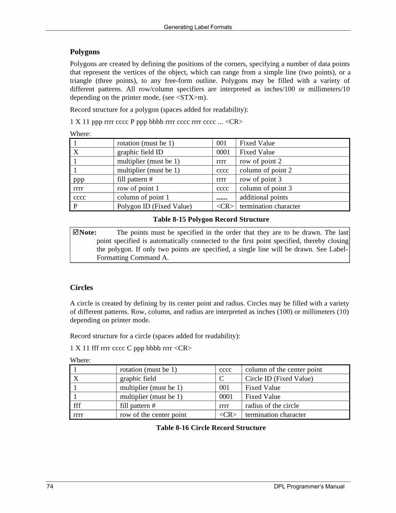
Generating Label Formats
74 DPL Programmer’s Manual
PolygonsPolygons are created by defining the positions of the corners, specifying a number of data pointsthat represent the vertices of the object, which can range from a simple line (two points), or atriangle (three points), to any free-form outline. Polygons may be filled with a variety ofdifferent patterns. All row/column specifiers are interpreted as inches/100 or millimeters/10depending on the printer mode, (see <STX>m).
Record structure for a polygon (spaces added for readability):
1 X 11 ppp rrrr cccc P ppp bbbb rrrr cccc rrrr cccc ... <CR>
Where:1 rotation (must be 1) 001 Fixed ValueX graphic field ID 0001 Fixed Value1 multiplier (must be 1) rrrr row of point 21 multiplier (must be 1) cccc column of point 2ppp fill pattern # rrrr row of point 3rrrr row of point 1 cccc column of point 3cccc column of point 1 ...... additional pointsP Polygon ID (Fixed Value) <CR> termination character
Table 8-15 Polygon Record Structure
þNote: The points must be specified in the order that they are to be drawn. The lastpoint specified is automatically connected to the first point specified, thereby closingthe polygon. If only two points are specified, a single line will be drawn. See Label-Formatting Command A.
Circles
A circle is created by defining by its center point and radius. Circles may be filled with a varietyof different patterns. Row, column, and radius are interpreted as inches (100) or millimeters (10)depending on printer mode.
Record structure for a circle (spaces added for readability):
1 X 11 fff rrrr cccc C ppp bbbb rrrr <CR>
Where:1 rotation (must be 1) cccc column of the center pointX graphic field C Circle ID (Fixed Value)1 multiplier (must be 1) 001 Fixed Value1 multiplier (must be 1) 0001 Fixed Valuefff fill pattern # rrrr radius of the circlerrrr row of the center point <CR> termination character
Table 8-16 Circle Record Structure
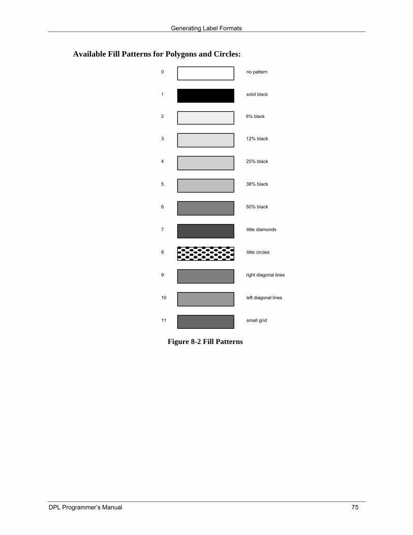
Generating Label Formats
DPL Programmer’s Manual 75
Available Fill Patterns for Polygons and Circles:
0 no pattern
1 solid black
2 6% black
3 12% black
4 25% black
5 38% black
6 50% black
7 little diamonds
8 little circles
9 right diagonal lines
10 left diagonal lines
11 small grid
Figure 8-2 Fill Patterns
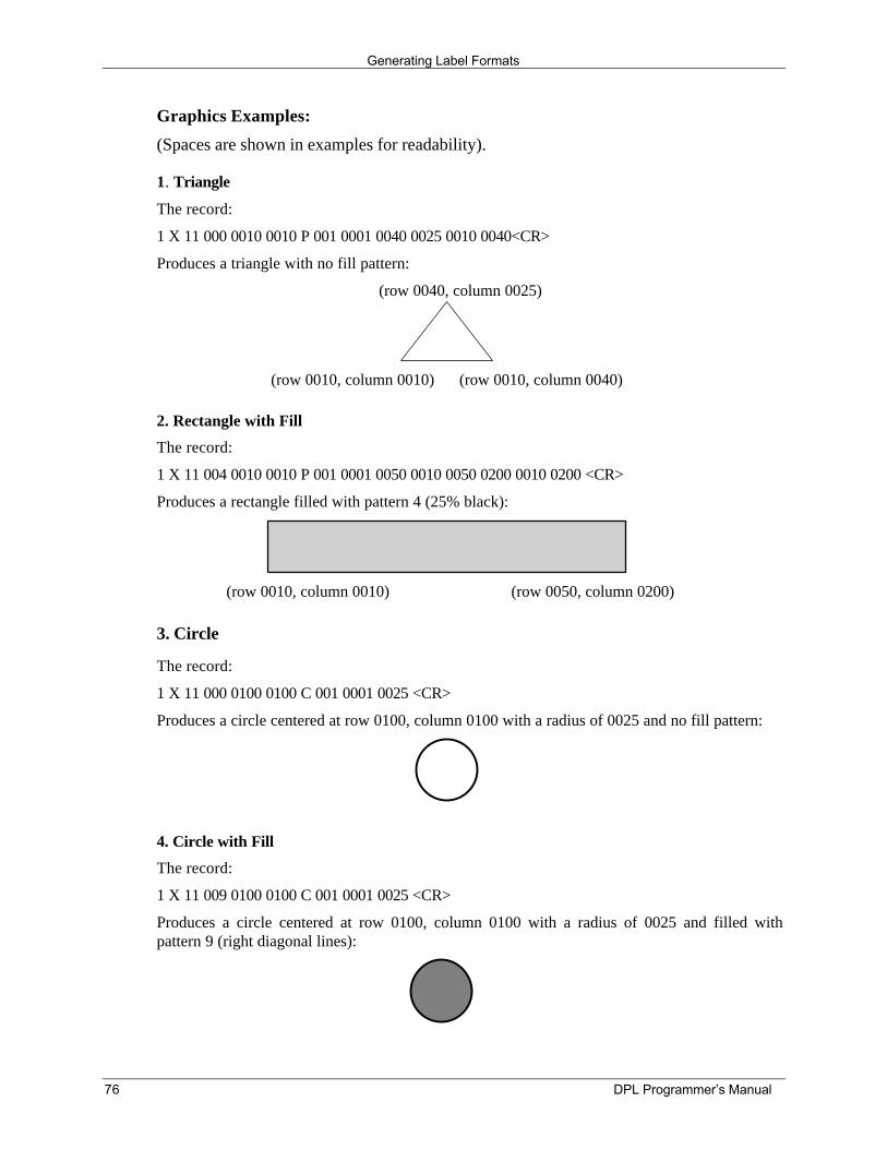
Generating Label Formats
76 DPL Programmer’s Manual
Graphics Examples:
(Spaces are shown in examples for readability).
1. Triangle
The record:
1 X 11 000 0010 0010 P 001 0001 0040 0025 0010 0040<CR>
Produces a triangle with no fill pattern:
(row 0040, column 0025)
(row 0010, column 0010) (row 0010, column 0040)
2. Rectangle with Fill
The record:
1 X 11 004 0010 0010 P 001 0001 0050 0010 0050 0200 0010 0200 <CR>
Produces a rectangle filled with pattern 4 (25% black):
(row 0010, column 0010) (row 0050, column 0200)
3. Circle
The record:
1 X 11 000 0100 0100 C 001 0001 0025 <CR>
Produces a circle centered at row 0100, column 0100 with a radius of 0025 and no fill pattern:
4. Circle with Fill
The record:
1 X 11 009 0100 0100 C 001 0001 0025 <CR>
Produces a circle centered at row 0100, column 0100 with a radius of 0025 and filled withpattern 9 (right diagonal lines):
Generating Label Formats
DPL Programmer’s Manual 77

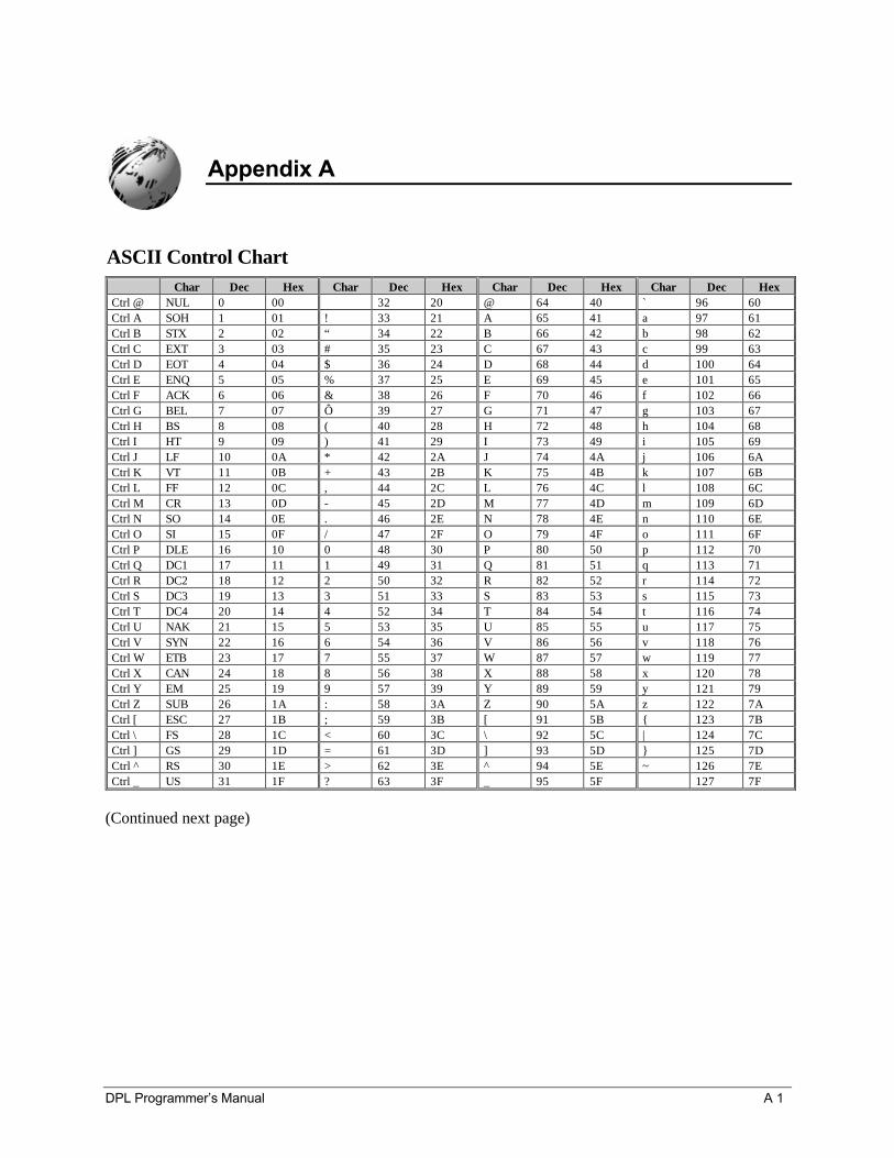
DPL Programmer’s Manual A 1
Appendix A
ASCII Control ChartChar Dec Hex Char Dec Hex Char Dec Hex Char Dec Hex
Ctrl @ NUL 0 00 32 20 @ 64 40 ` 96 60Ctrl A SOH 1 01 ! 33 21 A 65 41 a 97 61Ctrl B STX 2 02 “ 34 22 B 66 42 b 98 62Ctrl C EXT 3 03 # 35 23 C 67 43 c 99 63Ctrl D EOT 4 04 $ 36 24 D 68 44 d 100 64Ctrl E ENQ 5 05 % 37 25 E 69 45 e 101 65Ctrl F ACK 6 06 & 38 26 F 70 46 f 102 66Ctrl G BEL 7 07 Ô 39 27 G 71 47 g 103 67Ctrl H BS 8 08 ( 40 28 H 72 48 h 104 68Ctrl I HT 9 09 ) 41 29 I 73 49 i 105 69Ctrl J LF 10 0A * 42 2A J 74 4A j 106 6ACtrl K VT 11 0B + 43 2B K 75 4B k 107 6BCtrl L FF 12 0C , 44 2C L 76 4C l 108 6CCtrl M CR 13 0D - 45 2D M 77 4D m 109 6DCtrl N SO 14 0E . 46 2E N 78 4E n 110 6ECtrl O SI 15 0F / 47 2F O 79 4F o 111 6FCtrl P DLE 16 10 0 48 30 P 80 50 p 112 70Ctrl Q DC1 17 11 1 49 31 Q 81 51 q 113 71Ctrl R DC2 18 12 2 50 32 R 82 52 r 114 72Ctrl S DC3 19 13 3 51 33 S 83 53 s 115 73Ctrl T DC4 20 14 4 52 34 T 84 54 t 116 74Ctrl U NAK 21 15 5 53 35 U 85 55 u 117 75Ctrl V SYN 22 16 6 54 36 V 86 56 v 118 76Ctrl W ETB 23 17 7 55 37 W 87 57 w 119 77Ctrl X CAN 24 18 8 56 38 X 88 58 x 120 78Ctrl Y EM 25 19 9 57 39 Y 89 59 y 121 79Ctrl Z SUB 26 1A : 58 3A Z 90 5A z 122 7ACtrl [ ESC 27 1B ; 59 3B [ 91 5B 123 7BCtrl \ FS 28 1C < 60 3C \ 92 5C | 124 7CCtrl ] GS 29 1D = 61 3D ] 93 5D 125 7DCtrl ^ RS 30 1E > 62 3E ^ 94 5E ~ 126 7ECtrl _ US 31 1F ? 63 3F _ 95 5F 127 7F
(Continued next page)
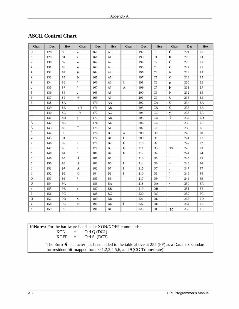
Appendix A
A 2 DPL Programmer’s Manual
ASCII Control Chart
Char Dec Hex Char Dec Hex Char Dec Hex Char Dec Hex
Ç 128 80 á 160 A0 192 C0 Ó 224 E0
ü 129 81 í 161 A1 193 C1 ß 225 E1
é 130 82 ó 162 A2 194 C2 Ô 226 E2
â 131 83 ú 163 A3 195 C3 Ò 227 E3
ä 132 84 ñ 164 A4 196 C4 õ 228 E4
à 133 85 Ñ 165 A5 197 C5 Õ 229 E5
å 134 86 ª 166 A6 ã 198 C6 µ 230 E6
ç 135 87 ° 167 A7 Ã 199 C7 þ 231 E7
ê 136 88 ¿ 168 A8 200 C8 Þ 232 E8
ë 137 89 ® 169 A9 201 C9 Ú 233 E9
è 138 8A 170 AA 202 CA Û 234 EA
ï 139 8B 1/2 171 AB 203 CB Ù 235 EB
î 140 8C 1/4 172 AC 204 CC ý 236 EC
ì 141 8D ¡ 173 AD 205 CD Ý 237 ED
Ä 142 8E 174 AE 206 CE 238 EE
Å 143 8F ¯ 175 AF 207 CF 239 EF
É 144 90 176 B0 ð 208 D0 240 F0
æ 145 91 177 B1 Ð 209 D1 ± 241 F1
Æ 146 92 ² 178 B2 Ê 210 D2 242 F2
ô 147 93 ³ 179 B3 Ë 211 D3 3/4 243 F3
ö 148 94 ´ 180 B4 È 212 D4 244 F4
ò 149 95 Á 181 B5 213 D5 245 F5
û 150 96 Â 182 B6 Í 214 D6 ÷ 246 F6
ù 151 97 À 183 B7 Î 215 D7 ¸ 247 F7
ÿ 152 98 © 184 B8 Ï 216 D8 º 248 F8
Ö 153 99 ¹ 185 B9 217 D9 ¨ 249 F9
Ü 154 9A 186 BA 218 DA · 250 FA
ø 155 9B » 187 BB 219 DB 251 FB
£ 156 9C 188 BC 220 DC 252 FC
Ø 157 9D ¢ 189 BD 221 DD 253 FD
x 158 9E ¥ 190 BE Ì 222 DE 254 FE
ƒ 159 9F 191 BF 223 DF 255 FF
þNotes: For the hardware handshake XON/XOFF commands:XON = Ctrl Q (DC1)XOFF = Ctrl S (DC3)
The Euro character has been added to the table above at 255 (FF) as a Datamax standardfor resident bit-mapped fonts 0,1,2,3,4,5,6, and 9 (CG Triumvirate).
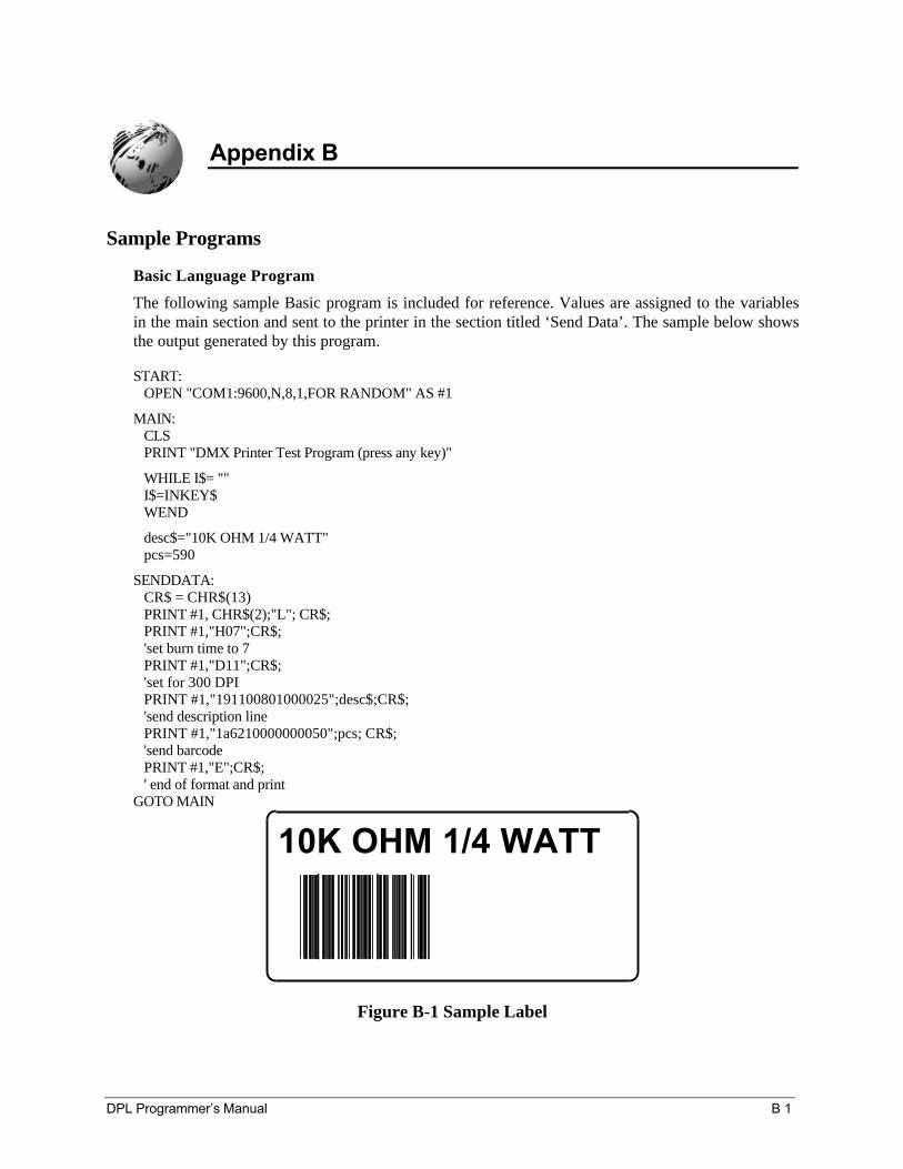
DPL Programmer’s Manual B 1
Appendix B
Sample Programs
Basic Language Program
The following sample Basic program is included for reference. Values are assigned to the variablesin the main section and sent to the printer in the section titled ‘Send Data’. The sample below showsthe output generated by this program.
START: OPEN "COM1:9600,N,8,1,FOR RANDOM" AS #1
MAIN: CLS PRINT "DMX Printer Test Program (press any key)"
WHILE I$= "" I$=INKEY$ WEND
desc$="10K OHM 1/4 WATT" pcs=590
SENDDATA: CR$ = CHR$(13) PRINT #1, CHR$(2);"L"; CR$; PRINT #1,"H07";CR$; 'set burn time to 7 PRINT #1,"D11";CR$; 'set for 300 DPI PRINT #1,"191100801000025";desc$;CR$; 'send description line PRINT #1,"1a6210000000050";pcs; CR$; 'send barcode PRINT #1,"E";CR$; ' end of format and printGOTO MAIN
10K OHM 1/4 WATT
Figure B-1 Sample Label
Appendix B
B 2 DPL Programmer’s Manual
C Language Program
The following C program will also generate the label shown in B-1. This program will send datathrough the COM1 port only.
þNote: With C++ be sure to add the following line: # include <string.h>)
/* DMX SERIES Sample C program.Program written under QuickC. */
# include <stdio.h>
main()
int d;int e;char pcs[10] = "590";char desc[21] = "10K OHM 1/4 WATT";char dataout[500];printf("DMX Printer Test Program\n");strcpy(dataout,"\x02L\x0d");strcat(dataout,"H07\x0d");strcat(dataout,"D11\x0d");strcat(dataout,"191100801000025");strcat(dataout,desc);strcat(dataout,"\x0d");strcat(dataout,"1a6210000000050");strcat(dataout,pcs);strcat(dataout,"PCS\x0d");strcat(dataout,"E\x0d");e = strlen(dataout);for (d=0; d<=e-1; d++)putc(dataout [d],stdaux);
ASCII text file
This ASCII text file will also generate the label shown in Figure B-1.
^BLH07D1119110080100002510K OHM 1/4 WATT<CR>1a6210000000050590PCS<CR>E<CR>
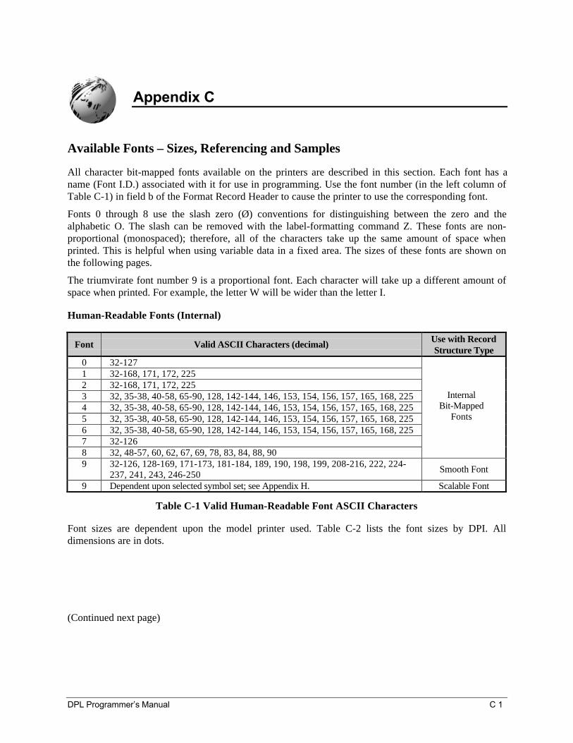
DPL Programmer’s Manual C 1
Appendix C
Available Fonts – Sizes, Referencing and Samples
All character bit-mapped fonts available on the printers are described in this section. Each font has aname (Font I.D.) associated with it for use in programming. Use the font number (in the left column ofTable C-1) in field b of the Format Record Header to cause the printer to use the corresponding font.
Fonts 0 through 8 use the slash zero (Ø) conventions for distinguishing between the zero and thealphabetic O. The slash can be removed with the label-formatting command Z. These fonts are non-proportional (monospaced); therefore, all of the characters take up the same amount of space whenprinted. This is helpful when using variable data in a fixed area. The sizes of these fonts are shown onthe following pages.
The triumvirate font number 9 is a proportional font. Each character will take up a different amount ofspace when printed. For example, the letter W will be wider than the letter I.
Human-Readable Fonts (Internal)
Font Valid ASCII Characters (decimal) Use with RecordStructure Type
0 32-1271 32-168, 171, 172, 2252 32-168, 171, 172, 2253 32, 35-38, 40-58, 65-90, 128, 142-144, 146, 153, 154, 156, 157, 165, 168, 2254 32, 35-38, 40-58, 65-90, 128, 142-144, 146, 153, 154, 156, 157, 165, 168, 2255 32, 35-38, 40-58, 65-90, 128, 142-144, 146, 153, 154, 156, 157, 165, 168, 2256 32, 35-38, 40-58, 65-90, 128, 142-144, 146, 153, 154, 156, 157, 165, 168, 2257 32-1268 32, 48-57, 60, 62, 67, 69, 78, 83, 84, 88, 90
InternalBit-Mapped
Fonts
9 32-126, 128-169, 171-173, 181-184, 189, 190, 198, 199, 208-216, 222, 224-237, 241, 243, 246-250 Smooth Font
9 Dependent upon selected symbol set; see Appendix H. Scalable Font
Table C-1 Valid Human-Readable Font ASCII Characters
Font sizes are dependent upon the model printer used. Table C-2 lists the font sizes by DPI. Alldimensions are in dots.
(Continued next page)
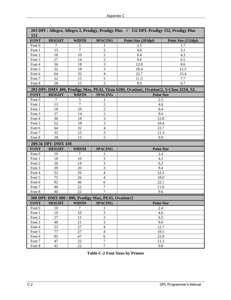
Appendix C
C 2 DPL Programmer’s Manual
203 DPI : Allegro, Allegro 2, Prodigy, Prodigy Plus // 152 DPI: Prodigy 152, Prodigy Plus152FONT HEIGHT WIDTH SPACING Point Size (203dpi) Point Size (152dpi)Font 0 7 5 1 2.5 1.7Font 1 13 7 2 4.6 3.1Font 2 18 10 2 6.4 4.3Font 3 27 14 2 9.6 6.5Font 4 36 18 3 12.8 8.6Font 5 52 18 3 18.4 12.5Font 6 64 32 4 22.7 15.4Font 7 32 15 5 11.3 7.7Font 8 28 15 5 9.9 6.7
203 DPI: DMX 400, Prodigy Max, PE42, Titan 6200, Ovation!, Ovation!2, S-Class 3210, XLFONT HEIGHT WIDTH SPACING Point SizeFont 0 7 5 1 2.5Font 1 13 7 2 4.6Font 2 18 10 2 6.4Font 3 27 14 2 9.6Font 4 36 18 3 12.8Font 5 52 18 3 18.4Font 6 64 32 4 22.7Font 7 32 15 5 11.3Font 8 28 15 5 9.9
289.56 DPI: DMX 430FONT HEIGHT WIDTH SPACING Point SizeFont 0 10 7 1 2.4Font 1 18 10 3 4.3Font 2 26 14 3 6.2Font 3 39 20 3 9.4Font 4 52 26 4 12.5Font 5 75 26 4 18.0Font 6 92 46 6 22.1Font 7 46 22 7 11.0Font 8 40 22 7 9.6
300 DPI: DMX 600 / 800, Prodigy Max, PE43, Ovation!2FONT HEIGHT WIDTH SPACING Point SizeFont 0 10 7 1 2.4Font 1 19 10 3 4.6Font 2 27 15 3 6.5Font 3 40 21 3 9.6Font 4 53 27 4 12.7Font 5 77 27 4 18.5Font 6 95 47 6 22.8Font 7 47 22 7 11.3Font 8 41 22 7 9.8
Table C-2 Font Sizes by Printer
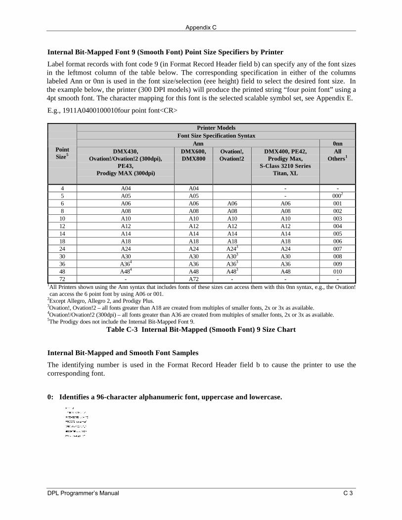
Appendix C
DPL Programmer’s Manual C 3
Internal Bit-Mapped Font 9 (Smooth Font) Point Size Specifiers by Printer
Label format records with font code 9 (in Format Record Header field b) can specify any of the font sizesin the leftmost column of the table below. The corresponding specification in either of the columnslabeled Ann or 0nn is used in the font size/selection (eee height) field to select the desired font size. Inthe example below, the printer (300 DPI models) will produce the printed string “four point font” using a4pt smooth font. The character mapping for this font is the selected scalable symbol set, see Appendix E.
E.g., 1911A0400100010four point font<CR>
Printer ModelsFont Size Specification Syntax
Ann 0nnPointSize5
DMX430,Ovation!/Ovation!2 (300dpi),
PE43,Prodigy MAX (300dpi)
DMX600,DMX800
Ovation!,Ovation!2
DMX400, PE42,Prodigy Max,
S-Class 3210 SeriesTitan, XL
AllOthers1
4 A04 A04 - -5 A05 A05 - 0002
6 A06 A06 A06 A06 0018 A08 A08 A08 A08 002
10 A10 A10 A10 A10 00312 A12 A12 A12 A12 00414 A14 A14 A14 A14 00518 A18 A18 A18 A18 00624 A24 A24 A243 A24 00730 A30 A30 A303 A30 00836 A364 A36 A363 A36 00948 A484 A48 A483 A48 01072 - A72 - - -
1All Printers shown using the Ann syntax that includes fonts of these sizes can access them with this 0nn syntax, e.g., the Ovation!can access the 6 point font by using A06 or 001.
2Except Allegro, Allegro 2, and Prodigy Plus.3Ovation!, Ovation!2 – all fonts greater than A18 are created from multiples of smaller fonts, 2x or 3x as available.4Ovation!/Ovation!2 (300dpi) – all fonts greater than A36 are created from multiples of smaller fonts, 2x or 3x as available.5The Prodigy does not include the Internal Bit-Mapped Font 9.
Table C-3 Internal Bit-Mapped (Smooth Font) 9 Size Chart
Internal Bit-Mapped and Smooth Font Samples
The identifying number is used in the Format Record Header field b to cause the printer to use thecorresponding font.
0: Identifies a 96-character alphanumeric font, uppercase and lowercase.
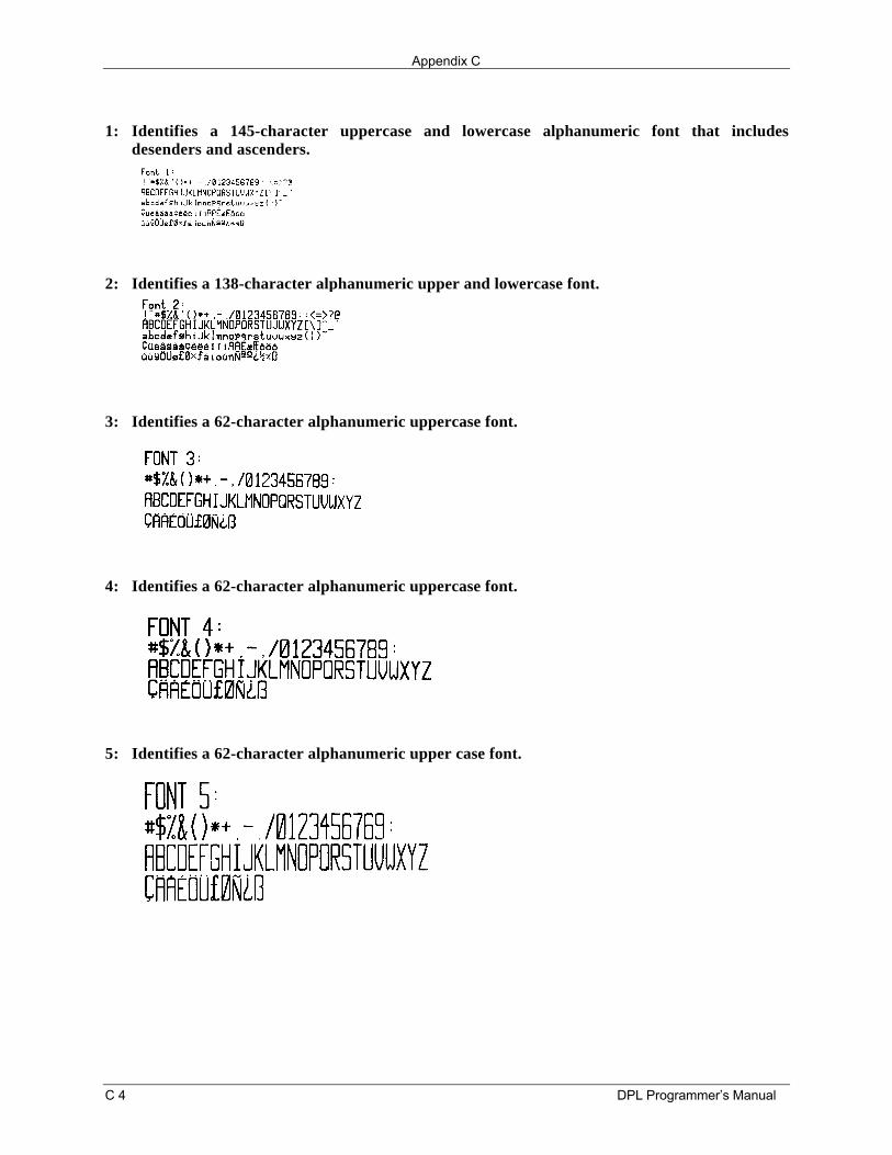
Appendix C
C 4 DPL Programmer’s Manual
1: Identifies a 145-character uppercase and lowercase alphanumeric font that includesdesenders and ascenders.
2: Identifies a 138-character alphanumeric upper and lowercase font.
3: Identifies a 62-character alphanumeric uppercase font.
4: Identifies a 62-character alphanumeric uppercase font.
5: Identifies a 62-character alphanumeric upper case font.
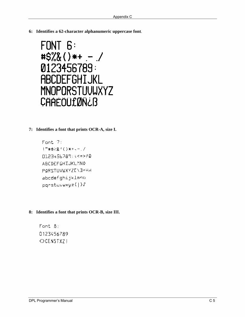
Appendix C
DPL Programmer’s Manual C 5
6: Identifies a 62-character alphanumeric uppercase font.
7: Identifies a font that prints OCR-A, size I.
8: Identifies a font that prints OCR-B, size III.
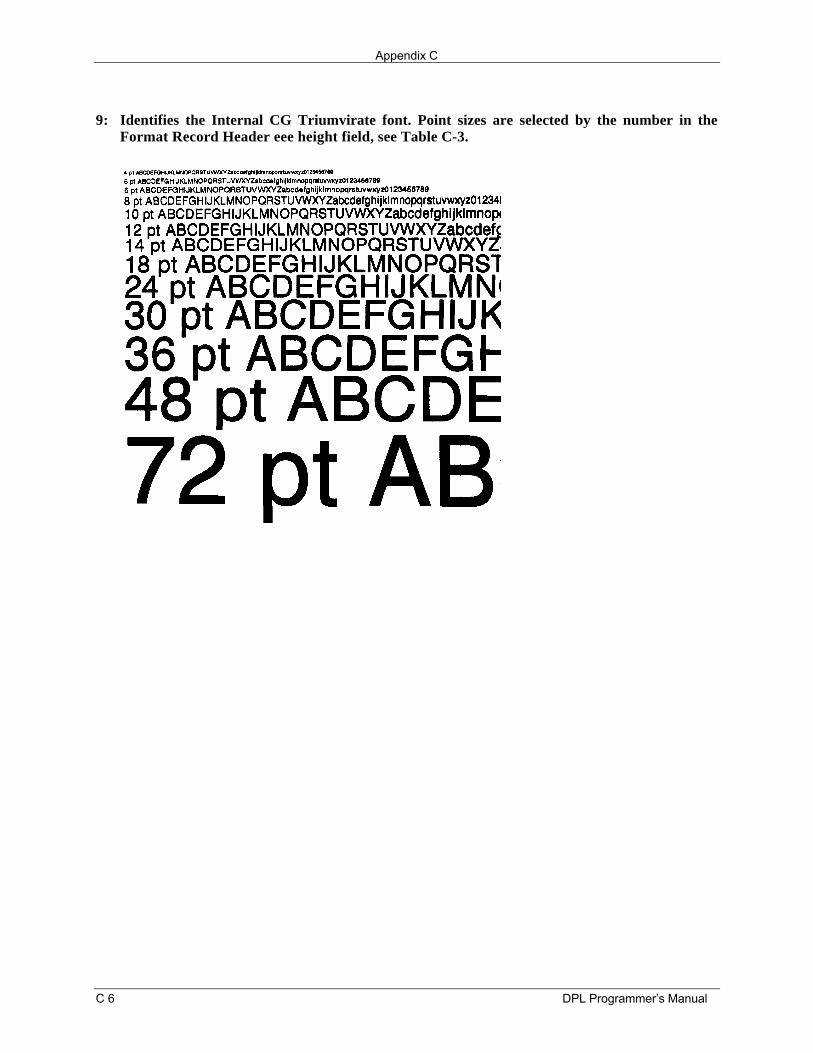
Appendix C
C 6 DPL Programmer’s Manual
9: Identifies the Internal CG Triumvirate font. Point sizes are selected by the number in theFormat Record Header eee height field, see Table C-3.
DPL Programmer’s Manual D 1
Appendix D
Error Codes
The most common error codes that could be transmitted by Datamax printers are described below.
Lowercase "c"
The printer received a data byte from the host computer that contained a framing error (corrupted data -usually due to noise).
Lowercase "v"
There is an input buffer overflow situation; caused when an overflow of data is sent to the printer.
Uppercase "I"
An invalid command sequence was sent to the printer. The printer did not understand the commandsequence and terminated the command interpreter.
Uppercase "R"
This code is sent every time the printer is turned ‘On’, signaling there was a hardware reset.
Uppercase "T"
This code signals there was a software reset. A software reset is made by sending the command sequenceto the printer or by performing a reset using the front panel buttons.
BELL HEX "07"
This code is usually returned on a corrupt image download, or if trying to load an image that alreadyresides in the module.

Appendix D
D 2 DPL Programmer’s Manual
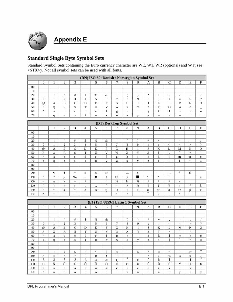
DPL Programmer’s Manual E 1
Appendix E
Standard Single Byte Symbol SetsStandard Symbol Sets containing the Euro currency character are WE, W1, WR (optional) and WT; see<STX>y. Not all symbol sets can be used with all fonts.
(DN) ISO 60: Danish / Norwegian Symbol Set0 1 2 3 4 5 6 7 8 9 A B C D E F
001020 ! " # $ % & ' ( ) * + , . /30 0 1 2 3 4 5 6 7 8 9 : ; < = > ?40 @ A B C D E F G H I J K L M N O50 P Q R S T U V W X Y Z Æ Ø Å ^ _60 ‘ a b c d e f g h i j k l m n o70 p q r s t u v w x y z æ ø å ¯ ±
(DT) DeskTop Symbol Set0 1 2 3 4 5 6 7 8 9 A B C D E F
001020 ! " # $ % & ' ( ) * + , - . /30 0 1 2 3 4 5 6 7 8 9 : ; < = > ?40 @ A B C D E F G H I J K L M N O50 P Q R S T U V W X Y Z [ \ ] ^ -60 ‘ a b c d e f g h i j k l m n o70 p q r s t u v w x y z | ~ ±8090A0 ¶ § † ‡ © ® ¢ – — … fi flB0 “ ” µ ‰ • l o þ n • ? ’ ¬ ¦ =C0 – ± × ÷ ° ′ ″ ¼ ½ ¾ ¹ ² ³ /D0 ( ) « » ‚ „ ’ ¡ ¿ Pt l £ ¥ ¤ ƒ ßE0 ª º æ Æ ð Ð ij IJ t t œ Œ ø Ø þ ÞF0 ‘ ’ ˆ ¨ ˜ ” ° · ¯ , ¸ ' l
(E1) ISO 8859/1 Latin 1 Symbol Set0 1 2 3 4 5 6 7 8 9 A B C D E F
001020 ! " # $ % & ' ( ) * + , - . /30 0 1 2 3 4 5 6 7 8 9 : ; < = > ?40 @ A B C D E F G H I J K L M N O50 P Q R S T U V W X Y Z [ \ ] ^ -60 ‘ a b c d e f g h i j k l m n o70 p q r s t u v w x y z | ~ ±8090A0 ¡ ¢ £ ¤ ¥ ¦ § ¨ © ª « ¬ ® ¯B0 ° ± ² ³ ´ µ ¶ · ¸ ¸ ¹ » ¼ ½ ¾ ¿C0 À Á Â Ã Ä Å Æ Ç È É Ê Ë Ì Í Î ÏD0 Ð Ñ Ò Ó Ô Õ Ö × Ø Ù Ú Û Ü Ý Þ ßE0 à á â ã ä å æ ç è é ê ë ì í î ïF0 ð ñ ò ó ô õ ö ÷ ø ù ú û ü ý þ ÿ
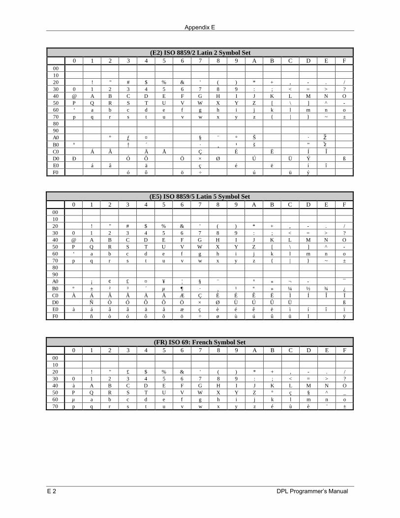
Appendix E
E 2 DPL Programmer’s Manual
(E2) ISO 8859/2 Latin 2 Symbol Set0 1 2 3 4 5 6 7 8 9 A B C D E F
001020 ! " # $ % & ' ( ) * + , . /30 0 1 2 3 4 5 6 7 8 9 : ; < = > ?40 @ A B C D E F G H I J K L M N O50 P Q R S T U V W X Y Z [ \ ] ^ -60 ‘ a b c d e f g h i j k l m n o70 p q r s t u v w x y z | ~ ±8090A0 ° ƒ ¤ § ¨ ° Š · ZB0 º † ´ · ¸ ¹ š ” zC0 Á Â Ä Å Ç É Ë Í ÎD0 Ð Ó Ô Ö × Ø Ú Ü Ý ßE0 á â ä ç é ë í îF0 ó ô ö ÷ ú ü ý
(E5) ISO 8859/5 Latin 5 Symbol Set0 1 2 3 4 5 6 7 8 9 A B C D E F
001020 ! " # $ % & ' ( ) * + , . /30 0 1 2 3 4 5 6 7 8 9 : ; < = > ?40 @ A B C D E F G H I J K L M N O50 P Q R S T U V W X Y Z [ \ ] ^ -60 ‘ a b c d e f g h i j k l m n o70 p q r s t u v w x y z | ~ ±8090A0 ¡ ¢ £ ¤ ¥ ¦ § ¨ ª « ¬ ¯B0 º ± ² ³ ´ µ ¶ · ¸ ¹ º » ¼ ½ ¾ ¿C0 À Á Â Ã Ä Å Æ Ç È É Ê Ë Ì Í Î ÏD0 Ñ Ò Ó Ô Õ Ö × Ø Ù Ú Û Ü ßE0 à á â ã ä å æ ç è é ê ë ì í î ïF0 ñ ò ó ô õ ö ÷ ø ù ú û ü I ÿ
(FR) ISO 69: French Symbol Set0 1 2 3 4 5 6 7 8 9 A B C D E F
001020 ! " £ $ % & ' ( ) * + , . /30 0 1 2 3 4 5 6 7 8 9 : ; < = > ?40 à A B C D E F G H I J K L M N O50 P Q R S T U V W X Y Z º ç § ^ _60 µ a b c d e f g h i j k l m n o70 p q r s t u v w x y z é ù è ¨ ±
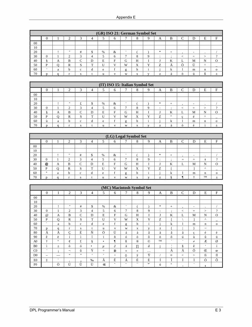
Appendix E
DPL Programmer’s Manual E 3
(GR) ISO 21: German Symbol Set0 1 2 3 4 5 6 7 8 9 A B C D E F
001020 ! " # $ % & ' ( ) * + , . /30 0 1 2 3 4 5 6 7 8 9 : ; < = > ?40 § A B C D E F G H I J K L M N O50 P Q R S T U V W X Y Z Ä Ö Ü ^ _60 ‘ a b c d e f g h i j k l m n o70 p q r s t u v w x y z ä ö ü ß ±
(IT) ISO 15: Italian Symbol Set0 1 2 3 4 5 6 7 8 9 A B C D E F
001020 ! " £ $ % & ' ( ) * + , . /30 0 1 2 3 4 5 6 7 8 9 : ; < = > ?40 § A B C D E F G H I J K L M N O50 P Q R S T U V W X Y Z º ç é ^ _60 ù a b c d e f g h i j k l m n o70 p q r s t u v w x y z à ò è ì ±
(LG) Legal Symbol Set0 1 2 3 4 5 6 7 8 9 A B C D E F
001020 ! " # $ % & ' ( ) * + , - . /30 0 1 2 3 4 5 6 7 8 9 : ; = = ¢ ?40 @ A B C D E F G H I J K L M N O50 P Q R S T U V W X Y Z [ ] ^ _60 ° a b c d e f g h i j k l m n o70 p q r s t u v w x y z § ¶ † ™ ±
(MC) Macintosh Symbol Set0 1 2 3 4 5 6 7 8 9 A B C D E F
001020 ! " # $ % & ' ( ) * + , - . /30 0 1 2 3 4 5 6 7 8 9 : ; < = > ?40 @ A B C D E F G H I J K L M N O50 P Q R S T U V W X Y Z [ \ ] ^ _60 ` a b c d e f g h i j k l m n o70 p q r s t u v w x y z | ~80 Ä Å Ç É Ñ Ö Ü á à â ä ã å ç é è90 ê ë í ì î ï ñ ó ò ô ö õ ú ù û üA0 † º ¢ £ § • ¶ ß ® © ™ ´ ¨ ≠ Æ ØB0 ì ± ò ó • µ ∂ ä ∏ ã ∫ ¦ § ê ‘ íC0 ¨ ¡ ¬ û Ÿ ÷ ∆ « » … À Ã Õ Œ œD0 – — “ ” ‘ ’ ÷ ◊ ÿ Ÿ / ¤ < > fi flE0 ‡ ` ‚ „ ‰ Â Ê Á Ë È Í Î Ï Ì Ó ÔF0 Ò Ú Û Ù ˆ ˜ ¯ ú º ¸ ¨

Appendix E
E 4 DPL Programmer’s Manual
(PC) PC-8 Code Page 437 Symbol Set0 1 2 3 4 5 6 7 8 9 A B C D E F
00 ♥ ♦ ♣ ♠ l R10 × !! ¶ § × ↑ ↓ → ← ↔ s t20 ! " # $ % & ' ( ) * + , - . /30 0 1 2 3 4 5 6 7 8 9 : ; < = > ?40 @ A B C D E F G H I J K L M N O50 P Q R S T U V W X Y Z [ \ ] ^ _60 ` a b c d e f g h i j k l m n o70 p q r s t u v w x y z | ~80 Ç ü é â ä à å ç ê ë è ï î ì Ä Å90 É æ Æ ô ö ò û ù ÿ Ö Ü ¢ £ ¥ Pt ƒA0 á í ó ú ñ Ñ õ Õ ¿ © ª ½ ¼ ¡ « »B0 ° ± ² ³ ´ µ ¶ · ¸ ¹ º » ¼ ½ ¾ ¿C0 À Á Â Ã Ä Å Æ Ç È É Ê Ë Ì Í Î ÏD0 Ð Ñ Ò Ó Ô Õ Ö × Ø Ù Ú Û Ü Ý Þ ßE0 a ß â ã ä å æ ç è é ê ë ì í î ïF0 ð ñ ò ó ô õ ÷ ÷ ° ù ú û ü ² þ
(PD) PC-8 D/N, Code Page 437N Symbol Set0 1 2 3 4 5 6 7 8 9 A B C D E F
00 ♥ ♦ ♣ ♠ l R10 × !! ¶ § é ê → ← ↔ s t20 ! " # $ % & ' ( ) * + , - . /30 0 1 2 3 4 5 6 7 8 9 : ; < = > ?40 @ A B C D E F G H I J K L M N O50 P Q R S T U V W X Y Z [ \ ] ^ _60 ` a b c d e f g h i j k l m n o70 p q r s t u v w x y z | ~80 Ç ü é â ä à å ç ê ë è ï î ì Ä Å90 É æ Æ ô ö ò û ù ÿ Ö Ü ø £ Ø ×A0 á í ó ú ñ Ñ õ Õ ¿ ã Ã ¡ ³ ¤B0 ° ± ² ³ ´ µ ¶ · ¸ ¹ º » ¼ ½ ¾ ¿C0 À Á Â Ã Ä Å Æ Ç È É Ê Ë Ì Í Î ÏD0 Ð Ñ Ò Ó Ô Õ Ö × Ø Ù Ú n Ü Ý Þ ßE0 a ß â ã ä å æ ç è é ê ë ì í î ïF0 ð ñ ò ó ô õ ÷ ÷ ° ù ú û ü ý Ü ÿ
(PE) PC-852 Latin 2 Symbol Set0 1 2 3 4 5 6 7 8 9 A B C D E F
00 ¤ © ¨ « l R10 !! ¶ § — é ê è ç s t20 ! " # $ % & ' ( ) * + , - . /30 0 1 2 3 4 5 6 7 8 9 : ; < = > ?40 @ A B C D E F G H I J K L M N O50 P Q R S T U V W X Y Z [ \ ] ^ _60 ` a b c d e f g h i j k l m n o70 p q r s t u v w x y z | ~80 Ç ü é â ä ç ë î Ä90 É ô ö Ö Ü ×A0 á í ó ú « »B0 ° ± ² ³ ´ Á Â ¹ º » ¼ ¿C0 À Á Â Ã Ä Å È É Ê Ë Ì Í Î ¤D0 Ð Ë Í Î Ù Ú þ ß
E0 Ó ß Ô Š š Ú ý Ý ´F0 " ¸ § ÷ ° ¨ ´ n
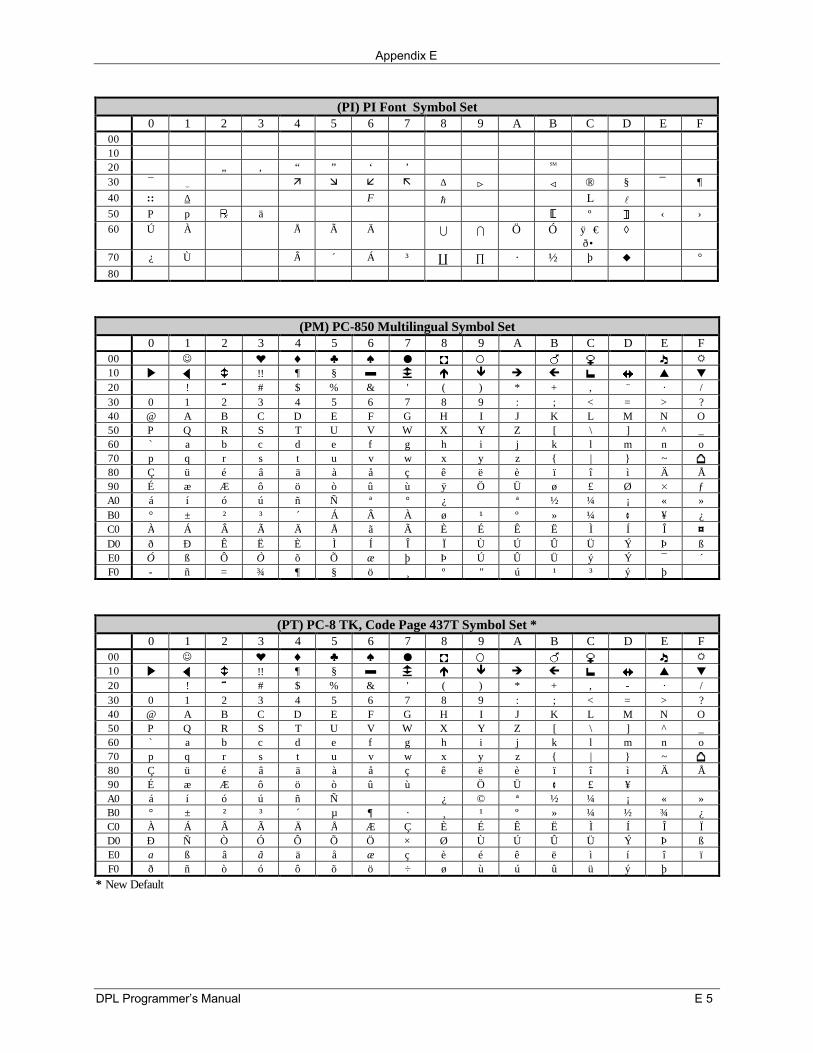
Appendix E
DPL Programmer’s Manual E 5
(PI) PI Font Symbol Set0 1 2 3 4 5 6 7 8 9 A B C D E F
001020 „ ‚ “ ” ‘ ’ ⟨ ⟩ SM 30 ¯ ( ä æ å ã ∆ > ∇ < ® § ¯ ¶40 :: ∆ F h L l50 P p ä º ‹ ›60 Ú À Å Ã Ä U I Ö Ó ÿ €
ð •◊
70 ¿ Ù Â ´ Á ³ C ∏ · ½ þ u °
80
(PM) PC-850 Multilingual Symbol Set0 1 2 3 4 5 6 7 8 9 A B C D E F
00 ¤ © ¨ « l R10 !! ¶ § — é ê è ç s t20 ! ˜ # $ % & ' ( ) * + ‚ ¨ · /30 0 1 2 3 4 5 6 7 8 9 : ; < = > ?40 @ A B C D E F G H I J K L M N O50 P Q R S T U V W X Y Z [ \ ] ^ _60 ` a b c d e f g h i j k l m n o70 p q r s t u v w x y z | ~80 Ç ü é â ä à å ç ê ë è ï î ì Ä Å90 É æ Æ ô ö ò û ù ÿ Ö Ü ø £ Ø × ƒA0 á í ó ú ñ Ñ ª ° ¿ ª ½ ¼ ¡ « »B0 ° ± ² ³ ´ Á Â À ø ¹ º » ¼ ¢ ¥ ¿C0 À Á Â Ã Ä Å ã Ã È É Ê Ë Ì Í Î ¤D0 ð Ð Ê Ë È Ì Í Î Ï Ù Ú Û Ü Ý Þ ßE0 Ó ß Ô Ò õ Õ æ þ Þ Ú Û Ü ý Ý ¯ ´F0 - ñ = ¾ ¶ § ö ¸ º " ú ¹ ³ ý þ
(PT) PC-8 TK, Code Page 437T Symbol Set *0 1 2 3 4 5 6 7 8 9 A B C D E F
00 ¤ © ¨ « l R10 !! ¶ § — é ê è ç s t20 ! ˜ # $ % & ' ( ) * + ‚ - · /30 0 1 2 3 4 5 6 7 8 9 : ; < = > ?40 @ A B C D E F G H I J K L M N O50 P Q R S T U V W X Y Z [ \ ] ^ _60 ` a b c d e f g h i j k l m n o70 p q r s t u v w x y z | ~80 Ç ü é â ä à å ç ê ë è ï î ì Ä Å90 É æ Æ ô ö ò û ù Ö Ü ¢ £ ¥A0 á í ó ú ñ Ñ ¿ © ª ½ ¼ ¡ « »B0 ° ± ² ³ ´ µ ¶ · ¸ ¹ º » ¼ ½ ¾ ¿C0 À Á Â Ã Ä Å Æ Ç È É Ê Ë Ì Í Î ÏD0 Ð Ñ Ò Ó Ô Õ Ö × Ø Ù Ú Û Ü Ý Þ ßE0 a ß â ã ä å æ ç è é ê ë ì í î ïF0 ð ñ ò ó ô õ ö ÷ ø ù ú û ü ý þ
* New Default
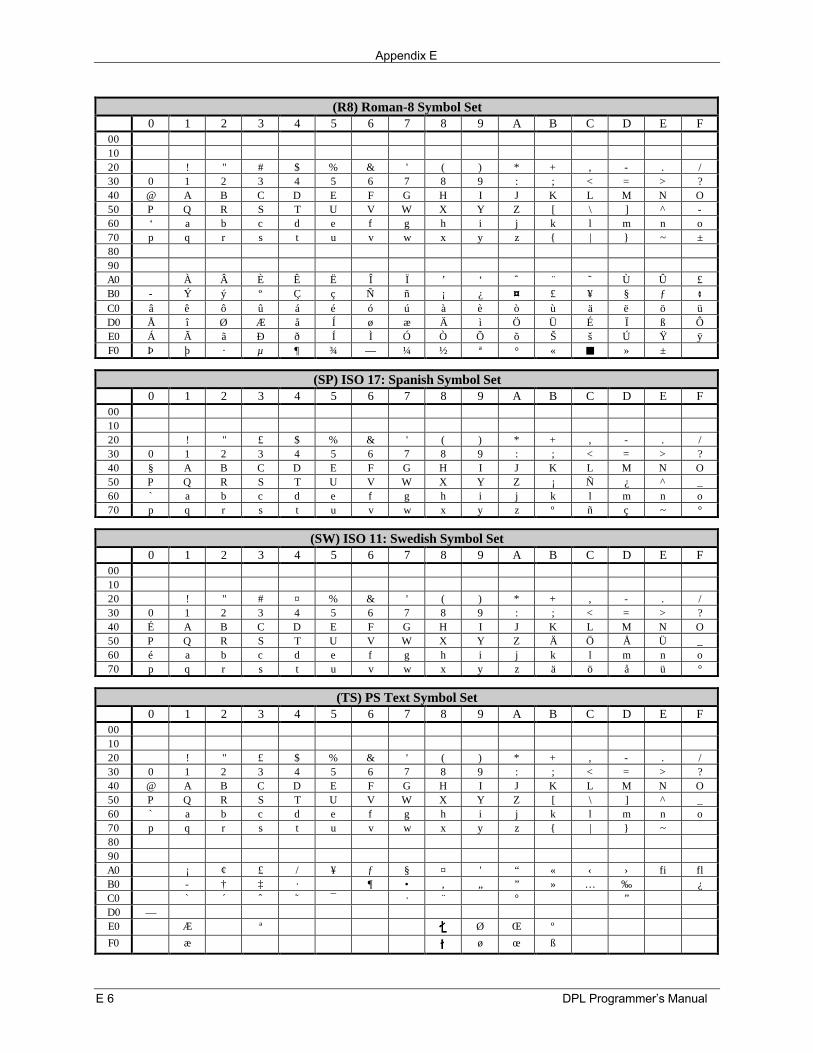
Appendix E
E 6 DPL Programmer’s Manual
(R8) Roman-8 Symbol Set0 1 2 3 4 5 6 7 8 9 A B C D E F
001020 ! " # $ % & ' ( ) * + , - . /30 0 1 2 3 4 5 6 7 8 9 : ; < = > ?40 @ A B C D E F G H I J K L M N O50 P Q R S T U V W X Y Z [ \ ] ^ -60 ‘ a b c d e f g h i j k l m n o70 p q r s t u v w x y z | ~ ±8090A0 À Â È Ê Ë Î Ï ’ ‘ ˆ ¨ ˜ Ù Û £B0 Ý ý º Ç ç Ñ ñ ¡ ¿ ¤ £ ¥ § ƒ ¢C0 â ê ô û á é ó ú à è ò ù ä ë ö üD0 Å î Ø Æ å Í ø æ Ä ì Ö Ü É Ï ß ÔE0 Á Ã ã Ð ð Í Ì Ó Ò Õ õ Š š Ú Ÿ ÿF0 Þ þ · µ ¶ ¾ — ¼ ½ ª ° « n » ±
(SP) ISO 17: Spanish Symbol Set0 1 2 3 4 5 6 7 8 9 A B C D E F
001020 ! " £ $ % & ' ( ) * + , - . /30 0 1 2 3 4 5 6 7 8 9 : ; < = > ?40 § A B C D E F G H I J K L M N O50 P Q R S T U V W X Y Z ¡ Ñ ¿ ^ _60 ` a b c d e f g h i j k l m n o70 p q r s t u v w x y z º ñ ç ~ °
(SW) ISO 11: Swedish Symbol Set0 1 2 3 4 5 6 7 8 9 A B C D E F
001020 ! " # ¤ % & ' ( ) * + , - . /30 0 1 2 3 4 5 6 7 8 9 : ; < = > ?40 É A B C D E F G H I J K L M N O50 P Q R S T U V W X Y Z Ä Ö Å Ü _60 é a b c d e f g h i j k l m n o70 p q r s t u v w x y z ä ö å ü °
(TS) PS Text Symbol Set0 1 2 3 4 5 6 7 8 9 A B C D E F
001020 ! " £ $ % & ' ( ) * + , - . /30 0 1 2 3 4 5 6 7 8 9 : ; < = > ?40 @ A B C D E F G H I J K L M N O50 P Q R S T U V W X Y Z [ \ ] ^ _60 ` a b c d e f g h i j k l m n o70 p q r s t u v w x y z | ~8090A0 ¡ ¢ £ / ¥ ƒ § ¤ ' “ « ‹ › fi flB0 † ‡ · ¶ • , „ ” » … ‰ ¿C0 ` ´ ˆ ˜ ¯ · ¨ ° ”D0 —E0 Æ ª Ø Œ º
F0 æ ø œ ß
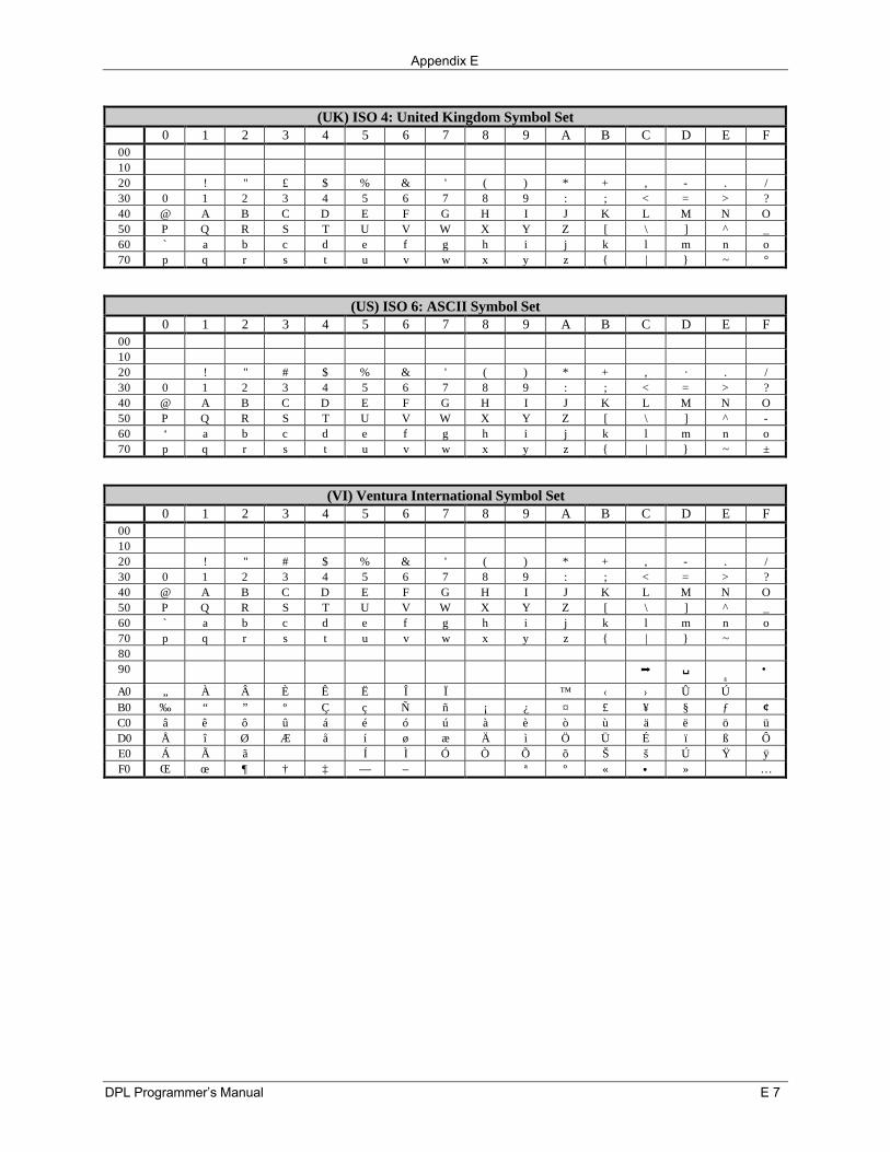
Appendix E
DPL Programmer’s Manual E 7
(UK) ISO 4: United Kingdom Symbol Set0 1 2 3 4 5 6 7 8 9 A B C D E F
001020 ! " £ $ % & ' ( ) * + , - . /30 0 1 2 3 4 5 6 7 8 9 : ; < = > ?40 @ A B C D E F G H I J K L M N O50 P Q R S T U V W X Y Z [ \ ] ^ _60 ` a b c d e f g h i j k l m n o70 p q r s t u v w x y z | ~ °
(US) ISO 6: ASCII Symbol Set0 1 2 3 4 5 6 7 8 9 A B C D E F
001020 ! " # $ % & ' ( ) * + , · . /30 0 1 2 3 4 5 6 7 8 9 : ; < = > ?40 @ A B C D E F G H I J K L M N O50 P Q R S T U V W X Y Z [ \ ] ^ -60 ‘ a b c d e f g h i j k l m n o70 p q r s t u v w x y z | ~ ±
(VI) Ventura International Symbol Set0 1 2 3 4 5 6 7 8 9 A B C D E F
001020 ! " # $ % & ' ( ) * + , - . /30 0 1 2 3 4 5 6 7 8 9 : ; < = > ?40 @ A B C D E F G H I J K L M N O50 P Q R S T U V W X Y Z [ \ ] ^ _60 ` a b c d e f g h i j k l m n o70 p q r s t u v w x y z | ~8090 ↵ Þ
ß•
A0 „ À Â È Ê Ë Î Ï ™ ‹ › Û ÚB0 ‰ “ ” º Ç ç Ñ ñ ¡ ¿ ¤ £ ¥ § ƒ ¢C0 â ê ô û á é ó ú à è ò ù ä ë ö üD0 Å î Ø Æ å í ø æ Ä ì Ö Ü É ï ß ÔE0 Á à ã Í Ì Ó Ò Õ õ Š š Ú Ÿ ÿF0 Œ œ ¶ † ‡ — – ª º « • » …
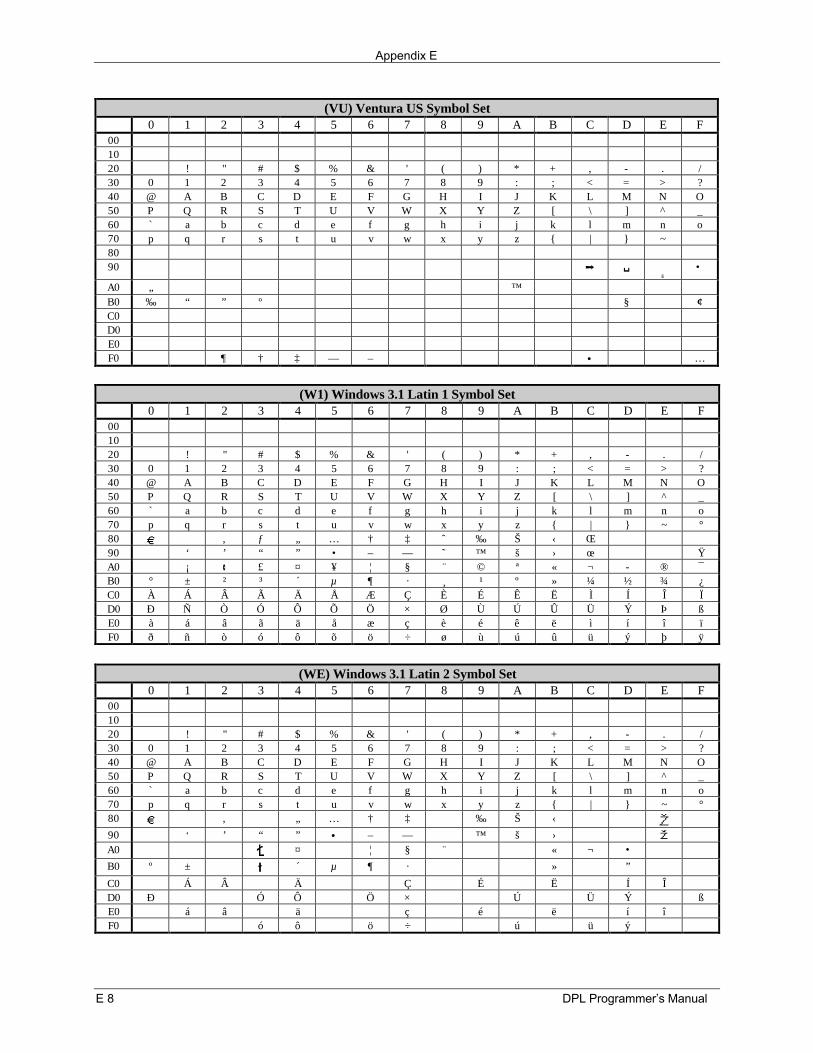
Appendix E
E 8 DPL Programmer’s Manual
(VU) Ventura US Symbol Set0 1 2 3 4 5 6 7 8 9 A B C D E F
001020 ! " # $ % & ' ( ) * + , - . /30 0 1 2 3 4 5 6 7 8 9 : ; < = > ?40 @ A B C D E F G H I J K L M N O50 P Q R S T U V W X Y Z [ \ ] ^ _60 ` a b c d e f g h i j k l m n o70 p q r s t u v w x y z | ~8090 ↵ Þ
ß•
A0 „ ™B0 ‰ “ ” º § ¢C0D0E0F0 ¶ † ‡ — – • …
(W1) Windows 3.1 Latin 1 Symbol Set0 1 2 3 4 5 6 7 8 9 A B C D E F
001020 ! " # $ % & ' ( ) * + , - . /30 0 1 2 3 4 5 6 7 8 9 : ; < = > ?40 @ A B C D E F G H I J K L M N O50 P Q R S T U V W X Y Z [ \ ] ^ _60 ` a b c d e f g h i j k l m n o70 p q r s t u v w x y z | ~ °80 ‚ ƒ „ … † ‡ ˆ ‰ Š ‹ Œ90 ‘ ’ “ ” • – — ˜ ™ š › œ ŸA0 ¡ ¢ £ ¤ ¥ ¦ § ¨ © ª « ¬ ® ¯B0 ° ± ² ³ ´ µ ¶ · ¸ ¹ º » ¼ ½ ¾ ¿C0 À Á Â Ã Ä Å Æ Ç È É Ê Ë Ì Í Î ÏD0 Ð Ñ Ò Ó Ô Õ Ö × Ø Ù Ú Û Ü Ý Þ ßE0 à á â ã ä å æ ç è é ê ë ì í î ïF0 ð ñ ò ó ô õ ö ÷ ø ù ú û ü ý þ ÿ
(WE) Windows 3.1 Latin 2 Symbol Set0 1 2 3 4 5 6 7 8 9 A B C D E F
001020 ! " # $ % & ' ( ) * + , - . /30 0 1 2 3 4 5 6 7 8 9 : ; < = > ?40 @ A B C D E F G H I J K L M N O50 P Q R S T U V W X Y Z [ \ ] ^ _60 ` a b c d e f g h i j k l m n o70 p q r s t u v w x y z | ~ °80 ‚ „ … † ‡ ‰ Š ‹
90 ‘ ’ “ ” • – — ™ š ›A0 ¤ ¦ § ¨ « ¬ • B0 º ± ´ µ ¶ · » ”
C0 Á Â Ä Ç É Ë Í ÎD0 Ð Ó Ô Ö × Ú Ü Ý ßE0 á â ä ç é ë í îF0 ó ô ö ÷ ú ü ý
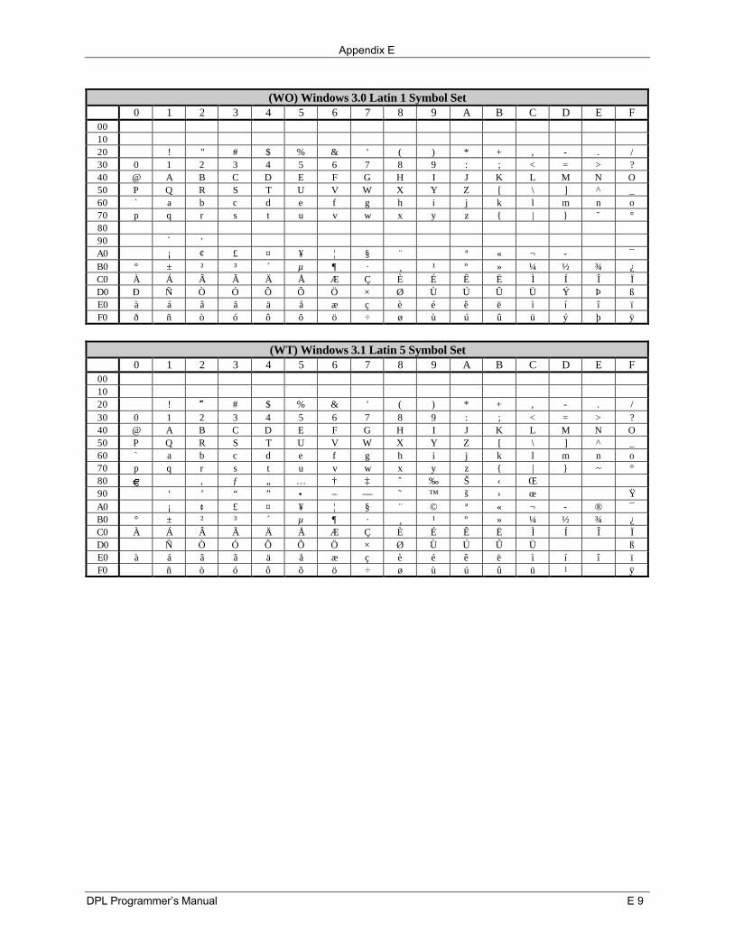
Appendix E
DPL Programmer’s Manual E 9
(WO) Windows 3.0 Latin 1 Symbol Set0 1 2 3 4 5 6 7 8 9 A B C D E F
001020 ! " # $ % & ' ( ) * + , - . /30 0 1 2 3 4 5 6 7 8 9 : ; < = > ?40 @ A B C D E F G H I J K L M N O50 P Q R S T U V W X Y Z [ \ ] ^ _60 ` a b c d e f g h i j k l m n o70 p q r s t u v w x y z | ˜ °8090 ` ’A0 ¡ ¢ £ ¤ ¥ ¦ § ¨ ª « ¬ ¯B0 ° ± ² ³ ´ µ ¶ · ¸ ¹ º » ¼ ½ ¾ ¿C0 À Á Â Ã Ä Å Æ Ç È É Ê Ë Ì Í Î ÏD0 Ð Ñ Ò Ó Ô Õ Ö × Ø Ù Ú Û Ü Ý Þ ßE0 à á â ã ä å æ ç è é ê ë ì í î ïF0 ð ñ ò ó ô õ ö ÷ ø ù ú û ü ý þ ÿ
(WT) Windows 3.1 Latin 5 Symbol Set0 1 2 3 4 5 6 7 8 9 A B C D E F
001020 ! ˜ # $ % & ' ( ) * + ‚ - . /30 0 1 2 3 4 5 6 7 8 9 : ; < = > ?40 @ A B C D E F G H I J K L M N O50 P Q R S T U V W X Y Z [ \ ] ^ _60 ` a b c d e f g h i j k l m n o70 p q r s t u v w x y z | ~ °80 , ƒ „ … † ‡ ˆ ‰ Š ‹ Œ90 ‘ ’ “ ” • – — ˜ ™ š › œ ŸA0 ¡ ¢ £ ¤ ¥ ¦ § ¨ © ª « ¬ ® ¯B0 ° ± ² ³ ´ µ ¶ · ¸ ¹ º » ¼ ½ ¾ ¿C0 À Á Â Ã Ä Å Æ Ç È É Ê Ë Ì Í Î ÏD0 Ñ Ò Ó Ô Õ Ö × Ø Ù Ú Û Ü ßE0 à á â ã ä å æ ç è é ê ë ì í î ïF0 ñ ò ó ô õ ö ÷ ø ù ú û ü l ÿ
Appendix E
E 10 DPL Programmer’s Manual
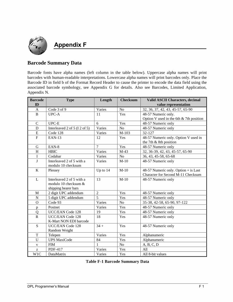
DPL Programmer’s Manual F 1
Appendix F
Barcode Summary Data
Barcode fonts have alpha names (left column in the table below). Uppercase alpha names will printbarcodes with human-readable interpretations. Lowercase alpha names will print barcodes only. Place theBarcode ID in field b of the Format Record Header to cause the printer to encode the data field using theassociated barcode symbology, see Appendix G for details. Also see Barcodes, Limited Application,Appendix N.
BarcodeID
Type Length Checksum Valid ASCII Characters, decimalvalue representation
A Code 3 of 9 Varies No 32, 36, 37, 42, 43, 45-57, 65-90B UPC-A 11 Yes 48-57 Numeric only.
Option V used in the 6th & 7th positionC UPC-E 6 Yes 48-57 Numeric onlyD Interleaved 2 of 5 (I 2 of 5) Varies No 48-57 Numeric onlyE Code 128 Varies M-103 32-127F EAN-13 12 Yes 48-57 Numeric only. Option V used in
the 7th & 8th positionG EAN-8 7 Yes 48-57 Numeric onlyH HBIC Varies M-43 32, 36-39, 42, 43, 45-57, 65-90I Codabar Varies No 36, 43, 45-58, 65-68J Interleaved 2 of 5 with a
modulo 10 checksumVaries M-10 48-57 Numeric only
K Plessey Up to 14 M-10 48-57 Numeric only. Option + is LastCharacter for Second M-11 Checksum
L Interleaved 2 of 5 with amodulo 10 checksum &shipping bearer bars
13 M-10 48-57 Numeric only
M 2 digit UPC addendum 2 Yes 48-57 Numeric onlyN 5 digit UPC addendum 5 Yes 48-57 Numeric onlyO Code 93 Varies No 35-38, 42-58, 65-90, 97-122p Postnet Varies Yes 48-57 Numeric onlyQ UCC/EAN Code 128 19 Yes 48-57 Numeric onlyR UCC/EAN Code 128
K-Mart NON EDI barcode18 Yes 48-57 Numeric only
S UCC/EAN Code 128Random Weight
34 + Yes 48-57 Numeric only
T Telepen Varies Yes AlphanumericU UPS MaxiCode 84 Yes Alphanumericv FIM 1 No A, B, C, Dz PDF-417 Varies Yes All
W1C DataMatrix Varies Yes All 8-bit values
Table F-1 Barcode Summary Data

Appendix F
F 2 DPL Programmer’s Manual
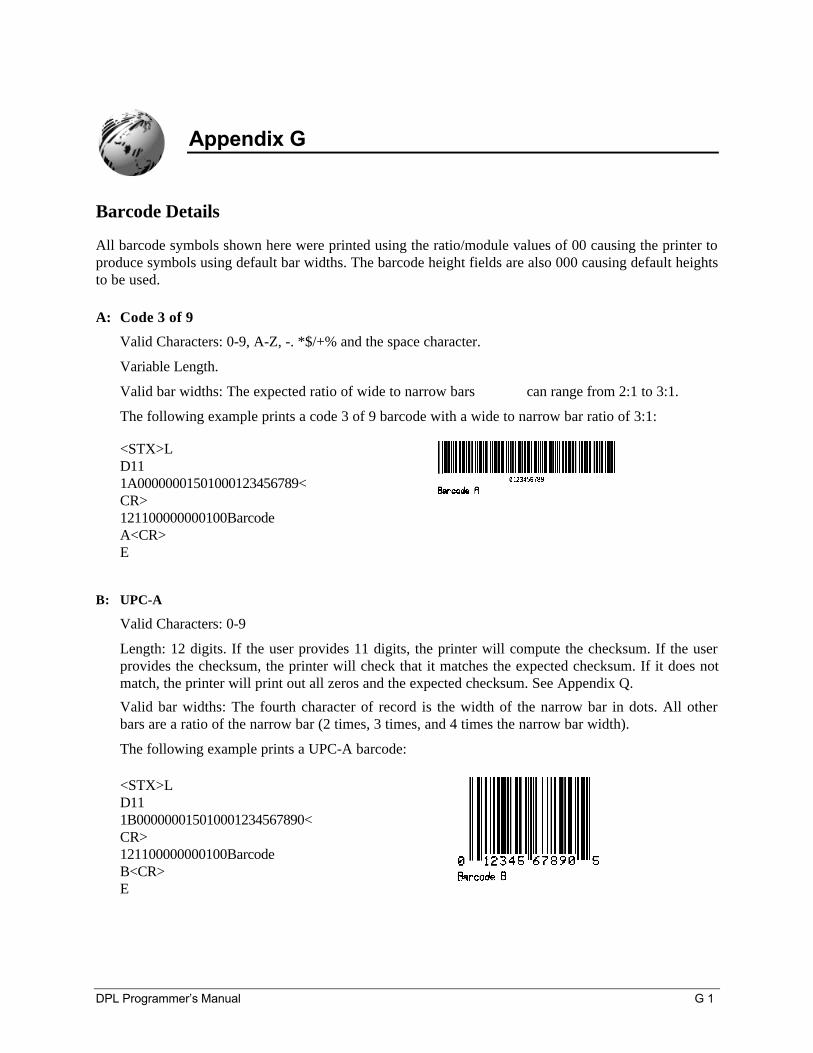
DPL Programmer’s Manual G 1
Appendix G
Barcode Details
All barcode symbols shown here were printed using the ratio/module values of 00 causing the printer toproduce symbols using default bar widths. The barcode height fields are also 000 causing default heightsto be used.
A: Code 3 of 9
Valid Characters: 0-9, A-Z, -. *$/+% and the space character.
Variable Length.
Valid bar widths: The expected ratio of wide to narrow bars can range from 2:1 to 3:1.
The following example prints a code 3 of 9 barcode with a wide to narrow bar ratio of 3:1:
<STX>LD111A00000001501000123456789<CR>121100000000100BarcodeA<CR>E
B: UPC-A
Valid Characters: 0-9
Length: 12 digits. If the user provides 11 digits, the printer will compute the checksum. If the userprovides the checksum, the printer will check that it matches the expected checksum. If it does notmatch, the printer will print out all zeros and the expected checksum. See Appendix Q.
Valid bar widths: The fourth character of record is the width of the narrow bar in dots. All otherbars are a ratio of the narrow bar (2 times, 3 times, and 4 times the narrow bar width).
The following example prints a UPC-A barcode:
<STX>LD111B000000015010001234567890<CR>121100000000100BarcodeB<CR>E
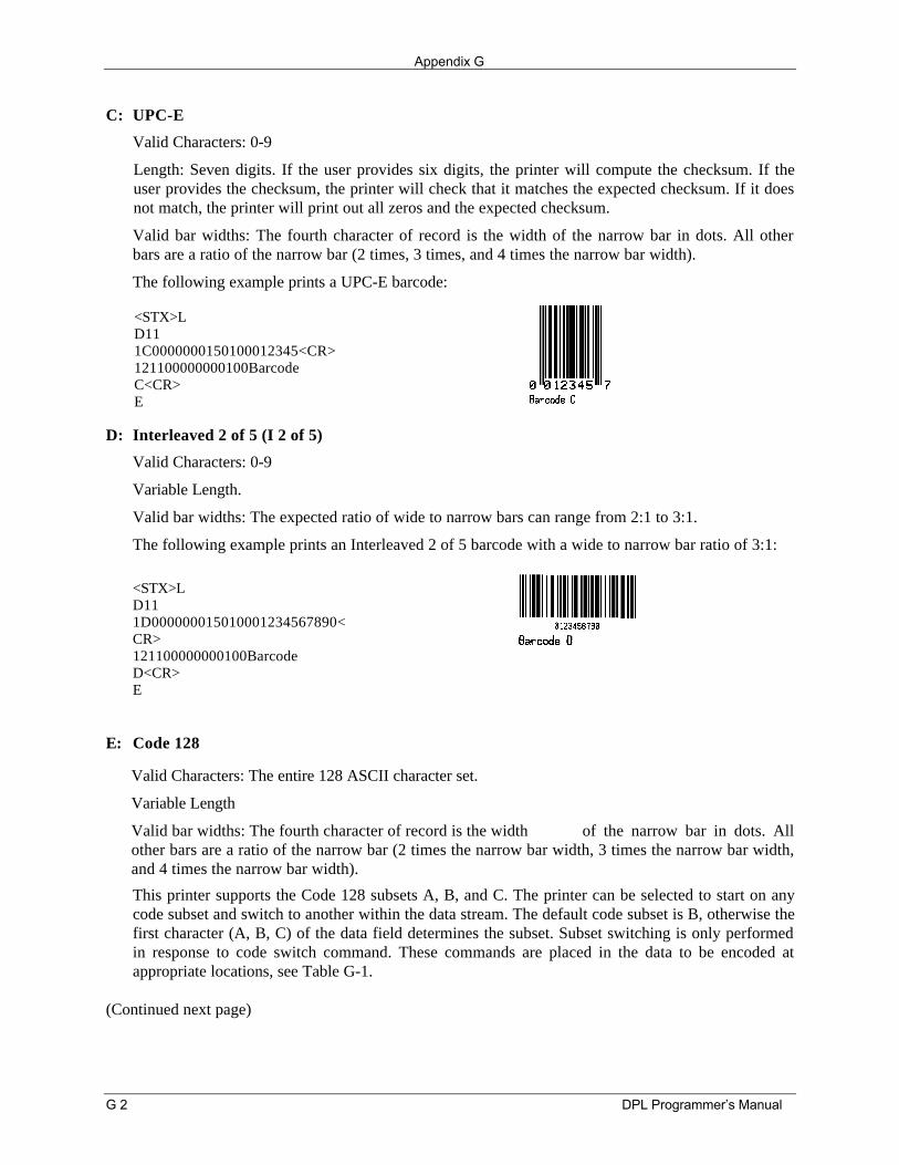
Appendix G
G 2 DPL Programmer’s Manual
C: UPC-E
Valid Characters: 0-9
Length: Seven digits. If the user provides six digits, the printer will compute the checksum. If theuser provides the checksum, the printer will check that it matches the expected checksum. If it doesnot match, the printer will print out all zeros and the expected checksum.
Valid bar widths: The fourth character of record is the width of the narrow bar in dots. All otherbars are a ratio of the narrow bar (2 times, 3 times, and 4 times the narrow bar width).
The following example prints a UPC-E barcode:
<STX>LD111C0000000150100012345<CR>121100000000100BarcodeC<CR>E
D: Interleaved 2 of 5 (I 2 of 5)
Valid Characters: 0-9
Variable Length.
Valid bar widths: The expected ratio of wide to narrow bars can range from 2:1 to 3:1.
The following example prints an Interleaved 2 of 5 barcode with a wide to narrow bar ratio of 3:1:
<STX>LD111D000000015010001234567890<CR>121100000000100BarcodeD<CR>E
E: Code 128
Valid Characters: The entire 128 ASCII character set.
Variable Length
Valid bar widths: The fourth character of record is the width of the narrow bar in dots. Allother bars are a ratio of the narrow bar (2 times the narrow bar width, 3 times the narrow bar width,and 4 times the narrow bar width).
This printer supports the Code 128 subsets A, B, and C. The printer can be selected to start on anycode subset and switch to another within the data stream. The default code subset is B, otherwise thefirst character (A, B, C) of the data field determines the subset. Subset switching is only performedin response to code switch command. These commands are placed in the data to be encoded atappropriate locations, see Table G-1.
(Continued next page)
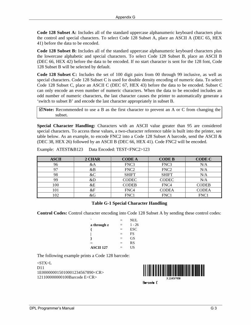
Appendix G
DPL Programmer’s Manual G 3
Code 128 Subset A: Includes all of the standard uppercase alphanumeric keyboard characters plusthe control and special characters. To select Code 128 Subset A, place an ASCII A (DEC 65, HEX41) before the data to be encoded.
Code 128 Subset B: Includes all of the standard uppercase alphanumeric keyboard characters plusthe lowercase alphabetic and special characters. To select Code 128 Subset B, place an ASCII B(DEC 66, HEX 42) before the data to be encoded. If no start character is sent for the 128 font, Code128 Subset B will be selected by default.
Code 128 Subset C: Includes the set of 100 digit pairs from 00 through 99 inclusive, as well asspecial characters. Code 128 Subset C is used for double density encoding of numeric data. To selectCode 128 Subset C, place an ASCII C (DEC 67, HEX 43) before the data to be encoded. Subset Ccan only encode an even number of numeric characters. When the data to be encoded includes anodd number of numeric characters, the last character causes the printer to automatically generate a‘switch to subset B’ and encode the last character appropriately in subset B.
þNote: Recommended to use a B as the first character to prevent an A or C from changing thesubset.
Special Character Handling: Characters with an ASCII value greater than 95 are consideredspecial characters. To access these values, a two-character reference table is built into the printer, seetable below. As an example, to encode FNC2 into a Code 128 Subset A barcode, send the ASCII &(DEC 38, HEX 26) followed by an ASCII B (DEC 66, HEX 41). Code FNC2 will be encoded.
Example: ATEST&B123 Data Encoded: TEST<FNC2>123
ASCII 2 CHAR CODE A CODE B CODE C96 &A FNC3 FNC3 N/A97 &B FNC2 FNC2 N/A98 &C SHIFT SHIFT N/A99 &D CODEC CODEC N/A
100 &E CODEB FNC4 CODEB101 &F FNC4 CODEA CODEA102 &G FNC1 FNC1 FNC1
Table G-1 Special Character Handling
Control Codes: Control character encoding into Code 128 Subset A by sending these control codes:
` = NULa through z = 1 - 26 = ESC| = FS = GS~ = RSASCII 127 = US
The following example prints a Code 128 barcode:
<STX>LD111E000000015010001234567890<CR>121100000000100Barcode E<CR>
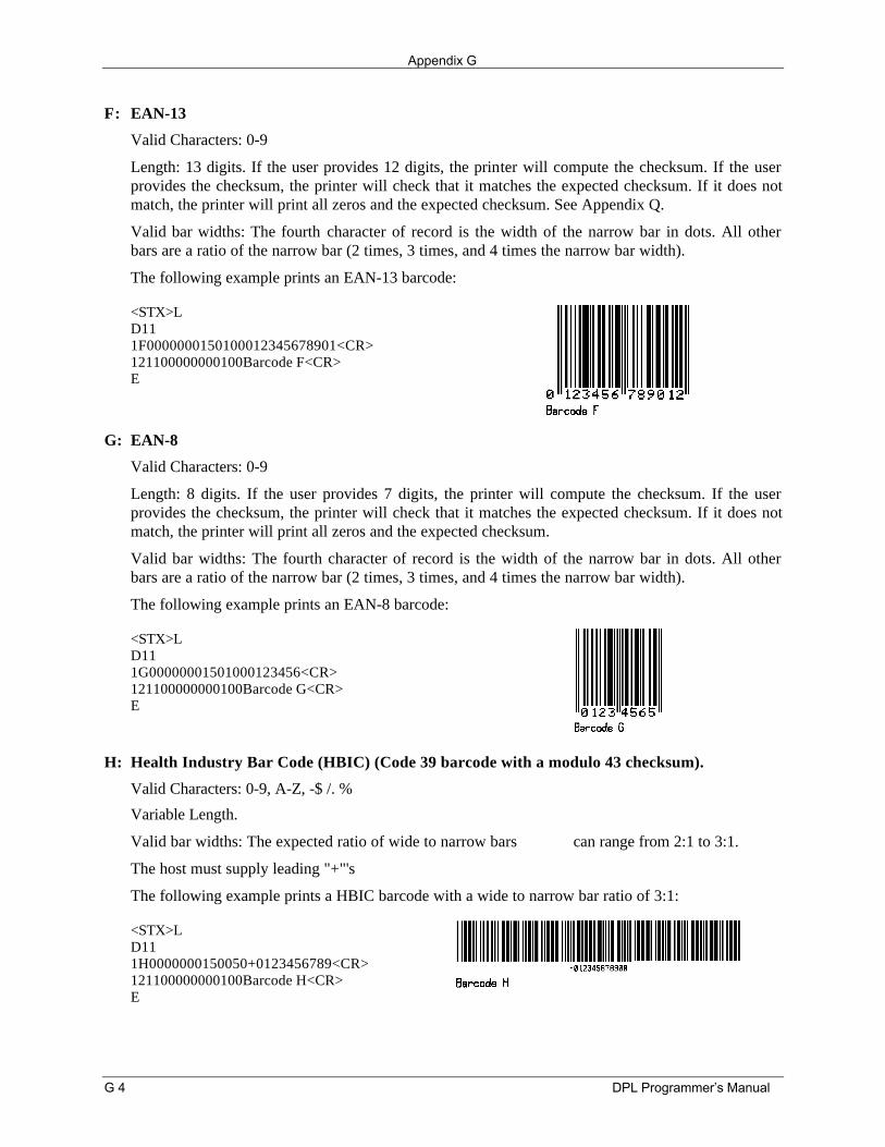
Appendix G
G 4 DPL Programmer’s Manual
F: EAN-13
Valid Characters: 0-9
Length: 13 digits. If the user provides 12 digits, the printer will compute the checksum. If the userprovides the checksum, the printer will check that it matches the expected checksum. If it does notmatch, the printer will print all zeros and the expected checksum. See Appendix Q.
Valid bar widths: The fourth character of record is the width of the narrow bar in dots. All otherbars are a ratio of the narrow bar (2 times, 3 times, and 4 times the narrow bar width).
The following example prints an EAN-13 barcode:
<STX>LD111F0000000150100012345678901<CR>121100000000100Barcode F<CR>E
G: EAN-8
Valid Characters: 0-9
Length: 8 digits. If the user provides 7 digits, the printer will compute the checksum. If the userprovides the checksum, the printer will check that it matches the expected checksum. If it does notmatch, the printer will print all zeros and the expected checksum.
Valid bar widths: The fourth character of record is the width of the narrow bar in dots. All otherbars are a ratio of the narrow bar (2 times, 3 times, and 4 times the narrow bar width).
The following example prints an EAN-8 barcode:
<STX>LD111G00000001501000123456<CR>121100000000100Barcode G<CR>E
H: Health Industry Bar Code (HBIC) (Code 39 barcode with a modulo 43 checksum).
Valid Characters: 0-9, A-Z, -$ /. %
Variable Length.
Valid bar widths: The expected ratio of wide to narrow bars can range from 2:1 to 3:1.
The host must supply leading "+"'s
The following example prints a HBIC barcode with a wide to narrow bar ratio of 3:1:
<STX>LD111H0000000150050+0123456789<CR>121100000000100Barcode H<CR>E
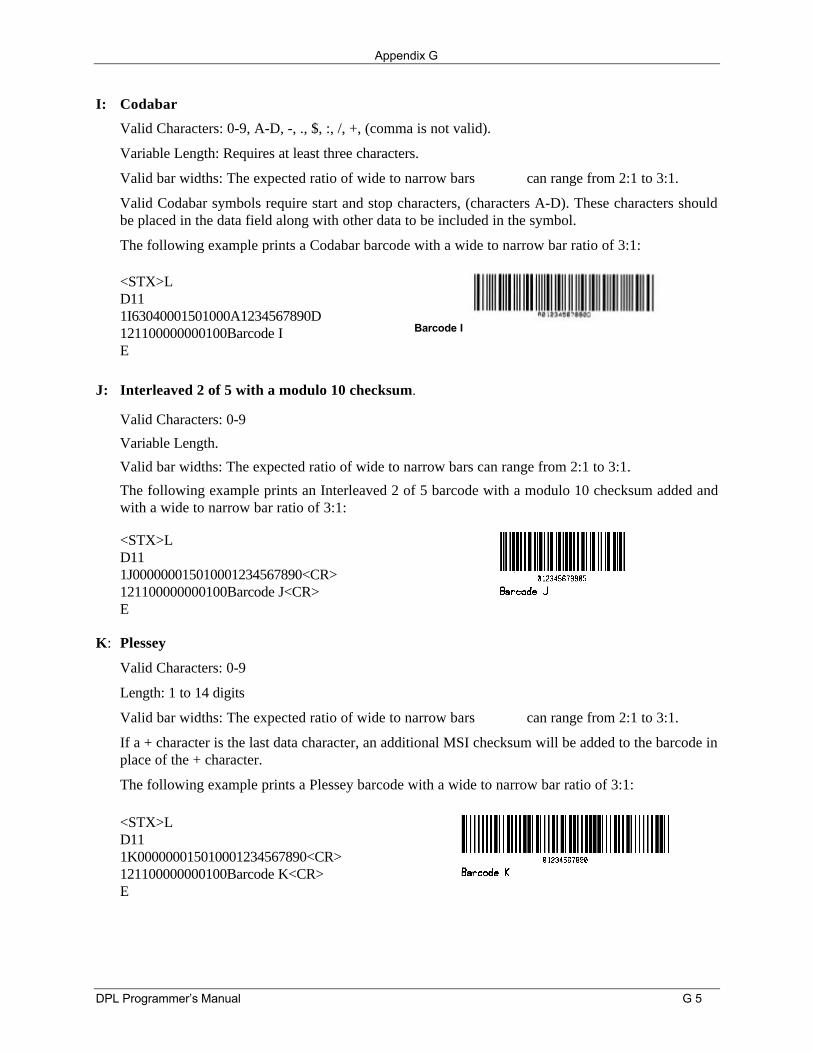
Appendix G
DPL Programmer’s Manual G 5
I: Codabar
Valid Characters: 0-9, A-D, -, ., $, :, /, +, (comma is not valid).
Variable Length: Requires at least three characters.
Valid bar widths: The expected ratio of wide to narrow bars can range from 2:1 to 3:1.
Valid Codabar symbols require start and stop characters, (characters A-D). These characters shouldbe placed in the data field along with other data to be included in the symbol.
The following example prints a Codabar barcode with a wide to narrow bar ratio of 3:1:
<STX>LD111I63040001501000A1234567890D121100000000100Barcode IE
Barcode I
J: Interleaved 2 of 5 with a modulo 10 checksum.
Valid Characters: 0-9
Variable Length.
Valid bar widths: The expected ratio of wide to narrow bars can range from 2:1 to 3:1.
The following example prints an Interleaved 2 of 5 barcode with a modulo 10 checksum added andwith a wide to narrow bar ratio of 3:1:
<STX>LD111J000000015010001234567890<CR>121100000000100Barcode J<CR>E
K: Plessey
Valid Characters: 0-9
Length: 1 to 14 digits
Valid bar widths: The expected ratio of wide to narrow bars can range from 2:1 to 3:1.
If a + character is the last data character, an additional MSI checksum will be added to the barcode inplace of the + character.
The following example prints a Plessey barcode with a wide to narrow bar ratio of 3:1:
<STX>LD111K000000015010001234567890<CR>121100000000100Barcode K<CR>E
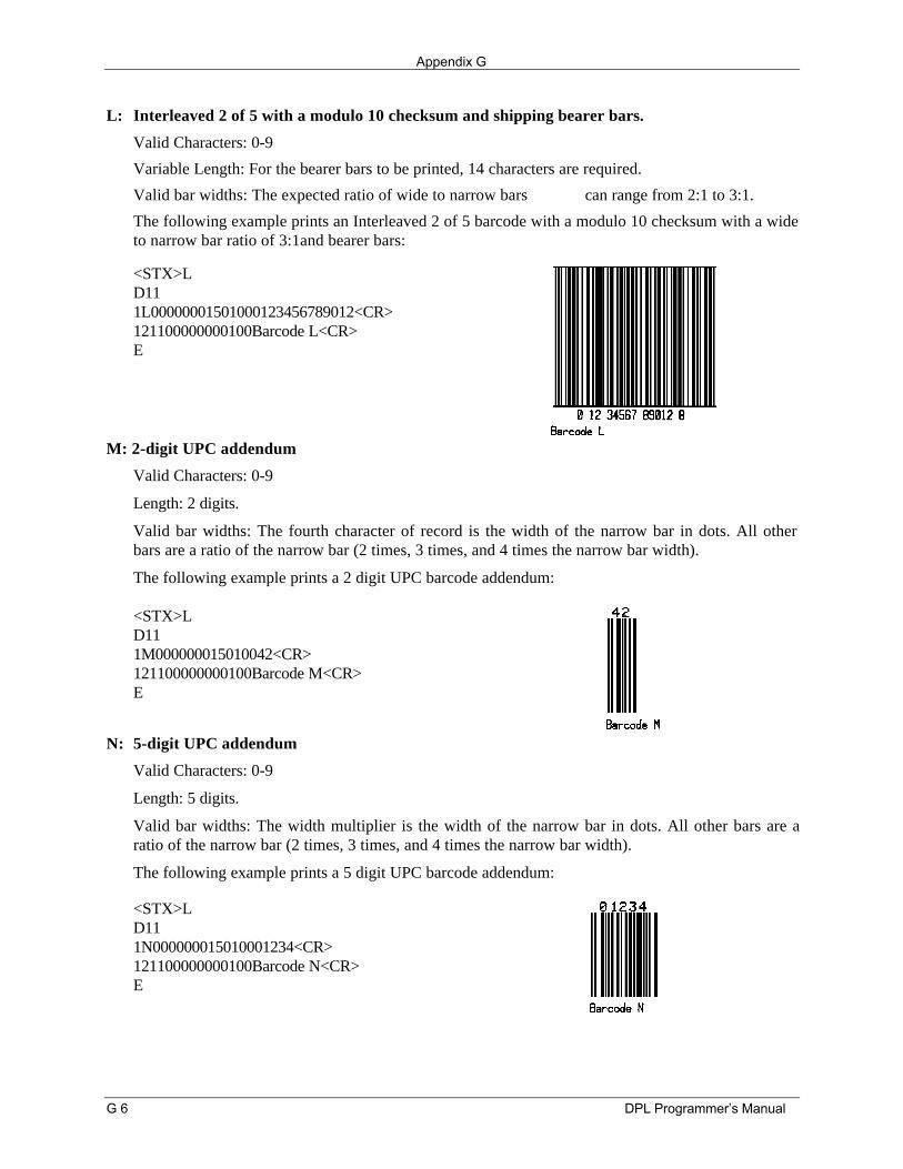
Appendix G
G 6 DPL Programmer’s Manual
L: Interleaved 2 of 5 with a modulo 10 checksum and shipping bearer bars.
Valid Characters: 0-9
Variable Length: For the bearer bars to be printed, 14 characters are required.
Valid bar widths: The expected ratio of wide to narrow bars can range from 2:1 to 3:1.
The following example prints an Interleaved 2 of 5 barcode with a modulo 10 checksum with a wideto narrow bar ratio of 3:1and bearer bars:
<STX>LD111L00000001501000123456789012<CR>121100000000100Barcode L<CR>E
M: 2-digit UPC addendum
Valid Characters: 0-9
Length: 2 digits.
Valid bar widths: The fourth character of record is the width of the narrow bar in dots. All otherbars are a ratio of the narrow bar (2 times, 3 times, and 4 times the narrow bar width).
The following example prints a 2 digit UPC barcode addendum:
<STX>LD111M000000015010042<CR>121100000000100Barcode M<CR>E
N: 5-digit UPC addendum
Valid Characters: 0-9
Length: 5 digits.
Valid bar widths: The width multiplier is the width of the narrow bar in dots. All other bars are aratio of the narrow bar (2 times, 3 times, and 4 times the narrow bar width).
The following example prints a 5 digit UPC barcode addendum:
<STX>LD111N000000015010001234<CR>121100000000100Barcode N<CR>E
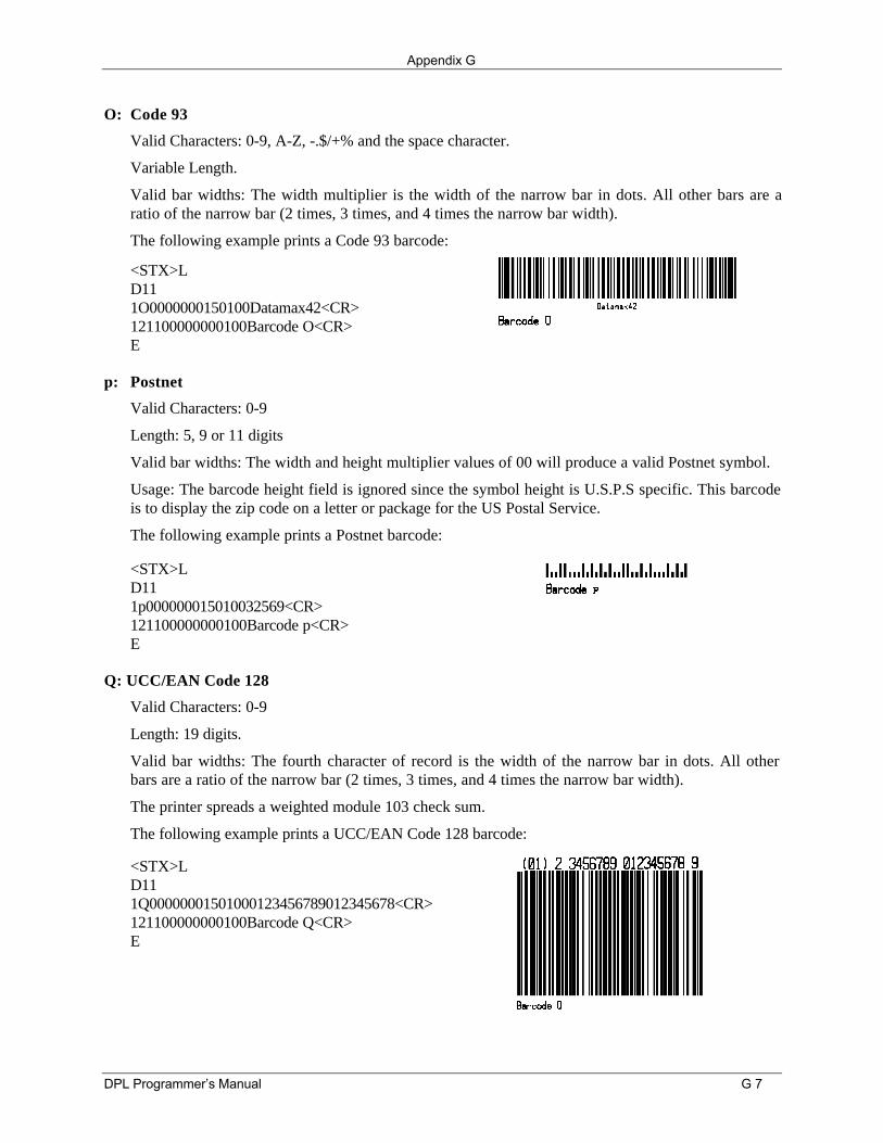
Appendix G
DPL Programmer’s Manual G 7
O: Code 93
Valid Characters: 0-9, A-Z, -.$/+% and the space character.
Variable Length.
Valid bar widths: The width multiplier is the width of the narrow bar in dots. All other bars are aratio of the narrow bar (2 times, 3 times, and 4 times the narrow bar width).
The following example prints a Code 93 barcode:
<STX>LD111O0000000150100Datamax42<CR>121100000000100Barcode O<CR>E
p: Postnet
Valid Characters: 0-9
Length: 5, 9 or 11 digits
Valid bar widths: The width and height multiplier values of 00 will produce a valid Postnet symbol.
Usage: The barcode height field is ignored since the symbol height is U.S.P.S specific. This barcodeis to display the zip code on a letter or package for the US Postal Service.
The following example prints a Postnet barcode:
<STX>LD111p000000015010032569<CR>121100000000100Barcode p<CR>E
Q: UCC/EAN Code 128
Valid Characters: 0-9
Length: 19 digits.
Valid bar widths: The fourth character of record is the width of the narrow bar in dots. All otherbars are a ratio of the narrow bar (2 times, 3 times, and 4 times the narrow bar width).
The printer spreads a weighted module 103 check sum.
The following example prints a UCC/EAN Code 128 barcode:
<STX>LD111Q00000001501000123456789012345678<CR>121100000000100Barcode Q<CR>E
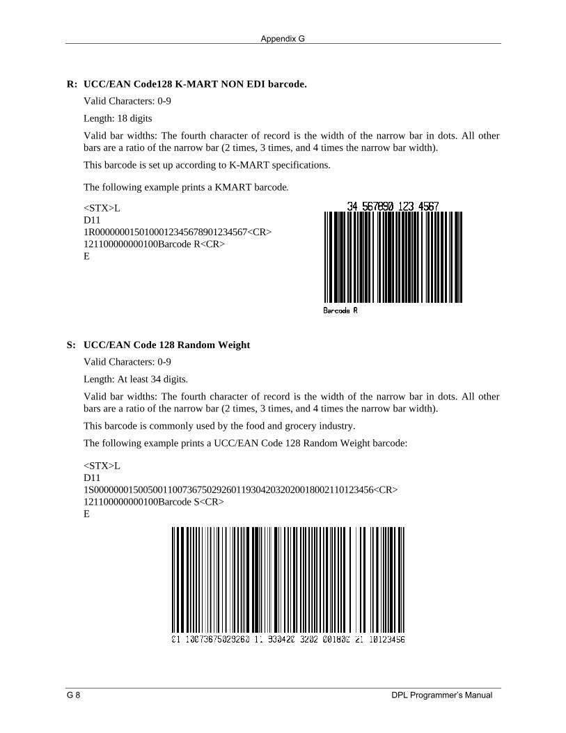
Appendix G
G 8 DPL Programmer’s Manual
R: UCC/EAN Code128 K-MART NON EDI barcode.
Valid Characters: 0-9
Length: 18 digits
Valid bar widths: The fourth character of record is the width of the narrow bar in dots. All otherbars are a ratio of the narrow bar (2 times, 3 times, and 4 times the narrow bar width).
This barcode is set up according to K-MART specifications.
The following example prints a KMART barcode.
<STX>LD111R0000000150100012345678901234567<CR>121100000000100Barcode R<CR>E
S: UCC/EAN Code 128 Random Weight
Valid Characters: 0-9
Length: At least 34 digits.
Valid bar widths: The fourth character of record is the width of the narrow bar in dots. All otherbars are a ratio of the narrow bar (2 times, 3 times, and 4 times the narrow bar width).
This barcode is commonly used by the food and grocery industry.
The following example prints a UCC/EAN Code 128 Random Weight barcode:
<STX>LD111S000000015005001100736750292601193042032020018002110123456<CR>121100000000100Barcode S<CR>E
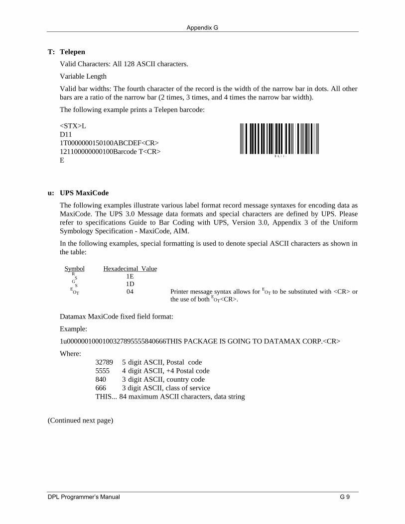
Appendix G
DPL Programmer’s Manual G 9
T: Telepen
Valid Characters: All 128 ASCII characters.
Variable Length
Valid bar widths: The fourth character of the record is the width of the narrow bar in dots. All otherbars are a ratio of the narrow bar (2 times, 3 times, and 4 times the narrow bar width).
The following example prints a Telepen barcode:
<STX>LD111T0000000150100ABCDEF<CR>121100000000100Barcode T<CR>E
u: UPS MaxiCode
The following examples illustrate various label format record message syntaxes for encoding data asMaxiCode. The UPS 3.0 Message data formats and special characters are defined by UPS. Pleaserefer to specifications Guide to Bar Coding with UPS, Version 3.0, Appendix 3 of the UniformSymbology Specification - MaxiCode, AIM.
In the following examples, special formatting is used to denote special ASCII characters as shown inthe table:
Symbol Hexadecimal ValueR
S 1EG
S 1DE
OT 04 Printer message syntax allows for EOT to be substituted with <CR> or
the use of both EOT<CR>.
Datamax MaxiCode fixed field format:
Example:
1u0000001000100327895555840666THIS PACKAGE IS GOING TO DATAMAX CORP.<CR>
Where:32789 5 digit ASCII, Postal code5555 4 digit ASCII, +4 Postal code840 3 digit ASCII, country code666 3 digit ASCII, class of serviceTHIS... 84 maximum ASCII characters, data string
(Continued next page)
Appendix G
G 10 DPL Programmer’s Manual
In the UPS 3.0 protocol examples that follow, Primary Message control characters GS will not be
encoded in the MaxiCode symbol. All characters, the Secondary Message, with the exception of theleading GS, in are encoded.
The UPS 3.0 zip + 4 with Message data format and message header:
Example:
1u0000001200120[)>RS01G
S96841706672GS840G
S001GS1Z12345675G
SUPSNGS12345EG
S089GGS1/1G
S10.1GSYG
SG
SG
SUTRS
EOT
Where:
[)>RS01G
S96 message header841706672 Maximum 9 alphanumeric ASCII,
Postal codePrimarymessage
840 country code001 ClassG
S1Z1... SecondaryMessage
...TRS
EOT
The UPS 3.0 international postal “V6C3E2” with Message data format and message header:
Example:
1u0000001200120[)>RS01G
S96V6C3E2GS068G
S001GS1Z12345675G
SUPSNGS12345EG
S089GGS1/1G
S10.1GSYG
SG
SG
SUTRS
EOT
Where:
[)>RS01G
S96 message headerV6C3E2 Maximum 6 alphanumeric ASCII,
International Zip codePrimarymessage
068 country code001 ClassG
S1Z1... SecondaryMessage
...TRS
EOT
The UPS 3.0 international zip “V6C3E2” without Message data format and message header:
Example:
1u0000001200120V6C3E2GS068G
S001GS1Z12345675G
SUPSNGS12345EG
S089GGS1/1G
S10.1GSYG
SG
SG
SUTRS
EOT
Where:
V6C3E2 maximum 6 alphanumeric ASCII,International Zip code
Primary message
068 country code001 ClassG
S1Z1... Secondary Message...TR
SE
OT
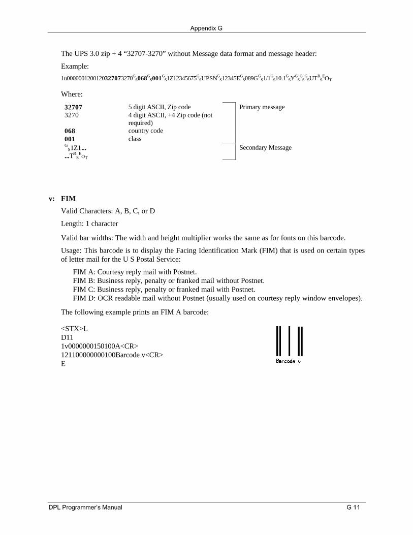
Appendix G
DPL Programmer’s Manual G 11
The UPS 3.0 zip + 4 “32707-3270” without Message data format and message header:
Example:
1u0000001200120327073270GS068G
S001GS1Z12345675G
SUPSNGS12345EG
S089GGS1/1G
S10.1GSYG
SG
SG
SUTRS
EOT
Where:
32707 5 digit ASCII, Zip code Primary message3270 4 digit ASCII, +4 Zip code (not
required)068 country code001 classG
S1Z1... Secondary Message...TR
SE
OT
v: FIM
Valid Characters: A, B, C, or D
Length: 1 character
Valid bar widths: The width and height multiplier works the same as for fonts on this barcode.
Usage: This barcode is to display the Facing Identification Mark (FIM) that is used on certain typesof letter mail for the U S Postal Service:
FIM A: Courtesy reply mail with Postnet.FIM B: Business reply, penalty or franked mail without Postnet.FIM C: Business reply, penalty or franked mail with Postnet.FIM D: OCR readable mail without Postnet (usually used on courtesy reply window envelopes).
The following example prints an FIM A barcode:
<STX>LD111v0000000150100A<CR>121100000000100Barcode v<CR>E
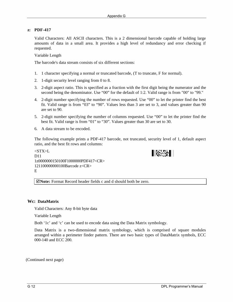
Appendix G
G 12 DPL Programmer’s Manual
z: PDF-417
Valid Characters: All ASCII characters. This is a 2 dimensional barcode capable of holding largeamounts of data in a small area. It provides a high level of redundancy and error checking ifrequested.
Variable Length
The barcode's data stream consists of six different sections:
1. 1 character specifying a normal or truncated barcode, (T to truncate, F for normal).
2. 1-digit security level ranging from 0 to 8.
3. 2-digit aspect ratio. This is specified as a fraction with the first digit being the numerator and thesecond being the denominator. Use “00” for the default of 1:2. Valid range is from "00" to "99."
4. 2-digit number specifying the number of rows requested. Use “00” to let the printer find the bestfit. Valid range is from “03” to “90”. Values less than 3 are set to 3, and values greater than 90are set to 90.
5. 2-digit number specifying the number of columns requested. Use “00” to let the printer find thebest fit. Valid range is from “01” to “30”. Values greater than 30 are set to 30.
6. A data stream to be encoded.
The following example prints a PDF-417 barcode, not truncated, security level of 1, default aspectratio, and the best fit rows and columns:
<STX>LD111z0000000150100F1000000PDF417<CR>121100000000100Barcode z<CR>E
þNote: Format Record header fields c and d should both be zero.
Wc: DataMatrix
Valid Characters: Any 8-bit byte data
Variable Length
Both ‘1c’ and ‘c’ can be used to encode data using the Data Matrix symbology.
Data Matrix is a two-dimensional matrix symbology, which is comprised of square modulesarranged within a perimeter finder pattern. There are two basic types of DataMatrix symbols, ECC000-140 and ECC 200.
(Continued next page)
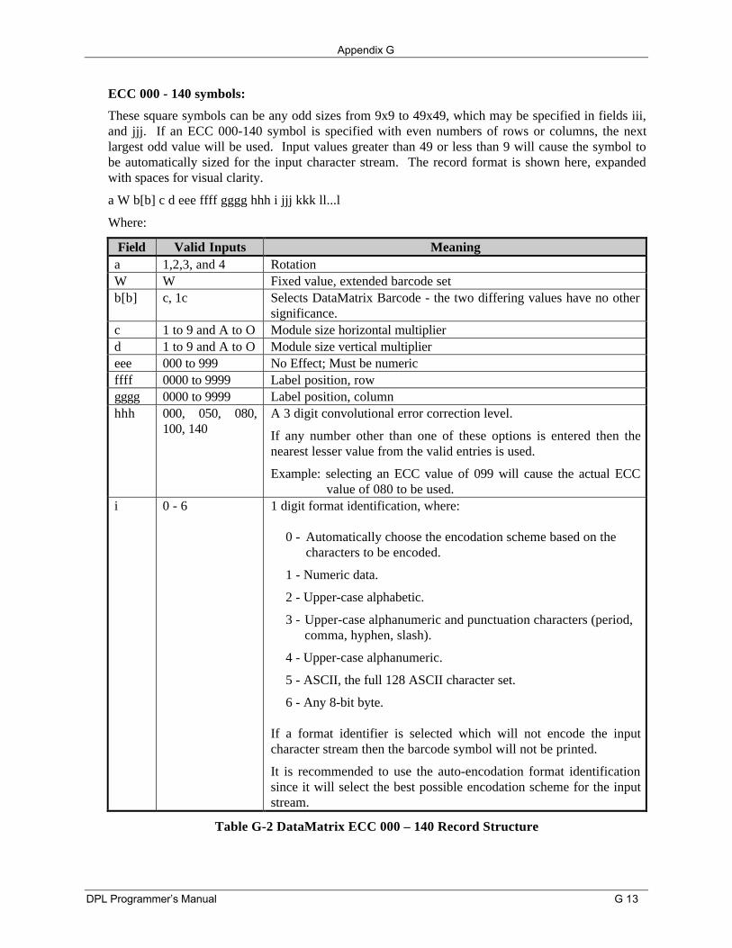
Appendix G
DPL Programmer’s Manual G 13
ECC 000 - 140 symbols:
These square symbols can be any odd sizes from 9x9 to 49x49, which may be specified in fields iii,and jjj. If an ECC 000-140 symbol is specified with even numbers of rows or columns, the nextlargest odd value will be used. Input values greater than 49 or less than 9 will cause the symbol tobe automatically sized for the input character stream. The record format is shown here, expandedwith spaces for visual clarity.
a W b[b] c d eee ffff gggg hhh i jjj kkk ll...l
Where:
Field Valid Inputs Meaninga 1,2,3, and 4 RotationW W Fixed value, extended barcode setb[b] c, 1c Selects DataMatrix Barcode - the two differing values have no other
significance.c 1 to 9 and A to O Module size horizontal multiplierd 1 to 9 and A to O Module size vertical multipliereee 000 to 999 No Effect; Must be numericffff 0000 to 9999 Label position, rowgggg 0000 to 9999 Label position, columnhhh 000, 050, 080,
100, 140A 3 digit convolutional error correction level.
If any number other than one of these options is entered then thenearest lesser value from the valid entries is used.
Example: selecting an ECC value of 099 will cause the actual ECCvalue of 080 to be used.
i 0 - 6 1 digit format identification, where:
0 - Automatically choose the encodation scheme based on the characters to be encoded.
1 - Numeric data.
2 - Upper-case alphabetic.
3 - Upper-case alphanumeric and punctuation characters (period, comma, hyphen, slash).
4 - Upper-case alphanumeric.
5 - ASCII, the full 128 ASCII character set.
6 - Any 8-bit byte.
If a format identifier is selected which will not encode the inputcharacter stream then the barcode symbol will not be printed.
It is recommended to use the auto-encodation format identificationsince it will select the best possible encodation scheme for the inputstream.
Table G-2 DataMatrix ECC 000 – 140 Record Structure
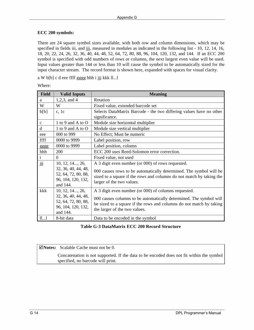
Appendix G
G 14 DPL Programmer’s Manual
ECC 200 symbols:
There are 24 square symbol sizes available, with both row and column dimensions, which may bespecified in fields iii, and jjj, measured in modules as indicated in the following list - 10, 12, 14, 16,18, 20, 22, 24, 26, 32, 36, 40, 44, 48, 52, 64, 72, 80, 88, 96, 104, 120, 132, and 144. If an ECC 200symbol is specified with odd numbers of rows or columns, the next largest even value will be used.Input values greater than 144 or less than 10 will cause the symbol to be automatically sized for theinput character stream. The record format is shown here, expanded with spaces for visual clarity.
a W b[b] c d eee ffff gggg hhh i jjj kkk ll...l
Where:
Field Valid Inputs Meaninga 1,2,3, and 4 RotationW W Fixed value, extended barcode setb[b] c, 1c Selects DataMatrix Barcode - the two differing values have no other
significance.c 1 to 9 and A to O Module size horizontal multiplierd 1 to 9 and A to O Module size vertical multipliereee 000 to 999 No Effect; Must be numericffff 0000 to 9999 Label position, rowgggg 0000 to 9999 Label position, columnhhh 200 ECC 200 uses Reed-Solomon error correction.i 0 Fixed value, not usedjjj 10, 12, 14..., 26,
32, 36, 40, 44, 48,52, 64, 72, 80, 88,96, 104, 120, 132,and 144.
A 3 digit even number (or 000) of rows requested.
000 causes rows to be automatically determined. The symbol will besized to a square if the rows and columns do not match by taking thelarger of the two values.
kkk 10, 12, 14..., 26,32, 36, 40, 44, 48,52, 64, 72, 80, 88,96, 104, 120, 132,and 144.
A 3 digit even number (or 000) of columns requested.
000 causes columns to be automatically determined. The symbol willbe sized to a square if the rows and columns do not match by takingthe larger of the two values.
ll...l 8-bit data Data to be encoded in the symbol
Table G-3 DataMatrix ECC 200 Record Structure
þNotes: Scalable Cache must not be 0.
Concatenation is not supported. If the data to be encoded does not fit within the symbolspecified, no barcode will print.
DPL Programmer’s Manual H 1
Appendix H
Font Mapping: Single Byte and Double Byte Characters
Label format records with font code 9 in the b field of the Format Record Header can specify any of thefollowing bit-mapped or scalable fonts with the associated specification in the font size/selection (eeeheight) field, as shown in the tables on the following pages.
Example: 191109600100010A0215134<CR>
The example above will produce a printed string consisting of the two Kanji characters referenced by thetwo HEX ASCII pairs A0, 21, and 51, 34, on appropriately equipped printers.
Example: 1911U4001000100P012P012<0x38><0x77><0x00>
The above example will produce a printed string consisting of the one 12 point Kanji characterreferenced by the byte pair with hex values 38 and 77 on appropriately equipped printers.
þNote: Double byte hex representations for Kanji character strings terminate with a null byte.
The alphanumeric portion (nn) of the scalable font specifiers, Snn, Unn, unn, numbering system is abase 62 numbering system, 0, 1, 2,...8, 9, A, B, C,...X, Y, Z, a, b, c,...x, y, z. For scalable fonts the Sdesignation signifies single byte characters and U designates double byte. The U lower case counterpartsignifies that print data in the label format record is in a Hex-ASCII format. A Hex-ASCII format for asingle byte with hex value 0xFF would be two ASCII character bytes FF (0x4646). Fonts that have beendownloaded with designators of the form nn, where nn are alphanumeric, as seen in the font sizespecifier (eee height) column below, may be referenced in label format records by their upper or lowercase specifiers as needed. However, fonts created for double-byte access cannot be accessed using Snnas the font designator, and vice versa, single-byte fonts cannot be accessed using Unn or unn.
(Continued next page)
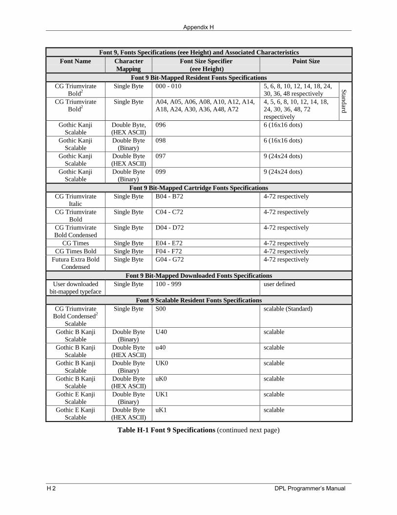
Appendix H
H 2 DPL Programmer’s Manual
Font 9, Fonts Specifications (eee Height) and Associated CharacteristicsFont Name Character
MappingFont Size Specifier
(eee Height)Point Size
Font 9 Bit-Mapped Resident Fonts SpecificationsCG Triumvirate
Bold2Single Byte 000 - 010 5, 6, 8, 10, 12, 14, 18, 24,
30, 36, 48 respectivelyCG Triumvirate
Bold2Single Byte A04, A05, A06, A08, A10, A12, A14,
A18, A24, A30, A36, A48, A724, 5, 6, 8, 10, 12, 14, 18,24, 30, 36, 48, 72respectively
Standard
Gothic KanjiScalable
Double Byte,(HEX ASCII)
096 6 (16x16 dots)
Gothic KanjiScalable
Double Byte(Binary)
098 6 (16x16 dots)
Gothic KanjiScalable
Double Byte(HEX ASCII)
097 9 (24x24 dots)
Gothic KanjiScalable
Double Byte(Binary)
099 9 (24x24 dots)
Font 9 Bit-Mapped Cartridge Fonts SpecificationsCG Triumvirate
ItalicSingle Byte B04 - B72 4-72 respectively
CG TriumvirateBold
Single Byte C04 - C72 4-72 respectively
CG TriumvirateBold Condensed
Single Byte D04 - D72 4-72 respectively
CG Times Single Byte E04 - E72 4-72 respectivelyCG Times Bold Single Byte F04 - F72 4-72 respectively
Futura Extra BoldCondensed
Single Byte G04 - G72 4-72 respectively
Font 9 Bit-Mapped Downloaded Fonts SpecificationsUser downloaded
bit-mapped typefaceSingle Byte 100 - 999 user defined
Font 9 Scalable Resident Fonts SpecificationsCG Triumvirate
Bold Condensed2
Scalable
Single Byte S00 scalable (Standard)
Gothic B KanjiScalable
Double Byte(Binary)
U40 scalable
Gothic B KanjiScalable
Double Byte(HEX ASCII)
u40 scalable
Gothic B KanjiScalable
Double Byte(Binary)
UK0 scalable
Gothic B KanjiScalable
Double Byte(HEX ASCII)
uK0 scalable
Gothic E KanjiScalable
Double Byte(Binary)
UK1 scalable
Gothic E KanjiScalable
Double Byte(HEX ASCII)
uK1 scalable
Table H-1 Font 9 Specifications (continued next page)
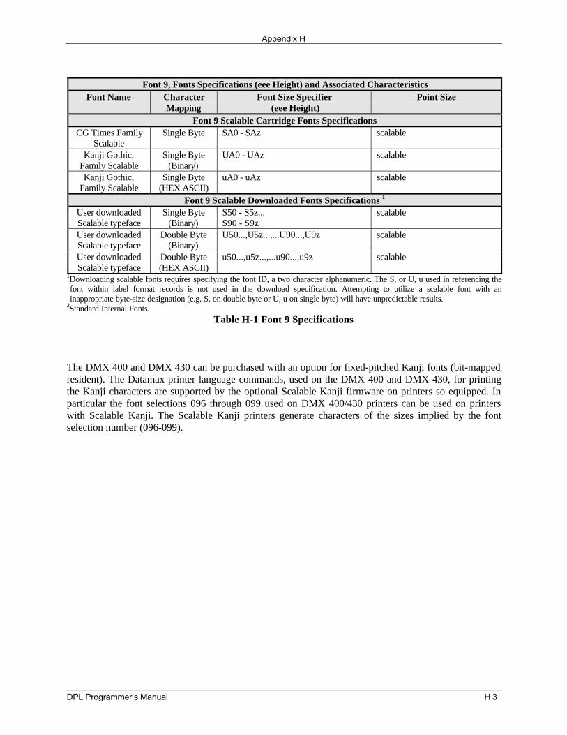
Appendix H
DPL Programmer’s Manual H 3
Font 9, Fonts Specifications (eee Height) and Associated CharacteristicsFont Name Character
MappingFont Size Specifier
(eee Height)Point Size
Font 9 Scalable Cartridge Fonts SpecificationsCG Times Family
ScalableSingle Byte SA0 - SAz scalable
Kanji Gothic,Family Scalable
Single Byte(Binary)
UA0 - UAz scalable
Kanji Gothic,Family Scalable
Single Byte(HEX ASCII)
uA0 - uAz scalable
Font 9 Scalable Downloaded Fonts Specifications 1
User downloadedScalable typeface
Single Byte(Binary)
S50 - S5z...S90 - S9z
scalable
User downloadedScalable typeface
Double Byte(Binary)
U50...,U5z...,...U90...,U9z scalable
User downloadedScalable typeface
Double Byte(HEX ASCII)
u50...,u5z...,...u90...,u9z scalable
1Downloading scalable fonts requires specifying the font ID, a two character alphanumeric. The S, or U, u used in referencing thefont within label format records is not used in the download specification. Attempting to utilize a scalable font with aninappropriate byte-size designation (e.g. S, on double byte or U, u on single byte) will have unpredictable results.
2Standard Internal Fonts.Table H-1 Font 9 Specifications
The DMX 400 and DMX 430 can be purchased with an option for fixed-pitched Kanji fonts (bit-mappedresident). The Datamax printer language commands, used on the DMX 400 and DMX 430, for printingthe Kanji characters are supported by the optional Scalable Kanji firmware on printers so equipped. Inparticular the font selections 096 through 099 used on DMX 400/430 printers can be used on printerswith Scalable Kanji. The Scalable Kanji printers generate characters of the sizes implied by the fontselection number (096-099).

Appendix H
H 4 DPL Programmer’s Manual
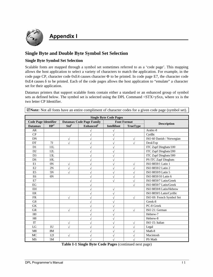
DPL Programmer’s Manual I 1
Appendix I
Single Byte and Double Byte Symbol Set SelectionSingle Byte Symbol Set SelectionScalable fonts are mapped through a symbol set sometimes referred to as a ‘code page’. This mappingallows the host application to select a variety of characters to match the application. For example, in thecode page CP, character code 0xE4 causes character Φ to be printed. In code page E7, the character code0xE4 causes δ to be printed. Each of the code pages allows the host application to “emulate” a characterset for their application.
Datamax printers that support scalable fonts contain either a standard or an enhanced group of symbolsets as defined below. The symbol set is selected using the DPL Command <STX>ySxx, where xx is thetwo letter CP Identifier.
þNote: Not all fonts have an entire compliment of character codes for a given code page (symbol set).
Single Byte Code PagesCode Page Identifier Datamax Code Page Family Font FormatDatamax HP1 Std2 Enhanced2 Intellifont TrueType
Description
AR √ √ Arabic-8CP √ √ CyrillicDN √ √ √ √ ISO 60 Danish / NorwegianDT 7J √ √ √ √ DeskTopD1 11L √ √ ITC Zapf Dingbats/100D2 12L √ √ ITC Zapf Dingbats/200D3 13L √ √ ITC Zapf Dingbats/300DS 10L √ √ PS ITC Zapf DingbatsE1 0N √ √ √ √ ISO 8859/1 Latin 1E2 2N √ √ √ √ ISO 8859/2 Latin 2E5 5N √ √ √ √ ISO 8859/9 Latin 5E6 6N √ √ √ ISO 8859/10 Latin 6E7 √ √ √ ISO 8859/7 Latin/GreekEG √ √ ISO 8859/7 Latin/GreekEH √ √ ISO 8859/8 Latin/HebrewER √ √ ISO 8859/5 Latin/CyrillicFR √ √ √ √ ISO 69: French Symbol SetG8 √ √ Greek-8GK √ √ PC-8 GreekGR √ √ √ √ ISO 21: GermanH0 √ √ Hebrew-7H8 √ √ Hebrew-8IT √ √ √ √ ISO 15: ItalianLG 1U √ √ √ √ LegalM8 8M √ √ √ Math-8MC 12J √ √ √ √ MacintoshMS 5M √ √ √ PS Math
Table I-1 Single Byte Code Pages (continued next page)
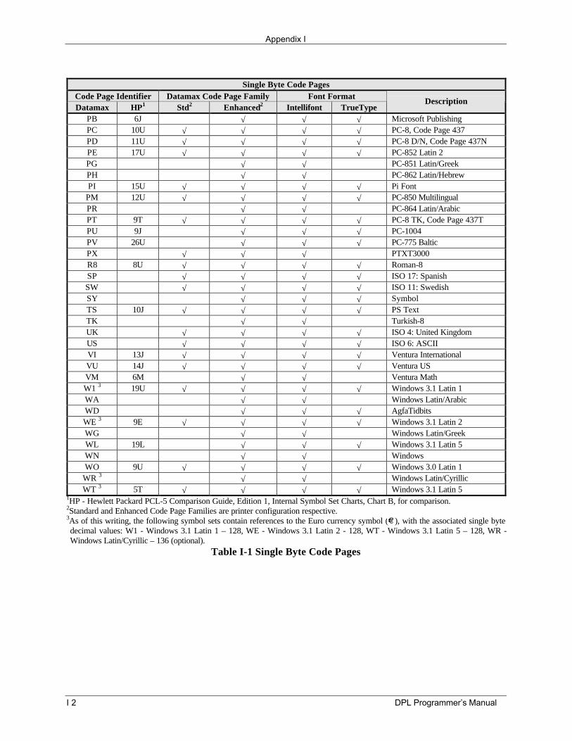
Appendix I
I 2 DPL Programmer’s Manual
Single Byte Code PagesCode Page Identifier Datamax Code Page Family Font FormatDatamax HP1 Std2 Enhanced2 Intellifont TrueType
Description
PB 6J √ √ √ Microsoft PublishingPC 10U √ √ √ √ PC-8, Code Page 437PD 11U √ √ √ √ PC-8 D/N, Code Page 437NPE 17U √ √ √ √ PC-852 Latin 2PG √ √ PC-851 Latin/GreekPH √ √ PC-862 Latin/HebrewPI 15U √ √ √ √ Pi Font
PM 12U √ √ √ √ PC-850 MultilingualPR √ √ PC-864 Latin/ArabicPT 9T √ √ √ √ PC-8 TK, Code Page 437TPU 9J √ √ √ PC-1004PV 26U √ √ √ PC-775 BalticPX √ √ √ PTXT3000R8 8U √ √ √ √ Roman-8SP √ √ √ √ ISO 17: SpanishSW √ √ √ √ ISO 11: SwedishSY √ √ √ SymbolTS 10J √ √ √ √ PS TextTK √ √ Turkish-8UK √ √ √ √ ISO 4: United KingdomUS √ √ √ √ ISO 6: ASCIIVI 13J √ √ √ √ Ventura InternationalVU 14J √ √ √ √ Ventura USVM 6M √ √ Ventura MathW1 3 19U √ √ √ √ Windows 3.1 Latin 1WA √ √ Windows Latin/ArabicWD √ √ √ AgfaTidbitsWE 3 9E √ √ √ √ Windows 3.1 Latin 2WG √ √ Windows Latin/GreekWL 19L √ √ √ Windows 3.1 Latin 5WN √ √ WindowsWO 9U √ √ √ √ Windows 3.0 Latin 1
WR 3 √ √ Windows Latin/CyrillicWT 3 5T √ √ √ √ Windows 3.1 Latin 5
1HP - Hewlett Packard PCL-5 Comparison Guide, Edition 1, Internal Symbol Set Charts, Chart B, for comparison.2Standard and Enhanced Code Page Families are printer configuration respective.3As of this writing, the following symbol sets contain references to the Euro currency symbol ( ), with the associated single bytedecimal values: W1 - Windows 3.1 Latin 1 – 128, WE - Windows 3.1 Latin 2 - 128, WT - Windows 3.1 Latin 5 – 128, WR -Windows Latin/Cyrillic – 136 (optional).
Table I-1 Single Byte Code Pages
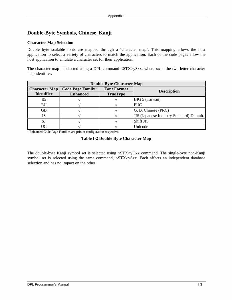
Appendix I
DPL Programmer’s Manual I 3
Double-Byte Symbols, Chinese, Kanji
Character Map Selection
Double byte scalable fonts are mapped through a ‘character map’. This mapping allows the hostapplication to select a variety of characters to match the application. Each of the code pages allow thehost application to emulate a character set for their application.
The character map is selected using a DPL command <STX>ySxx, where xx is the two-letter charactermap identifier.
Double Byte Character MapCode Page Family1 Font FormatCharacter Map
Identifier Enhanced TrueTypeDescription
B5 √ √ BIG 5 (Taiwan)EU √ √ EUCGB √ √ G. B. Chinese (PRC)JS √ √ JIS (Japanese Industry Standard) Default.SJ √ √ Shift JISUC √ √ Unicode
1 Enhanced Code Page Families are printer configuration respective.
Table I-2 Double Byte Character Map
The double-byte Kanji symbol set is selected using <STX>yUxx command. The single-byte non-Kanjisymbol set is selected using the same command, <STX>ySxx. Each affects an independent databaseselection and has no impact on the other.

Appendix I
I 4 DPL Programmer’s Manual
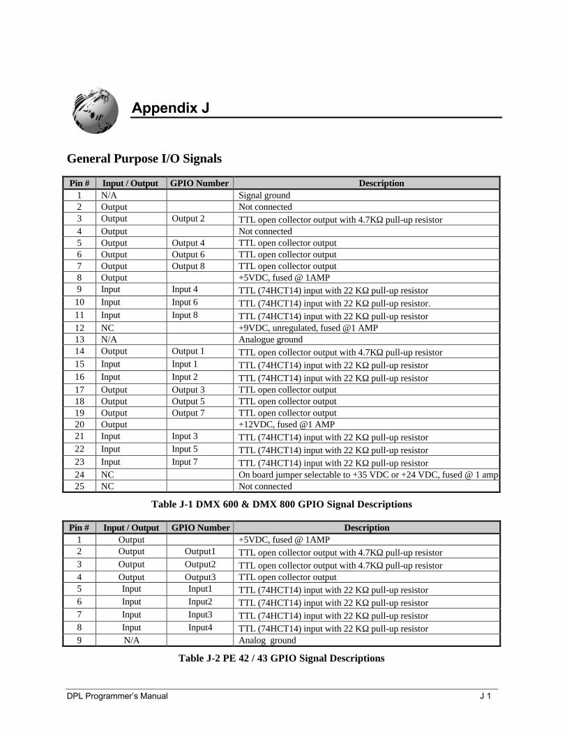
DPL Programmer’s Manual J 1
Appendix J
General Purpose I/O Signals
Pin # Input / Output GPIO Number Description1 N/A Signal ground2 Output Not connected3 Output Output 2 TTL open collector output with 4.7KΩ pull-up resistor4 Output Not connected5 Output Output 4 TTL open collector output6 Output Output 6 TTL open collector output7 Output Output 8 TTL open collector output8 Output +5VDC, fused @ 1AMP9 Input Input 4 TTL (74HCT14) input with 22 KΩ pull-up resistor10 Input Input 6 TTL (74HCT14) input with 22 KΩ pull-up resistor.11 Input Input 8 TTL (74HCT14) input with 22 KΩ pull-up resistor12 NC +9VDC, unregulated, fused @1 AMP13 N/A Analogue ground14 Output Output 1 TTL open collector output with 4.7KΩ pull-up resistor15 Input Input 1 TTL (74HCT14) input with 22 KΩ pull-up resistor16 Input Input 2 TTL (74HCT14) input with 22 KΩ pull-up resistor17 Output Output 3 TTL open collector output18 Output Output 5 TTL open collector output19 Output Output 7 TTL open collector output20 Output +12VDC, fused @1 AMP21 Input Input 3 TTL (74HCT14) input with 22 KΩ pull-up resistor22 Input Input 5 TTL (74HCT14) input with 22 KΩ pull-up resistor23 Input Input 7 TTL (74HCT14) input with 22 KΩ pull-up resistor24 NC On board jumper selectable to +35 VDC or +24 VDC, fused @ 1 amp25 NC Not connected
Table J-1 DMX 600 & DMX 800 GPIO Signal Descriptions
Pin # Input / Output GPIO Number Description1 Output +5VDC, fused @ 1AMP2 Output Output1 TTL open collector output with 4.7KΩ pull-up resistor3 Output Output2 TTL open collector output with 4.7KΩ pull-up resistor4 Output Output3 TTL open collector output5 Input Input1 TTL (74HCT14) input with 22 KΩ pull-up resistor6 Input Input2 TTL (74HCT14) input with 22 KΩ pull-up resistor7 Input Input3 TTL (74HCT14) input with 22 KΩ pull-up resistor8 Input Input4 TTL (74HCT14) input with 22 KΩ pull-up resistor9 N/A Analog ground
Table J-2 PE 42 / 43 GPIO Signal Descriptions
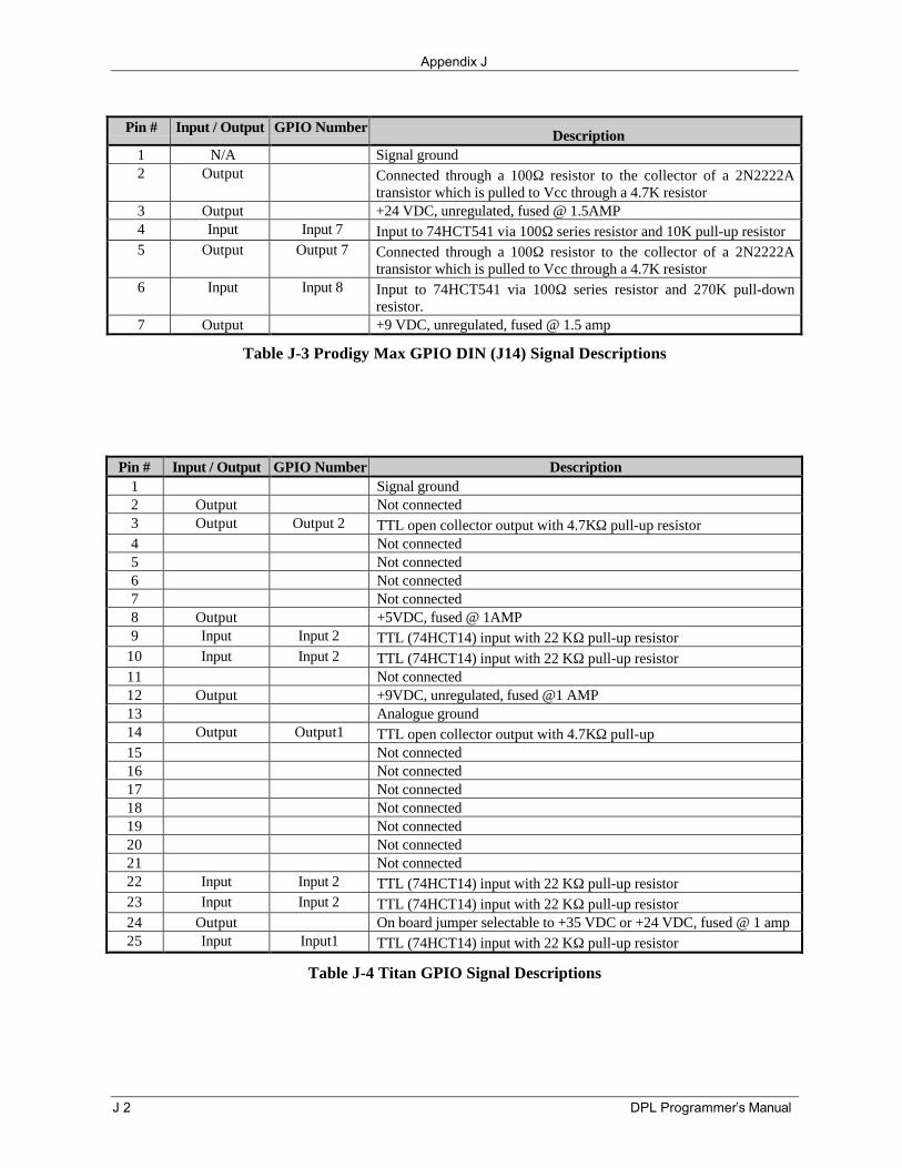
Appendix J
J 2 DPL Programmer’s Manual
Pin # Input / Output GPIO Number Description1 N/A Signal ground2 Output Connected through a 100Ω resistor to the collector of a 2N2222A
transistor which is pulled to Vcc through a 4.7K resistor3 Output +24 VDC, unregulated, fused @ 1.5AMP4 Input Input 7 Input to 74HCT541 via 100Ω series resistor and 10K pull-up resistor5 Output Output 7 Connected through a 100Ω resistor to the collector of a 2N2222A
transistor which is pulled to Vcc through a 4.7K resistor6 Input Input 8 Input to 74HCT541 via 100Ω series resistor and 270K pull-down
resistor.7 Output +9 VDC, unregulated, fused @ 1.5 amp
Table J-3 Prodigy Max GPIO DIN (J14) Signal Descriptions
Pin # Input / Output GPIO Number Description1 Signal ground2 Output Not connected3 Output Output 2 TTL open collector output with 4.7KΩ pull-up resistor4 Not connected5 Not connected6 Not connected7 Not connected8 Output +5VDC, fused @ 1AMP9 Input Input 2 TTL (74HCT14) input with 22 KΩ pull-up resistor
10 Input Input 2 TTL (74HCT14) input with 22 KΩ pull-up resistor11 Not connected12 Output +9VDC, unregulated, fused @1 AMP13 Analogue ground14 Output Output1 TTL open collector output with 4.7KΩ pull-up15 Not connected16 Not connected17 Not connected18 Not connected19 Not connected20 Not connected21 Not connected22 Input Input 2 TTL (74HCT14) input with 22 KΩ pull-up resistor23 Input Input 2 TTL (74HCT14) input with 22 KΩ pull-up resistor24 Output On board jumper selectable to +35 VDC or +24 VDC, fused @ 1 amp25 Input Input1 TTL (74HCT14) input with 22 KΩ pull-up resistor
Table J-4 Titan GPIO Signal Descriptions
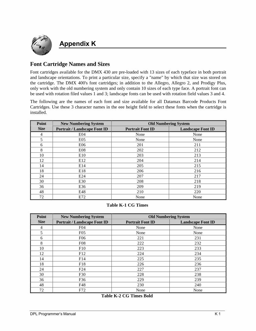
DPL Programmer’s Manual K 1
Appendix K
Font Cartridge Names and SizesFont cartridges available for the DMX 430 are pre-loaded with 13 sizes of each typeface in both portraitand landscape orientations. To print a particular size, specify a "name" by which that size was stored onthe cartridge. The DMX 400's font cartridges; in addition to the Allegro, Allegro 2, and Prodigy Plus,only work with the old numbering system and only contain 10 sizes of each type face. A portrait font canbe used with rotation filed values 1 and 3; landscape fonts can be used with rotation field values 3 and 4.
The following are the names of each font and size available for all Datamax Barcode Products FontCartridges. Use these 3 character names in the eee height field to select these fonts when the cartridge isinstalled.
New Numbering System Old Numbering SystemPointSize Portrait / Landscape Font ID Portrait Font ID Landscape Font ID
4 E04 None None5 E05 None None6 E06 201 2118 E08 202 21210 E10 203 21312 E12 204 21414 E14 205 21518 E18 206 21624 E24 207 21730 E30 208 21836 E36 209 21948 E48 210 22072 E72 None None
Table K-1 CG Times
New Numbering System Old Numbering SystemPointSize Portrait / Landscape Font ID Portrait Font ID Landscape Font ID
4 F04 None None5 F05 None None6 F06 221 2318 F08 222 23210 F10 223 23312 F12 224 23414 F14 225 23518 F18 226 23624 F24 227 23730 F30 228 23836 F36 229 23948 F48 230 24072 F72 None None
Table K-2 CG Times Bold
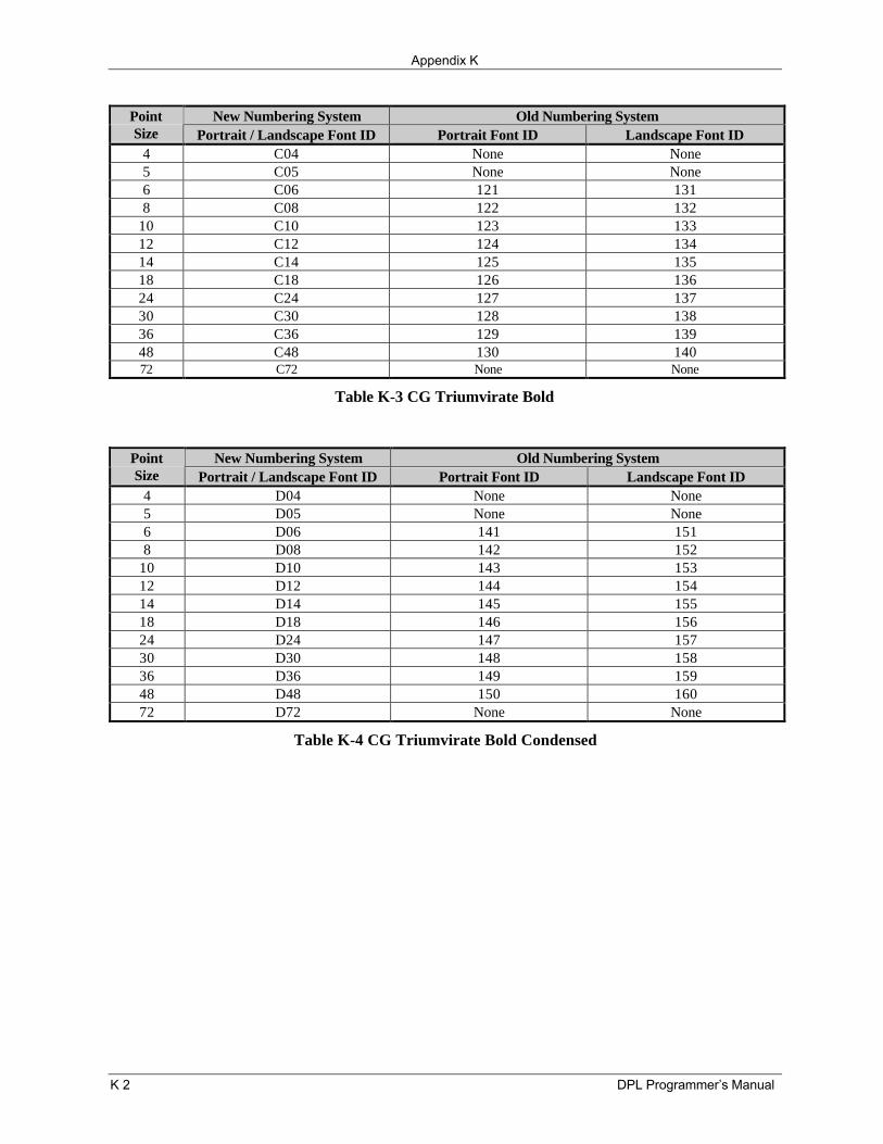
Appendix K
K 2 DPL Programmer’s Manual
New Numbering System Old Numbering SystemPointSize Portrait / Landscape Font ID Portrait Font ID Landscape Font ID
4 C04 None None5 C05 None None6 C06 121 1318 C08 122 132
10 C10 123 13312 C12 124 13414 C14 125 13518 C18 126 13624 C24 127 13730 C30 128 13836 C36 129 13948 C48 130 14072 C72 None None
Table K-3 CG Triumvirate Bold
New Numbering System Old Numbering SystemPointSize Portrait / Landscape Font ID Portrait Font ID Landscape Font ID
4 D04 None None5 D05 None None6 D06 141 1518 D08 142 152
10 D10 143 15312 D12 144 15414 D14 145 15518 D18 146 15624 D24 147 15730 D30 148 15836 D36 149 15948 D48 150 16072 D72 None None
Table K-4 CG Triumvirate Bold Condensed
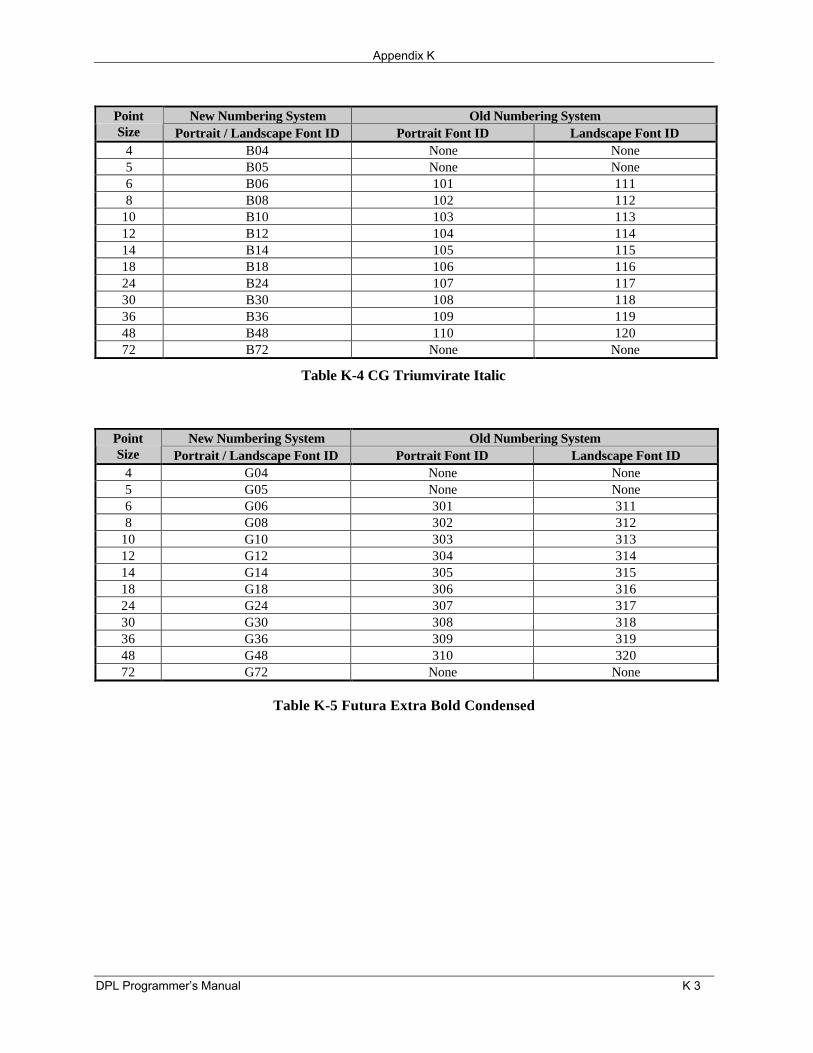
Appendix K
DPL Programmer’s Manual K 3
New Numbering System Old Numbering SystemPointSize Portrait / Landscape Font ID Portrait Font ID Landscape Font ID
4 B04 None None5 B05 None None6 B06 101 1118 B08 102 112
10 B10 103 11312 B12 104 11414 B14 105 11518 B18 106 11624 B24 107 11730 B30 108 11836 B36 109 11948 B48 110 12072 B72 None None
Table K-4 CG Triumvirate Italic
New Numbering System Old Numbering SystemPointSize Portrait / Landscape Font ID Portrait Font ID Landscape Font ID
4 G04 None None5 G05 None None6 G06 301 3118 G08 302 312
10 G10 303 31312 G12 304 31414 G14 305 31518 G18 306 31624 G24 307 31730 G30 308 31836 G36 309 31948 G48 310 32072 G72 None None
Table K-5 Futura Extra Bold Condensed

Appendix K
K 4 DPL Programmer’s Manual
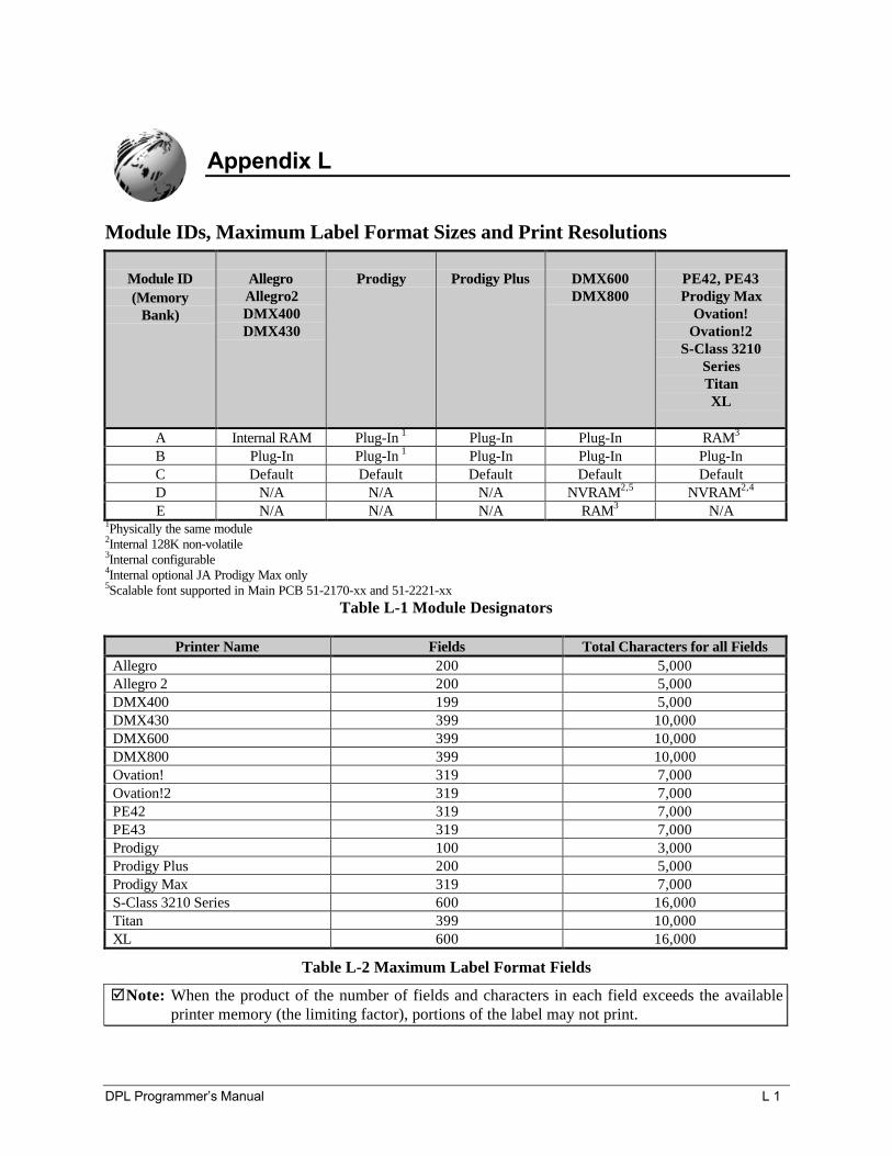
DPL Programmer’s Manual L 1
Appendix L
Module IDs, Maximum Label Format Sizes and Print Resolutions
Module ID(Memory
Bank)
AllegroAllegro2DMX400DMX430
Prodigy Prodigy Plus DMX600DMX800
PE42, PE43Prodigy Max
Ovation!Ovation!2
S-Class 3210SeriesTitanXL
A Internal RAM Plug-In 1 Plug-In Plug-In RAM3
B Plug-In Plug-In 1 Plug-In Plug-In Plug-InC Default Default Default Default DefaultD N/A N/A N/A NVRAM2,5 NVRAM2,4
E N/A N/A N/A RAM3 N/A1Physically the same module2Internal 128K non-volatile3Internal configurable4Internal optional JA Prodigy Max only5Scalable font supported in Main PCB 51-2170-xx and 51-2221-xx
Table L-1 Module Designators
Printer Name Fields Total Characters for all FieldsAllegro 200 5,000Allegro 2 200 5,000DMX400 199 5,000DMX430 399 10,000DMX600 399 10,000DMX800 399 10,000Ovation! 319 7,000Ovation!2 319 7,000PE42 319 7,000PE43 319 7,000Prodigy 100 3,000Prodigy Plus 200 5,000Prodigy Max 319 7,000S-Class 3210 Series 600 16,000Titan 399 10,000XL 600 16,000
Table L-2 Maximum Label Format Fields
þNote: When the product of the number of fields and characters in each field exceeds the availableprinter memory (the limiting factor), portions of the label may not print.
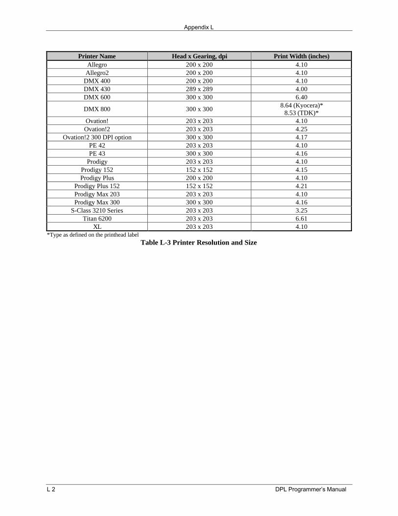
Appendix L
L 2 DPL Programmer’s Manual
Printer Name Head x Gearing, dpi Print Width (inches)Allegro 200 x 200 4.10Allegro2 200 x 200 4.10
DMX 400 200 x 200 4.10DMX 430 289 x 289 4.00DMX 600 300 x 300 6.40
DMX 800 300 x 300 8.64 (Kyocera)*8.53 (TDK)*
Ovation! 203 x 203 4.10Ovation!2 203 x 203 4.25
Ovation!2 300 DPI option 300 x 300 4.17PE 42 203 x 203 4.10PE 43 300 x 300 4.16
Prodigy 203 x 203 4.10Prodigy 152 152 x 152 4.15Prodigy Plus 200 x 200 4.10
Prodigy Plus 152 152 x 152 4.21Prodigy Max 203 203 x 203 4.10Prodigy Max 300 300 x 300 4.16
S-Class 3210 Series 203 x 203 3.25Titan 6200 203 x 203 6.61
XL 203 x 203 4.10*Type as defined on the printhead label
Table L-3 Printer Resolution and Size
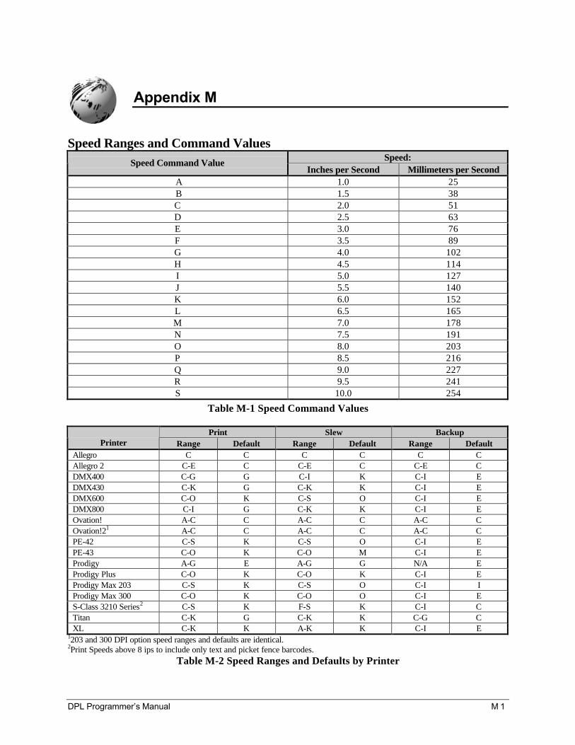
DPL Programmer’s Manual M 1
Appendix M
Speed Ranges and Command ValuesSpeed:Speed Command Value
Inches per Second Millimeters per SecondA 1.0 25B 1.5 38C 2.0 51D 2.5 63E 3.0 76F 3.5 89G 4.0 102H 4.5 114I 5.0 127J 5.5 140K 6.0 152L 6.5 165M 7.0 178N 7.5 191O 8.0 203P 8.5 216Q 9.0 227R 9.5 241S 10.0 254
Table M-1 Speed Command Values
Print Slew BackupPrinter Range Default Range Default Range Default
Allegro C C C C C CAllegro 2 C-E C C-E C C-E CDMX400 C-G G C-I K C-I EDMX430 C-K G C-K K C-I EDMX600 C-O K C-S O C-I EDMX800 C-I G C-K K C-I EOvation! A-C C A-C C A-C COvation!21 A-C C A-C C A-C CPE-42 C-S K C-S O C-I EPE-43 C-O K C-O M C-I EProdigy A-G E A-G G N/A EProdigy Plus C-O K C-O K C-I EProdigy Max 203 C-S K C-S O C-I IProdigy Max 300 C-O K C-O O C-I ES-Class 3210 Series2 C-S K F-S K C-I CTitan C-K G C-K K C-G CXL C-K K A-K K C-I E
1203 and 300 DPI option speed ranges and defaults are identical.2Print Speeds above 8 ips to include only text and picket fence barcodes.
Table M-2 Speed Ranges and Defaults by Printer

Appendix M
M 2 DPL Programmer’s Manual
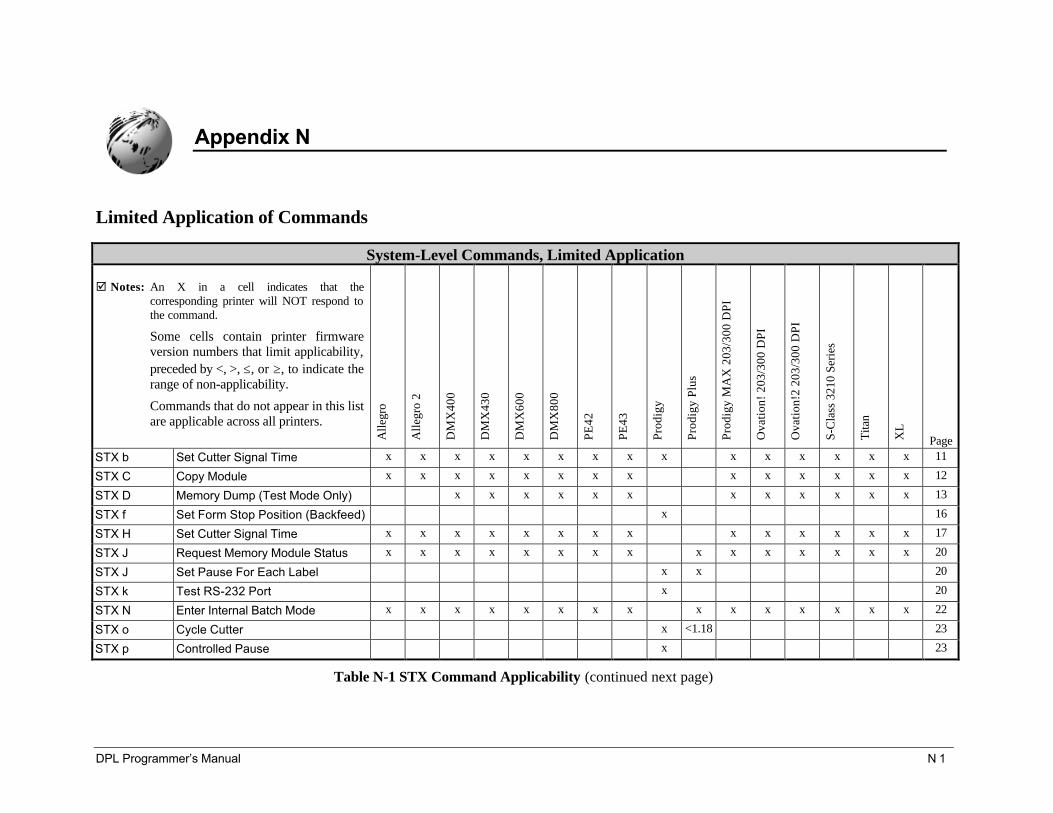
DPL Programmer’s Manual N 1
Appendix N
Limited Application of Commands
System-Level Commands, Limited Application
þ Notes: An X in a cell indicates that thecorresponding printer will NOT respond tothe command.
Some cells contain printer firmwareversion numbers that limit applicability,preceded by <, >, ≤, or ≥, to indicate therange of non-applicability.
Commands that do not appear in this listare applicable across all printers.
Alle
gro
Alle
gro
2
DM
X40
0
DM
X43
0
DM
X60
0
DM
X80
0
PE42
PE43
Prod
igy
Prod
igy
Plus
Prod
igy
MA
X 2
03/3
00 D
PI
Ova
tion!
203
/300
DPI
Ova
tion!
2 20
3/30
0 D
PI
S-C
lass
321
0 Se
ries
Tita
n
XL
PageSTX b Set Cutter Signal Time x x x x x x x x x x x x x x x 11
STX C Copy Module x x x x x x x x x x x x x x 12
STX D Memory Dump (Test Mode Only) x x x x x x x x x x x x 13
STX f Set Form Stop Position (Backfeed) x 16
STX H Set Cutter Signal Time x x x x x x x x x x x x x x 17
STX J Request Memory Module Status x x x x x x x x x x x x x x x 20
STX J Set Pause For Each Label x x 20
STX k Test RS-232 Port x 20
STX N Enter Internal Batch Mode x x x x x x x x x x x x x x x 22
STX o Cycle Cutter x <1.18 23
STX p Controlled Pause x 23
Table N-1 STX Command Applicability (continued next page)
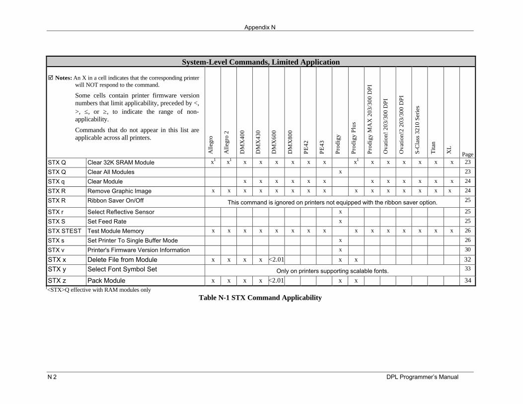
Appendix N
N 2 DPL Programmer’s Manual
System-Level Commands, Limited Application
þ Notes: An X in a cell indicates that the corresponding printerwill NOT respond to the command.
Some cells contain printer firmware versionnumbers that limit applicability, preceded by <,>, ≤, or ≥, to indicate the range of non-applicability.
Commands that do not appear in this list areapplicable across all printers.
Alle
gro
Alle
gro
2
DM
X40
0
DM
X43
0
DM
X60
0
DM
X80
0
PE42
PE43
Prod
igy
Prod
igy
Plus
Prod
igy
MA
X 2
03/3
00 D
PI
Ova
tion!
203
/300
DPI
Ova
tion!
2 20
3/30
0 D
PI
S-C
lass
321
0 Se
ries
Tita
n
XL
PageSTX Q Clear 32K SRAM Module x1 x1 x x x x x x x1 x x x x x x 23
STX Q Clear All Modules x 23
STX q Clear Module x x x x x x x x x x x x 24
STX R Remove Graphic Image x x x x x x x x x x x x x x x 24
STX R Ribbon Saver On/Off This command is ignored on printers not equipped with the ribbon saver option. 25
STX r Select Reflective Sensor x 25
STX S Set Feed Rate x 25
STX STEST Test Module Memory x x x x x x x x x x x x x x x 26
STX s Set Printer To Single Buffer Mode x 26
STX v Printer's Firmware Version Information x 30
STX x Delete File from Module x x x x <2.01 x x 32STX y Select Font Symbol Set Only on printers supporting scalable fonts. 33
STX z Pack Module x x x x <2.01 x x 341<STX>Q effective with RAM modules only
Table N-1 STX Command Applicability
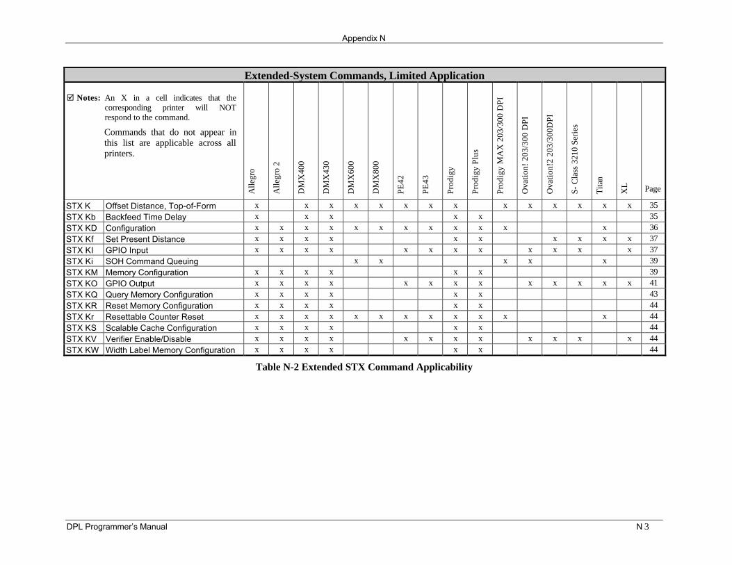
Appendix N
DPL Programmer’s Manual N 3
Extended-System Commands, Limited Application
þ Notes: An X in a cell indicates that thecorresponding printer will NOTrespond to the command.
Commands that do not appear inthis list are applicable across allprinters.
Alle
gro
Alle
gro
2
DM
X40
0
DM
X43
0
DM
X60
0
DM
X80
0
PE42
PE43
Prod
igy
Prod
igy
Plus
Prod
igy
MA
X 2
03/3
00 D
PI
Ova
tion!
203
/300
DPI
Ova
tion!
2 20
3/30
0DPI
S- C
lass
321
0 Se
ries
Tita
n
XL Page
STX K Offset Distance, Top-of-Form x x x x x x x x x x x x x x 35STX Kb Backfeed Time Delay x x x x x 35STX KD Configuration x x x x x x x x x x x x 36STX Kf Set Present Distance x x x x x x x x x x 37STX KI GPIO Input x x x x x x x x x x x x 37STX Ki SOH Command Queuing x x x x x 39STX KM Memory Configuration x x x x x x 39STX KO GPIO Output x x x x x x x x x x x x x 41STX KQ Query Memory Configuration x x x x x x 43STX KR Reset Memory Configuration x x x x x x 44STX Kr Resettable Counter Reset x x x x x x x x x x x x 44STX KS Scalable Cache Configuration x x x x x x 44STX KV Verifier Enable/Disable x x x x x x x x x x x x 44STX KW Width Label Memory Configuration x x x x x x 44
Table N-2 Extended STX Command Applicability
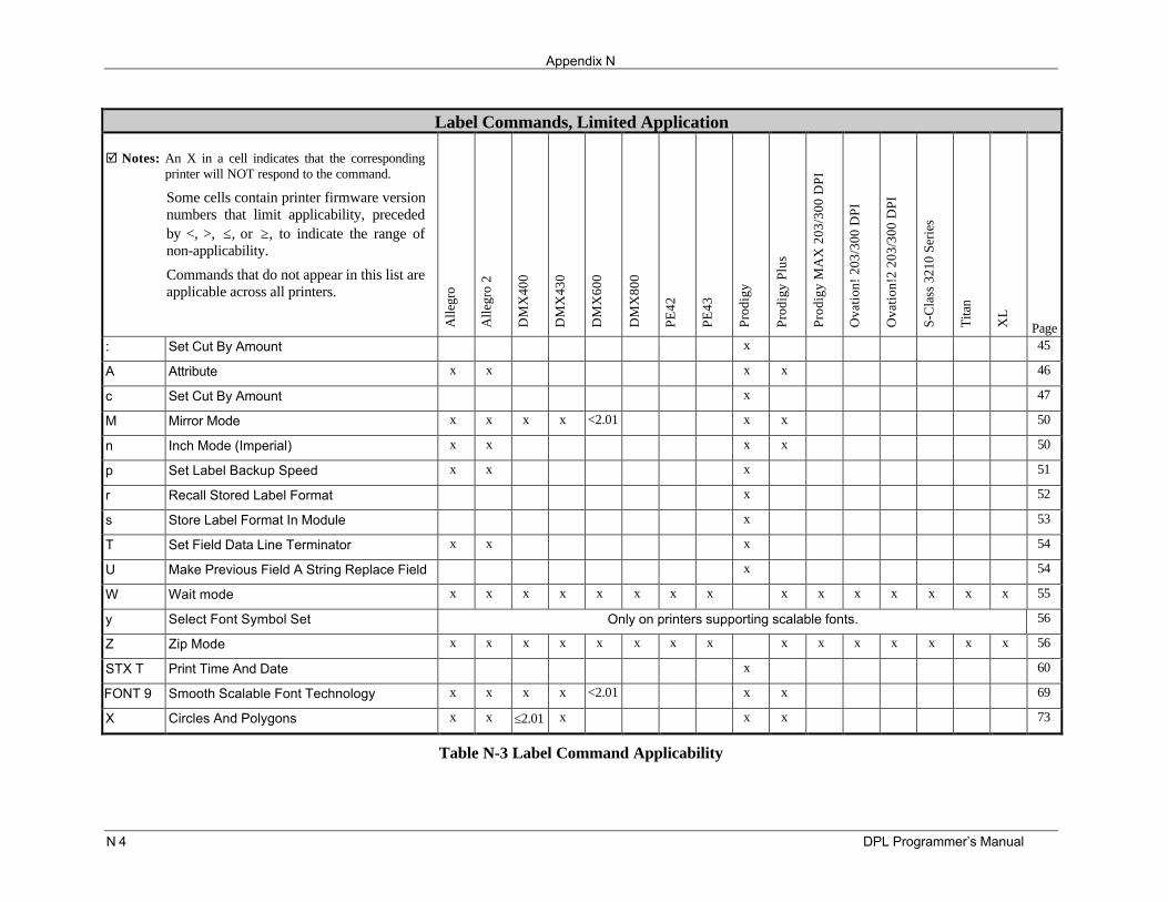
Appendix N
N 4 DPL Programmer’s Manual
Label Commands, Limited Application
þ Notes: An X in a cell indicates that the correspondingprinter will NOT respond to the command.
Some cells contain printer firmware versionnumbers that limit applicability, precededby <, >, ≤, or ≥, to indicate the range ofnon-applicability.
Commands that do not appear in this list areapplicable across all printers.
Alle
gro
Alle
gro
2
DM
X40
0
DM
X43
0
DM
X60
0
DM
X80
0
PE42
PE43
Prod
igy
Prod
igy
Plus
Prod
igy
MA
X 2
03/3
00 D
PI
Ova
tion!
203
/300
DPI
Ova
tion!
2 20
3/30
0 D
PI
S-C
lass
321
0 Se
ries
Tita
n
XL
Page: Set Cut By Amount x 45
A Attribute x x x x 46
c Set Cut By Amount x 47
M Mirror Mode x x x x <2.01 x x 50
n Inch Mode (Imperial) x x x x 50
p Set Label Backup Speed x x x 51
r Recall Stored Label Format x 52
s Store Label Format In Module x 53
T Set Field Data Line Terminator x x x 54
U Make Previous Field A String Replace Field x 54
W Wait mode x x x x x x x x x x x x x x x 55
y Select Font Symbol Set Only on printers supporting scalable fonts. 56
Z Zip Mode x x x x x x x x x x x x x x x 56
STX T Print Time And Date x 60
FONT 9 Smooth Scalable Font Technology x x x x <2.01 x x 69
X Circles And Polygons x x ≤2.01 x x x 73
Table N-3 Label Command Applicability
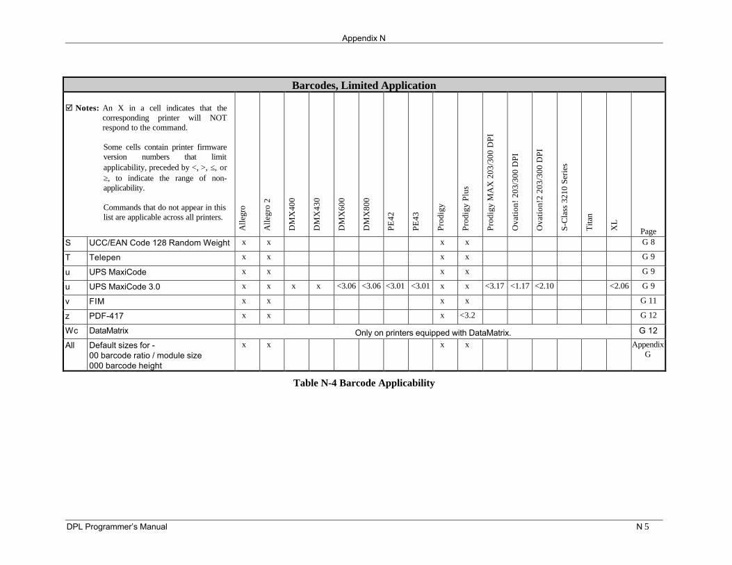
Appendix N
DPL Programmer’s Manual N 5
Barcodes, Limited Application
þ Notes: An X in a cell indicates that thecorresponding printer will NOTrespond to the command.
Some cells contain printer firmwareversion numbers that limitapplicability, preceded by <, >, ≤, or≥, to indicate the range of non-applicability.
Commands that do not appear in thislist are applicable across all printers.
Alle
gro
Alle
gro
2
DM
X40
0
DM
X43
0
DM
X60
0
DM
X80
0
PE42
PE43
Prod
igy
Prod
igy
Plus
Prod
igy
MA
X 2
03/3
00 D
PI
Ova
tion!
203
/300
DPI
Ova
tion!
2 20
3/30
0 D
PI
S-C
lass
321
0 Se
ries
Tita
n
XL
PageS UCC/EAN Code 128 Random Weight x x x x G 8
T Telepen x x x x G 9
u UPS MaxiCode x x x x G 9
u UPS MaxiCode 3.0 x x x x <3.06 <3.06 <3.01 <3.01 x x <3.17 <1.17 <2.10 <2.06 G 9
v FIM x x x x G 11
z PDF-417 x x x <3.2 G 12
Wc DataMatrix Only on printers equipped with DataMatrix. G 12
All Default sizes for -00 barcode ratio / module size000 barcode height
x x x x AppendixG
Table N-4 Barcode Applicability
Appendix N
N 6 DPL Programmer’s Manual
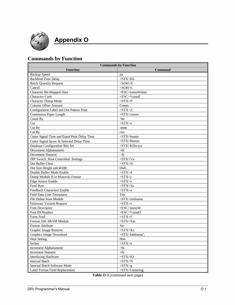
DPL Programmer’s Manual O 1
Appendix O
Commands by FunctionCommands by Function
Function CommandBackup Speed paBackfeed Time Delay <STX>KbBatch Quantity Request <SOH>ECancel <SOH>CCharacter Bit-Mapped Data <ESC>(snnnWdataCharacter Code <ESC>*cnnnECharacter Dump Mode <STX>PColumn Offset Amount CnnnnConfiguration Label and Dot Pattern Print <STX>ZContinuous Paper Length <STX>cnnnnCount By ^nnCut <STX>oCut By :nnnnCut By cnnCutter Signal Time and Equal Print Delay Time <STX>bnnnnCutter Signal 5µsec & Selected Delay Time <STX>HnnnnDatabase Configuration Bits Set <STX>KDwxyzDecrement Alphanumeric <fiiDecrement Numeric - fiiDIP Switch, Host Controlled Settings <STX>VnDot Buffer Clear <STX>NDot Size Height and Width DwhDouble Buffer Mode Enable <STX>dDump Module B in Motorola Format <STX>jEdge Sensor Enable <STX>eFeed Rate <STX>SaFeedback Characters Enable <STX>aField Data Line Terminator TnnFile Delete from Module <STX>xmfnameFirmware Version Request <STX>vFont Descriptor <ESC>)snnnWFont ID Number <ESC>*cnnnDForm Feed <STX>FFormat 32K SRAM Module <STX>XmFormat Attribute AnGraphic Image Remove <STX>RxGraphics Image Download <STX>Iabfnamec
r
Heat Setting HnnInches <STX>nIncrement Alphanumeric >fiiIncrement Numeric +fiiInterfacing Hardware <STX>KIInternal Batch <STX>NInternal Batch Software Mode <STX>gLabel Format Field Replacement <STX>Unnstring
Table O-1 (continued next page)
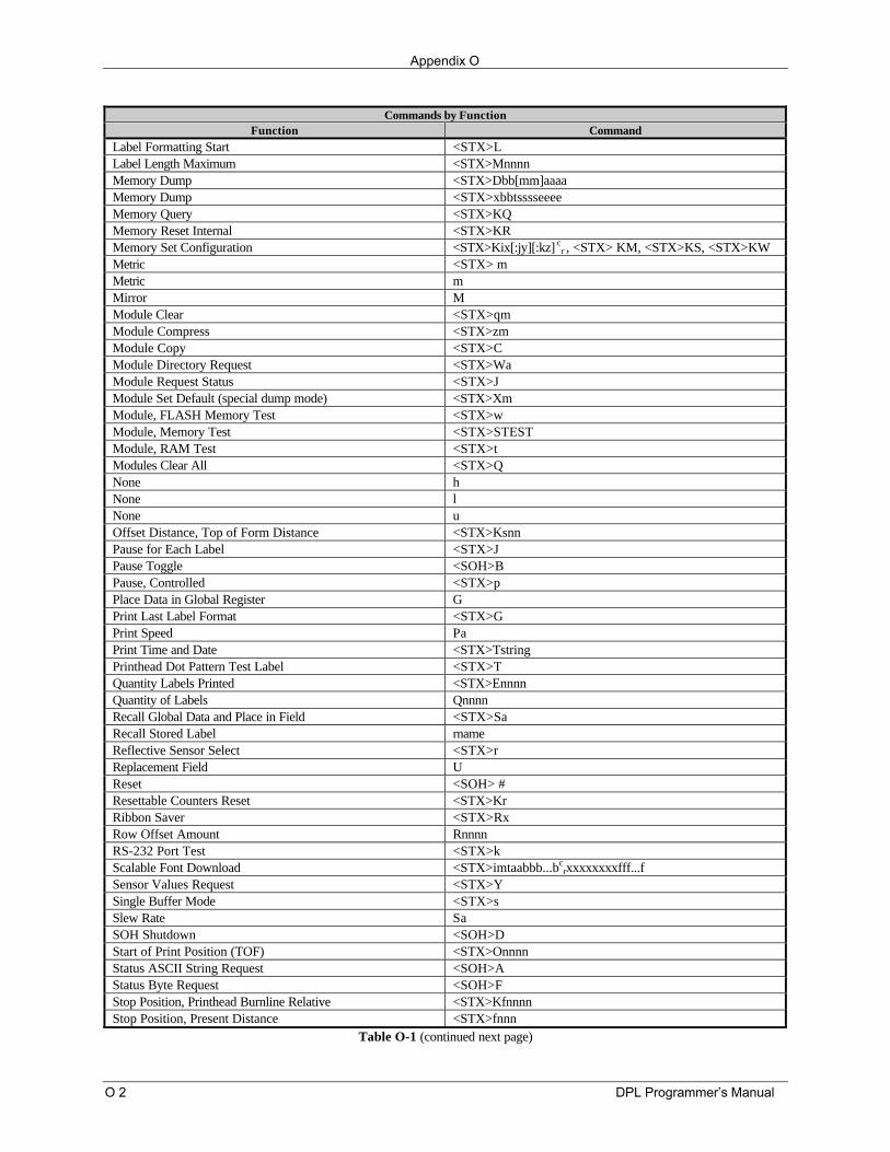
Appendix O
O 2 DPL Programmer’s Manual
Commands by FunctionFunction Command
Label Formatting Start <STX>LLabel Length Maximum <STX>MnnnnMemory Dump <STX>Dbb[mm]aaaaMemory Dump <STX>xbbtsssseeeeMemory Query <STX>KQMemory Reset Internal <STX>KRMemory Set Configuration <STX>Kix[:jy][:kz] c
r , <STX> KM, <STX>KS, <STX>KWMetric <STX> mMetric mMirror MModule Clear <STX>qmModule Compress <STX>zmModule Copy <STX>CModule Directory Request <STX>WaModule Request Status <STX>JModule Set Default (special dump mode) <STX>XmModule, FLASH Memory Test <STX>wModule, Memory Test <STX>STESTModule, RAM Test <STX>tModules Clear All <STX>QNone hNone lNone uOffset Distance, Top of Form Distance <STX>KsnnPause for Each Label <STX>JPause Toggle <SOH>BPause, Controlled <STX>pPlace Data in Global Register GPrint Last Label Format <STX>GPrint Speed PaPrint Time and Date <STX>TstringPrinthead Dot Pattern Test Label <STX>TQuantity Labels Printed <STX>EnnnnQuantity of Labels QnnnnRecall Global Data and Place in Field <STX>SaRecall Stored Label rnameReflective Sensor Select <STX>rReplacement Field UReset <SOH> #Resettable Counters Reset <STX>KrRibbon Saver <STX>RxRow Offset Amount RnnnnRS-232 Port Test <STX>kScalable Font Download <STX>imtaabbb...bc
rxxxxxxxxfff...fSensor Values Request <STX>YSingle Buffer Mode <STX>sSlew Rate SaSOH Shutdown <SOH>DStart of Print Position (TOF) <STX>OnnnnStatus ASCII String Request <SOH>AStatus Byte Request <SOH>FStop Position, Printhead Burnline Relative <STX>KfnnnnStop Position, Present Distance <STX>fnnn
Table O-1 (continued next page)
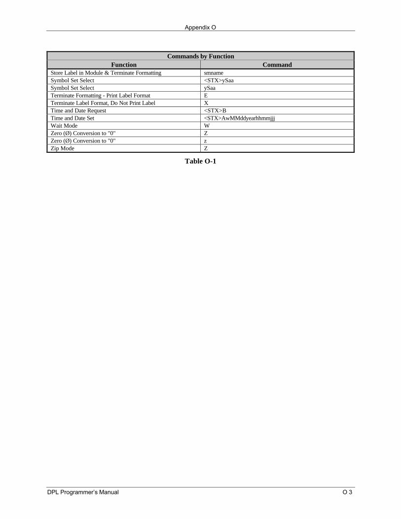
Appendix O
DPL Programmer’s Manual O 3
Commands by FunctionFunction Command
Store Label in Module & Terminate Formatting smnameSymbol Set Select <STX>ySaaSymbol Set Select ySaaTerminate Formatting - Print Label Format ETerminate Label Format, Do Not Print Label XTime and Date Request <STX>BTime and Date Set <STX>AwMMddyearhhmmjjjWait Mode WZero (Ø) Conversion to "0" ZZero (Ø) Conversion to "0" zZip Mode Z
Table O-1
Appendix O
O 4 DPL Programmer’s Manual
DPL Programmer’s Manual P 1
Appendix P
Image Loading
The printer will accept four types of image files: .BMP, .IMG, .PCX and a special Datamax 7-bit ASCIIfile (as defined in this section). Using the Datamax 7-bit ASCII format will require at least twice as muchdata transmission time as the other formats, (see <STX>I). The Datamax ASCII image file format ismade up of a set of records with identical formats, each representing a dot row of the image. The last ofthese records is followed by a terminator.
Dot-row record••••
Dot-row recordTerminator
Each dot-row record has the following format:
Syntax: 80nndd...d<CR>
Where: nn - Number character pairs in dd...d, represented in ASCII hex.
dd…d - Dot data, character pairs, ASCII hex, 00-FF
Duplicate records may be encoded using a repeat data record, following the data record that needsduplicating. The repeat data record format is:
Syntax: 0000FFnn<CR>
Where: nn - Is the number of duplicates, ASCII hex, 00-FF.
The terminator, last record, at the image download is: FFFF<CR>
Appendix P
P 2 DPL Programmer’s Manual
^BqA(CR)^BIAAFLOGO(CR)
8030FFFFFFFFFFFFFFFFFFFFFFFFFFFFFFFFFFFFFFFFFFFFFFFFFFFFFFFFFFFFFFFFFFFFFFFFFFFFFFFFFFFFFFFFFFFF0000(CR)
8030FFFFFFFFFFFFFFFFFFFFFFFFFFFFFFFFFFFFFFFFFFFFFFFFFFFFFFFFFFFFFFFFFFFFFFFFFFFFFFFFFFFFFFFFFFFF0000(CR)
8030FFFFFFFFFFFFFFFFFFFFFFFFFFFFFFFFFFFFFFFFFFFFFFFFFFFFFFFFFFFFFFFFFFFFFFFFFFFFFFFFFFFFFFFFFFFF0000(CR)
8030FFFFFFFFFFFFFFFFFFFFFFFFFFFFFFFFFFFFFFFFFFFFFFFFFFFFFFFFFFFFFFFFFFFFFFFFFFFFFFFFFFFFFFFFFFFF0000(CR)
8030FFFFFFFFFFFFFFFFFFFFFFFFFFFFFFFFFFFFFFFFFFFFFFFFFFFFFFFFFFFFFFFFFFFFFFFFFFFFFFFFFFFFFFFFFFFF0000(CR)
8030FFFFFFFFFFFFFFFFFFFFFFFFFFFFFFFFFFFFFFFFFFFFFFFFFFFFFFFFFFFFFFFFFFFFFFFFFFFFFFFFFFFFFFFFFFFF0000(CR)
8030FFFFFFFFFFFFFFFFFFFFFFFFFFFFFFFFFFFFFFFFFFFFFFFFFFFFFFFFFFFFFFFFFFFFFFFFFFFFFFFFFFFFFFFFFFFF0000(CR)
8030FFC00000007FFC0003FFFFC001FC0001FC0003FFFFC0018000FFC001FF8000C0003FFFFE000000FFFFE0001FFFFF0000(CR)
8030FFC00000000FFC0003FFFFC001FC0001FC0003FFFFC0018000FFC001FF800040001FFFFE0000007FFFC0001FFFFF0000(CR)
8030FFC000000003FC0001FFFFC001FC0001FC0001FFFFC0018000FFC001FF800040001FFFFE0000003FFFC0001FFFFF0000(CR)
8030FFC000000000FC0001FFFFC001FE0001FE0001FFFFC00180007FC000FF800060001FFFFE0000003FFFC0003FFFFF0000(CR)
8030FFE0000000007E0001FFFFC001FE0001FE0001FFFFC00180007FC000FFC00060000FFFFE0000001FFFC0003FFFFF0000(CR)
8030FFE0000000003E0000FFFFC001FE0000FE0000FFFFC00180007FC0007FC00020000FFFFE0000001FFF80003FFFFF0000(CR)
8030FFE0000000001E0000FFFFC001FE0000FF0000FFFFC001C0007FC0007FC00030000FFFFE0010000FFF80003FFFFF0000(CR)
8030FFE0000000000F0000FFFFC001FE0000FF0000FFFFC001C0007FC0007FC00030000FFFFE00180007FF80007FFFFF0000(CR)
8030FFE0000000000700007FFFC001FF0000FF80007FFFC001C0007FC0003FC000380007FFFE00180007FF80007FFFFF0000(CR)
8030FFF0000000000380007FFFC001FF0000FF80007FFFC001C0003FC0003FE000380007FFFE001C0003FF80007FFFFF0000(CR)
8030FFF0000000000380007FFFC001FF0000FF80007FFFC001C0003FC0003FE000380007FFFE001E0003FF80007FFFFF0000(CR)
8030FFF0000000000180003FFFC001FF00007FC0003FFFC001C0003FC0001FE0001C0003FFFE001E0001FF0000FFFFFF0000(CR)
8030FFF00000000001C0003FFFC001FF00007FC0003FFFC001E0003FC0001FE0001C0003FFFE001F0000FF0000FFFFFF0000(CR)
8030FFF00007C00000C0003FFFC001FF00007FE0003FFFC001E0003FC0000FF0001E0003FFFE001F0000FF0000FFFFFF0000(CR)
8030FFF80007F80000E0001FFFC001FF80007FE0001FFFC001E0003FC0000FF0001E0001FFFE001F80007F0000FFFFFF0000(CR)
8030FFF80007FC0000E00000000001FF80007FE00000000001E0001FC0000FF0001E00000000001FC0007F0000FFFFFF0000(CR)
8030FFF80007FE0000600000000001FF80003FF00000000001E0001FC00007F0000F00000000001FC0003F0001FFFFFF0000(CR)
8030FFF80003FF0000700000000001FF80003FF00000000001F0001FC00007F0000F00000000001FE0001E0001FFFFFF0000(CR)
8030FFF80003FF0000700000000001FF80003FF00000000001F0001FC00007F8000F00000000001FE0001E0001FFFFFF0000(CR)
8030FFFC0001FFC0003C0000000001FFE0001FFE0000000001F8000FC00000FC0007E0000000001FFE00000003FFFFFF0000(CR)
8030FFFE0001FFC0001E0000000001FFE0001FFE0000000001F8000FC00000FC0007E0000000001FFF00000003FFFFFF0000(CR)
8030FFFE0001FFC0001E0000000001FFE0001FFE0000000001F8000FC00000FC0007F0000000001FFF00000007FFFFFF0000(CR)
8030FFFE0000FFC0001F0000000001FFE0000FFF0000000001F8000FC000007C0003F0000000001FFF80000007FFFFFF0000(CR)
8030FFFE0000FFC0001F0000000001FFE0000FFF0000000001FC0007C000007E0003F0000000001FFF80000007FFFFFF0000(CR)
8030FFFE0000FFE0001F0001FFC001FFE0000FFF8001FFC001FC0007C000003E0003F8000FFE001FFFC0000007FFFFFF0000(CR)
8030FFFE0000FFE0000F8001FFC001FFF0000FFF8000FFC001FC0007C000003E0003F8000FFE001FFFE000000FFFFFFF0000(CR)
8030FFFF0000FFE0000F8000FFC001FFF0000FFF8000FFC001FC0007C000003E0003F8000FFE001FFFE000000FFFFFFF0000(CR)
8030FFFF0000FFE0000F8000FFC001FFF00007FFC000FFC001FC0007C000001F0001FC000FFE001FFFF000000FFFFFFF0000(CR)
8030FFFF00007FE0000FC000FFC001FFF00007FFC0007FC001FE0007C002001F0001FC0007FE001FFFF000000FFFFFFF0000(CR)
8030FFFF00007FF0000FC0007FC001FFF00007FFE0007FC001FE0003C002001F0001FE0007FE001FFFF800000FFFFFFF0000(CR)
8030FFFF00007FF0000FE0007FC001FFF80007FFE0007FC001FE0003C003000F0001FE0007FE001FFFFC00001FFFFFFF0000(CR)
Appendix O
DPL Programmer’s Manual O 3
8030FFFF80007FF00007E0007FC001FFF80007FFE0003FC001FE0003C003000F0001FE0003FE001FFFFC00001FFFFFFF0000(CR)
8030FFFF80007FF00007E0003FC001FFF80003FFF0003FC001FE0003C00300078001FF0003FE001FFFFE00001FFFFFFF0000(CR)
8030FFFF80003FF00007F0003FC001FFF80003FFF0003FC001FE0003C00380078000FF0003FE001FFFFE00001FFFFFFF0000(CR)
8030FFFF80003FF80007F0003FC001FFF80003FFF0001FC001FF0003C00380078000FF8001FE001FFFFE00001FFFFFFF0000(CR)
8030FFFF80003FF80007F0001FC001FFF80003FFF8001FC001FF0001C003C0038000FF8001FE001FFFFE00001FFFFFFF0000(CR)
8030FFFFFFC0000000007FFC000001F80000000000FC000001FFF0000003FFE0000007FFC000001FFFC0003F80007FFF0000(CR)
8030FFFFFFE000000000FFFC000001F80000000000FE000001FFF8000003FFE0000007FFE000001FFFC0003FC0003FFF0000(CR)
8030FFFFFFF000000000FFFE000001F80000000000FE000001FFF8000003FFF0000007FFE000001FFFC0003FC0003FFF0000(CR)
8030FFFFFFFC00000000FFFE000001FC0000000000FE000001FFF8000003FFF0000007FFE000001FFFC0003FE0001FFF0000(CR)
8030FFFFFFFE00000000FFFE000001FC00000000007F000001FFF8000003FFF0000007FFF000001FFFC0003FE0001FFF0000(CR)
8030FFFFFFFF00000001FFFF000001FC00000000007F000001FFF8000003FFF8000007FFF000001FFF80003FF0000FFF0000(CR)
8030FFFFFFFFC0000001FFFF000001FC00000000007F000001FFF8000003FFF8000003FFF800001FFF80007FF0000FFF0000(CR)
8030FFFFFFFFE0000003FFFF800001FC00000000007F800001FFFC000003FFF8000003FFF800001FFF80007FF80007FF0000(CR)
8030FFFFFFFFF0000007FFFF800001FC00000000007F800001FFFC000003FFFC000003FFF800001FFF80007FF80007FF0000(CR)
8030FFFFFFFFF800000FFFFF800001FE00000000003FC00001FFFC000003FFFC000003FFFC00001FFF00007FFC0003FF0000(CR)
8030FFFFFFFFFE00001FFFFFC00001FE00000000003FC00001FFFC000003FFFE000003FFFC00001FFF00007FFC0003FF0000(CR)
8030FFFFFFFFFF00007FFFFFC00001FE00000000003FC00001FFFC000003FFFE000003FFFE00001FFF00007FFE0001FF0000(CR)
8030FFFFFFFFFF8003FFFFFFC00001FE00000000003FE00001FFFC000003FFFF000003FFFE00001FFF00007FFE0001FF0000(CR)
8030FFFFFFFFFFFFFFFFFFFFFFFFFFFFFFFFFFFFFFFFFFFFFFFFFFFFFFFFFFFFFFFFFFFFFFFFFFFFFFFFFFFFFFFFFFFF0000(CR)
8030FFFFFFFFFFFFFFFFFFFFFFFFFFFFFFFFFFFFFFFFFFFFFFFFFFFFFFFFFFFFFFFFFFFFFFFFFFFFFFFFFFFFFFFFFFFF0000(CR)
8030FFFFFFFFFFFFFFFFFFFFFFFFFFFFFFFFFFFFFFFFFFFFFFFFFFFFFFFFFFFFFFFFFFFFFFFFFFFFFFFFFFFFFFFFFFFF0000(CR)
8030FFFFFFFFFFFFFFFFFFFFFFFFFFFFFFFFFFFFFFFFFFFFFFFFFFFFFFFFFFFFFFFFFFFFFFFFFFFFFFFFFFFFFFFFFFFF0000(CR)
8030FFFFFFFFFFFFFFFFFFFFFFFFFFFFFFFFFFFFFFFFFFFFFFFFFFFFFFFFFFFFFFFFFFFFFFFFFFFFFFFFFFFFFFFFFFFF0000(CR)
8030FFFFFFFFFFFFFFFFFFFFFFFFFFFFFFFFFFFFFFFFFFFFFFFFFFFFFFFFFFFFFFFFFFFFFFFFFFFFFFFFFFFFFFFFFFFF0000(CR)
8030FFFFFFFFFFFFFFFFFFFFFFFFFFFFFFFFFFFFFFFFFFFFFFFFFFFFFFFFFFFFFFFFFFFFFFFFFFFFFFFFFFFFFFFFFFFF0000(CR)
FFFF(CR)^BL(CR)1Y1100000000000LOGO(CR)E(CR)
Figure P-1 Sample Datamax 7-bit ASCII File Image
Figure P-2 Sample Label

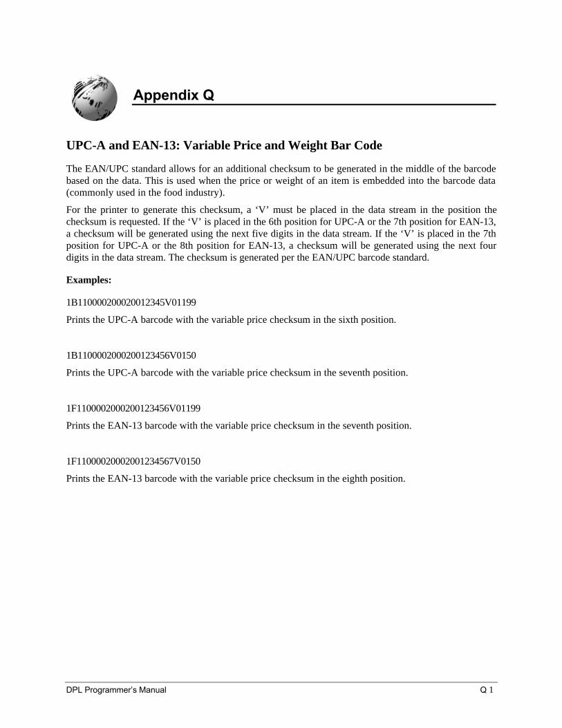
DPL Programmer’s Manual Q 1
Appendix Q
UPC-A and EAN-13: Variable Price and Weight Bar Code
The EAN/UPC standard allows for an additional checksum to be generated in the middle of the barcodebased on the data. This is used when the price or weight of an item is embedded into the barcode data(commonly used in the food industry).
For the printer to generate this checksum, a ‘V’ must be placed in the data stream in the position thechecksum is requested. If the ‘V’ is placed in the 6th position for UPC-A or the 7th position for EAN-13,a checksum will be generated using the next five digits in the data stream. If the ‘V’ is placed in the 7thposition for UPC-A or the 8th position for EAN-13, a checksum will be generated using the next fourdigits in the data stream. The checksum is generated per the EAN/UPC barcode standard.
Examples:
1B110000200020012345V01199
Prints the UPC-A barcode with the variable price checksum in the sixth position.
1B1100002000200123456V0150
Prints the UPC-A barcode with the variable price checksum in the seventh position.
1F1100002000200123456V01199
Prints the EAN-13 barcode with the variable price checksum in the seventh position.
1F11000020002001234567V0150
Prints the EAN-13 barcode with the variable price checksum in the eighth position.

Appendix Q
Q 2 DPL Programmer’s Manual
DPL Programmer’s Manual R 1
Appendix R
Barcode Symbology Information Sources
AIM International, Inc.11860 Sunrise Valley Drive, Suite 101Reston, VA 22091 USATel: 703-391-7621 Fax: 703-391-7624
Automotive Industry Action Group26200 Lahser RoadSuite 200Southfield, MI 48034 USATel: 313-358-3570 Fax: 313-358-3253
AIM JAPANAios Gotanda Bldg. 6F1-10-7 HigashigotandaShinagawa-ku Tokyo 141 JapanTel: 03-3440-9085 Fax: 03-3440-9086
Computing Technology Industry Association450 E. 22 Street Suite 230Lombard, IL 60148-6158 USATel: 630 268-1818 Fax: 630 278-1384
AIM EUROPEThe Old VicarageHaley Hill, Halifax HX3 6DRWest Yorkshire, EnglandTel: 44-1422-359161 Fax: 44-1422-3556904
Health Industry Business Communications CouncilPO Box 53528Phoenix, AZ 85018 USATel 602-318-1091
AIM UKThe Old VicarageHaley Hill, Halifax HX3 6DRUnited KingdomTel: 44-1422-359161 Fax: 44-1422-355604
International Article Numbering Association(EAN)Rue Royal 29B-1000 BruxellesBelgiumTel: 32-22-187674 Fax: 32-22-187585
AIM USA634 Alpha DrivePittsburgh, PA 15238-2802 USATel: 412-963-8588 Fax: 412-963-8753
Uniform Code Council, Inc. (UCC)8163 Old Yankee Rd. Suite JDayton, OH 45458 USATel: 513-435-3870 Fax: 513-435-4749
American National Standards Institute (ANSI)11 West 42nd StreetNew York, New York 10036 USATel: 212-642-4900 Fax: 212-398-0023
U.S. Government Printing Office732 North Capitol Street NWWashington, DC 20401 USATel: 202-512-1991 Fax: 202-512-1293

Appendix R
R 2 DPL Programmer’s Manual