Embed Size (px)
Citation preview
DPL Programmer’s Manual
Datamax InternationalHerbert House
12 Elizabeth Way, PinnaclesHarlow, Essex CM19 5FE UK
Phone: +44 1279 772200Fax: +44 1279 424448
Asia-Pacific19 Loyang Way
#01-01 CILC BuildingSingapore 508724
Phone: +65 542-2611Fax: +65 542-3611
Corporate Headquarters4501 Parkway Commerce Blvd.
Orlando, Fl 32808Phone: 407-578-8007
Fax: 407-578-8377

CG Times, based upon Times New Roman under license from the Monotype CorporationCG Triumvirate is a trademark of the AGFA CorporationMacintosh is a trademark of the Apple Corporation.PCL-4 and HP Laser JetII are trademarks of the Hewlett Packard CorporationWindows is a trademark of the Microsoft Corporation
Information in this manual is subject to change without notice and does not represent a commitment onthe part of Datamax Corporation. No part of this manual may be reproduced or transmitted in any form orby any means, for any purpose other than the purchaser’s personal use, without the expressed writtenpermission of Datamax Corporation.
© 2002 by Datamax Corporation
Part Number: 88-2302-01
Revision: B

i
Table of Contents
Preface ..........................................................................................................................1
Who Should Use This Manual .................................................................................................................. 1
Scope of This Manual ............................................................................................................................... 1
General Conventions ................................................................................................................................ 2
Computer Entry and Display Conventions ................................................................................................ 2
Getting to Know the Printer ....................................................................................................................... 3
Control Codes.............................................................................................................13
Introduction ............................................................................................................................................. 13
ttention Getters........................................................................................................................................ 13
Immediate Commands ...............................................................................................15
Introduction ............................................................................................................................................. 15
SOH # Reset ................................................................................................................................... 15
SOH A Send ASCII Status String .................................................................................................... 15
SOH B Toggle Pause....................................................................................................................... 16
SOH C Stop/Cancel ......................................................................................................................... 16
SOH D SOH Shutdown .................................................................................................................... 16
SOH E Send Batch Quantity............................................................................................................ 17
SOH F Send Status Byte ................................................................................................................. 17
SOH U Update System Database with Current Database............................................................... 17
System-Level Commands ..........................................................................................19
Introduction ............................................................................................................................................. 19
STX A Set Time and Date ............................................................................................................... 19
STX a Enable Feedback Characters .............................................................................................. 20
STX B Get Printer Time and Date Information................................................................................ 20
STX c Set Continuous Paper Length.............................................................................................. 21
STX d Set Double Buffer Mode....................................................................................................... 21
STX E Set Quantity For Stored Label.............................................................................................. 21
ii
STX e Select Edge Sensor ............................................................................................................. 22
STX F Form Feed ........................................................................................................................... 22
STX f Set Form Stop Position (Backfeed Command).................................................................... 22
STX G Print Last Label Format........................................................................................................ 23
STX I Image Downloading ............................................................................................................. 23
STX i Scalable Font Downloading ................................................................................................. 24
STX J Set Pause for Each Label .................................................................................................... 24
STX k Test RS-232 Port ................................................................................................................. 24
STX L Enter Label-Formatting Command Mode ............................................................................ 25
STX M Set Maximum Label Length ................................................................................................. 25
STX m Set Metric Mode................................................................................................................... 25
STX n Set Imperial (Inches) Mode.................................................................................................. 25
STX O Set Start of Print Position..................................................................................................... 26
STX o Cycle Cutter ......................................................................................................................... 26
STX P Character (Hex) Dump Mode............................................................................................... 26
STX p Controlled Pause ................................................................................................................. 26
STX Q Clear All Modules................................................................................................................. 27
STX q Clear Module........................................................................................................................ 27
STX r Select Reflective Sensor...................................................................................................... 27
STX S Set Feed Speed ................................................................................................................... 27
STX s Set Single Buffer Mode ........................................................................................................ 28
STX T Print Dot Pattern Label......................................................................................................... 28
STX t Test DRAM Memory Module................................................................................................ 28
STX U Label Format String Replacement Field .............................................................................. 29
STX V Software Switch Settings ..................................................................................................... 30
STX v Request Firmware Version .................................................................................................. 30
STX W Request Memory Module Information.................................................................................. 31
STX w Test Flash Memory Module ................................................................................................. 32
STX X Set Default Module .............................................................................................................. 32
iii
STX x Delete File from Module....................................................................................................... 33
STX Y Output Sensor Values.......................................................................................................... 33
STX y Select Font Symbol Set........................................................................................................ 34
STX Z Print Configuration and Dot Pattern Labels ......................................................................... 34
STX z Pack Module ........................................................................................................................ 34
Extended System Commands ...................................................................................35
Introduction ............................................................................................................................................. 35
STX K Memory Configuration.......................................................................................................... 35
STX Kb Backfeed Time Delay .......................................................................................................... 36
STX KC Get Configuration................................................................................................................. 37
STX Kc Set Configuration ................................................................................................................. 37
STX KD Database Configuration....................................................................................................... 41
STX KE Character Encoding............................................................................................................. 42
STX Kf Set Present Distance........................................................................................................... 44
STX KQ Query Memory Configuration............................................................................................... 44
STX KR Reset Memory Configuration............................................................................................... 45
STX Kr Reset Resettable Counter ................................................................................................... 45
STX KS Memory Configuration, Scalable Font Cache...................................................................... 45
STX KW Memory Configuration, Printable Label Width ..................................................................... 45
Label-Formatting Commands....................................................................................47
Introduction ............................................................................................................................................. 47
: Set Cut By Amount .............................................................................................................. 47
A Set Format Attribute ............................................................................................................ 48
C Set Column Offset Amount.................................................................................................. 49
c Set Cut By Amount .............................................................................................................. 49
D Set Dot Size Width and Height ............................................................................................ 50
E Terminate Label-Formatting Mode and Print....................................................................... 50
F Font Attributes ..................................................................................................................... 51
iv
f Set Present Speed............................................................................................................... 52
G Place Data in Global Register.............................................................................................. 52
H Select Heat Setting .............................................................................................................. 53
M Select Mirror Mode .............................................................................................................. 53
m Set Metric Mode................................................................................................................... 54
n Set Imperial (Inch) Mode ..................................................................................................... 54
P Set Print Speed.................................................................................................................... 54
p Set Backfeed Speed............................................................................................................ 55
Q Set Print Quantity................................................................................................................. 55
R Set Row Offset Amount ....................................................................................................... 56
r Recall Stored Label Format................................................................................................. 56
S Set Slew Speed ................................................................................................................... 57
s Store Label Format In Module ............................................................................................. 57
T Set Field Data Line Terminator............................................................................................ 58
U Mark Previous Field as a String Replacement Field............................................................ 58
X Terminate Label-Formatting Mode without Printing............................................................. 59
y Select Font Symbol Set ....................................................................................................... 59
z Zero (Ø) Conversion to “0” .................................................................................................. 60
+ (>) Make Last Field Entered Increment Numeric (Alphanumeric)............................................. 60
- (<) Make Last Field Entered Decrement Numeric (Alphanumeric)........................................... 61
^ Set Count by Amount .......................................................................................................... 62
Special Label-Formatting Commands .................................................................................................... 62
STX S Recall Global Data And Place In Field ................................................................................ 63
STX T Print Time and Date ............................................................................................................ 63
Font Loading Commands ..........................................................................................65
Introduction ............................................................................................................................................. 65
*c###D Assign Font ID Number....................................................................................................... 65
)s###W Font Descriptor ................................................................................................................... 65
*c###E Character Code................................................................................................................... 66
v
(s#W Character Download Data................................................................................................... 66
Generating Label Formats .........................................................................................67
Introduction ............................................................................................................................................. 67
Format Record Commands .................................................................................................................... 67
Generating Records................................................................................................................................ 68
The Structure of a Record....................................................................................................................... 68
Record Structure Types .......................................................................................................................... 71
Appendix A..................................................................................................................79
ASCII Control Chart ................................................................................................................................ 79
Appendix B..................................................................................................................81
Sample Programs ................................................................................................................................... 81
VB Application interfacing via Windows Driver ....................................................................................... 87
Appendix C..................................................................................................................93
Available Font Sizes, Referencing and Samples .................................................................................... 93
Appendix D..................................................................................................................99
Error Codes............................................................................................................................................. 99
Appendix E................................................................................................................101
Single-Byte Symbol Sets....................................................................................................................... 101
Appendix F ................................................................................................................111
Bar Code Summary Data...................................................................................................................... 111
Appendix G ...............................................................................................................113
Bar Code Details ................................................................................................................................... 113
Appendix H................................................................................................................141
Font Mapping: Single-Byte and Double-Byte Characters...................................................................... 141
vi
Appendix I .................................................................................................................143
Symbol Sets and Character Maps ........................................................................................................ 143
Double-Byte Symbols, Chinese, Kanji and Korean............................................................................... 145
Appendix J ................................................................................................................147
Module Identifiers, Field Limits, Print Resolutions, & Column Values .................................................. 147
Appendix K................................................................................................................149
Speed Ranges and Defaults ................................................................................................................. 149
Appendix L ................................................................................................................151
Commands by Function ........................................................................................................................ 151
Appendix M ...............................................................................................................153
Image Loading ...................................................................................................................................... 153
Appendix N................................................................................................................155
UPC-A and EAN-13: Variable Price and Weight Bar Code .................................................................. 155
Appendix O ...............................................................................................................157
International Language Print Capability (ILPC) Programming Examples ............................................. 157
Appendix P................................................................................................................165
Downloading Firmware ......................................................................................................................... 165
Appendix Q ...............................................................................................................167
Bar Code Symbology Information Sources........................................................................................... 167
Glossary ....................................................................................................................169
M-Class DPL Programmer’s Manual 1
Preface
Who Should Use This Manual
This manual is intended for programmers who wish to create their own label production software.Operators without programming experience may prefer to use a label-creation software package. Forprogramming information on models not covered in this document, a copy may be downloaded from ourweb site at http://www.datamaxcorp.com.
Scope of This Manual
This manual explains the Datamax Programming Language (DPL) and its related uses in the writing,loading and storing of programs for the control and production of label formats using the Datamax M-Class printers with Application (firmware) Versions 1.00 and above. This manual contains the followingchapters and appendices.
� PREFACE on page 1Contents, organization and conventions used in this manual
� CONTROL CODES on page 13Description of the attention-getter characters necessary for the printer to receive a commandsequence, and available alternate characters and line terminators.
� IMMEDIATE COMMANDS on page 15Description of the commands, listed alphabetically, that perform status queries and printer controlcommands.
� SYSTEM-LEVEL COMMANDS on page 19Description of the commands, listed alphabetically, that control the printer and allow scalable fontand image downloads.
� EXTENDED SYSTEM COMMANDS on page 35Description of the commands, listed alphabetically, that control the printer.
� LABEL-FORMATTING COMMANDS on page 47Description of commands, listed alphabetically, that control the position of text and images on themedia, print or store, and end the formatting process.
� FONT-LOADING COMMANDS on page 65Description of commands, listed alphabetically, used when downloading font data in PCL-4compatible bit-maps.
Preface
2 M-Class DPL Programmer’s Manual
� GENERATING LABEL FORMATS on page 67Description of the structure of records, the different types, and their use in generating label formats.
� APPENDICIES A THROUGH Q on pages 79 through 167These contain details that cannot be ignored including various tables, programming examples,printer default values, and bar code symbology details. See the Table of Contents for specificcontent information.
� GLOSSARY on page 169Definitions of words, abbreviations, and acronyms used in this manual.
General Conventions
These are some of the conventions followed in this manual:
• On the header of each page, the name of the chapter.
• On the footer of each page, the page number and the title of the manual.
• Names of other manuals referenced are in Italics.
• Notes are added to bring your attention to important considerations, tips or helpful suggestions.
• Boldface is also used to bring your attention to important information.
• This manual refers to IBM-PC based keyboard command characters for access to the ASCIIcharacter set. Systems based on different formats (e.g., Apple’s Macintosh ) should use theappropriate keyboard command to access the desired ASCII character. See Appendix A for theASCII character set.
Computer Entry and Display Conventions
Command syntax and samples are formatted as follows:
• The Courier font in boldface indicates the DPL command syntax, and Italics are used to indicatethe command syntax parameters.
• Regular Courier font indicates sample commands, files and printer responses.
• Square brackets [ ] around something indicates that it is optional.
• <CR> is used to identify the line termination character. Other strings placed between < > in thismanual represent the character of the same ASCII name, and are single-byte hexadecimal values(e.g., <STX>, <CR>, and <0x0D> equal 02, 0D, and 0D, respectively).
• Hexidecimal values are often displayed in ‘C’ programming language conventions (e.g., 0x02 = 02hex, 0x41 = 41 hex, etc.)
Preface
M-Class DPL Programmer’s Manual 3
Getting to Know the Printer
The following highlights basic printer setup and control. For detailed information, including connections,features, media loading, and operating instructions refer to the Operator’s Manual.
� Connecting Power
� Note: When connecting the AC Power Cord, ensure that the Power On/Off Switch is in the ‘Off’ position.
1. Place the printer on a firm, level surface and ensure that thePower Switch is in the ‘Off’ position.
2. Connect the AC Power Cord into the receptacle on thePrinter, and then plug the cord into a properly groundedoutlet. (See the Operator’s Manual for the acceptablevoltage ranges.)
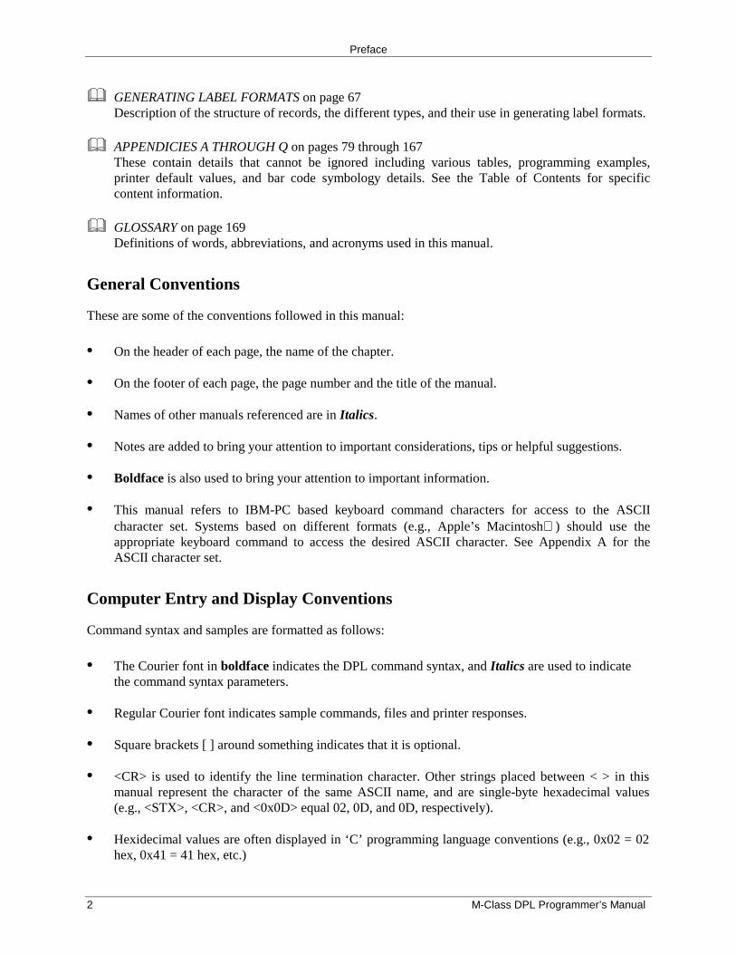
� Interfacing
The printer can be connected to a host via the USB, parallel, or serial interface port. The printer willautomatically connect to the first port that transmits valid data. (After this connection is made, the printermust be turned ‘Off’ and ‘On’, to change the interface selection).
USB: This interface is supported under Windows 95 and greater.Depending upon the operating system of your host computer,installation may differ slightly.
Parallel: This interface requires a Centronics IEEE 1284 cablewith a 36-pin male connector. Bi-directional mode is IEEE 1284Compliant, using forward and reverse channel communications.In this mode, data can be sent to the host provided it is alsoIEEE 1284 Compliant and has supporting software.
Serial: This interface supports RS-232C communications.Printer serial port settings are menu-selectable and must matchthe host computer’s serial port settings (see the Operator’sManual).
• Baud Rate (default = 9600 bps)• Word Length (default = 8 bits)
In addition to these settings, the interface cable must havespecific pin-outs for proper data exchange. The acceptable cablepin-outs, and cable part numbers are listed in the following table(contact your reseller for ordering information).
Preface
4 M-Class DPL Programmer’s Manual
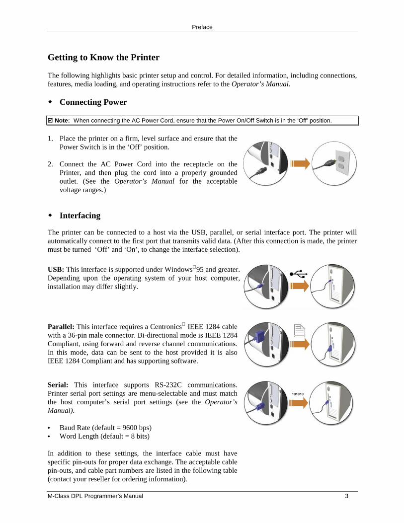
Serial Interface Cable Requirements
Part Number: 32-2300-01
Part Number: 32-2301-01
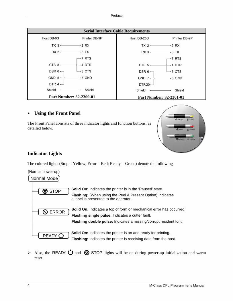
� Using the Front Panel
The Front Panel consists of three indicator lights and function buttons, asdetailed below.
Indicator Lights
The colored lights (Stop = Yellow; Error = Red; Ready = Green) denote the following
Normal Mode
(Normal power-up)
STOP Solid On: Indicates the printer is in the ‘Paused’ state.
Flashing: (When using the Peel & Present Option) Indicatesa label is presented to the operator.
Solid On: Indicates a top of form or mechanical error has occurred.
Flashing single pulse: Indicates a cutter fault.
Flashing double pulse: Indicates a missing/corrupt resident font.
Solid On: Indicates the printer is on and ready for printing.
Flashing: Indicates the printer is receiving data from the host.
ERROR
READY
� Also, the READY and STOP lights will be on during power-up initialization and warmreset.
Preface
M-Class DPL Programmer’s Manual 5
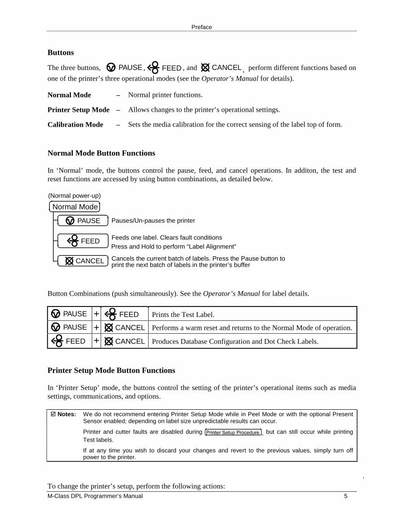
Buttons
The three buttons, PAUSE , FEED , and CANCEL , perform different functions based on
one of the printer’s three operational modes (see the Operator’s Manual for details).
Normal Mode – Normal printer functions.
Printer Setup Mode – Allows changes to the printer’s operational settings.
Calibration Mode – Sets the media calibration for the correct sensing of the label top of form.
Normal Mode Button Functions
In ‘Normal’ mode, the buttons control the pause, feed, and cancel operations. In additon, the test andreset functions are accessed by using button combinations, as detailed below.
Pauses/Un-pauses the printer
Feeds one label. Clears fault conditions
Cancels the current batch of labels. Press the Pause button toprint the next batch of labels in the printer’s buffer
Normal Mode
(Normal power-up)
CANCEL
PAUSE
FEEDPress and Hold to perform “Label Alignment”
Button Combinations (push simultaneously). See the Operator’s Manual for label details.
PAUSE + FEED Prints the Test Label.
PAUSE + CANCEL Performs a warm reset and returns to the Normal Mode of operation.
FEED + CANCEL Produces Database Configuration and Dot Check Labels.
Printer Setup Mode Button Functions
In ‘Printer Setup’ mode, the buttons control the setting of the printer’s operational items such as mediasettings, communications, and options.
� Notes: We do not recommend entering Printer Setup Mode while in Peel Mode or with the optional PresentSensor enabled; depending on label size unpredictable results can occur.
Printer and cutter faults are disabled during , but can still occur while printingTest labels.
If at any time you wish to discard your changes and revert to the previous values, simply turn offpower to the printer.
To change the printer’s setup, perform the following actions:
Preface
6 M-Class DPL Programmer’s Manual
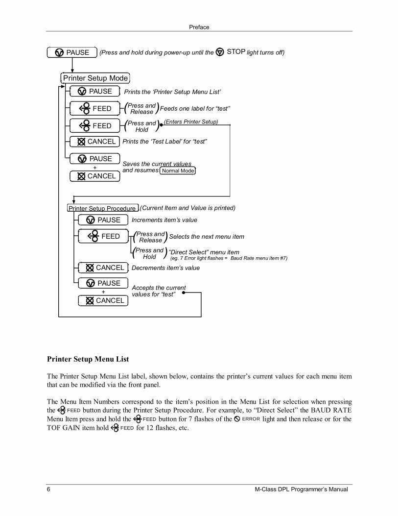
Printer Setup Procedure
Printer Setup Mode
Prints the ‘Printer Setup Menu List’
Prints the ‘Test Label’ for “test”
(Current Item and Value is printed)
Increments item’s value
Decrements item’s value
Accepts the currentvalues for “test”
PAUSE
PAUSE (Press and hold during power-up until the light turns off)STOP
PAUSE
Feeds one label for “test”Press andRelease( )FEED
FEED Press andHold( ) (Enters Printer Setup)
CANCEL
Saves the current valuesand resumes Normal Mode+
PAUSE
CANCEL
Press andRelease Selects the next menu item( )
Press andHold
”Direct Select” menu item(eg. 7 Error light flashes = Baud Rate menu item #7)
( )FEED
CANCEL
+PAUSE
CANCEL
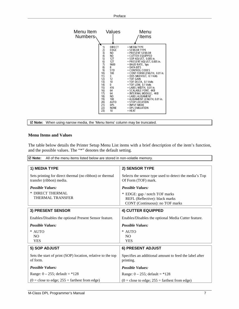
Printer Setup Menu List
The Printer Setup Menu List label, shown below, contains the printer’s current values for each menu itemthat can be modified via the front panel.
The Menu Item Numbers correspond to the item’s position in the Menu List for selection when pressingthe FEED button during the Printer Setup Procedure. For example, to “Direct Select” the BAUD RATEMenu Item press and hold the FEED button for 7 flashes of the ERROR light and then release or for theTOF GAIN item hold FEED for 12 flashes, etc.
Preface
M-Class DPL Programmer’s Manual 7
MenuItems
Values
1) DIRECT = MEDIA TYPE 2) EDGE = SENSOR TYPE 3) NO = PRESENT SENSOR 4) NO = CUTTER EQUIPPED 5) 127 = SOP ADJUST, 0.005 in. 6) 127 = PRESENT ADJUST, 0.005 in. 7) 9600 = BAUD RATE, bps 8) 8 = DATA BITS 9) STD = CONTROL CODES10) 100 = CONT FORM LENGTH, 0.01 in.11) 3 = OOS MAXVOLT, 0.1 Volts12) 12 = TOF GAIN13) 10 = TOF DELTA, 0.1 Volts14) 0 = TOF LOW, 0.1 Volts15) 416 = LABEL WIDTH, 0.01 in.16) 64 = SCALABLE FONT, 4KB17) 64 = INTERNAL MODULE, 4KB18) NO = LABEL ALIGNMENT19) 100 = ALIGNMENT LENGTH, 0.01 in.20) AUTO = STOP LOCATION21) DPL = INPUT MODE22) NONE = DPL EMULATION23) 10 = HEAT
Menu ItemNumbers
� Note: When using narrow media, the ‘Menu Items’ column may be truncated.
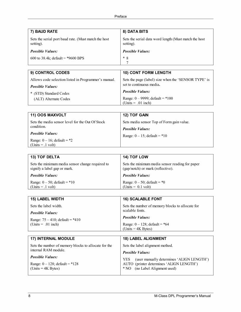
Menu Items and Values
The table below details the Printer Setup Menu List items with a brief description of the item’s function,and the possible values. The “*” denotes the default setting.
� Note: All of the menu items listed below are stored in non-volatile memory.
1) MEDIA TYPE
Sets printing for direct thermal (no ribbon) or thermaltransfer (ribbon) media.
Possible Values:* DIRECT THERMAL
THERMAL TRANSFER
2) SENSOR TYPE
Selects the sensor type used to detect the media’s TopOf Form (TOF) mark.
Possible Values:
* EDGE: gap / notch TOF marksREFL (Reflective): black marksCONT (Continuous): no TOF marks
3) PRESENT SENSOR
Enables/Disables the optional Present Sensor feature.
Possible Values:
* AUTONOYES
4) CUTTER EQUIPPED
Enables/Disables the optional Media Cutter feature.
Possible Values:
* AUTONOYES
5) SOP ADJUST
Sets the start of print (SOP) location, relative to the topof form.
Possible Values:
Range: 0 – 255; default = *128
(0 = close to edge; 255 = farthest from edge)
6) PRESENT ADJUST
Specifies an additional amount to feed the label afterprinting.
Possible Values:
Range: 0 – 255; default = *128
(0 = close to edge; 255 = farthest from edge)
Preface
8 M-Class DPL Programmer’s Manual
7) BAUD RATE
Sets the serial port baud rate. (Must match the hostsetting).
Possible Values:
600 to 38.4k; default = *9600 BPS
8) DATA BITS
Sets the serial data word length (Must match the hostsetting).
Possible Values:
* 87
9) CONTROL CODESAllows code selection listed in Programmer’s manual.
Possible Values:
* (STD) Standard Codes(ALT) Alternate Codes
10) CONT FORM LENGTHSets the page (label) size when the ‘SENSOR TYPE’ isset to continuous media.Possible Values:
Range: 0 – 9999; default = *100(Units = .01 inch)
11) OOS MAXVOLTSets the media sensor level for the Out Of Stockcondition.
Possible Values:
Range: 0 – 16; default = *2(Units = .1 volt)
12) TOF GAINSets media sensor Top of Form gain value.
Possible Values:
Range: 0 – 15; default = *10
13) TOF DELTASets the minimum media sensor change required tosignify a label gap or mark.
Possible Values:
Range: 0 – 50; default = *10(Units = .1 volt)
14) TOF LOWSets the minimum media sensor reading for paper(gap/notch) or mark (reflective).
Possible Values:
Range: 0 – 50; default = *0(Units = 0.1 volt)
15) LABEL WIDTHSets the label width.
Possible Values:
Range: 75 – 410; default = *410(Units = .01 inch)
16) SCALABLE FONTSets the number of memory blocks to allocate forscalable fonts.
Possible Values:
Range: 0 – 128; default = *64(Units = 4K Bytes)
17) INTERNAL MODULESets the number of memory blocks to allocate for theinternal RAM module.
Possible Values:
Range: 0 – 128; default = *128(Units = 4K Bytes)
18) LABEL ALIGNMENTSets the label alignment method.
Possible Values:
YES (user manually determines ‘ALIGN LENGTH’)AUTO (printer determines ‘ALIGN LENGTH’)* NO (no Label Alignment used)
Preface
M-Class DPL Programmer’s Manual 9
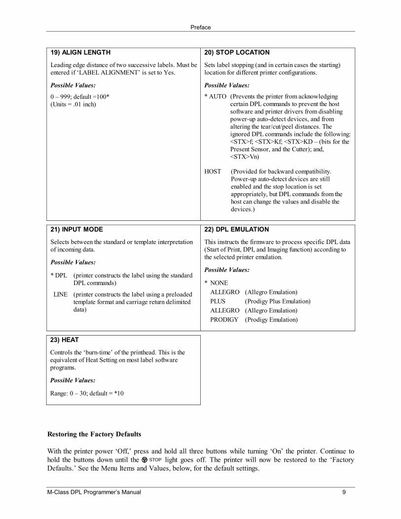
19) ALIGN LENGTH
Leading edge distance of two successive labels. Must beentered if ‘LABEL ALIGNMENT’ is set to Yes.
Possible Values:
0 – 999; default =100*(Units = .01 inch)
20) STOP LOCATION
Sets label stopping (and in certain cases the starting)location for different printer configurations.
Possible Values:
* AUTO (Prevents the printer from acknowledgingcertain DPL commands to prevent the hostsoftware and printer drivers from disablingpower-up auto-detect devices, and fromaltering the tear/cut/peel distances. Theignored DPL commands include the following:<STX>f; <STX>Kf; <STX>KD – (bits for thePresent Sensor, and the Cutter); and,<STX>Vn)
HOST (Provided for backward compatibility.Power-up auto-detect devices are stillenabled and the stop location is setappropriately, but DPL commands from thehost can change the values and disable thedevices.)
21) INPUT MODE
Selects between the standard or template interpretationof incoming data.
Possible Values:
* DPL (printer constructs the label using the standardDPL commands)
LINE (printer constructs the label using a preloadedtemplate format and carriage return delimiteddata)
22) DPL EMULATION
This instructs the firmware to process specific DPL data(Start of Print, DPI, and Imaging function) according tothe selected printer emulation.
Possible Values:
* NONEALLEGRO (Allegro Emulation)PLUS (Prodigy Plus Emulation)
ALLEGRO (Allegro Emulation) PRODIGY (Prodigy Emulation)
23) HEAT
Controls the ‘burn-time’ of the printhead. This is theequivalent of Heat Setting on most label softwareprograms.
Possible Values:
Range: 0 – 30; default = *10
Restoring the Factory Defaults
With the printer power ‘Off,’ press and hold all three buttons while turning ‘On’ the printer. Continue tohold the buttons down until the STOP light goes off. The printer will now be restored to the ‘FactoryDefaults.’ See the Menu Items and Values, below, for the default settings.
Preface
10 M-Class DPL Programmer’s Manual
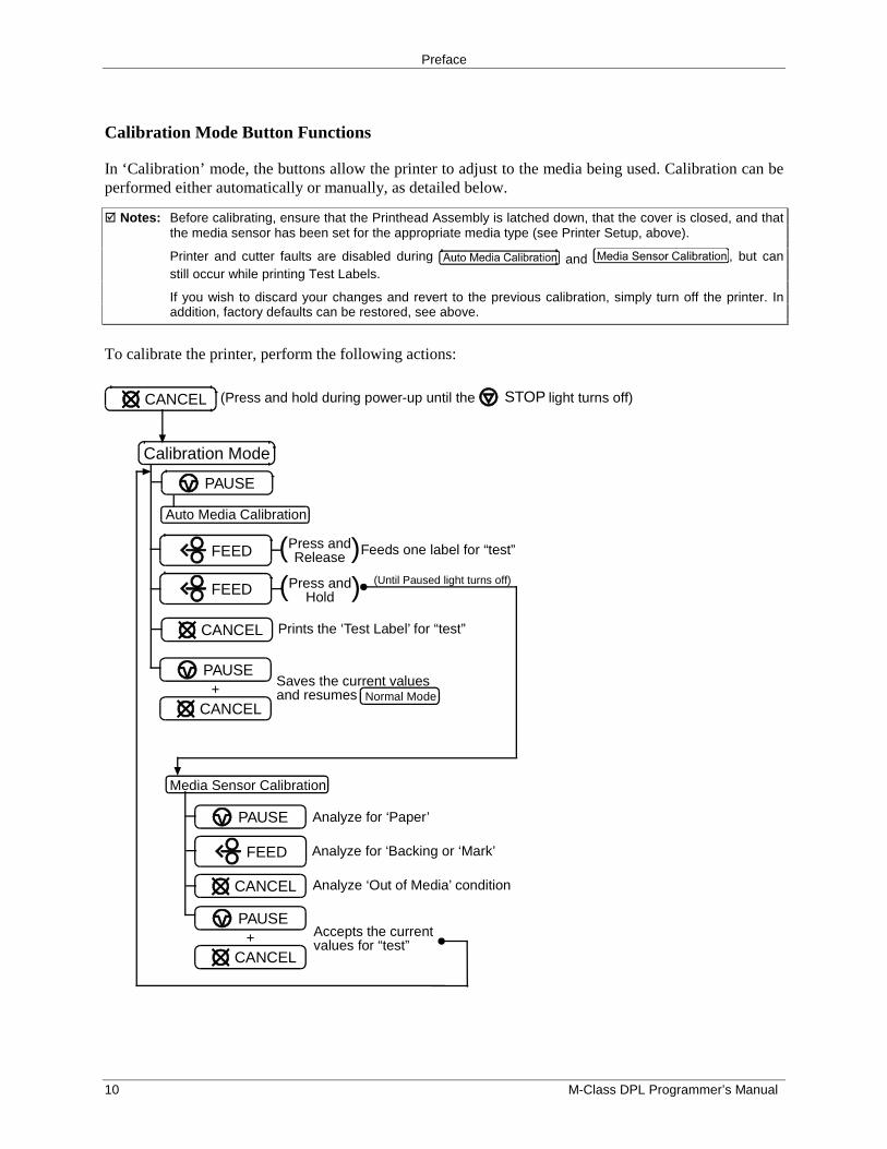
Calibration Mode Button Functions
In ‘Calibration’ mode, the buttons allow the printer to adjust to the media being used. Calibration can beperformed either automatically or manually, as detailed below.
� Notes: Before calibrating, ensure that the Printhead Assembly is latched down, that the cover is closed, and thatthe media sensor has been set for the appropriate media type (see Printer Setup, above).
Printer and cutter faults are disabled during and , but canstill occur while printing Test Labels.
If you wish to discard your changes and revert to the previous calibration, simply turn off the printer. Inaddition, factory defaults can be restored, see above.
To calibrate the printer, perform the following actions:
Auto Media Calibration
(Until Paused light turns off)
Calibration Mode
Analyze for ‘Paper’
Analyze for ‘Backing or ‘Mark’
Analyze ‘Out of Media’ condition
Prints the ‘Test Label’ for “test”
Media Sensor Calibration
(Press and hold during power-up until the light turns off)STOPCANCEL
PAUSE
Feeds one label for “test”Press andRelease( )FEED
FEED Press andHold( )
CANCEL
Saves the current valuesand resumes Normal Mode+
PAUSE
CANCEL
PAUSE
FEED
CANCEL
Accepts the currentvalues for “test”+
PAUSE
CANCEL
Preface
M-Class DPL Programmer’s Manual 11
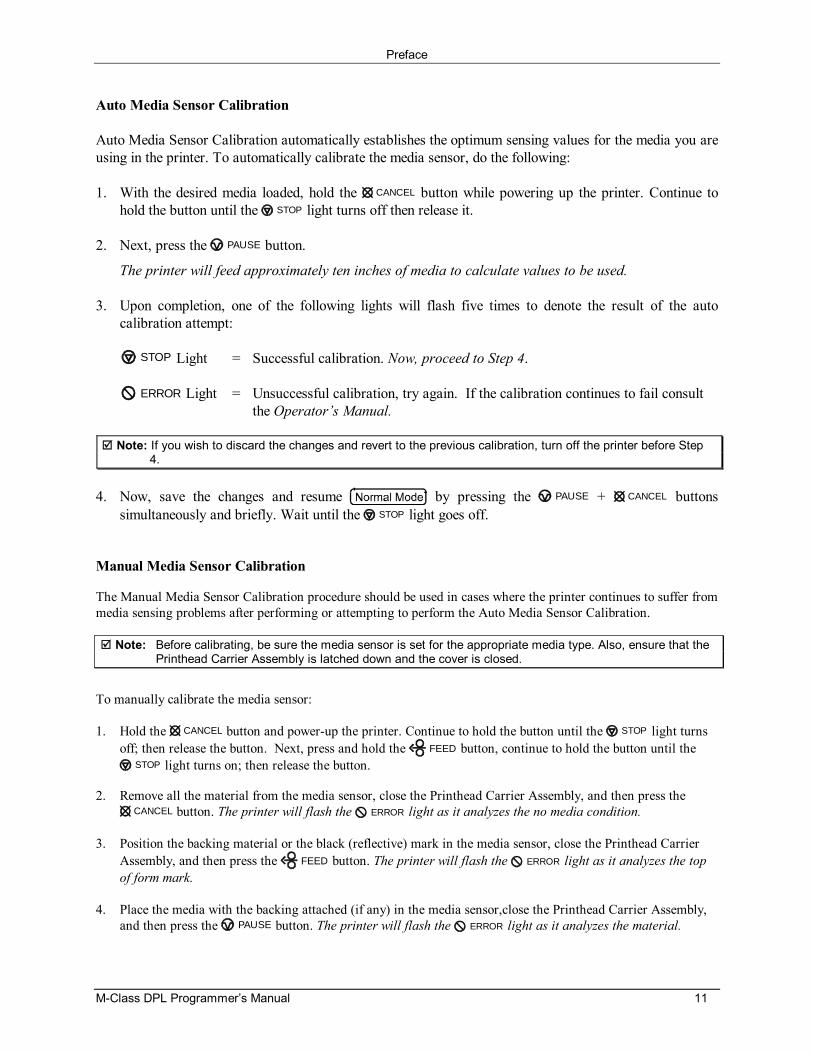
Auto Media Sensor Calibration
Auto Media Sensor Calibration automatically establishes the optimum sensing values for the media you areusing in the printer. To automatically calibrate the media sensor, do the following:
1. With the desired media loaded, hold the CANCEL button while powering up the printer. Continue tohold the button until the STOP light turns off then release it.
2. Next, press the PAUSE button.
The printer will feed approximately ten inches of media to calculate values to be used.
3. Upon completion, one of the following lights will flash five times to denote the result of the autocalibration attempt:
STOP Light = Successful calibration. Now, proceed to Step 4.
ERROR Light = Unsuccessful calibration, try again. If the calibration continues to fail consultthe Operator’s Manual.
Note: If you wish to discard the changes and revert to the previous calibration, turn off the printer before Step4.
4. Now, save the changes and resume by pressing the PAUSE + CANCEL buttonssimultaneously and briefly. Wait until the STOP light goes off.
Manual Media Sensor Calibration
The Manual Media Sensor Calibration procedure should be used in cases where the printer continues to suffer frommedia sensing problems after performing or attempting to perform the Auto Media Sensor Calibration.
Note: Before calibrating, be sure the media sensor is set for the appropriate media type. Also, ensure that thePrinthead Carrier Assembly is latched down and the cover is closed.
To manually calibrate the media sensor:
1. Hold the CANCEL button and power-up the printer. Continue to hold the button until the STOP light turnsoff; then release the button. Next, press and hold the FEED button, continue to hold the button until the
STOP light turns on; then release the button.
2. Remove all the material from the media sensor, close the Printhead Carrier Assembly, and then press theCANCEL button. The printer will flash the ERROR light as it analyzes the no media condition.
3. Position the backing material or the black (reflective) mark in the media sensor, close the Printhead CarrierAssembly, and then press the FEED button. The printer will flash the ERROR light as it analyzes the topof form mark.
4. Place the media with the backing attached (if any) in the media sensor,close the Printhead Carrier Assembly,and then press the PAUSE button. The printer will flash the ERROR light as it analyzes the material.
Preface
12 M-Class DPL Programmer’s Manual
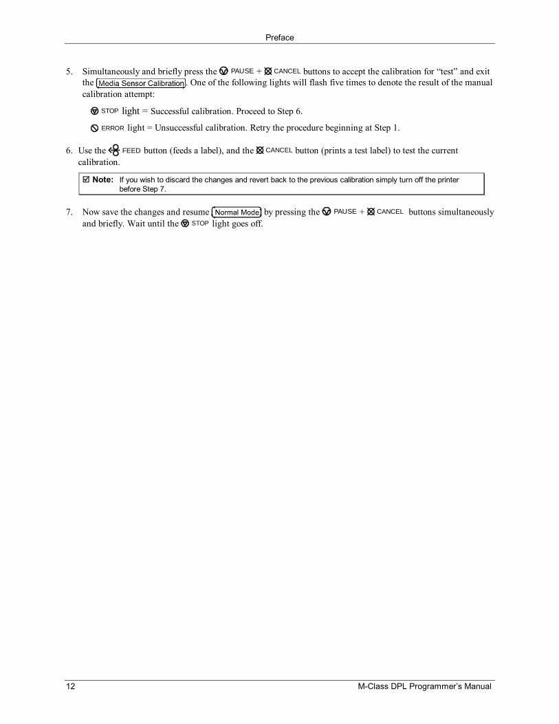
5. Simultaneously and briefly press the PAUSE + CANCEL buttons to accept the calibration for “test” and exitthe . One of the following lights will flash five times to denote the result of the manualcalibration attempt:
STOP light = Successful calibration. Proceed to Step 6.
ERROR light = Unsuccessful calibration. Retry the procedure beginning at Step 1.
6. Use the FEED button (feeds a label), and the CANCEL button (prints a test label) to test the currentcalibration.
Note: If you wish to discard the changes and revert back to the previous calibration simply turn off the printerbefore Step 7.
7. Now save the changes and resume by pressing the PAUSE + CANCEL buttons simultaneouslyand briefly. Wait until the STOP light goes off.
M-Class DPL Programmer’s Manual 13
Control Codes
IntroductionThe printer requires a special “attention getter” character in order to receive a command sequence,informing the printer that it is about to receive a command and the type of command it will be. ControlCommands, System-Level Commands, and Font-Loading Commands have their own unique attentiongetter, followed by a command character that directs printer action.
Attention GettersThe attention getters (e.g., “SOH”) are standard ASCII control labels that represent a one charactercontrol code (i.e., ^A or Ctrl A). Appendix A contains the entire ASCII Control Code Chart.
Attention Getter For: ASCII Character Decimal Value HEX ValueImmediate Commands SOH 1 01
System-Level Commands STX 2 02
Font-Loading Commands ESC 27 1B
Table 2-1: Control Code Listings
Alternate Control Code Modes
For systems unable to transmit certain control codes, Alternate Control Code Modes are available.Configuring the printer to operate in an Alternate Control Code Mode (selected via the Setup Menu orthe <STX>KD / <STX>Kc commands) requires the substitution of Standard Control Characters withAlternate Control Characters in what otherwise is a normal datastream.
Control Character Standard Alternate Alternate-2SOH 0x01 0x5E 0x5E
STX 0x02 0x7E 0x7E
CR 0x0D 0x0D 0x7C
ESC 0x1B 0x1B 0x1B
“Count By”[1] 0x5E 0x40 0x401 See Label-Formatting Commands, ^, set count by amount.
Table 2-2: Alternate Control Codes
� Note: Throughout this manual <SOH>, <STX>, <CR>, <ESC>, and ^, will be used to indicate the controlcodes. The actual values will depend on whether standard or alternate control codes are enabled forthe particular application.
Alternate Line Terminator
Alternate-2 Control Codes provide for substitution of the line terminator as well as the control characterslisted above. The line terminator <CR> (0x0D) is replaced by | (0x7C). The following is a sample labelformat datastream for a printer configured for Alternate-2 Control Codes:
~L|1911A10001000101234560|X|~UT01ABCDE|~G|
Control Codes
14 M-Class DPL Programmer’s Manual
M-Class DPL Programmer’s Manual 15
Immediate Commands
IntroductionWhen the printer receives an Immediate Command, its current operation will be momentarily interruptedto respond to the command. Immediate Commands may be issued before or after System-Levelcommands; however, they may not be issued among Label-Formatting Commands or during font orimage downloading. Immediate Commands consists of the following sequence:
1. Attention Getter, 0x01 or 0x5E, see Control Codes.
2. Command Character
SOH # Reset
This command resets the printer. Resetting the printer returns all settings to default and clears boththe communications and printing buffers. The command also clears DRAM memory.
Syntax: <SOH>#
Printer response: The printer will reset.T<XON> (The T may come after the <XON>).
SOH A Send ASCII Status String
This command allows the host computer to check the current printer status. The printer returns astring of eight characters, followed by a carriage return. Each character (see below) indicates anassociated condition, either true (Y) or false (N). Byte 1 is transmitted first. See <SOH>F.
Syntax: <SOH>A
Sample: <SOH>A
Printer response format: abcdefgh<CR>
Where:
Possible Values Interpretation Byte Transmit Sequencea - Y/N Y = Interpreter busy (Imaging) 1b - Y/N Y = Paper out or fault 2c - Y/N Y = Ribbon out or fault 3d - Y/N Y = Printing batch 4e - Y/N Y = Busy printing 5f - Y/N Y = Printer paused 6g - Y/N Y = Label presented 7h - N Always No 8
Immediate Commands
16 M-Class DPL Programmer’s Manual
SOH B Toggle Pause
This command toggles the printer’s paused state between on and off. (This is the same functionachieved by pressing the PAUSE Button on the front panel.)
Syntax: <SOH>B
Sample: <SOH>B
Printer response format: This command will illuminate the Paused Indicator, suspend printing andwait until one of the following occurs:
� The <SOH>B command is sent to the printer.� The PAUSE Button is pressed.
Upon which the printer will turn the Paused Indicator ‘off’ and resumeoperation from the point of interruption. (If the Receive Buffer is not full,an <XON> character will be transmitted from the printer.)
SOH C Stop/Cancel
This command performs the same function as pressing the CANCEL Button on the printer’s frontpanel. This function clears the current label format from the print buffer, pauses the printer andilluminates the Paused/Stop Indicator. (The pause condition is terminated as described under<SOH>B.)
Syntax: <SOH>C
SOH D SOH Shutdown
This commands the printer to ignore Immediate Commands (^A). The SOH shutdown command isrequired before loading images or fonts because some may contain data sequences that could beinterpreted as Immediate Commands. After the SOH shutdown command is sent, ImmediateCommands can be turned back on by sending a valid SOH command three times, separated by a onesecond delay between each command, or by manually resetting the printer. It is good practice tocheck batch quantities (<SOH>E) to verify that the SOH commands are working.
Syntax: <SOH>D
Immediate Commands
M-Class DPL Programmer’s Manual 17
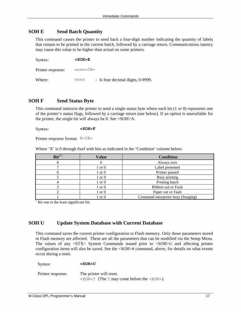
SOH E Send Batch Quantity
This command causes the printer to send back a four-digit number indicating the quantity of labelsthat remain to be printed in the current batch, followed by a carriage return. Communications latencymay cause this value to be higher than actual on some printers.
Syntax: <SOH>E
Printer response: nnnn<CR>
Where: nnnn - Is four decimal digits, 0-9999.
SOH F Send Status Byte
This command instructs the printer to send a single status byte where each bit (1 or 0) represents oneof the printer’s status flags, followed by a carriage return (see below). If an option is unavailable forthe printer, the single bit will always be 0. See <SOH>A.
Syntax: <SOH>F
Printer response format: X<CR>
Where ‘X’ is 0 through 0xef with bits as indicated in the ‘Condition’ column below:
Bit[1] Value Condition8 0 Always zero7 1 or 0 Label presented6 1 or 0 Printer paused5 1 or 0 Busy printing4 1 or 0 Printing batch3 1 or 0 Ribbon out or Fault2 1 or 0 Paper out or Fault1 1 or 0 Command interpreter busy (Imaging)
1 Bit one is the least significant bit.
SOH U Update System Database with Current Database
This command saves the current printer configuration to Flash memory. Only those parameters storedin Flash memory are affected. These are all the parameters that can be modified via the Setup Menu.The values of any <STX> System Commands issued prior to <SOH>U and affecting printerconfiguration items will also be saved. See the <SOH># command, above, for details on what eventsoccur during a reset.
Syntax: <SOH>U
Printer response: The printer will reset.<XON>T (The T may come before the <XON>).

Immediate Commands
18 M-Class DPL Programmer’s Manual
M-Class DPL Programmer’s Manual 19
System-Level Commands
IntroductionThe most commonly used commands are the System-Level Commands. These are used to load and storegraphic information, in addition to printer control. System-Level Commands are used to override defaultparameter values (fixed and selectable) and may be used before or after Immediate Commands but cannotbe issued among Label-Formatting Commands. System-Level Commands consist of the followingsequences:
1. Attention Getter, 0x02 or 0x7E, see Control Codes.
2. Command Character
3. Parameters (if any).
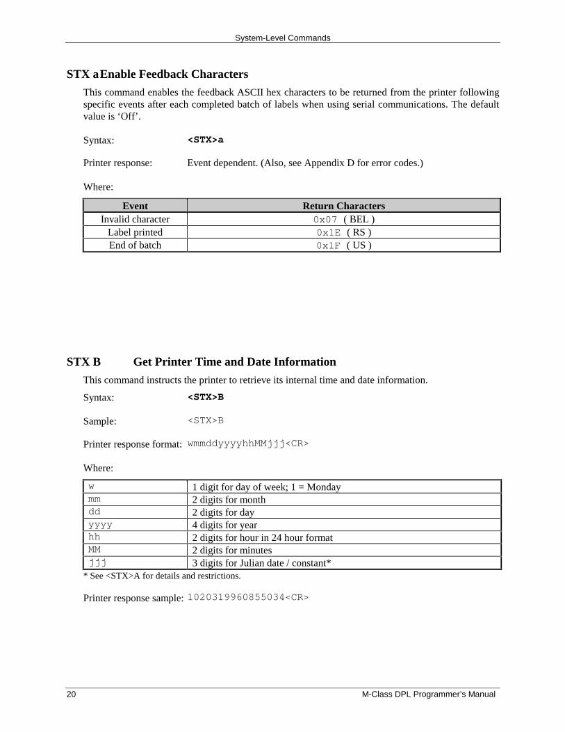
STX A Set Time and Date
This command sets the time and date. The initial setting of the date will be stored in the printer’sinternal inch counter. This date can be verified by printing a Configuration Label.
Syntax: <STX>AwmmddyyyyhhMMjjj
Where:
w 1 digit for day of week; 1 = Monday; 7 = Sundaymm 2 digits for monthdd 2 digits for dayyyyy 4 digits for yearhh 2 digits for hour in 24 hour formatMM 2 digits for minutesjjj 3 digits for Julian date (numerical day of the year) / constant; see notes below
Sample: <STX>A1020319960855034
Printed response: Mon. Feb 3, 1996, 8:55AM, 034
� Notes: (1) When set to 000, the Julian date is automatically calculated; otherwise, the Julian date will printas that entered number, without daily increments. If factory defaults are restored the actual Juliandate will also be restored.
(2) Printers without the Real Time Clock option lose the set time/date when power is removed.
(3) Response format is variable; see the Special Label-Formatting Command <STX>T.
System-Level Commands
20 M-Class DPL Programmer’s Manual
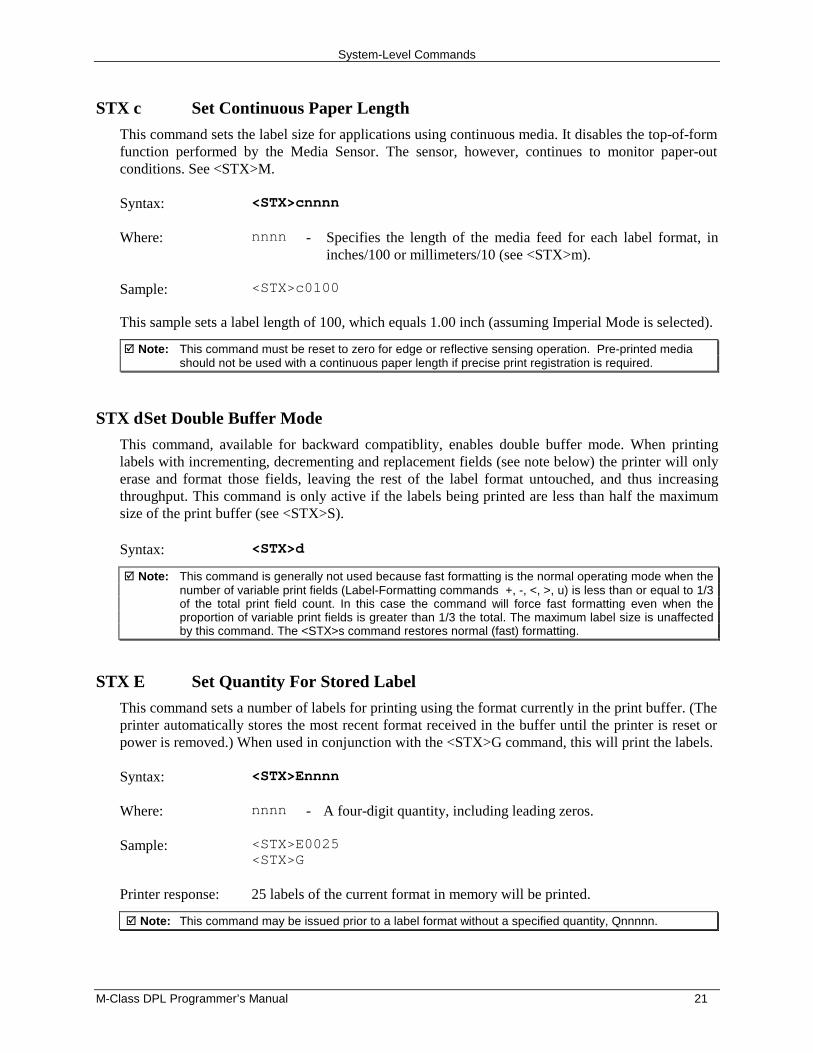
STX aEnable Feedback Characters
This command enables the feedback ASCII hex characters to be returned from the printer followingspecific events after each completed batch of labels when using serial communications. The defaultvalue is ‘Off’.
Syntax: <STX>a
Printer response: Event dependent. (Also, see Appendix D for error codes.)
Where:
Event Return CharactersInvalid character 0x07 ( BEL )
Label printed 0x1E ( RS )End of batch 0x1F ( US )
STX B Get Printer Time and Date Information
This command instructs the printer to retrieve its internal time and date information.
Syntax: <STX>B
Sample: <STX>B
Printer response format: wmmddyyyyhhMMjjj<CR>
Where:
w 1 digit for day of week; 1 = Mondaymm 2 digits for monthdd 2 digits for dayyyyy 4 digits for yearhh 2 digits for hour in 24 hour formatMM 2 digits for minutesjjj 3 digits for Julian date / constant*
* See <STX>A for details and restrictions.
Printer response sample: 1020319960855034<CR>
System-Level Commands
M-Class DPL Programmer’s Manual 21
STX c Set Continuous Paper Length
This command sets the label size for applications using continuous media. It disables the top-of-formfunction performed by the Media Sensor. The sensor, however, continues to monitor paper-outconditions. See <STX>M.
Syntax: <STX>cnnnn
Where: nnnn - Specifies the length of the media feed for each label format, ininches/100 or millimeters/10 (see <STX>m).
Sample: <STX>c0100
This sample sets a label length of 100, which equals 1.00 inch (assuming Imperial Mode is selected).
� Note: This command must be reset to zero for edge or reflective sensing operation. Pre-printed mediashould not be used with a continuous paper length if precise print registration is required.
STX dSet Double Buffer Mode
This command, available for backward compatiblity, enables double buffer mode. When printinglabels with incrementing, decrementing and replacement fields (see note below) the printer will onlyerase and format those fields, leaving the rest of the label format untouched, and thus increasingthroughput. This command is only active if the labels being printed are less than half the maximumsize of the print buffer (see <STX>S).
Syntax: <STX>d
� Note: This command is generally not used because fast formatting is the normal operating mode when thenumber of variable print fields (Label-Formatting commands +, -, <, >, u) is less than or equal to 1/3of the total print field count. In this case the command will force fast formatting even when theproportion of variable print fields is greater than 1/3 the total. The maximum label size is unaffectedby this command. The <STX>s command restores normal (fast) formatting.
STX E Set Quantity For Stored Label
This command sets a number of labels for printing using the format currently in the print buffer. (Theprinter automatically stores the most recent format received in the buffer until the printer is reset orpower is removed.) When used in conjunction with the <STX>G command, this will print the labels.
Syntax: <STX>Ennnn
Where: nnnn - A four-digit quantity, including leading zeros.
Sample: <STX>E0025<STX>G
Printer response: 25 labels of the current format in memory will be printed.
� Note: This command may be issued prior to a label format without a specified quantity, Qnnnnn.
System-Level Commands
22 M-Class DPL Programmer’s Manual
STX e Select Edge Sensor
This command enables transmissive (see-through) sensing for top-of-form detection of die-cut, andholed or notched media. This Media Sensor will detect a minimum gap of 0.1 inches (2.54 mm)between labels (see the Operator’s Manual for media requirements). Use the <STX>O command toadjust the print position. This is the printer default setting at power-up or reset.
Syntax: <STX>e
� Note: This command is ignored when <STX>cnnnn is issued with a non-zero value for nnnn.
STX F Form Feed
This commands the printer to form feed to the next start of print.
Syntax: <STX>F
Printer response: The printer will form feed.
� Note: Following a reset, if the length of the first label fed is less than the label offset value (defined by the<STX>O command) the printer will advance past that label until a top-of-form is detected, or untilthe offset is reached, skipping labels as necessary, unless the Label Alignment function isenabled.
STX f Set Form Stop Position (Backfeed Command)
This sets the stop position of the printed label, allowing the label to stop at a point past the start-of-print position. When the next label format is sent, the printer motor reverses direction to retract themedia to the start-of-print position. If quantities of more than one label are requested, the printer willoperate without backfeeding. A backfeed will then only occur when printing has stopped for a fewseconds.
Syntax: <STX>fnnn
Where: nnn - Is a three-digit distance from the Media Sensor, in inches/100 ormm/10. This distance is independent of the start-of-print position(<STX>O), yet it must be greater than the start-of-print position totake effect.
Sample: <STX>f230
The sample sets a stop position distance of 230 (2.3 inches from the Media Sensor’s eye).
� Note: If the Stop Location in the printer’s menu system is set to AUTO, it will prevent the printer fromacknowledging this DPL command.
System-Level Commands
M-Class DPL Programmer’s Manual 23
STX G Print Last Label Format
This command prints a previously formatted label and restarts a canceled batch job following the lastprocessed label. This is used when there is a label format in the buffer. The <STX>E command isused to enter the quantity. (If the <STX>E command is not used only one label will print.)
Syntax: <STX>G
STX I Image Downloading
This command must precede image downloading from a host computer to the printer. The data thatimmediately follows the command string will be image data. If any of the 8-bit input formats are tobe used, it is necessary to disable the Immediate Command interpreter by executing an <SOH>Dcommand before issuing the <STX>I command. See Appendix M for more information. To print animage, see Generating Label Formats.
� Note: The native format for storing downloaded PCX and BMP images is RLE-2. This results in a bettercompression ratio for gray-scale images and for images with very large areas with either black orwhite, effectively resulting in more module space for downloaded images.
Syntax: <STX>Iabfnn…n<CR>data
Where: a - Memory Module Bank Selection, A, B, or C; see Appendix J.
b - Data Type (optional), A or omit.
b Value: Image Data Value Range:A ASCII Characters 0-9, A-F, (7 bit)omitted 00-FF, (8 bit)
f - Format Designator
f Designator: Format Type:F 7-bit Datamax image load fileB .BMP 8-bit format (image flipped), black and
white (B&W)b .BMP 8-bit format (image as received), B&WI .IMG 8-bit format (image flipped), B&Wi .IMG 8-bit format (image as received), B&WP .PCX 8-bit format (image flipped), B&Wp .PCX 8-bit format (image as received), B&WR RLE-2 Native format
nn…n - Up to 16 characters used as an image name.
<CR> - 0x0d terminates the name.
data - Image data
Sample: <SOH>D<STX>IApTest <CR>data...data <CR>
The sample instructs the printer to (1) receive an 8-bit PCX image sent by the host in an 8-bit dataformat, (2) name the image ‘Test’, and (3) store it in memory module A.
System-Level Commands
24 M-Class DPL Programmer’s Manual
STX i Scalable Font Downloading
The command structure for downloading both IntelliFont (.CDI) and TrueType (.TTF) scalable fonts(font files may be single-byte or double-byte character systems) is as follows:
Syntax: <STX>imtnnName<CR>xx…xdata…
Where: m - Memory Module Designator to save this font to; see Appendix J.
t - Type of scalable font being downloaded:I = IntelliFontT = TrueType
nn - Two-digit font reference ID. Valid range is 50-99, 9A-9Z, 9a-9z,(base 62 numbers).
Name - The title, up to 16 characters, for this font.
<CR> - 0x0d terminates the Name.
xx…x - Eight-digit size of the font data, number of bytes, hexadecimal,padded with leading zeros.
data - The scalable font data.
Sample: <STX>iET52Tree Frog<CR>000087C2data...
This sample downloads a TrueType font to module ‘A’, assigns it the font ID of 52 and the name“Tree Frog”. The size of the font data is 0x87C2 bytes.
STX J Set Pause for Each Label
This command causes the printer to pause after printing each label and is intended for use with thepeel mechanism or tear bar when the Present Sensor option is not installed. After removing the label,the PAUSE Button must be pushed in order to print the next label. (The printer must be reset to clearthe <STX >J command.)
Syntax: <STX>J
STX k Test RS-232 Port
This command instructs the printer to transmit the character Y from the printer’s RS-232 port.(Failure to receive a ‘Y’ could indicate an interfacing problem.)
Syntax: <STX>k
Printer response: Y
System-Level Commands
M-Class DPL Programmer’s Manual 25
STX L Enter Label-Formatting Command Mode
This command switches the printer to the Label-Formatting Command mode. Once in this mode, theprinter expects to receive Record Structures and Label-Formatting Commands. Immediate, System-Level, and Font-Loading commands will be ignored until the label-formatting mode is terminatedwith E, s, or X, (see Label-Formatting Commands for additional information).
Syntax: <STX>L
STX M Set Maximum Label Length
This command instructs the printer move media this distance in search of the top-of-form (label edge,notch, black mark, etc.) before declaring a paper fault. A paper fault condition can occur if thissetting is too close (within 0.1 inch [2.54 mm]) to the physical length of the label. Therefore, it isgood practice to set this command to 2.5 to 3 times the actual label length used. The minimum valueshould be at least 5” (127 mm).
Syntax: <STX>Mnnnn
Where: nnnn - Is a four-digit length, 0000-9999, in/100 or mm/10. Maximumsetting is 9999 (99.99 inches or 2540 mm). The default setting is16 inches/ 406.4 mm
Sample: <STX>M0500
The sample sets a maximum travel distance of 5 inches (unless printer is in metric mode, see<STX>m).
STX m Set Metric Mode
This command sets the printer to interpret measurements as metric values (e.g., <STX>c0100 willequal 10.0 mm). The default is Imperial (inches) Mode (see <STX>n).
Syntax: <STX>m
STX n Set Imperial (Inches) Mode
This command sets the printer to interpret measurements as imperial values (e.g., <STX>c0100 willequal 1.00 inch). The printer defaults to this mode.
Syntax: <STX>n
System-Level Commands
26 M-Class DPL Programmer’s Manual
STX O Set Start of Print Position
This sets the point to begin printing relative to the top-of-form (the label’s edge as detected by theMedia Sensor). The printer will feed from the top of form to the value specified in this command tobegin printing. This value operates independently of the <STX>f command.
Syntax: <STX>Onnnn
Where: nnnn - Is a four-digit offset value. The “zero” setting is the default value,and settings below 50 are adjusted back to the default value. Thedefault setting is 0220 in Imperial Mode (0559 in metric).
Sample: <STX>O0300
The sample sets a start of print position of 3.0 inches (unless in Metric Mode, see <STX>m).
STX o Cycle Cutter
This command will cause the (optional) cutter mechanism to immediately perform a cut after allpreviously received commands are executed. The cutter must be installed, enabled and the interlockclosed for operation.
Syntax: <STX>o
STX P Character (Hex) Dump Mode
This command instructs the printer to enter the Character Hex Dump Mode (also known as ASCIIdump or monitor mode). Data sent to the printer following this command will be printed in rawASCII format. Labels must be at least four inches (102 mm) long and as wide as the maximum printwidth. This command has the same effect as turning the printer ‘On’ while pressing the FEEDButton; however, no Configuration/Test Pattern label is printed. To return to normal operation theprinter must be manually reset.
Syntax: <STX>P
STX p Controlled Pause
This command will cause the printer to pause only after all previously received commands areexecuted. This controlled pause is often useful between batches of labels. (This command will notclear the pause condition, see <SOH>B).
Syntax: <STX>p
System-Level Commands
M-Class DPL Programmer’s Manual 27
STX Q Clear All Modules
This command instructs the printer to clear all Flash and DRAM modules (see the Operator’sManual of the corresponding printer for applicable memory options). All stored data in the selectedmodule will be destroyed.
Syntax: <STX>Q
STX q Clear Module
This command clears the selected Flash or DRAM module. If a module is corrupted during normaloperations (identifiable when the printer responds with a ‘No Modules Available’ message to a<STX>W command), it must be cleared. All stored data will be destroyed.
Syntax: <STX>qa
Where: a - Memory module designator, A – C; see Appendix J.
Sample: <STX>qA
The above sample clears memory module A.
� Notes: (1) If a module directory intermittently returns the message ‘No Modules Available’ or if datacontinuously becomes corrupted, the module may be at the end of its service. However, beforeconcluding that a module is defective cycle the printer’s power and test the module.
(2) Some Flash Memory Expansion options must have jumpers installed to perform thiscommand.
STX r Select Reflective Sensor
This command enables reflective (black mark) sensing for top-of-form detection of rolled butt-cut,and fan-fold or tag stocks with reflective marks on the underside. This Media Sensor will detect aminimum mark of 0.1 inches (2.54 mm) between labels (see the Operators Manual for mediarequirements). The end of the black mark determines the top of form. Use the <STX>O command toadjust the print position.
Syntax: <STX>r
Default: Edge sensing
STX SSet Feed Speed
This command controls the rate at which media is output when the FEED Button is pressed.
Syntax: <STX>Sn
Where: n - Is a letter value (see Appendix K).
System-Level Commands
28 M-Class DPL Programmer’s Manual
STX s Set Single Buffer Mode
This command, available for backward compatiblity, instructs the printer to use single bufferoperation. In single buffer mode, the printer will erase and format all fields. This, in turn, decreasesprinter throughput when incremental, decremental, or replacement fields are used (see Label-Formatting Commands). See <STX>d.
Syntax: <STX>s
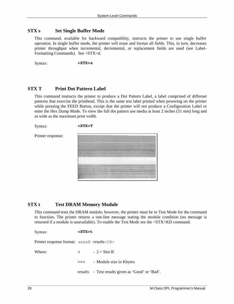
STX T Print Dot Pattern Label
This command instructs the printer to produce a Dot Pattern Label, a label comprised of differnetpatterns that exercise the printhead. This is the same test label printed when powering on the printerwhile pressing the FEED Button, except that the printer will not produce a Configuration Label orenter the Hex Dump Mode. To view the full dot pattern use media at least 2 inches (51 mm) long andas wide as the maximum print width.
Syntax: <STX>T
Printer response:
STX t Test DRAM Memory Module
This command tests the DRAM module; however, the printer must be in Test Mode for the commandto function. The printer returns a one-line message stating the module condition (no message isreturned if a module is unavailable). To enable the Test Mode see the <STX>KD command.
Syntax: <STX>t
Printer response format: axxxK results<CR>
Where: a - 2 = Slot B
xxx - Module size in Kbytes
results - Test results given as ‘Good’ or ‘Bad’.
System-Level Commands
M-Class DPL Programmer’s Manual 29
STX U Label Format String Replacement Field
This command places new label data into format fields to build a label. The new data string mustequal the original string length and contain valid data. To easily keep track of fields, place all of thefields to be updated with the command at the beginning of the label format. A maximum of 99 formatfields can be updated. Fields are numbered consecutively 01 to 99 in the order received.
A variant of the <STX>U command includes the truncate option ‘T’, where dynamic data that isshorter that the originally defined field length will not be padded, and the original maximum fieldlength is maintained for subsequent replacements. If this option is not used when dynamic data isshorter than the length of the originally defined data field, the field will be padded with blanks (orzero when the Format Record header specifies a numeric barcode).
Syntax: <STX>U[T]nnss…s<CR>
Where: nn - Is the format field number, 2 digits.
[T] - Truncate option
ss…s - Is the new string data, followed by a <CR>
Sample: <STX>L161100001000100data field 1<CR>161100001100110data field 2<CR>161100001200120data field 3<CR>Q0001E<STX>U01New data F1<CR><STX>U02New data F2<CR><STX>E0002<STX>G
The sample produces three labels. The first is formatted with the commands between <STX>L and E.The next two labels print with the replacement data contained in the <STX>U commands (see<STX>E and <STX>G).
System-Level Commands
30 M-Class DPL Programmer’s Manual
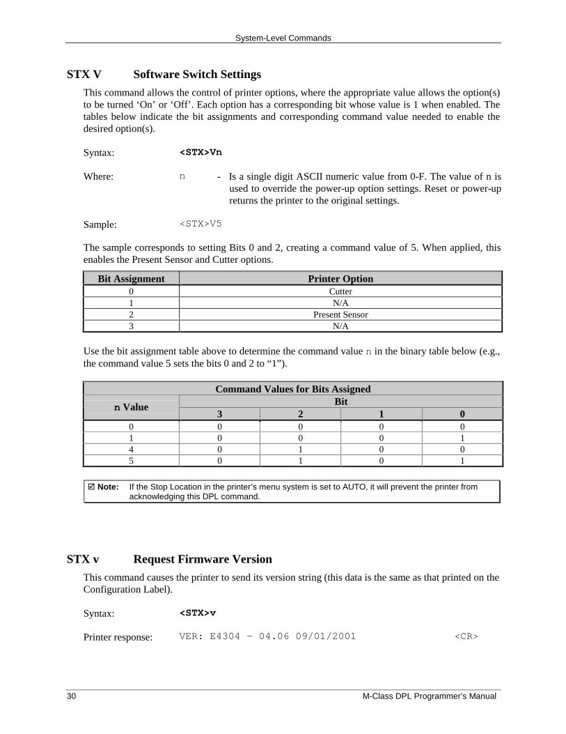
STX V Software Switch Settings
This command allows the control of printer options, where the appropriate value allows the option(s)to be turned ‘On’ or ‘Off’. Each option has a corresponding bit whose value is 1 when enabled. Thetables below indicate the bit assignments and corresponding command value needed to enable thedesired option(s).
Syntax: <STX>Vn
Where: n - Is a single digit ASCII numeric value from 0-F. The value of n isused to override the power-up option settings. Reset or power-upreturns the printer to the original settings.
Sample: <STX>V5
The sample corresponds to setting Bits 0 and 2, creating a command value of 5. When applied, thisenables the Present Sensor and Cutter options.
Bit Assignment Printer Option0 Cutter1 N/A2 Present Sensor3 N/A
Use the bit assignment table above to determine the command value n in the binary table below (e.g.,the command value 5 sets the bits 0 and 2 to “1”).
Command Values for Bits AssignedBit
n Value3 2 1 0
0 0 0 0 01 0 0 0 14 0 1 0 05 0 1 0 1
� Note: If the Stop Location in the printer’s menu system is set to AUTO, it will prevent the printer fromacknowledging this DPL command.
STX v Request Firmware Version
This command causes the printer to send its version string (this data is the same as that printed on theConfiguration Label).
Syntax: <STX>v
Printer response: VER: E4304 – 04.06 09/01/2001 <CR>
System-Level Commands
M-Class DPL Programmer’s Manual 31
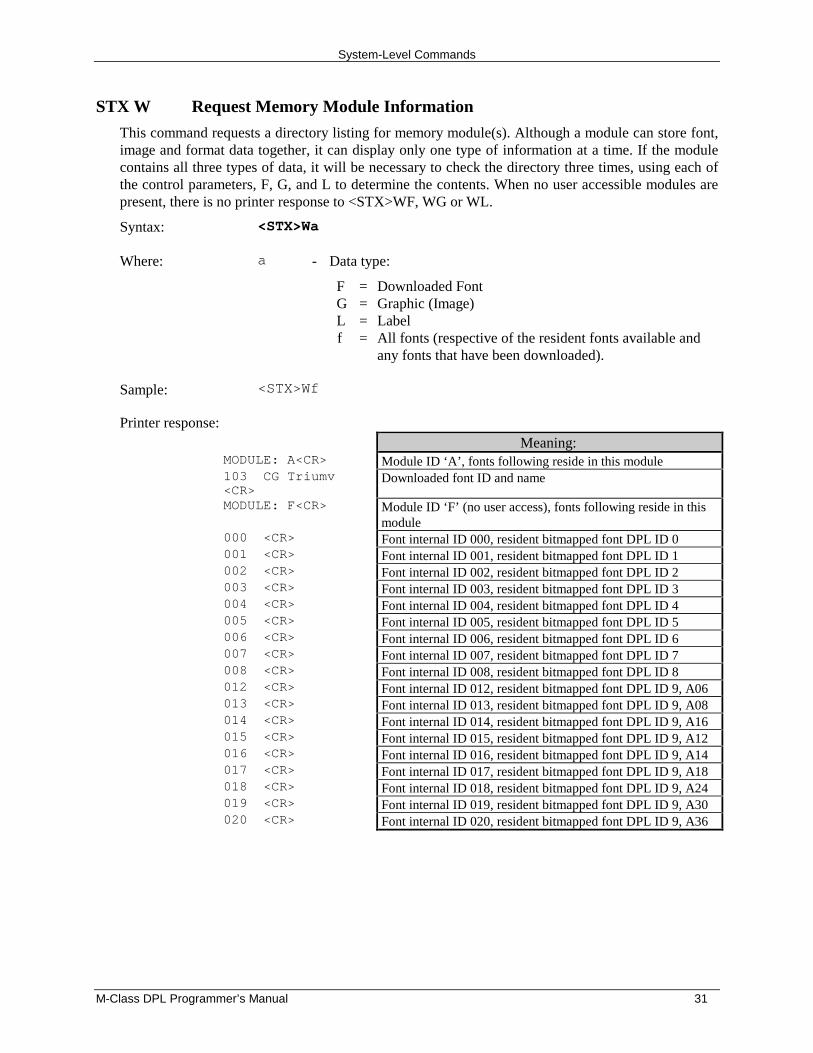
STX W Request Memory Module Information
This command requests a directory listing for memory module(s). Although a module can store font,image and format data together, it can display only one type of information at a time. If the modulecontains all three types of data, it will be necessary to check the directory three times, using each ofthe control parameters, F, G, and L to determine the contents. When no user accessible modules arepresent, there is no printer response to <STX>WF, WG or WL.
Syntax: <STX>Wa
Where: a - Data type:
FGLf
====
Downloaded FontGraphic (Image)LabelAll fonts (respective of the resident fonts available andany fonts that have been downloaded).
Sample: <STX>Wf
Printer response:Meaning:
MODULE: A<CR> Module ID ‘A’, fonts following reside in this module103 CG Triumv<CR>
Downloaded font ID and name
MODULE: F<CR> Module ID ‘F’ (no user access), fonts following reside in thismodule
000 <CR> Font internal ID 000, resident bitmapped font DPL ID 0001 <CR> Font internal ID 001, resident bitmapped font DPL ID 1002 <CR> Font internal ID 002, resident bitmapped font DPL ID 2003 <CR> Font internal ID 003, resident bitmapped font DPL ID 3004 <CR> Font internal ID 004, resident bitmapped font DPL ID 4005 <CR> Font internal ID 005, resident bitmapped font DPL ID 5006 <CR> Font internal ID 006, resident bitmapped font DPL ID 6007 <CR> Font internal ID 007, resident bitmapped font DPL ID 7008 <CR> Font internal ID 008, resident bitmapped font DPL ID 8012 <CR> Font internal ID 012, resident bitmapped font DPL ID 9, A06013 <CR> Font internal ID 013, resident bitmapped font DPL ID 9, A08014 <CR> Font internal ID 014, resident bitmapped font DPL ID 9, A16015 <CR> Font internal ID 015, resident bitmapped font DPL ID 9, A12016 <CR> Font internal ID 016, resident bitmapped font DPL ID 9, A14017 <CR> Font internal ID 017, resident bitmapped font DPL ID 9, A18018 <CR> Font internal ID 018, resident bitmapped font DPL ID 9, A24019 <CR> Font internal ID 019, resident bitmapped font DPL ID 9, A30020 <CR> Font internal ID 020, resident bitmapped font DPL ID 9, A36
System-Level Commands
32 M-Class DPL Programmer’s Manual
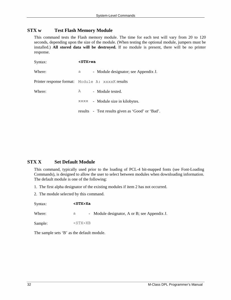
STX w Test Flash Memory ModuleThis command tests the Flash memory module. The time for each test will vary from 20 to 120seconds, depending upon the size of the module. (When testing the optional module, jumpers must beinstalled.) All stored data will be destroyed. If no module is present, there will be no printerresponse.
Syntax: <STX>wa
Where: a - Module designator; see Appendix J.
Printer response format: Module A: xxxxK results
Where: A - Module tested.
xxxx - Module size in kilobytes.
results - Test results given as ‘Good’ or ‘Bad’.
STX X Set Default Module
This command, typically used prior to the loading of PCL-4 bit-mapped fonts (see Font-LoadingCommands), is designed to allow the user to select between modules when downloading information.The default module is one of the following:
1. The first alpha designator of the existing modules if item 2 has not occurred.
2. The module selected by this command.
Syntax: <STX>Xa
Where: a - Module designator, A or B; see Appendix J.
Sample: <STX>XB
The sample sets ‘B’ as the default module.
System-Level Commands
M-Class DPL Programmer’s Manual 33
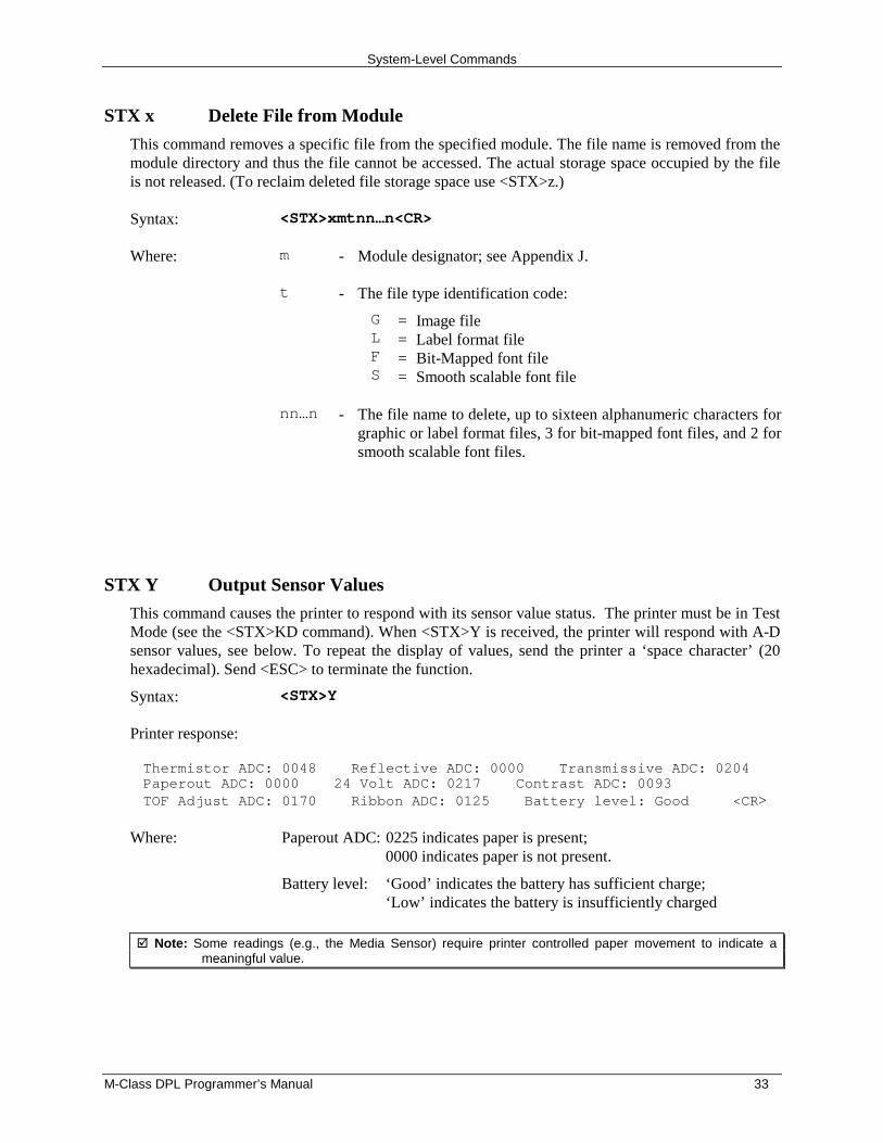
STX x Delete File from Module
This command removes a specific file from the specified module. The file name is removed from themodule directory and thus the file cannot be accessed. The actual storage space occupied by the fileis not released. (To reclaim deleted file storage space use <STX>z.)
Syntax: <STX>xmtnn…n<CR>
Where: m - Module designator; see Appendix J.
t - The file type identification code:
GLFS
====
Image fileLabel format fileBit-Mapped font fileSmooth scalable font file
nn…n - The file name to delete, up to sixteen alphanumeric characters forgraphic or label format files, 3 for bit-mapped font files, and 2 forsmooth scalable font files.
STX Y Output Sensor Values
This command causes the printer to respond with its sensor value status. The printer must be in TestMode (see the <STX>KD command). When <STX>Y is received, the printer will respond with A-Dsensor values, see below. To repeat the display of values, send the printer a ‘space character’ (20hexadecimal). Send <ESC> to terminate the function.
Syntax: <STX>Y
Printer response:
Thermistor ADC: 0048 Reflective ADC: 0000 Transmissive ADC: 0204Paperout ADC: 0000 24 Volt ADC: 0217 Contrast ADC: 0093TOF Adjust ADC: 0170 Ribbon ADC: 0125 Battery level: Good <CR>
Where: Paperout ADC: 0225 indicates paper is present;0000 indicates paper is not present.
Battery level: ‘Good’ indicates the battery has sufficient charge;‘Low’ indicates the battery is insufficiently charged
� Note: Some readings (e.g., the Media Sensor) require printer controlled paper movement to indicate ameaningful value.
System-Level Commands
34 M-Class DPL Programmer’s Manual
STX y Select Font Symbol Set
This command selects the scalable font symbol set. The selected symbol set remains active untilanother symbol set is selected. See Appendices E, I, and the <STX>KS command for moreinformation. Option dependant. Not all symbol sets can be used with all fonts.
Syntax: <STX>ySxx
Where: S - Byte size designation, see Appendix H.S = Single-byte symbol setsU = Double-byte symbol sets
xx - Symbol set selection.
Sample: <STX>ySPM
The sample selects the PC-850 multilingual set.
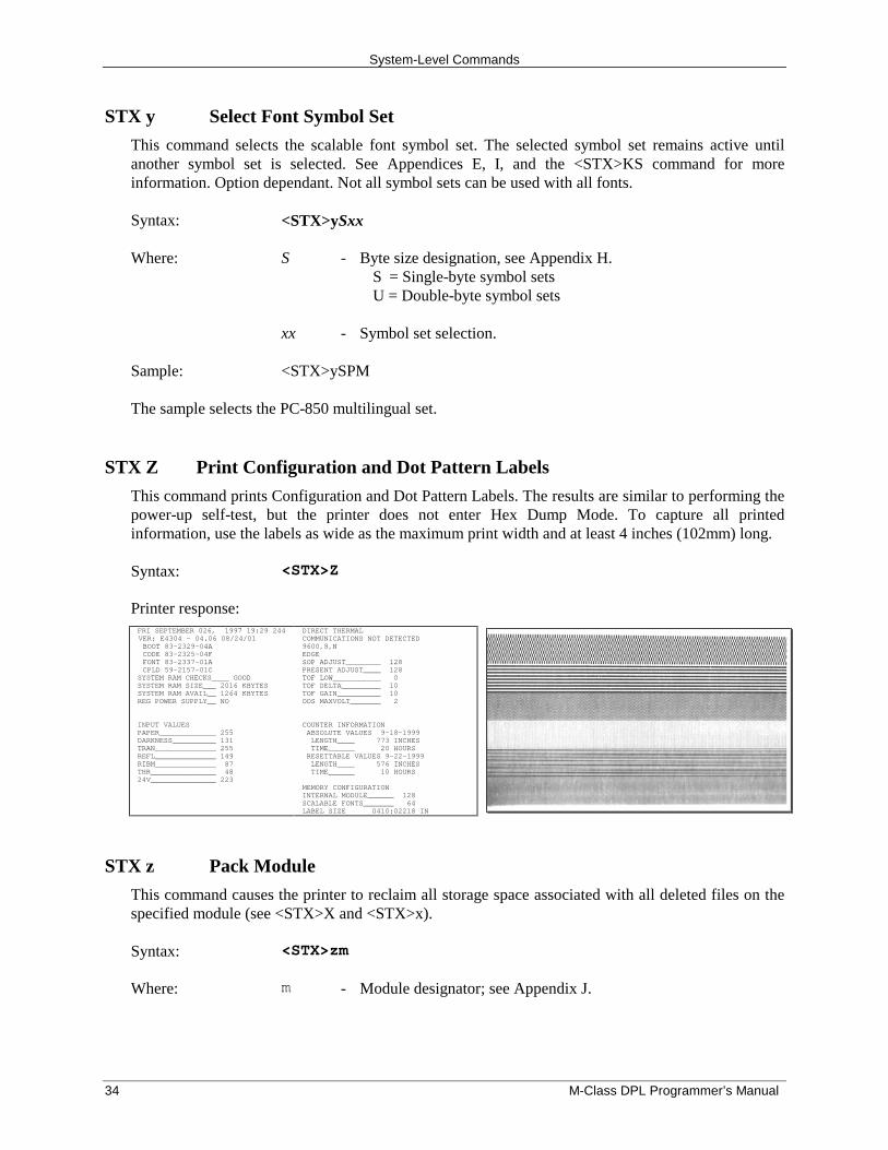
STX Z Print Configuration and Dot Pattern Labels
This command prints Configuration and Dot Pattern Labels. The results are similar to performing thepower-up self-test, but the printer does not enter Hex Dump Mode. To capture all printedinformation, use the labels as wide as the maximum print width and at least 4 inches (102mm) long.
Syntax: <STX>Z
Printer response: FRI SEPTEMBER 026, 1997 19:29 244VER: E4304 - 04.06 08/24/01 BOOT 83-2329-04A CODE 83-2325-04F FONT 83-2337-01A CPLD 59-2157-01C SYSTEM RAM CHECKS____ GOOD SYSTEM RAM SIZE___ 2016 KBYTES SYSTEM RAM AVAIL__ 1264 KBYTES REG POWER SUPPLY__ NO INPUT VALUES PAPER_____________ 255 DARKNESS__________ 131 TRAN______________ 255 REFL______________ 149 RIBM______________ 87 THR_______________ 48 24V_______________ 223
DIRECT THERMAL COMMUNICATIONS NOT DETECTED 9600,8,N EDGE SOP ADJUST________ 128 PRESENT ADJUST____ 128 TOF LOW___________ 0 TOF DELTA_________ 10 TOF GAIN__________ 10 OOS MAXVOLT_______ 2 COUNTER INFORMATION ABSOLUTE VALUES 9-18-1999 LENGTH____ 773 INCHES TIME______ 20 HOURS RESETTABLE VALUES 9-22-1999 LENGTH____ 576 INCHES TIME______ 10 HOURS MEMORY CONFIGURATION INTERNAL MODULE______ 128 SCALABLE FONTS_______ 64LABEL SIZE 0410:02218 IN
STX z Pack Module
This command causes the printer to reclaim all storage space associated with all deleted files on thespecified module (see <STX>X and <STX>x).
Syntax: <STX>zm
Where: m - Module designator; see Appendix J.
M-Class DPL Programmer’s Manual 35
Extended System Commands
IntroductionExtended System Commands expand certain System-Level Commands, providing extra printer control.Extended System Commands are issued in the same context as System-Level Commands. The table belowlists the commands.
Command <STX>K Command CharacterBackfeed Time Delay b
Get Configuration C
Set Configuration c
Database Configuration D
Character Encoding E
Set Present Distance f
Memory Configuration, Internal Module M
Query Memory Configuration Q
Reset Memory Configuration R
Reset Resettable Counters r
Memory Configuration, Scalable Font Cache S
Memory Configuration, Printable Label Width W
Table 5-1: Extended System Command Characters
STX K Memory Configuration
This command configures the available DRAM as a method for managing printer memory. TheDRAM memory includes standard DRAM. Memory can be assigned to specific entities or functionsin units of 4KB blocks. The allocation(s) as set by this command, draw from the same memory pool,control the sizes of internal Module A, Scalable Cache, and label width. The command indirectlyaffects maximum print length and label throughput; see note below. The printer executes the memoryconfiguration specified by the command during the next idle period following its receipt, and isstored in Flash memory then reinstated upon a power-up or reset. If the total requested memoryallocation exceeds the configurable memory available, contains no fields, or for configurations notspecified, the command will be rejected and the printer will assume its previous configuration. Anyof the three fields are optional, and are separated by the colon. Brackets indicate optional fields.
Syntax: <STX>Kix[:jy][:kz]<CR>
Sample: <STX>KM0020:S0015<CR>
In the sample, memory is allocated 20*4*1024 bytes for module A space and 15*4*1024 bytes forthe scalable cache.
Extended System Commands
36 M-Class DPL Programmer’s Manual
Where: i, j, k are M, S, or W; x, y, z are four-digit maximum numbers of 4K byte blocks orinches/100 or (mm/10) as described below.
M Represents the start of a sequence (up to five characters) that assigns memory to theInternal Module A. If this field does not appear, then the Internal Module is notaffected. If no Internal Module exists, it will be created and formatted. ExistingInternal Modules will be erased, re-sized and formatted. The number that follows theM is a decimal number (up to four digits) that specifies the size in 4KB blocks ofmemory to assign to the Internal Module. A value of “0000” will delete the InternalModule (see Appendix J for additional information).
S Represents the start of a sequence (up to five characters) that assigns the amount ofinternal memory allocated to the smooth scalable font processor. This field is optional;if it does not appear, the current amount of memory assigned to the smooth scalablefont processor will remain unchanged. The allocation must be at least 15 (60KB) toprint scalable fonts, and at least 30 for double-byte fonts. The number that follows theS is a decimal number (up to four digits) that specifies the size in 4 KB blocks toassign to the smooth scalable font processor. Any value less than the minimumrequirement results in the amount assigned to be zero (0), thereby disabling theprinting of smooth scalable fonts. The recommended value is 0025 (100KB).
W Represents the start of a sequence (up to five characters) that sets the printable labelwidth. Setting a width smaller than the natural (maximum) width of the printereffectively extends printable label length. This field is optional; if it does not appear,the current printable label width is left unchanged. The number that follows the W is adecimal number (up to four digits) that specifies the printable label width in either100ths of an inch or millimeters, depending on the current units setting of the printer(imperial or metric). If the value specified exceeds the printable width of the printer,the printable label width is set to the maximum. If the value specified is less than theminimum value allowed (200) then the printable label width is set to the minimumallowed value.
� Note: Label printing requirements may be computed as bytes (label print length * width allocation *printhead resolution / 8). For maximum throughput, the memory allocated should allow for aminimum of three times the computed requirement, or the available label length (as determined by<STX>KQ command) should be three times the label print length.
STX Kb Backfeed Time Delay
The backfeed time delay command controls the time a printed label is allowed to remain “presented”before being retracted to the start of print position.
Syntax: <STX>Kbnnn<CR>
Where: nnn - Seconds/10
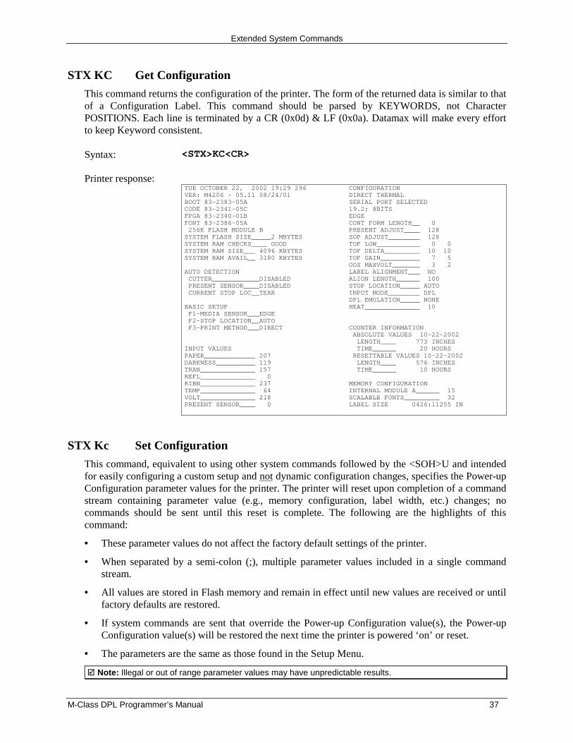
Extended System Commands
M-Class DPL Programmer’s Manual 37
STX KC Get Configuration
This command returns the configuration of the printer. The form of the returned data is similar to thatof a Configuration Label. This command should be parsed by KEYWORDS, not CharacterPOSITIONS. Each line is terminated by a CR (0x0d) & LF (0x0a). Datamax will make every effortto keep Keyword consistent.
Syntax: <STX>KC<CR>
Printer response: TUE OCTOBER 22, 2002 19:29 296 VER: M4206 - 05.11 08/24/01 BOOT 83-2383-05A CODE 83-2341-05C FPGA 83-2340-01B FONT 83-2386-05A 256K FLASH MODULE B SYSTEM FLASH SIZE_____2 MBYTES SYSTEM RAM CHECKS____ GOOD SYSTEM RAM SIZE___ 4096 KBYTES SYSTEM RAM AVAIL__ 3180 KBYTES AUTO DETECTION CUTTER____________DISABLED PRESENT SENSOR____DISABLED CURRENT STOP LOC__TEAR BASIC SETUP F1-MEDIA SENSOR___EDGE F2-STOP LOCATION__AUTO F3-PRINT METHOD___DIRECT INPUT VALUES PAPER_____________ 207 DARKNESS__________ 119 TRAN______________ 157 REFL______________ 0 RIBN______________ 237 TEMP______________ 64 VOLT______________ 218 PRESENT SENSOR____ 0
CONFIGURATION DIRECT THERMAL SERIAL PORT SELECTED 19.2; 8BITS EDGE CONT FORM LENGTH__ 0 PRESENT ADJUST____ 128 SOP ADJUST________ 128 TOF LOW___________ 0 0 TOF DELTA_________ 10 10 TOF GAIN__________ 7 5 OOS MAXVOLT_______ 3 2 LABEL ALIGNMENT___ NO ALIGN LENGTH______ 100 STOP LOCATION_____ AUTO INPUT MODE________ DPL DPL EMULATION_____ NONE HEAT______________ 10 COUNTER INFORMATION ABSOLUTE VALUES 10-22-2002 LENGTH____ 773 INCHES TIME______ 20 HOURS RESETTABLE VALUES 10-22-2002 LENGTH____ 576 INCHES TIME______ 10 HOURS MEMORY CONFIGURATION INTERNAL MODULE A______ 15 SCALABLE FONTS_________ 32 LABEL SIZE 0426:11255 IN
STX Kc Set Configuration
This command, equivalent to using other system commands followed by the <SOH>U and intendedfor easily configuring a custom setup and not dynamic configuration changes, specifies the Power-upConfiguration parameter values for the printer. The printer will reset upon completion of a commandstream containing parameter value (e.g., memory configuration, label width, etc.) changes; nocommands should be sent until this reset is complete. The following are the highlights of thiscommand:
• These parameter values do not affect the factory default settings of the printer.
• When separated by a semi-colon (;), multiple parameter values included in a single commandstream.
• All values are stored in Flash memory and remain in effect until new values are received or untilfactory defaults are restored.
• If system commands are sent that override the Power-up Configuration value(s), the Power-upConfiguration value(s) will be restored the next time the printer is powered ‘on’ or reset.
• The parameters are the same as those found in the Setup Menu.
� Note: Illegal or out of range parameter values may have unpredictable results.
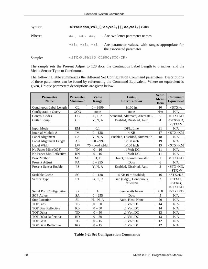
Extended System Commands
38 M-Class DPL Programmer’s Manual
Syntax: <STX>Kcaa1val1[;aaIvalI][;aanvaln]<CR>
Where: aa1, aaI, aan - Are two letter parameter names
val1, valI, valn - Are parameter values, with ranges appropriate forthe associated parameter
Sample: <STX>KcPA120;CL600;STC<CR>
The sample sets the Present Adjust to 120 dots, the Continuous Label Length to 6 inches, and theMedia Sensor Type to Continuous.
The following table summarizes the different Set Configuration Command parameters. Descriptionsof these parameters can be found by referencing the Command Equivalent. Where no equivalent isgiven, Unique parameters descriptions are given below.
ParameterName
ParameterMnemonic
ValueRange
Units /Interpretation
SetupMenuItem
CommandEquivalent
Continuous Label Length CL 0 – 9999 1/100 in. 10 <STX>cConfiguration Query QQQ none none N/A N/AControl Codes CC S, 1, 2 Standard, Alternate, Alternate-2 9 <STX>KDCutter Equip CE Y, N, A Enabled, Disabled, Auto 4 <STX>KD,
<STX>VInput Mode EM 0,1 DPL, Line 21 N/AInternal Module A IM 0 – 128 4 KB 17 <STX>KMLabel Alignment LA Y, N, A Enabled, Disabled, Automatic 18 N/ALabel Alignment Length AL 000 – 999 1/100 inch 19 N/ALabel Width LW 75 - head width 1/100 inch 15 <STX>KMNo Paper Min (OOS) TN 0 – 16 .1 Volt DC 11 N/ANo Paper Min Reflective RN 0 – 16 .1 Volt DC 11 N/APrint Method MT D, T Direct, Thermal Transfer 1 <STX>KDPresent Adjust PA 0 – 255 Dots 6 N/APresent Sensor Enable PS Y, N, A Enabled, Disabled, Auto 3 <STX>KD,
<STX>VScalable Cache SC 0 – 128 4 KB (0 = disabled) 16 <STX>KSSensor Type ST G, C, R Gap (Edge), Continuous,
Reflective2 <STX>e,
<STX>r,<STX>KD
Serial Port Configuration SP A See details below 7, 8 <STX>KDSOP Adjust SA 0 – 255 Dots 5 N/AStop Location SL H, , N, A Auto, Host, None 20 N/ATOF Bias TB 0 – 50 .1 Volt DC 14 N/ATOF Bias Reflective RB 0 – 50 .1 Volt DC 14 N/ATOF Delta TD 0 – 50 .1 Volt DC 13 N/ATOF Delta Reflective RD 0 – 50 .1 Volt DC 13 N/ATOF Gain TG 0 – 15 .1 Volt DC 12 N/ATOF Gain Reflective RG 0 – 15 .1 Volt DC 12 N/A
Table 5-2: Set Configuration Commands
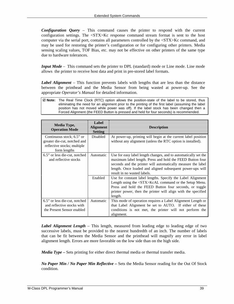
Extended System Commands
M-Class DPL Programmer’s Manual 39
Configuration Query – This command causes the printer to respond with the currentconfiguration settings. The <STX>Kc response command stream format is sent to the hostcomputer via the serial port, contains all parameters controlled by the <STX>Kc command, andmay be used for restoring the printer’s configuration or for configuring other printers. Mediasensing scaling values, TOF Bias, etc. may not be effective on other printers of the same typedue to hardware tolerances.
Input Mode – This command sets the printer to DPL (standard) mode or Line mode. Line modeallows the printer to receive host data and print in pre-stored label formats.
Label Alignment – This function prevents labels with lengths that are less than the distancebetween the printhead and the Media Sensor from being wasted at power-up. See theappropriate Operator’s Manual for detailed information.
� Note: The Real Time Clock (RTC) option allows the position-state of the label to be stored, thuseliminating the need for an alignment prior to the printing of the first label (assuming the labelposition has not moved while power was off). If the label stock has been changed then aForced Alignment (the FEED Button is pressed and held for four seconds) is recommended.
Media Type,Operation Mode
LabelAlignment
SettingDescription
Continuous stock; 6.5” orgreater die-cut, notched andreflective stocks; multiple
form lengths
Disabled At power-up, printing will begin at the current label positionwithout any alignment (unless the RTC option is installed).
Automatic Use for easy label length changes, and to automatically set themaximum label length. Press and hold the FEED Button fourseconds and the printer will automatically measure the labellength. Once loaded and aligned subsequent power-ups willresult in no wasted labels.
6.5” or less die-cut, notchedand reflective stocks
Enabled Use for constant label lengths. Specify the Label AlignmentLength using the <STX>KcAL command or the Setup Menu.Press and hold the FEED Button four seconds, or toggleprinter power, then the printer will align with the specifiedlength.
6.5” or less die-cut, notchedand reflective stocks with
the Present Sensor enabled
Automatic This mode of operation requires a Label Alignment Length orthat Label Alignment be set to AUTO. If either of theseconditions is not met, the printer will not perform thealignment.
Label Alignment Length – This length, measured from leading edge to leading edge of twosuccessive labels, must be provided to the nearest hundredth of an inch. The number of labelsthat can be fit between the Media Sensor and the printhead will magnify any error in labelalignment length. Errors are more favorable on the low side than on the high side.
Media Type – Sets printing for either direct thermal media or thermal transfer media.
No Paper Min / No Paper Min Reflective – Sets the Media Sensor reading for the Out Of Stockcondition.
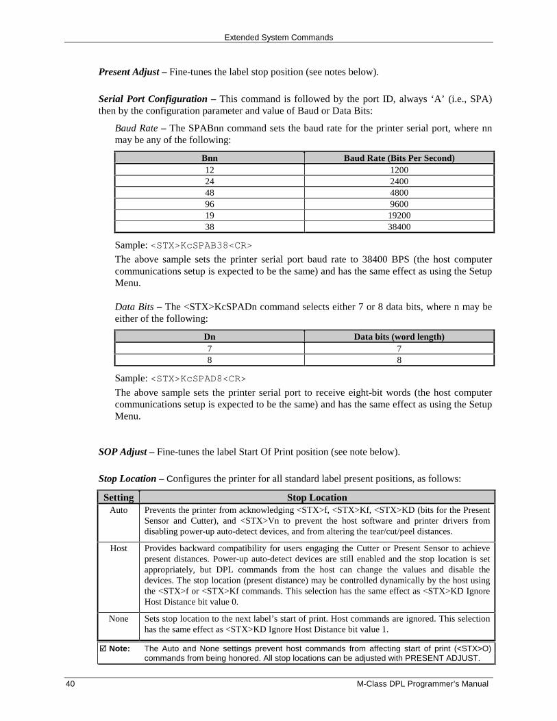
Extended System Commands
40 M-Class DPL Programmer’s Manual
Present Adjust – Fine-tunes the label stop position (see notes below).
Serial Port Configuration – This command is followed by the port ID, always ‘A’ (i.e., SPA)then by the configuration parameter and value of Baud or Data Bits:
Baud Rate – The SPABnn command sets the baud rate for the printer serial port, where nnmay be any of the following:
Bnn Baud Rate (Bits Per Second)12 120024 240048 480096 960019 1920038 38400
Sample: <STX>KcSPAB38<CR>
The above sample sets the printer serial port baud rate to 38400 BPS (the host computercommunications setup is expected to be the same) and has the same effect as using the SetupMenu.
Data Bits – The <STX>KcSPADn command selects either 7 or 8 data bits, where n may beeither of the following:
Dn Data bits (word length)7 78 8
Sample: <STX>KcSPAD8<CR>
The above sample sets the printer serial port to receive eight-bit words (the host computercommunications setup is expected to be the same) and has the same effect as using the SetupMenu.
SOP Adjust – Fine-tunes the label Start Of Print position (see note below).
Stop Location – Configures the printer for all standard label present positions, as follows:
Setting Stop LocationAuto Prevents the printer from acknowledging <STX>f, <STX>Kf, <STX>KD (bits for the Present
Sensor and Cutter), and <STX>Vn to prevent the host software and printer drivers fromdisabling power-up auto-detect devices, and from altering the tear/cut/peel distances.
Host Provides backward compatibility for users engaging the Cutter or Present Sensor to achievepresent distances. Power-up auto-detect devices are still enabled and the stop location is setappropriately, but DPL commands from the host can change the values and disable thedevices. The stop location (present distance) may be controlled dynamically by the host usingthe <STX>f or <STX>Kf commands. This selection has the same effect as <STX>KD IgnoreHost Distance bit value 0.
None Sets stop location to the next label’s start of print. Host commands are ignored. This selectionhas the same effect as <STX>KD Ignore Host Distance bit value 1.
� Note: The Auto and None settings prevent host commands from affecting start of print (<STX>O)commands from being honored. All stop locations can be adjusted with PRESENT ADJUST.
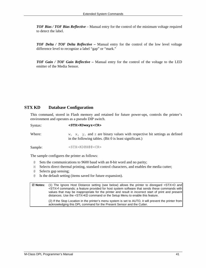
Extended System Commands
M-Class DPL Programmer’s Manual 41
TOF Bias / TOF Bias Reflective – Manual entry for the control of the minimum voltage requiredto detect the label.
TOF Delta / TOF Delta Reflective – Manual entry for the control of the low level voltagedifference level to recognize a label “gap” or “mark.”
TOF Gain / TOF Gain Reflective – Manual entry for the control of the voltage to the LEDemitter of the Media Sensor.
STX KD Database Configuration
This command, stored in Flash memory and retained for future power-ups, controls the printer’senvironment and operates as a pseudo DIP switch.
Syntax: <STX>KDwxyz<CR>
Where: w, x, y, and z are binary values with respective bit settings as definedin the following tables. (Bit 0 is least significant.)
Sample: <STX>KD@H@@<CR>
The sample configures the printer as follows:
@ Sets the communications to 9600 baud with an 8-bit word and no parity;H Selects direct thermal printing, standard control characters, and enables the media cutter;@ Selects gap sensing;@ Is the default setting (items saved for future expansion).
� Notes: (1) The Ignore Host Distance setting (see below) allows the printer to disregard <STX>O and<STX>f commands; a feature provided for host system software that sends these commands withvalues that may be inappropriate for the printer and result in incorrect start of print and presentdistances. Use the <STX>KD command or the Setup Menu to enable this feature.
(2) If the Stop Location in the printer’s menu system is set to AUTO, it will prevent the printer fromacknowledging this DPL command for the Present Sensor and the Cutter.
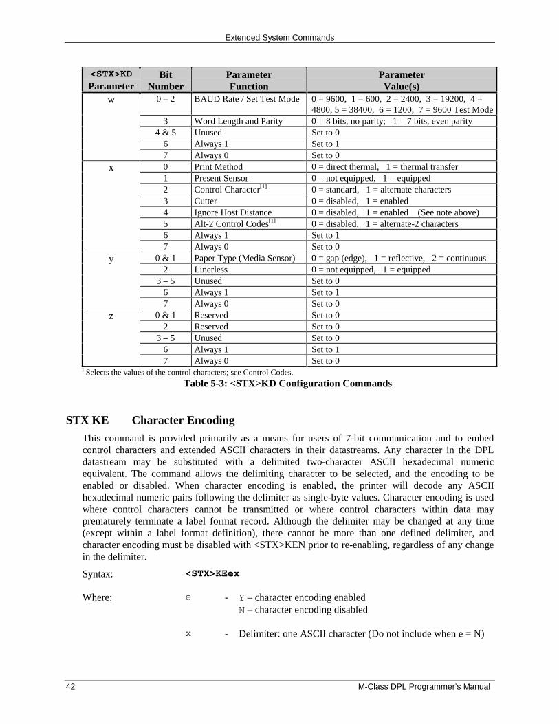
Extended System Commands
42 M-Class DPL Programmer’s Manual
<STX>KDParameter
BitNumber
ParameterFunction
ParameterValue(s)
0 – 2 BAUD Rate / Set Test Mode 0 = 9600, 1 = 600, 2 = 2400, 3 = 19200, 4 =4800, 5 = 38400, 6 = 1200, 7 = 9600 Test Mode
3 Word Length and Parity 0 = 8 bits, no parity; 1 = 7 bits, even parity4 & 5 Unused Set to 0
6 Always 1 Set to 1
w
7 Always 0 Set to 00 Print Method 0 = direct thermal, 1 = thermal transfer1 Present Sensor 0 = not equipped, 1 = equipped2 Control Character[1] 0 = standard, 1 = alternate characters3 Cutter 0 = disabled, 1 = enabled4 Ignore Host Distance 0 = disabled, 1 = enabled (See note above)5 Alt-2 Control Codes[1] 0 = disabled, 1 = alternate-2 characters6 Always 1 Set to 1
x
7 Always 0 Set to 00 & 1 Paper Type (Media Sensor) 0 = gap (edge), 1 = reflective, 2 = continuous
2 Linerless 0 = not equipped, 1 = equipped3 – 5 Unused Set to 0
6 Always 1 Set to 1
y
7 Always 0 Set to 00 & 1 Reserved Set to 0
2 Reserved Set to 03 – 5 Unused Set to 0
6 Always 1 Set to 1
z
7 Always 0 Set to 01 Selects the values of the control characters; see Control Codes.
Table 5-3: <STX>KD Configuration Commands
STX KE Character Encoding
This command is provided primarily as a means for users of 7-bit communication and to embedcontrol characters and extended ASCII characters in their datastreams. Any character in the DPLdatastream may be substituted with a delimited two-character ASCII hexadecimal numericequivalent. The command allows the delimiting character to be selected, and the encoding to beenabled or disabled. When character encoding is enabled, the printer will decode any ASCIIhexadecimal numeric pairs following the delimiter as single-byte values. Character encoding is usedwhere control characters cannot be transmitted or where control characters within data mayprematurely terminate a label format record. Although the delimiter may be changed at any time(except within a label format definition), there cannot be more than one defined delimiter, andcharacter encoding must be disabled with <STX>KEN prior to re-enabling, regardless of any changein the delimiter.
Syntax: <STX>KEex
Where: e - Y – character encoding enabledN – character encoding disabled
x - Delimiter: one ASCII character (Do not include when e = N)
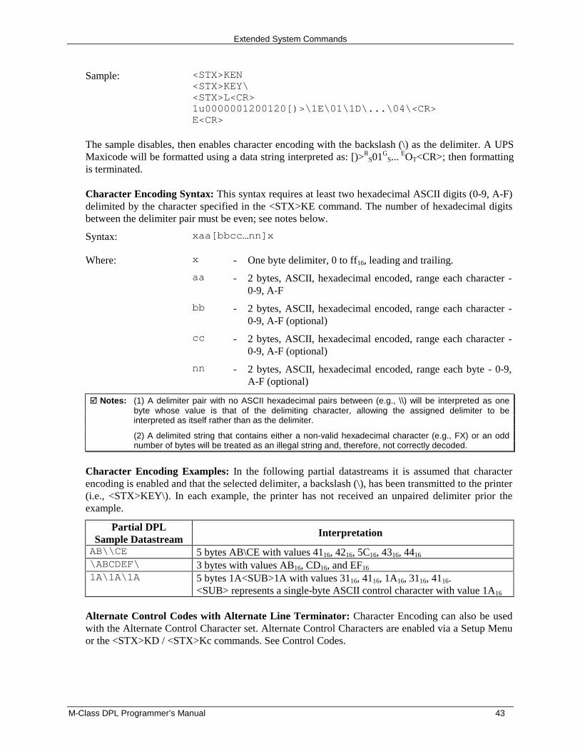
Extended System Commands
M-Class DPL Programmer’s Manual 43
Sample: <STX>KEN<STX>KEY\<STX>L<CR>1u0000001200120[)>\1E\01\1D\...\04\<CR>E<CR>
The sample disables, then enables character encoding with the backslash (\) as the delimiter. A UPSMaxicode will be formatted using a data string interpreted as: [)>R
S01GS...
EOT<CR>; then formattingis terminated.
Character Encoding Syntax: This syntax requires at least two hexadecimal ASCII digits (0-9, A-F)delimited by the character specified in the <STX>KE command. The number of hexadecimal digitsbetween the delimiter pair must be even; see notes below.
Syntax: xaa[bbcc…nn]x
Where: x - One byte delimiter, 0 to ff16, leading and trailing.
aa - 2 bytes, ASCII, hexadecimal encoded, range each character -0-9, A-F
bb - 2 bytes, ASCII, hexadecimal encoded, range each character -0-9, A-F (optional)
cc - 2 bytes, ASCII, hexadecimal encoded, range each character -0-9, A-F (optional)
nn - 2 bytes, ASCII, hexadecimal encoded, range each byte - 0-9,A-F (optional)
� Notes: (1) A delimiter pair with no ASCII hexadecimal pairs between (e.g., \\) will be interpreted as onebyte whose value is that of the delimiting character, allowing the assigned delimiter to beinterpreted as itself rather than as the delimiter.
(2) A delimited string that contains either a non-valid hexadecimal character (e.g., FX) or an oddnumber of bytes will be treated as an illegal string and, therefore, not correctly decoded.
Character Encoding Examples: In the following partial datastreams it is assumed that characterencoding is enabled and that the selected delimiter, a backslash (\), has been transmitted to the printer(i.e., <STX>KEY\). In each example, the printer has not received an unpaired delimiter prior theexample.
Partial DPLSample Datastream
Interpretation
AB\\CE 5 bytes AB\CE with values 4116, 4216, 5C16, 4316, 4416
\ABCDEF\ 3 bytes with values AB16, CD16, and EF16
1A\1A\1A 5 bytes 1A<SUB>1A with values 3116, 4116, 1A16, 3116, 4116.<SUB> represents a single-byte ASCII control character with value 1A16
Alternate Control Codes with Alternate Line Terminator: Character Encoding can also be usedwith the Alternate Control Character set. Alternate Control Characters are enabled via a Setup Menuor the <STX>KD / <STX>Kc commands. See Control Codes.
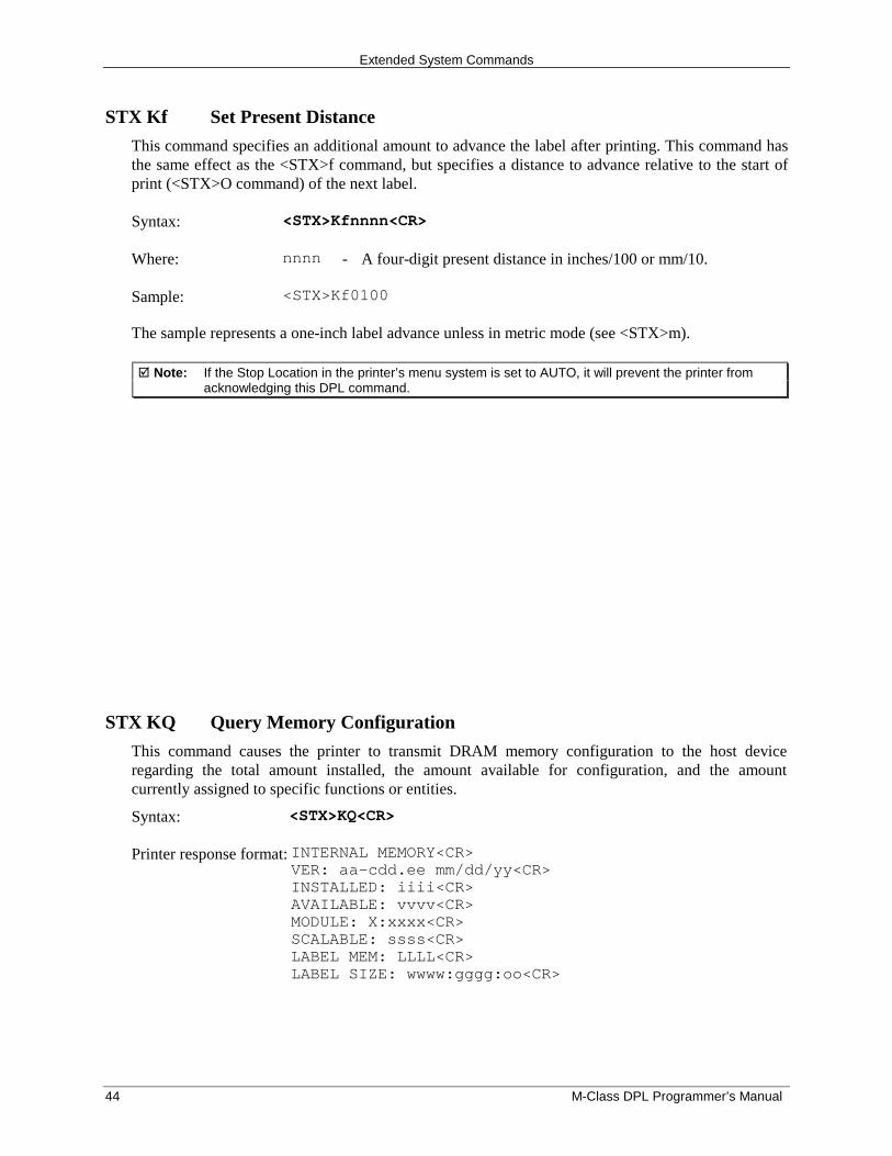
Extended System Commands
44 M-Class DPL Programmer’s Manual
STX Kf Set Present Distance
This command specifies an additional amount to advance the label after printing. This command hasthe same effect as the <STX>f command, but specifies a distance to advance relative to the start ofprint (<STX>O command) of the next label.
Syntax: <STX>Kfnnnn<CR>
Where: nnnn - A four-digit present distance in inches/100 or mm/10.
Sample: <STX>Kf0100
The sample represents a one-inch label advance unless in metric mode (see <STX>m).
� Note: If the Stop Location in the printer’s menu system is set to AUTO, it will prevent the printer fromacknowledging this DPL command.
STX KQ Query Memory Configuration
This command causes the printer to transmit DRAM memory configuration to the host deviceregarding the total amount installed, the amount available for configuration, and the amountcurrently assigned to specific functions or entities.
Syntax: <STX>KQ<CR>
Printer response format: INTERNAL MEMORY<CR>VER: aa-cdd.ee mm/dd/yy<CR>INSTALLED: iiii<CR>AVAILABLE: vvvv<CR>MODULE: X:xxxx<CR>SCALABLE: ssss<CR>LABEL MEM: LLLL<CR>LABEL SIZE: wwww:gggg:oo<CR>
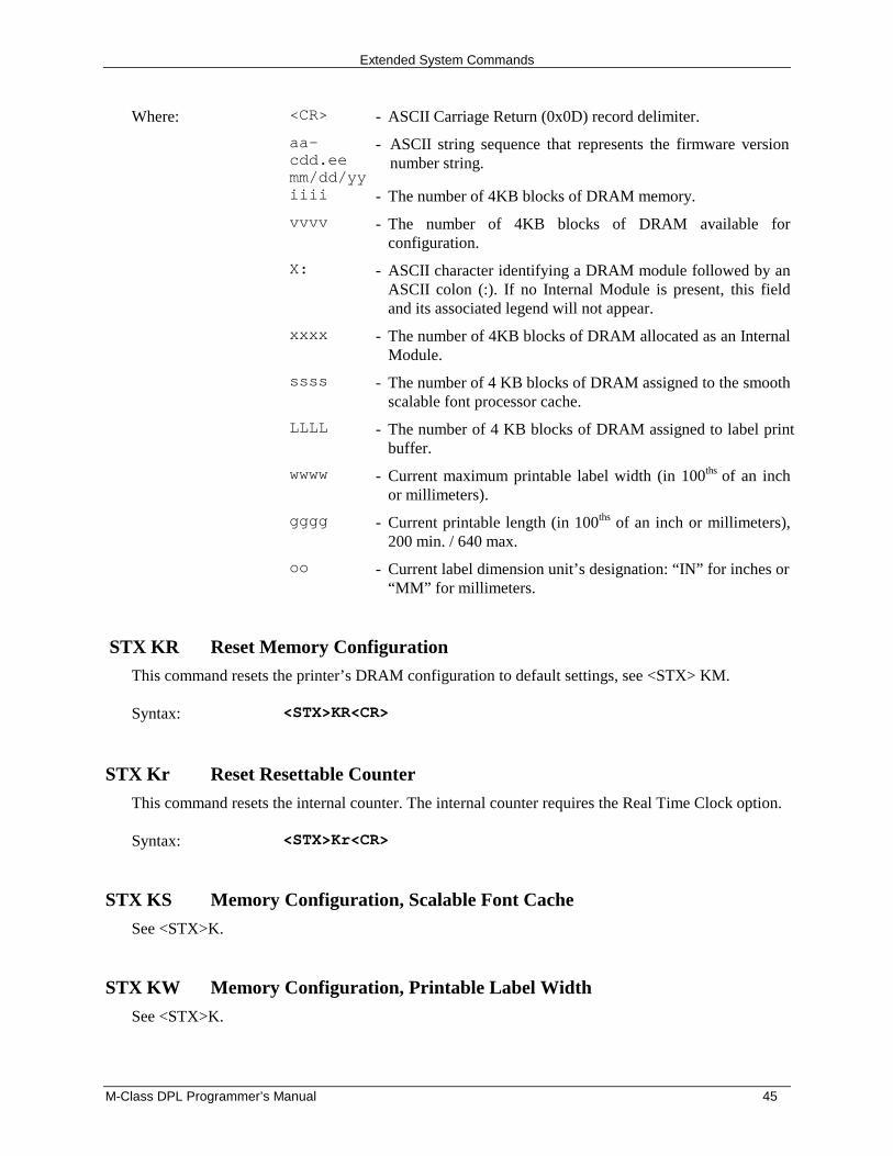
Extended System Commands
M-Class DPL Programmer’s Manual 45
Where: <CR> - ASCII Carriage Return (0x0D) record delimiter.
aa-cdd.eemm/dd/yy
- ASCII string sequence that represents the firmware versionnumber string.
iiii - The number of 4KB blocks of DRAM memory.
vvvv - The number of 4KB blocks of DRAM available forconfiguration.
X: - ASCII character identifying a DRAM module followed by anASCII colon (:). If no Internal Module is present, this fieldand its associated legend will not appear.
xxxx - The number of 4KB blocks of DRAM allocated as an InternalModule.
ssss - The number of 4 KB blocks of DRAM assigned to the smoothscalable font processor cache.
LLLL - The number of 4 KB blocks of DRAM assigned to label printbuffer.
wwww - Current maximum printable label width (in 100ths of an inchor millimeters).
gggg - Current printable length (in 100ths of an inch or millimeters),200 min. / 640 max.
oo - Current label dimension unit’s designation: “IN” for inches or“MM” for millimeters.
STX KR Reset Memory Configuration
This command resets the printer’s DRAM configuration to default settings, see <STX> KM.
Syntax: <STX>KR<CR>
STX Kr Reset Resettable Counter
This command resets the internal counter. The internal counter requires the Real Time Clock option.
Syntax: <STX>Kr<CR>
STX KS Memory Configuration, Scalable Font Cache
See <STX>K.
STX KW Memory Configuration, Printable Label Width
See <STX>K.

Extended System Commands
46 M-Class DPL Programmer’s Manual
M-Class DPL Programmer’s Manual 47
Label-Formatting Commands
IntroductionThe <STX>L command switches the printer from the System-Level Processor to the Label-FormattingProcessor. All commands following the <STX>L are interpreted as label-formatting commands, and canbe used to override default parameter values. Selectable parameter value defaults may be also reassignedvia the Setup Menu, as defined in the corresponding Operator’s Manual. Label formats that contain nocommands overriding printer default values will assume those defaults.
: Set Cut By Amount
This command allows a predetermined number of labels to be printed before a cut is initiated, auseful feature when it is necessary to print an uncut batch of labels. Between 1 and 9999 labels maybe printed before a cut is made. The amount must be smaller than the quantity of labels printed. Theprinter default is one.
Syntax: :nnnn
Where: nnnn - Is a four digit decimal number indicating the number of labels tobe printed before a cut is performed.
Sample: <STX>L<CR>:0005<CR>141100001000100SAMPLE LABEL<CR>Q0021<CR>E<CR>
The sample instructs the printer to make a cut after 5, 10, and 20 labels have been printed. Label 21will be cut at the start of a subsequent label format (batch) unless a default (cut by amount) greaterthan one has been entered.
� Note: The cutter must be enabled and all mechanism interlocks closed for the cut operation.
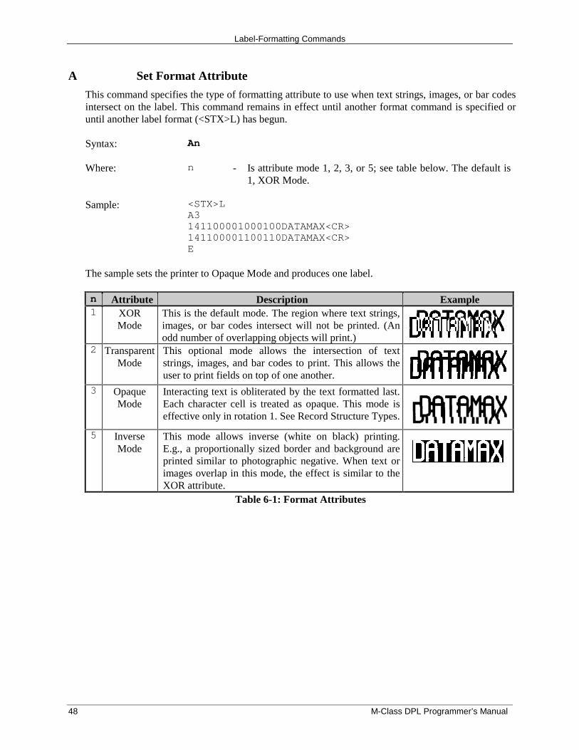
Label-Formatting Commands
48 M-Class DPL Programmer’s Manual
A Set Format Attribute
This command specifies the type of formatting attribute to use when text strings, images, or bar codesintersect on the label. This command remains in effect until another format command is specified oruntil another label format (<STX>L) has begun. Syntax: An
Where: n - Is attribute mode 1, 2, 3, or 5; see table below. The default is1, XOR Mode.
Sample: <STX>LA3141100001000100DATAMAX<CR>141100001100110DATAMAX<CR>E
The sample sets the printer to Opaque Mode and produces one label.
n Attribute Description Example1 XOR
ModeThis is the default mode. The region where text strings,images, or bar codes intersect will not be printed. (Anodd number of overlapping objects will print.)
2 TransparentMode
This optional mode allows the intersection of textstrings, images, and bar codes to print. This allows theuser to print fields on top of one another.
3 OpaqueMode
Interacting text is obliterated by the text formatted last.Each character cell is treated as opaque. This mode iseffective only in rotation 1. See Record Structure Types.
5 InverseMode
This mode allows inverse (white on black) printing.E.g., a proportionally sized border and background areprinted similar to photographic negative. When text orimages overlap in this mode, the effect is similar to theXOR attribute.
Table 6-1: Format Attributes
Extended System Commands
M-Class DPL Programmer’s Manual 49
C Set Column Offset Amount
This command allows horizontal adjustment of the point where printing begins. The printer isinstructed to print label formats nnnn units to the right of the position that the format specifies. Thisfeature is useful when a single format is to be printed on labels containing preprinted information.
� Note: If using preprinted labels where the placement of the preprint data varies from label to label, theprinted information may overlap the preprinted data.
Syntax: Cnnnn
Where: nnnn - Is a four-digit number (0000-9999) for the column offset, ininches /100 or mm/10. The printer default is 0.
Sample: <STX>LC0050141100001000100DATAMAX<CR>E
The sample prints a label shifted .5 inches to the right of the format, unless the printer is in metricmode.
c Set Cut By Amount
This command is the same as the Set Cut By Amount command (:); however, only a two-digit valuecan be entered. This allows a predetermined number of labels to be printed before a cut is performed.One to 99 labels may be printed before a cut is made.
Syntax: cnn
Where: nn - Is a two-digit number indicating the number of labels to be printedbefore performing a cut. The printer default is one.
Sample: <STX>L<CR>c07<CR>141100001000100SAMPLE LABEL<CR>Q0021<CR>E
The sample instructs the printer to make cuts after 7, 14, and 21 labels have been printed. See Label-Formatting Command ‘:’.
� Note: The cutter must be enabled and any mechanism interlocks closed for operation.
Label-Formatting Commands
50 M-Class DPL Programmer’s Manual
D Set Dot Size Width and Height
This command is used to change the size of the printed dots of the printhead (print resolution). Bychanging the height of the dots, the maximum length of a label can be increased or decreased. SeeAppendix J.
� Note: D22 is the default value for all printers.
Syntax: Dwh
Where: w - Is Dot Width multiplier 1 or 2.
h - Is Dot Height multiplier 1, 2, or 3.
E Terminate Label-Formatting Mode and Print
This command causes the printer, when the processing Label-Formatting commands, to terminate theLabel-Formatting Mode then generate, print, and feed a label. The label generated will be based onwhatever data has been received to that point, even if no printable data has been received. Othertermination commands are ‘X’ and ‘s’. Commands sent to the printer after the Terminate Labelcommand must be of the Immediate, System-Level, or Font Download type.
Syntax: E
Sample: <STX>L<CR>121100000000000Testing<CR>E<CR>
The sample label format will print one label.
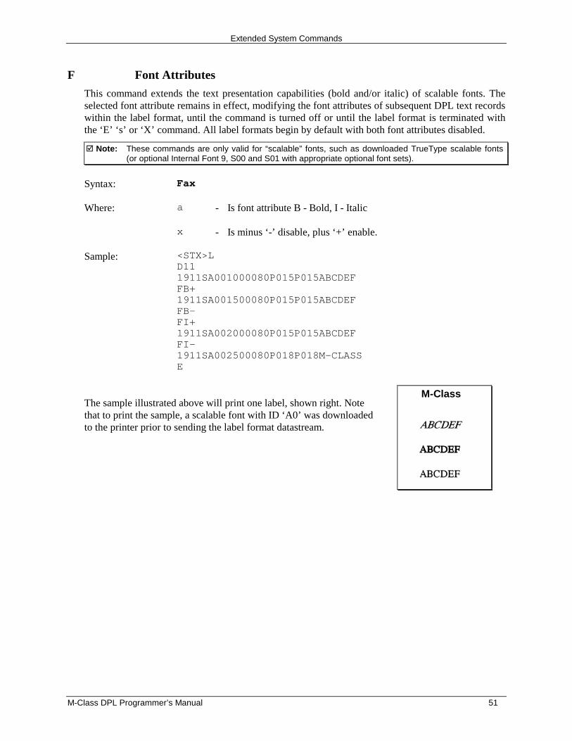
Extended System Commands
M-Class DPL Programmer’s Manual 51
F Font Attributes
This command extends the text presentation capabilities (bold and/or italic) of scalable fonts. Theselected font attribute remains in effect, modifying the font attributes of subsequent DPL text recordswithin the label format, until the command is turned off or until the label format is terminated withthe ‘E’ ‘s’ or ‘X’ command. All label formats begin by default with both font attributes disabled.
� Note: These commands are only valid for “scalable” fonts, such as downloaded TrueType scalable fonts(or optional Internal Font 9, S00 and S01 with appropriate optional font sets).
Syntax: Fax
Where: a - Is font attribute B - Bold, I - Italic
x - Is minus ‘-’ disable, plus ‘+’ enable.
Sample: <STX>LD111911SA001000080P015P015ABCDEFFB+1911SA001500080P015P015ABCDEFFB-FI+1911SA002000080P015P015ABCDEFFI-1911SA002500080P018P018M-CLASSE
The sample illustrated above will print one label, shown right. Notethat to print the sample, a scalable font with ID ‘A0’ was downloadedto the printer prior to sending the label format datastream.
M-Class
Label-Formatting Commands
52 M-Class DPL Programmer’s Manual
f Set Present Speed
This command controls the rate at which the present distance is positioned, allowing the mediamovement to be slowed during ‘presentation’ (the distance traveled after printing is completed to thelabel stop position). This command is used only within the context of a label format. The speedassigned is retained until another label format is received or until power is removed; if a subsequentformat does not contain a present speed command then the present speed reverts to the slew speed.
Syntax: fa
Where: a - Is a single alpha character representing a speed, limited by theslew speed range; see Appendix K. The default is the slew speed.
Sample: <STX>LD11H30PGSGfA191100200830165Fixed Data Field 1E<STX>L191100200830165Fixed Data Field 1E
The sample prints two labels; the first label has present speed of 1 inch per second, while the secondreverts to the slew speed of 4 inches per second.
G Place Data in Global Register
This command saves the print data of a print format record in a global register (temporary storage).This data can then be retrieved and copied to another record in the same label format using theSpecial Label-Formatting Command <STX>S. Global registers are named in the order received,beginning with A and ending at P; and are incremented with each instance of G command use.
Syntax: G
Sample: <STX>L<CR>121100000000000Testing<CR>G<CR>1A2210001000000<STX>SA<CR>E<CR>
The sample stores, retrieves and prints the data in global register A. One label is printed with“Testing” in two locations.
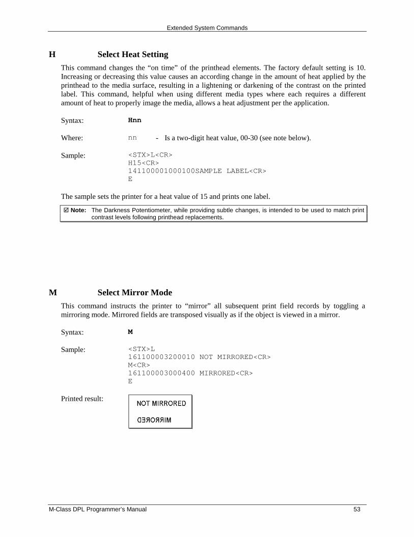
Extended System Commands
M-Class DPL Programmer’s Manual 53
H Select Heat Setting
This command changes the “on time” of the printhead elements. The factory default setting is 10.Increasing or decreasing this value causes an according change in the amount of heat applied by theprinthead to the media surface, resulting in a lightening or darkening of the contrast on the printedlabel. This command, helpful when using different media types where each requires a differentamount of heat to properly image the media, allows a heat adjustment per the application.
Syntax: Hnn
Where: nn - Is a two-digit heat value, 00-30 (see note below).
Sample: <STX>L<CR>H15<CR>141100001000100SAMPLE LABEL<CR>E
The sample sets the printer for a heat value of 15 and prints one label.
� Note: The Darkness Potentiometer, while providing subtle changes, is intended to be used to match printcontrast levels following printhead replacements.
M Select Mirror Mode
This command instructs the printer to “mirror” all subsequent print field records by toggling amirroring mode. Mirrored fields are transposed visually as if the object is viewed in a mirror.
Syntax: M
Sample: <STX>L161100003200010 NOT MIRRORED<CR>M<CR>161100003000400 MIRRORED<CR>E
Printed result:
Label-Formatting Commands
54 M-Class DPL Programmer’s Manual
m Set Metric Mode
This command sets the printer to measure in metric-based units (e.g., a column offset of 0010 will beinterpreted as 1.0 mm). All printers default to imperial (inch) mode.
Syntax: m
Sample: <STX>L<CR>m141100001000100SAMPLE LABEL<CR>E
The sample prints the text (SAMPLE LABEL) starting at location coordinates 10.0 mm, 10.0 mm.
n Set Imperial (Inch) Mode
This command sets the printer to measure in inch-based units. All printers default to imperial units.
Syntax: n
Sample: <STX>L<CR>n141100001000100SAMPLE LABEL<CR>E
The sample prints the text (SAMPLE LABEL) starting at location coordinates 1.0 inch, 1.0 inch.
P Set Print Speed
This command controls the rate at which label printing is performed.
Syntax: Pa
Where: a - Is a single alpha character representing a speed; see Appendix Kfor valid ranges.
Sample: <STX>LPC141100001000100LABEL1<CR>E<STX>L141100001000100LABEL2>CR>E
The sample produces two labels, the first at a print speed of 2 inches per second and the second atthe printer default.
Extended System Commands
M-Class DPL Programmer’s Manual 55
p Set Backfeed Speed
This command, typically used in conjunction with the Cut or Peel and Present operations, controlsthe rate at which the labels will reverse to align to the next start of print position. The setting remainsin effect until another backfeed speed command is received or until the printer is reset.
Syntax: pa
Where: a - Is a single alpha character representing a speed; see Appendix Kfor valid ranges.
Sample: <STX>LpF
The above sample sets the printer to backfeed at 3.5 inches per second.
Q Set Print Quantity
This command sets the number of the label copies to be printed. A one to five digit value is allowed,if the command is delimited by a carriage return <CR>. This permits host applications to generatelabel quantity commands without the need to pad leading zeros. (A four-digit command value doesnot need to be <CR> terminated.)
Syntax: Qnnnnn
Where: nnnnn - Is a one to five-digit delimited value setting for the number oflabels to be printed. The default value is one.
Sample: <STX>L121100000000000Testing<CR>Q20<CR>E<CR>
The above sample will print a batch of 20 identical labels.
Label-Formatting Commands
56 M-Class DPL Programmer’s Manual
R Set Row Offset Amount
This command allows vertical adjustment of the point where printing begins. The printer is instructedto print label formats nnnn units above the position that the format specifies. This feature is usefulwhen a single format is to be printed on labels containing preprinted information.
� Note: If using preprinted labels where the placement of the preprint data varies from label to label, theprinted information may overlap the preprinted data.
Syntax: Rnnnn
Where: nnnn - Is a four-digit number (0000-9999) for the row offset, ininches/100 or millimeters/10. The printer default is 0.
Sample: <STX>LR0037<CR>141100001000100SAMPLE LABEL<CR>E
The sample prints a label with a row offset amount of .37 of an inch, unless in metric mode.
r Recall Stored Label Format
This command is used to retrieve label formats stored on a memory module.
Syntax: rnn…n
Where: nn…n - Is the label name, up to 16 characters in length.
The samples below explain different ways to recall and print a label format. (To view a memorymodule’s directory of label formats use the <STX>W command.)
String Sent: Printer Interpretation:
Sample 1: <STX>L<CR>rTEST<CR>Q0002<CR>E<CR>
Begin label formatRetrieve format named TESTQuantity requested = 2Terminate formatting and print
Sample 2: <STX>L<CR>rTEST<CR>X<CR><STX>G<CR>
Begin label formatRetrieve format named testTerminate formattingPrint
Sample 3: <STX>L<CR>D11<CR>PO<CR>SO<CR>rTEST<CR>E<CR>
Begin label formatDot size = 1x1Print speed 0Slew speed 0Retrieve format named testTerminate formatting and print
Extended System Commands
M-Class DPL Programmer’s Manual 57
S Set Slew Speed
This command controls the rate at which the label is moved through non-printed areas. The settingremains unchanged unless another slew speed command is received or until the printer is reset.
Syntax: Sa
Where: a - Is a single alpha character representing a speed; see Appendix Kfor valid ranges.
Sample: <STX>LSE141100001000100LABEL1<CR>E<STX>L1411000010001000LABEL2<CR>E
The sample sets the slew speed to 3 inches per second (76 mmps), and prints two labels. The slewspeed for the second label is the same as the first.
s Store Label Format In Module
This command stores a label format to a specified module. Supplying the module name (seeAppendix J for valid designators) will store the label to that module; otherwise, using C will causethe label format to be stored in the selected default module (see <STX>X.). In addition, thiscommand terminates the Label-Formatting Command.
Syntax: Sann…n
Where: a - Is the module designator representing a single character modulename; see Appendix J.
nn…n - Represents the name of the label (maximum 16 characters).
Sample: <STX>L<CR>D11<CR>191100501000000123456789012<CR>1911005020000001234567<CR>191100500000000Sample<CR>1X1100000000000B250250002002<CR>Q0001<CR>sATEST<CR>
The example stores a format in memory module A and names it ‘TEST’. (To recall a label formatfrom the module use the ‘r’ command.)
� Note: When storing a label for Line Mode the name must be "DMXFRM” or “DMXFRMXX” where XX is anyalphanumeric. See Appendix B for more detail.
Label-Formatting Commands
58 M-Class DPL Programmer’s Manual
T Set Field Data Line Terminator
This command, intended for use with record types that accept binary data (e.g., PDF417), allowsspecial binary control codes (e.g., a carriage return) to be embedded in the printed data by setting analternate data line terminator. It remains valid only for the next format record, then resumes thedefault value. See Alternate Control Code Mode.
Syntax: Tnn
Where: nn - Is an ASCII two-character representation of a HEX code to be usedfor the end of data terminator.
Sample: <STX>L<CR>T00<CR>191100200000000TEST<NULL>141100001000100TERMINATOR<CR>Q0001<CR>E<CR>
The sample sets the printer to use a NULL terminator (ASCII NULL: HEX 00) for the data linetermination code. The terminator is immediately restored to a carriage return <CR>, as seen in theformat record containing the text ‘TERMINATOR’.
U Mark Previous Field as a String Replacement Field
This command controls the way replacement data is formatted. Specifying a field as a stringreplacement for dynamic fields, and not for static fields, will optimize label throughput. See the<STX>U command.
� Note: The data string length of any replacement is set by the length of the original string; both mustbe equal. The data being used when created must be valid for the font type being selected.
Syntax: U
Sample: <STX>LD11121100001000000123456789012<CR>U<CR>1211000020000001234567<CR>U<CR>161100000000000Sample<CR>1X1100000000000B250250002002<CR>Q0001E<STX>U01ABCDEFGHIJKL<CR><STX>U028901234<CR><STX>G
Extended System Commands
M-Class DPL Programmer’s Manual 59
The sample sets up the label format for register loading and prints two labels. The first two of thefour format records have been designated as replacement fields. The second label is generated withSystem-Level field-replacement commands and prints the last label.
� Note: The data string length of any register is set by the length of the string when it was created and thenew string must be the same length as the old string. The data being used when it is created must bevalid for the font type being used.
X Terminate Label-Formatting Mode without Printing
This command causes the printer, when in label-formatting mode, to immediately switch to thesystem command mode and generate a label format based on the data received at that point.However, unlike the ‘E’ command, it will not print a label. (Other termination commands are the ‘E’and ‘s’.)
Syntax: X
Sample: <STX>L<CR>141100001000100SAMPLE<CR>X<CR>
The sample will result in a label format, but no label will be printed.
y Select Font Symbol Set
This command, like the <STX>y, selects the scalable font symbol set. The selected symbol setremains active until another symbol set is selected; see the <STX>y for details.
Syntax: ySxx
Where: S - Byte size designation; see Appendix HS = Single-byte symbol sets.U = Double-byte symbol sets (as equipped)
xx - Symbol set selection.
Sample: <STX>LySSW<CR>
The sample selects the Swedish symbol set for use in succeeding format records using scalable fonts.
Label-Formatting Commands
60 M-Class DPL Programmer’s Manual
z Zero (Ø) Conversion to “0”
This command removes the slash zero in fonts 0 to 8, and in the human readable field (if any) of thebar codes A to Z. The command applies only to format records containing those fonts and bar codes,and is effective only for the label format in which it appears.
� Note: None of the smooth fonts (i.e., font 9) has the slash zero; also, this command will have no effect onscalable fonts.
Syntax: z
Sample: <STX>Lz121100000000000Test0000<CR>E
+ (>) Make Last Field Entered Increment Numeric (Alphanumeric)
This command, useful in printing sequenced labels, causes the printer to automatically increment afield on the labels in a batch. The numeric data in the field will increment by the value assigned afterthe plus sign (+) each time a label is produced (or the greater than character [>] can be substituted tomake the field increment alphabetically). This command is effective only on the label format recordthat it follows, and is intended to be used with the Q, <STX>E or <STX>G commands.
Syntax: *pii
Where: * - Is + for numeric increment, or > for alphanumeric increment.
p - Is the fill character for the leftmost character of the field.
ii - Is the amount to increment the field.
Sample: <STX>L<CR>13220000000000012345<CR>+01<CR>Q0003<CR>E<CR>
The sample will generate a single field label format that prints the initial label with a value of 12345,and then increments that number by one for the next two labels.
Embedding
Numeric strings for incrementing may also be embedded between alphabetic characters (e.g., whensystems require alphanumeric barcodes with alphabetic prefixes or suffixes).
Extended System Commands
M-Class DPL Programmer’s Manual 61
Sample: <STX>L<CR>161100000100010AB0001CD<CR>+100<CR>Q0003<CR>E<CR>
The sample will print three labels, incrementing 0001 by 1 on each label with AB and CD remaininguntouched: AB0001CD, AB0002CD, AB0003CD. Note that the increment value has one leadingblank and two trailing zeros; the blank is a pad character with no consequences in this example, andthe trailing zeroes are placeholders which leave CD unchanged.
- (<) Make Last Field Entered Decrement Numeric (Alphanumeric)
This command, useful in printing sequenced labels, causes the printer to automatically decrement afield on the labels in a batch. The numeric data in the field will decrement by the value assigned afterthe minus (-) sign each time a label is produced (or the less than character [<] can be substituted tomake the field decrement alphabetically). This command is effective only on the label format recordthat it follows, and is intended to be used with the Q, <STX>E or <STX>G commands.
Syntax: *pii
Where: * - Is - for numeric decrement, or < for alphanumeric decrement.
p - Is the fill character for the leftmost character of the field.
ii - Is the amount by which to decrement the field.
Sample: <STX>L<CR>132200000000000123AB<CR><01<CR>Q0003<CR>E<CR>
The sample will generate a single field label format that prints the initial label with a value of123AB, and then decrements that number by one for the next two labels.
Embedding
Numeric strings for decrementing may also be embedded between alphabetic characters (e.g., whensystems require alphanumeric barcodes with alphabetic prefixes or suffixes).
Sample: <STX>L<CR>1611000001000101000CD<CR>-100<CR>Q0003<CR>E<CR>
The sample will print three labels: 1000CD, 999CD, and 998CD. Note that the pad character is aplaceholder for digits removed from the left side in the subtraction process. When a fixed pitch font(where all characters have the same width) is used, the justification of the rightmost character issustained regardless of the number of digits replaced by the pad character on the left side.
Label-Formatting Commands
62 M-Class DPL Programmer’s Manual
^ Set Count by Amount
This command allows applications using the increment / decrement field command to print more thanone label with the same field value before the field data is updated. All printers default to 1.
� Note: This command can only be issued once per label format. In addition, when alternate ControlCodes are enabled, the ^ character must be replaced by the @ character (hexadecimal 0x40). SeeControl Codes.
Syntax: ^nn
Where: ^ - May be 0x55 or 0x40, see Control Codes.
nn - Is a two-digit value that specifies the number of labels to begenerated before incrementing (or decrementing) the field value.
Sample: <STX>L<CR>13220000000000012345<CR>-01<CR>^02<CR>Q0006<CR>E<CR>
The sample prints two labels containing the same field value before decrementing the field. Sixlabels are printed.
Special Label-Formatting CommandsTwo Special Label-Formatting Commands, the <STX> S and the <STX> T, are entered directly into thedata field of label format records. Do not confuse them with System-Level Commands because the samecontrol character is used. If alternate control codes are enabled the <STX> becomes ‘~’ (hexadecimal0x7E); see Control Codes.
Label-Formatting Character Command Description<STX>S Recall global data and place in field<STX>T Print time and date
Table 6-2: Special Label-Formatting Commands
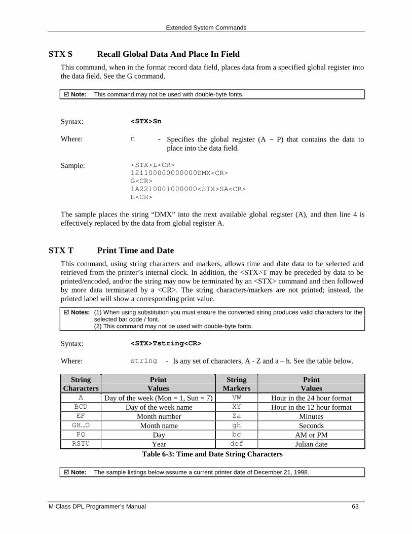
Extended System Commands
M-Class DPL Programmer’s Manual 63
STX S Recall Global Data And Place In Field
This command, when in the format record data field, places data from a specified global register intothe data field. See the G command.
� Note: This command may not be used with double-byte fonts.
Syntax: <STX>Sn
Where: n - Specifies the global register (A − P) that contains the data toplace into the data field.
Sample: <STX>L<CR>121100000000000DMX<CR>G<CR>1A2210001000000<STX>SA<CR>E<CR>
The sample places the string “DMX” into the next available global register (A), and then line 4 iseffectively replaced by the data from global register A.
STX T Print Time and Date
This command, using string characters and markers, allows time and date data to be selected andretrieved from the printer’s internal clock. In addition, the <STX>T may be preceded by data to beprinted/encoded, and/or the string may now be terminated by an <STX> command and then followedby more data terminated by a <CR>. The string characters/markers are not printed; instead, theprinted label will show a corresponding print value.
� Notes: (1) When using substitution you must ensure the converted string produces valid characters for theselected bar code / font.(2) This command may not be used with double-byte fonts.
Syntax: <STX>Tstring<CR>
Where: string - Is any set of characters, A - Z and a – h. See the table below.
StringCharacters
PrintValues
StringMarkers
PrintValues
A Day of the week (Mon = 1, Sun = 7) VW Hour in the 24 hour formatBCD Day of the week name XY Hour in the 12 hour formatEF Month number Za MinutesGH…O Month name gh SecondsPQ Day bc AM or PMRSTU Year def Julian date
Table 6-3: Time and Date String Characters
� Note: The sample listings below assume a current printer date of December 21, 1998.
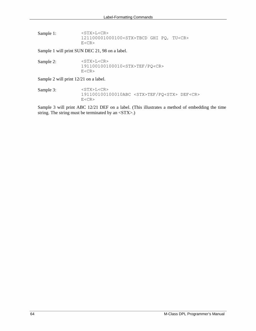
Label-Formatting Commands
64 M-Class DPL Programmer’s Manual
Sample 1: <STX>L<CR>121100001000100<STX>TBCD GHI PQ, TU<CR>E<CR>
Sample 1 will print SUN DEC 21, 98 on a label.
Sample 2: <STX>L<CR>191100100100010<STX>TEF/PQ<CR>E<CR>
Sample 2 will print 12/21 on a label.
Sample 3: <STX>L<CR>191100100100010ABC <STX>TEF/PQ<STX> DEF<CR>E<CR>
Sample 3 will print ABC 12/21 DEF on a label. (This illustrates a method of embedding the timestring. The string must be terminated by an <STX>.)
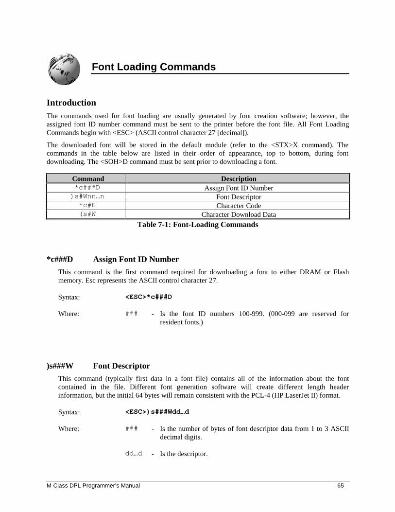
M-Class DPL Programmer’s Manual 65
Font Loading Commands
IntroductionThe commands used for font loading are usually generated by font creation software; however, theassigned font ID number command must be sent to the printer before the font file. All Font LoadingCommands begin with <ESC> (ASCII control character 27 [decimal]).
The downloaded font will be stored in the default module (refer to the <STX>X command). Thecommands in the table below are listed in their order of appearance, top to bottom, during fontdownloading. The <SOH>D command must be sent prior to downloading a font.
Command Description*c###D Assign Font ID Number)s#Wnn…n Font Descriptor*c#E Character Code(s#W Character Download Data
Table 7-1: Font-Loading Commands
*c###D Assign Font ID Number
This command is the first command required for downloading a font to either DRAM or Flashmemory. Esc represents the ASCII control character 27.
Syntax: <ESC>*c###D
Where: ### - Is the font ID numbers 100-999. (000-099 are reserved forresident fonts.)
)s###W Font Descriptor
This command (typically first data in a font file) contains all of the information about the fontcontained in the file. Different font generation software will create different length headerinformation, but the initial 64 bytes will remain consistent with the PCL-4 (HP LaserJet II) format.
Syntax: <ESC>)s###Wdd…d
Where: ### - Is the number of bytes of font descriptor data from 1 to 3 ASCIIdecimal digits.
dd…d - Is the descriptor.
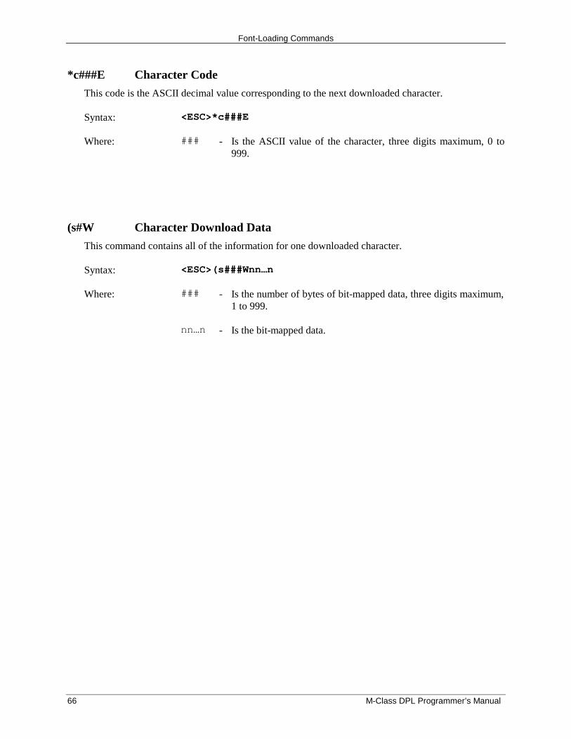
Font-Loading Commands
66 M-Class DPL Programmer’s Manual
*c###E Character Code
This code is the ASCII decimal value corresponding to the next downloaded character.
Syntax: <ESC>*c###E
Where: ### - Is the ASCII value of the character, three digits maximum, 0 to999.
(s#W Character Download Data
This command contains all of the information for one downloaded character.
Syntax: <ESC>(s###Wnn…n
Where: ### - Is the number of bytes of bit-mapped data, three digits maximum,1 to 999.
nn…n - Is the bit-mapped data.
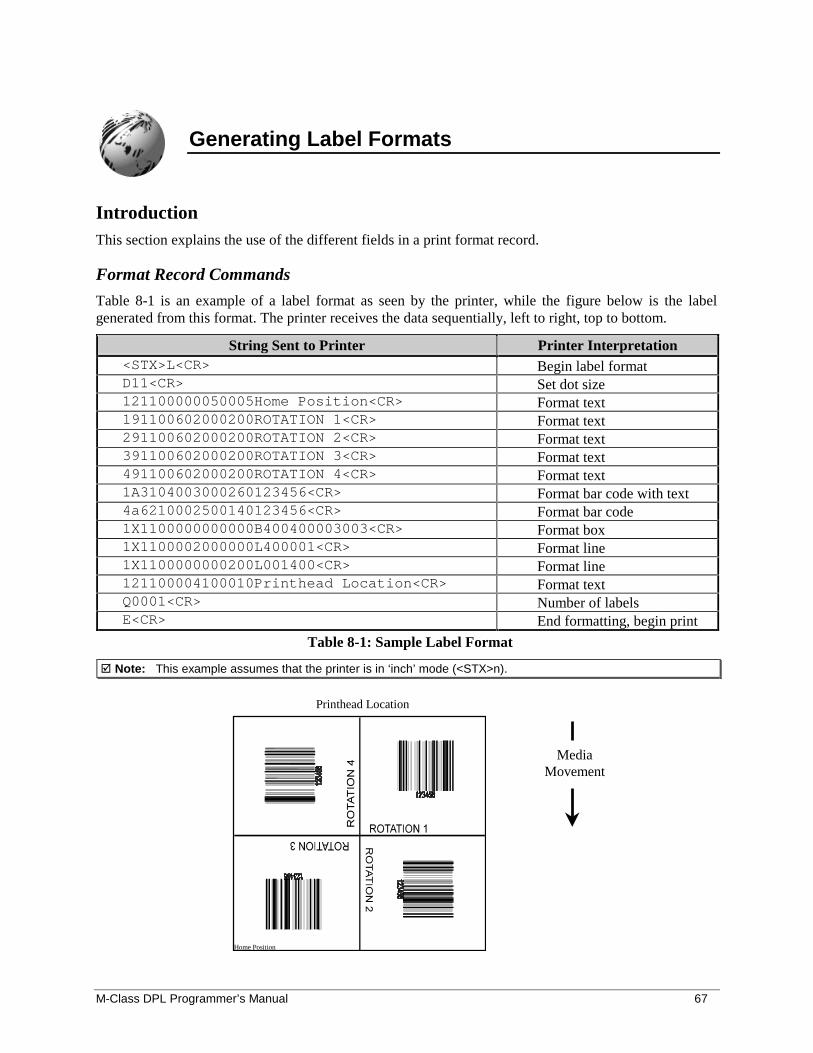
M-Class DPL Programmer’s Manual 67
Generating Label Formats
IntroductionThis section explains the use of the different fields in a print format record.
Format Record Commands
Table 8-1 is an example of a label format as seen by the printer, while the figure below is the labelgenerated from this format. The printer receives the data sequentially, left to right, top to bottom.
String Sent to Printer Printer Interpretation<STX>L<CR> Begin label formatD11<CR> Set dot size121100000050005Home Position<CR> Format text191100602000200ROTATION 1<CR> Format text291100602000200ROTATION 2<CR> Format text391100602000200ROTATION 3<CR> Format text491100602000200ROTATION 4<CR> Format text1A3104003000260123456<CR> Format bar code with text4a6210002500140123456<CR> Format bar code1X1100000000000B400400003003<CR> Format box1X1100002000000L400001<CR> Format line1X1100000000200L001400<CR> Format line121100004100010Printhead Location<CR> Format textQ0001<CR> Number of labelsE<CR> End formatting, begin print
Table 8-1: Sample Label Format
� Note: This example assumes that the printer is in ‘inch’ mode (<STX>n).
Printhead Location
Home Position
MediaMovement
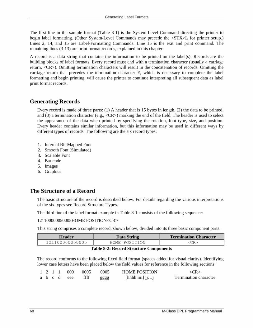
Generating Label Formats
68 M-Class DPL Programmer’s Manual
The first line in the sample format (Table 8-1) is the System-Level Command directing the printer tobegin label formatting. (Other System-Level Commands may precede the <STX>L for printer setup.)Lines 2, 14, and 15 are Label-Formatting Commands. Line 15 is the exit and print command. Theremaining lines (3-13) are print format records, explained in this chapter.
A record is a data string that contains the information to be printed on the label(s). Records are thebuilding blocks of label formats. Every record must end with a termination character (usually a carriagereturn, <CR>). Omitting termination characters will result in the concatenation of records. Omitting thecarriage return that precedes the termination character E, which is necessary to complete the labelformatting and begin printing, will cause the printer to continue interpreting all subsequent data as labelprint format records.
Generating RecordsEvery record is made of three parts: (1) A header that is 15 bytes in length, (2) the data to be printed,and (3) a termination character (e.g., <CR>) marking the end of the field. The header is used to selectthe appearance of the data when printed by specifying the rotation, font type, size, and position.Every header contains similar information, but this information may be used in different ways bydifferent types of records. The following are the six record types:
1. Internal Bit-Mapped Font2. Smooth Font (Simulated)3. Scalable Font4. Bar code5. Images6. Graphics
The Structure of a RecordThe basic structure of the record is described below. For details regarding the various interpretationsof the six types see Record Structure Types.
The third line of the label format example in Table 8-1 consists of the following sequence:
121100000050005HOME POSITION<CR>
This string comprises a complete record, shown below, divided into its three basic component parts.
Header Data String Termination Character121100000050005 HOME POSITION <CR>
Table 8-2: Record Structure Components
The record conforms to the following fixed field format (spaces added for visual clarity). Identifyinglower case letters have been placed below the field values for reference in the following sections:
1 2 1 1 000 0005 0005 <CR>a b c d eee ffff gggg
HOME POSITION[hhhh iiii] jj…j Termination character
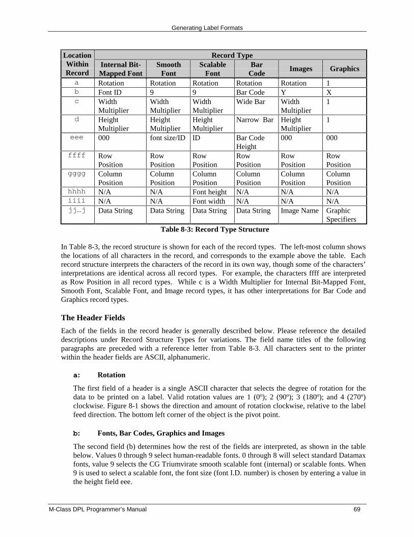
Generating Label Formats
M-Class DPL Programmer’s Manual 69
Record TypeLocationWithinRecord
Internal Bit-Mapped Font
SmoothFont
ScalableFont
BarCode
Images Graphics
a Rotation Rotation Rotation Rotation Rotation 1b Font ID 9 9 Bar Code Y Xc Width
MultiplierWidthMultiplier
WidthMultiplier
Wide Bar WidthMultiplier
1
d HeightMultiplier
HeightMultiplier
HeightMultiplier
Narrow Bar HeightMultiplier
1
eee 000 font size/ID ID Bar CodeHeight
000 000
ffff RowPosition
RowPosition
RowPosition
RowPosition
RowPosition
RowPosition
gggg ColumnPosition
ColumnPosition
ColumnPosition
ColumnPosition
ColumnPosition
ColumnPosition
hhhh N/A N/A Font height N/A N/A N/Aiiii N/A N/A Font width N/A N/A N/Ajj…j Data String Data String Data String Data String Image Name Graphic
SpecifiersTable 8-3: Record Type Structure
In Table 8-3, the record structure is shown for each of the record types. The left-most column showsthe locations of all characters in the record, and corresponds to the example above the table. Eachrecord structure interprets the characters of the record in its own way, though some of the characters’interpretations are identical across all record types. For example, the characters ffff are interpretedas Row Position in all record types. While c is a Width Multiplier for Internal Bit-Mapped Font,Smooth Font, Scalable Font, and Image record types, it has other interpretations for Bar Code andGraphics record types.
The Header Fields
Each of the fields in the record header is generally described below. Please reference the detaileddescriptions under Record Structure Types for variations. The field name titles of the followingparagraphs are preceded with a reference letter from Table 8-3. All characters sent to the printerwithin the header fields are ASCII, alphanumeric.
a: Rotation
The first field of a header is a single ASCII character that selects the degree of rotation for thedata to be printed on a label. Valid rotation values are 1 (0º); 2 (90º); 3 (180º); and 4 (270º)clockwise. Figure 8-1 shows the direction and amount of rotation clockwise, relative to the labelfeed direction. The bottom left corner of the object is the pivot point.
b: Fonts, Bar Codes, Graphics and Images
The second field (b) determines how the rest of the fields are interpreted, as shown in the tablebelow. Values 0 through 9 select human-readable fonts. 0 through 8 will select standard Datamaxfonts, value 9 selects the CG Triumvirate smooth scalable font (internal) or scalable fonts. When9 is used to select a scalable font, the font size (font I.D. number) is chosen by entering a value inthe height field eee.
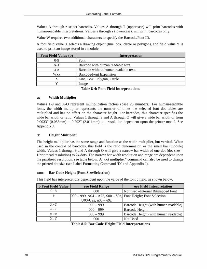
Generating Label Formats
70 M-Class DPL Programmer’s Manual
Values A through z select barcodes. Values A through T (uppercase) will print barcodes withhuman-readable interpretations. Values a through z (lowercase), will print barcodes only.
Value W requires two additional characters to specify the Barcode/Font ID.
A font field value X selects a drawing object (line, box, circle or polygon), and field value Y isused to print an image stored in a module.
Font Field Value (b) Interpretation0-9 FontA-T Barcode with human readable text.a-z Barcode without human readable text.
Wxx Barcode/Font ExpansionX Line, Box, Polygon, CircleY Image
Table 8-4: Font Field Interpretations
c: Width Multiplier
Values 1-9 and A-O represent multiplication factors (base 25 numbers). For human-readablefonts, the width multiplier represents the number of times the selected font dot tables aremultiplied and has no effect on the character height. For barcodes, this character specifies thewide bar width or ratio. Values 1 through 9 and A through O will give a wide bar width of from0.0033” (0.085mm) to 0.792” (2.011mm) at a resolution dependent upon the printer model. SeeAppendix J.
d: Height Multiplier
The height multiplier has the same range and function as the width multiplier, but vertical. Whenused in the context of barcodes, this field is the ratio denominator, or the small bar (module)width. Values 1 through 9 and A through O will give a narrow bar width of one dot (dot size =1/printhead resolution) to 24 dots. The narrow bar width resolution and range are dependent uponthe printhead resolution, see table below. A “dot multiplier” command can also be used to changethe printed dot size (see Label-Formatting Command ‘D’ and Appendix J).
eee: Bar Code Height (Font Size/Selection)
This field has interpretations dependent upon the value of the font b field, as shown below.
b Font Field Value eee Field Range eee Field Interpretation0-8 000 Not used –Internal Bitmapped Font9 000 – 999, A04 – A72, S00 – S9z,
U00-U9z, u00 – u9zFont Height; Font Selection
A-T 000 – 999 Barcode Height (with human readable)a-z 000 – 999 Barcode HeightWxx 000 – 999 Barcode Height (with human readable)X,Y 000 Not Used
Table 8-5: Bar Code Height Field Interpretations
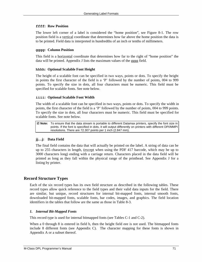
Generating Label Formats
M-Class DPL Programmer’s Manual 71
ffff: Row Position
The lower left corner of a label is considered the “home position”, see Figure 8-1. The rowposition field is a vertical coordinate that determines how far above the home position the data isto be printed. Field data is interpreted in hundredths of an inch or tenths of millimeters.
gggg: Column Position
This field is a horizontal coordinate that determines how far to the right of “home position” thedata will be printed. Appendix J lists the maximum values of the gggg field.
hhhh: Optional Scalable Font Height
The height of a scalable font can be specified in two ways, points or dots. To specify the heightin points the first character of the field is a ‘P’ followed by the number of points, 004 to 999points. To specify the size in dots, all four characters must be numeric. This field must bespecified for scalable fonts. See note below.
iiii: Optional Scalable Font Width
The width of a scalable font can be specified in two ways, points or dots. To specify the width inpoints, the first character of the field is a ‘P’ followed by the number of points, 004 to 999 points.To specify the size in dots, all four characters must be numeric. This field must be specified forscalable fonts. See note below.
� Note: To ensure that the data stream is portable to different Datamax printers, specify the font size inpoints. If the font is specified in dots, it will output differently on printers with different DPI/MMPIresolutions. There are 72.307 points per 1 inch (2.847 mm).
jj…j: Data Field
The final field contains the data that will actually be printed on the label. A string of data can beup to 255 characters in length, (except when using the PDF 417 barcode, which may be up to3000 characters long) ending with a carriage return. Characters placed in the data field will beprinted as long as they fall within the physical range of the printhead. See Appendix J for alisting by printer.
Record Structure Types
Each of the six record types has its own field structure as described in the following tables. Theserecord types allow quick reference to the field types and their valid data inputs for the field. Thereare similar, but unique, record structures for internal bit-mapped fonts, internal smooth fonts,downloaded bit-mapped fonts, scalable fonts, bar codes, images, and graphics. The field locationidentifiers in the tables that follow are the same as those in Table 8-3.
1. Internal Bit-Mapped Fonts
This record type is used for internal bitmapped fonts (see Tables C-1 and C-2).
When a 0 through 8 is entered in field b, then the height field eee is not used. The bitmapped fontsinclude 8 different fonts (see Appendix C). The character mapping for these fonts is shown inAppendix A or a subset thereof.
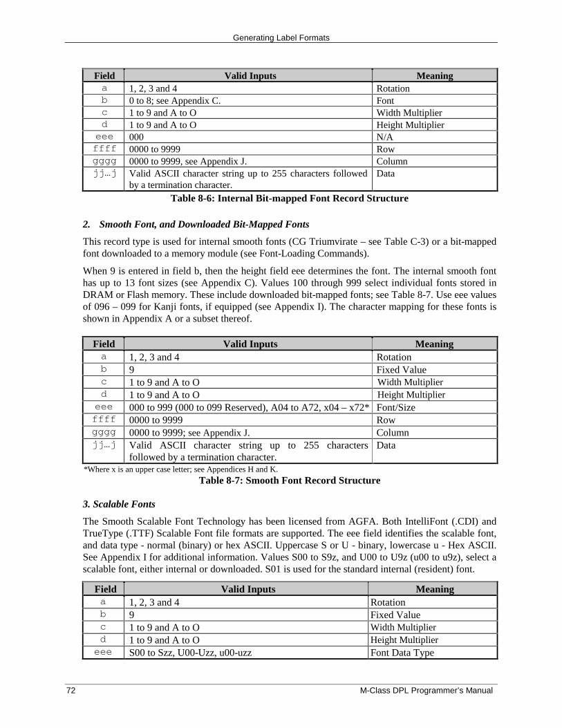
Generating Label Formats
72 M-Class DPL Programmer’s Manual
Field Valid Inputs Meaninga 1, 2, 3 and 4 Rotationb 0 to 8; see Appendix C. Fontc 1 to 9 and A to O Width Multiplierd 1 to 9 and A to O Height Multipliereee 000 N/Affff 0000 to 9999 Rowgggg 0000 to 9999, see Appendix J. Columnjj…j Valid ASCII character string up to 255 characters followed
by a termination character.Data
Table 8-6: Internal Bit-mapped Font Record Structure
2. Smooth Font, and Downloaded Bit-Mapped Fonts
This record type is used for internal smooth fonts (CG Triumvirate – see Table C-3) or a bit-mappedfont downloaded to a memory module (see Font-Loading Commands).
When 9 is entered in field b, then the height field eee determines the font. The internal smooth fonthas up to 13 font sizes (see Appendix C). Values 100 through 999 select individual fonts stored inDRAM or Flash memory. These include downloaded bit-mapped fonts; see Table 8-7. Use eee valuesof 096 – 099 for Kanji fonts, if equipped (see Appendix I). The character mapping for these fonts isshown in Appendix A or a subset thereof.
Field Valid Inputs Meaninga 1, 2, 3 and 4 Rotationb 9 Fixed Valuec 1 to 9 and A to O Width Multiplierd 1 to 9 and A to O Height Multipliereee 000 to 999 (000 to 099 Reserved), A04 to A72, x04 – x72* Font/Sizeffff 0000 to 9999 Rowgggg 0000 to 9999; see Appendix J. Columnjj…j Valid ASCII character string up to 255 characters
followed by a termination character.Data
*Where x is an upper case letter; see Appendices H and K.
Table 8-7: Smooth Font Record Structure
3. Scalable Fonts
The Smooth Scalable Font Technology has been licensed from AGFA. Both IntelliFont (.CDI) andTrueType (.TTF) Scalable Font file formats are supported. The eee field identifies the scalable font,and data type - normal (binary) or hex ASCII. Uppercase S or U - binary, lowercase u - Hex ASCII.See Appendix I for additional information. Values S00 to S9z, and U00 to U9z (u00 to u9z), select ascalable font, either internal or downloaded. S01 is used for the standard internal (resident) font.
Field Valid Inputs Meaninga 1, 2, 3 and 4 Rotationb 9 Fixed Valuec 1 to 9 and A to O Width Multiplierd 1 to 9 and A to O Height Multipliereee S00 to Szz, U00-Uzz, u00-uzz Font Data Type
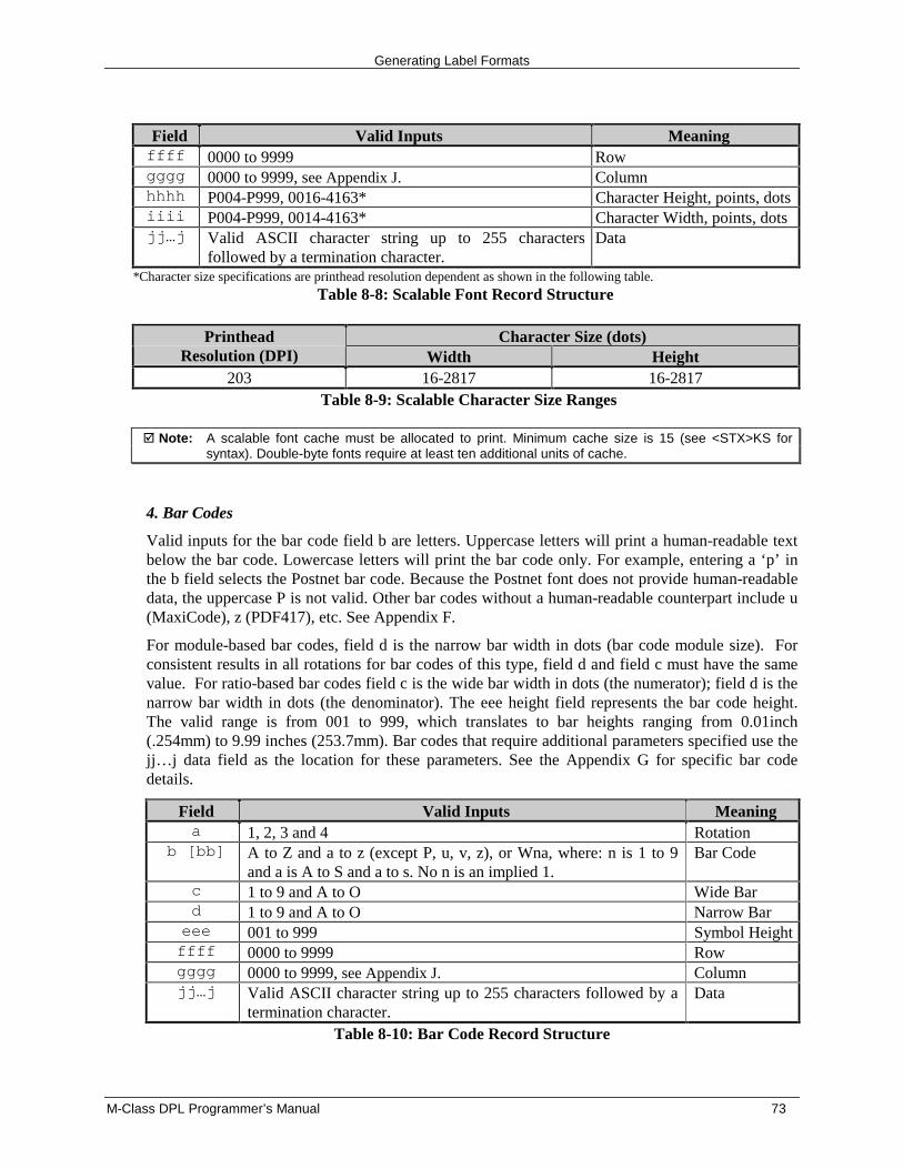
Generating Label Formats
M-Class DPL Programmer’s Manual 73
Field Valid Inputs Meaningffff 0000 to 9999 Rowgggg 0000 to 9999, see Appendix J. Columnhhhh P004-P999, 0016-4163* Character Height, points, dotsiiii P004-P999, 0014-4163* Character Width, points, dotsjj…j Valid ASCII character string up to 255 characters
followed by a termination character.Data
*Character size specifications are printhead resolution dependent as shown in the following table.
Table 8-8: Scalable Font Record Structure
Character Size (dots)PrintheadResolution (DPI) Width Height
203 16-2817 16-2817Table 8-9: Scalable Character Size Ranges
� Note: A scalable font cache must be allocated to print. Minimum cache size is 15 (see <STX>KS forsyntax). Double-byte fonts require at least ten additional units of cache.
4. Bar Codes
Valid inputs for the bar code field b are letters. Uppercase letters will print a human-readable textbelow the bar code. Lowercase letters will print the bar code only. For example, entering a ‘p’ inthe b field selects the Postnet bar code. Because the Postnet font does not provide human-readabledata, the uppercase P is not valid. Other bar codes without a human-readable counterpart include u(MaxiCode), z (PDF417), etc. See Appendix F.
For module-based bar codes, field d is the narrow bar width in dots (bar code module size). Forconsistent results in all rotations for bar codes of this type, field d and field c must have the samevalue. For ratio-based bar codes field c is the wide bar width in dots (the numerator); field d is thenarrow bar width in dots (the denominator). The eee height field represents the bar code height.The valid range is from 001 to 999, which translates to bar heights ranging from 0.01inch(.254mm) to 9.99 inches (253.7mm). Bar codes that require additional parameters specified use thejj…j data field as the location for these parameters. See the Appendix G for specific bar codedetails.
Field Valid Inputs Meaninga 1, 2, 3 and 4 Rotation
b [bb] A to Z and a to z (except P, u, v, z), or Wna, where: n is 1 to 9and a is A to S and a to s. No n is an implied 1.
Bar Code
c 1 to 9 and A to O Wide Bard 1 to 9 and A to O Narrow Bareee 001 to 999 Symbol Heightffff 0000 to 9999 Rowgggg 0000 to 9999, see Appendix J. Columnjj…j Valid ASCII character string up to 255 characters followed by a
termination character.Data
Table 8-10: Bar Code Record Structure
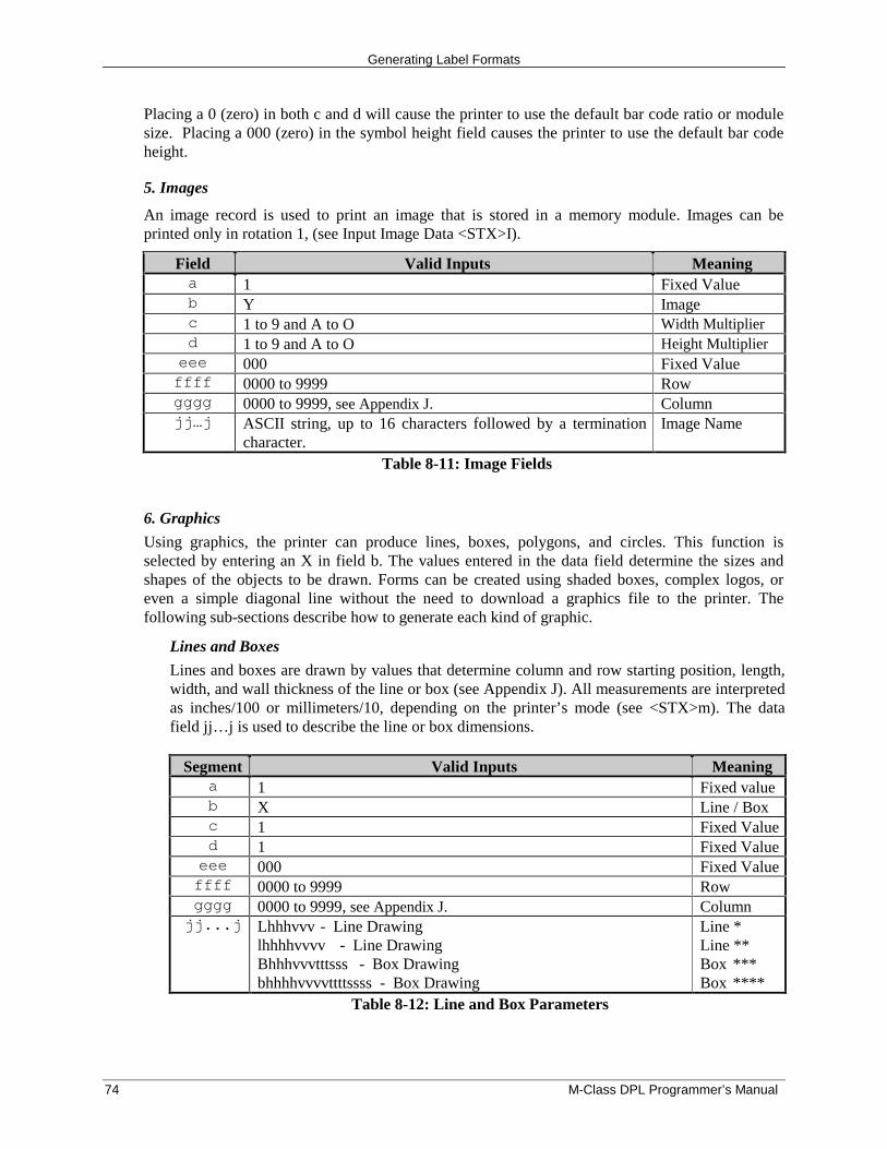
Generating Label Formats
74 M-Class DPL Programmer’s Manual
Placing a 0 (zero) in both c and d will cause the printer to use the default bar code ratio or modulesize. Placing a 000 (zero) in the symbol height field causes the printer to use the default bar codeheight.
5. Images
An image record is used to print an image that is stored in a memory module. Images can beprinted only in rotation 1, (see Input Image Data <STX>I).
Field Valid Inputs Meaninga 1 Fixed Valueb Y Imagec 1 to 9 and A to O Width Multiplierd 1 to 9 and A to O Height Multipliereee 000 Fixed Valueffff 0000 to 9999 Rowgggg 0000 to 9999, see Appendix J. Columnjj…j ASCII string, up to 16 characters followed by a termination
character.Image Name
Table 8-11: Image Fields
6. Graphics
Using graphics, the printer can produce lines, boxes, polygons, and circles. This function isselected by entering an X in field b. The values entered in the data field determine the sizes andshapes of the objects to be drawn. Forms can be created using shaded boxes, complex logos, oreven a simple diagonal line without the need to download a graphics file to the printer. Thefollowing sub-sections describe how to generate each kind of graphic.
Lines and Boxes
Lines and boxes are drawn by values that determine column and row starting position, length,width, and wall thickness of the line or box (see Appendix J). All measurements are interpretedas inches/100 or millimeters/10, depending on the printer’s mode (see <STX>m). The datafield jj…j is used to describe the line or box dimensions.
Segment Valid Inputs Meaninga 1 Fixed valueb X Line / Boxc 1 Fixed Valued 1 Fixed Valueeee 000 Fixed Valueffff 0000 to 9999 Rowgggg 0000 to 9999, see Appendix J. Columnjj...j Lhhhvvv - Line Drawing
lhhhhvvvv - Line DrawingBhhhvvvtttsss - Box Drawingbhhhhvvvvttttssss - Box Drawing
Line *Line **Box ***Box ****
Table 8-12: Line and Box Parameters
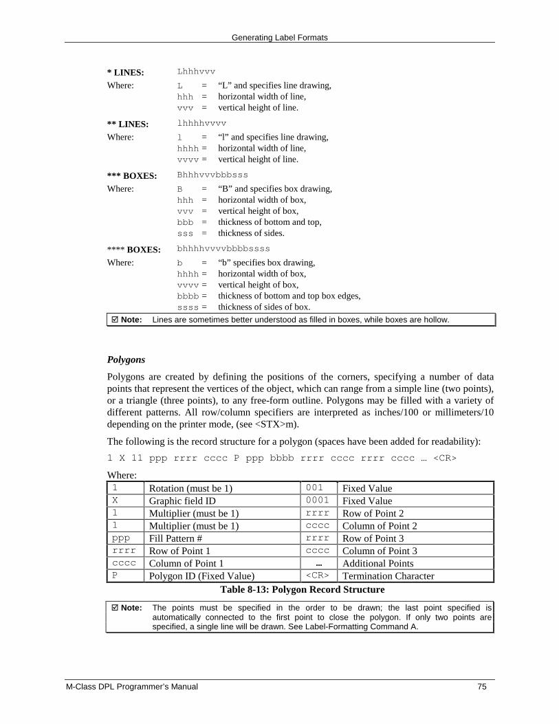
Generating Label Formats
M-Class DPL Programmer’s Manual 75
* LINES: Lhhhvvv
Where: L = “L” and specifies line drawing,hhh = horizontal width of line,vvv = vertical height of line.
** LINES: lhhhhvvvv
Where: l = “l” and specifies line drawing,hhhh = horizontal width of line,vvvv = vertical height of line.
*** BOXES: Bhhhvvvbbbsss
Where: B = “B” and specifies box drawing,hhh = horizontal width of box,vvv = vertical height of box,bbb = thickness of bottom and top,sss = thickness of sides.
**** BOXES: bhhhhvvvvbbbbssss
Where: b = “b” specifies box drawing,hhhh = horizontal width of box,vvvv = vertical height of box,bbbb = thickness of bottom and top box edges,ssss = thickness of sides of box.
� Note: Lines are sometimes better understood as filled in boxes, while boxes are hollow.
Polygons
Polygons are created by defining the positions of the corners, specifying a number of datapoints that represent the vertices of the object, which can range from a simple line (two points),or a triangle (three points), to any free-form outline. Polygons may be filled with a variety ofdifferent patterns. All row/column specifiers are interpreted as inches/100 or millimeters/10depending on the printer mode, (see <STX>m).
The following is the record structure for a polygon (spaces have been added for readability):
1 X 11 ppp rrrr cccc P ppp bbbb rrrr cccc rrrr cccc … <CR>
Where:1 Rotation (must be 1) 001 Fixed ValueX Graphic field ID 0001 Fixed Value1 Multiplier (must be 1) rrrr Row of Point 21 Multiplier (must be 1) cccc Column of Point 2ppp Fill Pattern # rrrr Row of Point 3rrrr Row of Point 1 cccc Column of Point 3cccc Column of Point 1 … Additional PointsP Polygon ID (Fixed Value) <CR> Termination Character
Table 8-13: Polygon Record Structure
� Note: The points must be specified in the order to be drawn; the last point specified isautomatically connected to the first point to close the polygon. If only two points arespecified, a single line will be drawn. See Label-Formatting Command A.
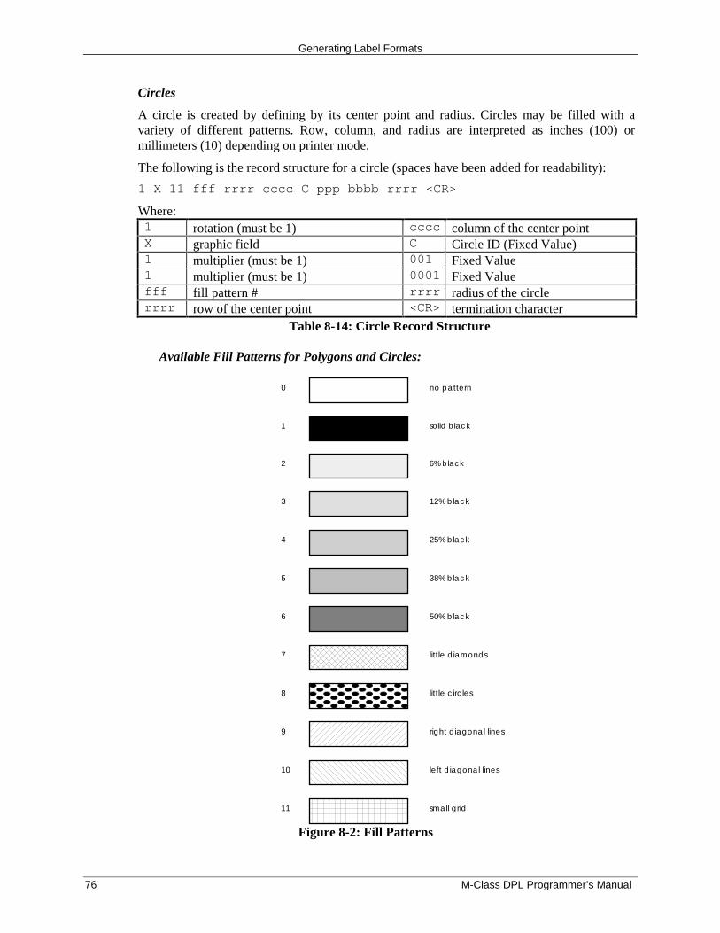
Generating Label Formats
76 M-Class DPL Programmer’s Manual
Circles
A circle is created by defining by its center point and radius. Circles may be filled with avariety of different patterns. Row, column, and radius are interpreted as inches (100) ormillimeters (10) depending on printer mode.
The following is the record structure for a circle (spaces have been added for readability):
1 X 11 fff rrrr cccc C ppp bbbb rrrr <CR>
Where:1 rotation (must be 1) cccc column of the center pointX graphic field C Circle ID (Fixed Value)1 multiplier (must be 1) 001 Fixed Value1 multiplier (must be 1) 0001 Fixed Valuefff fill pattern # rrrr radius of the circlerrrr row of the center point <CR> termination character
Table 8-14: Circle Record Structure
Available Fill Patterns for Polygons and Circles:
0 no pattern
1 solid black
2 6% black
3 12% black
4 25% black
5 38% black
6 50% black
7 little diamonds
8 little circles
9 right diagonal lines
10 left diagonal lines
11 small grid
Figure 8-2: Fill Patterns
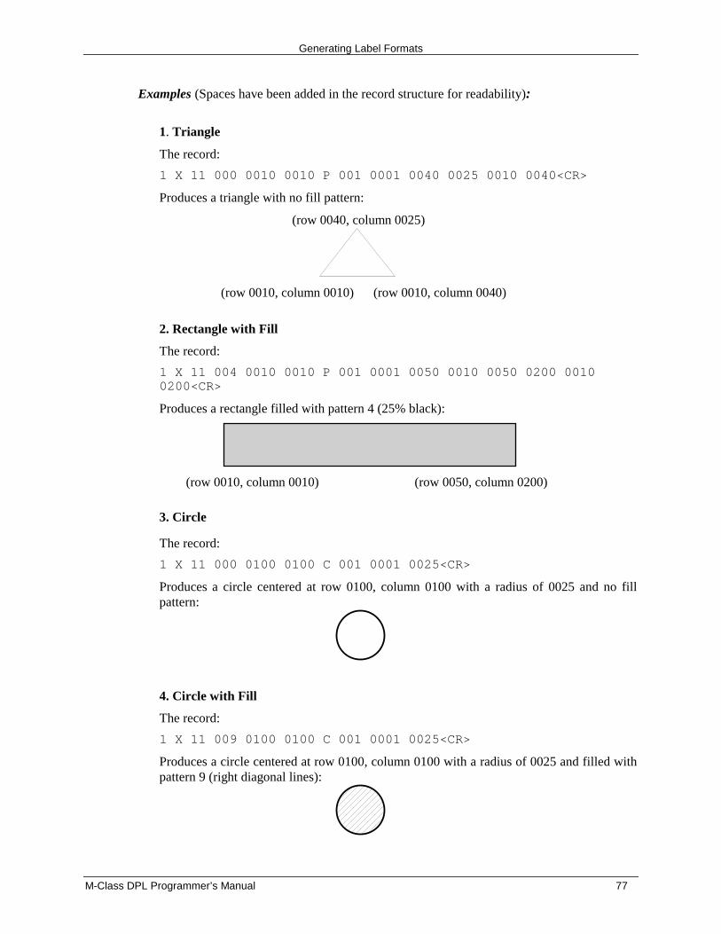
Generating Label Formats
M-Class DPL Programmer’s Manual 77
Examples (Spaces have been added in the record structure for readability):
1. Triangle
The record:
1 X 11 000 0010 0010 P 001 0001 0040 0025 0010 0040<CR>
Produces a triangle with no fill pattern:
(row 0040, column 0025)
(row 0010, column 0010) (row 0010, column 0040)
2. Rectangle with Fill
The record:
1 X 11 004 0010 0010 P 001 0001 0050 0010 0050 0200 00100200<CR>
Produces a rectangle filled with pattern 4 (25% black):
(row 0010, column 0010) (row 0050, column 0200)
3. Circle
The record:
1 X 11 000 0100 0100 C 001 0001 0025<CR>
Produces a circle centered at row 0100, column 0100 with a radius of 0025 and no fillpattern:
4. Circle with Fill
The record:
1 X 11 009 0100 0100 C 001 0001 0025<CR>
Produces a circle centered at row 0100, column 0100 with a radius of 0025 and filled withpattern 9 (right diagonal lines):

Generating Label Formats
78 M-Class DPL Programmer’s Manual
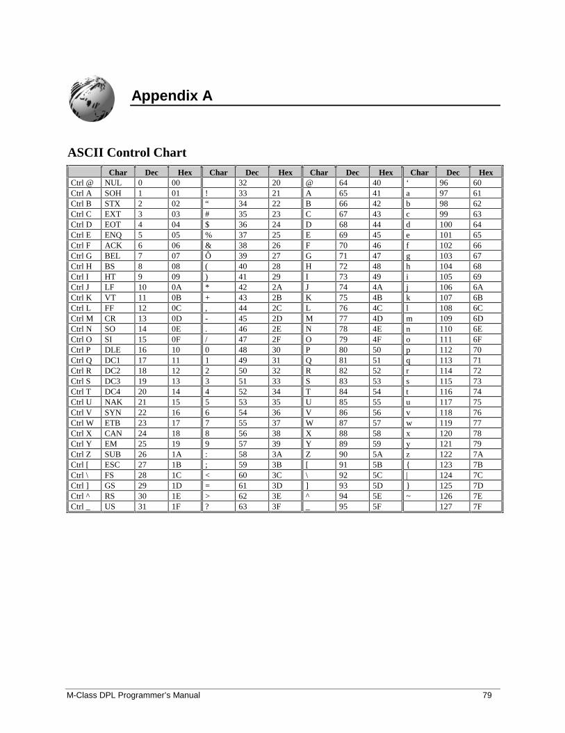
M-Class DPL Programmer’s Manual 79
Appendix A
ASCII Control ChartChar Dec Hex Char Dec Hex Char Dec Hex Char Dec Hex
Ctrl @ NUL 0 00 32 20 @ 64 40 ‘ 96 60Ctrl A SOH 1 01 ! 33 21 A 65 41 a 97 61Ctrl B STX 2 02 “ 34 22 B 66 42 b 98 62Ctrl C EXT 3 03 # 35 23 C 67 43 c 99 63Ctrl D EOT 4 04 $ 36 24 D 68 44 d 100 64Ctrl E ENQ 5 05 % 37 25 E 69 45 e 101 65Ctrl F ACK 6 06 & 38 26 F 70 46 f 102 66Ctrl G BEL 7 07 Ô 39 27 G 71 47 g 103 67Ctrl H BS 8 08 ( 40 28 H 72 48 h 104 68Ctrl I HT 9 09 ) 41 29 I 73 49 i 105 69Ctrl J LF 10 0A * 42 2A J 74 4A j 106 6ACtrl K VT 11 0B + 43 2B K 75 4B k 107 6BCtrl L FF 12 0C , 44 2C L 76 4C l 108 6CCtrl M CR 13 0D - 45 2D M 77 4D m 109 6DCtrl N SO 14 0E . 46 2E N 78 4E n 110 6ECtrl O SI 15 0F / 47 2F O 79 4F o 111 6FCtrl P DLE 16 10 0 48 30 P 80 50 p 112 70Ctrl Q DC1 17 11 1 49 31 Q 81 51 q 113 71Ctrl R DC2 18 12 2 50 32 R 82 52 r 114 72Ctrl S DC3 19 13 3 51 33 S 83 53 s 115 73Ctrl T DC4 20 14 4 52 34 T 84 54 t 116 74Ctrl U NAK 21 15 5 53 35 U 85 55 u 117 75Ctrl V SYN 22 16 6 54 36 V 86 56 v 118 76Ctrl W ETB 23 17 7 55 37 W 87 57 w 119 77Ctrl X CAN 24 18 8 56 38 X 88 58 x 120 78Ctrl Y EM 25 19 9 57 39 Y 89 59 y 121 79Ctrl Z SUB 26 1A : 58 3A Z 90 5A z 122 7ACtrl [ ESC 27 1B ; 59 3B [ 91 5B { 123 7BCtrl \ FS 28 1C < 60 3C \ 92 5C | 124 7CCtrl ] GS 29 1D = 61 3D ] 93 5D } 125 7DCtrl ^ RS 30 1E > 62 3E ^ 94 5E ~ 126 7ECtrl _ US 31 1F ? 63 3F _ 95 5F 127 7F
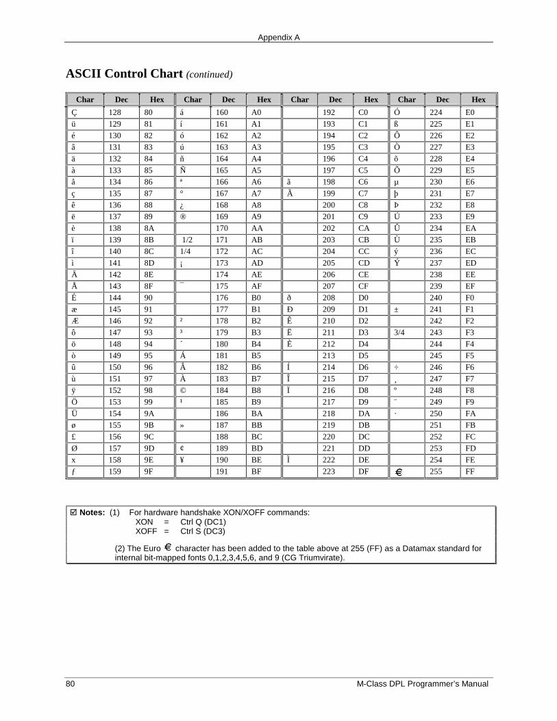
Appendix A
80 M-Class DPL Programmer’s Manual
ASCII Control Chart (continued)
Char Dec Hex Char Dec Hex Char Dec Hex Char Dec Hex
Ç 128 80 á 160 A0 192 C0 Ó 224 E0
ü 129 81 í 161 A1 193 C1 ß 225 E1
é 130 82 ó 162 A2 194 C2 Ô 226 E2
â 131 83 ú 163 A3 195 C3 Ò 227 E3
ä 132 84 ñ 164 A4 196 C4 õ 228 E4
à 133 85 Ñ 165 A5 197 C5 Õ 229 E5
å 134 86 ª 166 A6 ã 198 C6 µ 230 E6
ç 135 87 ° 167 A7 Ã 199 C7 þ 231 E7
ê 136 88 ¿ 168 A8 200 C8 Þ 232 E8
ë 137 89 ® 169 A9 201 C9 Ú 233 E9
è 138 8A 170 AA 202 CA Û 234 EA
ï 139 8B 1/2 171 AB 203 CB Ù 235 EB
î 140 8C 1/4 172 AC 204 CC ý 236 EC
ì 141 8D ¡ 173 AD 205 CD Ý 237 ED
Ä 142 8E 174 AE 206 CE 238 EE
Å 143 8F ¯ 175 AF 207 CF 239 EF
É 144 90 176 B0 ð 208 D0 240 F0
æ 145 91 177 B1 Ð 209 D1 ± 241 F1
Æ 146 92 ² 178 B2 Ê 210 D2 242 F2
ô 147 93 ³ 179 B3 Ë 211 D3 3/4 243 F3
ö 148 94 ´ 180 B4 È 212 D4 244 F4
ò 149 95 Á 181 B5 213 D5 245 F5
û 150 96 Â 182 B6 Í 214 D6 ÷ 246 F6
ù 151 97 À 183 B7 Î 215 D7 ¸ 247 F7
ÿ 152 98 © 184 B8 Ï 216 D8 º 248 F8
Ö 153 99 ¹ 185 B9 217 D9 ¨ 249 F9
Ü 154 9A 186 BA 218 DA · 250 FA
ø 155 9B » 187 BB 219 DB 251 FB
£ 156 9C 188 BC 220 DC 252 FC
Ø 157 9D ¢ 189 BD 221 DD 253 FD
x 158 9E ¥ 190 BE Ì 222 DE 254 FE
ƒ 159 9F 191 BF 223 DF 255 FF
� Notes: (1) For hardware handshake XON/XOFF commands:XON = Ctrl Q (DC1)XOFF = Ctrl S (DC3)
(2) The Euro character has been added to the table above at 255 (FF) as a Datamax standard forinternal bit-mapped fonts 0,1,2,3,4,5,6, and 9 (CG Triumvirate).
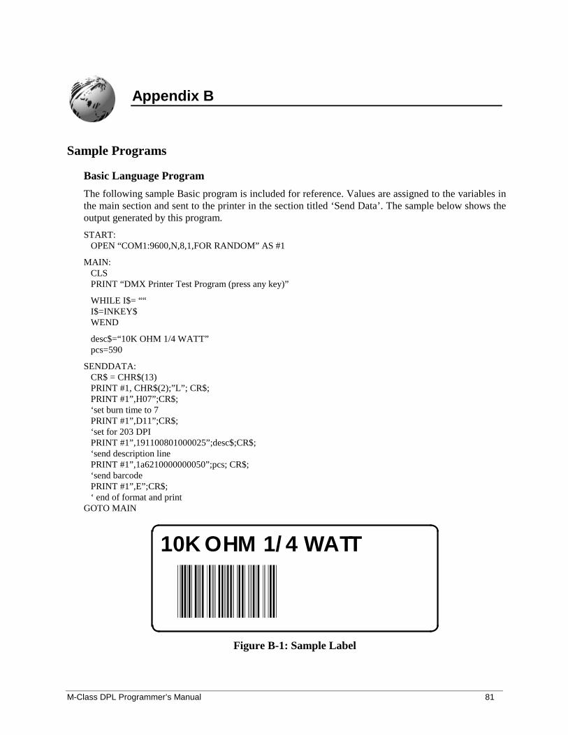
M-Class DPL Programmer’s Manual 81
Appendix B
Sample Programs
Basic Language Program
The following sample Basic program is included for reference. Values are assigned to the variables inthe main section and sent to the printer in the section titled ‘Send Data’. The sample below shows theoutput generated by this program.
START: OPEN “COM1:9600,N,8,1,FOR RANDOM” AS #1
MAIN: CLS PRINT “DMX Printer Test Program (press any key)”
WHILE I$= ““ I$=INKEY$ WEND
desc$=“10K OHM 1/4 WATT” pcs=590
SENDDATA: CR$ = CHR$(13) PRINT #1, CHR$(2);”L”; CR$; PRINT #1”,H07”;CR$; ‘set burn time to 7 PRINT #1”,D11”;CR$; ‘set for 203 DPI PRINT #1”,191100801000025”;desc$;CR$; ‘send description line PRINT #1”,1a6210000000050”;pcs; CR$; ‘send barcode PRINT #1”,E”;CR$; ‘ end of format and printGOTO MAIN
10K OHM 1/4 WATT
Figure B-1: Sample Label
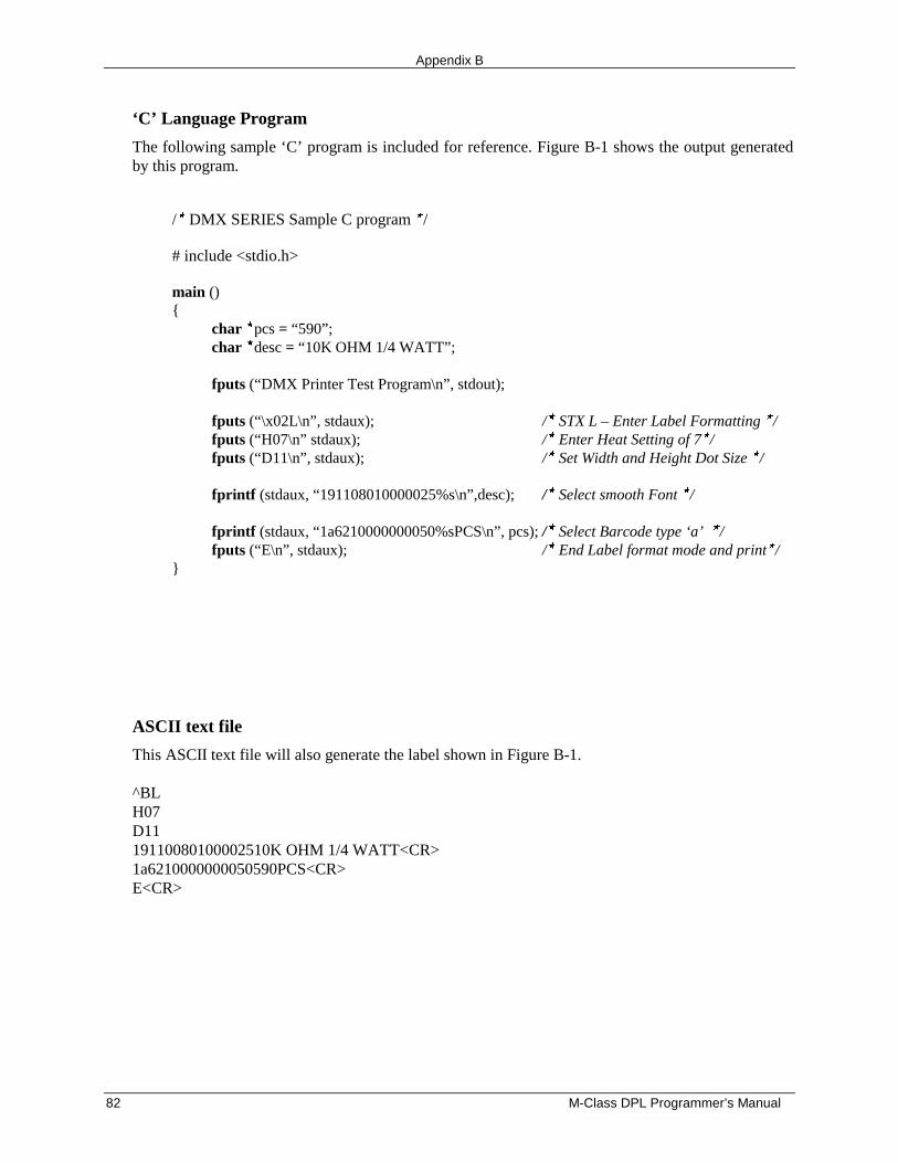
Appendix B
82 M-Class DPL Programmer’s Manual
‘C’ Language Program
The following sample ‘C’ program is included for reference. Figure B-1 shows the output generatedby this program.
/� DMX SERIES Sample C program �/
# include <stdio.h>
main (){
char �pcs = “590”;char �desc = “10K OHM 1/4 WATT”;
fputs (“DMX Printer Test Program\n”, stdout);
fputs (“\x02L\n”, stdaux); /� STX L – Enter Label Formatting �/fputs (“H07\n” stdaux); /� Enter Heat Setting of 7�/fputs (“D11\n”, stdaux); /� Set Width and Height Dot Size �/
fprintf (stdaux, “191108010000025%s\n”,desc); /� Select smooth Font �/
fprintf (stdaux, “1a6210000000050%sPCS\n”, pcs); /� Select Barcode type ‘a’ �/fputs (“E\n”, stdaux); /� End Label format mode and print�/
}
ASCII text file
This ASCII text file will also generate the label shown in Figure B-1.
^BLH07D1119110080100002510K OHM 1/4 WATT<CR>1a6210000000050590PCS<CR>E<CR>
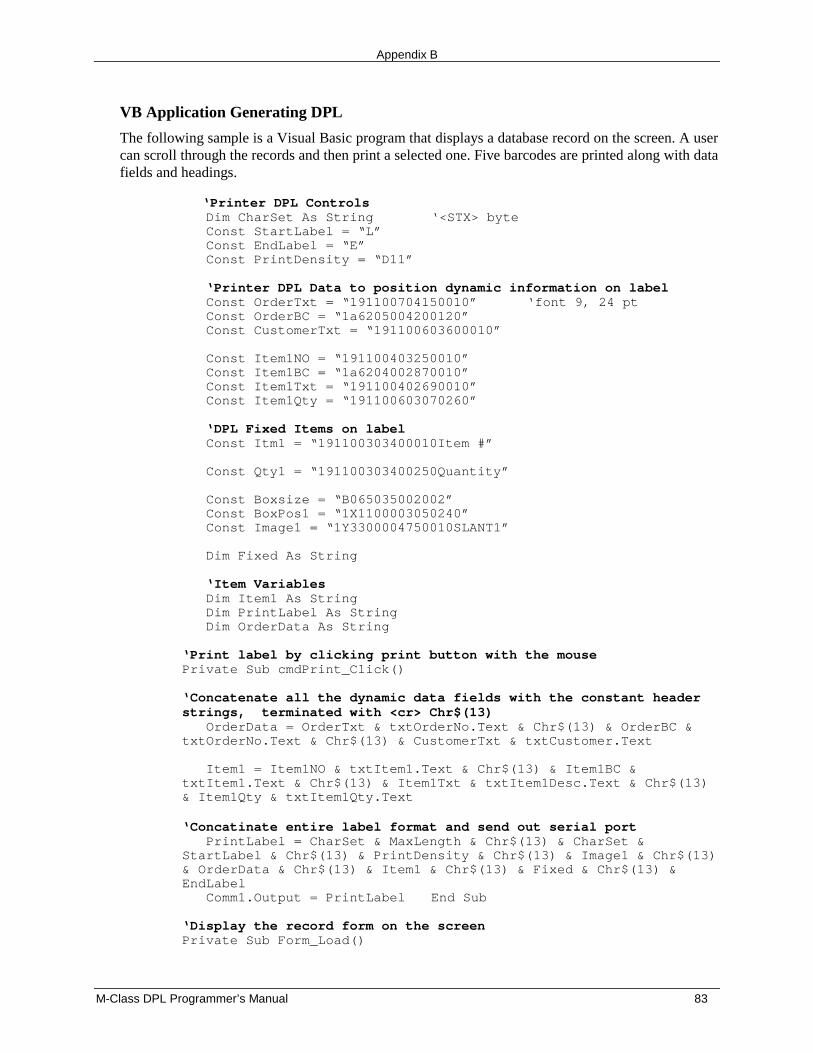
Appendix B
M-Class DPL Programmer’s Manual 83
VB Application Generating DPL
The following sample is a Visual Basic program that displays a database record on the screen. A usercan scroll through the records and then print a selected one. Five barcodes are printed along with datafields and headings.
‘Printer DPL Controls Dim CharSet As String ‘<STX> byte Const StartLabel = “L” Const EndLabel = “E” Const PrintDensity = “D11”
‘Printer DPL Data to position dynamic information on label Const OrderTxt = “191100704150010” ‘font 9, 24 pt Const OrderBC = “1a6205004200120” Const CustomerTxt = “191100603600010”
Const Item1NO = “191100403250010” Const Item1BC = “1a6204002870010” Const Item1Txt = “191100402690010” Const Item1Qty = “191100603070260”
‘DPL Fixed Items on label Const Itm1 = “191100303400010Item #”
Const Qty1 = “191100303400250Quantity”
Const Boxsize = “B065035002002” Const BoxPos1 = “1X1100003050240” Const Image1 = “1Y3300004750010SLANT1”
Dim Fixed As String
‘Item Variables Dim Item1 As String Dim PrintLabel As String Dim OrderData As String
‘Print label by clicking print button with the mousePrivate Sub cmdPrint_Click()
‘Concatenate all the dynamic data fields with the constant headerstrings, terminated with <cr> Chr$(13) OrderData = OrderTxt & txtOrderNo.Text & Chr$(13) & OrderBC &txtOrderNo.Text & Chr$(13) & CustomerTxt & txtCustomer.Text
Item1 = Item1NO & txtItem1.Text & Chr$(13) & Item1BC &txtItem1.Text & Chr$(13) & Item1Txt & txtItem1Desc.Text & Chr$(13)& Item1Qty & txtItem1Qty.Text
‘Concatinate entire label format and send out serial port PrintLabel = CharSet & MaxLength & Chr$(13) & CharSet &StartLabel & Chr$(13) & PrintDensity & Chr$(13) & Image1 & Chr$(13)& OrderData & Chr$(13) & Item1 & Chr$(13) & Fixed & Chr$(13) &EndLabel Comm1.Output = PrintLabel End Sub
‘Display the record form on the screenPrivate Sub Form_Load()
Appendix B
84 M-Class DPL Programmer’s Manual
Fixed = Itm1 & Chr$(13) & Chr$(13) & Qty1 & Chr$(13) & Chr$(13)& BoxPos1 & Boxsize & Chr$(13) CharSet = Chr$(126) ‘Alternate <stx> character ~ MComm.PortOpen = 1 ‘Open the serial portEnd Sub
‘Exit the program by clicking Exit button with the mouse Private Sub cmdExit_Click() Comm1.PortOpen = 0 ‘Close down the serial port EndEnd Sub
‘Exit the program by clicking Exit button with the mouse Private Sub cmdExit_Click() Comm1.PortOpen = 0 ‘Close down the serial port EndEnd Sub
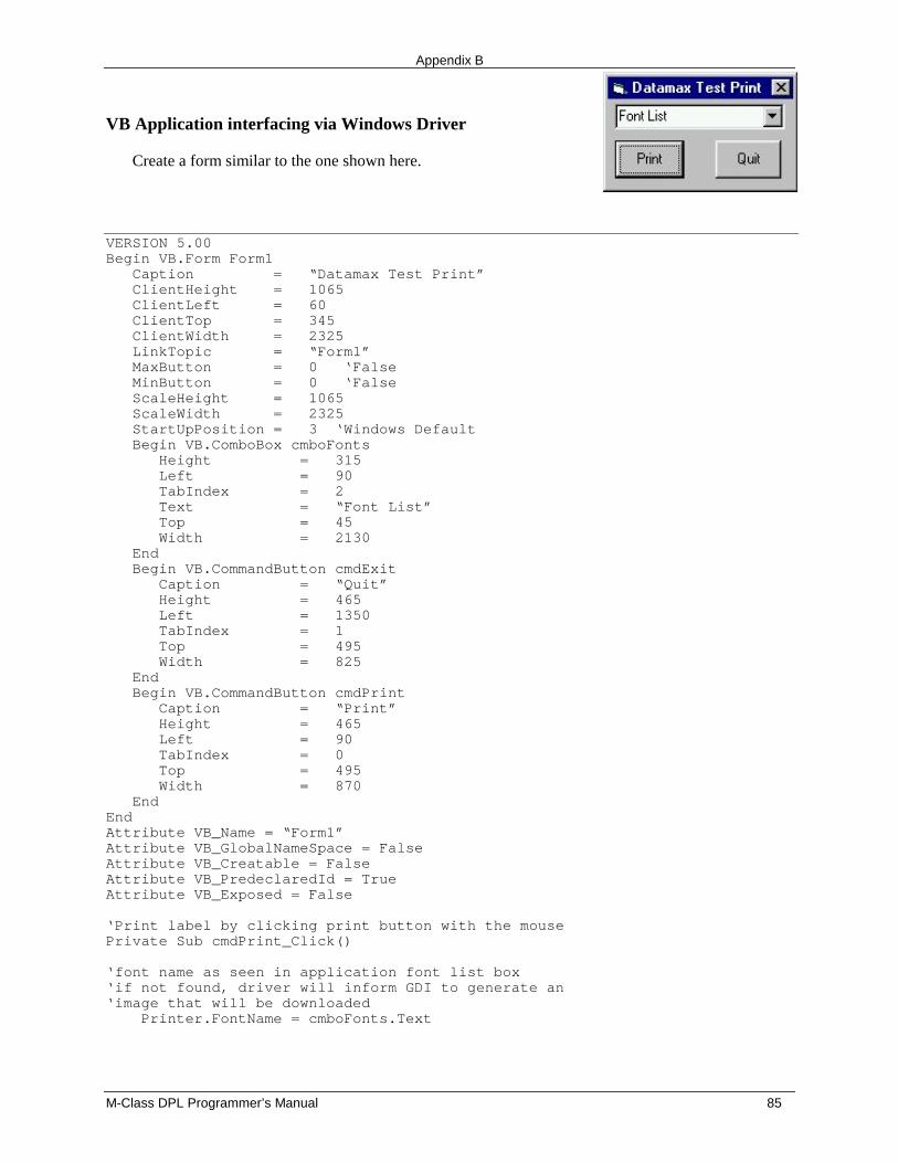
Appendix B
M-Class DPL Programmer’s Manual 85
VB Application interfacing via Windows Driver
Create a form similar to the one shown here.
VERSION 5.00Begin VB.Form Form1 Caption = “Datamax Test Print” ClientHeight = 1065 ClientLeft = 60 ClientTop = 345 ClientWidth = 2325 LinkTopic = “Form1” MaxButton = 0 ‘False MinButton = 0 ‘False ScaleHeight = 1065 ScaleWidth = 2325 StartUpPosition = 3 ‘Windows Default Begin VB.ComboBox cmboFonts Height = 315 Left = 90 TabIndex = 2 Text = “Font List” Top = 45 Width = 2130 End Begin VB.CommandButton cmdExit Caption = “Quit” Height = 465 Left = 1350 TabIndex = 1 Top = 495 Width = 825 End Begin VB.CommandButton cmdPrint Caption = “Print” Height = 465 Left = 90 TabIndex = 0 Top = 495 Width = 870 EndEndAttribute VB_Name = “Form1”Attribute VB_GlobalNameSpace = FalseAttribute VB_Creatable = FalseAttribute VB_PredeclaredId = TrueAttribute VB_Exposed = False
‘Print label by clicking print button with the mousePrivate Sub cmdPrint_Click()
‘font name as seen in application font list box‘if not found, driver will inform GDI to generate an‘image that will be downloaded Printer.FontName = cmboFonts.Text
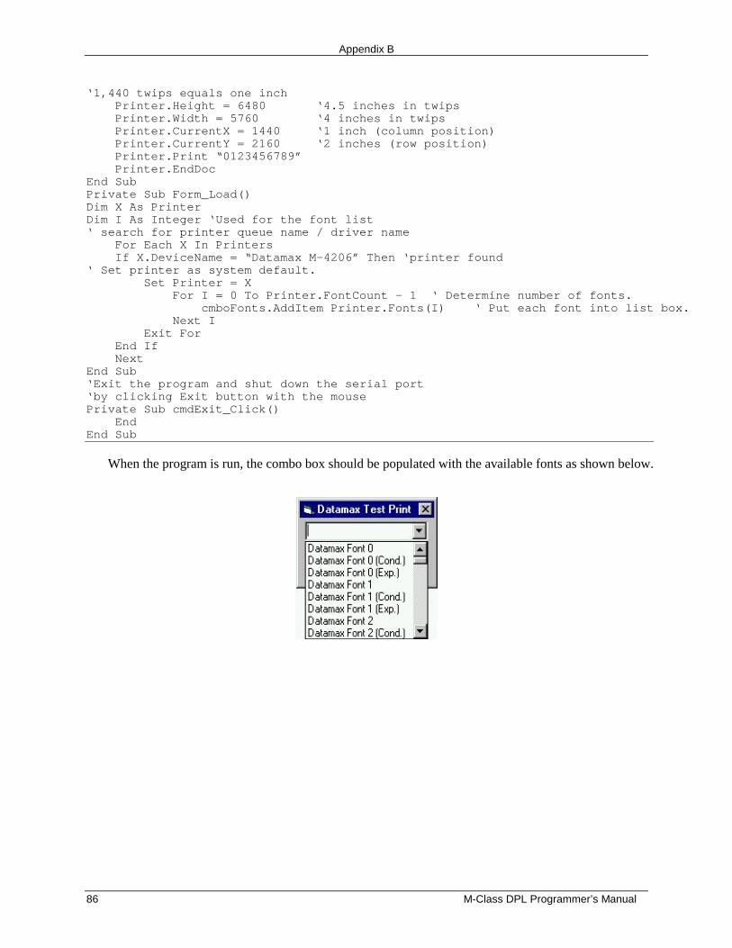
Appendix B
86 M-Class DPL Programmer’s Manual
‘1,440 twips equals one inch Printer.Height = 6480 ‘4.5 inches in twips Printer.Width = 5760 ‘4 inches in twips Printer.CurrentX = 1440 ‘1 inch (column position) Printer.CurrentY = 2160 ‘2 inches (row position) Printer.Print “0123456789” Printer.EndDocEnd SubPrivate Sub Form_Load()Dim X As PrinterDim I As Integer ‘Used for the font list‘ search for printer queue name / driver name For Each X In Printers If X.DeviceName = “Datamax M-4206” Then ‘printer found‘ Set printer as system default. Set Printer = X For I = 0 To Printer.FontCount - 1 ‘ Determine number of fonts. cmboFonts.AddItem Printer.Fonts(I) ‘ Put each font into list box. Next I Exit For End If NextEnd Sub‘Exit the program and shut down the serial port‘by clicking Exit button with the mousePrivate Sub cmdExit_Click() EndEnd Sub
When the program is run, the combo box should be populated with the available fonts as shown below.
Appendix B
M-Class DPL Programmer’s Manual 87
VB Application interfacing via Windows Driver
This is a sample Visual Basic program that checks for any printer driver attached to “LPT1:”. If oneis installed then a DPL file can be printed via the print driver. Note that this does not have to be aDatamax DPL print driver. DPL is created by the application and sent to LPT1.
To begin, a global variable called SelPrinter must be defined as a string. Then use the followingcode to create a .frm file.
VERSION 5.00Object = “{F9043C88-F6F2-101A-A3C9-08002B2F49FB}#1.2#0”; “comdlg32.ocx”Begin VB.Form Form1 Caption = “Form1” ClientHeight = 1290 ClientLeft = 165 ClientTop = 735 ClientWidth = 3750 LinkTopic = “Form1” MaxButton = 0 ‘False MinButton = 0 ‘False ScaleHeight = 1290 ScaleWidth = 3750 StartUpPosition = 3 ‘Windows Default Begin MSComDlg.CommonDialog CommonDialog1 Left = 1635 Top = 765 _ExtentX = 847 _ExtentY = 847 _Version = 393216 End Begin VB.CommandButton cmdClose Cancel = -1 ‘True Caption = “Close” Height = 372 Left = 2400 TabIndex = 3 Top = 735 Width = 972 End Begin VB.CommandButton cmdStoreImage Caption = “Print” Default = -1 ‘True Height = 372 Left = 240 TabIndex = 2 Top = 735 Width = 972 End Begin VB.TextBox txtFile Height = 288 Left = 120 TabIndex = 1 Top = 360 Width = 3492 End Begin VB.Label Label1 Caption = “File Name” Height = 255
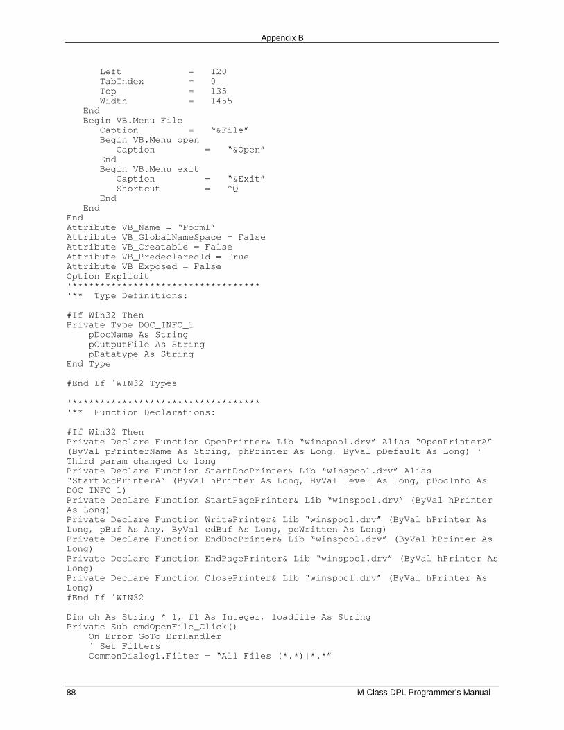
Appendix B
88 M-Class DPL Programmer’s Manual
Left = 120 TabIndex = 0 Top = 135 Width = 1455 End Begin VB.Menu File Caption = “&File” Begin VB.Menu open Caption = “&Open” End Begin VB.Menu exit Caption = “&Exit” Shortcut = ^Q End EndEndAttribute VB_Name = “Form1”Attribute VB_GlobalNameSpace = FalseAttribute VB_Creatable = FalseAttribute VB_PredeclaredId = TrueAttribute VB_Exposed = FalseOption Explicit‘**********************************‘** Type Definitions:
#If Win32 ThenPrivate Type DOC_INFO_1 pDocName As String pOutputFile As String pDatatype As StringEnd Type
#End If ‘WIN32 Types
‘**********************************‘** Function Declarations:
#If Win32 ThenPrivate Declare Function OpenPrinter& Lib “winspool.drv” Alias “OpenPrinterA”(ByVal pPrinterName As String, phPrinter As Long, ByVal pDefault As Long) ‘Third param changed to longPrivate Declare Function StartDocPrinter& Lib “winspool.drv” Alias“StartDocPrinterA” (ByVal hPrinter As Long, ByVal Level As Long, pDocInfo AsDOC_INFO_1)Private Declare Function StartPagePrinter& Lib “winspool.drv” (ByVal hPrinterAs Long)Private Declare Function WritePrinter& Lib “winspool.drv” (ByVal hPrinter AsLong, pBuf As Any, ByVal cdBuf As Long, pcWritten As Long)Private Declare Function EndDocPrinter& Lib “winspool.drv” (ByVal hPrinter AsLong)Private Declare Function EndPagePrinter& Lib “winspool.drv” (ByVal hPrinter AsLong)Private Declare Function ClosePrinter& Lib “winspool.drv” (ByVal hPrinter AsLong)#End If ‘WIN32
Dim ch As String * 1, f1 As Integer, loadfile As StringPrivate Sub cmdOpenFile_Click() On Error GoTo ErrHandler ‘ Set Filters CommonDialog1.Filter = “All Files (*.*)|*.*”
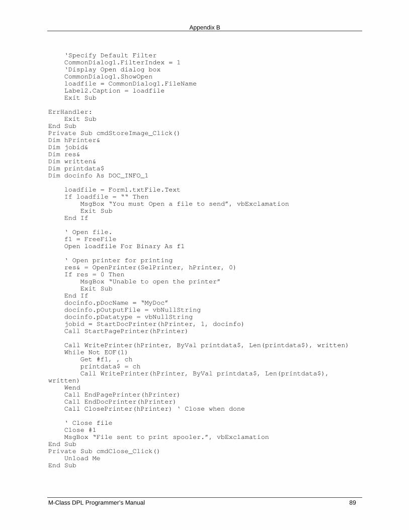
Appendix B
M-Class DPL Programmer’s Manual 89
‘Specify Default Filter CommonDialog1.FilterIndex = 1 ‘Display Open dialog box CommonDialog1.ShowOpen loadfile = CommonDialog1.FileName Label2.Caption = loadfile Exit Sub
ErrHandler: Exit SubEnd SubPrivate Sub cmdStoreImage_Click()Dim hPrinter&Dim jobid&Dim res&Dim written&Dim printdata$Dim docinfo As DOC_INFO_1
loadfile = Form1.txtFile.Text If loadfile = ““ Then MsgBox “You must Open a file to send”, vbExclamation Exit Sub End If
‘ Open file. f1 = FreeFile Open loadfile For Binary As f1
‘ Open printer for printing res& = OpenPrinter(SelPrinter, hPrinter, 0) If res = 0 Then MsgBox “Unable to open the printer” Exit Sub End If docinfo.pDocName = “MyDoc” docinfo.pOutputFile = vbNullString docinfo.pDatatype = vbNullString jobid = StartDocPrinter(hPrinter, 1, docinfo) Call StartPagePrinter(hPrinter)
Call WritePrinter(hPrinter, ByVal printdata$, Len(printdata$), written) While Not EOF(1) Get #f1, , ch printdata$ = ch Call WritePrinter(hPrinter, ByVal printdata$, Len(printdata$),written) Wend Call EndPagePrinter(hPrinter) Call EndDocPrinter(hPrinter) Call ClosePrinter(hPrinter) ‘ Close when done
‘ Close file Close #1 MsgBox “File sent to print spooler.”, vbExclamationEnd SubPrivate Sub cmdClose_Click() Unload MeEnd Sub
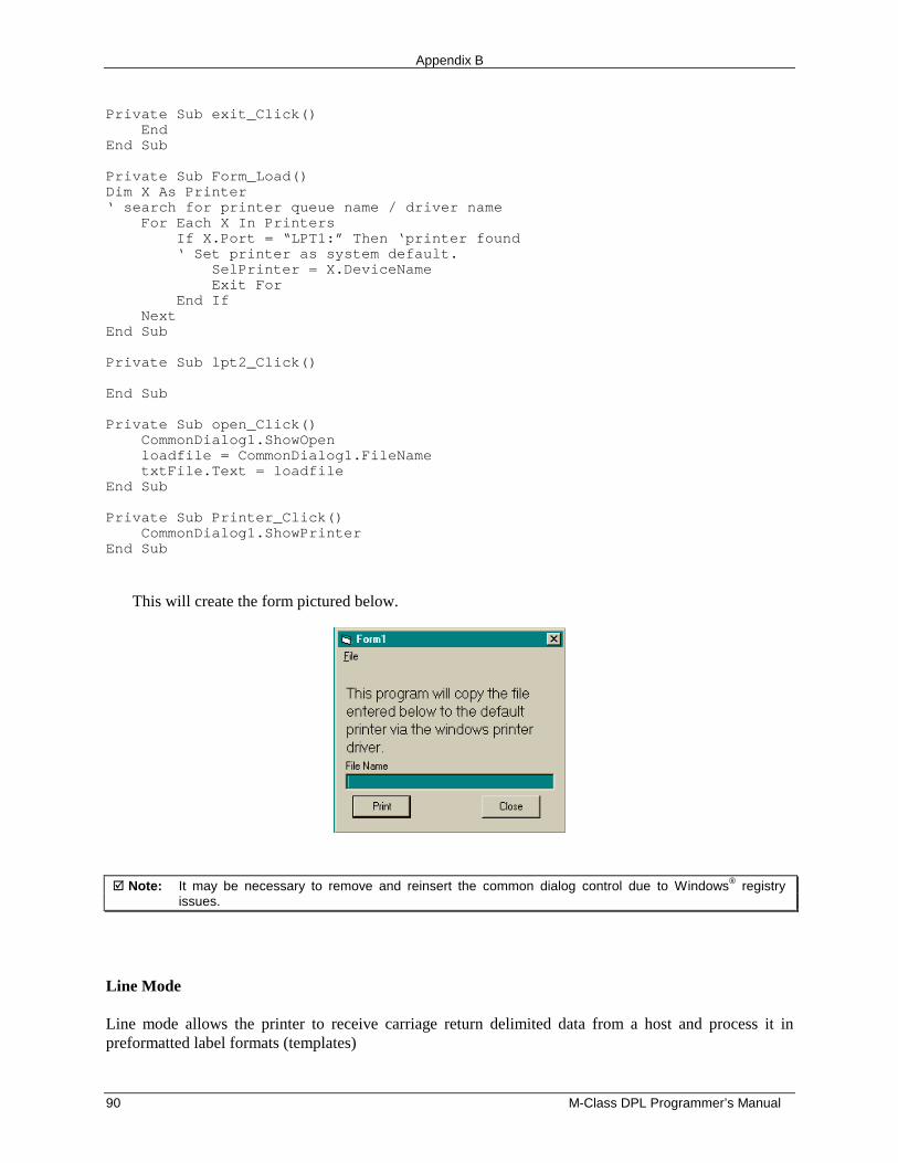
Appendix B
90 M-Class DPL Programmer’s Manual
Private Sub exit_Click() EndEnd Sub
Private Sub Form_Load()Dim X As Printer‘ search for printer queue name / driver name For Each X In Printers If X.Port = “LPT1:” Then ‘printer found ‘ Set printer as system default. SelPrinter = X.DeviceName Exit For End If NextEnd Sub
Private Sub lpt2_Click()
End Sub
Private Sub open_Click() CommonDialog1.ShowOpen loadfile = CommonDialog1.FileName txtFile.Text = loadfileEnd Sub
Private Sub Printer_Click() CommonDialog1.ShowPrinterEnd Sub
This will create the form pictured below.
� Note: It may be necessary to remove and reinsert the common dialog control due to Windows® registryissues.
Line Mode
Line mode allows the printer to receive carriage return delimited data from a host and process it inpreformatted label formats (templates)
Appendix B
M-Class DPL Programmer’s Manual 91
Templates must be named “DMXFRM” or “DMXFRMxx” and stored to memory. When in Line modethe printer will accept raw data and print from the template DMXFRM or if DMXFRMxx wasdownloaded also, then xx> preceding the raw data will select that template. The rules for Update Fields,such as the length of raw data cannot exceed the length of the original string field, still apply.
Example 1
When the file
<STX>LD11151100001600010 REPLACEABLE FIELD #1U151100001200010FIXED FIELD #1151100000800010 REPLACEABLE FIELD #2U151100000400010FIXED FIELD #2151100000000010 REPLACEABLE FIELD #3UQ0001sCDMXFRM
is sent to the printer and then raw data
TEST FIELD #1<CR>TEST FIELD #2<CR>TEST FIELD #3<CR>
is sent while in Line mode, the printer will print:
TEST FIELD #1FIXED FIELD #1TEST FIELD #2FIXED FIELD #2TEST FIELD #3
Appendix B
92 M-Class DPL Programmer’s Manual
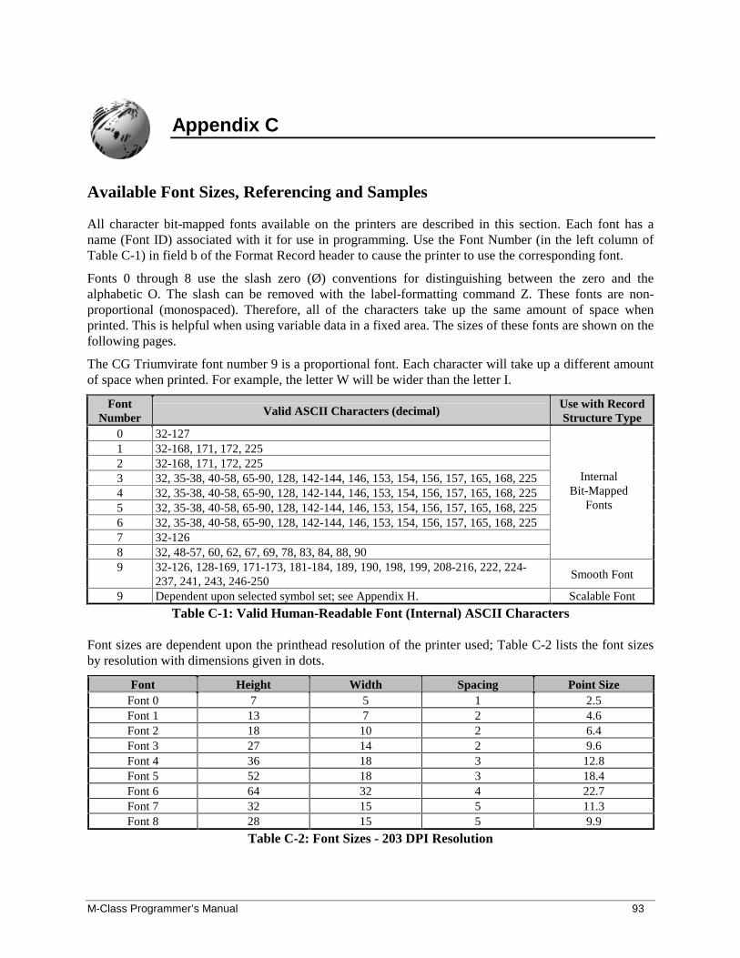
M-Class Programmer’s Manual 93
Appendix C
Available Font Sizes, Referencing and Samples
All character bit-mapped fonts available on the printers are described in this section. Each font has aname (Font ID) associated with it for use in programming. Use the Font Number (in the left column ofTable C-1) in field b of the Format Record header to cause the printer to use the corresponding font.
Fonts 0 through 8 use the slash zero (Ø) conventions for distinguishing between the zero and thealphabetic O. The slash can be removed with the label-formatting command Z. These fonts are non-proportional (monospaced). Therefore, all of the characters take up the same amount of space whenprinted. This is helpful when using variable data in a fixed area. The sizes of these fonts are shown on thefollowing pages.
The CG Triumvirate font number 9 is a proportional font. Each character will take up a different amountof space when printed. For example, the letter W will be wider than the letter I.
FontNumber Valid ASCII Characters (decimal)
Use with RecordStructure Type
0 32-1271 32-168, 171, 172, 2252 32-168, 171, 172, 2253 32, 35-38, 40-58, 65-90, 128, 142-144, 146, 153, 154, 156, 157, 165, 168, 2254 32, 35-38, 40-58, 65-90, 128, 142-144, 146, 153, 154, 156, 157, 165, 168, 2255 32, 35-38, 40-58, 65-90, 128, 142-144, 146, 153, 154, 156, 157, 165, 168, 2256 32, 35-38, 40-58, 65-90, 128, 142-144, 146, 153, 154, 156, 157, 165, 168, 2257 32-1268 32, 48-57, 60, 62, 67, 69, 78, 83, 84, 88, 90
InternalBit-Mapped
Fonts
9 32-126, 128-169, 171-173, 181-184, 189, 190, 198, 199, 208-216, 222, 224-237, 241, 243, 246-250
Smooth Font
9 Dependent upon selected symbol set; see Appendix H. Scalable Font
Table C-1: Valid Human-Readable Font (Internal) ASCII Characters
Font sizes are dependent upon the printhead resolution of the printer used; Table C-2 lists the font sizesby resolution with dimensions given in dots.
Font Height Width Spacing Point SizeFont 0 7 5 1 2.5Font 1 13 7 2 4.6Font 2 18 10 2 6.4Font 3 27 14 2 9.6Font 4 36 18 3 12.8Font 5 52 18 3 18.4Font 6 64 32 4 22.7Font 7 32 15 5 11.3Font 8 28 15 5 9.9
Table C-2: Font Sizes - 203 DPI Resolution
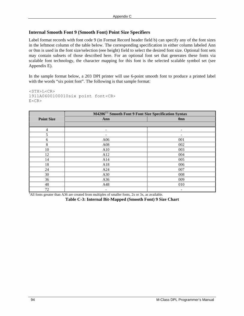
Appendix C
94 M-Class DPL Programmer’s Manual
Internal Smooth Font 9 (Smooth Font) Point Size Specifiers
Label format records with font code 9 (in Format Record header field b) can specify any of the font sizesin the leftmost column of the table below. The corresponding specification in either column labeled Annor 0nn is used in the font size/selection (eee height) field to select the desired font size. Optional font setsmay contain subsets of those described here. For an optional font set that generates these fonts viascalable font technology, the character mapping for this font is the selected scalable symbol set (seeAppendix E).
In the sample format below, a 203 DPI printer will use 6-point smooth font to produce a printed labelwith the words “six point font”. The following is that sample format:
<STX>L<CR>1911A0600100010six point font<CR>E<CR>
M4206[3] Smooth Font 9 Font Size Specification SyntaxAnn 0nnPoint Size
4 - -5 - -6 A06 0018 A08 002
10 A10 00312 A12 00414 A14 00518 A18 00624 A24 00730 A30 00836 A36 00948 A48 01072 - -
3All fonts greater than A36 are created from multiples of smaller fonts, 2x or 3x, as available.
Table C-3: Internal Bit-Mapped (Smooth Font) 9 Size Chart
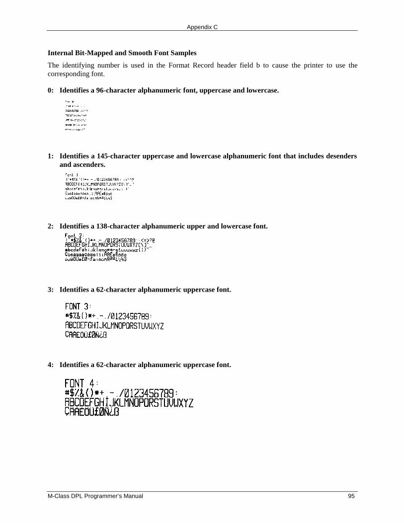
Appendix C
M-Class DPL Programmer’s Manual 95
Internal Bit-Mapped and Smooth Font Samples
The identifying number is used in the Format Record header field b to cause the printer to use thecorresponding font.
0: Identifies a 96-character alphanumeric font, uppercase and lowercase.
1: Identifies a 145-character uppercase and lowercase alphanumeric font that includes desendersand ascenders.
2: Identifies a 138-character alphanumeric upper and lowercase font.
3: Identifies a 62-character alphanumeric uppercase font.
4: Identifies a 62-character alphanumeric uppercase font.
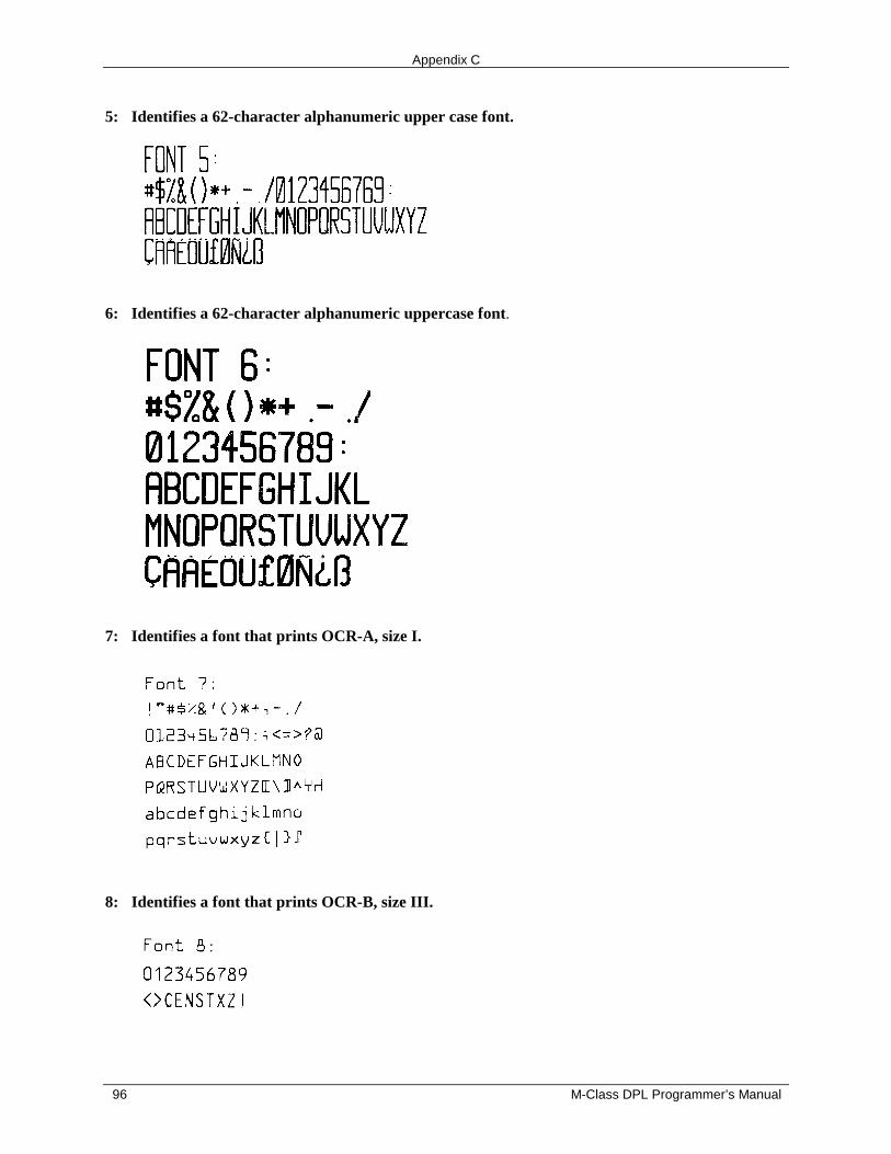
Appendix C
96 M-Class DPL Programmer’s Manual
5: Identifies a 62-character alphanumeric upper case font.
6: Identifies a 62-character alphanumeric uppercase font.
7: Identifies a font that prints OCR-A, size I.
8: Identifies a font that prints OCR-B, size III.
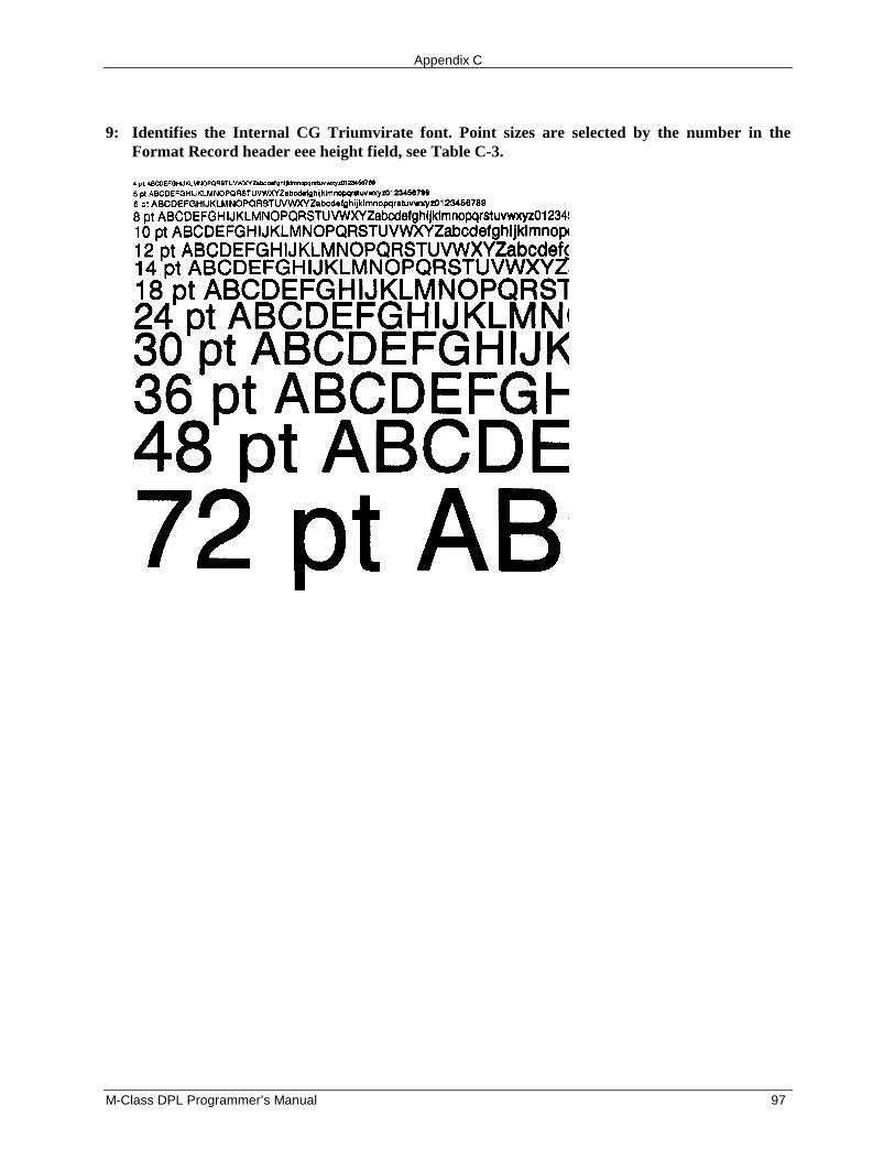
Appendix C
M-Class DPL Programmer’s Manual 97
9: Identifies the Internal CG Triumvirate font. Point sizes are selected by the number in theFormat Record header eee height field, see Table C-3.

Appendix C
98 M-Class DPL Programmer’s Manual
M-Class Programmer’s Manual 99
Appendix D
Error Codes
The following are the most common transmitted error codes:
Lowercase “c”
The printer received a data byte from the host computer that contained a framing error (corrupteddata - usually due to noise).
Uppercase “I”
An invalid command sequence was sent to the printer. The printer did not understand the commandsequence and terminated the command interpreter.
Uppercase “R”
This code is sent every time the printer is turned ‘On’, signaling a hardware reset.
Uppercase “T”
This code signals a software reset. A software reset is made by sending the command sequence to theprinter or by performing a reset using the front panel buttons.
Lowercase “v”
There is an input buffer overflow situation, caused when an overflow of data is sent to the printer.

Appendix D
100 M-Class DPL Programmer’s Manual
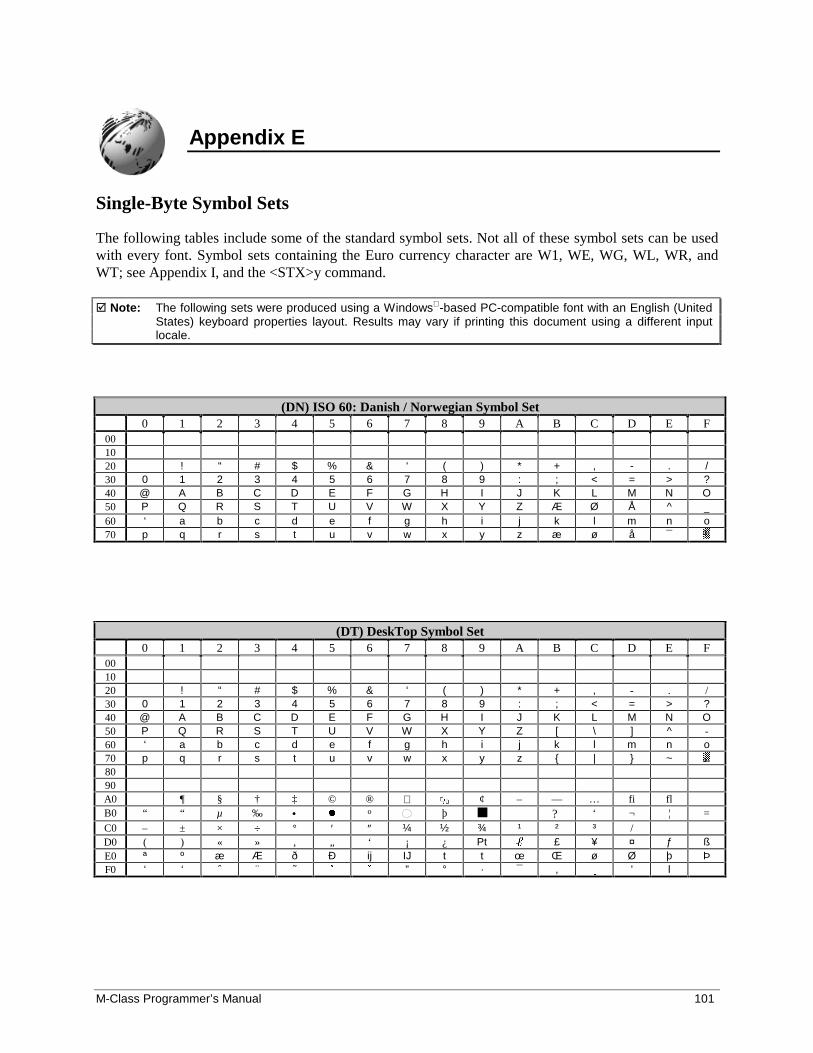
M-Class Programmer’s Manual 101
Appendix E
Single-Byte Symbol Sets
The following tables include some of the standard symbol sets. Not all of these symbol sets can be usedwith every font. Symbol sets containing the Euro currency character are W1, WE, WG, WL, WR, andWT; see Appendix I, and the <STX>y command.
� Note: The following sets were produced using a Windows -based PC-compatible font with an English (UnitedStates) keyboard properties layout. Results may vary if printing this document using a different inputlocale.
(DN) ISO 60: Danish / Norwegian Symbol Set0 1 2 3 4 5 6 7 8 9 A B C D E F
001020 ! “ # $ % & ‘ ( ) * + , - . /30 0 1 2 3 4 5 6 7 8 9 : ; < = > ?40 @ A B C D E F G H I J K L M N O50 P Q R S T U V W X Y Z Æ Ø Å ^ _60 ‘ a b c d e f g h i j k l m n o70 p q r s t u v w x y z æ ø å ¯
(DT) DeskTop Symbol Set0 1 2 3 4 5 6 7 8 9 A B C D E F
001020 ! “ # $ % & ‘ ( ) * + , - . /30 0 1 2 3 4 5 6 7 8 9 : ; < = > ?40 @ A B C D E F G H I J K L M N O50 P Q R S T U V W X Y Z [ \ ] ^ -60 ‘ a b c d e f g h i j k l m n o70 p q r s t u v w x y z { | } ~8090A0 ¶ § † ‡ © ® ¢ – — … fi flB0 “ “ µ ‰ • � o þ ■ ? ‘ ¬ ¦ =
C0 – ± × ÷ ° ′ ″ ¼ ½ ¾ ¹ ² ³ /D0 ( ) « » ‚ „ ‘ ¡ ¿ Pt £ ¥ ¤ ƒ ßE0 ª º æ Æ ð Ð ij IJ t t œ Œ ø Ø þ ÞF0 ‘ ‘ ˆ ¨ ˜ � � ” ° · ¯ , � ' l
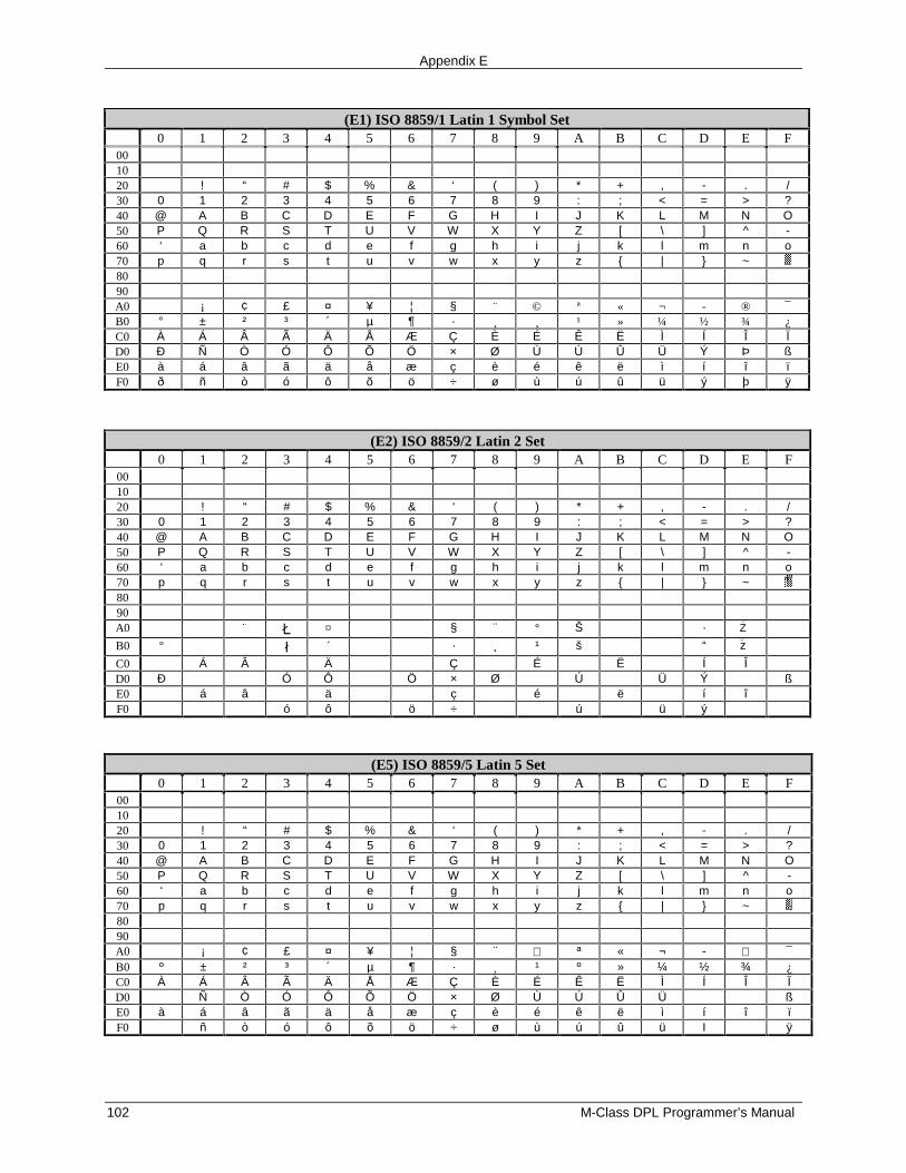
Appendix E
102 M-Class DPL Programmer’s Manual
(E1) ISO 8859/1 Latin 1 Symbol Set0 1 2 3 4 5 6 7 8 9 A B C D E F
001020 ! “ # $ % & ‘ ( ) * + , - . /30 0 1 2 3 4 5 6 7 8 9 : ; < = > ?40 @ A B C D E F G H I J K L M N O50 P Q R S T U V W X Y Z [ \ ] ^ -60 ‘ a b c d e f g h i j k l m n o70 p q r s t u v w x y z { | } ~8090A0 ¡ ¢ £ ¤ ¥ ¦ § ¨ © ª « ¬ - ® ¯B0 ° ± ² ³ ´ µ ¶ · ¸ ¸ ¹ » ¼ ½ ¾ ¿C0 À Á Â Ã Ä Å Æ Ç È É Ê Ë Ì Í Î ÏD0 Ð Ñ Ò Ó Ô Õ Ö × Ø Ù Ú Û Ü Ý Þ ßE0 à á â ã ä å æ ç è é ê ë ì í î ïF0 ð ñ ò ó ô õ ö ÷ ø ù ú û ü ý þ ÿ
(E2) ISO 8859/2 Latin 2 Set0 1 2 3 4 5 6 7 8 9 A B C D E F
001020 ! “ # $ % & ‘ ( ) * + , - . /30 0 1 2 3 4 5 6 7 8 9 : ; < = > ?40 @ A B C D E F G H I J K L M N O50 P Q R S T U V W X Y Z [ \ ] ^ -60 ‘ a b c d e f g h i j k l m n o70 p q r s t u v w x y z { | } ~8090A0 � � ¤ § ¨ ° Š · Z
B0 º � ´ · ¸ ¹ š “ z
C0 Á Â Ä Ç É Ë Í ÎD0 Ð Ó Ô Ö × Ø Ú Ü Ý ßE0 á â ä ç é ë í îF0 ó ô ö ÷ ú ü ý
(E5) ISO 8859/5 Latin 5 Set0 1 2 3 4 5 6 7 8 9 A B C D E F
001020 ! “ # $ % & ‘ ( ) * + , - . /30 0 1 2 3 4 5 6 7 8 9 : ; < = > ?40 @ A B C D E F G H I J K L M N O50 P Q R S T U V W X Y Z [ \ ] ^ -60 ‘ a b c d e f g h i j k l m n o70 p q r s t u v w x y z { | } ~8090A0 ¡ ¢ £ ¤ ¥ ¦ § ¨ ª « ¬ - ¯B0 º ± ² ³ ´ µ ¶ · ¸ ¹ º » ¼ ½ ¾ ¿C0 À Á Â Ã Ä Å Æ Ç È É Ê Ë Ì Í Î ÏD0 Ñ Ò Ó Ô Õ Ö × Ø Ù Ú Û Ü ßE0 à á â ã ä å æ ç è é ê ë ì í î ïF0 ñ ò ó ô õ ö ÷ ø ù ú û ü I ÿ
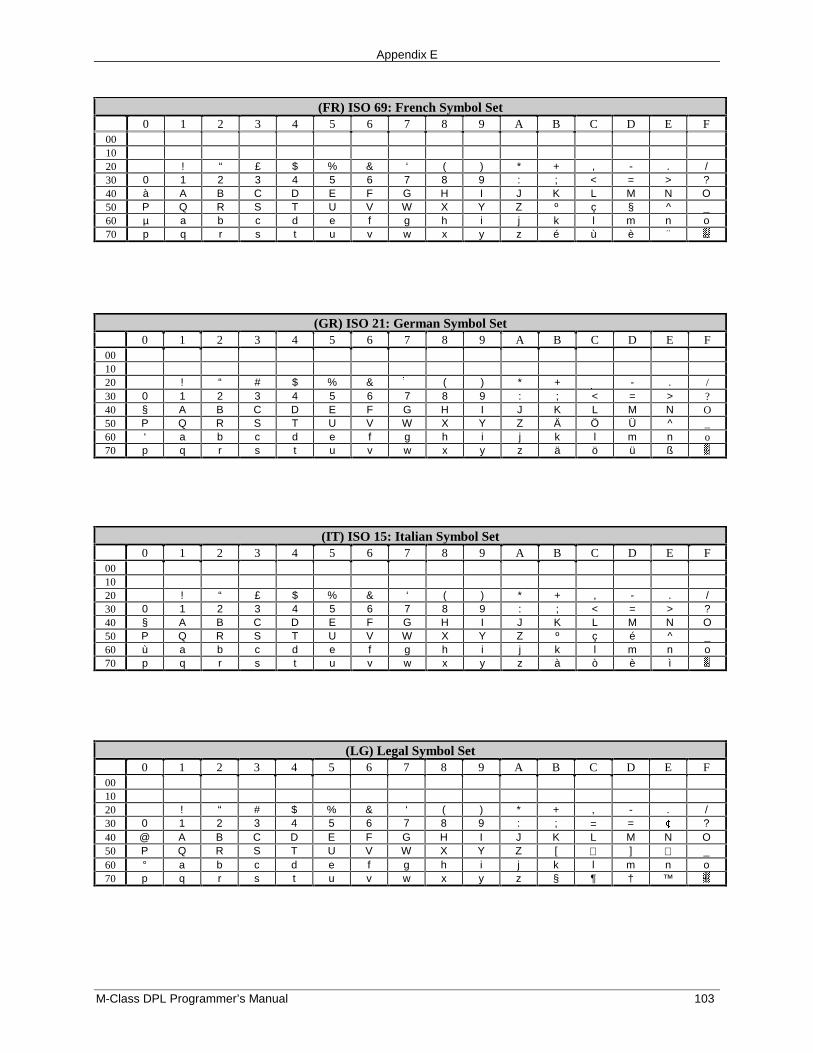
Appendix E
M-Class DPL Programmer’s Manual 103
(FR) ISO 69: French Symbol Set0 1 2 3 4 5 6 7 8 9 A B C D E F
001020 ! “ £ $ % & ‘ ( ) * + , - . /30 0 1 2 3 4 5 6 7 8 9 : ; < = > ?40 à A B C D E F G H I J K L M N O50 P Q R S T U V W X Y Z º ç § ^ _60 µ a b c d e f g h i j k l m n o70 p q r s t u v w x y z é ù è ¨
(GR) ISO 21: German Symbol Set0 1 2 3 4 5 6 7 8 9 A B C D E F
001020 ! “ # $ % & ( ) * + - . /30 0 1 2 3 4 5 6 7 8 9 : ; < = > ?40 § A B C D E F G H I J K L M N O50 P Q R S T U V W X Y Z Ä Ö Ü ^ _60 ‘ a b c d e f g h i j k l m n o70 p q r s t u v w x y z ä ö ü ß
(IT) ISO 15: Italian Symbol Set0 1 2 3 4 5 6 7 8 9 A B C D E F
001020 ! “ £ $ % & ‘ ( ) * + , - . /30 0 1 2 3 4 5 6 7 8 9 : ; < = > ?40 § A B C D E F G H I J K L M N O50 P Q R S T U V W X Y Z º ç é ^ _60 ù a b c d e f g h i j k l m n o70 p q r s t u v w x y z à ò è ì
(LG) Legal Symbol Set0 1 2 3 4 5 6 7 8 9 A B C D E F
001020 ! “ # $ % & ‘ ( ) * + , - . /30 0 1 2 3 4 5 6 7 8 9 : ; = = � ?40 @ A B C D E F G H I J K L M N O50 P Q R S T U V W X Y Z [ ] _60 ° a b c d e f g h i j k l m n o70 p q r s t u v w x y z § ¶ † ™
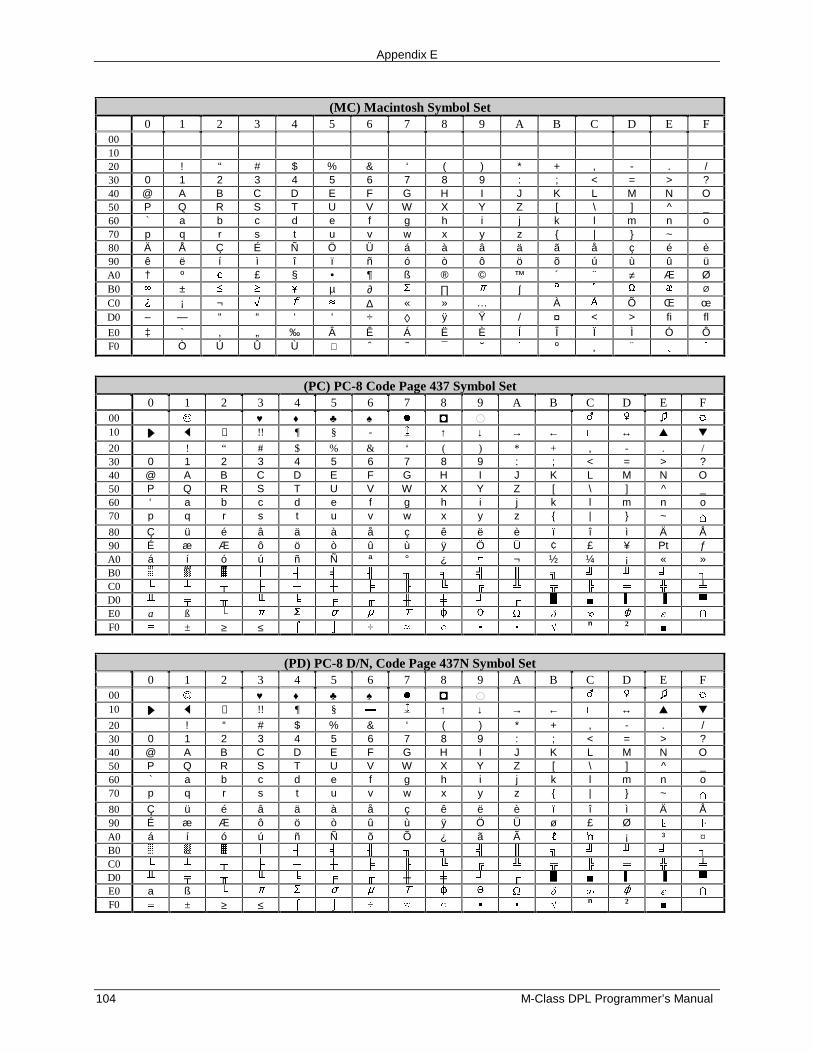
Appendix E
104 M-Class DPL Programmer’s Manual
(MC) Macintosh Symbol Set0 1 2 3 4 5 6 7 8 9 A B C D E F
001020 ! “ # $ % & ‘ ( ) * + , - . /30 0 1 2 3 4 5 6 7 8 9 : ; < = > ?40 @ A B C D E F G H I J K L M N O50 P Q R S T U V W X Y Z [ \ ] ^ _60 ` a b c d e f g h i j k l m n o70 p q r s t u v w x y z { | } ~80 Ä Å Ç É Ñ Ö Ü á à â ä ã å ç é è90 ê ë í ì î ï ñ ó ò ô ö õ ú ù û üA0 † º � £ § • ¶ ß ® © ™ ´ ¨ ≠ Æ ØB0 � ± � � � µ ∂ ∏ � ∫ � � � Ø
C0 � ¡ ¬ � � ∆ « » … À Õ Œ œD0 – — “ “ ‘ ‘ ÷ ◊ ÿ Ÿ / ¤ < > fi fl
E0 ‡ ` ‚ „ ‰ Â Ê Á Ë È Í Î Ï Ì Ó ÔF0 Ò Ú Û Ù ˆ ˜ ¯ � � º ¸ ¨ � �
(PC) PC-8 Code Page 437 Symbol Set0 1 2 3 4 5 6 7 8 9 A B C D E F
00 � ♥ ♦ ♣ ♠ � �10 ↕ !! ¶ § - ↑ ↓ → ← ↔ ▲ ▼
20 ! “ # $ % & ‘ ( ) * + , - . /30 0 1 2 3 4 5 6 7 8 9 : ; < = > ?40 @ A B C D E F G H I J K L M N O50 P Q R S T U V W X Y Z [ \ ] ^ _60 ‘ a b c d e f g h i j k l m n o70 p q r s t u v w x y z { | } ~
80 Ç ü é â ä à å ç ê ë è ï î ì Ä Å90 É æ Æ ô ö ò û ù ÿ Ö Ü ¢ £ ¥ Pt ƒA0 á í ó ú ñ Ñ ª ° ¿ ¬ ½ ¼ ¡ « »B0C0D0E0 a ß � � � � �
F0 ± ≥ ≤ ÷ � �n 2
(PD) PC-8 D/N, Code Page 437N Symbol Set0 1 2 3 4 5 6 7 8 9 A B C D E F
00 � ♥ ♦ ♣ ♠ � �10 ↕ !! ¶ § ↑ ↓ → ← ↔ ▲ ▼
20 ! “ # $ % & ‘ ( ) * + , - . /30 0 1 2 3 4 5 6 7 8 9 : ; < = > ?40 @ A B C D E F G H I J K L M N O50 P Q R S T U V W X Y Z [ \ ] ^ _60 ` a b c d e f g h i j k l m n o70 p q r s t u v w x y z { | } ~
80 Ç ü é â ä à å ç ê ë è ï î ì Ä Å90 É æ Æ ô ö ò û ù ÿ Ö Ü ø £ ØA0 á í ó ú ñ Ñ õ Õ ¿ ã Ã ¡ ³ ¤B0C0D0E0 a ß � � � � �
F0 ± ≥ ≤ ÷ � �n 2
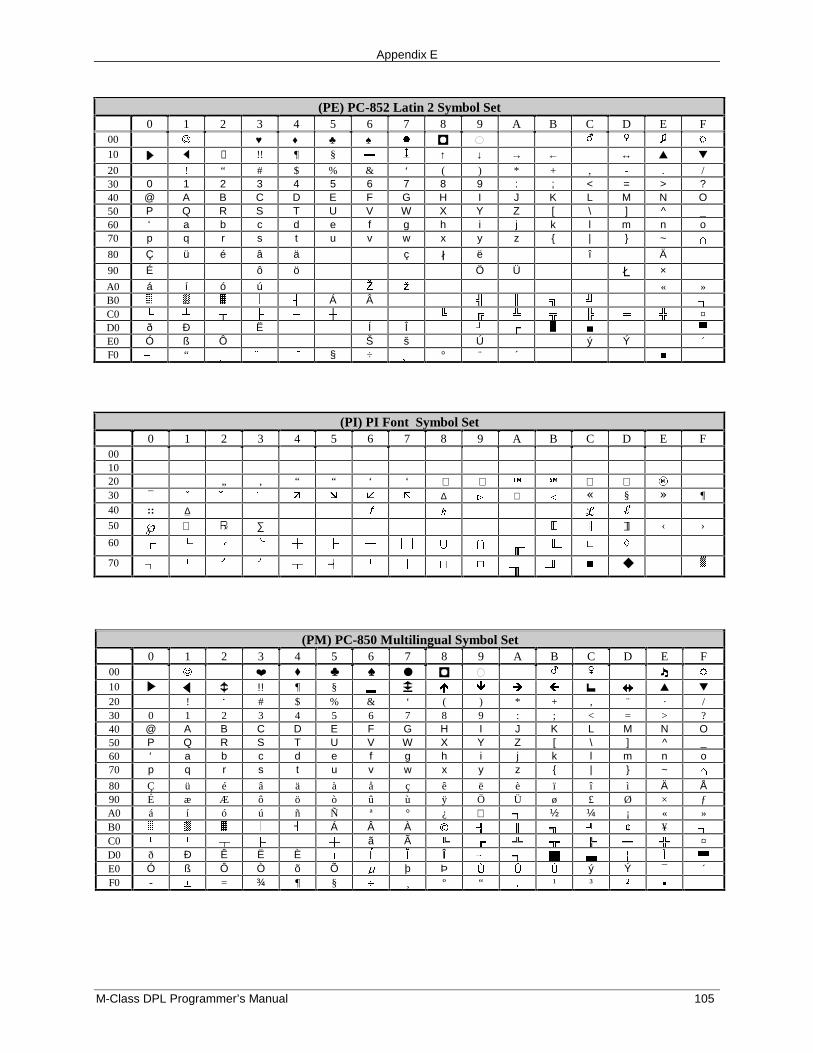
Appendix E
M-Class DPL Programmer’s Manual 105
(PE) PC-852 Latin 2 Symbol Set0 1 2 3 4 5 6 7 8 9 A B C D E F
00 � ♥ ♦ ♣ ♠ � �
10 ↕ !! ¶ § ↑ ↓ → ← ↔ ▲ ▼
20 ! “ # $ % & ‘ ( ) * + , - . /30 0 1 2 3 4 5 6 7 8 9 : ; < = > ?40 @ A B C D E F G H I J K L M N O50 P Q R S T U V W X Y Z [ \ ] ^ _60 ‘ a b c d e f g h i j k l m n o70 p q r s t u v w x y z { | } ~
80 Ç ü é â ä ç � ë î Ä
90 É ô ö Ö Ü � ×
A0 á í ó ú � � « »B0 Á ÂC0 ¤D0 ð Ð Ë Í ÎE0 Ó ß Ô Š š Ú ý Ý ´F0 “ �� § ÷ ° ¨ ´ �
(PI) PI Font Symbol Set0 1 2 3 4 5 6 7 8 9 A B C D E F
001020 „ ‚ “ “ ‘ ‘ ⟨ ⟩ � 30 ¯ � � � � � ∆ � ∇ � � § � ¶40 :: ∆ � �
50 ℘ ∑ ‹ ›
60 � � �
70 ◆
(PM) PC-850 Multilingual Symbol Set0 1 2 3 4 5 6 7 8 9 A B C D E F
00 � ❤ ♦ ♣ ♠ ● �
10 !! ¶ § � � ▲ ▼
20 ! � # $ % & ‘ ( ) * + ‚ ¨ · /30 0 1 2 3 4 5 6 7 8 9 : ; < = > ?40 @ A B C D E F G H I J K L M N O50 P Q R S T U V W X Y Z [ \ ] ^ _60 ‘ a b c d e f g h i j k l m n o70 p q r s t u v w x y z { | } ~
80 Ç ü é â ä à å ç ê ë è ï î ì Ä Å90 É æ Æ ô ö ò û ù ÿ Ö Ü ø £ Ø × ƒA0 á í ó ú ñ Ñ ª ° ¿ ½ ¼ ¡ « »B0 Á Â À � � ¥C0 ã Ã ¤D0 ð Ð Ê Ë È Î E0 Ó ß Ô Ò õ Õ þ Þ � � ý Ý ¯ ´F0 - � = ¾ ¶ § � ¸ º “ � ¹ ³ �
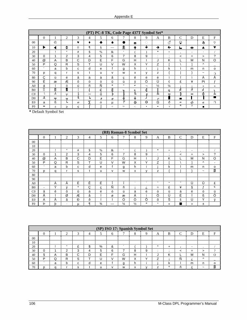
Appendix E
106 M-Class DPL Programmer’s Manual
(PT) PC-8 TK, Code Page 437T Symbol Set*0 1 2 3 4 5 6 7 8 9 A B C D E F
00 � ♦ ♣ ♠ ● �
10 !! ¶ § — � � ▲ ▼
20 ! ″ # $ % & ‘ ( ) * + ‚ - · /30 0 1 2 3 4 5 6 7 8 9 : ; < = > ?40 @ A B C D E F G H I J K L M N O50 P Q R S T U V W X Y Z [ \ ] ^ _60 ‘ a b c d e f g h i j k l m n o70 p q r s t u v w x y z { | } ~
80 Ç ü é â ä à å ç ê ë è ï î ì Ä Å90 É æ Æ ô ö ò û ù ÿ Ö Ü ¢ £ ¥ Pt ƒA0 á í ó ú ñ Ñ ª ° ¬ ½ ¼ ¡ ¡ « »B0C0D0E0 a ß � µ � �
F0 ± ≥ ≤ ÷ � �n 2
* Default Symbol Set
(R8) Roman-8 Symbol Set0 1 2 3 4 5 6 7 8 9 A B C D E F
001020 ! “ # $ % & ‘ ( ) * + , - . /30 0 1 2 3 4 5 6 7 8 9 : ; < = > ?40 @ A B C D E F G H I J K L M N O50 P Q R S T U V W X Y Z [ \ ] ^ -60 ‘ a b c d e f g h i j k l m n o70 p q r s t u v w x y z { | } ~8090A0 À Â È Ê Ë Î Ï ` ˆ “ ˜ Ù Û £B0 - Ý ý º Ç ç Ñ ñ ¡ ¿ ¤ £ ¥ § ƒ �
C0 â ê ô û á é ó ú à è ò ù ä ë ö üD0 Å î Ø Æ å Í ø æ Ä ì Ö Ü É Ï ß ÔE0 Á Ã ã Ð ð Í Ì Ó Ò Õ õ Š š Ú Ÿ ÿF0 Þ þ · µ ¶ ¾ — ¼ ½ ª ° « ■ » ±
(SP) ISO 17: Spanish Symbol Set0 1 2 3 4 5 6 7 8 9 A B C D E F
001020 ! “ £ $ % & ´ ( ) * + - . /30 0 1 2 3 4 5 6 7 8 9 : ; < = > ?40 § A B C D E F G H I J K L M N O50 P Q R S T U V W X Y Z ¡ Ñ ¿ ^ _60 ` a b c d e f g h i j k l m n o70 p q r s t u v w x y z º ñ ç ~
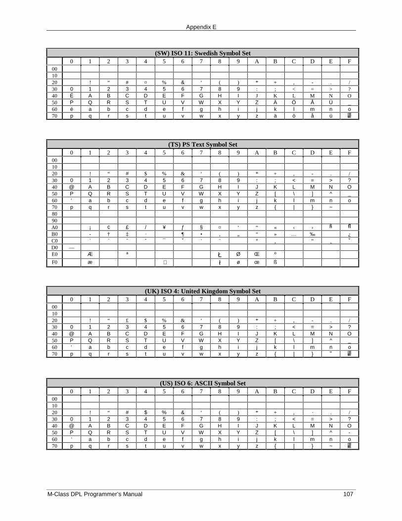
Appendix E
M-Class DPL Programmer’s Manual 107
(SW) ISO 11: Swedish Symbol Set0 1 2 3 4 5 6 7 8 9 A B C D E F
001020 ! “ # ¤ % & ‘ ( ) * + , - . /30 0 1 2 3 4 5 6 7 8 9 : ; < = > ?40 É A B C D E F G H I J K L M N O50 P Q R S T U V W X Y Z Ä Ö Å Ü _60 é a b c d e f g h i j k l m n o70 p q r s t u v w x y z ä ö å ü
(TS) PS Text Symbol Set0 1 2 3 4 5 6 7 8 9 A B C D E F
001020 ! “ # $ % & ‘ ( ) * + , - . /30 0 1 2 3 4 5 6 7 8 9 : ; < = > ?40 @ A B C D E F G H I J K L M N O50 P Q R S T U V W X Y Z [ \ ] ^ _60 ‘ a b c d e f g h i j k l m n o70 p q r s t u v w x y z { | } ~8090A0 ¡ ¢ £ / ¥ ƒ § ¤ ‘ “ « ‹ › � �
B0 - † ‡ · ¶ • , „ “ » … ‰ ¿C0 ` ´ ˆ ˜ ¯ � ¨ ° ¸ “ � �D0 —E0 Æ ª � Ø Œ º
F0 æ � ø œ ß
(UK) ISO 4: United Kingdom Symbol Set0 1 2 3 4 5 6 7 8 9 A B C D E F
001020 ! “ £ $ % & ‘ ( ) * + , - . /30 0 1 2 3 4 5 6 7 8 9 : ; < = > ?40 @ A B C D E F G H I J K L M N O50 P Q R S T U V W X Y Z [ \ ] ^ _60 ‘ a b c d e f g h i j k l m n o70 p q r s t u v w x y z { | }
(US) ISO 6: ASCII Symbol Set0 1 2 3 4 5 6 7 8 9 A B C D E F
001020 ! “ # $ % & ‘ ( ) * + , · . /30 0 1 2 3 4 5 6 7 8 9 : ; < = > ?40 @ A B C D E F G H I J K L M N O50 P Q R S T U V W X Y Z [ \ ] ^ -60 ‘ a b c d e f g h i j k l m n o70 p q r s t u v w x y z { | } ~
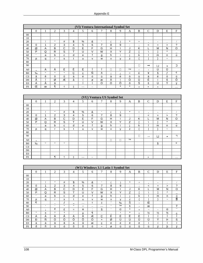
Appendix E
108 M-Class DPL Programmer’s Manual
(VI) Ventura International Symbol Set0 1 2 3 4 5 6 7 8 9 A B C D E F
001020 ! “ # $ % & ‘ ( ) * + , - . /30 0 1 2 3 4 5 6 7 8 9 : ; < = > ?40 @ A B C D E F G H I J K L M N O50 P Q R S T U V W X Y Z [ \ ] ^ _60 ‘ a b c d e f g h i j k l m n o70 p q r s t u v w x y z { | } ~8090 ↵ ➞
A0 „ À Â È Ê Ë Î Ï ™ ‹ › Ú ÛB0 ‰ “ “ º Ç ç Ñ ñ ¡ ¿ ¤ £ ¥ § ƒ �
C0 â ê ô û á é ó ú à è ò ù ä ë ö üD0 Å î Ø Æ å í ø æ Ä ì Ö Ü É ï ß ÔE0 Á à ã Í Ì Ó Ò Õ õ Š š Ú Ÿ ÿF0 Œ œ ¶ † ‡ — – ª º « • » …
(VU) Ventura US Symbol Set0 1 2 3 4 5 6 7 8 9 A B C D E F
001020 ! “ # $ % & ‘ ( ) * + , - . /30 0 1 2 3 4 5 6 7 8 9 : ; < = > ?40 @ A B C D E F G H I J K L M N O50 P Q R S T U V W X Y Z [ \ ] ^ _60 ‘ a b c d e f g h i j k l m n o70 p q r s t u v w x y z { | } ~8090 ↵A0 „ ™B0 ‰ “ “ º § �
C0D0E0F0 ¶ † ‡ — – • …
(W1) Windows 3.1 Latin 1 Symbol Set0 1 2 3 4 5 6 7 8 9 A B C D E F
001020 ! “ # $ % & ‘ ( ) * + , - . /30 0 1 2 3 4 5 6 7 8 9 : ; < = > ?40 @ A B C D E F G H I J K L M N O50 P Q R S T U V W X Y Z [ \ ] ^ _60 ‘ a b c d e f g h i j k l m n o70 p q r s t u v w x y z { | } ~80 ‚ ƒ „ … † ‡ ˆ ‰ Š ‹ Œ90 ‘ ‘ “ “ • – — ˜ ™ š › œ ŸA0 ¡ � £ ¤ ¥ ¦ § ¨ © ª « ¬ - ® ¯B0 ° ± ² ³ ´ µ ¶ · ¸ ¹ º » ¼ ½ ¾ ¿C0 À Á Â Ã Ä Å Æ Ç È É Ê Ë Ì Í Î ÏD0 Ð Ñ Ò Ó Ô Õ Ö × Ø Ù Ú Û Ü Ý Þ ßE0 à á â ã ä å æ ç è é ê ë ì í î ïF0 ð ñ ò ó ô õ ö ÷ ø ù ú û ü ý þ ÿ
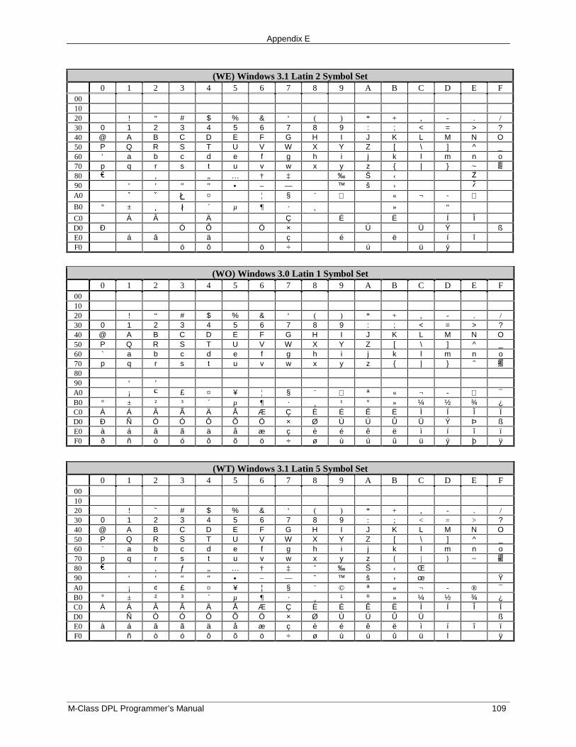
Appendix E
M-Class DPL Programmer’s Manual 109
(WE) Windows 3.1 Latin 2 Symbol Set0 1 2 3 4 5 6 7 8 9 A B C D E F
001020 ! “ # $ % & ‘ ( ) * + , - . /30 0 1 2 3 4 5 6 7 8 9 : ; < = > ?40 @ A B C D E F G H I J K L M N O50 P Q R S T U V W X Y Z [ \ ] ^ _60 ‘ a b c d e f g h i j k l m n o70 p q r s t u v w x y z { | } ~80 ‚ „ … † ‡ ‰ Š ‹ �
90 ‘ ‘ “ “ • – — ™ š › �
A0 � � � ¤ ¦ § ¨ « ¬ - B0 º ± � � ´ µ ¶ · ¸ » “
C0 Á Â Ä Ç É Ë Í ÎD0 Ð Ó Ô Ö × Ú Ü Ý ßE0 á â ä ç é ë í îF0 ó ô ö ÷ ú ü ý
(WO) Windows 3.0 Latin 1 Symbol Set0 1 2 3 4 5 6 7 8 9 A B C D E F
001020 ! “ # $ % & ‘ ( ) * + , - . /30 0 1 2 3 4 5 6 7 8 9 : ; < = > ?40 @ A B C D E F G H I J K L M N O50 P Q R S T U V W X Y Z [ \ ] ^ _60 ` a b c d e f g h i j k l m n o70 p q r s t u v w x y z { | } ˜8090 ‘ ’A0 ¡ � £ ¤ ¥ ¦ § ¨ ª « ¬ - ¯B0 ° ± ² ³ ´ µ ¶ · ¸ ¹ º » ¼ ½ ¾ ¿C0 À Á Â Ã Ä Å Æ Ç È É Ê Ë Ì Í Î ÏD0 Ð Ñ Ò Ó Ô Õ Ö × Ø Ù Ú Û Ü Ý Þ ßE0 à á â ã ä å æ ç è é ê ë ì í î ïF0 ð ñ ò ó ô õ ö ÷ ø ù ú û ü ý þ ÿ
(WT) Windows 3.1 Latin 5 Symbol Set0 1 2 3 4 5 6 7 8 9 A B C D E F
001020 ! ˜ # $ % & ‘ ( ) * + ‚ - . /30 0 1 2 3 4 5 6 7 8 9 : ; < = > ?40 @ A B C D E F G H I J K L M N O50 P Q R S T U V W X Y Z [ \ ] ^ _60 ` a b c d e f g h i j k l m n o70 p q r s t u v w x y z { | } ~80 , ƒ „ … † ‡ ˆ ‰ Š ‹ Œ90 ‘ ‘ “ “ • – — ˜ ™ š › œ ŸA0 ¡ ¢ £ ¤ ¥ ¦ § ¨ © ª « ¬ - ® ¯B0 ° ± ² ³ ´ µ ¶ · ¸ ¹ º » ¼ ½ ¾ ¿C0 À Á Â Ã Ä Å Æ Ç È É Ê Ë Ì Í Î ÏD0 Ñ Ò Ó Ô Õ Ö × Ø Ù Ú Û Ü ßE0 à á â ã ä å æ ç è é ê ë ì í î ïF0 ñ ò ó ô õ ö ÷ ø ù ú û ü l ÿ

Appendix E
110 M-Class DPL Programmer’s Manual
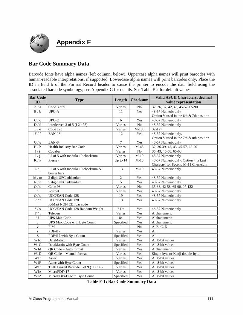
M-Class Programmer’s Manual 111
Appendix F
Bar Code Summary Data
Barcode fonts have alpha names (left column, below). Uppercase alpha names will print barcodes withhuman-readable interpretations, if supported. Lowercase alpha names will print barcodes only. Place theID in field b of the Format Record header to cause the printer to encode the data field using theassociated barcode symbology; see Appendix G for details. See Table F-2 for default values.
Bar CodeID Type Length Checksum
Valid ASCII Characters, decimalvalue representation
A / a Code 3 of 9 Varies No 32, 36, 37, 42, 43, 45-57, 65-90B / b UPC-A 11 Yes 48-57 Numeric only
Option V used in the 6th & 7th positionC / c UPC-E 6 Yes 48-57 Numeric onlyD / d Interleaved 2 of 5 (I 2 of 5) Varies No 48-57 Numeric onlyE / e Code 128 Varies M-103 32-127F / f EAN-13 12 Yes 48-57 Numeric only.
Option V used in the 7th & 8th positionG / g EAN-8 7 Yes 48-57 Numeric onlyH / h Health Industry Bar Code Varies M-43 32, 36-39, 42, 43, 45-57, 65-90I / i Codabar Varies No 36, 43, 45-58, 65-68J / j I 2 of 5 with modulo 10 checksum Varies M-10 48-57 Numeric only
K / k Plessey Up to 14 M-10 48-57 Numeric only. Option + is LastCharacter for Second M-11 Checksum
L / l I 2 of 5 with modulo 10 checksum &bearer bars
13 M-10 48-57 Numeric only
M / m 2 digit UPC addendum 2 Yes 48-57 Numeric onlyN / n 5 digit UPC addendum 5 Yes 48-57 Numeric onlyO / o Code 93 Varies No 35-38, 42-58, 65-90, 97-122
p Postnet Varies Yes 48-57 Numeric onlyQ / q UCC/EAN Code 128 19 Yes 48-57 Numeric onlyR / r UCC/EAN Code 128
K-Mart NON EDI bar code18 Yes 48-57 Numeric only
S / s UCC/EAN Code 128 Random Weight 34 + Yes 48-57 Numeric onlyT / t Telepen Varies Yes AlphanumericU UPS MaxiCode 84 Yes Alphanumericu UPS MaxiCode with Byte Count Specified Yes Alphanumericv FIM 1 No A, B, C, Dz PDF417 Varies Yes AllZ PDF417 with Byte Count Specified Yes All
W1c DataMatrix Varies Yes All 8-bit valuesW1C DataMatrix with Byte Count Specified Yes All 8-bit valuesW1d QR Code – Auto format Varies Yes AlphanumericW1D QR Code – Manual format Varies Yes Single-byte or Kanji double-byteW1f Aztec Varies Yes All 8-bit valuesW1F Aztec with Byte Count Specified Yes All 8-bit valuesW1t TLIF Linked Barcode 3 of 9 (TLC39) Varies Yes All 8-bit valuesW1z MicroPDF417 Varies Yes All 8-bit valuesW1Z MicroPDF417 with Byte Count Specified Yes All 8-bit values
Table F-1: Bar Code Summary Data
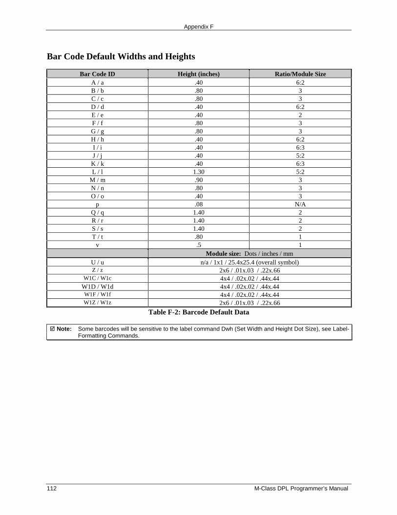
Appendix F
112 M-Class DPL Programmer’s Manual
Bar Code Default Widths and Heights
Bar Code ID Height (inches) Ratio/Module SizeA / a .40 6:2B / b .80 3C / c .80 3D / d .40 6:2E / e .40 2F / f .80 3G / g .80 3H / h .40 6:2I / i .40 6:3J / j .40 5:2
K / k .40 6:3L / l 1.30 5:2
M / m .90 3N / n .80 3O / o .40 3
p .08 N/AQ / q 1.40 2R / r 1.40 2S / s 1.40 2T / t .80 1
v .5 1Module size: Dots / inches / mm
U / u n/a / 1x1 / 25.4x25.4 (overall symbol)Z / z 2x6 / .01x.03 / .22x.66
W1C / W1c 4x4 / .02x.02 / .44x.44W1D / W1d 4x4 / .02x.02 / .44x.44W1F / W1f 4x4 / .02x.02 / .44x.44W1Z / W1z 2x6 / .01x.03 / .22x.66
Table F-2: Barcode Default Data
� Note: Some barcodes will be sensitive to the label command Dwh (Set Width and Height Dot Size), see Label-Formatting Commands.
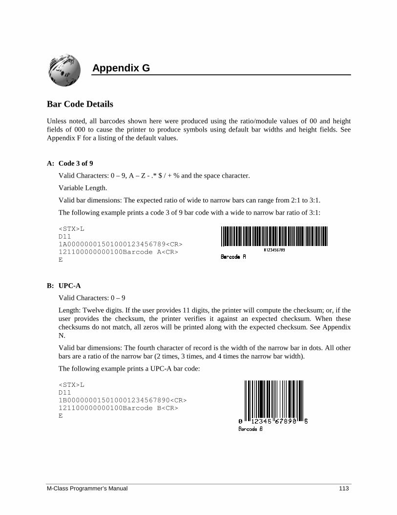
M-Class Programmer’s Manual 113
Appendix G
Bar Code Details
Unless noted, all barcodes shown here were produced using the ratio/module values of 00 and heightfields of 000 to cause the printer to produce symbols using default bar widths and height fields. SeeAppendix F for a listing of the default values.
A: Code 3 of 9
Valid Characters: 0 – 9, A – Z - .* $ / + % and the space character.
Variable Length.
Valid bar dimensions: The expected ratio of wide to narrow bars can range from 2:1 to 3:1.
The following example prints a code 3 of 9 bar code with a wide to narrow bar ratio of 3:1:
<STX>LD111A00000001501000123456789<CR>121100000000100Barcode A<CR>E
B: UPC-A
Valid Characters: 0 – 9
Length: Twelve digits. If the user provides 11 digits, the printer will compute the checksum; or, if theuser provides the checksum, the printer verifies it against an expected checksum. When thesechecksums do not match, all zeros will be printed along with the expected checksum. See AppendixN.
Valid bar dimensions: The fourth character of record is the width of the narrow bar in dots. All otherbars are a ratio of the narrow bar (2 times, 3 times, and 4 times the narrow bar width).
The following example prints a UPC-A bar code:
<STX>LD111B000000015010001234567890<CR>121100000000100Barcode B<CR>E
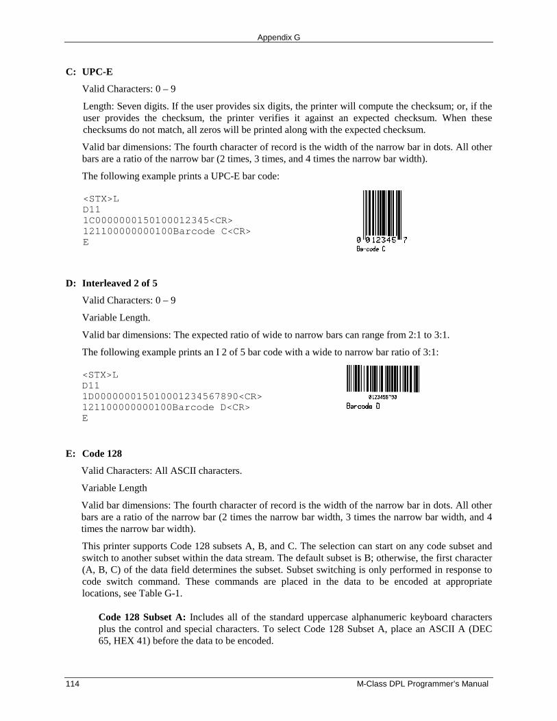
Appendix G
114 M-Class DPL Programmer’s Manual
C: UPC-E
Valid Characters: 0 – 9
Length: Seven digits. If the user provides six digits, the printer will compute the checksum; or, if theuser provides the checksum, the printer verifies it against an expected checksum. When thesechecksums do not match, all zeros will be printed along with the expected checksum.
Valid bar dimensions: The fourth character of record is the width of the narrow bar in dots. All otherbars are a ratio of the narrow bar (2 times, 3 times, and 4 times the narrow bar width).
The following example prints a UPC-E bar code:
<STX>LD111C0000000150100012345<CR>121100000000100Barcode C<CR>E
D: Interleaved 2 of 5
Valid Characters: 0 – 9
Variable Length.
Valid bar dimensions: The expected ratio of wide to narrow bars can range from 2:1 to 3:1.
The following example prints an I 2 of 5 bar code with a wide to narrow bar ratio of 3:1:
<STX>LD111D000000015010001234567890<CR>121100000000100Barcode D<CR>E
E: Code 128
Valid Characters: All ASCII characters.
Variable Length
Valid bar dimensions: The fourth character of record is the width of the narrow bar in dots. All otherbars are a ratio of the narrow bar (2 times the narrow bar width, 3 times the narrow bar width, and 4times the narrow bar width).
This printer supports Code 128 subsets A, B, and C. The selection can start on any code subset andswitch to another subset within the data stream. The default subset is B; otherwise, the first character(A, B, C) of the data field determines the subset. Subset switching is only performed in response tocode switch command. These commands are placed in the data to be encoded at appropriatelocations, see Table G-1.
Code 128 Subset A: Includes all of the standard uppercase alphanumeric keyboard charactersplus the control and special characters. To select Code 128 Subset A, place an ASCII A (DEC65, HEX 41) before the data to be encoded.
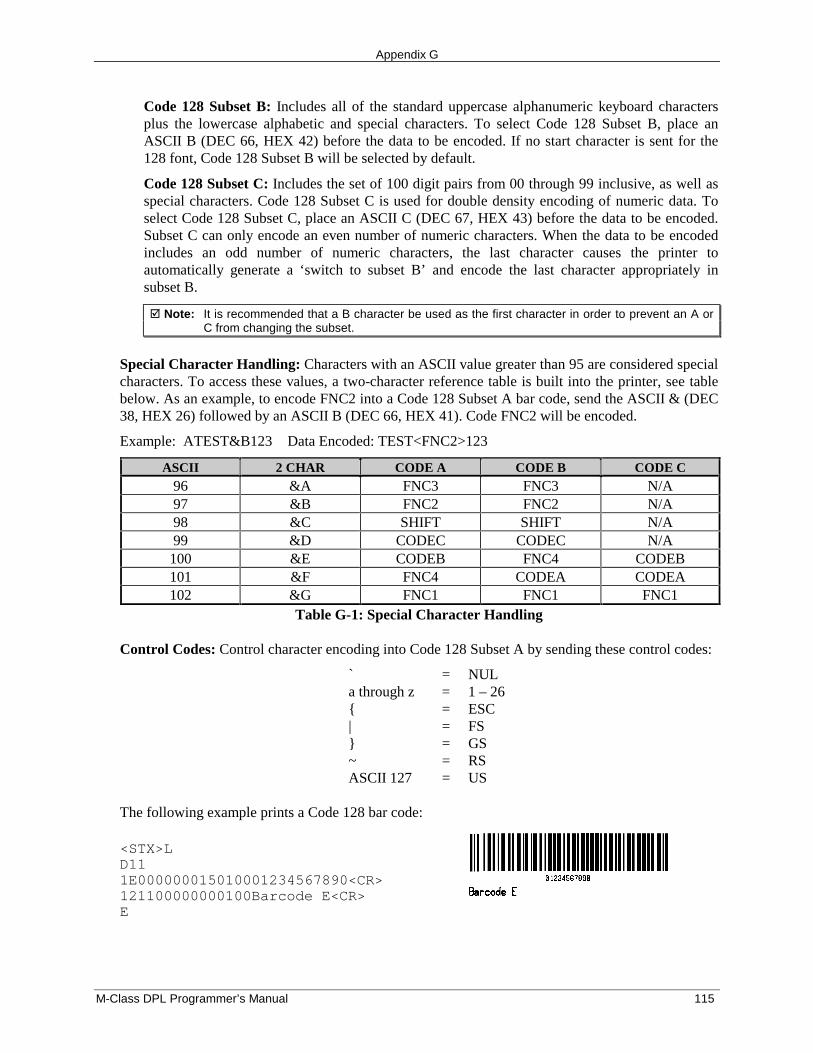
Appendix G
M-Class DPL Programmer’s Manual 115
Code 128 Subset B: Includes all of the standard uppercase alphanumeric keyboard charactersplus the lowercase alphabetic and special characters. To select Code 128 Subset B, place anASCII B (DEC 66, HEX 42) before the data to be encoded. If no start character is sent for the128 font, Code 128 Subset B will be selected by default.
Code 128 Subset C: Includes the set of 100 digit pairs from 00 through 99 inclusive, as well asspecial characters. Code 128 Subset C is used for double density encoding of numeric data. Toselect Code 128 Subset C, place an ASCII C (DEC 67, HEX 43) before the data to be encoded.Subset C can only encode an even number of numeric characters. When the data to be encodedincludes an odd number of numeric characters, the last character causes the printer toautomatically generate a ‘switch to subset B’ and encode the last character appropriately insubset B.
� Note: It is recommended that a B character be used as the first character in order to prevent an A orC from changing the subset.
Special Character Handling: Characters with an ASCII value greater than 95 are considered specialcharacters. To access these values, a two-character reference table is built into the printer, see tablebelow. As an example, to encode FNC2 into a Code 128 Subset A bar code, send the ASCII & (DEC38, HEX 26) followed by an ASCII B (DEC 66, HEX 41). Code FNC2 will be encoded.
Example: ATEST&B123 Data Encoded: TEST<FNC2>123
ASCII 2 CHAR CODE A CODE B CODE C96 &A FNC3 FNC3 N/A97 &B FNC2 FNC2 N/A98 &C SHIFT SHIFT N/A99 &D CODEC CODEC N/A100 &E CODEB FNC4 CODEB101 &F FNC4 CODEA CODEA102 &G FNC1 FNC1 FNC1
Table G-1: Special Character Handling
Control Codes: Control character encoding into Code 128 Subset A by sending these control codes:
` = NULa through z = 1 – 26{ = ESC| = FS} = GS~ = RSASCII 127 = US
The following example prints a Code 128 bar code:
<STX>LD111E000000015010001234567890<CR>121100000000100Barcode E<CR>E
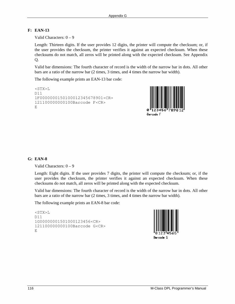
Appendix G
116 M-Class DPL Programmer’s Manual
F: EAN-13
Valid Characters: 0 – 9
Length: Thirteen digits. If the user provides 12 digits, the printer will compute the checksum; or, ifthe user provides the checksum, the printer verifies it against an expected checksum. When thesechecksums do not match, all zeros will be printed along with the expected checksum. See AppendixQ.
Valid bar dimensions: The fourth character of record is the width of the narrow bar in dots. All otherbars are a ratio of the narrow bar (2 times, 3 times, and 4 times the narrow bar width).
The following example prints an EAN-13 bar code:
<STX>LD111F0000000150100012345678901<CR>121100000000100Barcode F<CR>E
G: EAN-8
Valid Characters: 0 – 9
Length: Eight digits. If the user provides 7 digits, the printer will compute the checksum; or, if theuser provides the checksum, the printer verifies it against an expected checksum. When thesechecksums do not match, all zeros will be printed along with the expected checksum.
Valid bar dimensions: The fourth character of record is the width of the narrow bar in dots. All otherbars are a ratio of the narrow bar (2 times, 3 times, and 4 times the narrow bar width).
The following example prints an EAN-8 bar code:
<STX>LD111G00000001501000123456<CR>121100000000100Barcode G<CR>E
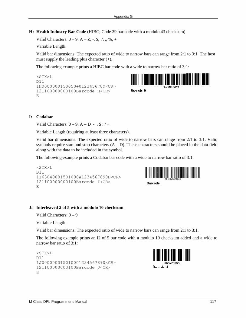
Appendix G
M-Class DPL Programmer’s Manual 117
H: Health Industry Bar Code (HIBC; Code 39 bar code with a modulo 43 checksum)
Valid Characters: 0 – 9, A – Z, -, $, /, ., %, +
Variable Length.
Valid bar dimensions: The expected ratio of wide to narrow bars can range from 2:1 to 3:1. The hostmust supply the leading plus character (+).
The following example prints a HIBC bar code with a wide to narrow bar ratio of 3:1:
<STX>LD111H0000000150050+0123456789<CR>121100000000100Barcode H<CR>E
I: Codabar
Valid Characters: 0 – 9, A – D - . $ : / +
Variable Length (requiring at least three characters).
Valid bar dimensions: The expected ratio of wide to narrow bars can range from 2:1 to 3:1. Validsymbols require start and stop characters (A – D). These characters should be placed in the data fieldalong with the data to be included in the symbol.
The following example prints a Codabar bar code with a wide to narrow bar ratio of 3:1:
<STX>LD111I63040001501000A1234567890D<CR>121100000000100Barcode I<CR>E
Barcode I
J: Interleaved 2 of 5 with a modulo 10 checksum.
Valid Characters: 0 – 9
Variable Length.
Valid bar dimensions: The expected ratio of wide to narrow bars can range from 2:1 to 3:1.
The following example prints an I2 of 5 bar code with a modulo 10 checksum added and a wide tonarrow bar ratio of 3:1:
<STX>LD111J000000015010001234567890<CR>121100000000100Barcode J<CR>E
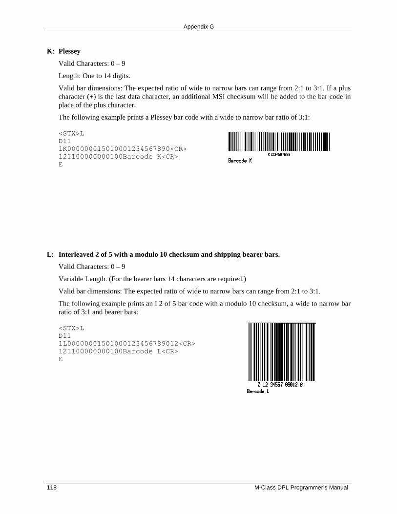
Appendix G
118 M-Class DPL Programmer’s Manual
K: Plessey
Valid Characters: 0 – 9
Length: One to 14 digits.
Valid bar dimensions: The expected ratio of wide to narrow bars can range from 2:1 to 3:1. If a pluscharacter (+) is the last data character, an additional MSI checksum will be added to the bar code inplace of the plus character.
The following example prints a Plessey bar code with a wide to narrow bar ratio of 3:1:
<STX>LD111K000000015010001234567890<CR>121100000000100Barcode K<CR>E
L: Interleaved 2 of 5 with a modulo 10 checksum and shipping bearer bars.
Valid Characters: 0 – 9
Variable Length. (For the bearer bars 14 characters are required.)
Valid bar dimensions: The expected ratio of wide to narrow bars can range from 2:1 to 3:1.
The following example prints an I 2 of 5 bar code with a modulo 10 checksum, a wide to narrow barratio of 3:1 and bearer bars:
<STX>LD111L00000001501000123456789012<CR>121100000000100Barcode L<CR>E
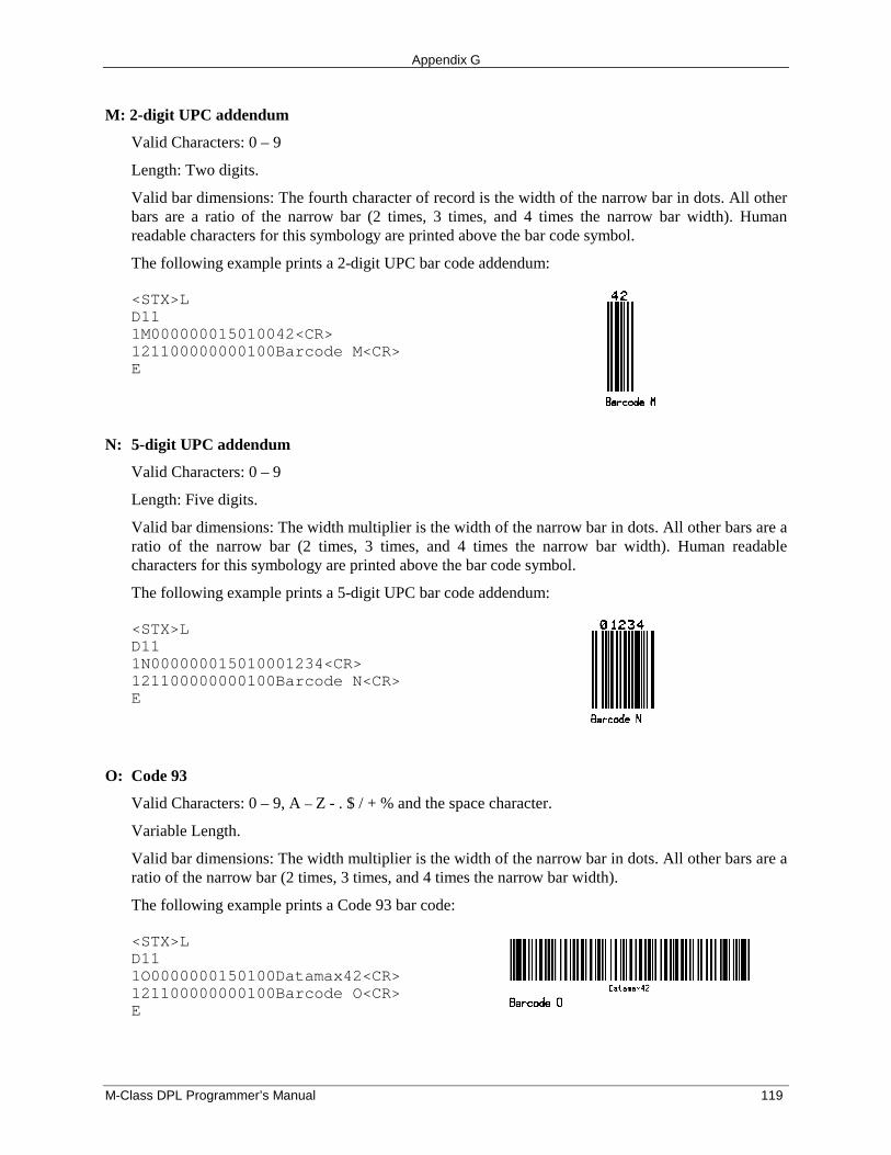
Appendix G
M-Class DPL Programmer’s Manual 119
M: 2-digit UPC addendum
Valid Characters: 0 – 9
Length: Two digits.
Valid bar dimensions: The fourth character of record is the width of the narrow bar in dots. All otherbars are a ratio of the narrow bar (2 times, 3 times, and 4 times the narrow bar width). Humanreadable characters for this symbology are printed above the bar code symbol.
The following example prints a 2-digit UPC bar code addendum:
<STX>LD111M000000015010042<CR>121100000000100Barcode M<CR>E
N: 5-digit UPC addendum
Valid Characters: 0 – 9
Length: Five digits.
Valid bar dimensions: The width multiplier is the width of the narrow bar in dots. All other bars are aratio of the narrow bar (2 times, 3 times, and 4 times the narrow bar width). Human readablecharacters for this symbology are printed above the bar code symbol.
The following example prints a 5-digit UPC bar code addendum:
<STX>LD111N000000015010001234<CR>121100000000100Barcode N<CR>E
O: Code 93
Valid Characters: 0 – 9, A – Z - . $ / + % and the space character.
Variable Length.
Valid bar dimensions: The width multiplier is the width of the narrow bar in dots. All other bars are aratio of the narrow bar (2 times, 3 times, and 4 times the narrow bar width).
The following example prints a Code 93 bar code:
<STX>LD111O0000000150100Datamax42<CR>121100000000100Barcode O<CR>E
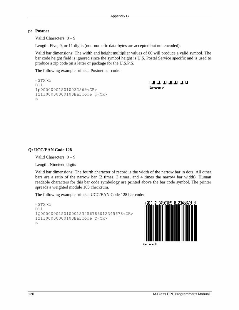
Appendix G
120 M-Class DPL Programmer’s Manual
p: Postnet
Valid Characters: 0 – 9
Length: Five, 9, or 11 digits (non-numeric data-bytes are accepted but not encoded).
Valid bar dimensions: The width and height multiplier values of 00 will produce a valid symbol. Thebar code height field is ignored since the symbol height is U.S. Postal Service specific and is used toproduce a zip code on a letter or package for the U.S.P.S.
The following example prints a Postnet bar code:
<STX>LD111p000000015010032569<CR>121100000000100Barcode p<CR>E
Q: UCC/EAN Code 128
Valid Characters: 0 – 9
Length: Nineteen digits
Valid bar dimensions: The fourth character of record is the width of the narrow bar in dots. All otherbars are a ratio of the narrow bar (2 times, 3 times, and 4 times the narrow bar width). Humanreadable characters for this bar code symbology are printed above the bar code symbol. The printerspreads a weighted module 103 checksum.
The following example prints a UCC/EAN Code 128 bar code:
<STX>LD111Q00000001501000123456789012345678<CR>121100000000100Barcode Q<CR>E
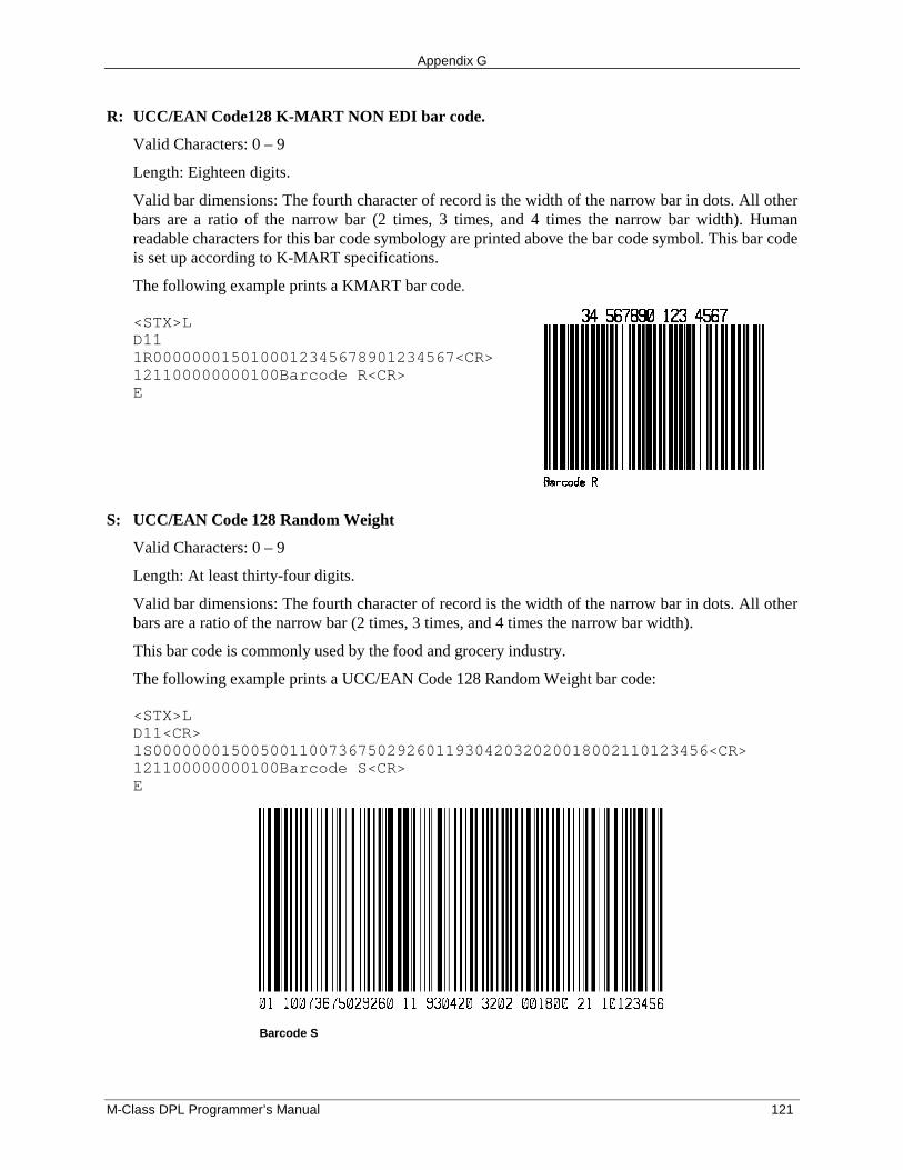
Appendix G
M-Class DPL Programmer’s Manual 121
R: UCC/EAN Code128 K-MART NON EDI bar code.
Valid Characters: 0 – 9
Length: Eighteen digits.
Valid bar dimensions: The fourth character of record is the width of the narrow bar in dots. All otherbars are a ratio of the narrow bar (2 times, 3 times, and 4 times the narrow bar width). Humanreadable characters for this bar code symbology are printed above the bar code symbol. This bar codeis set up according to K-MART specifications.
The following example prints a KMART bar code.
<STX>LD111R0000000150100012345678901234567<CR>121100000000100Barcode R<CR>E
S: UCC/EAN Code 128 Random Weight
Valid Characters: 0 – 9
Length: At least thirty-four digits.
Valid bar dimensions: The fourth character of record is the width of the narrow bar in dots. All otherbars are a ratio of the narrow bar (2 times, 3 times, and 4 times the narrow bar width).
This bar code is commonly used by the food and grocery industry.
The following example prints a UCC/EAN Code 128 Random Weight bar code:
<STX>LD11<CR>1S000000015005001100736750292601193042032020018002110123456<CR>121100000000100Barcode S<CR>E
Barcode S
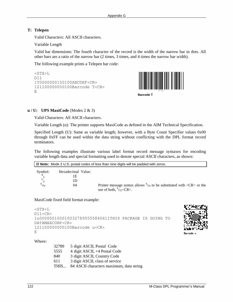
Appendix G
122 M-Class DPL Programmer’s Manual
T: Telepen
Valid Characters: All ASCII characters.
Variable Length
Valid bar dimensions: The fourth character of the record is the width of the narrow bar in dots. Allother bars are a ratio of the narrow bar (2 times, 3 times, and 4 times the narrow bar width).
The following example prints a Telepen bar code:
<STX>LD111T0000000150100ABCDEF<CR>121100000000100Barcode T<CR>E
Barcode T
u / U: UPS MaxiCode (Modes 2 & 3)
Valid Characters: All ASCII characters.
Variable Length (u): The printer supports MaxiCode as defined in the AIM Technical Specification.
Specified Length (U): Same as variable length; however, with a Byte Count Specifier values 0x00through 0xFF can be used within the data string without conflicting with the DPL format recordterminators.
The following examples illustrate various label format record message syntaxes for encodingvariable length data and special formatting used to denote special ASCII characters, as shown:
� Note: Mode 2 U.S. postal codes of less than nine digits will be padded with zeros.
Symbol: Hexadecimal Value:R
S 1EG
S 1DE
OT 04 Printer message syntax allows EOT to be substituted with <CR> or the
use of both, EOT<CR>.
MaxiCode fixed field format example:
<STX>LD11<CR>1u0000001000100327895555840611THIS PACKAGE IS GOING TODATAMAXCORP<CR>121100000000100Barcode u<CR>E
Where:32789 5 digit ASCII, Postal Code5555 4 digit ASCII, +4 Postal Code840 3 digit ASCII, Country Code611 3 digit ASCII, class of serviceTHIS... 84 ASCII characters maximum, data string
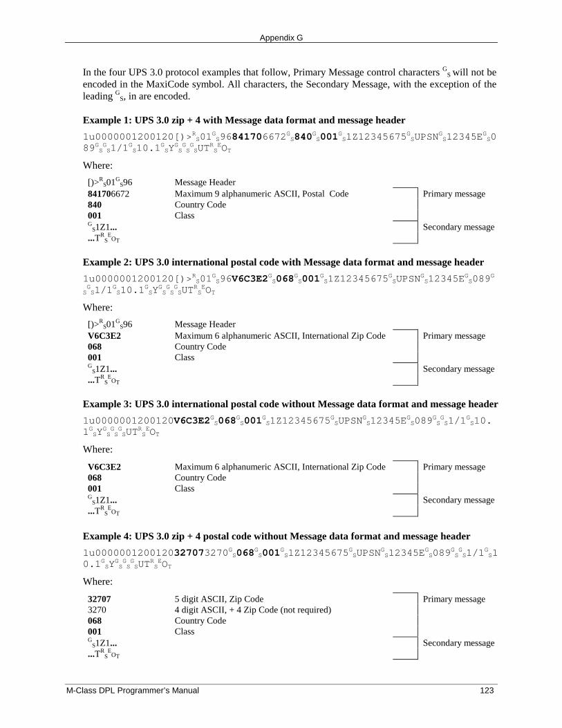
Appendix G
M-Class DPL Programmer’s Manual 123
In the four UPS 3.0 protocol examples that follow, Primary Message control characters GS will not be
encoded in the MaxiCode symbol. All characters, the Secondary Message, with the exception of theleading GS, in are encoded.
Example 1: UPS 3.0 zip + 4 with Message data format and message header
1u0000001200120[)>RS01GS96841706672
GS840
GS001
GS1Z12345675
GSUPSN
GS12345E
GS0
89GSGS1/1
GS10.1
GSY
GSGSGSUT
RSEOT
Where:
[)>RS01G
S96 Message Header841706672 Maximum 9 alphanumeric ASCII, Postal Code Primary message840 Country Code001 ClassG
S1Z1... Secondary message...TR
SE
OT
Example 2: UPS 3.0 international postal code with Message data format and message header
1u0000001200120[)>RS01GS96V6C3E2
GS068
GS001
GS1Z12345675
GSUPSN
GS12345E
GS089
G
SGS1/1
GS10.1
GSY
GSGSGSUT
RSEOT
Where:
[)>RS01G
S96 Message HeaderV6C3E2 Maximum 6 alphanumeric ASCII, International Zip Code Primary message068 Country Code001 ClassG
S1Z1... Secondary message...TR
SE
OT
Example 3: UPS 3.0 international postal code without Message data format and message header
1u0000001200120V6C3E2GS068GS001
GS1Z12345675
GSUPSN
GS12345E
GS089
GSGS1/1
GS10.
1GSYGSGSGSUT
RSEOT
Where:
V6C3E2 Maximum 6 alphanumeric ASCII, International Zip Code Primary message068 Country Code001 ClassG
S1Z1... Secondary message...TR
SE
OT
Example 4: UPS 3.0 zip + 4 postal code without Message data format and message header
1u0000001200120327073270GS068GS001
GS1Z12345675
GSUPSN
GS12345E
GS089
GSGS1/1
GS1
0.1GSYGSGSGSUT
RSEOT
Where:
32707 5 digit ASCII, Zip Code Primary message3270 4 digit ASCII, + 4 Zip Code (not required)068 Country Code001 ClassG
S1Z1... Secondary message...TR
SE
OT
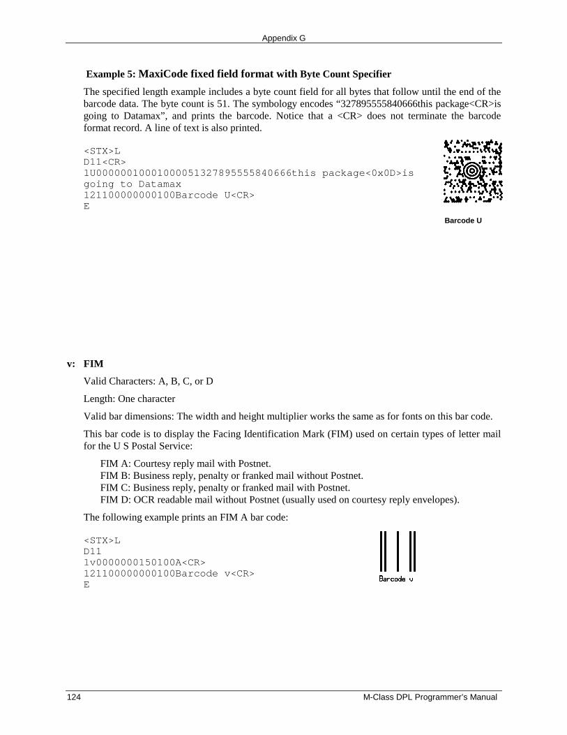
Appendix G
124 M-Class DPL Programmer’s Manual
Example 5: MaxiCode fixed field format with Byte Count Specifier
The specified length example includes a byte count field for all bytes that follow until the end of thebarcode data. The byte count is 51. The symbology encodes “327895555840666this package<CR>isgoing to Datamax”, and prints the barcode. Notice that a <CR> does not terminate the barcodeformat record. A line of text is also printed.
<STX>LD11<CR>1U00000010001000051327895555840666this package<0x0D>isgoing to Datamax121100000000100Barcode U<CR>E
Barcode U
v: FIM
Valid Characters: A, B, C, or D
Length: One character
Valid bar dimensions: The width and height multiplier works the same as for fonts on this bar code.
This bar code is to display the Facing Identification Mark (FIM) used on certain types of letter mailfor the U S Postal Service:
FIM A: Courtesy reply mail with Postnet.FIM B: Business reply, penalty or franked mail without Postnet.FIM C: Business reply, penalty or franked mail with Postnet.FIM D: OCR readable mail without Postnet (usually used on courtesy reply envelopes).
The following example prints an FIM A bar code:
<STX>LD111v0000000150100A<CR>121100000000100Barcode v<CR>E
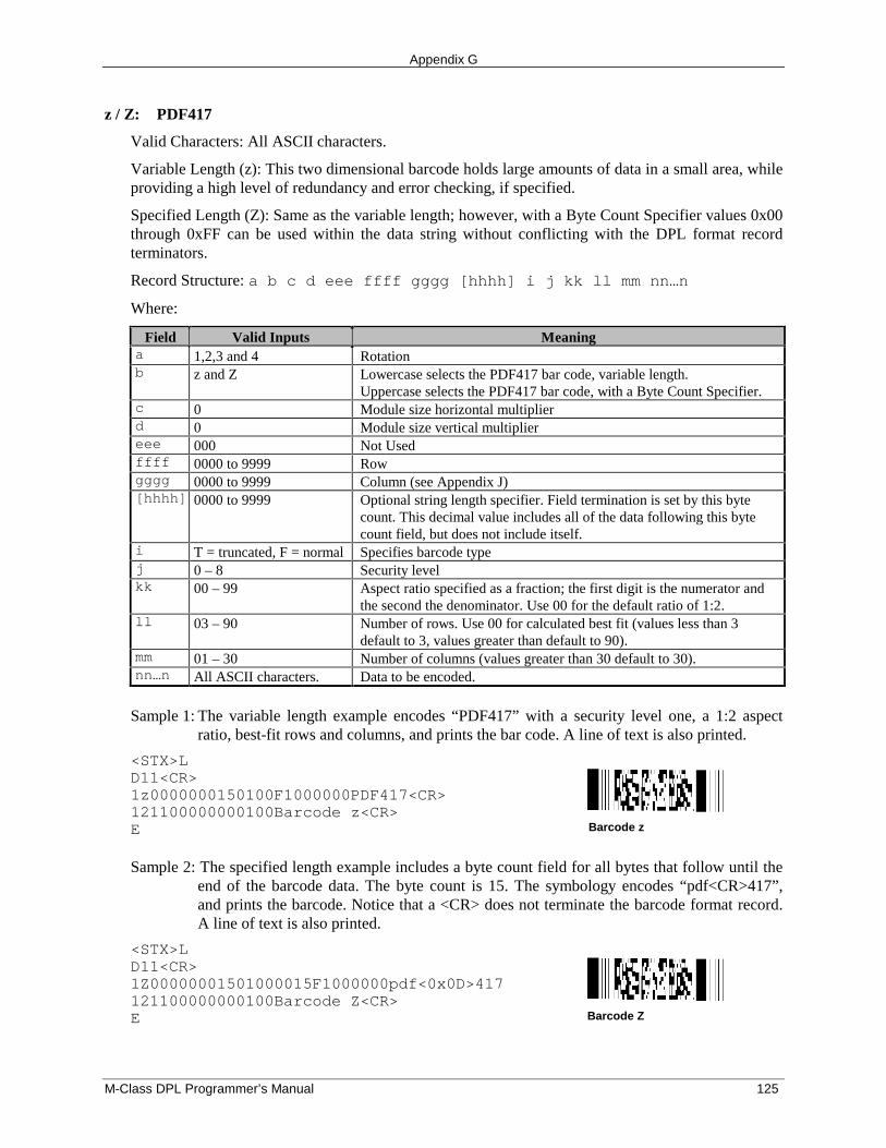
Appendix G
M-Class DPL Programmer’s Manual 125
z / Z: PDF417
Valid Characters: All ASCII characters.
Variable Length (z): This two dimensional barcode holds large amounts of data in a small area, whileproviding a high level of redundancy and error checking, if specified.
Specified Length (Z): Same as the variable length; however, with a Byte Count Specifier values 0x00through 0xFF can be used within the data string without conflicting with the DPL format recordterminators.
Record Structure: a b c d eee ffff gggg [hhhh] i j kk ll mm nn…n
Where:
Field Valid Inputs Meaninga 1,2,3 and 4 Rotationb z and Z Lowercase selects the PDF417 bar code, variable length.
Uppercase selects the PDF417 bar code, with a Byte Count Specifier.c 0 Module size horizontal multiplierd 0 Module size vertical multipliereee 000 Not Usedffff 0000 to 9999 Rowgggg 0000 to 9999 Column (see Appendix J)[hhhh] 0000 to 9999 Optional string length specifier. Field termination is set by this byte
count. This decimal value includes all of the data following this bytecount field, but does not include itself.
i T = truncated, F = normal Specifies barcode typej 0 – 8 Security levelkk 00 – 99 Aspect ratio specified as a fraction; the first digit is the numerator and
the second the denominator. Use 00 for the default ratio of 1:2.ll 03 – 90 Number of rows. Use 00 for calculated best fit (values less than 3
default to 3, values greater than default to 90).mm 01 – 30 Number of columns (values greater than 30 default to 30).nn…n All ASCII characters. Data to be encoded.
Sample 1: The variable length example encodes “PDF417” with a security level one, a 1:2 aspectratio, best-fit rows and columns, and prints the bar code. A line of text is also printed.
<STX>LD11<CR>1z0000000150100F1000000PDF417<CR>121100000000100Barcode z<CR>E Barcode z
Sample 2: The specified length example includes a byte count field for all bytes that follow until theend of the barcode data. The byte count is 15. The symbology encodes “pdf<CR>417”,and prints the barcode. Notice that a <CR> does not terminate the barcode format record.A line of text is also printed.
<STX>LD11<CR>1Z00000001501000015F1000000pdf<0x0D>417121100000000100Barcode Z<CR>E Barcode Z
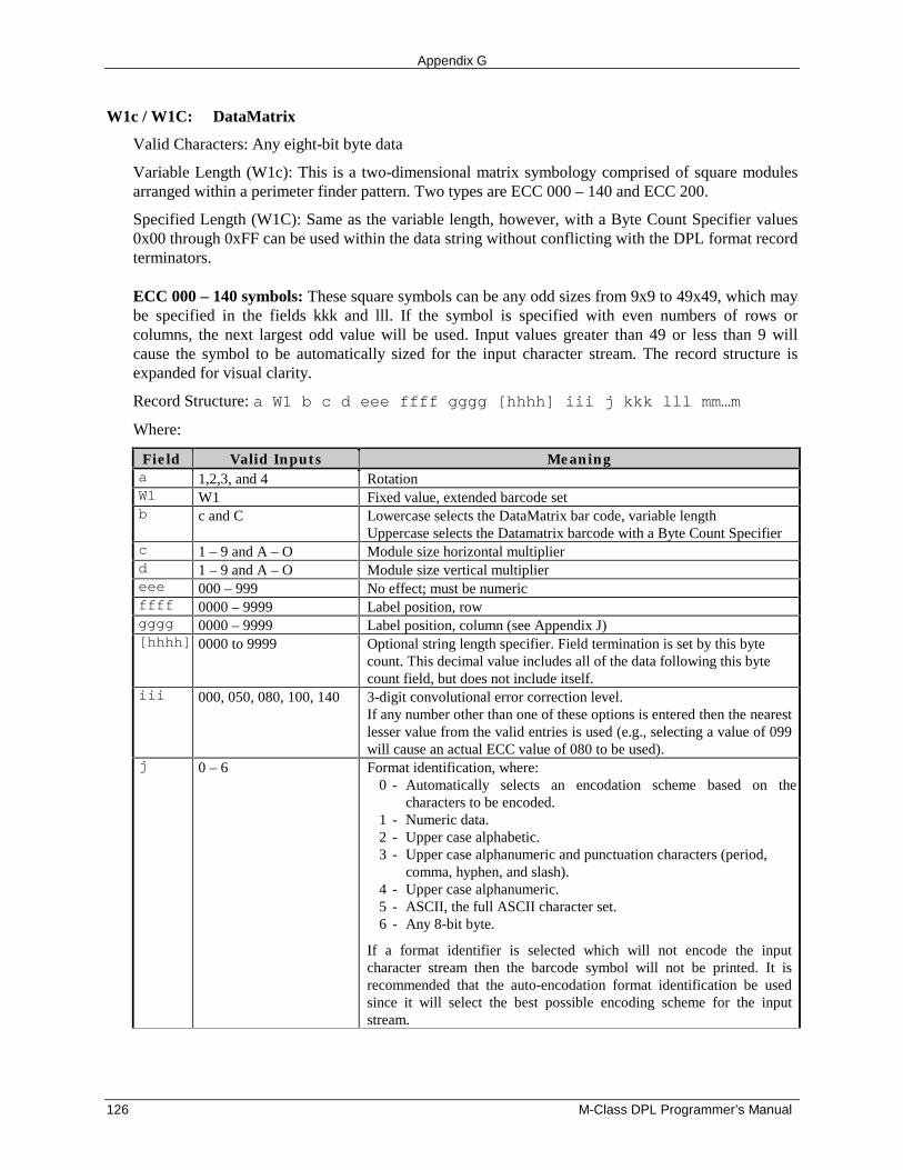
Appendix G
126 M-Class DPL Programmer’s Manual
W1c / W1C: DataMatrix
Valid Characters: Any eight-bit byte data
Variable Length (W1c): This is a two-dimensional matrix symbology comprised of square modulesarranged within a perimeter finder pattern. Two types are ECC 000 – 140 and ECC 200.
Specified Length (W1C): Same as the variable length, however, with a Byte Count Specifier values0x00 through 0xFF can be used within the data string without conflicting with the DPL format recordterminators.
ECC 000 – 140 symbols: These square symbols can be any odd sizes from 9x9 to 49x49, which maybe specified in the fields kkk and lll. If the symbol is specified with even numbers of rows orcolumns, the next largest odd value will be used. Input values greater than 49 or less than 9 willcause the symbol to be automatically sized for the input character stream. The record structure isexpanded for visual clarity.
Record Structure: a W1 b c d eee ffff gggg [hhhh] iii j kkk lll mm…m
Where:
Field Valid Inputs Meaninga 1,2,3, and 4 RotationW1 W1 Fixed value, extended barcode setb c and C Lowercase selects the DataMatrix bar code, variable length
Uppercase selects the Datamatrix barcode with a Byte Count Specifierc 1 – 9 and A – O Module size horizontal multiplierd 1 – 9 and A – O Module size vertical multipliereee 000 – 999 No effect; must be numericffff 0000 – 9999 Label position, rowgggg 0000 – 9999 Label position, column (see Appendix J)[hhhh] 0000 to 9999 Optional string length specifier. Field termination is set by this byte
count. This decimal value includes all of the data following this bytecount field, but does not include itself.
iii 000, 050, 080, 100, 140 3-digit convolutional error correction level.If any number other than one of these options is entered then the nearestlesser value from the valid entries is used (e.g., selecting a value of 099will cause an actual ECC value of 080 to be used).
j 0 – 6 Format identification, where:0 - Automatically selects an encodation scheme based on the
characters to be encoded.1 - Numeric data.2 - Upper case alphabetic.3 - Upper case alphanumeric and punctuation characters (period,
comma, hyphen, and slash).4 - Upper case alphanumeric.5 - ASCII, the full ASCII character set.6 - Any 8-bit byte.
If a format identifier is selected which will not encode the inputcharacter stream then the barcode symbol will not be printed. It isrecommended that the auto-encodation format identification be usedsince it will select the best possible encoding scheme for the inputstream.
Appendix G
M-Class DPL Programmer’s Manual 127
Field Valid Inputs Meaningkkk 9,11,13…49.
ECC 140 minimum is 15.A 3 digit odd number (or 000) of rows requested. 000 causes rows to beautomatically determined. If the rows and columns do not match, thesymbol will be sized to a square using the greater of the two values.
lll 9,11,13…49.ECC 140 minimum is 15.
A 3 digit odd number (or 000) of columns requested. 000 causescolumns to be automatically determined. If the rows and columns donot match, the symbol will be sized to a square using the greater of thetwo values.
mm…m 8-bit data, followed by atermination character.
Data to be encoded.
ECC 200 symbols: There are 24 square symbol sizes available, which may be specified in fields kkkand lll, measured in modules as indicated below. If an ECC 200 symbol is specified with oddnumbers of rows or columns, the next largest even value will be used. Input values greater than 144or less than 10 will cause the symbol to be automatically sized for the input character stream. Therecord structure is expanded for visual clarity.
Record Structure: a W1 b c d eee ffff gggg [hhhh] iii j kkk lll mm…m
Where:
Field Valid Inputs Meaninga 1,2,3, and 4 RotationW1 W1 Fixed value, extended barcode setb c and C Lowercase selects the DataMatrix bar code, variable length
Uppercase selects the Datamatrix barcode with a Byte Count Specifierc 1 to 9 and A to O Module size horizontal multiplierd 1 to 9 and A to O Module size vertical multipliereee 000 to 999 No Effect; Must be numericffff 0000 to 9999 Label position, rowgggg 0000 to 9999 Label position, column (see Appendix J)[hhhh] 0000 to 9999 Optional string length specifier. Field termination is set by this byte
count. This decimal value includes all of the data following this bytecount field, but does not include itself.
iii 200 Reed-Solomon error correction.j 0 Fixed value, not usedkkk 10, 12, 14, 16, 18, 20, 22,
24, 26, 32, 36, 40, 44, 48,52, 64, 72, 80, 88, 96,104, 120, 132, 144
A 3 digit even number (or 000) of rows requested. 000 causes rows tobe automatically determined. If the rows and columns do not match, thesymbol will be sized to a square using the greater of the two values.
lll 10, 12, 14, 16, 18, 20, 22,24, 26, 32, 36, 40, 44, 48,52, 64, 72, 80, 88, 96,104, 120, 132, 144
A 3 digit even number (or 000) of columns requested. 000 causescolumns to be automatically determined. If the rows and columns donot match, the symbol will be sized to a square using the greater of thetwo values.
mm…m 8-bit data, followed by atermination character.
Data to be encoded.
Sample 1: The variable length example encodes “DATAMAX” using a module multiplier of 4, withan error correction level of 80, automatic encodation and determination of rows andcolumns, and then a prints the bar code. A line of text is also printed.
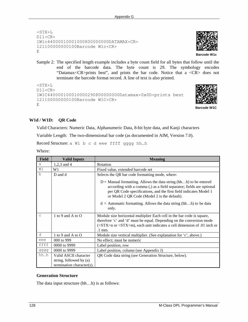
Appendix G
128 M-Class DPL Programmer’s Manual
<STX>LD11<CR>1W1c44000010001000800000000DATAMAX<CR>121100000000100Barcode W1c<CR>E
Barcode W1c
Sample 2: The specified length example includes a byte count field for all bytes that follow until theend of the barcode data. The byte count is 29. The symbology encodes“Datamax<CR>prints best”, and prints the bar code. Notice that a <CR> does notterminate the barcode format record. A line of text is also printed.
<STX>LD11<CR>1W1C440000100010000290800000000Datamax<0x0D>prints best121100000000100Barcode W1C<CR>E
Barcode W1C
W1d / W1D: QR Code
Valid Characters: Numeric Data, Alphanumeric Data, 8-bit byte data, and Kanji characters
Variable Length: The two-dimensional bar code (as documented in AIM, Version 7.0).
Record Structure: a W1 b c d eee ffff gggg hh…h
Where:
Field Valid Inputs Meaninga 1,2,3 and 4 RotationW1 W1 Fixed value, extended barcode setb D and d Selects the QR bar code formatting mode, where:
D = Manual formatting. Allows the data string (hh…h) to be entered according with a comma (,) as a field separator; fields are optional per QR Code specifications, and the first field indicates Model 1 or Model 2 QR Code (Model 2 is the default).
d = Automatic formatting. Allows the data string (hh…h) to be data only.
c 1 to 9 and A to O Module size horizontal multiplier Each cell in the bar code is square,therefore ‘c’ and ‘d’ must be equal. Depending on the conversion mode(<STX>n or <STX>m), each unit indicates a cell dimension of .01 inch or.1 mm.
d 1 to 9 and A to O Module size vertical multiplier. (See explanation for ‘c’, above.)eee 000 to 999 No effect; must be numericffff 0000 to 9999 Label position, rowgggg 0000 to 9999 Label position, column (see Appendix J)hh…h Valid ASCII character
string, followed by (a)termination character(s).
QR Code data string (see Generation Structure, below).
Generation Structure
The data input structure (hh…h) is as follows:
Appendix G
M-Class DPL Programmer’s Manual 129
Auto Format (bar code W1d)
With barcode identifier ‘d’, the data begins after the last character of the column position field,and does not include any command characters. The data string is terminated with a terminationcharacter, usually a 0x0d hex that occurs twice in succession. The bar code symbol will have thefollowing characteristics:
1. Model 22. Error Correction Code Level = ‘M’ (Standard Reliability Level)3. Mask Selection = Automatic4. Data Input Mode = Automatic
Example:
<STX>LD11<CR>1W1d4400000100010This is the data portion<CR><CR>121100000000100Barcode W1D<CR>E
(Twoterminationcharactersrequired.)
Manual Formatting (bar code W1D)
With barcode identifier ‘D’, minor changes allow flexibility for data entry. (Spaces have beenadded for readability.)
[q,] e [m] i, cdata cdata cdata…cdata term
Where:
Field Valid Inputs Meaningq 1, 2 QR Code Model number, optional. Model 2 is the default.e H, Q, M, L Error Correction Level:
H = Ultra Reliability LevelQ = High Reliability LevelM = Standard Reliability LevelL = High Density Level
m 0 – 8, none Mask Number, optional:None = Automatic Selection0-7 = Mask 0 to Mask 78 = No Mask
i A, a, M, m Data Input Mode:A = Automatic setting, ASCIIa = Automatic, hex-ASCIIM = Manual Setting, ASCIIm = manual, hex-ASCII
cdata N, A, B, Kimmediatelyfollowed by data
Character Mode:N = Numeric, N dataA = Alphanumeric, A dataB = Binary , Bnnnn data (where nnnn = data byte-count, 4
decimal digits; byte-count /2 for hex-ASCIIK = Kanji, K data
term <CR>, <CR><CR> The data string is terminated with a termination character, generally a0x0d hex, but can be changed by the operator. If the Data Input Modeis Automatic, the data string is terminated with two successivetermination characters.
Appendix G
130 M-Class DPL Programmer’s Manual
If HEX/ASCII mode is selected in manual Data Input Mode, only the data for Kanji or Binarydata types will be converted, therefore the other data types and all command characters must beentered in ASCII format. If HEX/ASCII is selected in automatic Data Input Mode, all of the datamust be entered in HEX/ASCII format.
Data Append Mode String Format, Manual Formatting - barcode W1D
D aa tt pp I
Where:
Field Valid Inputs MeaningD D Data Append Mode String Format indicatoraa 00, 99 QR Code Number in Append Series, 2 decimal digitstt Total number of QR Codes in series, 2 decimal digitspp Value of Parity, 2 digits, 8 LSBs of data paritye H, Q, M, L As abovem 0 – 8, none As abovei A, a, M, m As abovecdata N, A, B, K
immediately followed by dataAs above
term <CR>, <CR><CR> As above
Characteristics
Models:
Model 1 (original version), bar code versions 1 through 14A. ECC Levels ‘H’, ‘M’, ‘Q’, and ‘L’B. Mask Selection Automatic or 0 through 8C. Data Input Modes Automatic and ManualD. Data Append Mode
Model 2 (enhanced version), bar code versions 1 through 40A. ECC Levels ‘H’, ‘M’, ‘Q’, and ‘L’B. Mask Selection Automatic or 0 through 8C. Data Input Modes Automatic and ManualD. Data Append Mode
Representation of data:
Dark Cell = Binary 1Light Cell = Binary 0
Symbol Size (not including quiet zone, 4 cells on each of the 4 sides):
Model 1: 21 X 21 cells to 73 X 73 cells (Versions 1 to 14, increase in steps of 4 cells per side)Model 2: 21 X 21 cells to 177 X 177 cells (Versions 1 to 40, increase in steps of 4 cells per side)
Data Characters per symbol (maximum for symbol size):
Numeric DataModel 1; Version 14; ECC = L: 1,167 charactersModel 2; Version 40; ECC = L: 7,089 characters
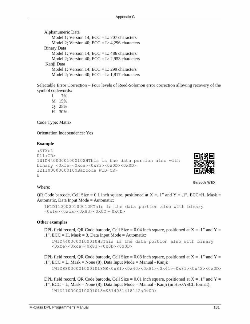
Appendix G
M-Class DPL Programmer’s Manual 131
Alphanumeric DataModel 1; Version 14; ECC = L: 707 charactersModel 2; Version 40; ECC = L: 4,296 characters
Binary DataModel 1; Version 14; ECC = L: 486 charactersModel 2; Version 40; ECC = L: 2,953 characters
Kanji DataModel 1; Version 14; ECC = L: 299 charactersModel 2; Version 40; ECC = L: 1,817 characters
Selectable Error Correction – Four levels of Reed-Solomon error correction allowing recovery of thesymbol codewords:
L 7%M 15%Q 25%H 30%
Code Type: Matrix
Orientation Independence: Yes
Example
<STX>LD11<CR>1W1D44000001000102HThis is the data portion also withbinary <0xfe><0xca><0x83><0x0D><0x0D>121100000000100Barcode W1D<CR>E
Barcode W1D
Where:
QR Code barcode, Cell Size = 0.1 inch square, positioned at X =. 1” and Y = .1”, ECC=H, Mask =Automatic, Data Input Mode = Automatic:
1W1D1100000100010HThis is the data portion also with binary<0xfe><0xca><0x83><0x0D><0x0D>
Other examples
DPL field record, QR Code barcode, Cell Size = 0.04 inch square, positioned at X = .1” and Y =.1”, ECC = H, Mask = 3, Data Input Mode = Automatic:
1W1D4400000100010H3This is the data portion also with binary<0xfe><0xca><0x83><0x0D><0x0D>
DPL field record, QR Code barcode, Cell Size = 0.08 inch square, positioned at X = .1” and Y =.1”, ECC = L, Mask = None (8), Data Input Mode = Manual - Kanji:
1W1D8800000100010L8MK<0x81><0x40><0x81><0x41><0x81><0x42><0x0D>
DPL field record, QR Code barcode, Cell Size = 0.01 inch square, positioned at X = .1” and Y =.1”, ECC = L, Mask = None (8), Data Input Mode = Manual - Kanji (in Hex/ASCII format):
1W1D1100000100010L8mK814081418142<0x0D>
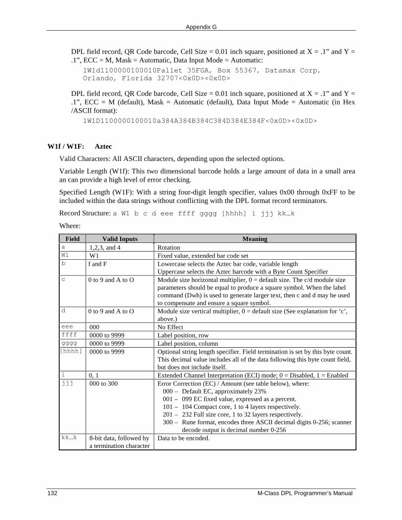
Appendix G
132 M-Class DPL Programmer’s Manual
DPL field record, QR Code barcode, Cell Size = 0.01 inch square, positioned at X = .1” and Y =.1”, ECC = M, Mask = Automatic, Data Input Mode = Automatic:
1W1d1100000100010Pallet 35FGA, Box 55367, Datamax Corp,Orlando, Florida 32707<0x0D><0x0D>
DPL field record, QR Code barcode, Cell Size = 0.01 inch square, positioned at X = .1” and Y =.1”, ECC = M (default), Mask = Automatic (default), Data Input Mode = Automatic (in Hex/ASCII format):
1W1D1100000100010a384A384B384C384D384E384F<0x0D><0x0D>
W1f / W1F: Aztec
Valid Characters: All ASCII characters, depending upon the selected options.
Variable Length (W1f): This two dimensional barcode holds a large amount of data in a small areaan can provide a high level of error checking.
Specified Length (W1F): With a string four-digit length specifier, values 0x00 through 0xFF to beincluded within the data strings without conflicting with the DPL format record terminators.
Record Structure: a W1 b c d eee ffff gggg [hhhh] i jjj kk…k
Where:
Field Valid Inputs Meaninga 1,2,3, and 4 RotationW1 W1 Fixed value, extended bar code setb f and F Lowercase selects the Aztec bar code, variable length
Uppercase selects the Aztec barcode with a Byte Count Specifierc 0 to 9 and A to O Module size horizontal multiplier, 0 = default size. The c/d module size
parameters should be equal to produce a square symbol. When the labelcommand (Dwh) is used to generate larger text, then c and d may be usedto compensate and ensure a square symbol.
d 0 to 9 and A to O Module size vertical multiplier, 0 = default size (See explanation for ‘c’,above.)
eee 000 No Effectffff 0000 to 9999 Label position, rowgggg 0000 to 9999 Label position, column[hhhh] 0000 to 9999 Optional string length specifier. Field termination is set by this byte count.
This decimal value includes all of the data following this byte count field,but does not include itself.
i 0, 1 Extended Channel Interpretation (ECI) mode; 0 = Disabled, 1 = Enabledjjj 000 to 300 Error Correction (EC) / Amount (see table below), where:
000 – Default EC, approximately 23%001 – 099 EC fixed value, expressed as a percent.101 – 104 Compact core, 1 to 4 layers respectively.201 – 232 Full size core, 1 to 32 layers respectively.300 – Rune format, encodes three ASCII decimal digits 0-256; scanner
decode output is decimal number 0-256kk…k 8-bit data, followed by
a termination characterData to be encoded.
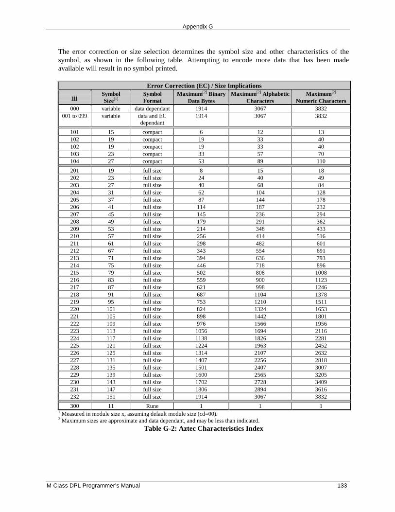
Appendix G
M-Class DPL Programmer’s Manual 133
The error correction or size selection determines the symbol size and other characteristics of thesymbol, as shown in the following table. Attempting to encode more data that has been madeavailable will result in no symbol printed.
Error Correction (EC) / Size Implications
jjjSymbolSize[1]
SymbolFormat
Maximum[2] BinaryData Bytes
Maximum[2] AlphabeticCharacters
Maximum[2]
Numeric Characters000 variable data dependant 1914 3067 3832
001 to 099 variable data and ECdependant
1914 3067 3832
101 15 compact 6 12 13102 19 compact 19 33 40102 19 compact 19 33 40103 23 compact 33 57 70104 27 compact 53 89 110
201 19 full size 8 15 18202 23 full size 24 40 49203 27 full size 40 68 84204 31 full size 62 104 128205 37 full size 87 144 178206 41 full size 114 187 232207 45 full size 145 236 294208 49 full size 179 291 362209 53 full size 214 348 433210 57 full size 256 414 516211 61 full size 298 482 601212 67 full size 343 554 691213 71 full size 394 636 793214 75 full size 446 718 896215 79 full size 502 808 1008216 83 full size 559 900 1123217 87 full size 621 998 1246218 91 full size 687 1104 1378219 95 full size 753 1210 1511220 101 full size 824 1324 1653221 105 full size 898 1442 1801222 109 full size 976 1566 1956223 113 full size 1056 1694 2116224 117 full size 1138 1826 2281225 121 full size 1224 1963 2452226 125 full size 1314 2107 2632227 131 full size 1407 2256 2818228 135 full size 1501 2407 3007229 139 full size 1600 2565 3205230 143 full size 1702 2728 3409231 147 full size 1806 2894 3616232 151 full size 1914 3067 3832
300 11 Rune 1 1 11 Measured in module size x, assuming default module size (cd=00).2 Maximum sizes are approximate and data dependant, and may be less than indicated.
Table G-2: Aztec Characteristics Index
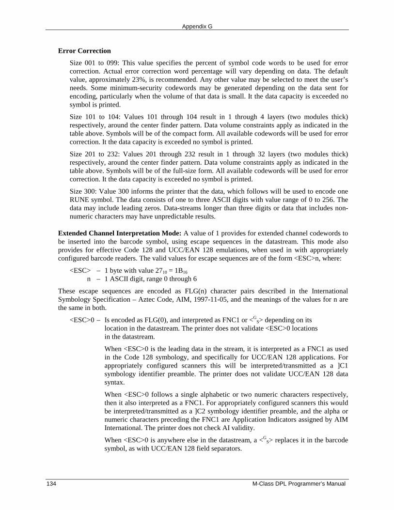
Appendix G
134 M-Class DPL Programmer’s Manual
Error Correction
Size 001 to 099: This value specifies the percent of symbol code words to be used for errorcorrection. Actual error correction word percentage will vary depending on data. The defaultvalue, approximately 23%, is recommended. Any other value may be selected to meet the user’sneeds. Some minimum-security codewords may be generated depending on the data sent forencoding, particularly when the volume of that data is small. It the data capacity is exceeded nosymbol is printed.
Size 101 to 104: Values 101 through 104 result in 1 through 4 layers (two modules thick)respectively, around the center finder pattern. Data volume constraints apply as indicated in thetable above. Symbols will be of the compact form. All available codewords will be used for errorcorrection. It the data capacity is exceeded no symbol is printed.
Size 201 to 232: Values 201 through 232 result in 1 through 32 layers (two modules thick)respectively, around the center finder pattern. Data volume constraints apply as indicated in thetable above. Symbols will be of the full-size form. All available codewords will be used for errorcorrection. It the data capacity is exceeded no symbol is printed.
Size 300: Value 300 informs the printer that the data, which follows will be used to encode oneRUNE symbol. The data consists of one to three ASCII digits with value range of 0 to 256. Thedata may include leading zeros. Data-streams longer than three digits or data that includes non-numeric characters may have unpredictable results.
Extended Channel Interpretation Mode: A value of 1 provides for extended channel codewords tobe inserted into the barcode symbol, using escape sequences in the datastream. This mode alsoprovides for effective Code 128 and UCC/EAN 128 emulations, when used in with appropriatelyconfigured barcode readers. The valid values for escape sequences are of the form <ESC>n, where:
<ESC> – 1 byte with value 2710 = 1B16
n – 1 ASCII digit, range 0 through 6
These escape sequences are encoded as FLG(n) character pairs described in the InternationalSymbology Specification – Aztec Code, AIM, 1997-11-05, and the meanings of the values for n arethe same in both.
<ESC>0 – Is encoded as FLG(0), and interpreted as FNC1 or <GS> depending on its
location in the datastream. The printer does not validate <ESC>0 locations in the datastream.
When <ESC>0 is the leading data in the stream, it is interpreted as a FNC1 as usedin the Code 128 symbology, and specifically for UCC/EAN 128 applications. Forappropriately configured scanners this will be interpreted/transmitted as a ]C1symbology identifier preamble. The printer does not validate UCC/EAN 128 datasyntax.
When <ESC>0 follows a single alphabetic or two numeric characters respectively,then it also interpreted as a FNC1. For appropriately configured scanners this wouldbe interpreted/transmitted as a ]C2 symbology identifier preamble, and the alpha ornumeric characters preceding the FNC1 are Application Indicators assigned by AIMInternational. The printer does not check AI validity.
When <ESC>0 is anywhere else in the datastream, a <GS> replaces it in the barcode
symbol, as with UCC/EAN 128 field separators.
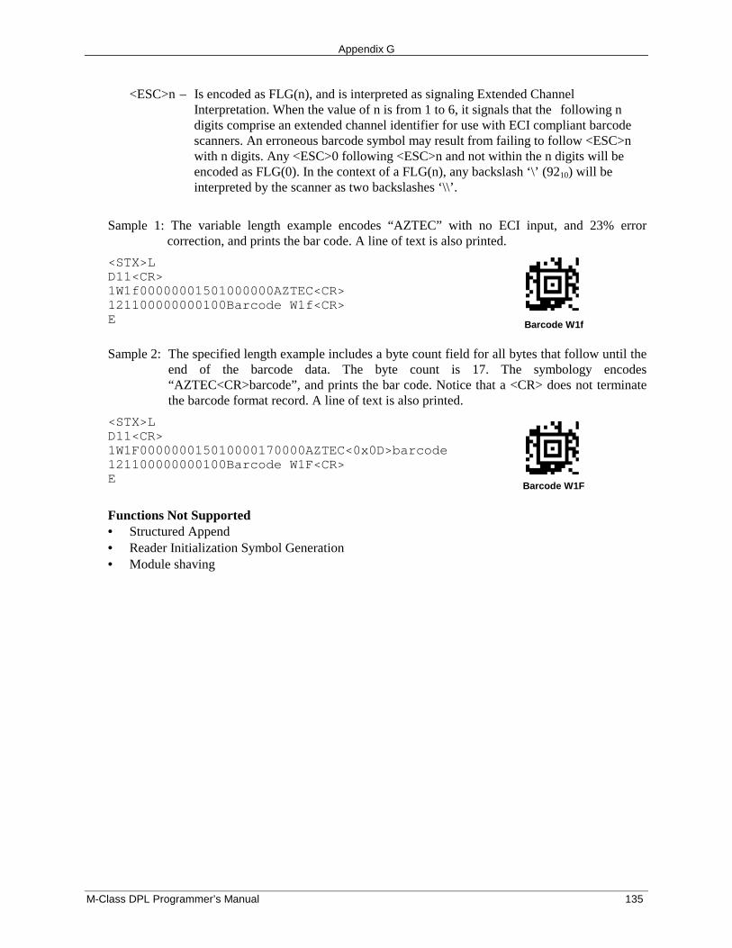
Appendix G
M-Class DPL Programmer’s Manual 135
<ESC>n – Is encoded as FLG(n), and is interpreted as signaling Extended Channel Interpretation. When the value of n is from 1 to 6, it signals that the following n digits comprise an extended channel identifier for use with ECI compliant barcode scanners. An erroneous barcode symbol may result from failing to follow <ESC>n with n digits. Any <ESC>0 following <ESC>n and not within the n digits will be encoded as FLG(0). In the context of a FLG(n), any backslash ‘\’ (9210) will be interpreted by the scanner as two backslashes ‘\\’.
Sample 1: The variable length example encodes “AZTEC” with no ECI input, and 23% errorcorrection, and prints the bar code. A line of text is also printed.
<STX>LD11<CR>1W1f00000001501000000AZTEC<CR>121100000000100Barcode W1f<CR>E Barcode W1f
Sample 2: The specified length example includes a byte count field for all bytes that follow until theend of the barcode data. The byte count is 17. The symbology encodes“AZTEC<CR>barcode”, and prints the bar code. Notice that a <CR> does not terminatethe barcode format record. A line of text is also printed.
<STX>LD11<CR>1W1F000000015010000170000AZTEC<0x0D>barcode121100000000100Barcode W1F<CR>E
Barcode W1F
Functions Not Supported• Structured Append• Reader Initialization Symbol Generation• Module shaving
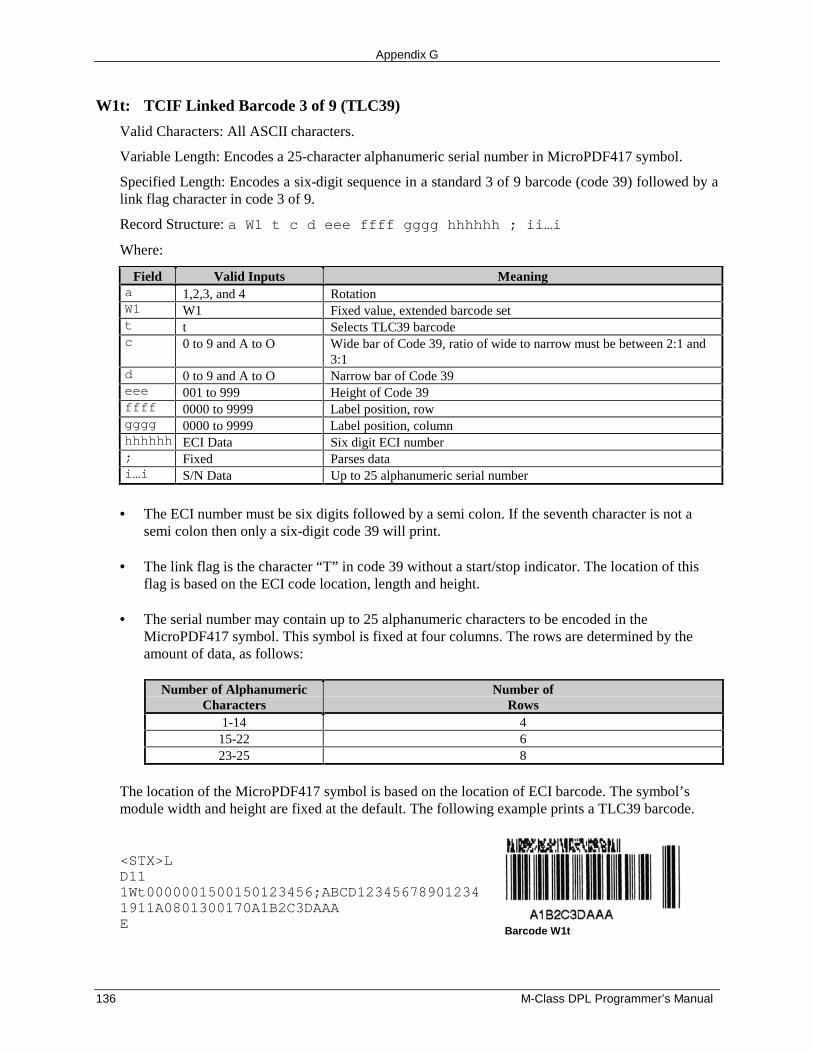
Appendix G
136 M-Class DPL Programmer’s Manual
W1t: TCIF Linked Barcode 3 of 9 (TLC39)
Valid Characters: All ASCII characters.
Variable Length: Encodes a 25-character alphanumeric serial number in MicroPDF417 symbol.
Specified Length: Encodes a six-digit sequence in a standard 3 of 9 barcode (code 39) followed by alink flag character in code 3 of 9.
Record Structure: a W1 t c d eee ffff gggg hhhhhh ; ii…i
Where:
Field Valid Inputs Meaninga 1,2,3, and 4 RotationW1 W1 Fixed value, extended barcode sett t Selects TLC39 barcodec 0 to 9 and A to O Wide bar of Code 39, ratio of wide to narrow must be between 2:1 and
3:1d 0 to 9 and A to O Narrow bar of Code 39eee 001 to 999 Height of Code 39ffff 0000 to 9999 Label position, rowgggg 0000 to 9999 Label position, columnhhhhhh ECI Data Six digit ECI number; Fixed Parses datai…i S/N Data Up to 25 alphanumeric serial number
• The ECI number must be six digits followed by a semi colon. If the seventh character is not asemi colon then only a six-digit code 39 will print.
• The link flag is the character “T” in code 39 without a start/stop indicator. The location of thisflag is based on the ECI code location, length and height.
• The serial number may contain up to 25 alphanumeric characters to be encoded in theMicroPDF417 symbol. This symbol is fixed at four columns. The rows are determined by theamount of data, as follows:
Number of AlphanumericCharacters
Number ofRows
1-14 415-22 623-25 8
The location of the MicroPDF417 symbol is based on the location of ECI barcode. The symbol’smodule width and height are fixed at the default. The following example prints a TLC39 barcode.
<STX>LD111Wt0000001500150123456;ABCD123456789012341911A0801300170A1B2C3DAAAE
Barcode W1t
Appendix G
M-Class DPL Programmer’s Manual 137
W1z / W1Z: MicroPDF417
Valid Characters: All ASCII characters, depending on the selected options.
Variable Length: This is a 2 dimensional barcode capable of holding large amounts of data in a smallarea. It provides a high level of redundancy and error checking.
Specified Length: With a string four-digit length specifier, values 0x00 through 0xFF to be includedwithin the data strings without conflicting with the DPL format record terminators.
Record Structure: a W1 b c d eee ffff gggg [hhhh] i j k l 0 mm…m
Where:
Field Valid Inputs Meaninga 1,2,3, and 4 RotationW1 W1 Fixed value, extended barcode setb z and Z Lowercase selects the MicroPDF417 bar code, variable length
Uppercase selects the MicroPDF417 barcode with a Byte CountSpecifier.
c 0 to 9 and A to O Module size horizontal multiplier; 0 = default size.d 0 to 9 and A to O Module size vertical multiplier; 0 = default size.eee 000 No Effectffff 0000 to 9999 Label position, rowgggg 0000 to 9999 Label position, column[hhhh] 0000 to 9999 Optional string length specifier. Field termination is set by this byte
count. This decimal value includes all of the data following this bytecount field, but does not include itself.
i 1 to 4 Number of columnsj 0 to 9 and A Row / Error Correction indexk 0, 1 Byte Compaction Mode (1)l 0, 1 Macro Character Substitution Disable (1)0 0 Fixed ASCII digit 0. Reserved for future use.mm…m 8-bit data, followed by a
termination characterData to be encoded
The number of columns (i) and the row / error correction index (j) combine to form arow/column/error correction selection index (ij) which determines other characteristics of the symbolas shown in the following table.
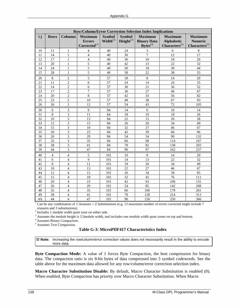
Appendix G
138 M-Class DPL Programmer’s Manual
Row/Column/Error Correction Selection Index Implicationsi j Rows Columns Maximum
ErrorsCorrected[1]
SymbolWidth[2]
SymbolHeight[3]
MaximumBinary Data
Bytes[4]
MaximumAlphabetic
Characters[5]
MaximumNumeric
Characters[5]
10 11 1 4 40 24 3 6 811 14 1 4 40 30 7 12 1712 17 1 4 40 36 10 18 2613 20 1 5 40 42 13 22 3214 24 1 5 40 50 18 30 4415 28 1 5 40 58 22 38 55
20 8 2 5 57 18 8 14 2021 11 2 6 57 24 14 24 3522 14 2 6 57 30 21 36 5223 17 2 7 57 36 27 46 6724 20 2 8 57 42 33 56 8225 23 2 10 57 48 38 67 9326 26 2 12 57 54 43 72 105
30 6 3 9 84 14 6 10 1431 8 3 11 84 18 10 18 2632 10 3 13 84 22 15 26 3833 12 3 15 84 26 20 34 4934 15 3 18 84 32 27 46 6735 20 3 23 84 42 39 66 9636 26 3 29 84 54 54 90 13237 32 3 35 84 66 68 114 16738 38 3 41 84 78 82 138 20239 44 3 47 84 90 97 162 237
40 4 4 5 101 10 8 14 2041 6 4 9 101 14 13 22 3242 8 4 11 101 18 20 34 4943 10 4 13 101 22 27 46 6744 12 4 15 101 26 34 58 8545 15 4 18 101 32 45 76 11146 20 4 23 101 42 63 106 15547 26 4 29 101 54 85 142 20848 32 4 35 101 66 106 178 26149 38 4 41 101 78 128 214 3134A 44 4 47 101 90 150 250 366
1 Can be any combination of 1∗ erasures + 2∗ substitutions (e.g. 13 maximum number of errors corrected might include 7erasures and 3 substitutions).
2 Includes 1 module width quiet zone on either side.3 Assumes the module height is 2∗ module width, and includes one module width quiet zones on top and bottom.4 Assumes Binary Compaction.5 Assumes Text Compaction.
Table G-3: MicroPDF417 Characteristics Index
� Note: Increasing the row/column/error correction values does not necessarily result in the ability to encodemore data.
Byte Compaction Mode: A value of 1 forces Byte Compaction, the best compression for binarydata. The compaction ratio is six 8-bit bytes of data compressed into 5 symbol codewords. See thetable above for the maximum data allowed for any row/column/error correction selection index.
Macro Character Substitution Disable: By default, Macro Character Substitution is enabled (0).When enabled, Byte Compaction has priority over Macro Character Substitution. When Macro
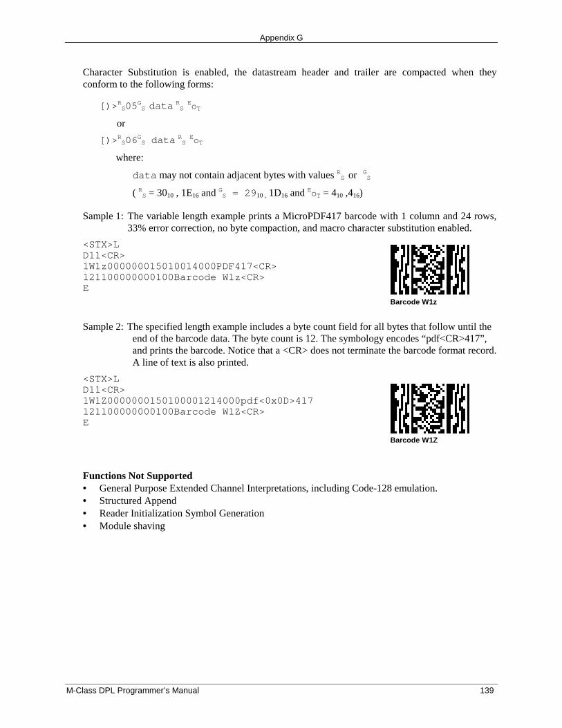
Appendix G
M-Class DPL Programmer’s Manual 139
Character Substitution is enabled, the datastream header and trailer are compacted when theyconform to the following forms:
[)>RS05GS data RS EoT
or
[)>RS06GS data RS EoT
where:
data may not contain adjacent bytes with values RS or GS
( RS = 3010 , 1E16 and GS = 2910 , 1D16 and EoT = 410 ,416)
Sample 1: The variable length example prints a MicroPDF417 barcode with 1 column and 24 rows,33% error correction, no byte compaction, and macro character substitution enabled.
<STX>LD11<CR>1W1z000000015010014000PDF417<CR>121100000000100Barcode W1z<CR>E
Barcode W1z
Sample 2: The specified length example includes a byte count field for all bytes that follow until the end of the barcode data. The byte count is 12. The symbology encodes “pdf<CR>417”, and prints the barcode. Notice that a <CR> does not terminate the barcode format record.A line of text is also printed.
<STX>LD11<CR>1W1Z0000000150100001214000pdf<0x0D>417121100000000100Barcode W1Z<CR>E
Barcode W1Z
Functions Not Supported• General Purpose Extended Channel Interpretations, including Code-128 emulation.• Structured Append• Reader Initialization Symbol Generation• Module shaving

Appendix G
140 M-Class DPL Programmer’s Manual
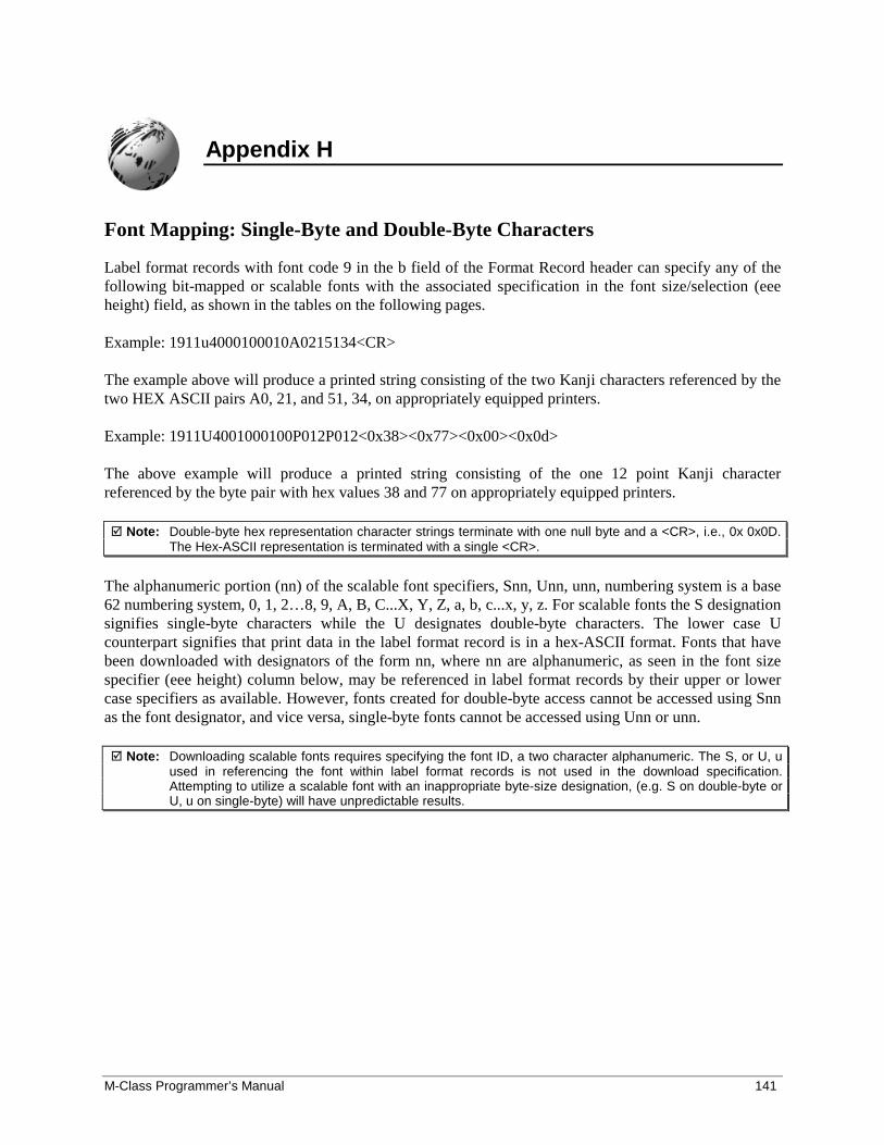
M-Class Programmer’s Manual 141
Appendix H
Font Mapping: Single-Byte and Double-Byte Characters
Label format records with font code 9 in the b field of the Format Record header can specify any of thefollowing bit-mapped or scalable fonts with the associated specification in the font size/selection (eeeheight) field, as shown in the tables on the following pages.
Example: 1911u4000100010A0215134<CR>
The example above will produce a printed string consisting of the two Kanji characters referenced by thetwo HEX ASCII pairs A0, 21, and 51, 34, on appropriately equipped printers.
Example: 1911U4001000100P012P012<0x38><0x77><0x00><0x0d>
The above example will produce a printed string consisting of the one 12 point Kanji characterreferenced by the byte pair with hex values 38 and 77 on appropriately equipped printers.
� Note: Double-byte hex representation character strings terminate with one null byte and a <CR>, i.e., 0x 0x0D.The Hex-ASCII representation is terminated with a single <CR>.
The alphanumeric portion (nn) of the scalable font specifiers, Snn, Unn, unn, numbering system is a base62 numbering system, 0, 1, 2…8, 9, A, B, C...X, Y, Z, a, b, c...x, y, z. For scalable fonts the S designationsignifies single-byte characters while the U designates double-byte characters. The lower case Ucounterpart signifies that print data in the label format record is in a hex-ASCII format. Fonts that havebeen downloaded with designators of the form nn, where nn are alphanumeric, as seen in the font sizespecifier (eee height) column below, may be referenced in label format records by their upper or lowercase specifiers as available. However, fonts created for double-byte access cannot be accessed using Snnas the font designator, and vice versa, single-byte fonts cannot be accessed using Unn or unn.
� Note: Downloading scalable fonts requires specifying the font ID, a two character alphanumeric. The S, or U, uused in referencing the font within label format records is not used in the download specification.Attempting to utilize a scalable font with an inappropriate byte-size designation, (e.g. S on double-byte orU, u on single-byte) will have unpredictable results.
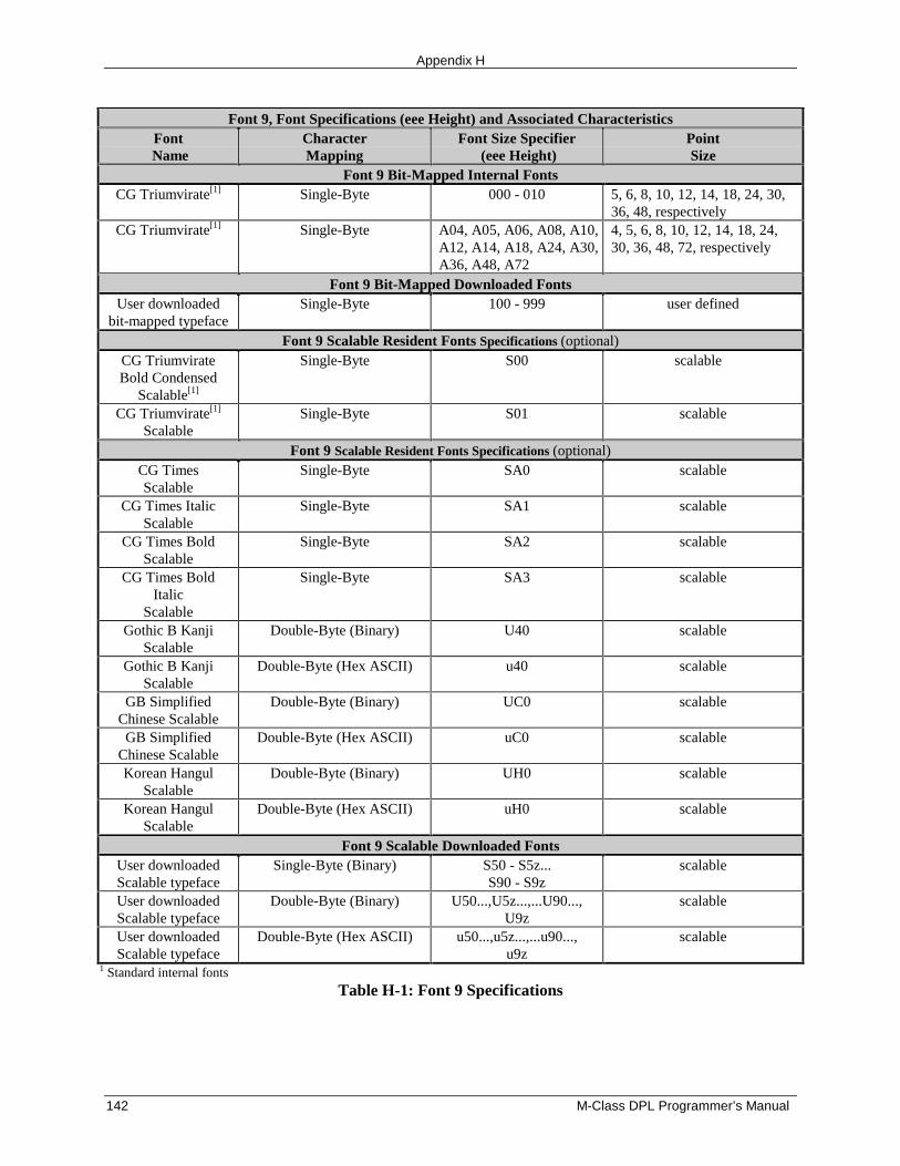
Appendix H
142 M-Class DPL Programmer’s Manual
Font 9, Font Specifications (eee Height) and Associated CharacteristicsFont
NameCharacterMapping
Font Size Specifier (eee Height)
PointSize
Font 9 Bit-Mapped Internal FontsCG Triumvirate[1] Single-Byte 000 - 010 5, 6, 8, 10, 12, 14, 18, 24, 30,
36, 48, respectivelyCG Triumvirate[1] Single-Byte A04, A05, A06, A08, A10,
A12, A14, A18, A24, A30,A36, A48, A72
4, 5, 6, 8, 10, 12, 14, 18, 24,30, 36, 48, 72, respectively
Font 9 Bit-Mapped Downloaded FontsUser downloaded
bit-mapped typefaceSingle-Byte 100 - 999 user defined
Font 9 Scalable Resident Fonts Specifications (optional)CG TriumvirateBold Condensed
Scalable[1]
Single-Byte S00 scalable
CG Triumvirate[1]
ScalableSingle-Byte S01 scalable
Font 9 Scalable Resident Fonts Specifications (optional)CG TimesScalable
Single-Byte SA0 scalable
CG Times ItalicScalable
Single-Byte SA1 scalable
CG Times BoldScalable
Single-Byte SA2 scalable
CG Times BoldItalic
Scalable
Single-Byte SA3 scalable
Gothic B KanjiScalable
Double-Byte (Binary) U40 scalable
Gothic B KanjiScalable
Double-Byte (Hex ASCII) u40 scalable
GB SimplifiedChinese Scalable
Double-Byte (Binary) UC0 scalable
GB SimplifiedChinese Scalable
Double-Byte (Hex ASCII) uC0 scalable
Korean HangulScalable
Double-Byte (Binary) UH0 scalable
Korean HangulScalable
Double-Byte (Hex ASCII) uH0 scalable
Font 9 Scalable Downloaded FontsUser downloadedScalable typeface
Single-Byte (Binary) S50 - S5z...S90 - S9z
scalable
User downloadedScalable typeface
Double-Byte (Binary) U50...,U5z...,...U90...,U9z
scalable
User downloadedScalable typeface
Double-Byte (Hex ASCII) u50...,u5z...,...u90...,u9z
scalable
1 Standard internal fonts
Table H-1: Font 9 Specifications
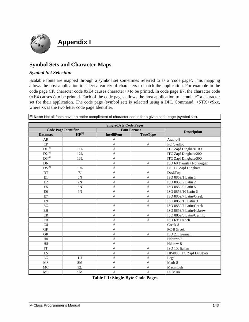
M-Class Programmer’s Manual 143
Appendix I
Symbol Sets and Character MapsSymbol Set Selection
Scalable fonts are mapped through a symbol set sometimes referred to as a ‘code page’. This mappingallows the host application to select a variety of characters to match the application. For example in thecode page CP, character code 0xE4 causes character Φ to be printed. In code page E7, the character code0xE4 causes δ to be printed. Each of the code pages allows the host application to “emulate” a characterset for their application. The code page (symbol set) is selected using a DPL Command, <STX>ySxx,where xx is the two letter code page Identifier.
� Note: Not all fonts have an entire compliment of character codes for a given code page (symbol set).
Single-Byte Code PagesCode Page Identifier Font Format
Datamax HP[1] IntelliFont TrueTypeDescription
AR √ Arabic-8CP √ √ PC CyrillicD1[4] 11L √ ITC Zapf Dingbats/100D2[4] 12L √ ITC Zapf Dingbats/200D3[4] 13L √ ITC Zapf Dingbats/300DN √ √ ISO 60 Danish / NorwegianDS[4] 10L √ PS ITC Zapf DingbatsDT 7J √ √ DeskTopE1 0N √ √ ISO 8859/1 Latin 1E2 2N √ √ ISO 8859/2 Latin 2E5 5N √ √ ISO 8859/9 Latin 5E6 6N √ √ ISO 8859/10 Latin 6E7 √ √ ISO 8859/7 Latin/GreekE9 √ ISO 8859/15 Latin 9EG √ √ ISO 8859/7 Latin/GreekEH √ ISO 8859/8 Latin/HebrewER √ √ ISO 8859/5 Latin/CyrillicFR √ √ ISO 69: FrenchG8 √ Greek-8GK √ PC-8 GreekGR √ √ ISO 21: GermanH0 √ Hebrew-7H8 √ Hebrew-8IT √ √ ISO 15: ItalianL$ √ √ HP4000 ITC Zapf DingbatsLG 1U √ √ LegalM8 8M √ √ Math-8MC 12J √ √ MacintoshMS 5M √ √ PS Math
Table I-1: Single-Byte Code Pages
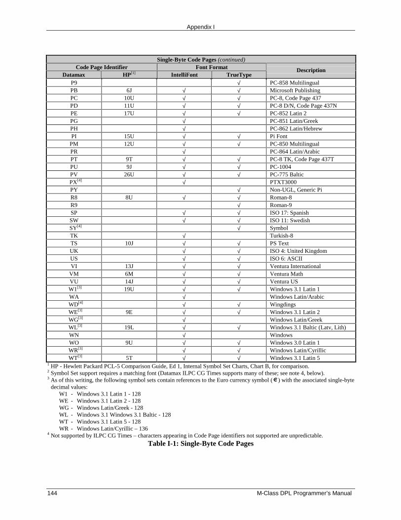
Appendix I
144 M-Class DPL Programmer’s Manual
Single-Byte Code Pages (continued)Code Page Identifier Font Format
Datamax HP[1] IntelliFont TrueTypeDescription
P9 √ PC-858 MultilingualPB 6J √ √ Microsoft PublishingPC 10U √ √ PC-8, Code Page 437PD 11U √ √ PC-8 D/N, Code Page 437NPE 17U √ √ PC-852 Latin 2PG √ PC-851 Latin/GreekPH √ PC-862 Latin/HebrewPI 15U √ √ Pi Font
PM 12U √ √ PC-850 MultilingualPR √ PC-864 Latin/ArabicPT 9T √ √ PC-8 TK, Code Page 437TPU 9J √ √ PC-1004PV 26U √ √ PC-775 BalticPX[4] √ PTXT3000PY √ Non-UGL, Generic PiR8 8U √ √ Roman-8R9 √ Roman-9SP √ √ ISO 17: SpanishSW √ √ ISO 11: SwedishSY[4] √ SymbolTK √ Turkish-8TS 10J √ √ PS TextUK √ √ ISO 4: United KingdomUS √ √ ISO 6: ASCIIVI 13J √ √ Ventura International
VM 6M √ √ Ventura MathVU 14J √ √ Ventura USW1[3] 19U √ √ Windows 3.1 Latin 1WA √ Windows Latin/ArabicWD[4] √ √ WingdingsWE[3] 9E √ √ Windows 3.1 Latin 2WG[3] √ Windows Latin/GreekWL[3] 19L √ √ Windows 3.1 Baltic (Latv, Lith)WN √ WindowsWO 9U √ √ Windows 3.0 Latin 1WR[3] √ √ Windows Latin/CyrillicWT[3] 5T √ √ Windows 3.1 Latin 5
1 HP - Hewlett Packard PCL-5 Comparison Guide, Ed 1, Internal Symbol Set Charts, Chart B, for comparison.2 Symbol Set support requires a matching font (Datamax ILPC CG Times supports many of these; see note 4, below).3 As of this writing, the following symbol sets contain references to the Euro currency symbol ( ) with the associated single-byte
decimal values:W1 - Windows 3.1 Latin 1 - 128WE - Windows 3.1 Latin 2 - 128WG - Windows Latin/Greek - 128WL - Windows 3.1 Windows 3.1 Baltic - 128WT - Windows 3.1 Latin 5 - 128WR - Windows Latin/Cyrillic – 136
4 Not supported by ILPC CG Times – characters appearing in Code Page identifiers not supported are unpredictable.
Table I-1: Single-Byte Code Pages
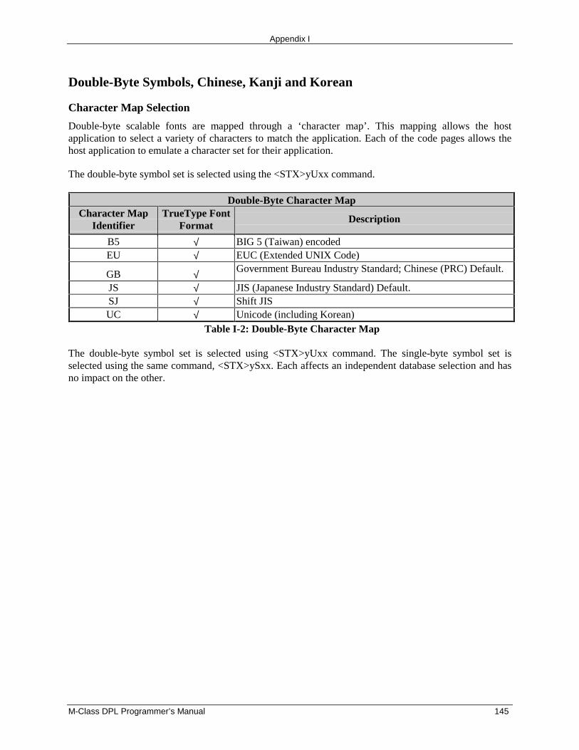
Appendix I
M-Class DPL Programmer’s Manual 145
Double-Byte Symbols, Chinese, Kanji and Korean
Character Map Selection
Double-byte scalable fonts are mapped through a ‘character map’. This mapping allows the hostapplication to select a variety of characters to match the application. Each of the code pages allows thehost application to emulate a character set for their application.
The double-byte symbol set is selected using the <STX>yUxx command.
Double-Byte Character MapCharacter Map
IdentifierTrueType Font
FormatDescription
B5 √ BIG 5 (Taiwan) encodedEU √ EUC (Extended UNIX Code)
GB √ Government Bureau Industry Standard; Chinese (PRC) Default.
JS √ JIS (Japanese Industry Standard) Default.SJ √ Shift JISUC √ Unicode (including Korean)
Table I-2: Double-Byte Character Map
The double-byte symbol set is selected using <STX>yUxx command. The single-byte symbol set isselected using the same command, <STX>ySxx. Each affects an independent database selection and hasno impact on the other.
Appendix I
146 M-Class DPL Programmer’s Manual
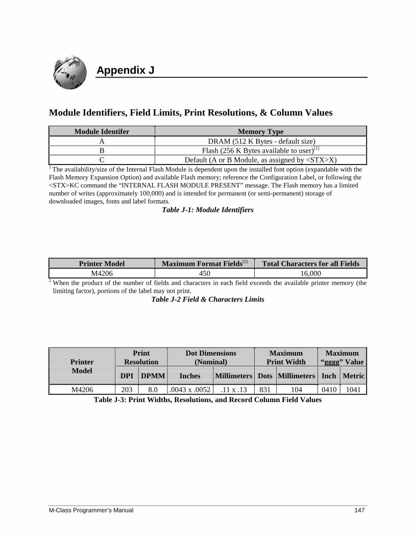
M-Class Programmer’s Manual 147
Appendix J
Module Identifiers, Field Limits, Print Resolutions, & Column Values
Module Identifer Memory TypeA DRAM (512 K Bytes - default size)B Flash (256 K Bytes available to user)[1]
C Default (A or B Module, as assigned by <STX>X)1 The availability/size of the Internal Flash Module is dependent upon the installed font option (expandable with theFlash Memory Expansion Option) and available Flash memory; reference the Configuration Label, or following the<STX>KC command the “INTERNAL FLASH MODULE PRESENT” message. The Flash memory has a limitednumber of writes (approximately 100,000) and is intended for permanent (or semi-permanent) storage ofdownloaded images, fonts and label formats.
Table J-1: Module Identifiers
Printer Model Maximum Format Fields[2] Total Characters for all FieldsM4206 450 16,000
2 When the product of the number of fields and characters in each field exceeds the available printer memory (thelimiting factor), portions of the label may not print.
Table J-2 Field & Characters Limits
PrintResolution
Dot Dimensions(Nominal)
MaximumPrint Width
Maximum“gggg” ValuePrinter
ModelDPI DPMM Inches Millimeters Dots Millimeters Inch Metric
M4206 203 8.0 .0043 x .0052 .11 x .13 831 104 0410 1041Table J-3: Print Widths, Resolutions, and Record Column Field Values

Appendix J
148 M-Class DPL Programmer’s Manual
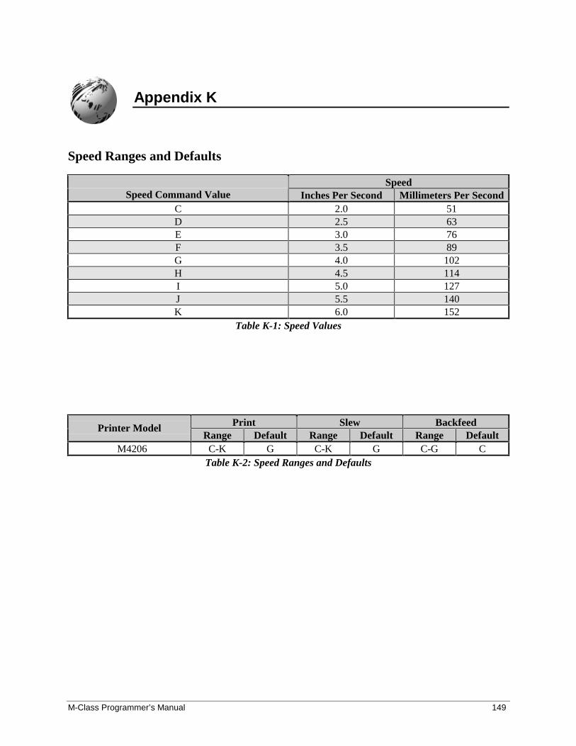
M-Class Programmer’s Manual 149
Appendix K
Speed Ranges and Defaults
SpeedSpeed Command Value Inches Per Second Millimeters Per Second
C 2.0 51D 2.5 63E 3.0 76F 3.5 89G 4.0 102H 4.5 114I 5.0 127J 5.5 140K 6.0 152
Table K-1: Speed Values
Print Slew BackfeedPrinter ModelRange Default Range Default Range Default
M4206 C-K G C-K G C-G CTable K-2: Speed Ranges and Defaults

Appendix K
150 M-Class DPL Programmer’s Manual
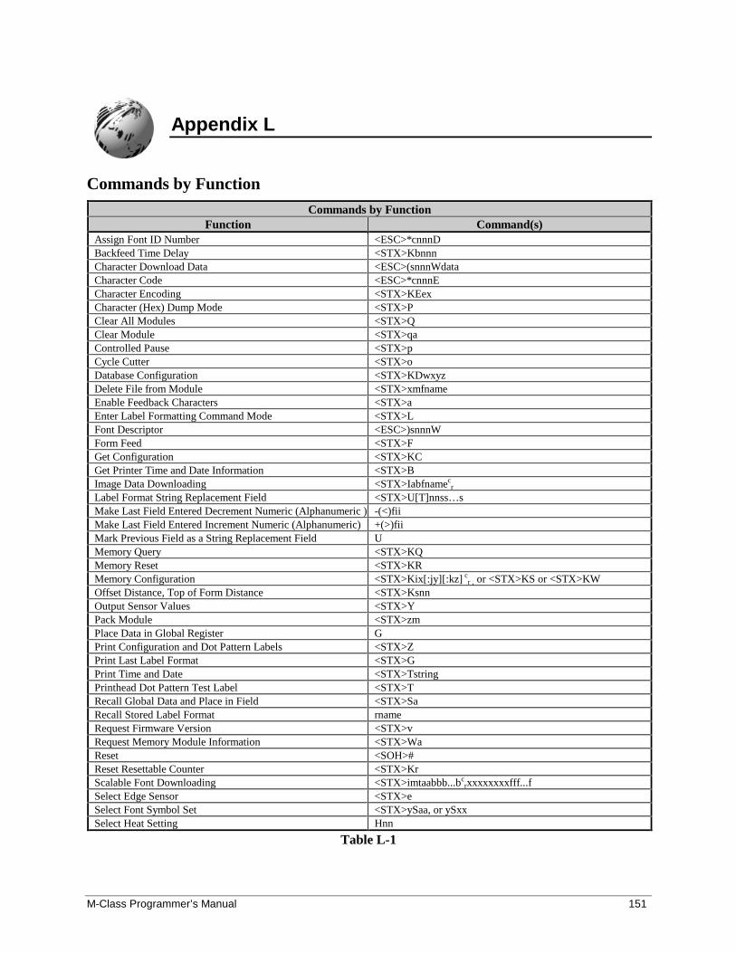
M-Class Programmer’s Manual 151
Appendix L
Commands by FunctionCommands by Function
Function Command(s)Assign Font ID Number <ESC>*cnnnDBackfeed Time Delay <STX>KbnnnCharacter Download Data <ESC>(snnnWdataCharacter Code <ESC>*cnnnECharacter Encoding <STX>KEexCharacter (Hex) Dump Mode <STX>PClear All Modules <STX>QClear Module <STX>qaControlled Pause <STX>pCycle Cutter <STX>oDatabase Configuration <STX>KDwxyzDelete File from Module <STX>xmfnameEnable Feedback Characters <STX>aEnter Label Formatting Command Mode <STX>LFont Descriptor <ESC>)snnnWForm Feed <STX>FGet Configuration <STX>KCGet Printer Time and Date Information <STX>BImage Data Downloading <STX>Iabfnamec
r
Label Format String Replacement Field <STX>U[T]nnss…sMake Last Field Entered Decrement Numeric (Alphanumeric ) -(<)fiiMake Last Field Entered Increment Numeric (Alphanumeric) +(>)fiiMark Previous Field as a String Replacement Field UMemory Query <STX>KQMemory Reset <STX>KRMemory Configuration <STX>Kix[:jy][:kz] c
r , or <STX>KS or <STX>KWOffset Distance, Top of Form Distance <STX>KsnnOutput Sensor Values <STX>YPack Module <STX>zmPlace Data in Global Register GPrint Configuration and Dot Pattern Labels <STX>ZPrint Last Label Format <STX>GPrint Time and Date <STX>TstringPrinthead Dot Pattern Test Label <STX>TRecall Global Data and Place in Field <STX>SaRecall Stored Label Format rnameRequest Firmware Version <STX>vRequest Memory Module Information <STX>WaReset <SOH>#Reset Resettable Counter <STX>KrScalable Font Downloading <STX>imtaabbb...bc
rxxxxxxxxfff...fSelect Edge Sensor <STX>eSelect Font Symbol Set <STX>ySaa, or ySxxSelect Heat Setting Hnn
Table L-1
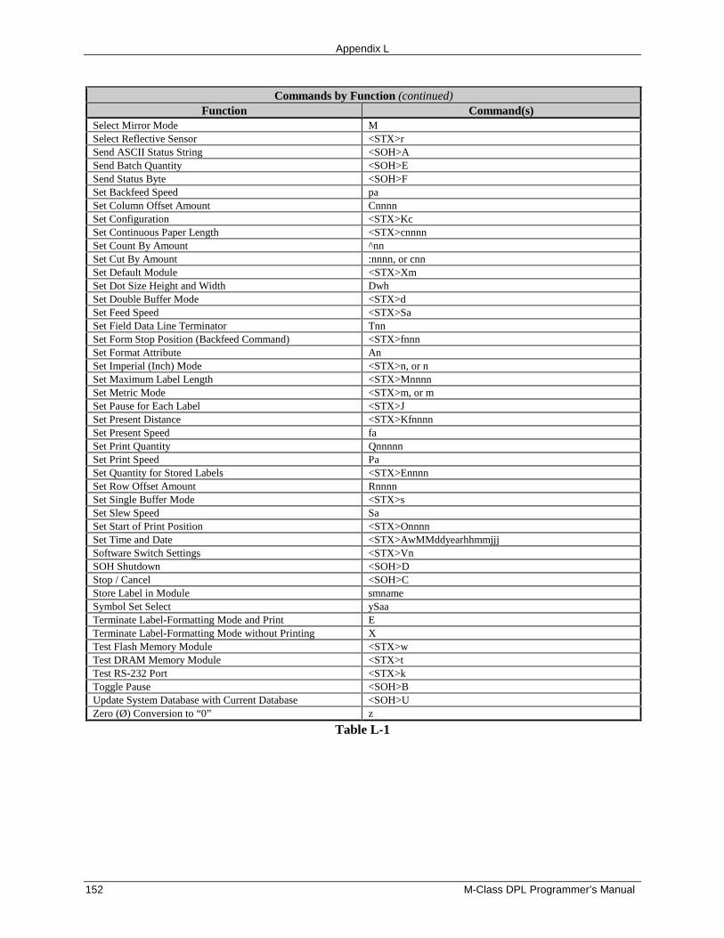
Appendix L
152 M-Class DPL Programmer’s Manual
Commands by Function (continued)Function Command(s)
Select Mirror Mode MSelect Reflective Sensor <STX>rSend ASCII Status String <SOH>ASend Batch Quantity <SOH>ESend Status Byte <SOH>FSet Backfeed Speed paSet Column Offset Amount CnnnnSet Configuration <STX>KcSet Continuous Paper Length <STX>cnnnnSet Count By Amount ^nnSet Cut By Amount :nnnn, or cnnSet Default Module <STX>XmSet Dot Size Height and Width DwhSet Double Buffer Mode <STX>dSet Feed Speed <STX>SaSet Field Data Line Terminator TnnSet Form Stop Position (Backfeed Command) <STX>fnnnSet Format Attribute AnSet Imperial (Inch) Mode <STX>n, or nSet Maximum Label Length <STX>MnnnnSet Metric Mode <STX>m, or mSet Pause for Each Label <STX>JSet Present Distance <STX>KfnnnnSet Present Speed faSet Print Quantity QnnnnnSet Print Speed PaSet Quantity for Stored Labels <STX>EnnnnSet Row Offset Amount RnnnnSet Single Buffer Mode <STX>sSet Slew Speed SaSet Start of Print Position <STX>OnnnnSet Time and Date <STX>AwMMddyearhhmmjjjSoftware Switch Settings <STX>VnSOH Shutdown <SOH>DStop / Cancel <SOH>CStore Label in Module smnameSymbol Set Select ySaaTerminate Label-Formatting Mode and Print ETerminate Label-Formatting Mode without Printing XTest Flash Memory Module <STX>wTest DRAM Memory Module <STX>tTest RS-232 Port <STX>kToggle Pause <SOH>BUpdate System Database with Current Database <SOH>UZero (Ø) Conversion to “0” z
Table L-1
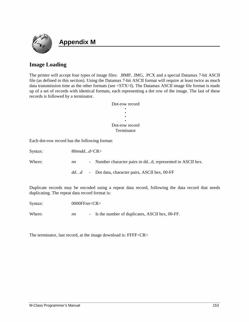
M-Class Programmer’s Manual 153
Appendix M
Image Loading
The printer will accept four types of image files: .BMP, .IMG, .PCX and a special Datamax 7-bit ASCIIfile (as defined in this section). Using the Datamax 7-bit ASCII format will require at least twice as muchdata transmission time as the other formats (see <STX>I). The Datamax ASCII image file format is madeup of a set of records with identical formats, each representing a dot row of the image. The last of theserecords is followed by a terminator.
Dot-row record••••
Dot-row recordTerminator
Each dot-row record has the following format:
Syntax: 80nndd...d<CR>
Where: nn - Number character pairs in dd...d, represented in ASCII hex.
dd…d - Dot data, character pairs, ASCII hex, 00-FF
Duplicate records may be encoded using a repeat data record, following the data record that needsduplicating. The repeat data record format is:
Syntax: 0000FFnn<CR>
Where: nn - Is the number of duplicates, ASCII hex, 00-FF.
The terminator, last record, at the image download is: FFFF<CR>
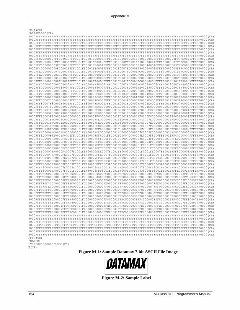
Appendix M
154 M-Class DPL Programmer’s Manual
^BqA(CR)^BIAAFLOGO(CR)8030FFFFFFFFFFFFFFFFFFFFFFFFFFFFFFFFFFFFFFFFFFFFFFFFFFFFFFFFFFFFFFFFFFFFFFFFFFFFFFFFFFFFFFFFFFFF0000(CR)8030FFFFFFFFFFFFFFFFFFFFFFFFFFFFFFFFFFFFFFFFFFFFFFFFFFFFFFFFFFFFFFFFFFFFFFFFFFFFFFFFFFFFFFFFFFFF0000(CR)8030FFFFFFFFFFFFFFFFFFFFFFFFFFFFFFFFFFFFFFFFFFFFFFFFFFFFFFFFFFFFFFFFFFFFFFFFFFFFFFFFFFFFFFFFFFFF0000(CR)8030FFFFFFFFFFFFFFFFFFFFFFFFFFFFFFFFFFFFFFFFFFFFFFFFFFFFFFFFFFFFFFFFFFFFFFFFFFFFFFFFFFFFFFFFFFFF0000(CR)8030FFFFFFFFFFFFFFFFFFFFFFFFFFFFFFFFFFFFFFFFFFFFFFFFFFFFFFFFFFFFFFFFFFFFFFFFFFFFFFFFFFFFFFFFFFFF0000(CR)8030FFFFFFFFFFFFFFFFFFFFFFFFFFFFFFFFFFFFFFFFFFFFFFFFFFFFFFFFFFFFFFFFFFFFFFFFFFFFFFFFFFFFFFFFFFFF0000(CR)8030FFFFFFFFFFFFFFFFFFFFFFFFFFFFFFFFFFFFFFFFFFFFFFFFFFFFFFFFFFFFFFFFFFFFFFFFFFFFFFFFFFFFFFFFFFFF0000(CR)8030FFC00000007FFC0003FFFFC001FC0001FC0003FFFFC0018000FFC001FF8000C0003FFFFE000000FFFFE0001FFFFF0000(CR)8030FFC00000000FFC0003FFFFC001FC0001FC0003FFFFC0018000FFC001FF800040001FFFFE0000007FFFC0001FFFFF0000(CR)8030FFC000000003FC0001FFFFC001FC0001FC0001FFFFC0018000FFC001FF800040001FFFFE0000003FFFC0001FFFFF0000(CR)8030FFC000000000FC0001FFFFC001FE0001FE0001FFFFC00180007FC000FF800060001FFFFE0000003FFFC0003FFFFF0000(CR)8030FFE0000000007E0001FFFFC001FE0001FE0001FFFFC00180007FC000FFC00060000FFFFE0000001FFFC0003FFFFF0000(CR)8030FFE0000000003E0000FFFFC001FE0000FE0000FFFFC00180007FC0007FC00020000FFFFE0000001FFF80003FFFFF0000(CR)8030FFE0000000001E0000FFFFC001FE0000FF0000FFFFC001C0007FC0007FC00030000FFFFE0010000FFF80003FFFFF0000(CR)8030FFE0000000000F0000FFFFC001FE0000FF0000FFFFC001C0007FC0007FC00030000FFFFE00180007FF80007FFFFF0000(CR)8030FFE0000000000700007FFFC001FF0000FF80007FFFC001C0007FC0003FC000380007FFFE00180007FF80007FFFFF0000(CR)8030FFF0000000000380007FFFC001FF0000FF80007FFFC001C0003FC0003FE000380007FFFE001C0003FF80007FFFFF0000(CR)8030FFF0000000000380007FFFC001FF0000FF80007FFFC001C0003FC0003FE000380007FFFE001E0003FF80007FFFFF0000(CR)8030FFF0000000000180003FFFC001FF00007FC0003FFFC001C0003FC0001FE0001C0003FFFE001E0001FF0000FFFFFF0000(CR)8030FFF00000000001C0003FFFC001FF00007FC0003FFFC001E0003FC0001FE0001C0003FFFE001F0000FF0000FFFFFF0000(CR)8030FFF00007C00000C0003FFFC001FF00007FE0003FFFC001E0003FC0000FF0001E0003FFFE001F0000FF0000FFFFFF0000(CR)8030FFF80007F80000E0001FFFC001FF80007FE0001FFFC001E0003FC0000FF0001E0001FFFE001F80007F0000FFFFFF0000(CR)8030FFF80007FC0000E00000000001FF80007FE00000000001E0001FC0000FF0001E00000000001FC0007F0000FFFFFF0000(CR)8030FFF80007FE0000600000000001FF80003FF00000000001E0001FC00007F0000F00000000001FC0003F0001FFFFFF0000(CR)8030FFF80003FF0000700000000001FF80003FF00000000001F0001FC00007F0000F00000000001FE0001E0001FFFFFF0000(CR)8030FFF80003FF0000700000000001FF80003FF00000000001F0001FC00007F8000F00000000001FE0001E0001FFFFFF0000(CR)8030FFFC0001FFC0003C0000000001FFE0001FFE0000000001F8000FC00000FC0007E0000000001FFE00000003FFFFFF0000(CR)8030FFFE0001FFC0001E0000000001FFE0001FFE0000000001F8000FC00000FC0007E0000000001FFF00000003FFFFFF0000(CR)8030FFFE0001FFC0001E0000000001FFE0001FFE0000000001F8000FC00000FC0007F0000000001FFF00000007FFFFFF0000(CR)8030FFFE0000FFC0001F0000000001FFE0000FFF0000000001F8000FC000007C0003F0000000001FFF80000007FFFFFF0000(CR)8030FFFE0000FFC0001F0000000001FFE0000FFF0000000001FC0007C000007E0003F0000000001FFF80000007FFFFFF0000(CR)8030FFFE0000FFE0001F0001FFC001FFE0000FFF8001FFC001FC0007C000003E0003F8000FFE001FFFC0000007FFFFFF0000(CR)8030FFFE0000FFE0000F8001FFC001FFF0000FFF8000FFC001FC0007C000003E0003F8000FFE001FFFE000000FFFFFFF0000(CR)8030FFFF0000FFE0000F8000FFC001FFF0000FFF8000FFC001FC0007C000003E0003F8000FFE001FFFE000000FFFFFFF0000(CR)8030FFFF0000FFE0000F8000FFC001FFF00007FFC000FFC001FC0007C000001F0001FC000FFE001FFFF000000FFFFFFF0000(CR)8030FFFF00007FE0000FC000FFC001FFF00007FFC0007FC001FE0007C002001F0001FC0007FE001FFFF000000FFFFFFF0000(CR)8030FFFF00007FF0000FC0007FC001FFF00007FFE0007FC001FE0003C002001F0001FE0007FE001FFFF800000FFFFFFF0000(CR)8030FFFF00007FF0000FE0007FC001FFF80007FFE0007FC001FE0003C003000F0001FE0007FE001FFFFC00001FFFFFFF0000(CR)8030FFFF80007FF00007E0007FC001FFF80007FFE0003FC001FE0003C003000F0001FE0003FE001FFFFC00001FFFFFFF0000(CR)8030FFFF80007FF00007E0003FC001FFF80003FFF0003FC001FE0003C00300078001FF0003FE001FFFFE00001FFFFFFF0000(CR)8030FFFF80003FF00007F0003FC001FFF80003FFF0003FC001FE0003C00380078000FF0003FE001FFFFE00001FFFFFFF0000(CR)8030FFFF80003FF80007F0003FC001FFF80003FFF0001FC001FF0003C00380078000FF8001FE001FFFFE00001FFFFFFF0000(CR)8030FFFF80003FF80007F0001FC001FFF80003FFF8001FC001FF0001C003C0038000FF8001FE001FFFFE00001FFFFFFF0000(CR)8030FFFFFFC0000000007FFC000001F80000000000FC000001FFF0000003FFE0000007FFC000001FFFC0003F80007FFF0000(CR)8030FFFFFFE000000000FFFC000001F80000000000FE000001FFF8000003FFE0000007FFE000001FFFC0003FC0003FFF0000(CR)8030FFFFFFF000000000FFFE000001F80000000000FE000001FFF8000003FFF0000007FFE000001FFFC0003FC0003FFF0000(CR)8030FFFFFFFC00000000FFFE000001FC0000000000FE000001FFF8000003FFF0000007FFE000001FFFC0003FE0001FFF0000(CR)8030FFFFFFFE00000000FFFE000001FC00000000007F000001FFF8000003FFF0000007FFF000001FFFC0003FE0001FFF0000(CR)8030FFFFFFFF00000001FFFF000001FC00000000007F000001FFF8000003FFF8000007FFF000001FFF80003FF0000FFF0000(CR)8030FFFFFFFFC0000001FFFF000001FC00000000007F000001FFF8000003FFF8000003FFF800001FFF80007FF0000FFF0000(CR)8030FFFFFFFFE0000003FFFF800001FC00000000007F800001FFFC000003FFF8000003FFF800001FFF80007FF80007FF0000(CR)8030FFFFFFFFF0000007FFFF800001FC00000000007F800001FFFC000003FFFC000003FFF800001FFF80007FF80007FF0000(CR)8030FFFFFFFFF800000FFFFF800001FE00000000003FC00001FFFC000003FFFC000003FFFC00001FFF00007FFC0003FF0000(CR)8030FFFFFFFFFE00001FFFFFC00001FE00000000003FC00001FFFC000003FFFE000003FFFC00001FFF00007FFC0003FF0000(CR)8030FFFFFFFFFF00007FFFFFC00001FE00000000003FC00001FFFC000003FFFE000003FFFE00001FFF00007FFE0001FF0000(CR)8030FFFFFFFFFF8003FFFFFFC00001FE00000000003FE00001FFFC000003FFFF000003FFFE00001FFF00007FFE0001FF0000(CR)8030FFFFFFFFFFFFFFFFFFFFFFFFFFFFFFFFFFFFFFFFFFFFFFFFFFFFFFFFFFFFFFFFFFFFFFFFFFFFFFFFFFFFFFFFFFFF0000(CR)8030FFFFFFFFFFFFFFFFFFFFFFFFFFFFFFFFFFFFFFFFFFFFFFFFFFFFFFFFFFFFFFFFFFFFFFFFFFFFFFFFFFFFFFFFFFFF0000(CR)8030FFFFFFFFFFFFFFFFFFFFFFFFFFFFFFFFFFFFFFFFFFFFFFFFFFFFFFFFFFFFFFFFFFFFFFFFFFFFFFFFFFFFFFFFFFFF0000(CR)8030FFFFFFFFFFFFFFFFFFFFFFFFFFFFFFFFFFFFFFFFFFFFFFFFFFFFFFFFFFFFFFFFFFFFFFFFFFFFFFFFFFFFFFFFFFFF0000(CR)8030FFFFFFFFFFFFFFFFFFFFFFFFFFFFFFFFFFFFFFFFFFFFFFFFFFFFFFFFFFFFFFFFFFFFFFFFFFFFFFFFFFFFFFFFFFFF0000(CR)8030FFFFFFFFFFFFFFFFFFFFFFFFFFFFFFFFFFFFFFFFFFFFFFFFFFFFFFFFFFFFFFFFFFFFFFFFFFFFFFFFFFFFFFFFFFFF0000(CR)8030FFFFFFFFFFFFFFFFFFFFFFFFFFFFFFFFFFFFFFFFFFFFFFFFFFFFFFFFFFFFFFFFFFFFFFFFFFFFFFFFFFFFFFFFFFFF0000(CR)FFFF(CR)^BL(CR)1Y1100000000000LOGO(CR)E(CR)
Figure M-1: Sample Datamax 7-bit ASCII File Image
Figure M-2: Sample Label
M-Class Programmer’s Manual 155
Appendix N
UPC-A and EAN-13: Variable Price and Weight Bar Code
The EAN/UPC standard allows for an additional checksum to be generated in the middle of the bar codebased on the data. This is used when the price or weight of an item is embedded into the bar code data(commonly used in the food industry).
For the printer to generate this checksum, a ‘V’ must be placed in the data stream in the position thechecksum is requested. If the ‘V’ is placed in the 6th position for UPC-A or the 7th position for EAN-13,a checksum will be generated using the next five digits in the data stream. If the ‘V’ is placed in the 7thposition for UPC-A or the 8th position for EAN-13, a checksum will be generated using the next fourdigits in the data stream. The checksum is generated per the EAN/UPC bar code standard.
The following are examples of variable price and weight bar codes:
1B110000200020012345V01199
This record format prints a UPC-A bar code with the variable price checksum in the sixth position.
1B1100002000200123456V0150
This record format prints a UPC-A bar code with the variable price checksum in the seventh position.
1F1100002000200123456V01199
This record format prints an EAN-13 bar code with the variable price checksum in the seventh position.
1F11000020002001234567V0150
This record format prints an EAN-13 bar code with the variable price checksum in the eighth position.

Appendix N
156 M-Class DPL Programmer’s Manual
M-Class Programmer’s Manual 157
Appendix O
International Language Print Capability (ILPC) Programming Examples
ILPC, offered as a field upgrade or a factory installable option, allows the printing of non-Englishcharacter sets, available with Western European language support (CG TIMES), KANJI languagesupport (GOTHIC B / GOTHIC E), and Chinese language support (SIMPLIFIED GB). All of the featuresare embedded in the printer resident firmware and accessible through DPL thus eliminating excessivedownload time of bitmapped characters. Using scalable technology licensed from AGFA, this firmwareallows users to print smooth characters in sizes from 4pt (1.4 mm) to 999pt (350 mm) in over 40languages. Consult Appendix I for code page selections. Specific details regarding which characters aresupported in each option can be obtained through Datamax Technical Support at 407-523-5540.
ILPC - CG TIMES Option
The CG Times Option is a single-byte scalable font consisting of four typefaces in 38 Western Europeanlanguages. This option contains over 900 unique characters in each of the four typefaces from the CGTimes typeface family, Normal, Italic, Bold, and Bold Italic. Single-byte scalable fonts are selected usinga print format record (see Generating Label Formats and Appendix H for details).
Scalable CG TIMES Font Code (‘eee’ field): SA0 - CG TIMESSA1 - CG TIMES ITALICSA2 - CG TIMES BOLDSA3 - CG TIMES BOLD ITALIC
Sample Greek DPL file and resulting label:
<02>L<CR>D11<CR>ySWG<CR>1911SA003600020P020P020(WG) Greek Characters from<CR>1911SA003000085P020P020the internal Symbol Set,<CR>1911SA002400085P020P020font code SA0<CR>1911SA001500050P020P020<ca><e1><eb><f9><f3><ef><f1><df><f3><e1><f4><e5><20><d3><f5><ed><dd><e4><f1><e9><ef><20><CR>1911SA001100100P020P020<f4><f9><e3><20><c5><f4><e1><df><f1><f9><e3><20><f4><e7><f2><CR>1911SA000700140P020P020Datamax<CR>1X1100000100020B365190005005<CR>Q0002<CR>E<CR>
� Note: The notation “<xx>“ in this DPL file should be interpreted by the reader as representing the hexadecimalvalue of the character sent to the printer.
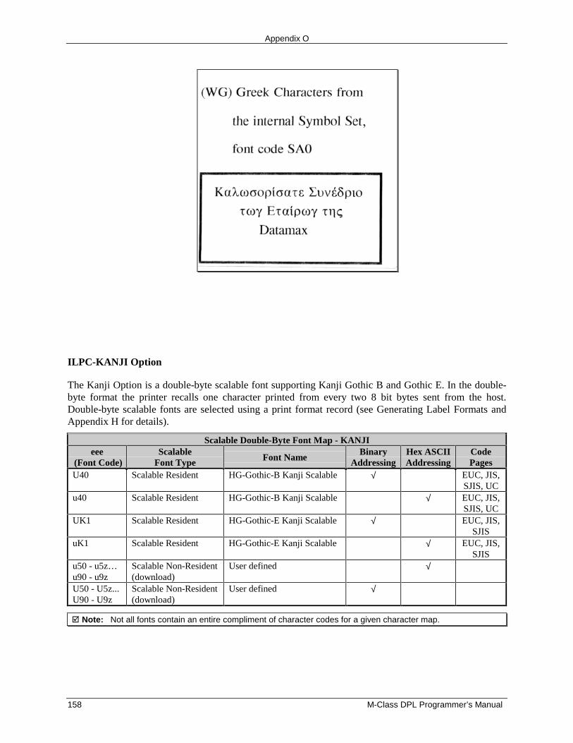
Appendix O
158 M-Class DPL Programmer’s Manual
ILPC-KANJI Option
The Kanji Option is a double-byte scalable font supporting Kanji Gothic B and Gothic E. In the double-byte format the printer recalls one character printed from every two 8 bit bytes sent from the host.Double-byte scalable fonts are selected using a print format record (see Generating Label Formats andAppendix H for details).
Scalable Double-Byte Font Map - KANJIeee
(Font Code)Scalable
Font Type Font NameBinary
AddressingHex ASCIIAddressing
CodePages
U40 Scalable Resident HG-Gothic-B Kanji Scalable √ EUC, JIS,SJIS, UC
u40 Scalable Resident HG-Gothic-B Kanji Scalable √ EUC, JIS,SJIS, UC
UK1 Scalable Resident HG-Gothic-E Kanji Scalable √ EUC, JIS,SJIS
uK1 Scalable Resident HG-Gothic-E Kanji Scalable √ EUC, JIS,SJIS
u50 - u5z…u90 - u9z
Scalable Non-Resident(download)
User defined √
U50 - U5z...U90 - U9z
Scalable Non-Resident(download)
User defined √
� Note: Not all fonts contain an entire compliment of character codes for a given character map.
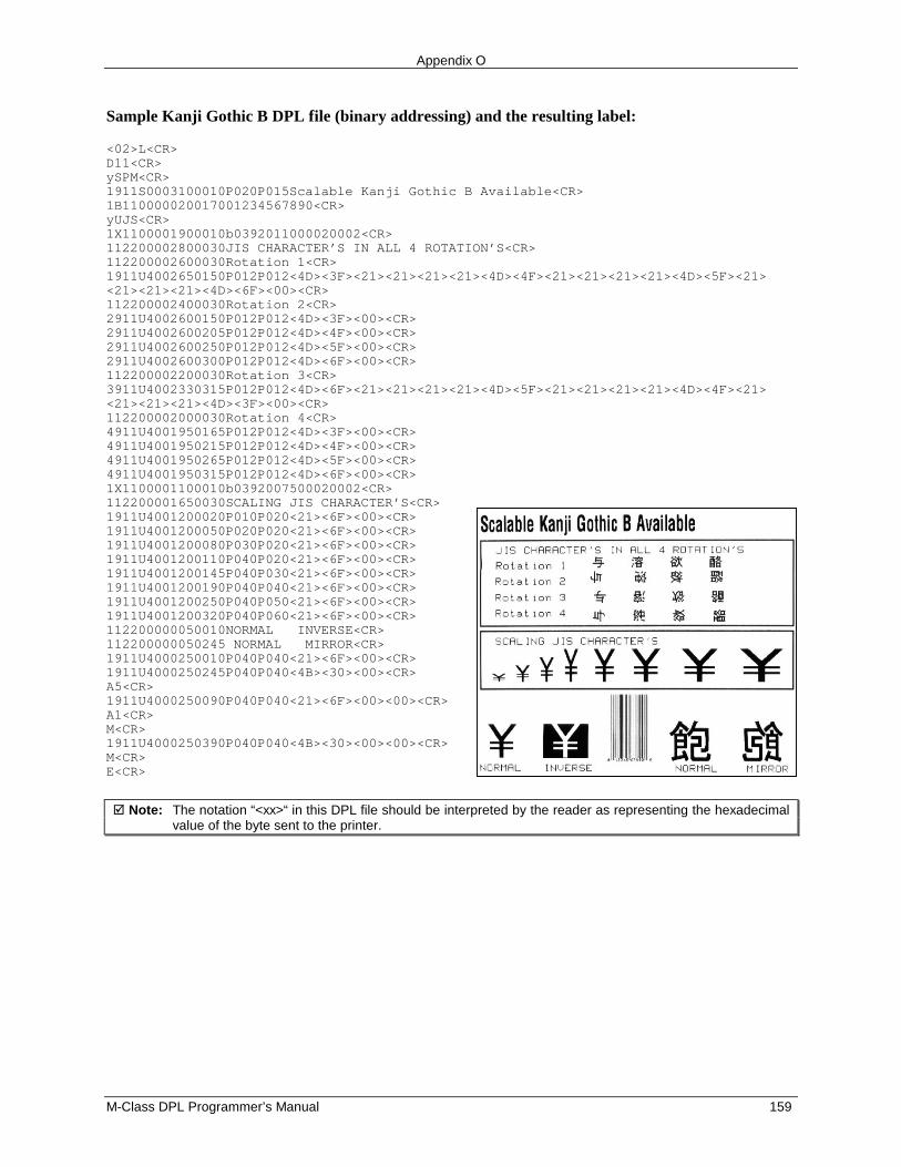
Appendix O
M-Class DPL Programmer’s Manual 159
Sample Kanji Gothic B DPL file (binary addressing) and the resulting label:
<02>L<CR>D11<CR>ySPM<CR>1911S0003100010P020P015Scalable Kanji Gothic B Available<CR>1B110000020017001234567890<CR>yUJS<CR>1X1100001900010b0392011000020002<CR>112200002800030JIS CHARACTER’S IN ALL 4 ROTATION’S<CR>112200002600030Rotation 1<CR>1911U4002650150P012P012<4D><3F><21><21><21><21><4D><4F><21><21><21><21><4D><5F><21><21><21><21><4D><6F><00><CR>112200002400030Rotation 2<CR>2911U4002600150P012P012<4D><3F><00><CR>2911U4002600205P012P012<4D><4F><00><CR>2911U4002600250P012P012<4D><5F><00><CR>2911U4002600300P012P012<4D><6F><00><CR>112200002200030Rotation 3<CR>3911U4002330315P012P012<4D><6F><21><21><21><21><4D><5F><21><21><21><21><4D><4F><21><21><21><21><4D><3F><00><CR>112200002000030Rotation 4<CR>4911U4001950165P012P012<4D><3F><00><CR>4911U4001950215P012P012<4D><4F><00><CR>4911U4001950265P012P012<4D><5F><00><CR>4911U4001950315P012P012<4D><6F><00><CR>1X1100001100010b0392007500020002<CR>112200001650030SCALING JIS CHARACTER’S<CR>1911U4001200020P010P020<21><6F><00><CR>1911U4001200050P020P020<21><6F><00><CR>1911U4001200080P030P020<21><6F><00><CR>1911U4001200110P040P020<21><6F><00><CR>1911U4001200145P040P030<21><6F><00><CR>1911U4001200190P040P040<21><6F><00><CR>1911U4001200250P040P050<21><6F><00><CR>1911U4001200320P040P060<21><6F><00><CR>112200000050010NORMAL INVERSE<CR>112200000050245 NORMAL MIRROR<CR>1911U4000250010P040P040<21><6F><00><CR>1911U4000250245P040P040<4B><30><00><CR>A5<CR>1911U4000250090P040P040<21><6F><00><00><CR>A1<CR>M<CR>1911U4000250390P040P040<4B><30><00><00><CR>M<CR>E<CR>
� Note: The notation “<xx>“ in this DPL file should be interpreted by the reader as representing the hexadecimalvalue of the byte sent to the printer.
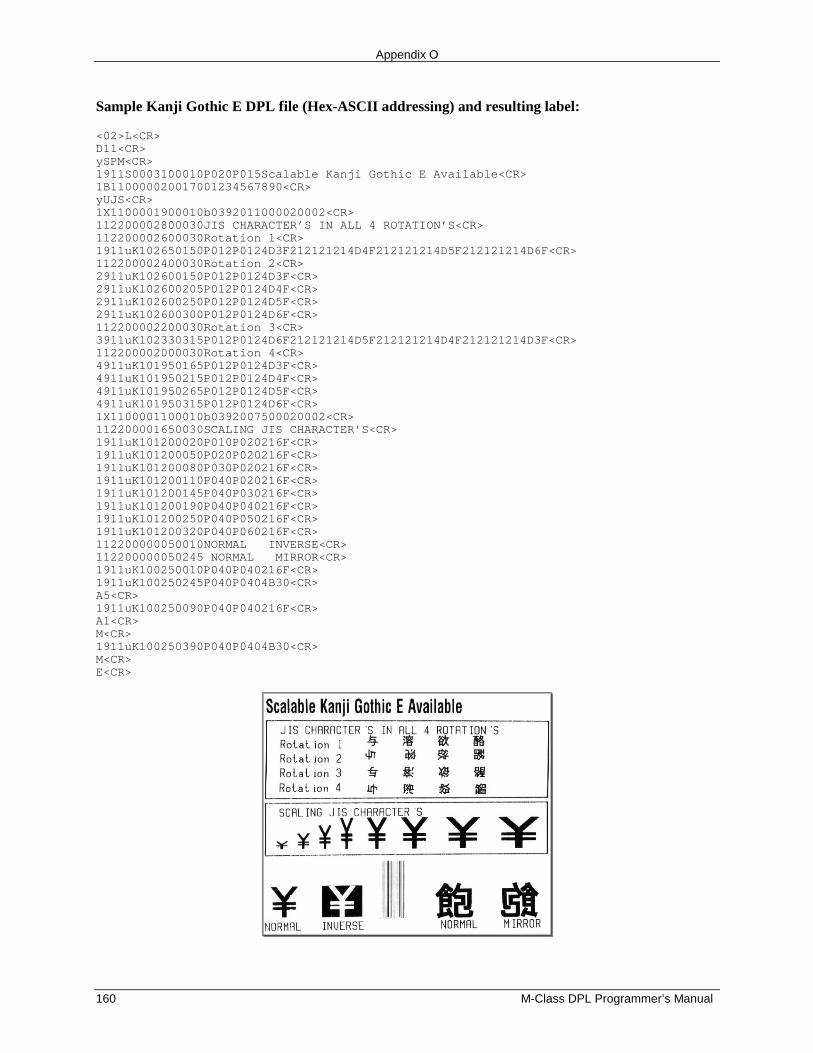
Appendix O
160 M-Class DPL Programmer’s Manual
Sample Kanji Gothic E DPL file (Hex-ASCII addressing) and resulting label:
<02>L<CR>D11<CR>ySPM<CR>1911S0003100010P020P015Scalable Kanji Gothic E Available<CR>1B110000020017001234567890<CR>yUJS<CR>1X1100001900010b0392011000020002<CR>112200002800030JIS CHARACTER’S IN ALL 4 ROTATION’S<CR>112200002600030Rotation 1<CR>1911uK102650150P012P0124D3F212121214D4F212121214D5F212121214D6F<CR>112200002400030Rotation 2<CR>2911uK102600150P012P0124D3F<CR>2911uK102600205P012P0124D4F<CR>2911uK102600250P012P0124D5F<CR>2911uK102600300P012P0124D6F<CR>112200002200030Rotation 3<CR>3911uK102330315P012P0124D6F212121214D5F212121214D4F212121214D3F<CR>112200002000030Rotation 4<CR>4911uK101950165P012P0124D3F<CR>4911uK101950215P012P0124D4F<CR>4911uK101950265P012P0124D5F<CR>4911uK101950315P012P0124D6F<CR>1X1100001100010b0392007500020002<CR>112200001650030SCALING JIS CHARACTER’S<CR>1911uK101200020P010P020216F<CR>1911uK101200050P020P020216F<CR>1911uK101200080P030P020216F<CR>1911uK101200110P040P020216F<CR>1911uK101200145P040P030216F<CR>1911uK101200190P040P040216F<CR>1911uK101200250P040P050216F<CR>1911uK101200320P040P060216F<CR>112200000050010NORMAL INVERSE<CR>112200000050245 NORMAL MIRROR<CR>1911uK100250010P040P040216F<CR>1911uK100250245P040P0404B30<CR>A5<CR>1911uK100250090P040P040216F<CR>A1<CR>M<CR>1911uK100250390P040P0404B30<CR>M<CR>E<CR>
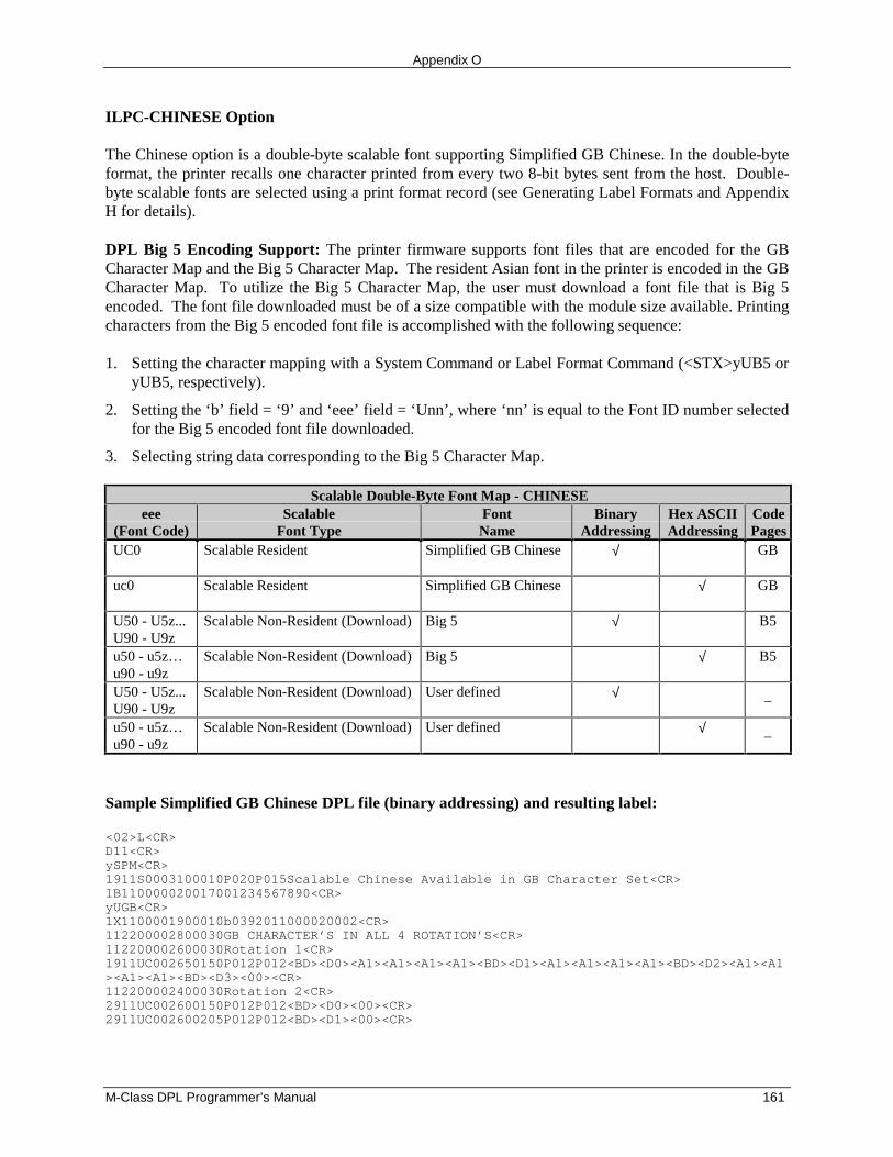
Appendix O
M-Class DPL Programmer’s Manual 161
ILPC-CHINESE Option
The Chinese option is a double-byte scalable font supporting Simplified GB Chinese. In the double-byteformat, the printer recalls one character printed from every two 8-bit bytes sent from the host. Double-byte scalable fonts are selected using a print format record (see Generating Label Formats and AppendixH for details).
DPL Big 5 Encoding Support: The printer firmware supports font files that are encoded for the GBCharacter Map and the Big 5 Character Map. The resident Asian font in the printer is encoded in the GBCharacter Map. To utilize the Big 5 Character Map, the user must download a font file that is Big 5encoded. The font file downloaded must be of a size compatible with the module size available. Printingcharacters from the Big 5 encoded font file is accomplished with the following sequence:
1. Setting the character mapping with a System Command or Label Format Command (<STX>yUB5 oryUB5, respectively).
2. Setting the ‘b’ field = ‘9’ and ‘eee’ field = ‘Unn’, where ‘nn’ is equal to the Font ID number selectedfor the Big 5 encoded font file downloaded.
3. Selecting string data corresponding to the Big 5 Character Map.
Scalable Double-Byte Font Map - CHINESEeee
(Font Code)Scalable
Font TypeFontName
BinaryAddressing
Hex ASCIIAddressing
CodePages
UC0 Scalable Resident Simplified GB Chinese √ GB
uc0 Scalable Resident Simplified GB Chinese √ GB
U50 - U5z...U90 - U9z
Scalable Non-Resident (Download) Big 5 √ B5
u50 - u5z…u90 - u9z
Scalable Non-Resident (Download) Big 5 √ B5
U50 - U5z...U90 - U9z
Scalable Non-Resident (Download) User defined √ –
u50 - u5z…u90 - u9z
Scalable Non-Resident (Download) User defined √ –
Sample Simplified GB Chinese DPL file (binary addressing) and resulting label:
<02>L<CR>D11<CR>ySPM<CR>1911S0003100010P020P015Scalable Chinese Available in GB Character Set<CR>1B110000020017001234567890<CR>yUGB<CR>1X1100001900010b0392011000020002<CR>112200002800030GB CHARACTER’S IN ALL 4 ROTATION’S<CR>112200002600030Rotation 1<CR>1911UC002650150P012P012<BD><D0><A1><A1><A1><A1><BD><D1><A1><A1><A1><A1><BD><D2><A1><A1><A1><A1><BD><D3><00><CR>112200002400030Rotation 2<CR>2911UC002600150P012P012<BD><D0><00><CR>2911UC002600205P012P012<BD><D1><00><CR>
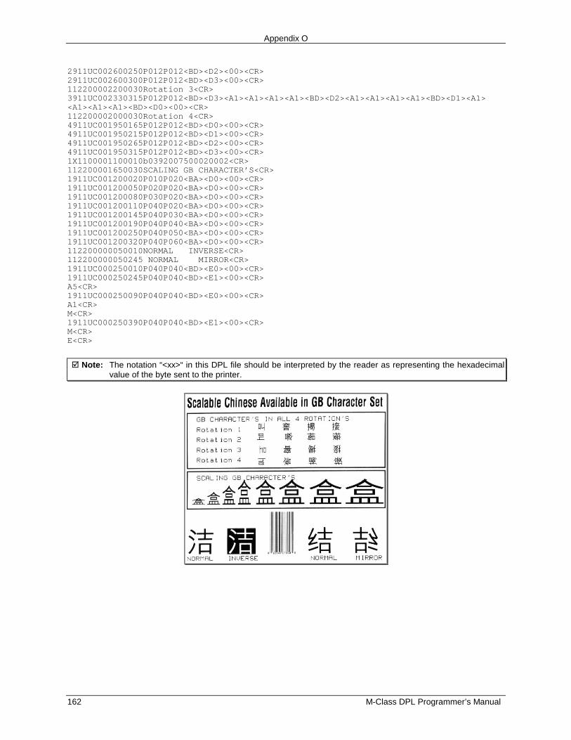
Appendix O
162 M-Class DPL Programmer’s Manual
2911UC002600250P012P012<BD><D2><00><CR>2911UC002600300P012P012<BD><D3><00><CR>112200002200030Rotation 3<CR>3911UC002330315P012P012<BD><D3><A1><A1><A1><A1><BD><D2><A1><A1><A1><A1><BD><D1><A1><A1><A1><A1><BD><D0><00><CR>112200002000030Rotation 4<CR>4911UC001950165P012P012<BD><D0><00><CR>4911UC001950215P012P012<BD><D1><00><CR>4911UC001950265P012P012<BD><D2><00><CR>4911UC001950315P012P012<BD><D3><00><CR>1X1100001100010b0392007500020002<CR>112200001650030SCALING GB CHARACTER’S<CR>1911UC001200020P010P020<BA><D0><00><CR>1911UC001200050P020P020<BA><D0><00><CR>1911UC001200080P030P020<BA><D0><00><CR>1911UC001200110P040P020<BA><D0><00><CR>1911UC001200145P040P030<BA><D0><00><CR>1911UC001200190P040P040<BA><D0><00><CR>1911UC001200250P040P050<BA><D0><00><CR>1911UC001200320P040P060<BA><D0><00><CR>112200000050010NORMAL INVERSE<CR>112200000050245 NORMAL MIRROR<CR>1911UC000250010P040P040<BD><E0><00><CR>1911UC000250245P040P040<BD><E1><00><CR>A5<CR>1911UC000250090P040P040<BD><E0><00><CR>A1<CR>M<CR>1911UC000250390P040P040<BD><E1><00><CR>M<CR>E<CR>
� Note: The notation “<xx>“ in this DPL file should be interpreted by the reader as representing the hexadecimalvalue of the byte sent to the printer.
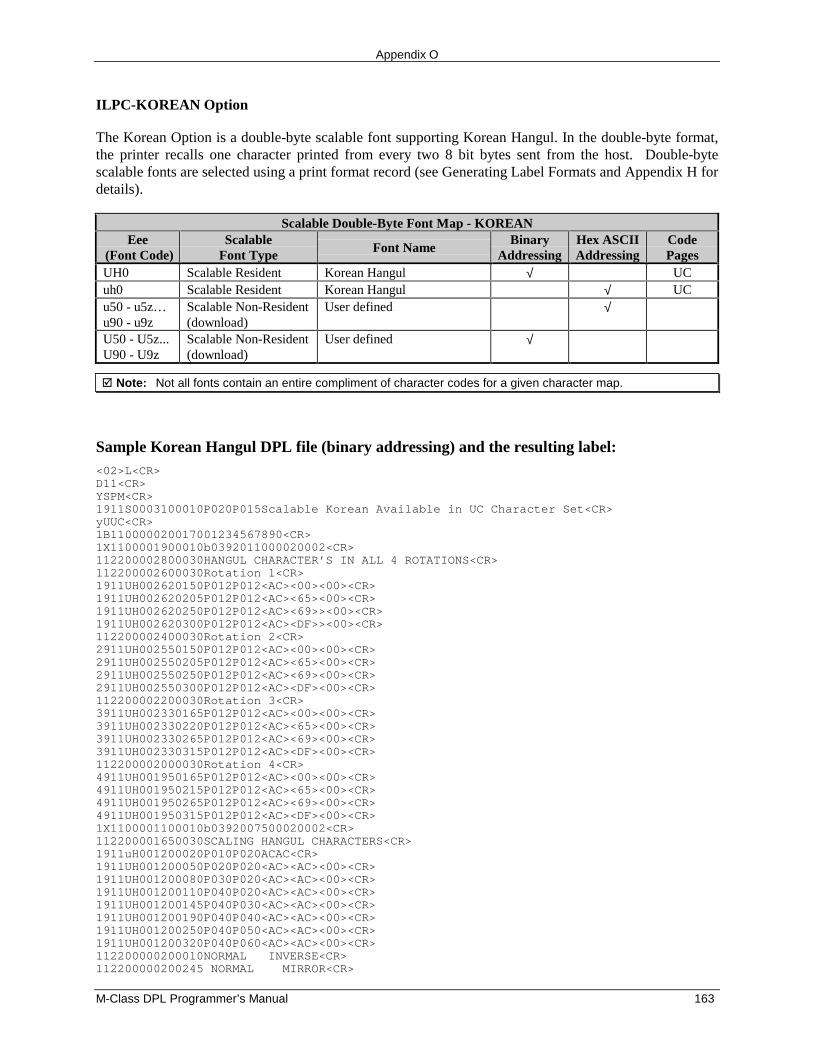
Appendix O
M-Class DPL Programmer’s Manual 163
ILPC-KOREAN Option
The Korean Option is a double-byte scalable font supporting Korean Hangul. In the double-byte format,the printer recalls one character printed from every two 8 bit bytes sent from the host. Double-bytescalable fonts are selected using a print format record (see Generating Label Formats and Appendix H fordetails).
Scalable Double-Byte Font Map - KOREANEee
(Font Code)Scalable
Font Type Font NameBinary
AddressingHex ASCIIAddressing
CodePages
UH0 Scalable Resident Korean Hangul √ UCuh0 Scalable Resident Korean Hangul √ UCu50 - u5z…u90 - u9z
Scalable Non-Resident(download)
User defined √
U50 - U5z...U90 - U9z
Scalable Non-Resident(download)
User defined √
� Note: Not all fonts contain an entire compliment of character codes for a given character map.
Sample Korean Hangul DPL file (binary addressing) and the resulting label:<02>L<CR>D11<CR>YSPM<CR>1911S0003100010P020P015Scalable Korean Available in UC Character Set<CR>yUUC<CR>1B110000020017001234567890<CR>1X1100001900010b0392011000020002<CR>112200002800030HANGUL CHARACTER’S IN ALL 4 ROTATIONS<CR>112200002600030Rotation 1<CR>1911UH002620150P012P012<AC><00><00><CR>1911UH002620205P012P012<AC><65><00><CR>1911UH002620250P012P012<AC><69>><00><CR>1911UH002620300P012P012<AC><DF>><00><CR>112200002400030Rotation 2<CR>2911UH002550150P012P012<AC><00><00><CR>2911UH002550205P012P012<AC><65><00><CR>2911UH002550250P012P012<AC><69><00><CR>2911UH002550300P012P012<AC><DF><00><CR>112200002200030Rotation 3<CR>3911UH002330165P012P012<AC><00><00><CR>3911UH002330220P012P012<AC><65><00><CR>3911UH002330265P012P012<AC><69><00><CR>3911UH002330315P012P012<AC><DF><00><CR>112200002000030Rotation 4<CR>4911UH001950165P012P012<AC><00><00><CR>4911UH001950215P012P012<AC><65><00><CR>4911UH001950265P012P012<AC><69><00><CR>4911UH001950315P012P012<AC><DF><00><CR>1X1100001100010b0392007500020002<CR>112200001650030SCALING HANGUL CHARACTERS<CR>1911uH001200020P010P020ACAC<CR>1911UH001200050P020P020<AC><AC><00><CR>1911UH001200080P030P020<AC><AC><00><CR>1911UH001200110P040P020<AC><AC><00><CR>1911UH001200145P040P030<AC><AC><00><CR>1911UH001200190P040P040<AC><AC><00><CR>1911UH001200250P040P050<AC><AC><00><CR>1911UH001200320P040P060<AC><AC><00><CR>112200000200010NORMAL INVERSE<CR>112200000200245 NORMAL MIRROR<CR>
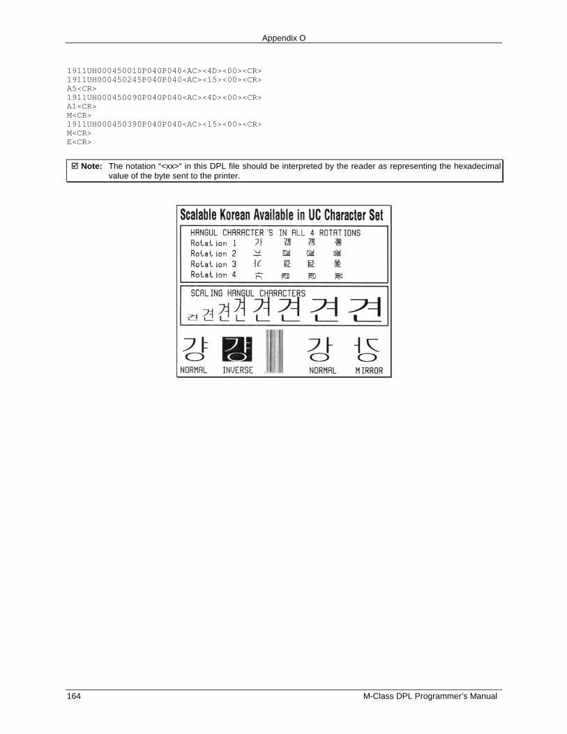
Appendix O
164 M-Class DPL Programmer’s Manual
1911UH000450010P040P040<AC><4D><00><CR>1911UH000450245P040P040<AC><15><00><CR>A5<CR>1911UH000450090P040P040<AC><4D><00><CR>A1<CR>M<CR>1911UH000450390P040P040<AC><15><00><CR>M<CR>E<CR>
� Note: The notation “<xx>“ in this DPL file should be interpreted by the reader as representing the hexadecimalvalue of the byte sent to the printer.
M-Class Programmer’s Manual 165
Appendix P
Downloading Firmware
The operating programs and fonts for the printer are stored in Flash memory on the Main PCB. Whenprogram updates and/or new features are added, they can be downloaded to the printer as follows:
1. Identify the new version for the model of your printer from the Datamax web site atwww.datamaxcorp.com and download it onto your computer’s hard drive or a floppy disk.
2. Ensure that the printer is connected to the host, (via parallel port only) and that the power is ‘On.’Using the DOS copy command enter:
copy filename.dlf lpt1/b
� Note: Other programs (e.g., hyper-terminal and certain Windows programs) may also be used todownload this file.
The READY light will flash during the download.
3. One of the two possible outcomes when attempting a download are as follows:
Following a successful download, the STOP Light will illuminate, and then the printer willperform a ‘cold reset.’ The previous printer setup will not be affected unless substantial firmwaredata structure changes have occurred. Print a Database Configuration Label to verify your newfirmware version.
Following an unsuccessful download, the ERROR Light will illuminate then the printer willperform a ‘warm reset’ (both the READY and STOP lights will be on during power-upinitialization). The original firmware will remain operational. If the printer fails to reset, toggle thepower ‘Off’ and ‘On.’
Try re-sending the file to the printer. If the failure continues, check for these possible causes:
• An invalid or corrupted file is being downloaded - Ensure the file being downloaded is correctand applicable for your printer model.
• Possible communications error - Check the cable connection between the host and printer andensure that a quality, shielded cable is used.
• Possible Flash memory problem - Call for service.
If the printer fails to boot-up after an unsuccessful download, turn ‘Off’ the power. Simultaneouslypress and hold the PAUSE + CANCEL buttons while powering ‘On’ the printer. Now, trydownloading the file to the printer.
Appendix P
166 M-Class Programmer’s Manual
M-Class Programmer’s Manual 167
Appendix Q
Bar Code Symbology Information Sources
AIM International, Inc.11860 Sunrise Valley Drive, Suite 101Reston, VA 22091 USATel: 703-391-7621Fax: 703-391-7624
AIM JAPANAios Gotanda Bldg. 6F1-10-7 HigashigotandaShinagawa-ku Tokyo 141 JapanTel: 03-3440-9085Fax: 03-3440-9086
AIM EUROPEThe Old VicarageHaley Hill, Halifax HX3 6DRWest Yorkshire, EnglandTel: 44-1422-359161Fax: 44-1422-3556904
AIM UKThe Old VicarageHaley Hill, Halifax HX3 6DRUnited KingdomTel: 44-1422-359161Fax: 44-1422-355604
AIM USA634 Alpha DrivePittsburgh, PA 15238-2802 USATel: 412-963-8588Fax: 412-963-8753
American National Standards Institute (ANSI)11 West 42nd StreetNew York, New York 10036 USATel: 212-642-4900 Fax: 212-398-0023
Appendix Q
168 M-Class Programmer’s Manual
Automotive Industry Action Group26200 Lahser RoadSuite 200Southfield, MI 48034 USATel: 313-358-3570Fax: 313-358-3253
Computing Technology Industry Association450 E. 22 Street Suite 230Lombard, IL 60148-6158 USATel: 630 268-1818Fax: 630 278-1384
Health Industry Business Communications CouncilPO Box 53528Phoenix, AZ 85018 USATel 602-318-1091
International Article Numbering Association(EAN)Rue Royal 29B-1000 BrusselsBelgiumTel: 32-22-187674Fax: 32-22-187585
Uniform Code Council, Inc. (UCC)8163 Old Yankee Rd. Suite JDayton, OH 45458 USATel: 513-435-3870Fax: 513-435-4749
U.S. Government Printing Office732 North Capitol Street NWWashington, DC 20401 USATel: 202-512-1991Fax: 202-512-1293
M-Class Programmer’s Manual 169
Glossary
alphanumeric Consisting of alphabetic, numeric, punctuation and other symbols.
backing material The silicon-coated paper carrier material to which labels with adhesive backing areaffixed. Also referred to as “liner”.
bar code A representation of alphanumeric information in a pattern of machine-readable marks. Thebasic categories are divided into one-dimensional (UPC, Code 39, Postnet, etc.) and two-dimensional barcodes (Data Matrix, MaxiCode, PDF417, etc.).
boot loader The resident program that loads the application from Flash memory, decompresses it intothe DRAM, and starts operations.
burn line The row of thermal elements in the printhead that create the images on the media.
calibration The process through which Media Sensor readings are entered into the printer for correctsensor function (for example, detection of a given media type) and top of form positioning.
character set The entire complement of alphanumeric symbols contained in a given font.
checksum An alphanumeric error detection method used in many bar code symbologies forinformational security.
continuous media An uninterrupted roll or box of label or tag stock media that contains no gap, slit,notch, or black mark to separate individual labels or tags.
cutter A mechanical device with a rotary or guillotine type blade used to cut labels or tags followingprinting.
defaults The functional setting values returned following a factory reset of the printer.
diagnostics Programs used to locate and diagnose hardware problems.
die-cut media Media that has been cut into a pattern using a press, where the excess paper is removedleaving individual labels, with gaps between them, attached to a backing material.
direct thermal The printing method that uses a heat sensitive media and only the heat of the thermalprinthead to create an image on the label.
direct thermal media Media coated with special chemicals that react and darken with the applicationof heat.
DPI (dots per inch) A measurement of print resolution, rated in the number of thermal elementscontained in one inch of the printhead. Also referred to as “resolution.”
Glossary
170 M-Class Programmer’s Manual
DPL (Datamax Programming Language) programming commands used specifically for control ofand label production in Datamax printers.
fan-fold Media that is folded and stacked.
feed speed The rate at which the media moves under the printhead in non-printed areas and betweenlabels.
Flash memory Non-volatile memory (does not require printer power to maintain data) that can beerased and reprogrammed, used to hold the printer’s operating program.
font A set of alphanumeric characters that share a particular typeface.
gap A space between die-cut or notched labels used to sense the top-of-form.
IPS (inches per second) Imperial measurement of printer speeds.
label A paper or synthetic printing material, typically with a pressure sensitive adhesive backing.
label length The distance from the top of the label to the bottom of the label as it exits the printer.
label repeat The distance from the top of one label to the top of the next label.
label tracking Excessive lateral (side to side) movement of the media as it travels under the printhead.
label width The left to right measurement of the label as it exits the printer.
media Generalized term for all types of printing stocks, including: roll fed, continuous, butt-cut, die-cut, reflective, and fanfold.
media hub Device in the printer used to support roll media.
media sensor An electronic device equipped with photosensors to detect media and the top-of-form ondie-cut, notched or reflective media.
MMPS (millimeters per second) Metric measurement of printer speeds.
notched stock Media, typically tag stock, with holes or notches in the material that is used to signal thetop-of-form. The printer must be set to ‘gap’ to use this media type.
perforation Small cuts extending through the backing and/or label material to facilitate theirseparation. Also referred to as “perf”.
preprinted media Label stock that contains borders, text, or graphics, floodcoating, etc.
present sensor An electronic sensor that provides a signal to the printer firmware that a label ispresent, typically located beyond the printhead, where the labels exits the printer.
print speed The rate at which the media moves under the printhead during the printing process.
Glossary
M-Class DPL Programmer’s Manual 171
reflective media Media imprinted with carbon-based black marks on the underside of the material,which is used to signal the top-of-form when the ‘reflective’ Media Sensor is enabled.
registration Repeatable top to bottom alignment of printed labels. reverse speed The backward rate of media motion into the printer during tear-off, peel and present and
cutting operations for positioning the label at the start of print position.
ribbon An extruded polyester tape with several layers of material, one of which is ink-like, used toproduce an image on the label. Also referred to as “foil”.
roll media A form of media that is wound upon a cardboard core.
start of print The position on the label where the printing actually begins.
tag stock A heavy paper or synthetic printing material, typically featuring a notch or black mark for topof form and no adhesive backing.
thermal transfer The printing method that creates an image by transferring ink from a ribbon onto themedia using the heat from the thermal printhead.
TOF (top-of-form) The start of a new label as indicated by a label gap, notch, mark or programming.


![[4] - DPL Homes](https://img.pdfslide.us/doc/110x75/6178ed8e7b08394ecd4e312d/4-dpl-homes.jpg)