Embed Size (px)
Citation preview

Service Manual
Part No. 40462
Rev A6
September 2016
DPL-25SDPL-30SDPL-35SSuper Series
Serial Number Range
from 1596-101to 1501-915
from DPL02-916to DPL16-2311
from DPL16G-2312to DPL16G-2599
from DPLG-2600
DPL-25S • DPL-30S • DPL-35S Super Series Part No. 40462
September 2016
ii
Copyright © 2011 Terex Corporation
First Edition, First Printing, August 1996
Genie is a registered trademark of Terex SouthDakota, Inc in the USA and many othercountries.
Printed on recycled paper
Printed in U.S.A.
Important
Read, understand and obey the safety rules andoperating instructions in the appropriate operator'smanual on your machine before attempting anymaintenance or repair procedure.
This manual provides detailed scheduledmaintenance information for the machine owner anduser. It also provides troubleshooting and repairprocedures for qualified service professionals.
Basic mechanical, hydraulic and electrical skills arerequired to perform most procedures. However,several procedures require specialized skills, tools,lifting equipment and a suitable workshop. In theseinstances, we strongly recommend thatmaintenance and repair be performed at anauthorized Genie dealer service center.
Compliance
Machine ClassificationGroup A/Type 1 as defined by ISO 16368
Machine Design LifeUnrestricted with proper opeation, inspection andscheduled maintenance.
Technical Publications
Genie has endeavored to deliver the highest degreeof accuracy possible. However, continuousimprovement of our products is a Genie policy.Therefore, product specifications are subject tochange without notice.
Readers are encouraged to notify Genie of errorsand send in suggestions for improvement. Allcommunications will be carefully considered forfuture printings of this and all other manuals.
Contact Us:http://www.genlift.come-mail: [email protected]
Introduction

Part No. 40462 DPL-25S • DPL-30S • DPL-35S Super Series
September 2016
Serial Number Legend
Model: Serial number:
Model year:
Elec/Hydr Schematic:
Manufacture date:
Power supply voltage/Pneumatic Pressure:
Maximum Wind Speed:
Maximum allowable inclination of the chassis:
Gradeability:
Maximum platform height:Maximum allowable side force:
Machine unladen weight:Max Load:Occupants and Equipment must not exceed:
Indoor:Outdoor:
Nominal Power:
DPL16G-1234
201601/02/2010
DPL 16 G - 1234
21 43
6
5
Model:
Elec/Hydr Schematic:
Year of Manufacture :
Power supply voltage/Pneumatic Pressure:
Maximum Wind Speed:
Maximum allowable inclination of the chassis:
Gradeability:
Maximum platform height:Maximum allowable side force:
Machine unladen weight:Max Load:Occupants and Equipment must not exceed:
Indoor:Outdoor:
Nominal Power:
2016
DPL G - 1234
21 3Serial number: DPLG-1234
5
4
1 Model2 Facility code3 Sequence number
4 Serial number (stamped on chassis)5 Serial label
From September 1, 2016
1 Model2 Model year3 Facility code
4 Sequence number5 Serial number (stamped on chassis)6 Serial label
To August 31, 2016
iii
DPL-25S • DPL-30S • DPL-35S Super Series Part No. 40462
September 2016
iv
Section 1 - Safety Rules
Safety Rules
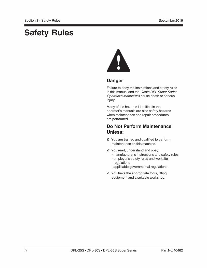
DangerFailure to obey the instructions and safety rulesin this manual and the Genie DPL Super SeriesOperator's Manual will cause death or seriousinjury.
Many of the hazards identified in theoperator’s manuals are also safety hazardswhen maintenance and repair proceduresare performed.
Do Not Perform MaintenanceUnless:
You are trained and qualified to perform
maintenance on this machine.
You read, understand and obey:
- manufacturer’s instructions and safety rules- employer’s safety rules and worksite
regulations- applicable governmental regulations
You have the appropriate tools, lifting
equipment and a suitable workshop.
Part No. 40462 DPL-25S • DPL-30S • DPL-35S Super Series
September 2016 Section 1 - Safety Rules
v
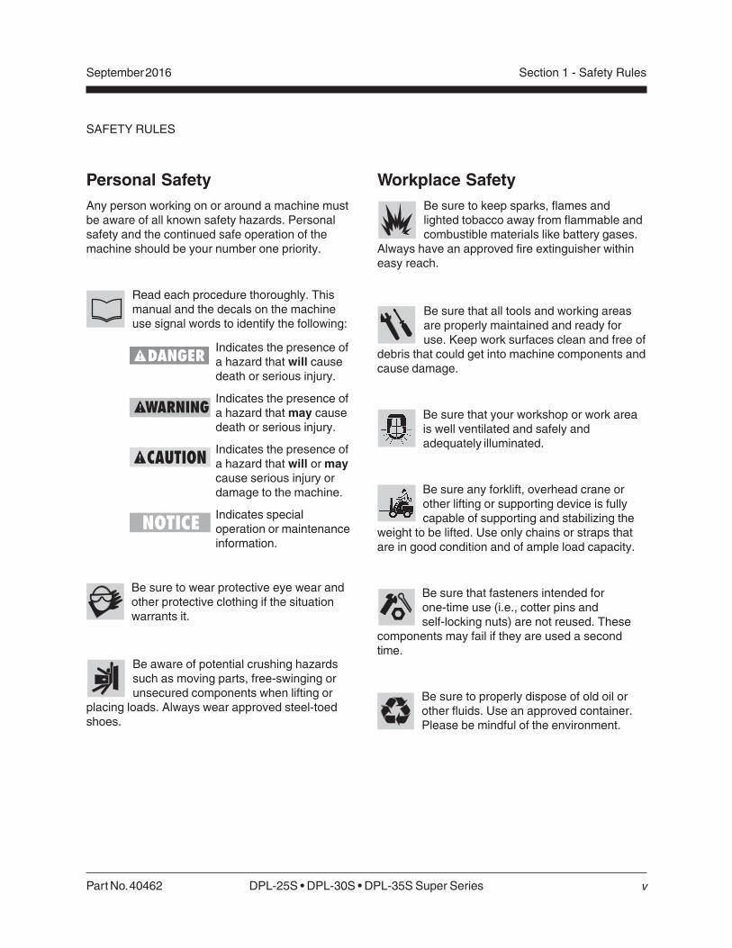
Workplace SafetyBe sure to keep sparks, flames andlighted tobacco away from flammable andcombustible materials like battery gases.
Always have an approved fire extinguisher withineasy reach.
Be sure that all tools and working areasare properly maintained and ready foruse. Keep work surfaces clean and free of
debris that could get into machine components andcause damage.
Be sure that your workshop or work areais well ventilated and safely andadequately illuminated.
Be sure any forklift, overhead crane orother lifting or supporting device is fullycapable of supporting and stabilizing the
weight to be lifted. Use only chains or straps thatare in good condition and of ample load capacity.
Be sure that fasteners intended forone-time use (i.e., cotter pins andself-locking nuts) are not reused. These
components may fail if they are used a secondtime.
Be sure to properly dispose of old oil orother fluids. Use an approved container.Please be mindful of the environment.
Personal SafetyAny person working on or around a machine mustbe aware of all known safety hazards. Personalsafety and the continued safe operation of themachine should be your number one priority.
Read each procedure thoroughly. Thismanual and the decals on the machineuse signal words to identify the following:
Indicates the presence ofa hazard that will causedeath or serious injury.
Indicates the presence ofa hazard that may causedeath or serious injury.
Indicates the presence ofa hazard that will or maycause serious injury ordamage to the machine.
Indicates specialoperation or maintenanceinformation.
Be sure to wear protective eye wear andother protective clothing if the situationwarrants it.
Be aware of potential crushing hazardssuch as moving parts, free-swinging orunsecured components when lifting or
placing loads. Always wear approved steel-toedshoes.
SAFETY RULES
DPL-25S • DPL-30S • DPL-35S Super Series Part No. 40462
September 2016
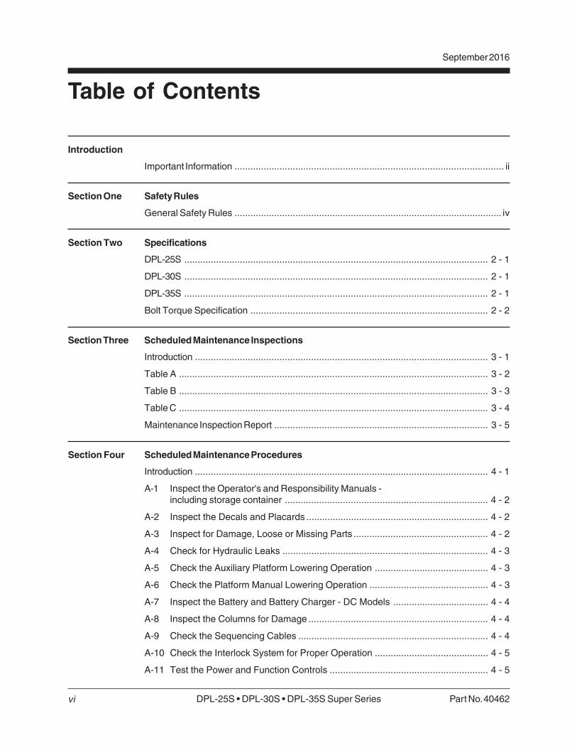
Table of Contents
Introduction
Important Information ...................................................................................................... ii
Section One Safety Rules
General Safety Rules ..................................................................................................... iv
Section Two Specifications
DPL-25S ................................................................................................................... 2 - 1
DPL-30S ................................................................................................................... 2 - 1
DPL-35S ................................................................................................................... 2 - 1
Bolt Torque Specification .......................................................................................... 2 - 2
Section Three Scheduled Maintenance Inspections
Introduction ............................................................................................................... 3 - 1
Table A ..................................................................................................................... 3 - 2
Table B ..................................................................................................................... 3 - 3
Table C ..................................................................................................................... 3 - 4
Maintenance Inspection Report ................................................................................. 3 - 5
Section Four Scheduled Maintenance Procedures
Introduction ............................................................................................................... 4 - 1
A-1 Inspect the Operator's and Responsibility Manuals -including storage container ............................................................................. 4 - 2
A-2 Inspect the Decals and Placards ..................................................................... 4 - 2
A-3 Inspect for Damage, Loose or Missing Parts ................................................... 4 - 2
A-4 Check for Hydraulic Leaks .............................................................................. 4 - 3
A-5 Check the Auxiliary Platform Lowering Operation ........................................... 4 - 3
A-6 Check the Platform Manual Lowering Operation ............................................. 4 - 3
A-7 Inspect the Battery and Battery Charger - DC Models .................................... 4 - 4
A-8 Inspect the Columns for Damage .................................................................... 4 - 4
A-9 Check the Sequencing Cables ........................................................................ 4 - 4
A-10 Check the Interlock System for Proper Operation ........................................... 4 - 5
A-11 Test the Power and Function Controls ............................................................ 4 - 5
vi
Part No. 40462 DPL-25S • DPL-30S • DPL-35S Super Series
September 2016
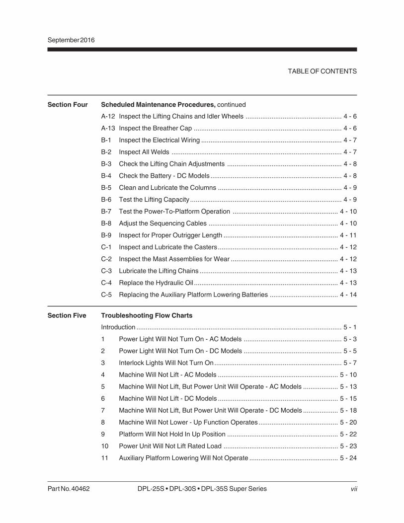
Section Four Scheduled Maintenance Procedures, continued
A-12 Inspect the Lifting Chains and Idler Wheels .................................................... 4 - 6
A-13 Inspect the Breather Cap ................................................................................ 4 - 6
B-1 Inspect the Electrical Wiring ............................................................................ 4 - 7
B-2 Inspect All Welds ............................................................................................ 4 - 7
B-3 Check the Lifting Chain Adjustments .............................................................. 4 - 8
B-4 Check the Battery - DC Models ....................................................................... 4 - 8
B-5 Clean and Lubricate the Columns ................................................................... 4 - 9
B-6 Test the Lifting Capacity .................................................................................. 4 - 9
B-7 Test the Power-To-Platform Operation ......................................................... 4 - 10
B-8 Adjust the Sequencing Cables ...................................................................... 4 - 10
B-9 Inspect for Proper Outrigger Length .............................................................. 4 - 11
C-1 Inspect and Lubricate the Casters................................................................. 4 - 12
C-2 Inspect the Mast Assemblies for Wear .......................................................... 4 - 12
C-3 Lubricate the Lifting Chains ........................................................................... 4 - 13
C-4 Replace the Hydraulic Oil .............................................................................. 4 - 13
C-5 Replacing the Auxiliary Platform Lowering Batteries ..................................... 4 - 14
Section Five Troubleshooting Flow Charts
Introduction ............................................................................................................... 5 - 1
1 Power Light Will Not Turn On - AC Models ..................................................... 5 - 3
2 Power Light Will Not Turn On - DC Models ..................................................... 5 - 5
3 Interlock Lights Will Not Turn On..................................................................... 5 - 7
4 Machine Will Not Lift - AC Models ................................................................. 5 - 10
5 Machine Will Not Lift, But Power Unit Will Operate - AC Models ................... 5 - 13
6 Machine Will Not Lift - DC Models ................................................................. 5 - 15
7 Machine Will Not Lift, But Power Unit Will Operate - DC Models ................... 5 - 18
8 Machine Will Not Lower - Up Function Operates ........................................... 5 - 20
9 Platform Will Not Hold In Up Position ............................................................ 5 - 22
10 Power Unit Will Not Lift Rated Load .............................................................. 5 - 23
11 Auxiliary Platform Lowering Will Not Operate ................................................ 5 - 24
TABLE OF CONTENTS
vii

DPL-25S • DPL-30S • DPL-35S Super Series Part No. 40462
September 2016
TABLE OF CONTENTS
viii
Section Six Schematics
Introduction ............................................................................................................... 6 - 1
Electrical Legend ...................................................................................................... 6 - 2
Hydraulic Legend ...................................................................................................... 6 - 3
Electrical Schematic - DPL Super Series DC - All Models(before serial number DPL07-1499) ......................................................................... 6 - 5
Electrical Schematic - DPL Super Series DC - ANSI Models(after serial number DPL07-1498) ............................................................................ 6 - 6
Electrical Schematic - DPL Super Series DC - CE Models(after serial number DPL07-1498) ............................................................................ 6 - 7
Electrical Schematic - DPL Super Series AC - All Models(before serial number DPL07-1499) ......................................................................... 6 - 8
Electrical Schematic - DPL Super Series AC - ANSI Models(from serial number DPL07-1499 to DPL07-1562) .................................................... 6 - 9
Electrical Schematic - DPL Super Series AC - ANSI Models(after serial number DPL07-1562) .......................................................................... 6 - 10
Electrical Schematic - DPL Super Series AC - CE Models(from serial number DPL07-1499 to DPL07-1562) .................................................. 6 - 11
Electrical Schematic - DPL Super Series AC - CE Models(after serial number DPL07-1562) .......................................................................... 6 - 12
Hydraulic Schematic - ANSI ................................................................................... 6 - 13
Hydraulic Schematic - CE ....................................................................................... 6 - 14
Part No. 40462 DPL-25S • DPL-30S • DPL-35S Super Series
September 2016
ix
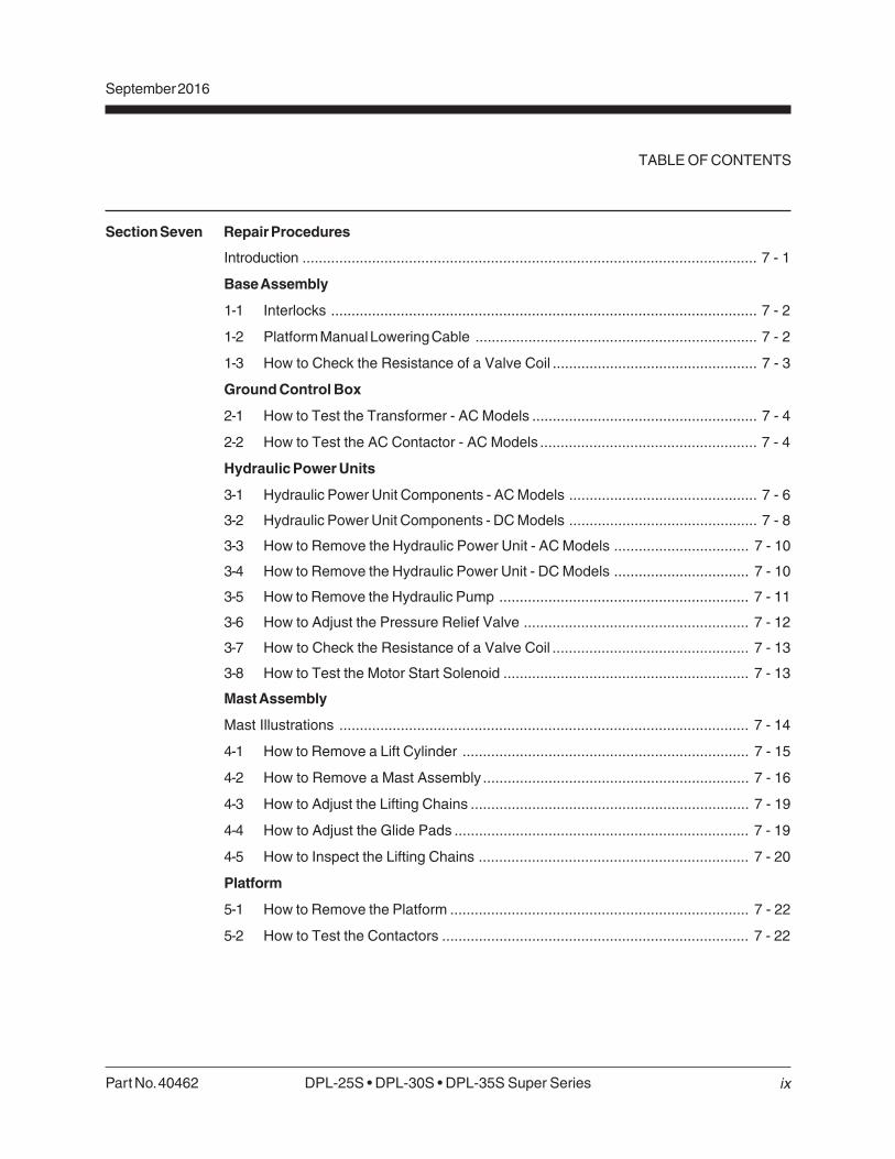
Section Seven Repair Procedures
Introduction ............................................................................................................... 7 - 1
Base Assembly
1-1 Interlocks ........................................................................................................ 7 - 2
1-2 Platform Manual Lowering Cable ..................................................................... 7 - 2
1-3 How to Check the Resistance of a Valve Coil .................................................. 7 - 3
Ground Control Box
2-1 How to Test the Transformer - AC Models ....................................................... 7 - 4
2-2 How to Test the AC Contactor - AC Models ..................................................... 7 - 4
Hydraulic Power Units
3-1 Hydraulic Power Unit Components - AC Models .............................................. 7 - 6
3-2 Hydraulic Power Unit Components - DC Models .............................................. 7 - 8
3-3 How to Remove the Hydraulic Power Unit - AC Models ................................. 7 - 10
3-4 How to Remove the Hydraulic Power Unit - DC Models ................................. 7 - 10
3-5 How to Remove the Hydraulic Pump ............................................................. 7 - 11
3-6 How to Adjust the Pressure Relief Valve ....................................................... 7 - 12
3-7 How to Check the Resistance of a Valve Coil ................................................ 7 - 13
3-8 How to Test the Motor Start Solenoid ............................................................ 7 - 13
Mast Assembly
Mast Illustrations .................................................................................................... 7 - 14
4-1 How to Remove a Lift Cylinder ...................................................................... 7 - 15
4-2 How to Remove a Mast Assembly ................................................................. 7 - 16
4-3 How to Adjust the Lifting Chains .................................................................... 7 - 19
4-4 How to Adjust the Glide Pads ........................................................................ 7 - 19
4-5 How to Inspect the Lifting Chains .................................................................. 7 - 20
Platform
5-1 How to Remove the Platform ......................................................................... 7 - 22
5-2 How to Test the Contactors ........................................................................... 7 - 22
TABLE OF CONTENTS

Part No. 40462 DPL25S • DPL-30S • DPL-35S Super Series 2 - 1
Section 2 - SpecificationsSeptember 2016
Specifications
Model DPL-25S DPL-30S DPL-35S
Height, 31 ft 4 in 36 ft 40 ft 9 in
maximum working 9.5 m 11 m 12.4 m
Height, 25 ft 4 in 30 ft 34 ft 9 in
maximum platform 7.7 m 9.2 m 10.6 m
Height, 78 in 78 in 78 in
guard rails stowed 197.8 cm 197.8 cm 197.8 cm
Length, 813/4 in 813/4 in 813/4 in
outriggers stowed 207.6 cm 207.6 cm 207.6 cm
Width, 311/2 in 311/2 in 311/2 in
outriggers stowed 80 cm 80 cm 80 cm
Outrigger footprint 82 x 561/2 in 861/4 x 673/4 in 861/4 x 673/4 in
(l x w) 208.3 x 143.5 cm 218.7 x 172.1 cm 218.7 x 172.1 cm
Platform dimensions 72 x 271/2 in 72 x 271/2 in 72 x 271/2 in
(l x w) 182.9 x 69.9 cm 182.9 x 69.9 cm 182.9 x 69.9 cm
Lift capacity 750 lbs 750 lbs 600 lbs
340 kg 340 kg 272 kg
Power source 12V DC or 12V DC or 12V DC or
220V or 115V AC 220V or 115V AC 220V or 115V AC
Shipping weight 1375 / 1450 lbs 1475 / 1550 lbs 1575 / 1650 lbs
(AC / DC) 624 / 658 kg 669 / 703 kg 714 / 748 kg
Maximum capacity
ANSI 750 lbs / 340 kg 750 lbs / 340 kg 600 lbs / 272 kg
CE 750 lbs / 340 kg 750 lbs / 340 kg 600 lbs / 272 kg
CSA 600 lbs / 272 kg 600 lbs / 272 kg 500 lbs / 227 kg
Ambient operating -20°F to 135°F
temperature -29°C to 57°C
Airborne noise emissions 80 dB
Maximum sound level at normal operating workstations
(A-weighted)
Current Protection Rating
220V AC models 8A fuse, circuit breaker
5A fuse, printed circuit board
110V AC models 15A fuse, circuit breaker
5A fuse, printed circuit board
DC models 175A fuse, power unit
5A fuse, printed circuit board

2 - 2 DPL-25S • DPL-30S • DPL35S Super Series Part No. 40462
Section 2 - Specifications September 2016
Torque - Dry
inch-pounds
Torque - Dry
foot-pounds
Torque - Dry
Newton meters
Torque - Dry
inch-pounds
Torque - Dry
foot-pounds
Torque - Dry
Newton meters
43
49
96
120
17
19
30
35
50
55
75
90
110
120
150
170
260
300
430
470
640
700
5
6
11
14
23
28
41
48
68
75
102
122
149
163
204
231
353
407
583
637
868
949
60
68
144
168
25
25
45
50
70
80
110
120
150
170
220
240
380
420
600
660
900
1000
7
8
16
19
34
34
61
68
95
109
149
163
204
231
298
326
515
570
814
895
1221
1356
Torque specifications for lubricated bolts are 25% less than the dry torque specifications for each bolt size.
These bolt torque specifications are for general use only. Specification may vary depending on application of bolt.
Size Threads SAE Grade 5 Bolts SAE Grade 8 Bolts per inch
Bolt Torque Specifications
24
32
20
28
18
24
16
24
14
20
13
20
12
18
11
18
10
16
9
14
8
12
10
1/4
5/16
3/8
7/16
1/2
9/16
5/8
3/4
7/8
1
SPECIFICATIONS

Part No. 40462 DPL-25S • DPL-30S • DPL-35S Super Series 3 - 1
Section 3 - Scheduled Maintenance InspectionsSeptember 2016
Dealer
service
suggested
Tools are
required
New parts
required
Scheduled Maintenance Inspections
Observe and Obey:
Maintenance inspections shall be completed by
a person trained and qualified on themaintenance of this machine.
Scheduled maintenance inspections shall be
completed daily, quarterly and annually asspecified on the Maintenance InspectionReport.
Failure to properly complete eachinspection when required mayresult in death, serious injury orsubstantial machine damage.
Immediately tag and remove from service a
damaged or malfunctioning machine.
Repair any machine damage or malfunction
before operating machine.
Machines that have been out of service for aperiod longer than 3 months must have aquarterly inspection.
About This SectionSchedule
There are three types of maintenance inspectionsthat must be performed according to a schedule—daily, quarterly and annual. To account forrepeated procedures, the Maintenance Tables andthe Maintenance Inspection Report have beendivided into three subsections—A, B and C. Usethe following chart to determine which group(s) ofprocedures are required to perform a scheduledinspection.
Inspection Table or Checklist
Daily A
Quarterly (every 150 hours or three months) A + B
Annual A + B + C
Maintenance Tables
The maintenance tables contained in this sectionprovide summary information on the specificphysical requirements for each inspection.
Complete step-by-step instructions for eachscheduled maintenance procedure are provided insection 4, Scheduled Maintenance Procedures.
Maintenance Inspection Report
The Maintenance Inspection Report containschecklists for each type of scheduled inspection.
Make copies of the Maintenance Inspection Reportto use for each inspection. Maintain completedforms for a minimum of 4 years or in compliancewith your employer, jobsite and governmentalregulations and requirements.
3 - 2 DPL-25S 30S • DPL-35S Super Series Part No. 40462
Section 3 - Scheduled Maintenance Inspections September 2016
Dealer
service
suggested
Tools are
required
New parts
required
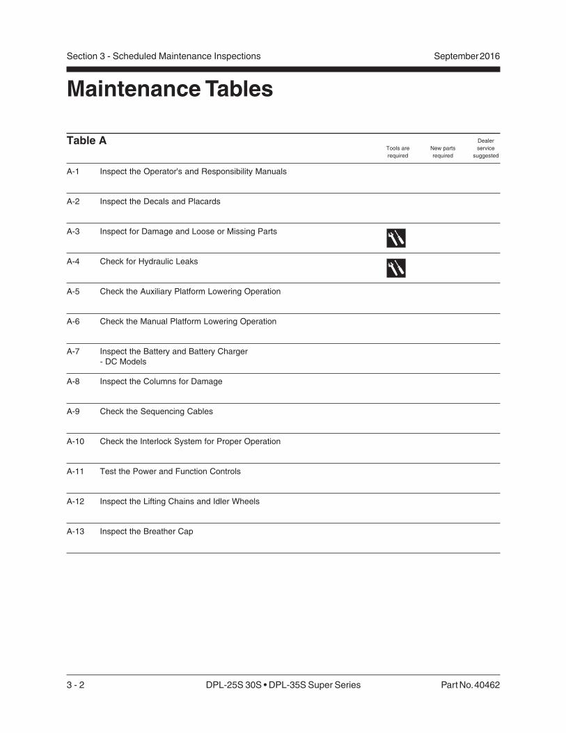
Table A
A-1 Inspect the Operator's and Responsibility Manuals
A-2 Inspect the Decals and Placards
A-3 Inspect for Damage and Loose or Missing Parts
A-4 Check for Hydraulic Leaks
A-5 Check the Auxiliary Platform Lowering Operation
A-6 Check the Manual Platform Lowering Operation
A-7 Inspect the Battery and Battery Charger
- DC Models
A-8 Inspect the Columns for Damage
A-9 Check the Sequencing Cables
A-10 Check the Interlock System for Proper Operation
A-11 Test the Power and Function Controls
A-12 Inspect the Lifting Chains and Idler Wheels
A-13 Inspect the Breather Cap
Maintenance Tables
Part No. 40462 DPL-25S • DPL-30S • DPL-35S Super Series 3 - 3
Section 3 - Scheduled Maintenance InspectionsSeptember 2016
Dealer
service
suggested
Tools are
required
New parts
required
MAINTENANCE TABLES
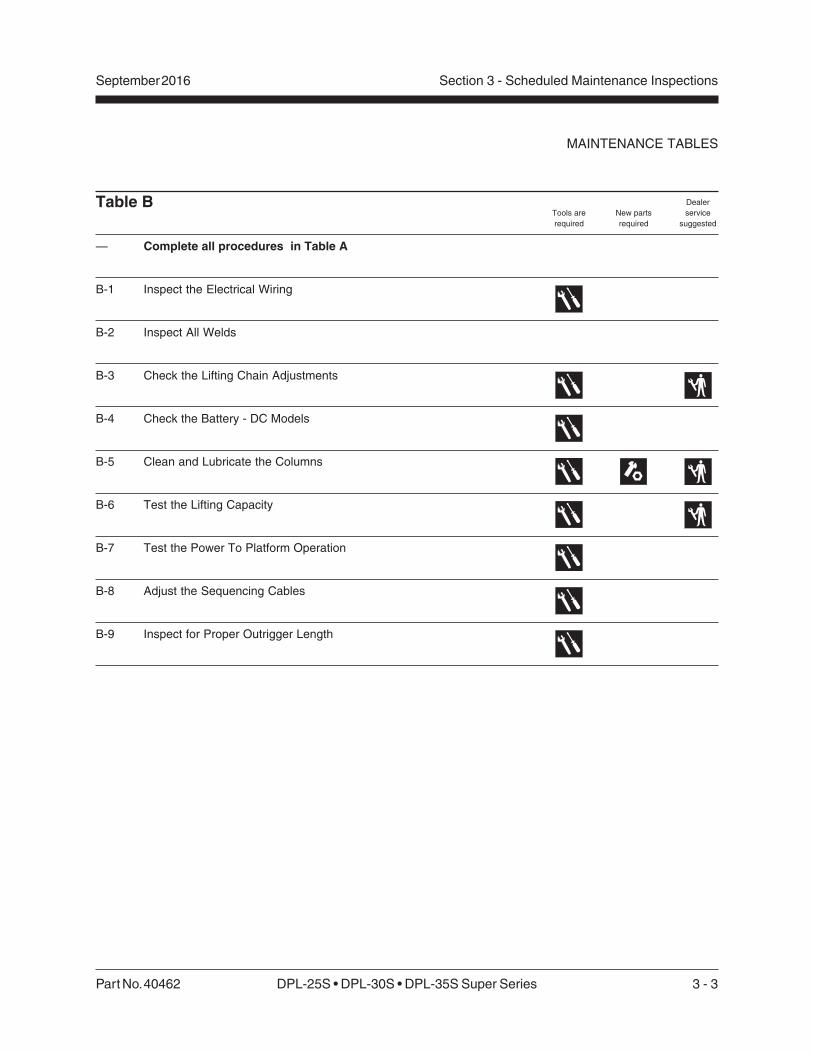
Table B
— Complete all procedures in Table A
B-1 Inspect the Electrical Wiring
B-2 Inspect All Welds
B-3 Check the Lifting Chain Adjustments
B-4 Check the Battery - DC Models
B-5 Clean and Lubricate the Columns
B-6 Test the Lifting Capacity
B-7 Test the Power To Platform Operation
B-8 Adjust the Sequencing Cables
B-9 Inspect for Proper Outrigger Length

3 - 4 DPL-25S 30S • DPL-35S Super Series Part No. 40462
Section 3 - Scheduled Maintenance Inspections September 2016
Dealer
service
suggested
Tools are
required
New parts
required
Table C
— Complete all procedures in Table A and Table B
C-1 Inspect and Lubricate the Casters and Wheels
C-2 Inspect the Mast Assembly for Wear
C-3 Lubricate the Lifting Chains
C-4 Replace the Hydraulic Oil
C-5 Replace the Auxiliary Platform Lowering Batteries
MAINTENANCE TABLES
Part No. 40462 DPL-25S • DPL-30S • DPL-35S Super Series 3 - 5
Section 3 - Scheduled Maintenance InspectionsSeptember 2016
Dealer
service
suggested
Tools are
required
New parts
required
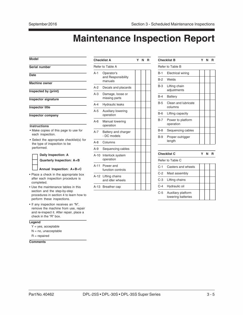
Checklist B Y N R
Refer to Table B
B-1 Electrical wiring
B-2 Welds
B-3 Lifting chain
adjustments
B-4 Battery
B-5 Clean and lubricate
columns
B-6 Lifting capacity
B-7 Power to platform
operation
B-8 Sequencing cables
B-9 Proper outrigger
length
Checklist C Y N R
Refer to Table C
C-1 Casters and wheels
C-2 Mast assembly
C-3 Lifting chains
C-4 Hydraulic oil
C-5 Auxiliary platform
lowering batteries
Checklist A Y N R
Refer to Table A
A-1 Operator's
and Responsibility
manuals
A-2 Decals and placards
A-3 Damage, loose or
missing parts
A-4 Hydraulic leaks
A-5 Auxiliary lowering
operation
A-6 Manual lowering
operation
A-7 Battery and charger
- DC models
A-8 Columns
A-9 Sequencing cables
A-10 Interlock system
operation
A-11 Power and
function controls
A-12 Lifting chains
and idler wheels
A-13 Breather cap
Maintenance Inspection Report
Model
Serial number
Date
Machine owner
Inspected by (print)
Inspector signature
Inspector title
Inspector company
Instructions• Make copies of this page to use for
each inspection.
• Select the appropriate checklist(s) for
the type of inspection to be
performed.
Daily Inspection: A
Quarterly Inspection: A+B
Annual Inspection: A+B+C
• Place a check in the appropriate box
after each inspection procedure is
completed.
• Use the maintenance tables in this
section and the step-by-step
procedures in section 4 to learn how to
perform these inspections.
• If any inspection receives an “N”,
remove the machine from use, repair
and re-inspect it. After repair, place a
check in the “R” box.
LegendY = yes, acceptable
N = no, unacceptable
R = repaired
Comments
3 - 6 DPL-25S 30S • DPL-35S Super Series Part No. 40462
Section 3 - Scheduled Maintenance Inspections September 2016
Dealer
service
suggested
Tools are
required
New parts
required
This page intentionally left blank.
Part No. 40462 DPL-25S • DPL-30S • DPL-35S Super Series 4 - 1
September 2016 Section 4 - Scheduled Maintenance Procedures
About This Section
This section contains detailed procedures for eachscheduled maintenance inspection.
Each procedure includes a description, safetywarnings and step-by-step instructions.
Symbols Legend
Indicates the presence of a hazardthat will cause death or seriousinjury.
Indicates the presence of a hazardthat may cause death or seriousinjury.
Indicates the presence of a hazardthat will or may cause seriousinjury or damage to the machine.
Indicates special operation ormaintenance information.
Indicates that a specific result is expected afterperforming a series of steps.
Observe and Obey:
Maintenance inspections shall be completed bya person trained and qualified on themaintenance of these machines.
Scheduled maintenance inspections shall becompleted daily, frequently (every 3 months),and annually as specified on the maintenancereport.
Failure to properly complete eachinspection when required mayresult in death, serious injury orsubstantial machine damage.
Immediately tag and remove from service adamaged or malfunctioning machine.
Repair any machine damage or malfunctionbefore operating machine.
Keep records on all inspections for three years.
Scheduled Maintenance Procedures

4 - 2 DPL-25S • DPL-30S • DPL-35S Super Series Part No. 40462
September 2016Section 4 - Scheduled Maintenance Procedures
A-1Inspect the Operator’s andResponsibility Manuals
Maintaining the operator’s and responsibilitymanuals in good condition is essential to safemachine operation. Manuals are included witheach machine and should be stored in thecontainer provided at the platform. An illegible ormissing manual will not provide safety andoperational information necessary for a safeoperating condition.
1 Check to be sure the storage container and lidare present and in good condition.
2 Check to make sure that the operator’s andresponsibility manuals are present andcomplete in the storage container at theplatform.
3 Examine the pages of each manual to be surethat they are legible and in good condition.
4 Always return the manuals to the storagecontainer after use.
Note: Contact your authorized Genie distributor orGenie if replacement manuals are needed.
A-2Inspect the Decals and Placards
Maintaining all of the safety and instructionaldecals and placards in good condition is essentialfor safe machine operation. Decals alert operatorsand personnel to the many possible hazardsassociated with using a machine. They alsoprovide users with operation and maintenanceinformation. An illegible decal will fail to alertpersonnel of a procedure or hazard and couldresult in unsafe operating conditions.
Table A Procedures
1 Refer to the Decals section in the Genie DPLSuper Series Operator's Manual and use thedecal list and illustrations to determine that alldecals and placards are in place.
2 Inspect all decals for legibility and damage.Replace any damaged or illegible decalimmediately.
Note: Contact your authorized Genie distributor orGenie if replacement decals are needed.
A-3Inspect for Damage and Loose orMissing Parts
Daily machine condition inspections are essentialto safe machine operation and good machineperformance. Failure to locate and repair damage,and discover loose or missing parts may result inan unsafe operating condition.
1 Inspect the entire machine for damage andimproperly installed or missing parts including:
• Electrical components and wiring
• Coil cord (if equipped)
• Hydraulic power unit, hoses, fittings andcylinders
• Manual lowering lever and components
• Platform end guard rail, platform side guardrails and platform entry gate
• Guard rail lock handles
• Sequencing cables and pulleys
• Lifting chains and idler wheels
• Nuts, bolts and other fasteners
• Mast and mast braces
• Breather cap
• Outriggers, leveling jacks and footpads
• Guard rail lift arm
• Platform entry ladder
• Dents or damage to machine
• Corrosion or oxidation
• Cracks in welds or structural components
Part No. 40462 DPL-25S • DPL-30S • DPL-35S Super Series 4 - 3
September 2016 Section 4 - Scheduled Maintenance Procedures
TABLE A PROCEDURES
A-4Check for Hydraulic Leaks
Detecting hydraulic fluid leaks is essential tooperational safety and good machine performance.Undiscovered leaks can develop into hazardousconditions, impair machine functions and damagemachine components.
1 Inspect for hydraulic oil puddles, dripping orresidue on or around the following areas:
• Hydraulic power unit—reservoir, valves,fittings
• Hydraulic cylinders
• Ground area under the machine
• All hydraulic hoses and fittings
A-5Check the Auxiliary PlatformLowering Operation
The auxiliary platform lowering is powered by asecondary battery pack that is located in theground control box. The auxiliary platform loweringcan be activated from the ground or platformcontrols. Detection of an auxiliary loweringmalfunction is essential for safe machineoperation. An unsafe working condition exists if theauxiliary platform lowering function does notoperate in the event of a main power failure.
1 Raise the platform slightly.
2 Disconnect the power source from the machine.
3 Activate the auxiliary platform lowering button atthe ground controls.
Result: Platform should lower.
4 Reconnect the power and raise the platformslightly.
5 Disconnect the power source from the machine.
6 Push in the control activate button and rotatethe up/down switch in the down direction.
Result: Platform should lower.
A-6Check the Platform ManualLowering Operation
Detection of a platform manual loweringmalfunction is essential for safe machineoperation. An unsafe working condition exists if themanual lowering function does not operate in theevent of a main and auxiliary power failure.
1 Raise the platform slightly.
2 Activate the manual lowering lever.
Result: Platform should lower.

4 - 4 DPL-25S • DPL-30S • DPL-35S Super Series Part No. 40462
September 2016Section 4 - Scheduled Maintenance Procedures
TABLE A PROCEDURES
A-7Inspect the Battery and BatteryCharger - DC Models
Proper battery and charger condition is essential togood machine performance and operational safety.Improper fluid levels or damaged cables andconnections can result in component damage andhazardous conditions.
Batteries contain acid. Avoidspilling or contacting battery acid.Neutralize battery acid spills withbaking soda and water.
1 Put on protective clothing and eye wear.
2 Slide open the battery cover to access thecharger and the battery. The cover must remainopen for the entire charging cycle.
3 Be sure that the battery cable connections aretight and free of corrosion.
4 Check the battery acid level. If needed,replenish with distilled water to the bottom ofthe battery fill tube. Do not overfill.
5 Install the vent caps.
6 Connect the battery charger to a groundedoutlet of proper voltage and amperage asindicated on battery charger.
7 Set timer based on the amount of use:
Light Use—less than 15 lifting cycles: Set to 7hours.
Heavy Use—greater than 15 lifting cycles: Setto the ON position.
8 The charger will automatically shut off at theend of the set period.
Note: If ammeter drops to 3A or less within the first15 minutes, the battery is fully charged.
9 Check the battery acid level when the chargecycle is complete. Replenish with distilledwater to the bottom of the fill tube.
A-8Inspect the Columns for Damage
Detection of damage to columns is essential forsafe machine operation. An unsafe workingcondition exists if the columns are damaged anddo not operate smoothly, free of hesitation andbinding. A daily check of the columns allows theinspector to identify changes in the operatingcondition of the column assemblies that mightindicate damage.
1 Visually inspect each column on each mast forthe following:
• Dents, gouges or abrasions
• Bends or warping
• Excessive wear
2 Raise and lower the platform through a completecycle.
Result: Platform should raise and lowersmoothly, free of hesitation and binding.
A-9Check the Sequencing Cables
Detection of damage to sequencing cables orcomponents is essential for safe machineoperation. An unsafe working condition exists if thesequencing components are damaged and do notoperate smoothly. A daily check of the sequencingsystem allows the inspector to identify changes inthe operating condition that might indicate damage.
Part No. 40462 DPL-25S • DPL-30S • DPL-35S Super Series 4 - 5
September 2016 Section 4 - Scheduled Maintenance Procedures
TABLE A PROCEDURES
1 Visually inspect the cables and components forthe following:
• Frayed or broken wire strands
• Kinks in the cables
• Corrosion
• Paint or foreign materials
• Broken or damaged pulleys
• Unusual or excessive pulley wear
• Split or cracked swage ends
• Split or cracked chain adjustment bolts
• Bent or damaged pulley guards
2 Check to be sure of the following:
• Cables are on the pulleys
• Cable ends are properly secured
• Mounting brackets are properly secured
A-10Check the Interlock System forProper Operation
1 Turn the key switch to the ON position.
2 Pull out the red Emergency Stop button to theON position.
Result: The power light should come on.
3 Select an outrigger and slide it into a basesocket until the outrigger lock pin snaps into thelocked position. Bring the outrigger leveling jackinto firm contact with the ground.
4 Check the interlock display lights at the groundcontrols.
Confirm that the corresponding light is on.
5 Repeat steps 3 and 4 for each of the remainingoutriggers.
A-11Test the Power andFunction Controls
Testing the machine functions and the EmergencyStop buttons for malfunctions is essential for safemachine operation. An unsafe working conditionexists if any function fails to operate properly oreither Emergency Stop button fails to stop all themachine functions. Each function should operatesmoothly and be free of hesitation, jerking andunusual noise.
1 Turn the key switch to the ON position and pullout the red Emergency Stop button to the ON
position.
Result: The power light should be on.
2 Twist to release the red Emergency Stop buttonat the platform controls.
3 Push in the control activate button and rotate tothe UP position, then the DOWN position.
Result: Platform up and down functions shouldoperate smoothly.
4 Push in the Emergency Stop button at theplatform controls to the OFF position and test upand down functions.
Result: Up/down function should not operate.
5 Twist to release the red Emergency Stop buttonat the platform controls.
6 Push in the Emergency Stop button at theground controls to the OFF position. Then test upand down functions.
Result: Up/down function should not operate.
4 - 6 DPL-25S • DPL-30S • DPL-35S Super Series Part No. 40462
September 2016Section 4 - Scheduled Maintenance Procedures
A-12Inspect the Lifting Chains andIdler Wheels
Maintaining the lifting chains and idler wheels ingood condition is essential to safe machineoperation. Failure to find and replace damagedchains or idler wheels could result in unsafeoperating conditions and may cause componentdamage.
1 Raise the platform approximately 3 feet (1 m).
2 Visually inspect the chains and idler wheelsnear the top of each column for the following:
• Excessive corrosion or contamination
• Broken or missing chain leafs and pins
• Tight or kinked joints in the chain
• Missing or damaged idler wheels and relatedcomponents
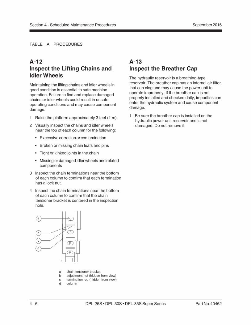
3 Inspect the chain terminations near the bottomof each column to confirm that each terminationhas a lock nut.
4 Inspect the chain terminations near the bottomof each column to confirm that the chaintensioner bracket is centered in the inspectionhole.
a chain tensioner bracketb adjustment nut (hidden from view)c termination rod (hidden from view)d column
TABLE A PROCEDURES
A-13Inspect the Breather Cap
The hydraulic reservoir is a breathing-typereservoir. The breather cap has an internal air filterthat can clog and may cause the power unit tooperate improperly. If the breather cap is notproperly installed and checked daily, impurities canenter the hydraulic system and cause componentdamage.
1 Be sure the breather cap is installed on thehydraulic power unit reservoir and is notdamaged. Do not remove it.
c
a
b
d

Part No. 40462 DPL-25S • DPL-30S • DPL-35S Super Series 4 - 7
September 2016 Section 4 - Scheduled Maintenance Procedures
Table B Procedures
B-1Inspect the Electrical Wiring
Maintaining electrical wiring in good condition isessential to safe operation and good machineperformance. Failure to find and replace burnt,chafed, corroded or pinched wires could result inunsafe operating conditions and may causecomponent damage.
Electrocution/burn hazard. Contactwith hot or live circuits may causedeath or serious injury. Removeall rings, watches and otherjewelry.
1 Inspect the following areas for burnt, chafed,corroded and loose wires:
• All base wiring
• Inside of the ground control box
• Inside of the base junction boxes
• Hydraulic power unit
• All external machine electrical cables
• Inside of the platform control box
• DC models: battery and charger
• AC power supply cord
B-2Inspect All Welds
Weld inspections are essential to safe machineoperation and good machine performance. Failureto locate and repair damage may result in anunsafe operating condition.
1 Visually inspect the welds in the followinglocations:
• Platform and platform components
• Base
• Mast brace mounting brackets
• Ladder mounting bracket

4 - 8 DPL-25S • DPL-30S • DPL-35S Super Series Part No. 40462
September 2016Section 4 - Scheduled Maintenance Procedures
B-4Check the Battery - DC Models
Proper battery condition is essential to goodmachine performance and operational safety.Improper fluid levels or damaged cables andconnections can result in component damage andhazardous conditions.
Batteries contain acid. Avoidspilling or contacting battery acid.Neutralize battery acid spills withbaking soda and water.
1 Put on protective clothing and eye wear.
2 Slide open the battery cover to access thecharger and the battery. The cover mustremain open for the entire charging cycle.
3 Remove the battery vent caps and check thespecific gravity with a hydrometer.
4 Check the battery acid level. If needed,replenish with distilled water to cover thebattery plates. Do not overfill.
5 Install the battery vent caps.
6 Set timer based on the amount of use:
Light Use—less than 15 lifting cycles: Set to 7hours.
Heavy Use—greater than 15 lifting cycles: Setto the ON position.
7 The charger will automatically shut off at theend of the set period.
Note: If ammeter drops to 3A or less within the first15 minutes, the battery is fully charged.
8 Observe charger ammeter after one hour toconfirm charging amperage has dropped.
Note: If amperage does not drop, the battery is badand needs to be replaced.
TABLE B PROCEDURES
B-3Check the Lifting ChainAdjustments
Maintaining proper adjustment of the lifting chainsis essential to safe machine operation. Failure tomaintain proper chain adjustment could result inunsafe operating conditions and may causecomponent damage.
1 Lower the platform.
2 Lower the platform side guard rails to thestowed position.
3 Measure the maximum height of the machine.
Result: The machine should be no taller thanspecification.
Note: If measurement does not meet specification,adjust the chains. See Repair procedure 5-3, Howto Adjust the Lifting Chains.
Specifications
Model Height
DPL-25S 78 inches 197.8 cm
DPL-30S 78 inches 197.8 cm
DPL-35S 78 inches 197.8 cm

Part No. 40462 DPL-25S • DPL-30S • DPL-35S Super Series 4 - 9
September 2016 Section 4 - Scheduled Maintenance Procedures
TABLE B PROCEDURES
9 Remove the battery vent caps. Check thebattery acid level. If needed, replenish withdistilled water to the bottom of the battery filltube. Do not overfill.
10 Install the battery vent caps.
B-5Clean and Lubricate the Columns
Clean and properly lubricated columns areessential to good machine performance and safeoperation. Extremely dirty conditions may requirethat the columns be cleaned and lubricated moreoften.
1 Raise the platform to the maximum height.
2 Visually inspect the inner and outer channels ofthe columns for debris or foreign material. Ifnecessary, use a mild cleaning solvent to cleanthe columns.
This procedure will require the useof additional access equipment.Do not place ladders or scaffoldon or against any part of themachine. Performing thisprocedure without the proper skillsand tools may result in death orserious injury. Dealer service isstrongly recommended.
3 If needed, lubricate the inner and outerchannels of the columns with a dry siliconespray or silicone wax (Genie part no. 90337).
B-6Test the Lifting Capacity
Proper lifting capacity is essential to safe machineoperation. Improper lifting capacity adjustmentcould allow machine to be overloaded and maycause death or serious injury.
This procedure requires specificrepair skills, lifting equipment anda suitable workshop. Attemptingthis procedure without these skillsand tools may result in death orserious injury and significantcomponent damage. Dealerservice is strongly recommended.
1 Place the maximum load capacity in theplatform. Refer to the operator's manual or theload capacity decal on the machine todetermine the maximum load capacity. Be surethe load is secure.
2 Raise the platform slightly.
Result: The hydraulic power unit should raisethe platform.
3 Fully lower the platform.
4 Add an additional 30 pounds (14 kg) to theplatform. Secure the additional weight.
5 Raise the platform slightly.
Result: The hydraulic power unit should not beable to raise the platform.
Note: If the hydraulic power unit is unable to liftrated load or lifts more than rated load, see Repairprocedure 3-6, How to Adjust the Pressure ReliefValve.

4 - 10 DPL-25S • DPL-30S • DPL-35S Super Series Part No. 40462
September 2016Section 4 - Scheduled Maintenance Procedures
B-8Adjust the Sequencing Cables
Maintaining proper adjustment of the sequencingcables is essential for safe machine operation. Anunsafe working condition exists if the sequencingcables are improperly adjusted. A frequent checkof the sequencing cables allows the inspector toidentify changes in the operating condition thatmight indicate damage.
1 Fully lower the platform.
2 Check the tension on each sequencing cable bygrasping the cable halfway down the columnand pulling the cable from one side then to theother. Measure the total distance between thetwo points (this is the maximum deflection).
Specification
Maximum Deflection 11/2 to 21/2 inches
3.8 to 6.4 cm
3 Hold the end of the cable from turning andadjust the tension nut to obtain correct tension(deflection). Turn the adjustment nut clockwiseto increase the tension or counterclockwise todecrease the tension.
Component damage hazard. Donot exceed the recommendedtension.
4 Re-check the tension on each sequencing cable.
5 Repeat adjustment for each cable as required.
6 Raise and lower the platform through threecomplete cycles and re-check the deflection.
TABLE B PROCEDURES
B-7Test the Power To PlatformOperation
AC power to the platform is intended to be anextension cord to the platform for using hand tools.
1 Connect an appropriate extension cord to theAC power supply cord at the base of themachine.
2 In the platform, plug a power drill (or similartool) into the AC outlet.
Result: The tool should operate normally.
Note: GFCI outlet may require that the outlet bereset with the reset button.
Part No. 40462 DPL-25S • DPL-30S • DPL-35S Super Series 4 - 11
September 2016 Section 4 - Scheduled Maintenance Procedures
TABLE B PROCEDURES
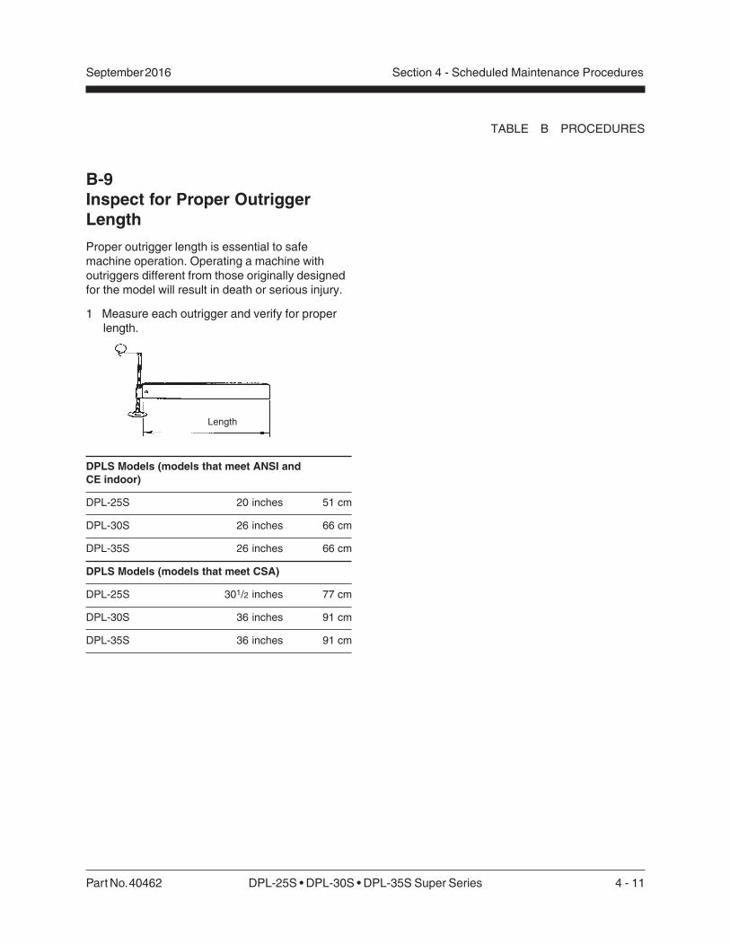
B-9Inspect for Proper OutriggerLength
Proper outrigger length is essential to safemachine operation. Operating a machine withoutriggers different from those originally designedfor the model will result in death or serious injury.
1 Measure each outrigger and verify for properlength.
DPLS Models (models that meet ANSI andCE indoor)
DPL-25S 20 inches 51 cm
DPL-30S 26 inches 66 cm
DPL-35S 26 inches 66 cm
DPLS Models (models that meet CSA)
DPL-25S 301/2 inches 77 cm
DPL-30S 36 inches 91 cm
DPL-35S 36 inches 91 cm
Length

4 - 12 DPL-25S • DPL-30S • DPL-35S Super Series Part No. 40462
September 2016Section 4 - Scheduled Maintenance Procedures
5 Inspect each idler wheel for the following:
• Excessive wear on the side flanges
• Unusual wear
• Movement side to side in excess of0.040 inches (1 mm)
• Any movement of wheel front to back
a idler wheelb spacerc lifting chain
Note: If idler wheel inspection results in ameasurement that is not within specification, referto Repair procedure 5-2, How to Assemble theMast.
6 Adjust the sequencing cables. See B-8, Adjustthe Sequencing Cables.
c
a
b
C-1Inspect and Lubricate the Casters
Extremely dirty conditions may require that thecasters be inspected and lubricated more often.
1 Visually inspect each caster for cuts, cracks orunusual wear.
2 Move the machine on a flat smooth surface andcheck that the casters roll smoothly.
3 Pump grease into the caster until it can be seencoming out of the bearing seal gap.
Grease Type Lithium-based
C-2Inspect the Mast Assembliesfor Wear
Detection of excessive or unusual wear in the mastassembly is essential for safe machine operation.An unsafe working condition exists if the mastassembly has excessive wear and/or does notoperate smoothly, free of hesitation and binding.
1 Raise the platform until 3 to 5 inches (7.6 to12.7 cm) of the top of each column is visible.
2 Visually inspect the top of each column forclearance between the roller wheels and theadjacent column surface.
Result: There should be a equal amount ofdistance between the roller wheel and thecolumn on each side.
Note: If mast inspection results in a measurementthat is not within specification, refer to Repairprocedure 5-4, How to Adjust the Glide Pads.
3 Loosen but do not remove the adjustment nut onthe sequencing cable.
4 Raise the platform approximately 3 feet (1 m).
Table C Procedures
Part No. 40462 DPL-25S • DPL-30S • DPL-35S Super Series 4 - 13
September 2016 Section 4 - Scheduled Maintenance Procedures
TABLE C PROCEDURES
C-4Replace the Hydraulic Oil
Replacement of the hydraulic oil is essential forgood machine performance and service life. Dirtyoil and a dirty suction strainer may cause themachine to perform poorly and continued use maycause component damage. Extremely dirtyconditions may require oil changes to beperformed more often.
1 Fully lower the platform.
2 Remove the base cover from the power unit.
3 Remove the drain plug from the hydraulicreservoir and completely drain the reservoir intoa container. Properly discard the oil.
4 Remove the power unit. See 3-3, How toRemove the Power Unit - AC Models or 3-4,How to Remove the Power Unit - DC Models.
5 Remove the reservoir from the hydraulic powerunit.
6 Remove the magnet from the reservoir andclean the magnet and reservoir, using a mildsolvent.
7 Install the magnet, then the reservoir.
8 Apply pipe thread sealant to the drain plug andre-install it in the reservoir.
9 Fill the reservoir with hydraulic oil until the levelis visible in the sight gauge on the end of thereservoir. Do not overfill.
10 Replace the breather cap with a new one.
C-3Lubricate the Lifting Chains
Lubricated chains are essential to good machineperformance and safe operation. Extremely dirtyconditions may require that the chains be cleanedand lubricated more often.
1 Raise the platform to the maximum height.
2 Lubricate each chain with a dry type spraylubricant.
This procedure will require the useof additional access equipment.Do not place ladders or scaffoldon or against any part of themachine. Performing thisprocedure without the proper skillsand tools may result in death orserious injury. Dealer service isstrongly recommended.
4 - 14 DPL-25S • DPL-30S • DPL-35S Super Series Part No. 40462
September 2016Section 4 - Scheduled Maintenance Procedures
11 Raise and lower the platform through threecomplete cycles. Add hydraulic oil if needed toallow platform to reach full height.
Component Damage Hazard. Donot allow the hydraulic reservoir tocompletely empty when raising theplatform. Pressurized air in thehydraulic system can damagehydraulic components.
Hydraulic System
Hydraulic fluid Dexron equivalent
Hydraulic reservoir capacity
AC models 5 quarts 4.7 liters
DC models 5 quarts 4.7 liters
Hydraulic System Capacity (includes reservoir)
AC models
DPL-25S 6 quarts 5.6 liters
DPL-30S 6 quarts 5.6 liters
DPL-35S 6 quarts 5.6 liters
DC models
DPL-25S 6 quarts 5.6 liters
DPL-30S 6 quarts 5.6 liters
DPL-35S 6 quarts 5.6 liters
TABLE C PROCEDURES
C-5Replacing the Auxiliary PlatformLowering Batteries
1 Turn the machine off and remove the key.
2 Remove the two ground control box coverfasteners.
3 Open the base control box and locate thebattery pack inside the base control box.
4 Remove the fasteners that hold the battery packin place.
5 Carefully slide the battery pack out of theholder.
The wires connected to the batterypack are very small. Be careful notto damage the wires.
6 Remove the old batteries from the pack.
7 Insert new batteries into the pack.
Make sure the batteries areinstalled correctly by following thediagram on the inside of thebattery pack.
8 Install the battery pack into the ground controlbox and tighten the fasteners.
9 Close the ground control box cover and tightenthe fasteners.
Part No. 40462 DPL-25S • DPL-30S • DPL-35S Super Series 5 - 1
September 2016 Section 5 - Troubleshooting Flow Charts
Observe and Obey:
Troubleshooting and repair procedures shall becompleted by a person trained and qualified onthe repair of this machine.
Immediately tag and remove from service adamaged or malfunctioning machine.
Repair any machine damage or malfunctionbefore operating the machine.
Before Troubleshooting:
Read, understand and obey the safety rules andoperating instructions printed in the Genie DPLSuper Series Operator's Manual.
Be sure that all necessary tools and testequipment are available and ready for use.
Read each appropiate flow chart thoroughly.Attempting shortcuts may produce hazardousconditions.
Be aware of the following hazards and followgenerally accepted safe workshop practices.
Electrocution/burn hazard. Contactwith electrically charged circuitsmay result in death or seriousinjury. Remove all rings, watchesand other jewelry.
Bodily injury hazard. Sprayinghydraulic oil can penetrate andburn skin. Loosen hydraulicconnections very slowly to allowthe oil pressure to dissipategradually. Do not allow oil to squirtor spray.
Perform all troubleshooting on afirm level surface.
Two persons will be required tosafely perform sometroubleshooting procedures.
Troubleshooting Flow Charts

5 - 2 DPL-25S • DPL-30S • DPL-35S Super Series Part No. 40462
September 2016Section 5 - Troubleshooting Flow Charts
General Repair Process
TROUBLESHOOTING FLOW CHARTS
About This SectionWhen a malfunction is discovered, the flow chartsin this section will help a service professionalpinpoint the cause of the problem. To use thissection, basic hand tools and certain pieces of testequipment are required—voltmeter, ohmmeter,pressure gauges.
The location of terminals mentioned in this sectioncan be found on the appropriate electrical orhydraulic schematics provided in Section 6,Schematics.
Since various degrees of a particular function lossmay occur, selecting the appropriate flow chartmay be troublesome. When a function will notoperate with the same speed or power as amachine in good working condition, refer to theflow chart which most closely describes theproblem.
Malfunctiondiscovered
Identifysymptoms
Troubleshoot
Performrepair
Return toservice problem
solved
problemstill exists
Inspectand test

Part No. 40462 DPL-25S • DPL-30S • DPL-35S Super Series 5 - 3
September 2016 Section 5 - Troubleshooting Flow Charts
Power Light WillNot Turn On -AC ModelsBe sure the keyswitch isin the appropriateposition.
Be sure the EmergencyStop buttons are pulledup to the ON position.
Be sure the groundcontrol box PC boardfuse is not blown.
Chart 1
Check the power supplywith a voltage meter.
0V AC Plug into a differentpower supply andrecheck the voltage.
110V AC
Check the voltage atterminal 3 on the keyswitch N.O. contact. PutPos. lead of voltagemeter on terminal 3 andNeg. lead on the whitewire from the AC powercord.
0V AC Repair or replace the ACpower cord and/or the 12/3 cable.
Check the voltage atterminal 4 on the keyswitch N.O. contact.
Check the voltage atterminal 2 on theEmergency Stop buttonN.C. contact.
Replace the key switchN.O. contact.
Check the voltage atterminal 1 on theEmergency Stop buttonN.C. contact.
Trace the black wire fromterminal 1 on theEmergency Stop N.C.contact back to the keyswitch N.O. contact andrepair open in wire.
Replace the EmergencyStop button N.C.contact.
Check the voltage at theblack transformer wirewhere it connects to thebrown transformer wire.
Repair open in the yellowtransformer wire betweenthe Emergency Stopbutton and thetransformer OR replacethe transformer becauseof a faulty thermal fuse.
110V AC
0V AC
110V AC
0V AC
0V AC
110V AC
0V AC
Continued on the nextpage.
110V AC
110V AC

5 - 4 DPL-25S • DPL-30S • DPL-35S Super Series Part No. 40462
September 2016Section 5 - Troubleshooting Flow Charts
CHART 1
Check the voltage atterminals 1 and 3 of 13pole terminal strip (J1).Put Pos. lead of voltagemeter on terminal 1 andNeg. lead on terminal 3.
Repair the transformerwires OR replace thetransformer.
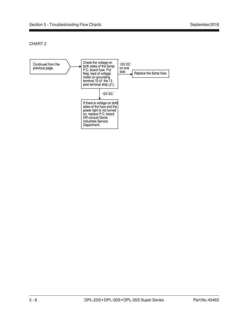
Check the voltage onboth sides of the 5 ampP.C. board fuse. PutNeg. lead of voltagemeter on groundingterminal 10 of the 13pole terminal strip (J1).
Replace the 5amp fuse.
If there is voltage on bothsides of the fuse and thepower light is not turnedon, replace P.C. boardOR consult GenieIndustries ServiceDepartment.
0V AC
14 to 16V AC
12V DCon oneside
12V DC
Continued from theprevious page.

Part No. 40462 DPL-25S • DPL-30S • DPL-35S Super Series 5 - 5
September 2016 Section 5 - Troubleshooting Flow Charts
Chart 2
Power Light WillNot Turn On -DC ModelsBe sure the keyswitch isin the appropriateposition.
Be sure the EmergencyStop buttons are pulledup to the ON position.
Be sure the batterycables are connected.
Be sure the groundcontrol box PC boardfuse is not blown.
Check the battery packvoltage.
0V DC Charge the battery ORcheck the batterycondition and replace abad battery.
Check the voltage atterminal 3 on the keyswitch N.O. contact. PutNeg. lead of voltagemeter on groundingterminal 10 of the 13 poleterminal strip (J1).
0V DC
Trace the black input wireback to the motor startsolenoid and repair openin the wire.
Check the voltage atterminal 4 on the keyswitch N.O. contact.
0V DC Replace the key switchN.O. contact.
12V DC
Check the voltage atterminal 1 on theEmergency Stop buttonN.C. contact.
Trace the black wire fromterminal 1 on theEmergency Stop N.C.contact back to the keyswitch N.O. contact andrepair open in wire.
12V DC
Check the voltage atterminal 2 on theEmergency Stop buttonN.C. contact.
0V DC
Replace the EmergencyStop button N.C.contact.
12V DC
Check the voltage atterminal 3 (black wire) of3 pole terminal strip (J2).
Trace the black wire fromterminal 3 of the 3 poleterminal strip (J2) back tothe Emergency Stopbutton N.C. contact andrepair open in the wire.
0V DC
12V DC
12V DC
0V DC
Continued on the nextpage.
12V DC
5 - 6 DPL-25S • DPL-30S • DPL-35S Super Series Part No. 40462
September 2016Section 5 - Troubleshooting Flow Charts
CHART 2
Continued from theprevious page.
Check the voltage onboth sides of the 5ampP.C. board fuse. PutNeg. lead of voltagemeter on groundingterminal 10 of the 13pole terminal strip (J1).
Replace the 5amp fuse.
If there is voltage on bothsides of the fuse and thepower light is not turnedon, replace P.C. boardOR consult GenieIndustries ServiceDepartment.
12V DC
12V DCon oneside
Part No. 40462 DPL-25S • DPL-30S • DPL-35S Super Series 5 - 7
September 2016 Section 5 - Troubleshooting Flow Charts
Chart 3
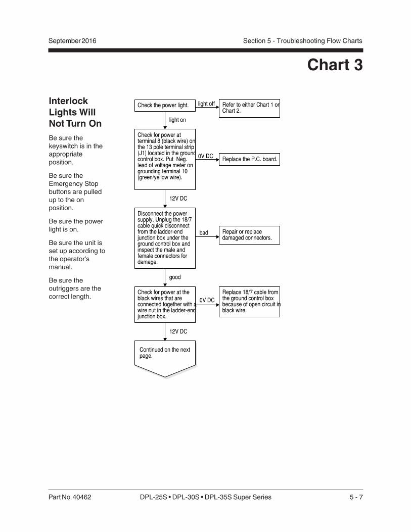
InterlockLights WillNot Turn OnBe sure thekeyswitch is in theappropriateposition.
Be sure theEmergency Stopbuttons are pulledup to the onposition.
Be sure the powerlight is on.
Be sure the unit isset up according tothe operator'smanual.
Be sure theoutriggers are thecorrect length.
Check for power atterminal 8 (black wire) onthe 13 pole terminal strip(J1) located in the groundcontrol box. Put Neg.lead of voltage meter ongrounding terminal 10(green/yellow wire).
0V DC
Check for power at theblack wires that areconnected together with awire nut in the ladder-endjunction box.
Disconnect the powersupply. Unplug the 18/7cable quick disconnectfrom the ladder-endjunction box under theground control box andinspect the male andfemale connectors fordamage.
bad Repair or replacedamaged connectors.
Replace the P.C. board.
Replace 18/7 cable fromthe ground control boxbecause of open circuit inblack wire.
12V DC
good
0V DC
12V DC
Continued on the nextpage.
Check the power light.
light on
Refer to either Chart 1 orChart 2.
light off
5 - 8 DPL-25S • DPL-30S • DPL-35S Super Series Part No. 40462
September 2016Section 5 - Troubleshooting Flow Charts
CHART 3
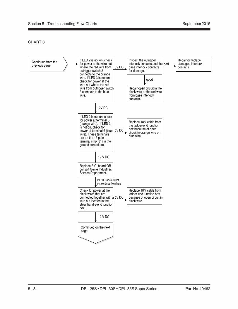
Inspect the outriggerinterlock contacts and thebase interlock contactsfor damage.
Replace P.C. board ORconsult Genie IndustriesService Department.
0V DC
12 V DC
0V DC
Continued from theprevious page.
Repair or replacedamaged interlockcontacts.
If LED 2 is not on, checkfor power at the wire nutwhere the red wire fromoutrigger switch 2connects to the orangewire. If LED 3 is not on,check for power at thewire nut where the redwire from outrigger switch3 connects to the bluewire.
good
Repair open circuit in theblack wire or the red wirefrom base interlockcontacts.
bad
12V DC
Check for power at theblack wires that areconnected together with awire nut located in thesteer handle-end junctionbox.
0V DC
Replace 18/7 cable fromthe ladder-end junctionbox because of opencircuit in orange wire orblue wire .
If LED 2 is not on, checkfor power at terminal 5(orange wire). If LED 3is not on, check forpower at terminal 6 (bluewire). These terminalsare on the 13 poleterminal strip (J1) in theground control box.
Continued on the nextpage.
Replace 18/7 cable fromladder-end junction boxbecause of open circuit inblack wire.
If LED 1 or 4 are noton, continue from here
12 V DC

Part No. 40462 DPL-25S • DPL-30S • DPL-35S Super Series 5 - 9
September 2016 Section 5 - Troubleshooting Flow Charts
Continued from theprevious page.
If LED 1 is not on, checkfor power at the wire nutwhere the red wire fromswitch 1 connects to thewhite wire. If LED 4 isnot on, check for powerat the wire nut where thered wire from switch 4connects to the redwire.
0V DC Inspect the outriggerinterlock contacts and thebase interlock contactsfor damage.
12V DC
Repair open circuit in theblack wire or the red wirefrom base interlockcontacts.
12V DC
If LED 1 is not on, checkfor power at the wire nutwhere the white wiresconnect in the ladder-endjunction box. If LED 4 isnot on, check for powerat the wire nut where thered wires connect.
good
bad Repair or replacedamaged interlockcontacts.
0V DC
Replace the 18/7 cablefrom the steer handle-endjunction box because ofopen circuit in the whitewire or in the red wire.
If LED 1 is not on, checkfor power at terminal 4(white wire). If LED 4 isnot on, check for powerat terminal 7 (red wire).These terminals are onthe 13 pole terminal strip(J1) in the ground controlbox.
0V DC
12V DC
Replace P.C. board ORconsult Genie IndustriesService Department.
Replace the 18/7 cablefrom the ladder-endjunction box because ofopen circuit in white wireor in the red wire.
CHART 3
5 - 10 DPL-25S • DPL-30S • DPL-35S Super Series Part No. 40462
September 2016Section 5 - Troubleshooting Flow Charts
Chart 4
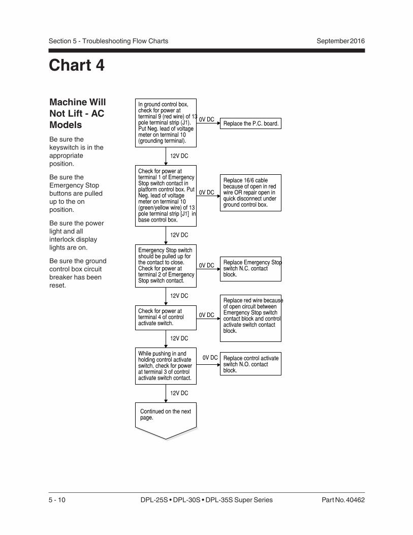
Machine WillNot Lift - ACModelsBe sure thekeyswitch is in theappropriateposition.
Be sure theEmergency Stopbuttons are pulledup to the onposition.
Be sure the powerlight and allinterlock displaylights are on.
Be sure the groundcontrol box circuitbreaker has beenreset.
0V DCReplace the P.C. board.
In ground control box,check for power atterminal 9 (red wire) of 13pole terminal strip (J1).Put Neg. lead of voltagemeter on terminal 10(grounding terminal).
Check for power atterminal 1 of EmergencyStop switch contact inplatform control box. PutNeg. lead of voltagemeter on terminal 10(green/yellow wire) of 13pole terminal strip [J1] inbase control box.
Replace 16/6 cablebecause of open in redwire OR repair open inquick disconnect underground control box.
Emergency Stop switchshould be pulled up forthe contact to close.Check for power atterminal 2 of EmergencyStop switch contact.
Replace Emergency Stopswitch N.C. contactblock.
Check for power atterminal 4 of controlactivate switch.
Replace red wire becauseof open circuit betweenEmergency Stop switchcontact block and controlactivate switch contactblock.
While pushing in andholding control activateswitch, check for powerat terminal 3 of controlactivate switch contact.
Replace control activateswitch N.O. contactblock.
0V DC
12V DC
0V DC
12V DC
0V DC
12V DC
0V DC
12V DC
12V DC
Continued on the nextpage.

Part No. 40462 DPL-25S • DPL-30S • DPL-35S Super Series 5 - 11
September 2016 Section 5 - Troubleshooting Flow Charts
CHART 4
While pushing in andholding the controlactivate switch, check forpower at terminal 4 of theup switch contact.
Replace the red wire(because of open circuit)between the controlactivate switch contactblock and the up switchcontact block.
While pushing in thecontrol activate switchand activating the upfunction, hold bothswitches and check forpower at terminal 3 of upswitch contact.
Replace up switch N.O.contact block.
While pushing in thecontrol activate switchand activating the upfunction, hold bothswitches and check forpower at terminal 13(orange wire) of 13 poleterminal strip (J1)in basecontrol box.
Replace 16/6 cablebecause of open inorange wire OR repairopen in quick disconnectunder ground control box.
Continued from theprevious page. 0V DC
12V DC
0V DC
12V DC
0V DC
While pushing in thecontrol activate switchand activating the upfunction, hold bothswitches and check forpower at terminal 11(white wire) of 13 poleterminal strip (J1) in theground control box.
0V DC Replace P.C. board ORconsult Genie IndustriesService Department.
While pushing in thecontrol activate switchand activating the upfunction, hold bothswitches and check forpower at the motorcontactor coil (terminal 1red wire). Put Neg. leadof the voltage meter onterminal 0 green/yellowwire.
Relocate Neg. lead of thevoltage meter at terminal10 (green/yellow wire) ofthe 13 pole terminal strip(J1).
Repair open circuit in redwire.
Repair open circuit ingreen/yellow wire.
12V DC
12V DC
12V DC
Continued on the nextpage.
0V DC
12V DC
0V DC
5 - 12 DPL-25S • DPL-30S • DPL-35S Super Series Part No. 40462
September 2016Section 5 - Troubleshooting Flow Charts
CHART 4
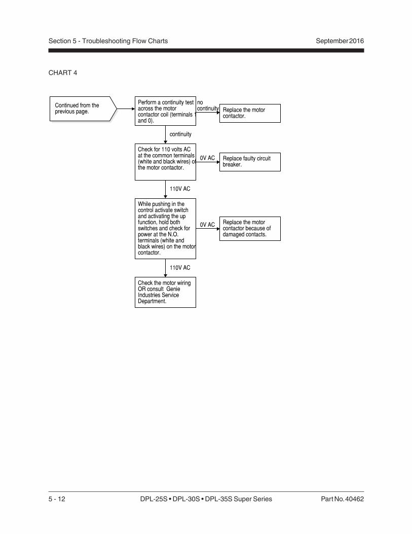
Perform a continuity testacross the motorcontactor coil (terminals 1and 0).
Replace the motorcontactor.
nocontinuity
Check for 110 volts ACat the common terminals(white and black wires) ofthe motor contactor.
Replace faulty circuitbreaker.
While pushing in thecontrol activate switchand activating the upfunction, hold bothswitches and check forpower at the N.O.terminals (white andblack wires) on the motorcontactor.
Replace the motorcontactor because ofdamaged contacts.
Check the motor wiringOR consult GenieIndustries ServiceDepartment.
Continued from theprevious page.
continuity
0V AC
110V AC
0V AC
110V AC

Part No. 40462 DPL-25S • DPL-30S • DPL-35S Super Series 5 - 13
September 2016 Section 5 - Troubleshooting Flow Charts
Chart 5
Machine WillNot Lift, ButPower UnitWill Operate- AC ModelsBe sure the powerunit reservoir is fulland the breathercap has beeninstalled.
Be sure the manuallowering cable isproperly adjusted.
While pushing in thecontrol activate switchand activating the upfunction, hold bothswitches and check forinput voltage at the N.O.valve coil on the powerunit. Wait 1 secondbefore checking voltage.Put Pos. lead of thevoltage meter on theblack wire and Neg. leadon the green/yellowgrounding wire.
Check the resistance ofthe N.O. valve coil.
0V DC
While pushing in thecontrol activate switchand activating the upfunction, hold bothswitches and check forpower at terminal 12(black wire) of the 13 poleterminal strip (J1). This isa 1 second ON timedelayed terminal.
0V DC Replace P.C. board.
Replace or repair blackwire because of an opencircuit.
infiniteohms Replace N.O. valve coil.
Tee in pressure gauge atpressure port (stampedP) of power unit. Push inthe control activateswitch, activate the upfunction, hold bothswitches and check thepressure.
12V DC
7 ohms
1800 to2000 psi
Inspect the mastassemblies for amechanical bind such asforiegn objects that couldhave fallen in betweencolumns.
Continued on the nextpage.
1800 to2000 psi
On the power unit,remove the return to tankhose off of the T portfitting and plug the hosefitting, leaving 3000 psigauge teed in at the Pport fitting. Push in thecontrol activate switch,activate the up function,hold and check thepressure.
Activate the up functionand check for voltage atthe N.C. down valve coils(yellow wire) at the barrelend of each liftingcylinder.
0V DC
12V DC
Replace defective N.O.contact block for downfunction in platformcontrol box.
less than 1800 psi
12V DC
less than 1800 psi

5 - 14 DPL-25S • DPL-30S • DPL-35S Super Series Part No. 40462
September 2016Section 5 - Troubleshooting Flow Charts
CHART 5
Continued from theprevious page.
On the power unit,remove and inspect theN.O. valve forcontamination or damage.Clean, repair or replacevalve and then performpressure test again.
less than 1800 psi
Adjust the pressure reliefvalve. See Repairprocedure, How to Adjustthe Pressure ReliefValve, and then performpressure test again.
less than 1800 psi
Consult Genie IndustriesService Department.
Part No. 40462 DPL-25S • DPL-30S • DPL-35S Super Series 5 - 15
September 2016 Section 5 - Troubleshooting Flow Charts
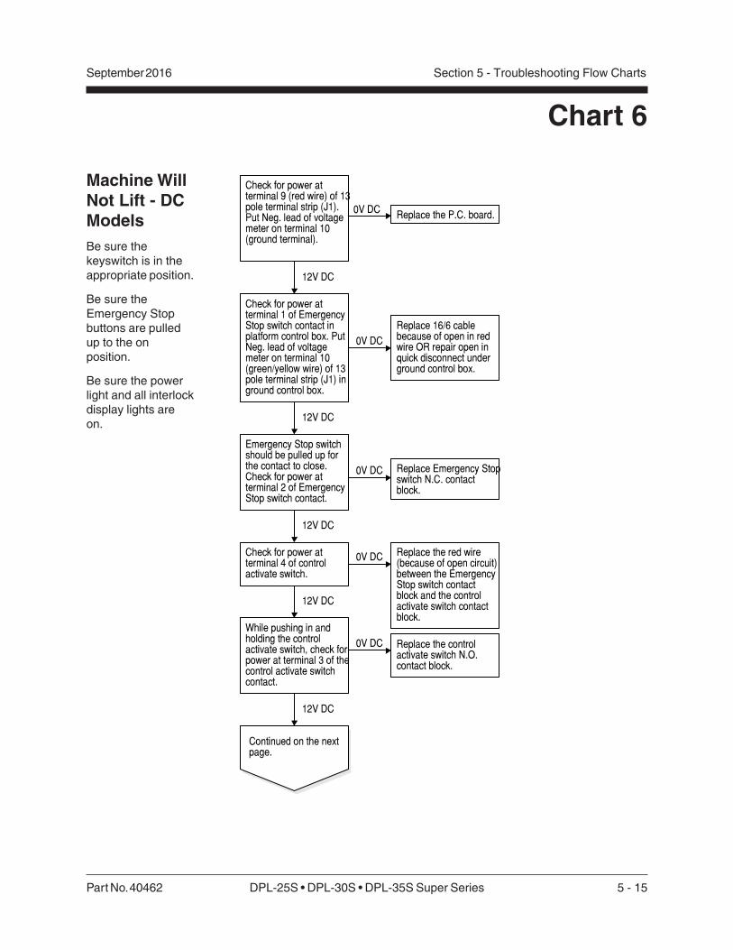
Chart 6
Machine WillNot Lift - DCModelsBe sure thekeyswitch is in theappropriate position.
Be sure theEmergency Stopbuttons are pulledup to the onposition.
Be sure the powerlight and all interlockdisplay lights areon.
0V DCReplace the P.C. board.
Check for power atterminal 9 (red wire) of 13pole terminal strip (J1).Put Neg. lead of voltagemeter on terminal 10(ground terminal).
Check for power atterminal 1 of EmergencyStop switch contact inplatform control box. PutNeg. lead of voltagemeter on terminal 10(green/yellow wire) of 13pole terminal strip (J1) inground control box.
Replace 16/6 cablebecause of open in redwire OR repair open inquick disconnect underground control box.
Emergency Stop switchshould be pulled up forthe contact to close.Check for power atterminal 2 of EmergencyStop switch contact.
Replace Emergency Stopswitch N.C. contactblock.
Check for power atterminal 4 of controlactivate switch.
Replace the red wire(because of open circuit)between the EmergencyStop switch contactblock and the controlactivate switch contactblock.
While pushing in andholding the controlactivate switch, check forpower at terminal 3 of thecontrol activate switchcontact.
Replace the controlactivate switch N.O.contact block.
12V DC
0V DC
12V DC
0V DC
12V DC
0V DC
12V DC
12V DC
0V DC
Continued on the nextpage.

5 - 16 DPL-25S • DPL-30S • DPL-35S Super Series Part No. 40462
September 2016Section 5 - Troubleshooting Flow Charts
CHART 6
Continued from theprevious page.
While pushing in andholding the controlactivate switch, check forpower at terminal 4 of theup switch contact.
Replace the red wire(because of open circuit)between the controlactivate switch contactblock and the up switchcontact block.
While pushing in thecontrol activate switchand activating the upfunction, hold bothswitches and check forpower at terminal 3 of theup switch contact.
Replace the up switchN.O. contact block.
While pushing in thecontrol activate switchand activating the upfunction, hold bothswitches and check forpower at terminal 13(orange wire) of the 13pole terminal strip (J1) inthe ground control box.
Replace the 16/6 cablebecause of open in theorange wire OR repairopen in the quickdisconnect under groundcontrol box.
12V DC
0V DC
0V DC
12V DC
0V DC
While pushing in thecontrol activate switchand activating the upfunction, hold bothswitches and check forpower at terminal 11(white wire) of the 13 poleterminal strip (J1) in theground control box.
12V DC
0V DC Replace P.C. board ORconsult Genie Industriesservice Department.
12V DC
Continued on the nextpage.

Part No. 40462 DPL-25S • DPL-30S • DPL-35S Super Series 5 - 17
September 2016 Section 5 - Troubleshooting Flow Charts
CHART 6
Continued from theprevious page.
While pushing in thecontrol activate switchand activating the upfunction, hold bothswitches and check forpower at the motorcontactor coil (positiveterminal white wire). PutNeg. lead of the voltagemeter on the negativeterminal (green/yellowwire).
0V DC
Relocate the Neg. lead ofthe voltage meter atterminal 10 (green/yellowwire) of the 13 poleterminal strip (J1) in theground control box.
12V DC
Repair open circuit in thegreen/yellow wire.
0V DC Repair open circuit in thered wire.
12V DC
Perform a continuity testacross the motorcontactor coil.
nocontinuity Replace the motor
contactor.
continuity
While pushing in thecontrol activate switchand activating the upfunction, hold bothswitches and check forpower at the N.O. side ofthe motor contactor(number 4 weld cable to12 volt motor).
0V DC Replace the motorcontactor because ofdamaged contacts.
12V DC
Perform a continuity testacross the 12 volt motor.
nocontinuity Replace the motor
brushes OR the 12 voltDC motor.
continuity
Check the condition ofthe battery OR consultGenie Industries ServiceDepartment.

5 - 18 DPL-25S • DPL-30S • DPL-35S Super Series Part No. 40462
September 2016Section 5 - Troubleshooting Flow Charts
Chart 7
Machine WillNot Lift, ButPower UnitWill Operate -DC ModelsBe sure the powerunit reservoir is fulland the breather caphas been installed.
Be sure the manuallowering cable isproperly adjusted.
While pushing in thecontrol activate switchand activating the upfunction, hold bothswitches and check forinput voltage at the N.O.valve coil on the powerunit. Put Pos. lead of thevoltage meter on thewhite wire and Neg. leadon the green/yellowgrounding wire.
0V DC
12V DC
Check the resistance ofthe N.O. valve coil.
infiniteohms Replace the N.O. valve
coil.
7 ohms
Replace or repair thewhite wire between themotor contactor coil andthe N.O. valve coilbecause of an opencircuit.
Tee in a 3000 psipressure gauge at thepressure port fitting(stamped P) of the powerunit. Push in the controlactivate switch, activatethe up function, hold bothswitches and check thepressure.
1800 to2000 psi
less tnan 1800 psi
Inspect the mastassemblies for amechanical bind such asforeign objects that couldhave fallen in betweenthe columns.
On the power unit,remove the return to tankhose off of the T portfitting and plug the hosefitting, leaving the 3000psi gauge teed in at the Pport fitting. Push in thecontrol activate switch,activate the up function,hold both switches andcheck the pressure.
less than 1800 psi
1800 to2000 psi
Activate the up functionand check for voltage atthe N.C. down valve coils(yellow wire) at the barrelend of each lift cylinder.
Continued on the nextpage.
12V DC
Replace defective N.O.contact block for downfunction in the platformcontrol box.
0V DC
Remove the N.C. downvalves and inspect forcontamination or damageOR consult GenieIndustries ServiceDepartment.

Part No. 40462 DPL-25S • DPL-30S • DPL-35S Super Series 5 - 19
September 2016 Section 5 - Troubleshooting Flow Charts
CHART 7
Continued from theprevious page.
On the power unit,remove and inspect theN.O. valve forcontamination or damage.Clean, repair or replacevalve and then performpressure test again.
less than 1800 psi
Adjust the pressure reliefvalve. See Repairprocedure, How to Adjustthe Pressure Relief Valveand then performpressure test again.
less than 1800 psi
Consult Genie IndustriesService Department.
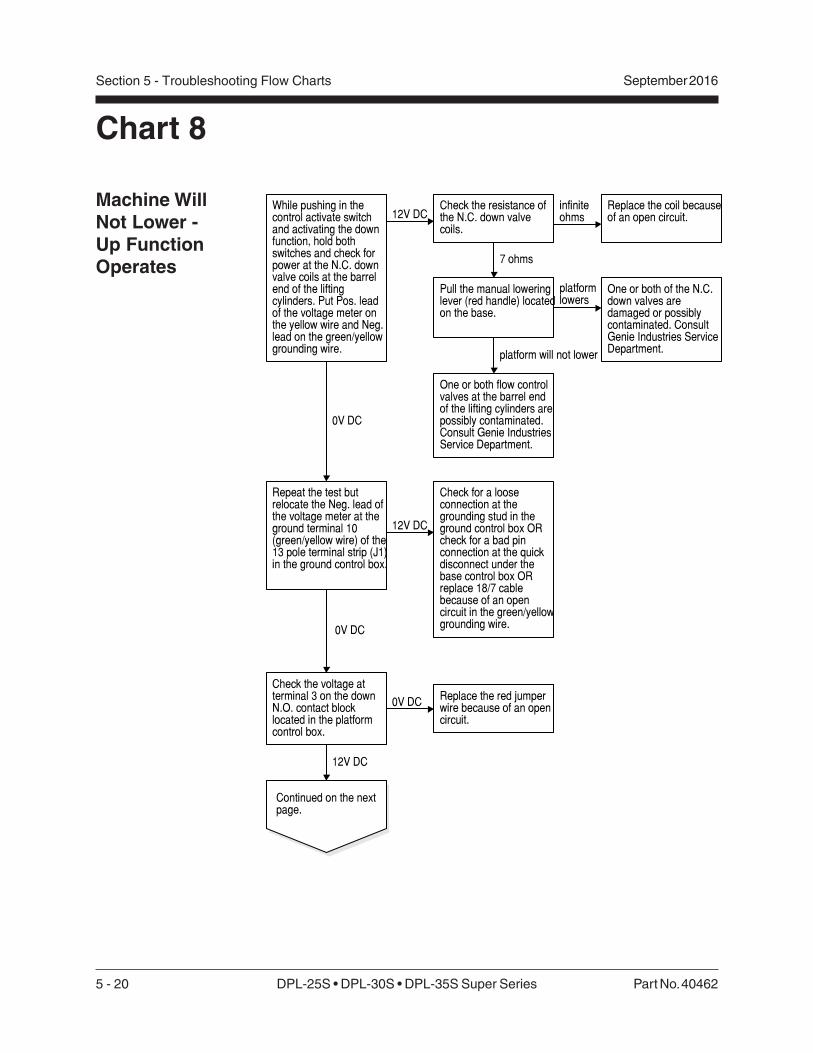
5 - 20 DPL-25S • DPL-30S • DPL-35S Super Series Part No. 40462
September 2016Section 5 - Troubleshooting Flow Charts
Chart 8
Machine WillNot Lower -Up FunctionOperates
While pushing in thecontrol activate switchand activating the downfunction, hold bothswitches and check forpower at the N.C. downvalve coils at the barrelend of the liftingcylinders. Put Pos. leadof the voltage meter onthe yellow wire and Neg.lead on the green/yellowgrounding wire.
12V DC
0V DC
Check the resistance ofthe N.C. down valvecoils.
Repeat the test butrelocate the Neg. lead ofthe voltage meter at theground terminal 10(green/yellow wire) of the13 pole terminal strip (J1)in the ground control box.
12V DC
Check for a looseconnection at thegrounding stud in theground control box ORcheck for a bad pinconnection at the quickdisconnect under thebase control box ORreplace 18/7 cablebecause of an opencircuit in the green/yellowgrounding wire.
7 ohms
infiniteohms
Pull the manual loweringlever (red handle) locatedon the base.
Replace the coil becauseof an open circuit.
platformlowers
One or both of the N.C.down valves aredamaged or possiblycontaminated. ConsultGenie Industries ServiceDepartment.
platform will not lower
One or both flow controlvalves at the barrel endof the lifting cylinders arepossibly contaminated.Consult Genie IndustriesService Department.
Check the voltage atterminal 3 on the downN.O. contact blocklocated in the platformcontrol box.
12V DC
0V DCReplace the red jumperwire because of an opencircuit.
Continued on the nextpage.
0V DC

Part No. 40462 DPL-25S • DPL-30S • DPL-35S Super Series 5 - 21
September 2016 Section 5 - Troubleshooting Flow Charts
CHART 8
Continued from theprevious page.
Activate the downfunction and check thevoltage at terminal 4 (bluewire) of the N.O. downcontact block.
0V DC Replace the N.O. downcontact block because ofan open circuit.
12V DC
Inspect pin 2 for a defectin the quick disconnectlocated under the groundcontrol box OR replacethe 16/6 cable because ofan open circuit in the bluewire.
12V DC
Check the voltage atterminal 2 on the N.O.auxilary down contactblock in the base controlbox.
0V DC
Inspect pin 5 for a defectin the quick disconnectlocated under the groundcontrol box OR replacethe 18/7 cable because ofopen circuit in the yellowwire.

5 - 22 DPL-25S • DPL-30S • DPL-35S Super Series Part No. 40462
September 2016Section 5 - Troubleshooting Flow Charts
Chart 9
Platform WillNot Hold InUp PositionBe sure manuallowering cable isproperly adjusted.
Activate the platform upfunction whilesimultaneously activatingthe manual loweringvalve. Test the unit.
platform wont hold up
platformholds up
On the power unit,remove the return to tankhose off the T port fittingand put it into a bucketand activate the platfomup function. Check forleaking from the hose.
Inspect the hydraulicsystem forcontamination.
leaking Replace or repair bothN.C. down valves.
not leaking
While platform is drifting,is the motor spinningbackwards?
yes
no
Replace or repair all 3check valves.The firstand second are located ineach lifting cylinder andthe third is located in thepower unit.
Remove the liftingcylinders and replacedamaged piston seal ORcontact Genie IndustriesService Department.
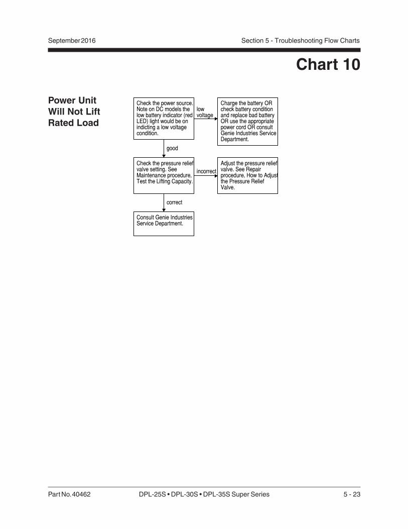
Part No. 40462 DPL-25S • DPL-30S • DPL-35S Super Series 5 - 23
September 2016 Section 5 - Troubleshooting Flow Charts
Chart 10
Power UnitWill Not LiftRated Load
Check the pressure reliefvalve setting. SeeMaintenance procedure,Test the Lifting Capacity.
Check the power source.Note on DC models thelow battery indicator (redLED) light would be onindicting a low voltagecondition.
lowvoltage
Adjust the pressure reliefvalve. See Repairprocedure, How to Adjustthe Pressure ReliefValve.
incorrect
correct
Charge the battery ORcheck battery conditionand replace bad batteryOR use the appropriatepower cord OR consultGenie Industries ServiceDepartment.
Consult Genie IndustriesService Department.
good
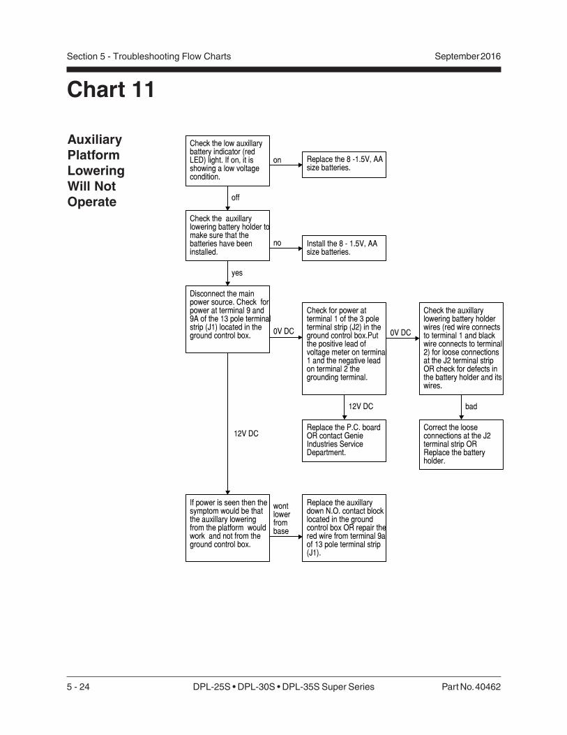
5 - 24 DPL-25S • DPL-30S • DPL-35S Super Series Part No. 40462
September 2016Section 5 - Troubleshooting Flow Charts
Chart 11
AuxiliaryPlatformLoweringWill NotOperate
Check the low auxillarybattery indicator (redLED) light. If on, it isshowing a low voltagecondition.
off
on
Disconnect the mainpower source. Check forpower at terminal 9 and9A of the 13 pole terminalstrip (J1) located in theground control box.
Replace the 8 -1.5V, AAsize batteries.
0V DC
Replace the P.C. boardOR contact GenieIndustries ServiceDepartment.
If power is seen then thesymptom would be thatthe auxillary loweringfrom the platform wouldwork and not from theground control box.
wontlowerfrombase
Replace the auxillarydown N.O. contact blocklocated in the groundcontrol box OR repair thered wire from terminal 9aof 13 pole terminal strip(J1).
Check for power atterminal 1 of the 3 poleterminal strip (J2) in theground control box.Putthe positive lead ofvoltage meter on terminal1 and the negative leadon terminal 2 thegrounding terminal.
0V DC
12V DC
Check the auxillarylowering battery holderwires (red wire connectsto terminal 1 and blackwire connects to terminal2) for loose connectionsat the J2 terminal stripOR check for defects inthe battery holder and itswires.
Check the auxillarylowering battery holder tomake sure that thebatteries have beeninstalled.
yes
Install the 8 - 1.5V, AAsize batteries.
no
bad
Correct the looseconnections at the J2terminal strip ORReplace the batteryholder.
12V DC

Part No. 404632 DPL-25S • DPL-30S • DPL-35S Super Series 6 - 1
September 2016 Section 6 • Schematics
Schematics
Observe and Obey:
Troubleshooting and repair procedures shall becompleted by a person trained and qualified onthe repair of this machine.
Immediately tag and remove from service adamaged or malfunctioning machine.
Repair any machine damage or malfunctionbefore operating the machine.
Before Troubleshooting:
Read, understand and obey the safety rulesand operating instructions printed in theGenie AWP Super Series Operator's Manualand the Genie IWP Super Series Operator'sManual.
Be sure that all necessary tools and testequipment are available and ready for use.
About This SectionThere are two groups of schematics in this section.
Electrical Schematics
Electrocution/burn hazard. Contactwith electrically charged circuitsmay result in death or seriousinjury. Remove all rings, watchesand other jewelry.
Hydraulic Schematics
Bodily injury hazard. Sprayinghydraulic oil can penetrate andburn skin. Loosen hydraulicconnections very slowly to allowthe oil pressure to dissipategradually. Do not allow oil to squirtor spray.
General Repair Process
Malfunctiondiscovered
Identifysymptoms
Troubleshoot
Performrepair
Return toservice problem
solved
problemstill exists
Inspectand test
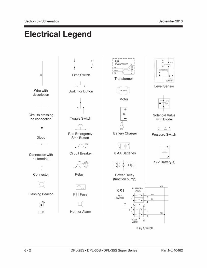
6 - 2 DPL-25S • DPL-30S • DPL-35S Super Series Part No. 40462
September 2016Section 6 • Schematics
CB2
N.O.
S7LEVEL
SENSOR
LEVEL SENSOR
CIRCUIT BOARD
RD
-
+
NC NO C
MOTOR
KS1
BK
B
B1
3
1
4
2
BK
BN
BK
RDKEY
SWITCH
PLATFORM
MODE
WH
WH
BASE
MODE
-
+
+
-
U9
U9TRANSFORMER
RD
RD
RD/YLBN
BL
BK
YL
WH
87A 85
8630
87
PR4
Electrical Legend
Wire withdescription
Circuits crossingno connection
Diode
Connection withno terminal
Connector
F11 Fuse
Red EmergencyStop Button
Toggle Switch
LED
Limit Switch
8 AA Batteries
12V Battery(s)
Switch or Button
Circuit Breaker
Transformer
Solenoid Valvewith Diode
Relay
Horn or Alarm
Flashing Beacon
Battery Charger Pressure Switch
Key Switch
Level Sensor
Power Relay(function pump)
Motor

Part No. 404632 DPL-25S • DPL-30S • DPL-35S Super Series 6 - 3
September 2016 Section 6 • Schematics
Hydraulic Legend
Motor
Cylinder
Check Valve
PumpFilter
Pressure compensatedflow control
Solenoid operateddump valve
2 position 2 waydirectional valve
Adjustable relief valve

6 - 4 DPL-25S • DPL-30S • DPL-35S Super Series Part No. 40462
September 2016Section 6 • Schematics
Note: Use this legendfor the schematic onthe opposing page.
WIRE COLOR LEGEND
Color Description
BL Blue
BK Black
GN/YL Green/Yellow
OR Orange
RD Red
WH White
YL Yellow

Electrical SchematicDPL Super Series DC Models
(before serial number DPL07-1499
September 2016
1
2
3
4
5
6
7
8
N M L K J I H G F E D C B A
Section 6 • Schematics
Part No. 40462 DPL-25S • DPL-30S • DPL-35S Super Series 6 - 5

Electrical SchematicDPL Super Series DC Models
(before serial number DPL07-1499)
September 2016Section 6 • Schematics
Note: Use these 2legends for theschematic on theopposing page.
ABBREVIATION LEGEND Item Description
Battery B
B2 = 12V Battery B4 = 8 AA Batteries
D5 Power supply AC
Enclosure EN
EN1 = Platform control box EN2 = Ground control box
EN4 = Power to platform GFCI receptacle
F11 Fuse, 175 AMP
FB2 Warning light
GND Ground
H4 Descent alarm
KS1 Key switch ground/platform
Led or light L
L5 = Power indicator (ground) L6 = Low battery indicator for auxiliary (ground)
L7 = Low battery indicator — main (ground) L12 = Outrigger — front left (ground) L13 = Outrigger — front right (ground) L14 = Outrigger — rear left (ground) L15 = Outrigger — rear right (ground)
M5 Hydraulic power unit
N.C. Normally closed
N.O Normally open
*N Note with description *N17 = Narrow platform units: WH and BK wires replace BL and OR wires *N27 = Units with out plug:
WH and BK wires replace BL and BN wires
Power switch P
P1 = Emergency Stop button at ground controls P2 = Emergency Stop button at platform controls
Quick disconnect QD
QD1 = Battery quick disconnect QD3 = Control cable — to platform control box QD4 = Control cable — to base
Switch SW
SW 8 = Control activate SW11 = Platform up/down SW12 = Auxiliary down SW13 = Outrigger interlock — front left SW14 = Outrigger interlock — front right
SW15 = Outrigger interlock — rear left SW16 = Outrigger interlock — rear right
Electronic component U
U9 = Battery Charger U10 = PC board
Wiring component W
W3 = Terminal strip — 3 pole 3 pin (U10) W4 = Terminal strip — 14 pole 14 pin (U10)
W5 = Terminal strip — 5 pole 10 pin
Valve coil Y
Y7 = Platform down Y30 = Normally open dump valve
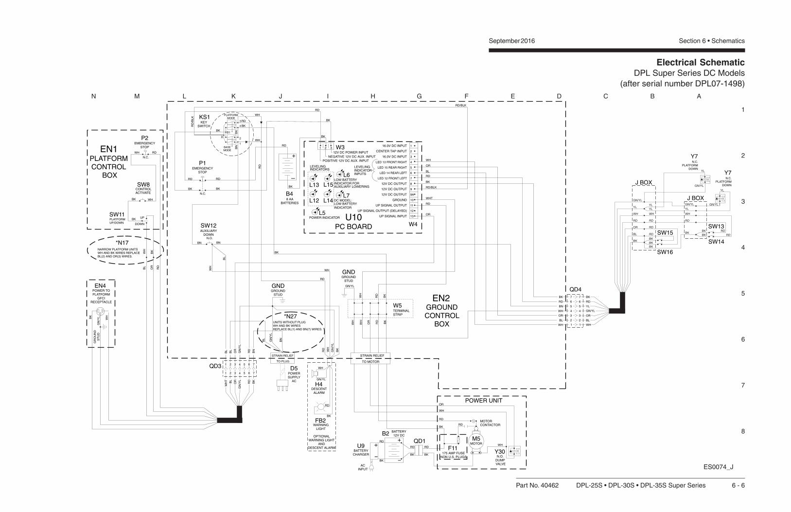
Electrical SchematicDPL Super Series DC Models
(after serial number DPL07-1498)
September 2016
1
2
3
4
5
6
7
8
N M L K J I H G F E D C B A
Section 6 • Schematics
Part No. 40462 DPL-25S • DPL-30S • DPL-35S Super Series 6 - 6
RD/BLK
RD
WHT
OR
RD
BK
BK
BK
RD RD
+
-
8 AABATTERIES
12V DC OUTPUT
12V DC OUTPUT
GROUND
UP SIGNAL OUTPUT
UP SIGNAL INPUT
UP SIGNAL OUTPUT (DELAYED)
1
2
3
4
5
6
7
8
9
9A
10
11
12
13
1 2 3
12V DC OUTPUT
POSITIVE 12V DC AUX. INPUT
NEGATIVE 12V DC AUX. INPUT
12V DC POWER INPUT
16.0V DC INPUT
16.0V DC INPUT
CENTER TAP INPUT
KS1
P1EMERGENCY
STOP
N.C.
LEVELINGINDICATORINPUTS
BL
BK
RD
OR
WH
GN
/YL
BL
STRAIN RELIEF
TO MOTOR
BN
WH
WH
OR
RD
RD
RD
BK
BK
BK
RD
WH
OR
WH
BK
BK
BL
BNBN
GN/YL
BK
BK BK
-
12V DCBATTERY
+
POWER UNIT
MOTOR
MOTORCONTACTOR
BK
WHNARROW PLATFORM UNITS
WH AND BK WIRES REPLACEBL(2) AND OR(3) WIRES.
RD
BL
OR
RDWH
WHBK
BKUP
DOWN
N.C.
B4
W4
W3
B2
POWER INDICATOR
DC MODEL:LOW BATTERYINDICATOR
L5
L6
L7
LOW BATTERYINDICATOR FORAUXILIARY LOWERING
U10PC BOARD
L13 L15
L14L12
LEVELINGINDICATORS
GROUNDCONTROL
BOX
EN2GROUND
STUD
GND
N.O.DUMPVALVE
Y30
M5
GR
OU
ND
ST
UD
GN
/YLBK
WH
POWER TOPLATFORM
GFCIRECEPTACLE
EN4
POWERSUPPLY
AC
D5
SW11
*N17
PLATFORMUP/DOWN
ACTIVATECONTROLSW8
P2EMERGENCY
STOP
PLATFORMCONTROL
BOX
EN1
SW12AUXILIARY
DOWNN.O.
W5TERMINALSTRIP
QD1
LED 13 FRONT RIGHT
LED 15 REAR RIGHT
LED 14 REAR LEFT
LED 12 FRONT LEFT
B
B1
3
1
4
2
RD
RD/BLK
RD
/BL
K
BK
BK
RD
WH
BN
BK
RD
STRAIN RELIEF
TO PLUG
+
-
RD
BK
ACINPUT
U9BATTERYCHARGER
F11175 AMP FUSE
NON U.S. PLUGS
KEYSWITCH
PLATFORMMODE
WH
WH
RD
RD
RD
WH
GN
/YL
BK
WHWH
WH
GN/YL
BK
RD
OPTIONALWARNING LIGHT
ANDDESCENT ALARM
H4DESCENT
ALARM
FB2WARNING
LIGHT
BASEMODE
UNITS WITHOUT PLUGWH AND BK WIRESREPLACE BL(1) AND BN(7) WIRES.
*N27
ES0074_J
GROUNDSTUD
GND
RD
WH
GN/YL
YL
RD
OR
BK
YL
YL
WH
RD
RD
RD
BK
BK
BK
GN/YL
GN/YL
YL
WH
RD
BL BK
GN/YL
YL
RD
RDBK
BK
YL
J BOX
J BOX
SW13
SW14
SW15
SW16
Y7N.C.
PLATFORMDOWN
Y7N.C.
PLATFORMDOWN
4
GN
/YL
BL
OR
RD
BN
BL
QD3 1 32 65 7
41 32 65 7
GN
/YL
WH
T
OR
RD
BK
BL
BK
WH
OR
BL
WH
RD
BN
QD4
4
1
3
2
6
5
7
4
1
3
2
6
5
7
WH
BL
OR
YL
GN/YL
RD
BK
Electrical SchematicDPL Super Series DC Models
(after serial number DPL07-1498)
September 2016Section 6 • Schematics
Note: Use these 2legends for theschematic on theopposing page.
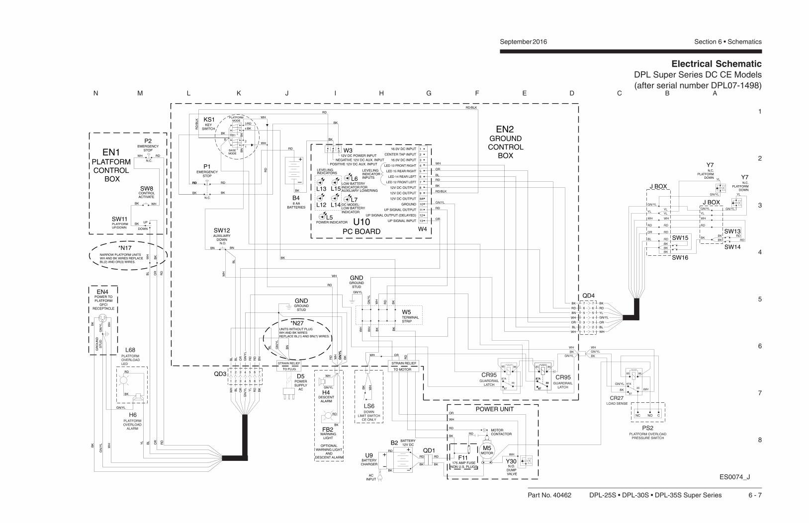
1
2
3
4
5
6
7
8
N M L K J I H G F E D C B A
Part No. 40462 DPL-25S • DPL-30S • DPL-35S Super Series 6 - 7
Electrical SchematicDPL Super Series DC CE Models
(after serial number DPL07-1498)
September 2016 Section 6 • Schematics
RD/BLK
RD
OR
RD
BK
BK
RD RD
+
-
8 AABATTERIES
12V DC OUTPUT
12V DC OUTPUT
GROUND
UP SIGNAL OUTPUT
UP SIGNAL INPUT
UP SIGNAL OUTPUT (DELAYED)
1
2
3
4
5
6
7
8
9
9A
10
11
12
13
1 2 3
12V DC OUTPUT
POSITIVE 12V DC AUX. INPUT
NEGATIVE 12V DC AUX. INPUT
12V DC POWER INPUT
16.0V DC INPUT
16.0V DC INPUT
CENTER TAP INPUT
KS1
P1EMERGENCY
STOP
N.C.
LEVELINGINDICATORINPUTS
BL
BK
RD
OR
WH
GN
/YL
BL
STRAIN RELIEF
TO MOTOR
WH
WH
OR
RD
RD
RD
BK
BK
BK
RD
WH
BK
BK
BK
BL
BNBN
GN/YL
BK
BK BK
-
12V DCBATTERY
+
POWER UNIT
MOTOR
MOTORCONTACTOR
BK
WHNARROW PLATFORM UNITS
WH AND BK WIRES REPLACEBL(2) AND OR(3) WIRES.
RD
BL
OR
RDWH
WHBK
BKUP
DOWN
N.C.
B4
W4
W3
B2
POWER INDICATOR
DC MODEL:LOW BATTERYINDICATOR
L5
L6
L7
LOW BATTERYINDICATOR FORAUXILIARY LOWERING
U10PC BOARD
L13 L15
L14L12
LEVELINGINDICATORS
GROUNDCONTROL
BOX
EN2
GROUNDSTUD
GND
N.O.DUMPVALVE
Y30
M5
GN
/YL
WH
BK
GR
OU
ND
ST
UD
GN
/YLBK
WH
POWER TOPLATFORM
GFCIRECEPTACLE
EN4
POWERSUPPLY
AC
D5
SW11
*N17
PLATFORMUP/DOWN
ACTIVATECONTROLSW8
P2EMERGENCY
STOP
PLATFORMCONTROL
BOX
EN1
SW12AUXILIARY
DOWNN.O.
W5TERMINALSTRIP
QD1
LED 13 FRONT RIGHT
LED 15 REAR RIGHT
LED 14 REAR LEFT
LED 12 FRONT LEFT
B
B1
3
1
4
2
RD
RD/BLK
RD
/BL
K
BK
BK
RD
WH
BN
BK
RD
STRAIN RELIEF
TO PLUG
+
-
RD
BK
ACINPUT
U9BATTERYCHARGER
F11175 AMP FUSE
NON U.S. PLUGS
KEYSWITCH
PLATFORMMODE
WH
WH
RD
RD
RD
WH
GN
/YL
BK
WHWH
WH
GN/YL
BK
RD
OPTIONALWARNING LIGHT
ANDDESCENT ALARM
H4DESCENT
ALARM
FB2WARNING
LIGHT
BASEMODE
UNITS WITHOUT PLUGWH AND BK WIRESREPLACE BL(1) AND BN(7) WIRES.
*N27
ES0074_J
GROUNDSTUD
GND
RD
WH
GN/YL
YL
RD
OR
BK
YL
YL
WH
RD
RD
RD
BK
BK
BK
GN/YL
GN/YL
YL
WH
RD
BL BK
GN/YL
YL
RD
RDBK
BK
YL
J BOX
J BOX
WH
BK
DOWNLIMIT SWITCH
CE ONLY
ORWH
NC NO C
CR27LOAD SENSE
LS6
PS2PLATFORM OVERLOAD
PRESSURE SWITCH
WH
86
87
85
30
87A
86
87
85
30
87A
87
30
87A
87
30
87A
GN/YL
WHWH
GN/YL
BK
85 86
GN/YL
GN
/YL
GN
/YL
SW13
SW14
SW15
SW16
BK
BN
RD
RD
BK
GN/YL
H6PLATFORMOVERLOAD
ALARM
L68PLATFORMOVERLOADLED
CR95GUARDRAIL
LATCH
CR95GUARDRAIL
LATCH
Y7N.C.
PLATFORMDOWN Y7
N.C.PLATFORM
DOWN
WH
GN/YL
BK
4
GN
/YL
BL
OR
RD
BN
BL
QD3 1 32 65 7
41 32 65 7
GN
/YL
WH
OR
RD
BK
BL
RD
YL
BL
OR
RD
YL
BK
WH
OR
BL
WH
RD
BN
QD4
4
1
3
2
6
5
7
4
1
3
2
6
5
7
WH
BL
OR
YL
GN/YL
RD
BK

Electrical SchematicDPL Super Series DC CE Models
(after serial number DPL07-1498)
September 2016Section 6 • Schematics
Note: Use this legendfor the schematic onthe opposing page.

Electrical SchematicDPL Super Series AC Models
(before serial number DPL07-1499)
September 2016
1
2
3
4
5
6
7
8
N M L K J I H G F E D C B A
Section 6 • Schematics
Part No. 40462 DPL-25S • DPL-30S • DPL-35S Super Series 6 - 8

Electrical SchematicDPL Super Series AC Models
(before serial number DPL07-1499)
September 2016Section 6 • Schematics
Note: Use these 2legends for theschematic on theopposing page.

1
2
3
4
5
6
7
8
N M L K J I H G F E D C B A
Part No. 40462 DPL-25S • DPL-30S • DPL-35S Super Series 6 - 9
Electrical SchematicDPL Super Series AC Models
(from serial number DPL07-1499 to DPL07-1562)
September 2016 Section 6 • Schematics
RD/BLK
OR
WHT
OR
RD RD
12V DC OUTPUT
12V DC OUTPUT
GROUND
UP SIGNAL OUTPUT
UP SIGNAL INPUT
UP SIGNAL OUTPUT (DELAYED)
1
2
3
4
5
6
7
8
9
9A
10
11
12
13
1 2 3
12V DC OUTPUT
POSITIVE 12V DC AUX. INPUT
NEGATIVE 12V DC AUX. INPUT
12V DC POWER INPUT
16.0V AC INPUT
16.0V AC INPUT
CENTER TAP INPUT
KS1
P1EMERGENCY
STOP
N.C.
LEVELINGINDICATORINPUTS
BL
BK
RD
OR
WH
BK
BK YL
BK
WHNARROW PLATFORM UNITS
WH AND BK WIRES REPLACEBL(2) AND OR(3) WIRES.
RD
BL
OR
RDWH
WHBK
BKUP
DOWN
N.C.
W4
W3
POWER INDICATOR
DC MODEL:LOW BATTERYINDICATOR
L5
L6
L7
LOW BATTERYINDICATOR FORAUXILIARY LOWERING
U10PC BOARD
L13 L15
L14L12
LEVELINGINDICATORS
GR
OU
ND
ST
UD
GN
/YLBK
WH
POWER TOPLATFORM
GFCIRECEPTACLE
EN4
POWERSUPPLY
AC
D5
SW11
*N17
PLATFORMUP/DOWN
ACTIVATECONTROLSW8
P2EMERGENCY
STOP
PLATFORMCONTROL
BOX
EN1
LED 13 FRONT RIGHT
LED 15 REAR RIGHT
LED 14 REAR LEFT
LED 12 FRONT LEFT
B
B1
3
1
4
2
BK
BN
BK
RD
STRAIN RELIEF
TO PLUG
KEYSWITCH
PLATFORMMODE
WH
WH
RD
WH
GN
/YL
BK
WH
GN/YL
BK
RD
OPTIONALWARNING LIGHT
ANDDESCENT ALARM
H4DESCENT
ALARM
FB2WARNING
LIGHT
BASEMODE
UNITS WITHOUT PLUGWH AND BK WIRESREPLACE BL(1) AND BN(7) WIRES.
*N27
ES0075_H
U11TRANSFORMER
RD
RD
RD/YLBN
BL
BK
YL
WH
GN
/YL
BL
BN
GN
/YL
WH
BK
J-BOX
MOTOR
42
1
3
BK
WH
*N10220 V AC
MOTOR DETAIL
N.O.DUMPVALVE
Y30
M5
EN6
GND
GROUNDSCREW
WH
YL
BL
OR
GN
/YL
WH
BK
J-BOX
MOTOR
42
1
3
BK
WH
*N8110V AC
MOTOR DETAIL
N.O.DUMPVALVE
Y30
M5
EN5
GND
GROUNDSCREW
WH
YL
BL
OR
STRAIN RELIEF
TO MOTOR
WH
BK
GN
/YL
WH
WH
WH
BL
BK
BN
BL
WH
WH
GN
/YL
BN
BK
WH
WH
WH
BK
OR
CB415A CIRCUIT BREAKER110V AC MODELS
PR4
BK
8A CIRCUIT BREAKER220V AC MODELS
GROUNDSTUD
BK
GROUNDSTUD
GND
+
-
RD
/BL
K
BK
RD
BK
RD
RD
OR
RD
BK
EN2GROUND CONTROL BOX
FOR 240 V OPERATIONJUMPER BROWN TO WHITETHROUGH TERMINAL STRIP
AND LEAVE BLACK UNCONNECTEDAS SHOWN
GROUNDSTUD
GND
8 AABATTERIES
B4
*N30110V AC / 220V ACTERMINAL STRIP
DETAIL
W5 TERMINALSTRIP
WH
4
GN
/YL
WH
T
OR
RD
BK
BL
QD3 1 32 65 7
41 32 65 7
GN
/YL
WH
T
OR
RD
BK
BL
BL
BNBN
SW12AUXILIARY
DOWNN.O.
WH
BK
WH
OR
BL
WH
RD
BN
QD4
4
1
3
2
6
5
7
4
1
3
2
6
5
7
WH
BL
OR
YL
GN/YL
RD
BK
WH
GN/YL
YL
RD
OR
BK
YL
YL
WH
RD
RD
RD
BK
BK
BK
GN/YL
GN/YL
YL
WH
RD
BL BK
GN/YL
YL
RD
RDBK
BK
YL
J BOX
J BOX
SW13
SW14
SW15
SW16
Y7N.C.PLATFORMDOWN
Y7N.C.PLATFORMDOWN
RD/BLK
Electrical SchematicDPL Super Series DC CE Models
(from serial number DPL07-1499 to DPL07-1562)
September 2016Section 6 • Schematics
Note: Use these 2legends for theschematic on theopposing page.

1
2
3
4
5
6
7
8
Part No. 40462 DPL-25S • DPL-30S • DPL-35S Super Series 6 - 10
Electrical SchematicDPL Super Series AC Models
(after serial number DPL07-1562)
September 2016 Section 6 • Schematics
N M L K J I H G F E D C B A
ES0075_M
WH
GN/YL
YL
RD
OR
BK
YL
YL
WH
RD
RD
RD
BK
BK
BK
GN/YL
GN/YL
YL
WH
RD
BL BK
GN/YL
YL
RD
RDBK
BK
YL
J BOX
J BOX
SW13
SW14
SW15
SW16
Y7N.C.PLATFORMDOWN
Y7N.C.PLATFORMDOWN
RD/BLK
OR
WHT
OR
RD
BK
RDRD RD
+
-
8 AABATTERIES 12V DC OUTPUT
12V DC OUTPUT
GROUND
UP SIGNAL OUTPUT
UP SIGNAL INPUT
UP SIGNAL OUTPUT (DELAYED)
1
2
3
4
5
6
7
8
9
9A
10
11
12
13
1 2 3
12V DC OUTPUT
POSITIVE 12V DC AUX. INPUT
NEGATIVE 12V DC AUX. INPUT
12V DC POWER INPUT
16.0V AC INPUT
16.0V AC INPUT
CENTER TAP INPUT
KS1
P1EMERGENCY
STOP
N.C.
LEVELINGINDICATORINPUTS
BL
BK
RD
OR
WH
BK
WH
OR
BL
WH
RD
BN
GN
/YL
BL
BN
BL
BNBN
BK YL
BK
WHNARROW PLATFORM UNITS
WH AND BK WIRES REPLACEBL(2) AND OR(3) WIRES.
RD
BL
OR
RDWH
WHBK
BKUP
DOWN
N.C.
B4
W4
W3
U10PC BOARD
L13 L15
L14L12
LEVELINGINDICATORS
GR
OU
ND
ST
UD
GN
/YLBK
WH
POWER TOPLATFORM
GFCIRECEPTACLE
EN4
POWERSUPPLY
AC
D5
SW11
*N17
PLATFORMUP/DOWN
ACTIVATECONTROLSW8
P2EMERGENCY
STOP
PLATFORMCONTROL
BOX
EN1
SW12AUXILIARY
DOWNN.O.
QD4
LED 13 FRONT LEFT
LED 15 REAR RIGHT
LED 14 REAR LEFT
LED 12 FRONT LEFT
B1
3
1
2
BKRD/BLK
BK
BK
BN
RD
STRAIN RELIEF
TO PLUG4
GN
/YL
WH
T
OR
RD
BK
BL
KEYSWITCH
PLATFORMMODE
WH
WH
RD
WH
WH
GN/YL
BK
RD
OPTIONALWARNING LIGHT
ANDDESCENT ALARM
H4DESCENT
ALARM
FB2WARNING
LIGHT
BASEMODE
UNITS WITHOUT PLUGWH AND BK WIRES REPLACE
BL AND BN WIRES.
*N27
QD3
STRAIN RELIEF
TO MOTOR
GN
/YL
WH
BK
J-BOX
MOTOR
42
1
3
BK
WH
*N8110V AC
MOTOR DETAIL
N.O.DUMPVALVE
Y30
M5
EN5
GND
GROUNDSCREW
WH
WH
WH
BL
BK
BN
BL
WH
WH
GN
/YL
BK
BK
WH
WH
WH
BK
OR
CB9
6A CIRCUIT BREAKER110V AC MODELS
PR4
RD
RD
RD/YLBN
WH
BK
YL
BL
U11TRANSFORMER
BK
BN
RD
WH
YL
BL
OR
GN
/YL
WH
BK
J-BOX
MOTOR
42
1
3
BK
WH
*N10220 V AC
MOTOR DETAIL
N.O.DUMPVALVE
Y30
M5
EN6
GND
GROUNDSCREW
WH
YL
BL
OR
FOR 240 V OPERATIONJUMPER BROWN TO WHITE
THROUGH TERMINAL STRIP AND LEAVEBLACK UNCONNECTED AS SHOWN
CB4 = 8A, CB9 = 3A)EN2GROUND CONTROL BOX
L6LOW BATTERYINDICATOR FORAUXILIARY LOWERING
DC MODEL:LOW BATTERYINDICATOR
L7
POWER INDICATOR
L5
WH
BK
GN/YL
3A CIRCUIT BREAKER220V AC MODELS
1 32 65 7
41 32 65 7
4
1
3
2
6
5
7
4
1
3
2
6
5
7
BL
BL
WH
WH
WH
WH
OR
N N N
N N
*N28
FOR 120V OPERATION JUMPER BROWN TOBLACK AND BLUE TO WHITE ASSHOWN WITH DASHED LINES
(CB4 = 15A, CB9 = 6A)
WH
BL
OR
YL
GN/YL
RD
BK
GN
/YL
WH
T
OR
RD
BK
BL
GROUNDSTUD
GND
RD
WH
GN
/YL
BK
CB4
15A CIRCUIT BREAKER110V AC MODELS
8A CIRCUIT BREAKER220V AC MODELS
GN
/YL
(N) DENOTES A NEUTRALWIRE TO BE TAGGEDWITH AN (N) SLEEVE
*N29
N
GN
/YL
GN
/YL
GN
/YL
W5TERMINALSTRIP
*N30110V AC / 220V ACTERMINAL STRIP
DETAIL

Electrical SchematicDPL Super Series AC Models
(after serial number DPL07-1562)
September 2016Section 6 • Schematics
Note: Use these 2legends for theschematic on theopposing page.

N M L K J I H G F E D C B A
1
2
3
4
5
6
7
8
Part No. 40462 DPL-25S • DPL-30S • DPL-35S Super Series 6 - 11
Electrical SchematicDPL Super Series AC CE Models
(from serial number DPL07-1499 to DPL07-1562)
September 2016 Section 6 • Schematics
RD/BLK
WH
GN/YL
OR
RD RD
8 AABATTERIES
12V DC OUTPUT
12V DC OUTPUT
GROUND
UP SIGNAL OUTPUT
UP SIGNAL INPUT
UP SIGNAL OUTPUT (DELAYED)
1
2
3
4
5
6
7
8
9
9A
10
11
12
13
1 2 3
12V DC OUTPUT
POSITIVE 12V DC AUX. INPUT
NEGATIVE 12V DC AUX. INPUT
12V DC POWER INPUT
16.0V AC INPUT
16.0V AC INPUT
CENTER TAP INPUT
KS1
P1EMERGENCY
STOP
N.C.
LEVELINGINDICATORINPUTS
BL
BK
RD
OR
WH
BN
BK
BK YL
BK
WHNARROW PLATFORM UNITS
WH AND BK WIRES REPLACEBL(2) AND OR(3) WIRES.
RD
BL
OR
RDWH
WHBK
BKUP
DOWN
N.C.
B4
W4
W3
POWER INDICATOR
DC MODEL:LOW BATTERYINDICATOR
L5
L6
L7
LOW BATTERYINDICATOR FORAUXILIARY LOWERING
U10PC BOARD
L13 L15
L14L12
LEVELINGINDICATORS
GR
OU
ND
ST
UD
GN
/YLBK
WH
POWER TOPLATFORM
GFCIRECEPTACLE
EN4
POWERSUPPLY
AC
D5
SW11
*N17
PLATFORMUP/DOWN
ACTIVATECONTROLSW8
P2EMERGENCY
STOP
PLATFORMCONTROL
BOX
EN1
SW12AUXILIARY
DOWNN.O.
LED 13 FRONT RIGHT
LED 15 REAR RIGHT
LED 14 REAR LEFT
LED 12 FRONT LEFT
B
B1
3
1
4
2
BK
BN
BK
RD
STRAIN RELIEF
TO PLUG
KEYSWITCH
PLATFORMMODE
WH
WH
RD
WH
GN
/YL
BK
WH
GN/YL
BK
RD
OPTIONALWARNING LIGHT
ANDDESCENT ALARM
H4DESCENT
ALARM
FB2WARNING
LIGHT
BASEMODE
UNITS WITHOUT PLUGWH AND BK WIRESREPLACE BL(1) AND BN(7) WIRES.
*N27
ES0075_H
U11TRANSFORMER
RD
RD
RD/YLBN
BL
BK
YL
WH
GN
/YL
BL
BN
GN
/YL
WH
BK
J-BOX
MOTOR
42
1
3 *N10220 V AC
MOTOR DETAIL
M5
EN6
GND
GROUNDSCREW
WH
YL
BL
OR
GN
/YL
WH
BK
J-BOX
MOTOR
42
1
3
BK
WH
*N8110V AC
MOTOR DETAIL
N.O.DUMPVALVE
Y30
M5
EN5
GND
GROUNDSCREW
WH
YL
BL
OR
STRAIN RELIEF
TO MOTOR
WH
BK
GN
/YL
WH
WH
BL
BK
BN
BL
WH
WH
WH
GN
/YL
BN
BK
WH *N30
110V AC / 220V ACTERMINAL STRIP
DETAIL
W5 TERMINALSTRIP
WH
WH
BK
OR
CB415A CIRCUIT BREAKER110V AC MODELS
PR4
BK
8A CIRCUIT BREAKER220V AC MODELS
GROUNDSTUD
WH
GROUNDSTUD
GND
+
-
BN
RD
/BL
K
BK
RD
BK
RD
BL
RD
WH
OR
RD
BK
EN2GROUND CONTROL BOX
FOR 240 V OPERATIONJUMPER BROWN TO WHITETHROUGH TERMINAL STRIP
AND LEAVE BLACK UNCONNECTEDAS SHOWN
BK
WH
N.O.DUMPVALVE
Y30
WH
BK
DOWNLIMIT SWITCH
CE ONLY
WH
LS6
BKBK
86
85
30
87 87A
86
85
30
87 87AGN/YL
NC NO C
CR27LOAD SENSE
PS2PLATFORM OVERLOAD
PRESSURE SWITCH
86
87
85
30
87A
BK
WH
WH
GN/YL
BK
RD
GN/YL
GUARDRAILLATCH
CR95
CR95
GUARDRAILLATCH
BK/WH
GN/YL
RD
WH/BK
GN/YL
OR
GN/YL
BK
GN/YL
WH
/BK
RD
BK
GN/YL
PLATFORMOVERLOAD
ALARM
L68PLATFORMOVERLOADLED
H6
GN/YL
WH
BK
GN/YL
GN
GROUNDSTUD
GND
GND
WH4
GN
/YL
WH
T
OR
RD
BK
BL
QD3 1 32 65 7
41 32 65 7
GN
/YL
WH
T
OR
RD
BK
BL
WH
/BK
YL
GN
/YL
WH
BK
YL
BL
OR
RD
WH
GN/YL
YL
RD
OR
BK
YL
YL
WH
RD
RD
RD
BK
BK
BK
GN/YL
GN/YL
YL
WH
RD
BL BK
GN/YL
YL
RD
RDBK
BK
YLJ BOX
J BOX
SW13
SW14
SW15
SW16
Y7N.C.PLATFORMDOWN
Y7N.C.PLATFORMDOWN
BK
WH
OR
BL
WH
RD
BN
QD4
4
1
3
2
6
5
7
4
1
3
2
6
5
7
WH
BL
OR
YL
GN/YL
RD
BK
RD/BLK
Electrical SchematicDPL Super Series AC Models
(from serial number DPL07-1499 to DPL07 -1562)
September 2016Section 6 • Schematics
Note: Use these 2legends for theschematic on theopposing page.

N M L K J I H G F E D C B A
1
2
3
4
5
6
7
8
Part No. 40462 DPL-25S • DPL-30S • DPL-35S Super Series 6 - 12
Electrical SchematicDPL Super Series AC CE Models
(after serial number DPL07-1562)
September 2016 Section 6 • Schematics
WH
BK
DOWNLIMIT SWITCH
CE ONLY
LS6
BK
86
85
30
87 87A
GN/YL
NC NO C
CR27LOAD SENSE
PS2PLATFORM OVERLOAD
PRESSURE SWITCH
86
87
85
30
87A
BK
WH
WH
GN/YL
BK
GUARDRAILLATCH
CR95
GN
/YL
BK
GN
/YL
WH
BK
GN/YL
GN
GND
ES0075_M
WH
GN/YL
YL
RD
OR
BK
YL
YL
WH
RD
RD
RD
BK
BK
BK
GN/YL
GN/YL
YL
WH
RD
BL BK
GN/YL
YL
RD
RDBK
BK
YLJ BOX
J BOX
SW13
SW14
SW15
SW16
Y7N.C.PLATFORMDOWN
Y7N.C.PLATFORMDOWN
BK
WH
OR
BL
WH
RD
BN
QD4
4
1
3
2
6
5
7
4
1
3
2
6
5
7
WH
BL
OR
YL
GN/YL
RD
BK
ORUP SIGNAL INPUT
UP SIGNAL OUTPUT (DELAYED) 12
13
BL
BNBN
BK
WHNARROW PLATFORM UNITS
WH AND BK WIRES REPLACEBL(2) AND OR(3) WIRES.
RD
BL
OR
BKUP
DOWN W4U10
PC BOARD
POWERSUPPLY
AC
D5
SW11
*N17
PLATFORMUP/DOWN
SW12AUXILIARY
DOWNN.O.
STRAIN RELIEF
TO PLUG4
GN
/YL
WH
T
OR
RD
BK
BL
RD
WH
WH
GN/YL
BK
RD
OPTIONALWARNING LIGHT
ANDDESCENT ALARM
H4DESCENT
ALARM
FB2WARNING
LIGHT
UNITS WITHOUT PLUGWH AND BK WIRES REPLACE
BL AND BN WIRES.
*N27
QD3
STRAIN RELIEF
TO MOTOR
GN
/YL
WH
BK
J-BOX
MOTOR
42
1
3
BK
WH
*N8110V AC
MOTOR DETAIL
N.O.DUMPVALVE
Y30
M5
EN5
GND
GROUNDSCREW
WH
WH
WH
BK
OR
PR4
WH
RD
WH
YL
BL
OR
GN
/YL
WH
BK
J-BOX
MOTOR
42
1
3
BK
WH
*N10220 V AC
MOTOR DETAIL
N.O.DUMPVALVE
Y30
M5
EN6
GND
GROUNDSCREW
WH
YL
BL
OR
POWER INDICATOR
L5
WH
BK
GN/YL
1 32 65 7
41 32 65 7
GN
/YL
WH
T
OR
RD
BK
BL
RD/BLK
WH
GN/YL
RD
BK
12V DC OUTPUT
12V DC OUTPUT
GROUND
UP SIGNAL OUTPUT
1
2
3
4
5
6
7
8
9
9A
10
11
1 2 3
12V DC OUTPUT
POSITIVE 12V DC AUX. INPUT
NEGATIVE 12V DC AUX. INPUT
12V DC POWER INPUT
16.0V AC INPUT
16.0V AC INPUT
CENTER TAP INPUT
LEVELINGINDICATORINPUTS
BL
BK
RD
OR
WH
W3
L13 L15
L14L12
LEVELINGINDICATORS
LED 13 FRONT LEFT
LED 15 REAR RIGHT
LED 14 REAR LEFT
LED 12 FRONT LEFT
RD
RD
RD/YLBN
WH
BK
YL
BL
U11TRANSFORMER
FOR 240 V OPERATIONJUMPER BROWN TO WHITE
THROUGH TERMINAL STRIP AND LEAVEBLACK UNCONNECTED AS SHOWN
(CB4 = 8A, CB9 = 3A)EN2GROUND CONTROL BOX
L6LOW BATTERYINDICATOR FORAUXILIARY LOWERING
DC MODEL:LOW BATTERYINDICATOR
L7BL
*N28
FOR 120V OPERATION JUMPER BROWN TOBLACK AND BLUE TO WHITE ASSHOWN WITH DASHED LINES
(CB4 = 15A, CB9 = 6A)
RDRD RD
+
-
8 AABATTERIES
KS1
P1EMERGENCY
STOP
N.C.
BK YL
RDWH
WHBK
N.C.
B4
ACTIVATECONTROLSW8
P2EMERGENCY
STOP
PLATFORMCONTROL
BOX
EN1
B1
3
1
2
BKRD/BLK
BK
BK
BN
RDKEYSWITCH
PLATFORMMODE
WH
WH
BASEMODE
BL
WH
86
85
30
87 87A
CR95GUARDRAIL
LATCH
BK/WH
RD
WH/BK
GN/YL
WH
/BK
OR
WH
/BK
WH
WH
BL
BK
BN
BL
WH
WH
GN
/YL
BK
BK
WH
W5TERMINALSTRIP
BN
WH
WH
WH
WH
OR
N N N
N N GN
/YL
N
(N) DENOTES A NEUTRALWIRE TO BE TAGGEDWITH AN (N) SLEEVE
*N29
CB9
6A CIRCUIT BREAKER110V AC MODELS
3A CIRCUIT BREAKER220V AC MODELS
GROUNDSTUD
GND
RD
WH
GN
/YL
BK
CB4
15A CIRCUIT BREAKER110V AC MODELS
8A CIRCUIT BREAKER220V AC MODELS
GN
/YL
BL
BN
GN
/YL
GN
/YL
GN
/YL
GN
/YL
WH
BK
GR
OU
ND
ST
UD
GN
/YLBK
WH
POWER TOPLATFORM
GFCIRECEPTACLE
EN4
RD
BK
GN/YL
PLATFORMOVERLOAD
ALARM
L68PLATFORMOVERLOADLED
H6
YL
GN/YL
YL
BL
OR
RD
*N30110V AC / 220V ACTERMINAL STRIP
DETAIL
WH
BK

Electrical SchematicDPL Super Series AC CE Models
(after serial number DPL07-1562)
September 2016Section 6 • Schematics

Hydraulic SchematicDPL Super Series ANSI Models
1
2
3
4
5
6
7
8
N M L K J I H G F E D C B A
September 2016 Section 6 • Schematics
Part No. 40462 DPL-25S • DPL-30S • DPL-35S Super Series 6 - 13

Hydraulic SchematicDPL Super Series ANSI Models
September 2016Section 6 • Schematics
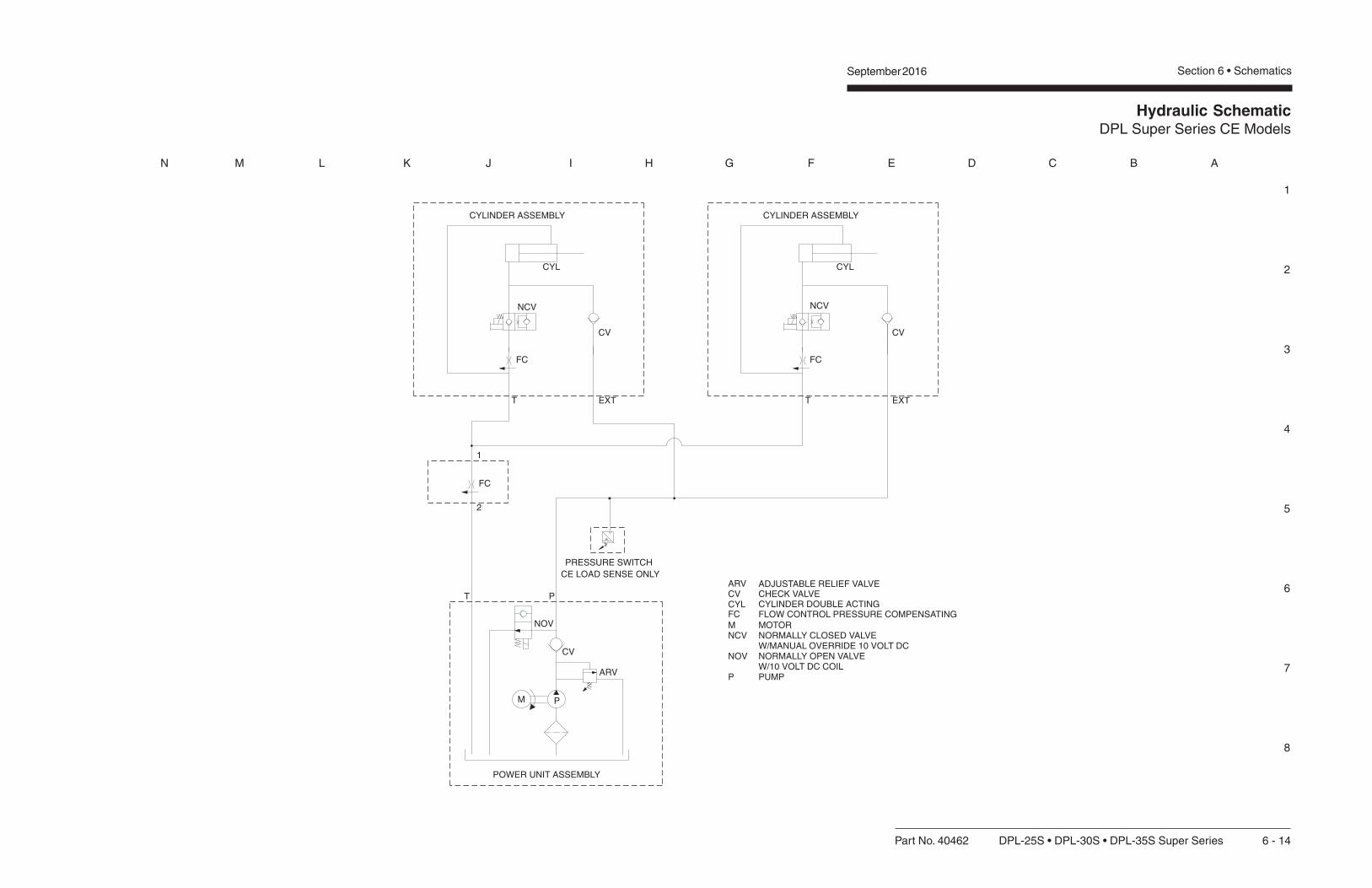
Hydraulic SchematicDPL Super Series CE Models
1
2
3
4
5
6
7
8
N M L K J I H G F E D C B A
September 2016 Section 6 • Schematics
Part No. 40462 DPL-25S • DPL-30S • DPL-35S Super Series 6 - 14

Hydraulic SchematicDPL Super Series CE Models
September 2016Section 6 • Schematics

Part No. 40462 DPL-25S • DPL-30S • DPL-35S Super Series 7 - 1
September 2016 Section 7 - Repair Procedures
Repair Procedures
About This SectionMost of the procedures in this section should onlybe performed by a trained service professionalin a suitably equipped workshop. Select theappropriate repair procedure after troubleshootingthe problem.
Perform disassembly procedures to the pointwhere repairs can be completed. Then tore-assemble, perform the disassembly steps inreverse order.
General Repair Process
Observe and Obey:
Repair procedures shall be completed by aperson trained and qualified on the repair of thismachine.
Immediately tag and remove from service adamaged or malfunctioning machine.
Repair any machine damage or malfunctionbefore operating the machine.
Before Repairs Start:
Read, understand and obey the safety rulesand operating instructions in the Genie DPLSuper Series Operator's Manual.
Be sure that all necessary tools and parts areavailable and ready for use.
Read each procedure completely and adhere tothe instructions. Attempting shortcuts mayproduce hazardous conditions.
Malfunctiondiscovered
Identifysymptoms
Troubleshoot
Performrepair
Return toservice problem
solved
problemstill exists
Inspectand test
Symbols Legend
Indicates the presence of a hazardthat will cause death or seriousinjury.
Indicates the presence of a hazardthat may cause death or seriousinjury.
Indicates the presence of a hazardthat will or may cause seriousinjury or damage to the machine.
Indicates special operation ormaintenance information.
Indicates that a specific result is expected afterperforming a series of steps.
7 - 2 DPL-25S • DPL-30S • DPL-35S Super Series Part No. 40462
September 2016Section 7 - Repair Procedures
1-2Base Components
How to Adjust the PlatformManual Lowering Cable1 Remove the base-end covers to access the
platform manual lowering cable.
2 Check to be sure:
Steer handle end:
• Actuator bracket is connected to the baseand the manual lowering valve
• Manual lowering cable is connected to thebase with two lock nuts
• Manual lowering cable is attached to theactuator bracket
Ladder end:
• Actuator bracket is connected to the baseand the manual lowering valve
• Manual lowering threaded rod is attachedto the actuator bracket
3 Adjust the manual lowering lever. Adjust thecable and the threaded rod at the lever. Be sureto maintain equal tension on the cable andthreaded rod.
Do not over-tighten the platformmanual lowering cable. Theplatform may not raise if there is tomuch tension on the cable.
Base Assembly
1-1Interlocks
The interlock contact brackets indicate properinstallation of the outriggers and only allow themachine to operate when the outriggers areproperly installed and adjusted.
How to Remove an InterlockContact Bracket1 Fully lower the platform, turn the machine off
and remove the key.
2 Store the outriggers in the storage sockets.
3 Trace the interlock contact bracket wires intothe junction box.
4 Label and disconnect the contact bracket wires.
5 Remove the interlock contact bracket mountingfasteners from the outrigger base socket.
6 Grasp the interlock contact bracket inside thebase outrigger socket and pull it out with thewires.

Part No. 40462 DPL-25S • DPL-30S • DPL-35S Super Series 7 - 3
September 2016 Section 7 - Repair Procedures
1-3How to Check the Resistance of aValve CoilThe valve coil is located at the bottom of thehydraulic lift cylinder.
1 Lower the platform, turn the machine off andremove the key.
2 Connect the leads from an ohmmeter to thevalve coil terminals.
Valve coil specifications
Solenoid operated N.C. valve, 10V 7.8 to 9.5 Ω
BASE ASSEMBLY
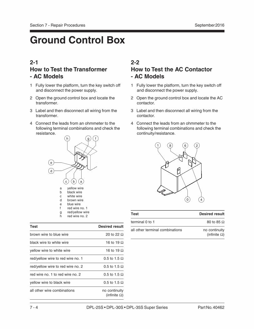
7 - 4 DPL-25S • DPL-30S • DPL-35S Super Series Part No. 40462
September 2016Section 7 - Repair Procedures
2-2How to Test the AC Contactor- AC Models1 Fully lower the platform, turn the key switch off
and disconnect the power supply.
2 Open the ground control box and locate the ACcontactor.
3 Label and then disconnect all wiring from thecontactor.
4 Connect the leads from an ohmmeter to thefollowing terminal combinations and check thecontinuity/resistance.
Test Desired result
terminal 0 to 1 80 to 85 Ω
all other terminal combinations no continuity
(infinite Ω)
21 8 6
40
Ground Control Box
2-1How to Test the Transformer- AC Models1 Fully lower the platform, turn the key switch off
and disconnect the power supply.
2 Open the ground control box and locate thetransformer.
3 Label and then disconnect all wiring from thetransformer.
4 Connect the leads from an ohmmeter to thefollowing terminal combinations and check theresistance.
a yellow wireb black wirec white wired brown wiree blue wiref red wire no. 1g red/yellow wireh red wire no. 2
d
c b a
h g f
Test Desired result
brown wire to blue wire 20 to 22 Ω
black wire to white wire 16 to 19 Ω
yellow wire to white wire 16 to 19 Ω
red/yellow wire to red wire no. 1 0.5 to 1.5 Ω
red/yellow wire to red wire no. 2 0.5 to 1.5 Ω
red wire no. 1 to red wire no. 2 0.5 to 1.5 Ω
yellow wire to black wire 0.5 to 1.5 Ω
all other wire combinations no continuity
(infinite Ω)
e
Part No. 40462 DPL-25S • DPL-30S • DPL-35S Super Series 7 - 5
September 2016 Section 7 - Repair Procedures
This page intentionally left blank.

7 - 6 DPL-25S • DPL-30S • DPL-35S Super Series Part No. 40462
September 2016Section 7 - Repair Procedures
Hydraulic Power Units
3-1Hydraulic Power Unit Components - AC ModelsIndexNo. Description Function
1 115-230V AC electric motor ............................. Single phase - 2850/3450 rpm, 50/60 Hz
2 Capacitor .......................................................... Motor start circuit
3 Pressure relief valve ......................................... Hydraulic relief valve adjustment
4 Solenoid operated N.O. dump valve ................ Diverts pump output back to reservoir during motor start up
5 10V DC coil ....................................................... Activates N.O. dump valve
6 Breather cap ..................................................... Reservoir vent
7 Sight gauge ...................................................... Hydraulic fluid level
8 Reservoir .......................................................... 1.3 gallons (4.9 liters)
9 Pipe plug ........................................................... Drains reservoir
10 Pick-up filter ...................................................... Filters hydraulic fluid
11 O-ring ................................................................ Seals reservoir
12 Check valve ...................................................... One-way valve for pump output
13 Pump ................................................................ 0.5 to 0.6 gallons per minute at 2000 psi1.89 to 2.27 liters per minute at 138 bar
14 Motor seal ......................................................... Seals motor from contaminants
15 Motor bearing ................................................... Aligns motor shaft into pump
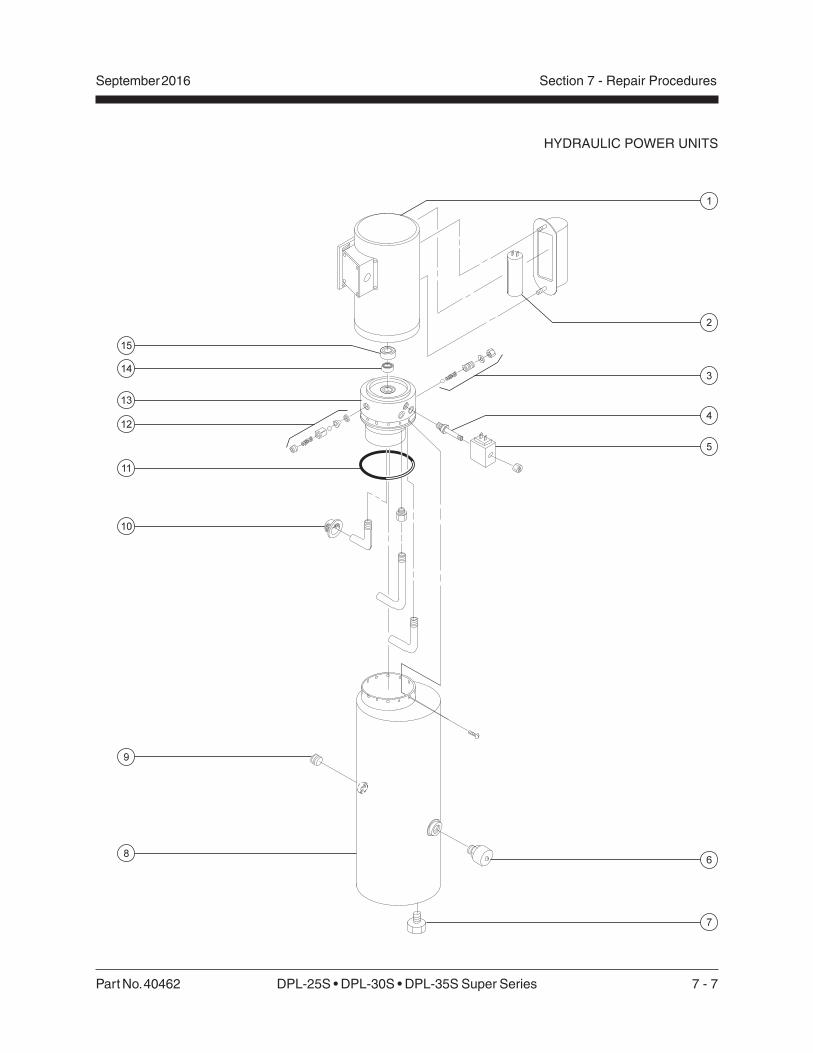
Part No. 40462 DPL-25S • DPL-30S • DPL-35S Super Series 7 - 7
September 2016 Section 7 - Repair Procedures
HYDRAULIC POWER UNITS

7 - 8 DPL-25S • DPL-30S • DPL-35S Super Series Part No. 40462
September 2016Section 7 - Repair Procedures
HYDRAULIC POWER UNITS
3-2Hydraulic Power Unit Components - DC ModelsIndexNo. Description Function
1 12V DC electric motor ...................................... 12V DC standard duty 1 terminal180 amp at 2650 psi (183 bar)
2 Electric motor starter solenoid .......................... Relay connecting power supply to electric motor
3 Pressure relief valve ......................................... Hydraulic relief valve adjustment
4 Solenoid operated N.O. dump valve ................ Diverts pump output back to reservoir during motor start up
5 10V DC coil ....................................................... Activates N.O. dump valve
6 Breather cap ..................................................... Reservoir vent
7 Sight gauge ...................................................... Hydraulic fluid level
8 Reservoir .......................................................... 1.3 gallons (4.9 liters)
9 Pipe plug ........................................................... Drains reservoir
10 Pick-up filter ...................................................... Filters hydraulic fluid
11 O-ring ................................................................ Seals reservoir
12 Check valve ...................................................... One way valve for pump output
13 Pump ................................................................ 0.7 to 1 gallons per minute at 2000 psi2.6 to 3.76 liters per minute at 138 bar
14 Motor seal ......................................................... Seals motor from contaminants
15 Motor bearing ................................................... Aligns motor shaft into pump

Part No. 40462 DPL-25S • DPL-30S • DPL-35S Super Series 7 - 9
September 2016 Section 7 - Repair Procedures
HYDRAULIC POWER UNITS

7 - 10 DPL-25S • DPL-30S • DPL-35S Super Series Part No. 40462
September 2016Section 7 - Repair Procedures
3-3How to Remove the HydraulicPower Unit - AC Models1 Fully lower the platform, turn the machine off,
remove the key and disconnect the powersource.
2 Remove the base cover from the power unit.
3 Tag, disconnect and plug the hydraulic hoses.Cap the fittings on the power unit.
Bodily injury hazard. Sprayinghydraulic oil can penetrate andburn skin. Loosen hydraulicconnections very slowly to allowthe oil pressure to dissipategradually. Do not allow oil to squirtor spray.
4 Tag and disconnect the electrical wiring fromthe valve coil.
Electrocution/burn hazard. Contactwith electrically charged circuitsmay result in death or seriousinjury. Remove all rings, watchesand other jewelry.
5 Support the hydraulic power unit with a liftingdevice.
6 Remove the power unit mounting fasteners.
7 Remove the cover from the junction box on themotor. Then tag and disconnect the electricalwiring in the junction box. Loosen the squeezeconnector on the junction box and pull thewiring out through the squeeze connector.
8 Remove the power unit from the machine
Crushing hazard. The power unitwill fall unless it is properlysupported.
Note: If a new power unit is installed, the pressurerelief valve must be properly adjusted. See 3-6,How to Adjust the Pressure Relief Valve.
HYDRAULIC POWER UNITS
3-4How to Remove the HydraulicPower Unit - DC Models1 Fully lower the platform, turn the machine off,
remove the key and disconnect the powersource.
2 Remove the base cover from the power unit.
3 Tag, disconnect and plug the hydraulic hoses.Cap the fittings on the power unit.
Bodily injury hazard. Sprayinghydraulic oil can penetrate andburn skin. Loosen hydraulicconnections very slowly to allowthe oil pressure to dissipategradually. Do not allow oil to squirtor spray.
4 Tag and disconnect the electrical wiring fromthe valve coil.
Electrocution hazard. Contact withelectrically charged circuits mayresult in death or serious injury.Remove all rings, watches andother jewelry.
5 Tag and disconnect the electrical wiring fromthe motor start solenoid.
6 Support the hydraulic power unit with a liftingdevice.
7 Remove the power unit mounting fasteners,then remove the power unit from the machine.
Crushing hazard. The power unitwill fall unless it is properlysupported.
Note: If a new power unit is installed, the pressurerelief valve must be properly adjusted. See 3-6,How to Adjust the Pressure Relief Valve.
Part No. 40462 DPL-25S • DPL-30S • DPL-35S Super Series 7 - 11
September 2016 Section 7 - Repair Procedures
HYDRAULIC POWER UNITS
3-5How to Remove the HydraulicPump1 Fully lower the platform, turn the machine off
and remove the key.
2 Remove the base cover from the power unit.
3 Remove the drain plug from the hydraulicreservoir and completely drain the reservoir intoa container. Properly discard of oil.
5 Remove the power unit. See 3-3, How toRemove the Power Unit - AC Models or 3-4,How to Remove the Power Unit - DC Models.
6 Support the hydraulic reservoir with a liftingdevice.
7 Remove the mounting fasteners from thereservoir. Then remove the reservoir from thepower unit.
Note: It may be necessary to tap the side of thereservoir with a soft rubber mallet to loosen it.
8 Remove the mounting fasteners from the pump.Then remove the pump from the power unit.
When installing the reservoir, besure not to damage the o-ring.
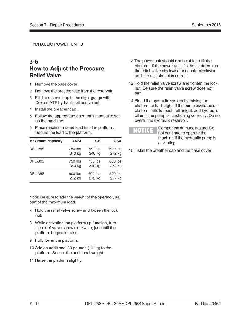
7 - 12 DPL-25S • DPL-30S • DPL-35S Super Series Part No. 40462
September 2016Section 7 - Repair Procedures
HYDRAULIC POWER UNITS
12 The power unit should not be able to lift theplatform. If the power unit lifts the platform, turnthe relief valve clockwise or counterclockwiseuntil the adjustment is correct.
13 Hold the relief valve screw and tighten the locknut. Be sure the relief valve screw does notturn.
14 Bleed the hydraulic system by raising theplatform to full height. If the pump cavitates orplatform fails to reach full height, add hydraulicoil until the pump is functioning correctly. Do notoverfill the hydraulic reservoir.
Component damage hazard. Donot continue to operate themachine if the hydraulic pump iscavitating.
15 Install the breather cap and the base cover.
3-6How to Adjust the PressureRelief Valve1 Remove the base cover.
2 Remove the breather cap from the reservoir.
3 Fill the reservoir up to the sight gauge withDexron ATF hydraulic oil equivalent.
4 Install the breather cap.
5 Follow the appropriate operator's manual to setup the machine.
6 Place maximum rated load into the platform.Secure the load to the platform.
Maximum capacity ANSI CE CSA
DPL-25S 750 lbs 750 lbs 600 lbs
340 kg 340 kg 272 kg
DPL-30S 750 lbs 750 lbs 600 lbs
340 kg 340 kg 272 kg
DPL-35S 600 lbs 600 lbs 500 lbs
272 kg 272 kg 227 kg
Note: Be sure to add the weight of the operator, aspart of the maximum load.
7 Hold the relief valve screw and loosen the locknut.
8 While activating the platform up function, turnthe relief valve screw clockwise, just until theplatform begins to raise.
9 Fully lower the platform.
10 Add an additional 30 pounds (14 kg) to theplatform. Secure the additional weight.
11 Raise the platform slightly.

Part No. 40462 DPL-25S • DPL-30S • DPL-35S Super Series 7 - 13
September 2016 Section 7 - Repair Procedures
3-7How to Check the Resistanceof a Valve Coil1 Fully lower the platform, turn the machine off
and remove the key.
2 Connect the leads from an ohmmeter to thevalve coil terminals.
Valve coil specifications
Solenoid operated N.O. valve, 10V 5.9 to 7.2 Ω
Lowering valve, 10V 7.8 to 9.5 Ω(located at base of cylinder)
3-8How to Test the Motor StartSolenoid - DC Models
Electrocution/burn hazard. Contactwith electrically charged circuitsmay result in death or seriousinjury. Remove all rings, watchesand other jewelry.
Electrocution/burn hazard.Disconnect the ground cable fromthe battery before performing thisprocedure.
1 Label and disconnect all the wiring from themotor start solenoid.
2 Connect the leads from an ohmmeter to eachterminal combination and check for continuity.
Test Desired result
Small post to ground 13 to 17 Ω
2 large posts no continuity
(infinite Ω)
Small post to no continuity
any large post (infinite Ω)
aa b
3 Connect 12V DC to the small post and a groundwire to the case of the solenoid, then test thefollowing terminal combinations.
Test Desired result
2 large posts continuity (zero Ω)
a high amp power contact terminal(large post)
b solenoid activate coil terminal(small post)
HYDRAULIC POWER UNITS

7 - 14 DPL-25S • DPL-30S • DPL-35S Super Series Part No. 40462
September 2016Section 7 - Repair Procedures
Mast Assembly
Mast Componentsa number 4 column idler wheel assemblyb number 3 column idler wheel assemblyc number 2 column idler wheel assemblyd number 1 columne number 2 columnf number 3 column
g number 4 columnh carriagei number 5 columnj number 5 column idler wheel assemblyk number 6 column idler wheel assemblyl number 6 column
DPL-25S
DPL-30S DPL-35S
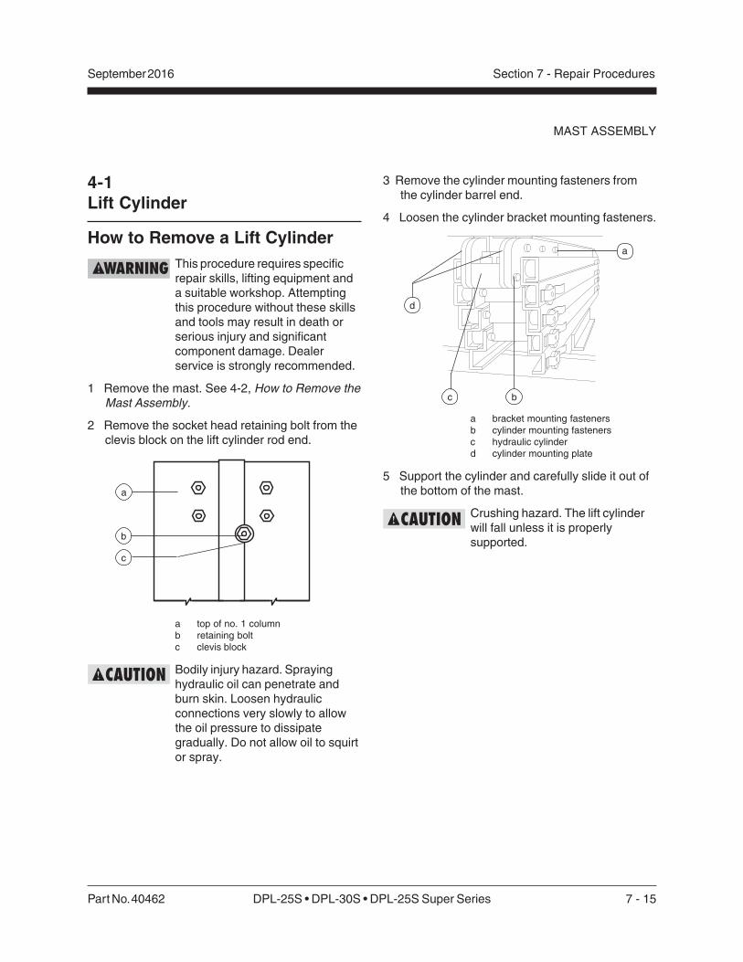
Part No. 40462 DPL-25S • DPL-30S • DPL-25S Super Series 7 - 15
September 2016 Section 7 - Repair Procedures
4-1Lift Cylinder
How to Remove a Lift CylinderThis procedure requires specificrepair skills, lifting equipment anda suitable workshop. Attemptingthis procedure without these skillsand tools may result in death orserious injury and significantcomponent damage. Dealerservice is strongly recommended.
1 Remove the mast. See 4-2, How to Remove theMast Assembly.
2 Remove the socket head retaining bolt from theclevis block on the lift cylinder rod end.
a top of no. 1 columnb retaining boltc clevis block
Bodily injury hazard. Sprayinghydraulic oil can penetrate andburn skin. Loosen hydraulicconnections very slowly to allowthe oil pressure to dissipategradually. Do not allow oil to squirtor spray.
a
b
c
MAST ASSEMBLY
3 Remove the cylinder mounting fasteners fromthe cylinder barrel end.
4 Loosen the cylinder bracket mounting fasteners.
a bracket mounting fastenersb cylinder mounting fastenersc hydraulic cylinderd cylinder mounting plate
5 Support the cylinder and carefully slide it out ofthe bottom of the mast.
Crushing hazard. The lift cylinderwill fall unless it is properlysupported.
a
b
d
c
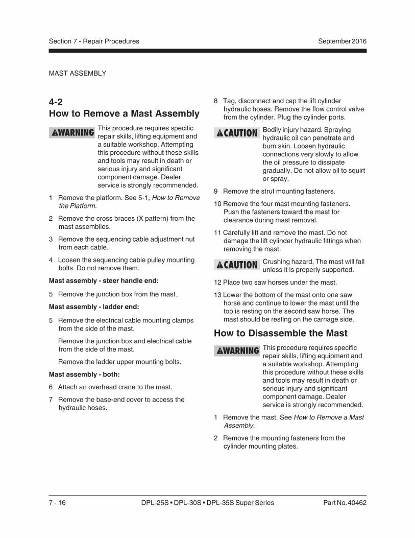
7 - 16 DPL-25S • DPL-30S • DPL-35S Super Series Part No. 40462
September 2016Section 7 - Repair Procedures
8 Tag, disconnect and cap the lift cylinderhydraulic hoses. Remove the flow control valvefrom the cylinder. Plug the cylinder ports.
Bodily injury hazard. Sprayinghydraulic oil can penetrate andburn skin. Loosen hydraulicconnections very slowly to allowthe oil pressure to dissipategradually. Do not allow oil to squirtor spray.
9 Remove the strut mounting fasteners.
10 Remove the four mast mounting fasteners.Push the fasteners toward the mast forclearance during mast removal.
11 Carefully lift and remove the mast. Do notdamage the lift cylinder hydraulic fittings whenremoving the mast.
Crushing hazard. The mast will fallunless it is properly supported.
12 Place two saw horses under the mast.
13 Lower the bottom of the mast onto one sawhorse and continue to lower the mast until thetop is resting on the second saw horse. Themast should be resting on the carriage side.
How to Disassemble the MastThis procedure requires specificrepair skills, lifting equipment anda suitable workshop. Attemptingthis procedure without these skillsand tools may result in death orserious injury and significantcomponent damage. Dealerservice is strongly recommended.
1 Remove the mast. See How to Remove a MastAssembly.
2 Remove the mounting fasteners from thecylinder mounting plates.
MAST ASSEMBLY
4-2How to Remove a Mast Assembly
This procedure requires specificrepair skills, lifting equipment anda suitable workshop. Attemptingthis procedure without these skillsand tools may result in death orserious injury and significantcomponent damage. Dealerservice is strongly recommended.
1 Remove the platform. See 5-1, How to Removethe Platform.
2 Remove the cross braces (X pattern) from themast assemblies.
3 Remove the sequencing cable adjustment nutfrom each cable.
4 Loosen the sequencing cable pulley mountingbolts. Do not remove them.
Mast assembly - steer handle end:
5 Remove the junction box from the mast.
Mast assembly - ladder end:
5 Remove the electrical cable mounting clampsfrom the side of the mast.
Remove the junction box and electrical cablefrom the side of the mast.
Remove the ladder upper mounting bolts.
Mast assembly - both:
6 Attach an overhead crane to the mast.
7 Remove the base-end cover to access thehydraulic hoses.
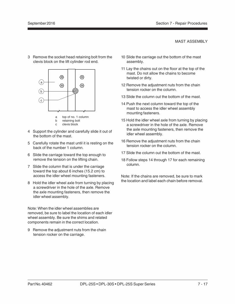
Part No. 40462 DPL-25S • DPL-30S • DPL-25S Super Series 7 - 17
September 2016 Section 7 - Repair Procedures
3 Remove the socket head retaining bolt from theclevis block on the lift cylinder rod end.
a top of no. 1 columnb retaining boltc clevis block
4 Support the cylinder and carefully slide it out ofthe bottom of the mast.
5 Carefully rotate the mast until it is resting on theback of the number 1 column.
6 Slide the carriage toward the top enough toremove the tension on the lifting chain.
7 Slide the column that is under the carriagetoward the top about 6 inches (15.2 cm) toaccess the idler wheel mounting fasteners.
8 Hold the idler wheel axle from turning by placinga screwdriver in the hole of the axle. Removethe axle mounting fasteners, then remove theidler wheel assembly.
Note: When the idler wheel assemblies areremoved, be sure to label the location of each idlerwheel assembly. Be sure the shims and relatedcomponents remain in the correct location.
9 Remove the adjustment nuts from the chaintension rocker on the carriage.
MAST ASSEMBLY
a
b
c
10 Slide the carriage out the bottom of the mastassembly.
11 Lay the chains out on the floor at the top of themast. Do not allow the chains to becometwisted or dirty.
12 Remove the adjustment nuts from the chaintension rocker on the column.
13 Slide the column out the bottom of the mast.
14 Push the next column toward the top of themast to access the idler wheel assemblymounting fasteners.
15 Hold the idler wheel axle from turning by placinga screwdriver in the hole of the axle. Removethe axle mounting fasteners, then remove theidler wheel assembly.
16 Remove the adjustment nuts from the chaintension rocker on the column.
17 Slide the column out the bottom of the mast.
18 Follow steps 14 through 17 for each remainingcolumn.
Note: If the chains are removed, be sure to markthe location and label each chain before removal.
7 - 18 DPL-25S • DPL-30S • DPL-35S Super Series Part No. 40462
September 2016Section 7 - Repair Procedures
13 After all the columns are together the idler wheelassemblies need to be installed.
14 Remove the tension from the lifting chains onthe number 2 column by pushing the number 3column toward the top of the mast.
15 Install the idler wheel assembly into the top ofthe number 2 column. Tighten the mountingfasteners.
Note: Be sure all idler wheels rotate with noexcessive side to side movement and be sure thatthey do not rub on the inside of the column.Replace worn shims if necessary.
16 Follow steps 14 and 15 for each remaining idlerwheel assembly.
17 Be sure that all of the idler wheel axle mountingfasteners are flush with the column.
Component damage hazard. Theroller wheels will becomedamaged if the idler wheel axlemounting fasteners are not flushwith the column.
18 Reassemble the machine. Then adjust the liftingchains. See 4-3, How to Adjust the LiftingChains.
MAST ASSEMBLY
How to Assemble the MastThis procedure requires specificrepair skills, lifting equipment anda suitable workshop. Attemptingthis procedure without these skillsand tools may result in death orserious injury and significantcomponent damage. Dealerservice is strongly recommended.
1 Thoroughly clean all columns.
2 Secure the number 1 column to the saw horsesand lay the chains out on the floor at the top.
3 Apply a generous amount of Boe-lube wax(Genie part number 90337) to the inside andoutside channels of each column.
4 Slide the number 2 column into the number 1column.
5 Lay the number 2 column chains onto the floor.Do not allow the chains to become twisted ordirty.
6 Pick up the number 1 column chains and laythem inside the number 2 column.
7 Slide the number 3 column into the number 2column.
8 When the column is almost all the way in, guidethe number 1 column chains into the chaintension rocker on the number 3 column.
9 Install the adjustment nuts onto the number 1column chains. Adjust the adjustment nuts sothe lifting chains have equal tension and thechain tension rocker is centered in theinspection hole in the column.
10 Lay the number 3 column chains on the floor.Do not allow the chains to become twisted ordirty.
11 Pick up the number 2 column chains and laythem inside the number 3 column.
12 Follow steps 4 through 11 for each remainingcolumn and the carriage.

Part No. 40462 DPL-25S • DPL-30S • DPL-25S Super Series 7 - 19
September 2016 Section 7 - Repair Procedures
MAST ASSEMBLY
4-3How to Adjust the Lifting ChainsWhen adjusting the lifting chains, it is veryimportant to maintain equal adjustment for bothmast assemblies.
1 Fully lower the machine and check to see if allthe columns (except the carriage) are even atthe top. The chains are adjusted correctly if allthe columns are even at the top.
To adjust column chains:
2 Mark the column to be adjusted.
3 Raise the platform 6 feet (2 m).
4 Turn the adjustment lock nuts evenly on bothchain terminals clockwise to raise the column orcounterclockwise to lower the column.
5 Fully lower the machine and recheck thealignment of the columns. Re-adjust ifnecessary.
6 Check to make sure the chain terminals oneach column have equal tension and the locknuts are tight.
4-4How to Adjust the Glide PadsWhen adjusting the glide pads, it is very importantto maintain equal adjustment for both mastassemblies.
1 Fully lower the platform, turn off the machineand remove the key.
2 Locate the upper and lower glide pad boltsbelow each top roller wheel bolt on both sidesof the columns.
3 Hold each glide pad bolt and loosen the lock nuton all the glide pads.
4 Turn all the glide pad bolts clockwise until theglide pads make contact with the column.Adjust both sides of the mast. Be sure the sidesof the columns are within 1/8 inch(3.175 mm) to even with each other.
5 Starting at the number 1 column, torque theupper and lower glide pad bolts to 12 in-lbs(1.356 Nm). Hold the glide pad bolt and tightenthe lock nut. Be sure the glide pad bolt does notturn.
6 Repeat step 5 for each remaining upper andlower glide pad bolt on one side of the mast.Start at the number 1 column and adjust eachcolumn, working toward the carriage.
7 Repeat step 5 for all of the upper and lowerglide pad bolts on the other side of the mast.
Note: Make sure glide pad bolts are adjustedevenly on each side to maintain squareness of thecolumns.
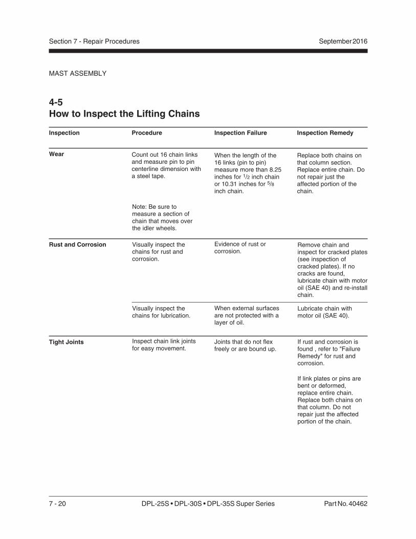
7 - 20 DPL-25S • DPL-30S • DPL-35S Super Series Part No. 40462
September 2016Section 7 - Repair Procedures
MAST ASSEMBLY
4-5How to Inspect the Lifting Chains
Inspection Failure
When the length of the16 links (pin to pin)measure more than 8.25inches for 1/2 inch chainor 10.31 inches for 5/8inch chain.
Inspection Remedy
Replace both chains onthat column section.Replace entire chain. Donot repair just theaffected portion of thechain.
Procedure
Count out 16 chain linksand measure pin to pincenterline dimension witha steel tape.
Note: Be sure tomeasure a section ofchain that moves overthe idler wheels.
Visually inspect thechains for rust andcorrosion.
Visually inspect thechains for lubrication.
Inspect chain link jointsfor easy movement.
Evidence of rust orcorrosion.
When external surfacesare not protected with alayer of oil.
Joints that do not flexfreely or are bound up.
Remove chain andinspect for cracked plates(see inspection ofcracked plates). If nocracks are found,lubricate chain with motoroil (SAE 40) and re-installchain.
Lubricate chain withmotor oil (SAE 40).
If rust and corrosion isfound , refer to "FailureRemedy" for rust andcorrosion.
If link plates or pins arebent or deformed,replace entire chain.Replace both chains onthat column. Do notrepair just the affectedportion of the chain.
Inspection
Wear
Rust and Corrosion
Tight Joints

Part No. 40462 DPL-25S • DPL-30S • DPL-25S Super Series 7 - 21
September 2016 Section 7 - Repair Procedures
Inspection Failure
Raised pins.
Procedure
Visually inspect for raisedpins.
MAST ASSEMBLY
Inspection Remedy
Replace both chains onthat column section. Donot repair just theaffected portion of thechain.
Replace both chains onthat column section. Donot repair just theaffected portion of thechain.
Replace both chains onthat column section. Donot repair just theaffected portion of thechain.
Check alignment of chainanchors and idler wheels.
Visually inspect for turnedpins by insuring all theflats on the "V" heads arealigned.
Visually inspect for wearpatterns on heads of linkpins and outside linkplates where they contactthe idler wheel.
Misalignment of flats onall "V" heads.
Wear on pin heads ornoticeable wear in theprofile of the outside linkplate.
link plate wear
Visually inspect chainterminals.
Broken chainterminals fingers.
Replace chain terminal.
Bent or damaged terminal. Replace chain terminal.
Twisted or misalignedchain terminal.
Re-align chain terminal toensure even loading ofchain.
Threaded rod not visiblein inspection hole.
Replace chain terminaland threaded rod.
Visually inspect chain idlerwheels.
Idler wheels have badlyworn flanges.
Replace idler wheel andcheck chain alignment.
Idler wheels havegrooves worn into chaincontact surface.
Replace idlerwheel.idler
wheel
chainterminals
Visually inspect chain linkplates for cracks.
Cracks in any chain linkplate.
Replace both chains onthat column section.Replace entire chain. Donot repair just the affectedportion of the chain.
threadedrod
Inspection
Raised or Turned Pins
Chain Side
Chain Terminals
Idler Wheels
Cracked Link Plates
7 - 22 DPL-25S • DPL-30S • DPL-35S Super Series Part No. 40462
September 2016Section 7 - Repair Procedures
5-1How to Remove the Platform1 Remove the cover from the platform control box
and the AC outlet to access the mountingscrews.
2 Remove the control box and AC outlet.
3 Remove the platform control cable clamps fromthe platform.
4 Rotate the platform guard rails to the uprightposition. Close and latch the platform entry gateand the platform end guard rail.
5 Attach an overhead crane or similar liftingdevice to the platform.
6 Remove the platform mounting fasteners.
7 Remove the platform from the machine.
Crushing Hazard. The platform willfall if it is not properly supportedwith the overhead crane.
If a platform is being replaced, besure that all appropriate safety andinstructional decals are applied tothe new platform.
Platform
5-2Platform Control Box
How to Test the Contactors1 Fully lower the platform, turn the key switch off
and disconnect the power supply.
2 Loosen the platform control box lid fastenersand open the control box.
3 Observe the markings on the contactor to bechecked. The N.O. marking designates theswitch as normally open and N.C. designatesthe switch as normally closed.
4 Connect a continuity tester to the exposedscrew terminals.
Result: Normally open contactors should haveno continuity. Normally closed contactorsshould have full continuity.
5 Push the small triangular button on the top ofthe contactor and check the continuity.
Result: Normally open contactors should havefull continuity. Normally closed contactorsshould have no continuity.

Part No. 40462 DPL-25S • DPL-30S • DPL-25S Super Series 7 - 23
September 2016 Section 7 - Repair Procedures
PLATFORM
How to Test Power-to-PlatformGFCI outlet1 Fully lower the platform, turn the key switch off.
2 AC and DC models: Be sure the AC powersupply is properly connected.
3 Connect an AC voltage tester or a small handtool to the platform GFCI receptacle.
4 Test the voltage or test the hand tool operation.
Result: The voltage should be 115V AC nominal
or the hand tool should operate normally.
5 Push the black TEST button on the GFCIreceptacle.
Result: The voltage should be 0V or the hand
tool should not operate.
6 Push the red RESET button on the GFCIreceptacle.
Result: The voltage should be 115V AC nominal
or the hand tool should operate normally.

7 - 24 DPL-25S • DPL-30S • DPL-35S Super Series Part No. 40462
September 2016Section 7 - Repair Procedures
This page intentionally left blank.


![[4] - DPL Homes](https://img.pdfslide.us/doc/110x75/6178ed8e7b08394ecd4e312d/4-dpl-homes.jpg)