Embed Size (px)
Citation preview
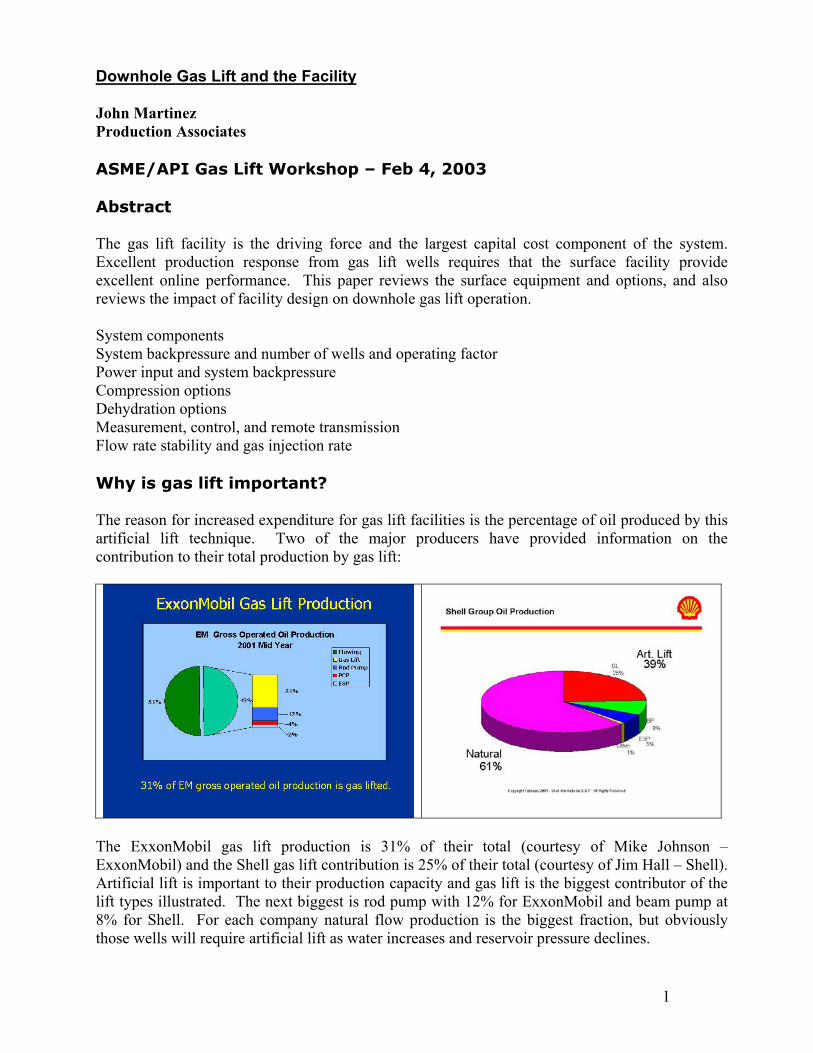
Downhole Gas Lift and the Facility John Martinez Production Associates ASME/API Gas Lift Workshop – Feb 4, 2003 Abstract The gas lift facility is the driving force and the largest capital cost component of the system. Excellent production response from gas lift wells requires that the surface facility provide excellent online performance. This paper reviews the surface equipment and options, and also reviews the impact of facility design on downhole gas lift operation. System components System backpressure and number of wells and operating factor Power input and system backpressure Compression options Dehydration options Measurement, control, and remote transmission Flow rate stability and gas injection rate Why is gas lift important? The reason for increased expenditure for gas lift facilities is the percentage of oil produced by this artificial lift technique. Two of the major producers have provided information on the contribution to their total production by gas lift:
The ExxonMobil gas lift production is 31% of their total (courtesy of Mike Johnson – ExxonMobil) and the Shell gas lift contribution is 25% of their total (courtesy of Jim Hall – Shell). Artificial lift is important to their production capacity and gas lift is the biggest contributor of the lift types illustrated. The next biggest is rod pump with 12% for ExxonMobil and beam pump at 8% for Shell. For each company natural flow production is the biggest fraction, but obviously those wells will require artificial lift as water increases and reservoir pressure declines.
1
Downhole Gas Lift and the Facility
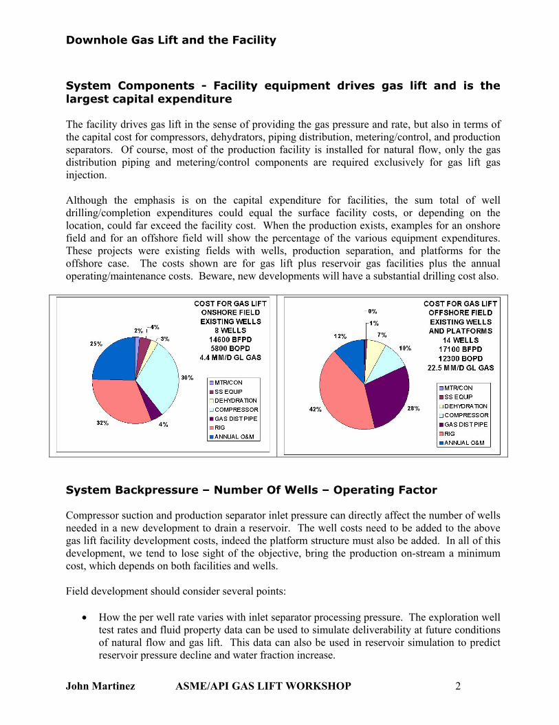
System Components - Facility equipment drives gas lift and is the largest capital expenditure The facility drives gas lift in the sense of providing the gas pressure and rate, but also in terms of the capital cost for compressors, dehydrators, piping distribution, metering/control, and production separators. Of course, most of the production facility is installed for natural flow, only the gas distribution piping and metering/control components are required exclusively for gas lift gas injection. Although the emphasis is on the capital expenditure for facilities, the sum total of well drilling/completion expenditures could equal the surface facility costs, or depending on the location, could far exceed the facility cost. When the production exists, examples for an onshore field and for an offshore field will show the percentage of the various equipment expenditures. These projects were existing fields with wells, production separation, and platforms for the offshore case. The costs shown are for gas lift plus reservoir gas facilities plus the annual operating/maintenance costs. Beware, new developments will have a substantial drilling cost also.
System Backpressure – Number Of Wells – Operating Factor Compressor suction and production separator inlet pressure can directly affect the number of wells needed in a new development to drain a reservoir. The well costs need to be added to the above gas lift facility development costs, indeed the platform structure must also be added. In all of this development, we tend to lose sight of the objective, bring the production on-stream a minimum cost, which depends on both facilities and wells. Field development should consider several points:
• How the per well rate varies with inlet separator processing pressure. The exploration well test rates and fluid property data can be used to simulate deliverability at future conditions of natural flow and gas lift. This data can also be used in reservoir simulation to predict reservoir pressure decline and water fraction increase.
John Martinez ASME/API GAS LIFT WORKSHOP 2

Downhole Gas Lift and the Facility
• What the operating factor (on-line time) is for natural flow and for gas lift, or for other potential operating conditions. This data should be based on down time tabulation at similar operating facilities.
• How many wells would be required as the reservoir declines, based on delivery simulation and on reservoir simulation.
The combination of reservoir and delivery simulation provides a production graph of gross rate (oil plus water) versus separator pressure on the inlet vessel. As pressure declines and water fraction increases, the initial natural flow becomes gas lift to reduce the wells needed for production. The field development summary is: RESERVOIR PRESSURE
Psig & Water %
TARGET FIELD
OIL RATE stb/d
OPERATING FACTOR
DAILY OIL
REQUIRED stb/d
OIL RATE PER WELL
stb/d @200 psig
INLET
WELL COUNT
@200 psig
INLET
OIL RATE PER WELL
stb/d @50 psig INLET
WELL COUNT
@50 psig INLET
2400 @ 0% 100,000 0.93 107,530 2000 54 2200 49
2000 @ 25% 90,000 0.86 104,650 1050 100 1180 89
1600 @ 50% 50,000 0.83 60,240 200 302 450 134
The well count increases substantially as the reservoir declines, however the low inlet pressure can reduce the well count. At $2 million per offshore well, the savings due to low pressure is great, especially at the depleted future condition. In addition to saving capital expenditure for wells, the low suction pressure can reduce compression horsepower required.
John Martinez ASME/API GAS LIFT WORKSHOP 3

Downhole Gas Lift and the Facility
Power Input and System Backpressure - Compressor suction and discharge pressure effects The graph of production rate versus injection gas-liquid ratio has curves for several depths of injection, each corresponding to an available injection pressure (chart from API RP 11V8). The deeper injection point yields a higher rate for each well (PI = 10 and PI = 1). The ability to maintain high pressure and steady rate, not affected by the temperatures noted in the section on compressor options, can give significant production increase or keep production on target. Thus a key objective in gas lift is to keep the injection pressure high and design the set pressures on the valves to correspond to high pressure. The other part of the picture is the suction pressure and its effect on production. Similar graphs, one for each well (Well 1 PI = 10, Well 2 PI = 1), show that lower suction pressure increases production rate over the range of injection gas-liquid ratio.
From the combination of suction pressure data, discharge pressure data, and compressor brake horsepower per million scf/d of gas lift gas, comes an optimization curve (also from API 11V8) of power per barrel of lifted fluid for a range of suction pressures, again for the higher PI well and for the lower PI well. Approximately 50 psig suction pressure appears optimum for each case, and this low pressure can drastically reduce the number of wells in a new development.
John Martinez ASME/API GAS LIFT WORKSHOP 4
Downhole Gas Lift and the Facility
Compression Options Compression is the biggest facility component and the most important for steady pressure and rate. Operating time on-line should exceed 99% and the design should include points that can cause the compressor or driver to deliver less than expected:
• Water vapor in the gas should be included in the process simulation for capacity and horsepower required. Water vapor increases the horsepower required and also increases heat duty for cooling after compression. The machine or cooler capacity becomes inadequate during the hot part of the day or during the summer months.
• Average temperature is used for design, but actual temperature in hottest part of the day could decrease engine or turbine horsepower output as well as the cooler heat exchange capacity. When gas rate is decreased to the gas lift system, oil production decreases and does not necessarily resume when the ambient temperature cools.
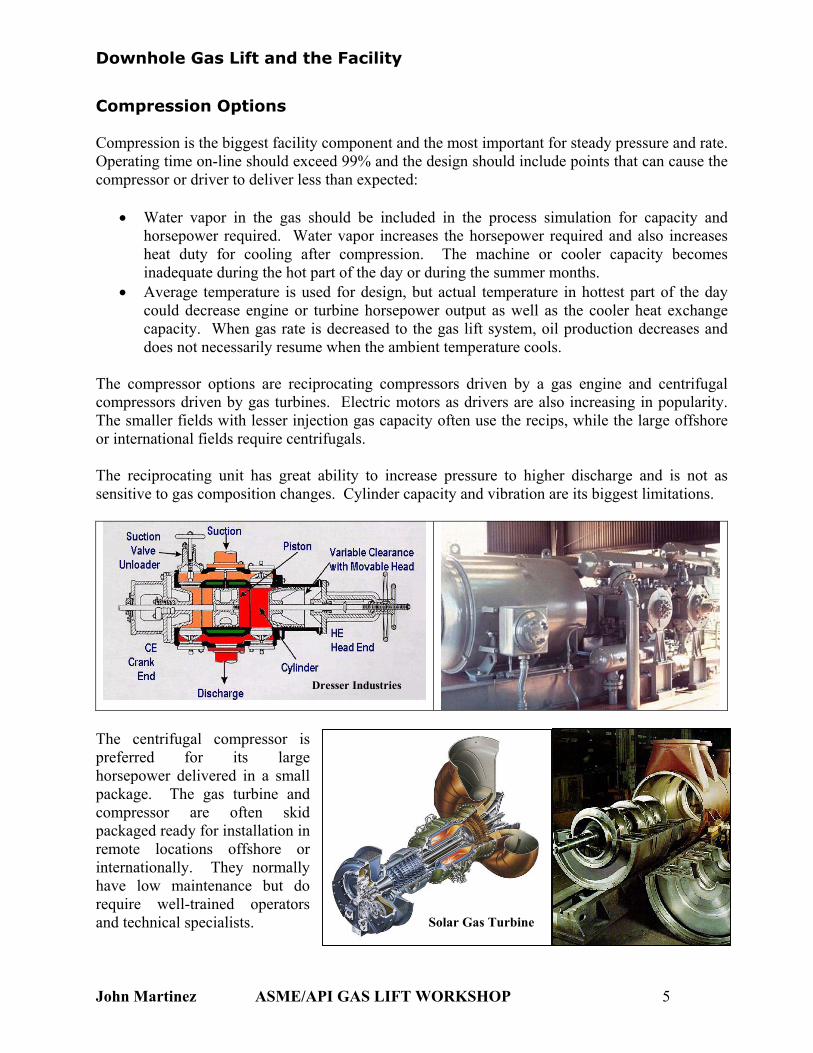
The compressor options are reciprocating compressors driven by a gas engine and centrifugal compressors driven by gas turbines. Electric motors as drivers are also increasing in popularity. The smaller fields with lesser injection gas capacity often use the recips, while the large offshore or international fields require centrifugals. The reciprocating unit has great ability to increase pressure to higher discharge and is not as sensitive to gas composition changes. Cylinder capacity and vibration are its biggest limitations.
Dresser Industries
The centrifugal compressor preferred for its larghorsepower delivered in a smapackage. The gas turbine ancompressor are often skpackaged ready for installation remote locations offshore internationally. They normalhave low maintenance but drequire well-trained operatoand technical specialists.
John Martinez ASME
is e ll d
id in or ly o rs
/API GAS LIFT W
Solar Gas Turbine
ORKSHOP 5
Downhole Gas Lift and the Facility
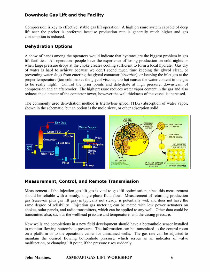
Compression is key to effective, stable gas lift operation. A high pressure system capable of deep lift near the packer is preferred because production rate is generally much higher and gas consumption is reduced. Dehydration Options A show of hands among the operators would indicate that hydrates are the biggest problem in gas lift facilities. All operations people have the experience of losing production on cold nights or when large pressure drops at the choke creates cooling sufficient to form a local hydrate. Gas dry of water is hard to achieve because we don’t spend much time keeping the glycol clean, or preventing water slugs from entering the glycol contactor (absorber), or keeping the inlet gas at the proper temperature (too cold makes the glycol viscous, too hot causes the water content in the gas to be really high). Control the prior points and dehydrate at high pressure, downsteam of compression and an aftercooler. The high pressure reduces water vapor content in the gas and also reduces the diameter of the contactor tower, however the wall thickness of the vessel is increased. The commonly used dehydration method is triethylene glycol (TEG) absorption of water vapor, shown in the schematic, but an option is the mole sieve, or other adsorption solid.
Measurement, Control, and Remote Transmission Measurement of the injection gas lift gas is vital to gas lift optimization, since this measurement should be reliable with a steady, single-phase fluid flow. Measurement of returning production gas (reservoir plus gas lift gas) is typically not steady, is potentially wet, and does not have the same degree of reliability. Injection gas metering can be mated with low power actuators on chokes, solar panels, and radio transmitters, which can be applied to any well. Other data could be transmitted also, such as the wellhead pressure and temperature, and the casing pressure. New wells and completions in a new field development should have a bottomhole sensor installed to monitor flowing bottomhole pressure. The information can be transmitted to the control room on a platform or to the operations center for unmanned wells. The gas rate can be adjusted to maintain the desired flowing bottomhole pressure, which serves as an indicator of valve malfunction, or changing lift point, if the pressure rises suddenly.
John Martinez ASME/API GAS LIFT WORKSHOP 6
Downhole Gas Lift and the Facility
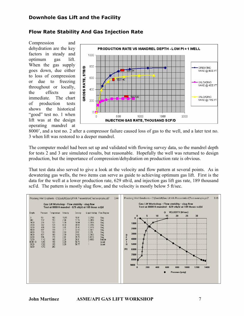
Flow Rate Stability And Gas Injection Rate Compression and dehydration are the key factors in steady and optimum gas lift. When the gas supply goes down, due either to loss of compression or due to freezing throughout or locally, the effects are immediate. The chart of production tests shows the historical “good” test no. 1 when lift was at the design operating mandrel at 8000’, and a test no. 2 after a compressor failure caused loss of gas to the well, and a later test no. 3 when lift was restored to a deeper mandrel. The computer model had been set up and validated with flowing survey data, so the mandrel depth for tests 2 and 3 are simulated results, but reasonable. Hopefully the well was returned to design production, but the importance of compression/dehydration on production rate is obvious. That test data also served to give a look at the velocity and flow pattern at several points. As in dewatering gas wells, the two items can serve as guide to achieving optimum gas lift. First is the data for the well at a lower production rate, 629 stb/d, and injection gas lift gas rate, 189 thousand scf/d. The pattern is mostly slug flow, and the velocity is mostly below 5 ft/sec.
John Martinez ASME/API GAS LIFT WORKSHOP 7
Downhole Gas Lift and the Facility
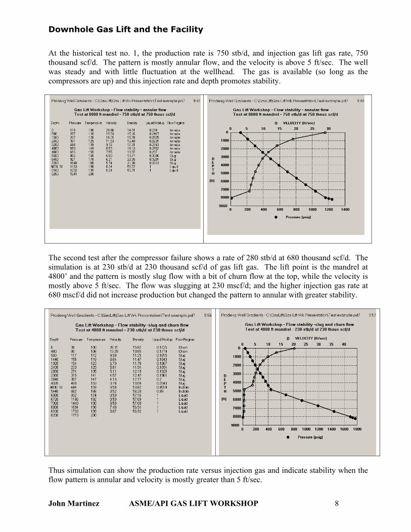
At the historical test no. 1, the production rate is 750 stb/d, and injection gas lift gas rate, 750 thousand scf/d. The pattern is mostly annular flow, and the velocity is above 5 ft/sec. The well was steady and with little fluctuation at the wellhead. The gas is available (so long as the compressors are up) and this injection rate and depth promotes stability.
The second test after the compressor failure shows a rate of 280 stb/d at 680 thousand scf/d. The simulation is at 230 stb/d at 230 thousand scf/d of gas lift gas. The lift point is the mandrel at 4800’ and the pattern is mostly slug flow with a bit of churn flow at the top, while the velocity is mostly above 5 ft/sec. The flow was slugging at 230 mscf/d; and the higher injection gas rate at 680 mscf/d did not increase production but changed the pattern to annular with greater stability.
Thus simulation can show the production rate versus injection gas and indicate stability when the flow pattern is annular and velocity is mostly greater than 5 ft/sec.
John Martinez ASME/API GAS LIFT WORKSHOP 8
Downhole Gas Lift and the Facility
Gas lift optimization is dependent on a combination of well performance and the facility availability. Keys are:
1. Compression on-line availability exceeding 99%. 2. Dehydration that is effective in reducing water content to less than 7 lb/million scf of gas
lift gas (approximately 3 lb/million scf in cold climate country). Freezing is one of the biggest causes of production loss and can often cause loss for a week while the system returns to normal.
3. Gas system design that incorporates compressors with low suction pressure and high discharge pressure, which enables a lift point near the packer. The benefit is greater production with fewer wells and less compressor horsepower per barrel of fluid lifted.
4. Field development plans should include simulation that provides reservoir pressure and water fraction prediction along with gas lift production deliverability. The operating factor should be incorporated into the requirement to meet the target production. The effect of separator pressure (compressor suction) on the well count required to meet target should be included in the analysis.
5. Measurement at the gas injection meters that is reliable, since the single-phase flow condition promotes good metering. This should be the dependable gas rate, not the total gas rate at the production test separator. Production testing is potentially less reliable when initial and final counts on the gas computer are used, and the surging gas rates are not indicated on a chart.
6. Flow stability requires both an annular flow pattern and downhole velocity of 5 ft/sec or up to 10 ft/sec. Ignore the velocity very near the surface since the low pressure causes velocity to increase substantially.
John Martinez ASME/API GAS LIFT WORKSHOP 9