Embed Size (px)
Citation preview

Downhole Flow Conditioning
to Improve Well Production
Economics
SPE Calgary Section
Reservoir Evaluation and
Production Optimization Luncheon
November 2016
© Production Plus Energy Services Inc., 2016

Agenda
1. Challenges producing horizontal wells
2. Root cause analysis
3. Development of the HEAL System
4. Case histories

© Production Plus Energy Serv ices Inc. 2016 | 3
Common challenges with artificial lift in horizontal wells
High Total Well Capital Expenditure
• Large artificial lift equipment due to production rate, depth and low efficiency
• Multiple lift systems required after natural flow period
• Complex directional profile to achieve production and geological objectives
High Operating Expenses
• Excessive workover frequency due to poor reliability and downhole equipment failures
• Excessive energy consumption due to pump depth and low pump efficiency
• Excessive gas interference and poor runtimes
Production and Reserves not Maximized
• Inadequate drawdown due to lift system limitations (gas lift, “pump limited”)
• Pump placement limiting ability to pump off well to very low bottomhole pressures
• Persistent high annular fluid levels or pump inlet pressure

© Production Plus Energy Serv ices Inc. 2016 | 4
OPEX risks
Complexity of depth, temperature, fluid composition
(gassy), rapidly declining rates has greatly increased
risks to the artificial lift system:
• Down Time Risk – pump gas interference, gas slugs (dry
operation, gas lock)
• Run Life Risk – solids, frac sand and fines, pump gas
interference
• Installation Risk – debris from pervious well interventions, solids, precipitates, high DLS, casing issues
• Downhole Flow Restriction Risk – drilling cost reduction initiatives have reduced casing ID’s, limiting production
drawdowns (the “600 psi producing BHP barrier”)
• Excessive Operating Cost Risk – frequent workovers and
operator attention
• Type Curve Risk – production rate and drawdowns
compromised with pumps landed above Hz section

© Production Plus Energy Serv ices Inc. 2016 | 5
Production engineer’s predicamentIntermediate artificial lift required before transitioning to rod pump
1. Production rate at bottom end of
natural flow period is greater than
top end of rod pumping capacity
• Intermediate artificial lift required
2. Want to natural flow as long as
possible (lowest OPEX)
3. Want to transition to rod pump as
quickly as possible to minimize
OPEX
4. Want to transition to rod pump as
quickly as possible to maximize
drawdown and well NPV

© Production Plus Energy Serv ices Inc. 2016 | 6
Reserves predicament identified
1. Artificial lift challenges are leading
to a reserve write down risk:
• actual production post high initial decline
(tail phase) is below reserve booking
• gas lifting limits drawdown, thus forced to
transition to rod pump
• gas lifting has higher OPEX, which
reduces reserves booking
• eventually must transition to rod pump for
more drawdown and lower OPEX.
“We need a solution that maximizes
drawdown reliably at lowest OPEX
possible, while minimizing artificial lift
system transitions”
Booked
reserves

© Production Plus Energy Serv ices Inc. 2016 | 7
Root cause of challenges: slug flow
Slug Flow Mechanisms:
1. Hydrodynamic Based – flow regime
(rates, GLR and pressure)
2. Terrain Based – well geometry
(undulations and toe-up trajectory)
3. Operational Based – interruptions,
stops/starts, pump on timer = bad
plan, pump over-stroking practices

© Production Plus Energy Serv ices Inc. 2016 | 8
Toe-up
• Large gas bubble forms at toe
• Gas bubble eventually becomes unstable
and releases in violent manner
• Large, extended gas flow periods
How a well is drilled impacts slug flow
Wellbore Undulations
• Liquid traps compound slugging
• Liquid traps do not create material pressure
drops, rather they exacerbate slugging

© Production Plus Energy Serv ices Inc. 2016 | 9
Gas expansion in an oil reservoirBelow 600 psi bottomhole pressure gas expansion is exponential
When producing BHP
is < 600 psi:
• Slug flow severity
increases dramatically
• Flow restrictions around
downhole components
amplifies slug flow
• Solids transport
increases significantly

© Production Plus Energy Serv ices Inc. 2016 | 10
Source: www.evcam.com
Slug flow transports solids along horizontal
Solids dunes in
horizontal caused
by slug flow
Solids are transported in
dunes along horizontal
due to wave mechanics
associated with slug flow
Transported solids
accumulate at the heel of
the horizontal well, where
pumps are commonly
positioned – high risk of
solids damage to pumps

© Production Plus Energy Serv ices Inc. 2016 | 11
Solids transport mechanism is slug flow
Reference: http://fluidsengineering.asmedigitalcoll
ection.asme.org/data/Journals/JFEGA
4/927034/fe_135_8_081304_f007.png

© Production Plus Energy Serv ices Inc. 2016 | 12
Slug flow mitigation techniques
1. Choke
Controlled pressure drop used to
eliminate slugs (minimum 500 psi often
required)
2. Slug Catchers
Common in pipeline industry; large
piping and process equipment required
3. Flow Conditioning
Application of specific multiphase flow
regimes to achieve the benefits of
choking but without the pressure lossReference:http://fluidsengineering.asmedigitalcollection.asme.org/data
/Journals/JFEGA4/927034/fe_135_8_081304_f007.png

© Production Plus Energy Serv ices Inc. 2016 | 13
Slug flow mitigation techniques
Surface Choke Simulation
Reference:H. Lee Norris III, SPE 158500, “The Use of a Transient Multiphase Simulator to Predict and Suppress Flow Instabilities in
a Horizontal Shale Oil Well”, SPE Annual Technical Conference and Exhibition, San Antonio Texas, USA, 8-10 October 2012
Downhole Flow Conditioning Simulation

© Production Plus Energy Serv ices Inc. 2016 | 14
Downhole flow conditioningDevelopment of the HEAL System
Reference: TriAxon Oil Corp. Harmattan East Viking Unit well 02/04-28-032-03W5
© Production Plus Energy Serv ices Inc. 2016 | 15
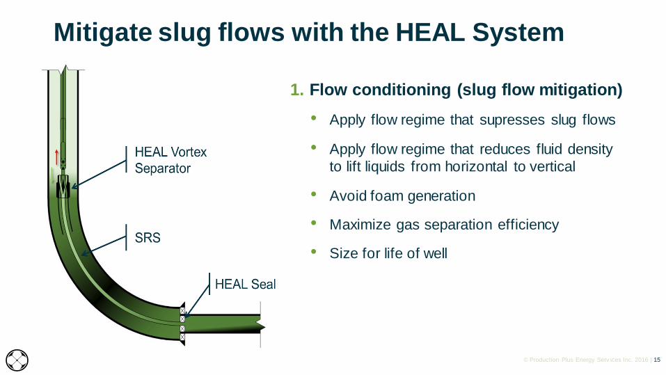
1. Flow conditioning (slug flow mitigation)
• Apply flow regime that supresses slug flows
• Apply flow regime that reduces fluid density
to lift liquids from horizontal to vertical
• Avoid foam generation
• Maximize gas separation efficiency
• Size for life of well
Mitigate slug flows with the HEAL System

© Production Plus Energy Serv ices Inc. 2016 | 16
Bo
tto
mh
ole
Pre
ss
ure
Tubing ID
Bubble Flow Slug Flow Annular Transition Mist
Source: Purdue University http://bit.ly/1OxEjm3
Sized regulating string flow conditioning

© Production Plus Energy Serv ices Inc. 2016 | 17
2. Place traditional artificial lift systems in
vertical
• Place moving parts (pump) in vertical for
reliability
• Smaller lift equipment or more capacity out of
existing equipment
• Lowers power consumption
• Maximize drawdown
3. Solids control
• Control solids transport mechanism in hz
• Solids separator with large sump for
collection of solids (to protect pump)
Mitigate slug flows with the HEAL System

© Production Plus Energy Serv ices Inc. 2016 | 18
Longevity: HEAL system sized for life of well

© Production Plus Energy Serv ices Inc. 2016 | 19
HEAL System results and challenges
0
100
200
300
400
500
600
700
0
20
40
60
80
100
Pro
du
cti
on
R
ate
(b
bl/d
)
Pro
du
cti
on
R
ate
(m
3/d
)
Oil (m3/d) Water (m3/d)
Anchor
Unset
Workover to
Reset Anchor
HEAL System demonstrates attractive
value proposition of highly capital
efficient production and reserves uplift

© Production Plus Energy Serv ices Inc. 2016 | 20
Case Study: Reliability
• Ran pumps deep to maximize drawdown
o multiple pump failures
• Ran pumps shallow for reliability
o poor drawdown, rod breaks from gas interference
• Pre-HEAL
o 9 pump changes in 2.25 years costing $600k
• Post-HEAL
o Zero changes in 2+ years

© Production Plus Energy Serv ices Inc. 2016 | 21
Case Study: ReliabilityImproved pump life and rod life in multiple installs in several basins:
• Wolfcamp, Permian Basin o longest running rod pump install for client and ongoing
• Niobrara, DJ Basin o for 2 years prior to the HEAL System, rod failures every 6 months
o 12 months post-install, no rod failures, ongoing
• Viking, Central Alberta, Canadao multiple solids related pump failures post-flowback
o since installs (20+) no failures
• Belly River, Central Alberta, Canada o multiple solids related pump failures
o since installs (10+) no failures
• Glauconite, Central Alberta, Canadao multiple solids related pump failures
o since installs no failures
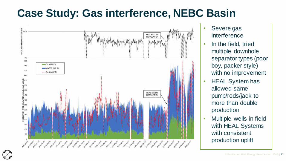
© Production Plus Energy Serv ices Inc. 2016 | 22
• Severe gas
interference
• In the field, tried
multiple downhole
separator types (poor
boy, packer style)
with no improvement
• HEAL System has
allowed same
pump/rods/jack to
more than double
production
• Multiple wells in field
with HEAL Systems
with consistent
production uplift
Case Study: Gas interference, NEBC Basin

© Production Plus Energy Serv ices Inc. 2016 | 23
• HEAL System solves
the root cause of
erratic pump fillage
• Regardless of the
performance of the
downhole separator,
like a properly design
packer style gas
separator, slug flow
leads to gas
interference
• Erratic pump fillage
compromises rod and
pump life
Case Study: Gas interference, Permian Basin

© Production Plus Energy Serv ices Inc. 2016 | 24
• HEAL System solves
the root cause of
erratic pump fillage
• Mitigating slug flows
improves both
downhole separation
and pump
performance
• Increase in pump
efficiency and a
shallower pump
placement reduces
energy consumption
up to 40%
Case Study: Gas interference, Niobrara DJ Basin

© Production Plus Energy Serv ices Inc. 2016 | 25
• Slug flow is a major impediment to achieving a
pumped off condition
• HEAL System positions pump in vertical section
~1200 feet above hz
o achieved lower producing
BHP than a pump
positioned at 80o inc
• Pump placed at or above KOP to improve reliability
and lower cost
o reduced size of pump /
rods / jack (cost), while
achieved reliable lower
producing BHP
Case Study: Low producing BHP, SE Sask

© Production Plus Energy Serv ices Inc. 2016 | 26
Case Study: Low producing BHP vs gas lift, Montney
• Gas lift has attractive
reliability, but high
OPEX and producing
BHP
• HEAL System + rod
pumping sustained
attractive reliability of
gas lift, but at
significantly lower
OPEX and producing
BHP

© Production Plus Energy Serv ices Inc. 2016 | 27
Case Study: Low BHP vs gas lift, Anadarko Basin
• Transition from ESP to gas lift resulted
in undesirable production performance and
higher OPEX
• HEAL System + rod pump maximized drawdown and the
well production potential
0
5
10
15
20
25
30
35
40
45
50
0
50
100
150
200
250
300
Flu
id P
rod
uct
ion
Ra
te (
m3/d
)
Flu
id P
rod
uc
tio
n R
ate
(b
bl/
d)
HE
AL
Syste
mIn
sta
lle
d
© Production Plus Energy Serv ices Inc. 2016 | 28
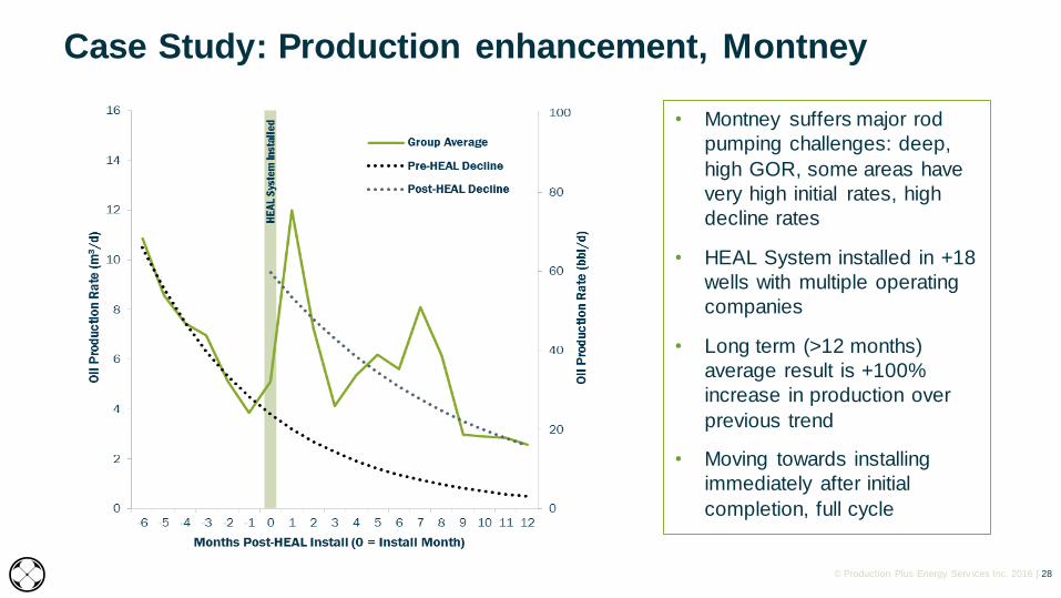
Case Study: Production enhancement, Montney
• Montney suffers major rod
pumping challenges: deep,
high GOR, some areas have
very high initial rates, high
decline rates
• HEAL System installed in +18
wells with multiple operating
companies
• Long term (>12 months)
average result is +100%
increase in production over
previous trend
• Moving towards installing
immediately after initial
completion, full cycle

© Production Plus Energy Serv ices Inc. 2016 | 29
Case Study: Production enhancement, gas lift
transition to rod pump, Permian Basin
• Wolfcamp formation is
challenged by depth,
high total fluid rates, high
watercuts and severe
high GOR gas
interference
• Installation in 7
Wolfcamp wells resulted
in a sustained +40%
increase in production

© Production Plus Energy Serv ices Inc. 2016 | 30
HEAL ESP System Pad Field Trial … Installed Sept 2016
Project Objective
• Drilled a 3 Well Horizontal Pad (~ 3000' to 7200' Hz sections)
• 2 wells conventional ESPs, 1 with HEAL ESP System
• Compare performance / cost reductions of HEAL System
• HEAL System Goal: Extend MTTF from 0.5 months to > 2 yrs
Production Challenges
• H2S up to 2%
• Solids production (frac sand) and scaling tendencies
• High liquid and gas rates / GOR’s (2000 to 3,000 scf/bbl)
Duvernay
Montney
Calgary

© Production Plus Energy Serv ices Inc. 2016 | 31
3 Well ESP Pad Comparison
Initial start-up
@ 52 Hz
SHUT DOWN PERIODS
TO REMOVE SAND

© Production Plus Energy Serv ices Inc. 2016 | 32
3 Well ESP Pad ComparisonInitial Observations
• All wells suggest consistent drawdown
• Pipeline restrictions have impacted continuous
operations @ 15-23 & 16-23
• Average Reductions at 14-23’s HEAL ESP
System:
1. 33% less HP/power
2. 20% less pump stages
3. 30% less tubing/cable
4. Smaller Motor – 456 vs 562 series
5. Considerably less solids in produced
fluids
WELL GAS
RATE
(MCF/D)
TOTAL
FLUID
(BBL/D)
14-23(HEAL)
900 1145
15-23 760 1182
16-23 500 1750

© Production Plus Energy Serv ices Inc. 2016 | 33
Summary
Flow conditioning for slug mitigation adds value
• Over 130 HEAL System installs across North America
Benefits of flow conditioning using Heal System
• Mitigate down time risks
• Mitigate run life risks (extend to 2-3 years target)
• Reduce OPEX and CAPEX
• Mitigate production type curve risks
• Controlled drawdown, drawdown reliability and managing high GORs
• Achieve very low producing BHP’s, reliably
© Production Plus Energy Serv ices Inc. 2016 | 34
HEAD OFFICE
403-536-8311
www.pdnplus.com
ADDRESS
2500, 639 - 5 Avenue SW
Calgary, AB | T2P 0M9
DISCLAIMERThis presentation is for use by the HEAL System™ user (User) only. User has sole responsibility for the use of theHEAL System™ and any field operations and installation activities in relation thereto and neither Production PlusEnergy Services Inc. nor any of its affiliates or representatives (collectively, Production Plus) shall have any liabilityto User under any circumstances in relation to any field operations of or installation activities conducted by User.
Production Plus does not makes any representations or warranties express, implied, statutory or otherwise as tothe HEAL System™ (including as to the merchantability or fitness for a particular purpose thereof) or as to theprocedures contained in this guide. No certainty of results is assured by Production Plus and Production Plusmakes no warranty concerning the accuracy or completeness of any data, the effectiveness of material used,recommendations given, or results of these procedures or technology.
User's use of the HEAL System™ is subject to the terms and conditions of its master sales agreement withProduction Plus Energy Services Inc.
DISTRIBUTIONThis presentation is the property of Production Plus Energy Services Inc. and its subsidiaries (the “Company”) and is strictly confidential. It contains information intended only for the person to whom it is transmitted. With receipt of this information, recipient acknowledges and agrees that: (i) this document is not intended to be distributed, and if distributed inadvertently, will be returned to the Company as soon as possible; (ii) the recipient will not copy, fax, reproduce, divulge, or distribute this confidential information, in whole or in part, without the express written consent of the Company; (iii) all of the information herein will be treated as confidential material with no less care than that afforded to its own confidential material. This presentation is for informational purposes only.
TRADEMARKHEAL System is a trademark of Production Plus Energy Services Inc.
JEFF SAPONJA, P.Eng.
1-403-472-1440
Questions?