Embed Size (px)
Citation preview
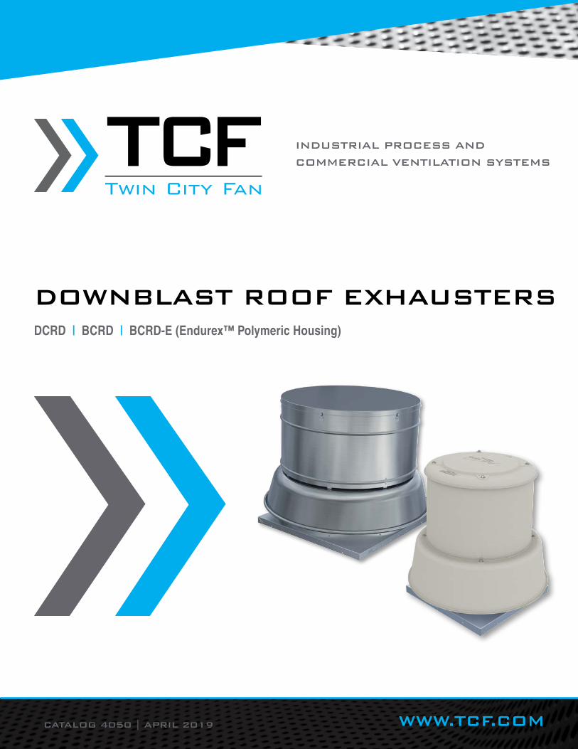
CATALOG 4050 | APRIL 2019 WWW.TCF.COM
INDUSTRIAL PROCESS AND
COMMERCIAL VENTILATION SYSTEMS
Twin City Fan
Twin City FanDOWNBLAST ROOF EXHAUSTERSDCRD | BCRD | BCRD-E (Endurex™ Polymeric Housing)
TWIN CITY FAN - CATALOG 40502
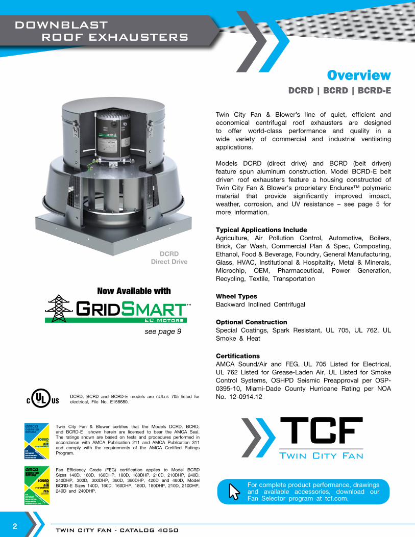
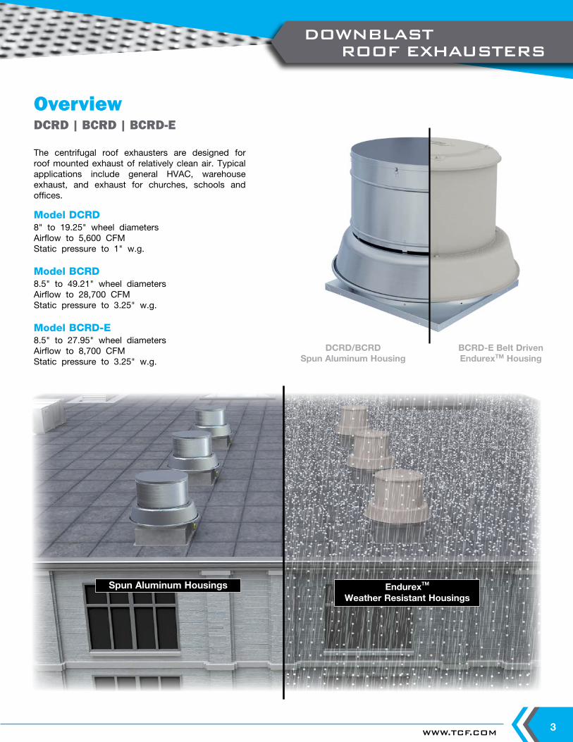
OverviewDCRD | BCRD | BCRD-E
DCRDDirect Drive
Twin City Fan & Blower certifies that the Models DCRD, BCRD, and BCRD-E shown herein are licensed to bear the AMCA Seal. The ratings shown are based on tests and procedures performed in accordance with AMCA Publication 211 and AMCA Publication 311 and comply with the requirements of the AMCA Certified Ratings Program.
Fan Efficiency Grade (FEG) certification applies to Model BCRD Sizes 140D, 160D, 160DHP, 180D, 180DHP, 210D, 210DHP, 240D, 240DHP, 300D, 300DHP, 360D, 360DHP, 420D and 480D, Model BCRD-E Sizes 140D, 160D, 160DHP, 180D, 180DHP, 210D, 210DHP, 240D and 240DHP.
DCRD, BCRD and BCRD-E models are cULus 705 listed for electrical, File No. E158680.
Twin City Fan & Blower’s line of quiet, efficient and economical centrifugal roof exhausters are designed to offer world-class performance and quality in a wide variety of commercial and industrial ventilating applications.
Models DCRD (direct drive) and BCRD (belt driven) feature spun aluminum construction. Model BCRD-E belt driven roof exhausters feature a housing constructed of Twin City Fan & Blower's proprietary Endurex™ polymeric material that provide significantly improved impact, weather, corrosion, and UV resistance – see page 5 for more information.
Typical Applications IncludeAgriculture, Air Pollution Control, Automotive, Boilers, Brick, Car Wash, Commercial Plan & Spec, Composting, Ethanol, Food & Beverage, Foundry, General Manufacturing, Glass, HVAC, Institutional & Hospitality, Metal & Minerals, Microchip, OEM, Pharmaceutical, Power Generation, Recycling, Textile, Transportation
Wheel TypesBackward Inclined Centrifugal
Optional ConstructionSpecial Coatings, Spark Resistant, UL 705, UL 762, UL Smoke & Heat
CertificationsAMCA Sound/Air and FEG, UL 705 Listed for Electrical, UL 762 Listed for Grease-Laden Air, UL Listed for Smoke Control Systems, OSHPD Seismic Preapproval per OSP-0395-10, Miami-Dade County Hurricane Rating per NOA No. 12-0914.12
EC MotorsGridSmart
EC MotorsGridSmartTM
TM
Now Available with
see page 9
Twin City Fan
Twin City Fan
For complete product performance, drawings and available accessories, download our Fan Selector program at tcf.com.
DOWNBLAST ROOF EXHAUSTERS
WWW.TCF.COM 3
Model DCRD8" to 19.25" wheel diametersAirflow to 5,600 CFMStatic pressure to 1" w.g.
Model BCRD8.5" to 49.21" wheel diametersAirflow to 28,700 CFMStatic pressure to 3.25" w.g.
Model BCRD-E8.5" to 27.95" wheel diametersAirflow to 8,700 CFMStatic pressure to 3.25" w.g.
DCRD/BCRDSpun Aluminum Housing
BCRD-E Belt DrivenEndurexTM Housing
The centrifugal roof exhausters are designed for roof mounted exhaust of relatively clean air. Typical applications include general HVAC, warehouse exhaust, and exhaust for churches, schools and offices.
OverviewDCRD | BCRD | BCRD-E
Spun Aluminum Housings EndurexTM
Weather Resistant Housings
DOWNBLAST ROOF EXHAUSTERS
TWIN CITY FAN - CATALOG 40504
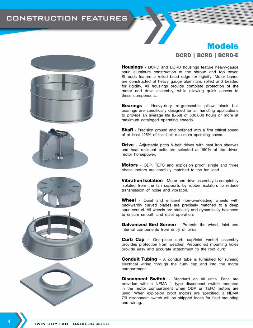
ModelsDCRD | BCRD | BCRD-E
Housings - BCRD and DCRD housings feature heavy-gauge spun aluminum construction of the shroud and top cover. Shrouds feature a rolled bead edge for rigidity. Motor bands are constructed of heavy gauge aluminum, rolled and beaded for rigidity. All housings provide complete protection of the motor and drive assembly, while allowing quick access to these components.
Bearings - Heavy-duty re-greaseable pillow block ball bearings are specifically designed for air handling applications to provide an average life (L-50) of 500,000 hours or more at maximum cataloged operating speeds.
Shaft - Precision ground and polished with a first critical speed of at least 125% of the fan’s maximum operating speed.
Drive - Adjustable pitch V-belt drives with cast iron sheaves and heat resistant belts are selected at 150% of the driven motor horsepower.
Motors - ODP, TEFC and explosion proof, single and three phase motors are carefully matched to the fan load.
Vibration Isolation - Motor and drive assembly is completely isolated from the fan supports by rubber isolators to reduce transmission of noise and vibration.
Wheel - Quiet and efficient non-overloading wheels with backwardly curved blades are precisely matched to a deep spun venturi. All wheels are statically and dynamically balanced to ensure smooth and quiet operation.
Galvanized Bird Screen - Protects the wheel, inlet and internal components from entry of birds.
Curb Cap - One-piece curb cap/inlet venturi assembly provides protection from weather. Prepunched mounting holes provide easy and accurate attachment to the roof curb.
Conduit Tubing - A conduit tube is furnished for running electrical wiring through the curb cap and into the motor compartment.
Disconnect Switch - Standard on all units. Fans are provided with a NEMA 1 type disconnect switch mounted in the motor compartment when ODP or TEFC motors are used. When explosion proof motors are specified, a NEMA 7/9 disconnect switch will be shipped loose for field mounting and wiring.
CONSTRUCTION FEATURES
WWW.TCF.COM 5
The Endurex™ housing was tested by UL in accordance with UL 94, 746A, and 746C and is approved as UL 705 listed. The Endurex™ material underwent rigid testing per these standards, surpassing the requirements of the following:
Ultraviolet Light Exposure Testing – Samples were exposed to ultra violet light for an equivalent of 500,000 hours (90+ years) to provide the assurance that the material will last a lifetime.
Flammability Testing – Flame tests performed per UL 94, the most widely accepted flammability performance standards for plastic materials, gauged the material’s ability to propagate or extinguish a flame once ignited.
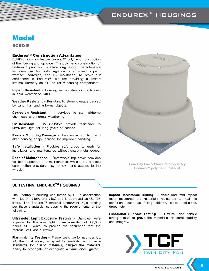
Endurex™ Construction AdvantagesBCRD-E housings feature Endurex™ polymeric construction of the housing and top cover. The polymeric construction of Endurex™ provides the same long lasting characteristics as aluminum but with significantly improved impact, weather, corrosion, and UV resistance. To prove our confidence in Endurex™ we are providing a limited lifetime warranty on all Endurex™ housing components.
Impact Resistant - Housing will not dent or crack even in cold weather to -40oF.
Weather Resistant - Resistant to storm damage caused by wind, hail and airborne objects.
Corrosion Resistant - Impervious to salt, airborne chemicals and normal weathering.
UV Resistant - UV inhibitors provide resistance to ultraviolet light for long years of service.
Resists Shipping Damage - Impossible to dent and alter housing shape caused by improper handling.
Safe Installation - Provides safe areas to grab for installation and maintenance without sharp metal edges.
Ease of Maintenance - Removable top cover provides for belt inspection and maintenance, while the one-piece construction provides easy removal and access to the wheel.
ModelBCRD-E
UL TESTING, ENDUREXTM HOUSINGS
Impact Resistance Testing – Tensile and izod impact tests measured the material’s resistance to real life conditions such as falling objects, blows, collisions, drops, etc.
Functional Support Testing – Flexural and tensile strength tests to prove the material’s structural stability and integrity.
Twin City Fan & Blower's proprietary Endurex™ polymeric material
ENDUREX™ HOUSINGS
Twin City Fan
Twin City Fan
TWIN CITY FAN - CATALOG 40506
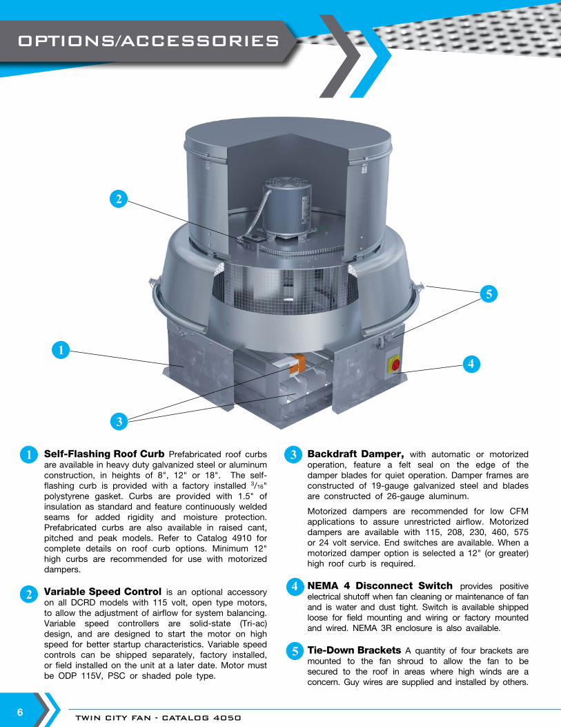
Self-Flashing Roof Curb Prefabricated roof curbs are available in heavy duty galvanized steel or aluminum construction, in heights of 8", 12" or 18". The self-flashing curb is provided with a factory installed 3/16" polystyrene gasket. Curbs are provided with 1.5" of insulation as standard and feature continuously welded seams for added rigidity and moisture protection. Prefabricated curbs are also available in raised cant, pitched and peak models. Refer to Catalog 4910 for complete details on roof curb options. Minimum 12" high curbs are recommended for use with motorized dampers.
Variable Speed Control is an optional accessory on all DCRD models with 115 volt, open type motors, to allow the adjustment of airflow for system balancing. Variable speed controllers are solid-state (Tri-ac) design, and are designed to start the motor on high speed for better startup characteristics. Variable speed controls can be shipped separately, factory installed, or field installed on the unit at a later date. Motor must be ODP 115V, PSC or shaded pole type.
2
1 3 Backdraft Damper, with automatic or motorized operation, feature a felt seal on the edge of the damper blades for quiet operation. Damper frames are constructed of 19-gauge galvanized steel and blades are constructed of 26-gauge aluminum.
Motorized dampers are recommended for low CFM applications to assure unrestricted airflow. Motorized dampers are available with 115, 208, 230, 460, 575 or 24 volt service. End switches are available. When a motorized damper option is selected a 12" (or greater) high roof curb is required.
NEMA 4 Disconnect Switch provides positive electrical shutoff when fan cleaning or maintenance of fan and is water and dust tight. Switch is available shipped loose for field mounting and wiring or factory mounted and wired. NEMA 3R enclosure is also available.
Tie-Down Brackets A quantity of four brackets are mounted to the fan shroud to allow the fan to be secured to the roof in areas where high winds are a concern. Guy wires are supplied and installed by others.
4
5
1
2
4
5
3
OPTIONS/ACCESSORIES
WWW.TCF.COM 7
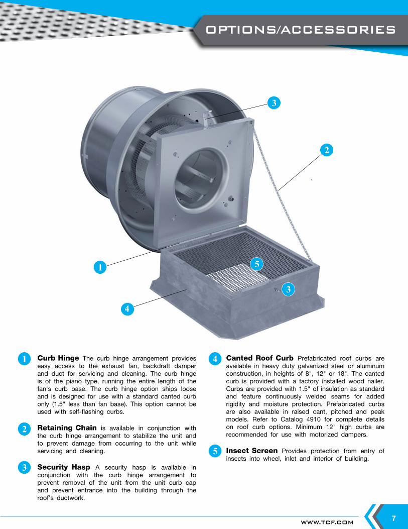
Curb Hinge The curb hinge arrangement provides easy access to the exhaust fan, backdraft damper and duct for servicing and cleaning. The curb hinge is of the piano type, running the entire length of the fan's curb base. The curb hinge option ships loose and is designed for use with a standard canted curb only (1.5" less than fan base). This option cannot be used with self-flashing curbs.
Retaining Chain is available in conjunction with the curb hinge arrangement to stabilize the unit and to prevent damage from occurring to the unit while servicing and cleaning.
Security Hasp A security hasp is available in conjunction with the curb hinge arrangement to prevent removal of the unit from the unit curb cap and prevent entrance into the building through the roof’s ductwork.
2
1 Canted Roof Curb Prefabricated roof curbs are available in heavy duty galvanized steel or aluminum construction, in heights of 8", 12" or 18". The canted curb is provided with a factory installed wood nailer. Curbs are provided with 1.5" of insulation as standard and feature continuously welded seams for added rigidity and moisture protection. Prefabricated curbs are also available in raised cant, pitched and peak models. Refer to Catalog 4910 for complete details on roof curb options. Minimum 12" high curbs are recommended for use with motorized dampers.
Insect Screen Provides protection from entry of insects into wheel, inlet and interior of building.
3
5
4
1 5
2
3
4
3
OPTIONS/ACCESSORIES
TWIN CITY FAN - CATALOG 40508
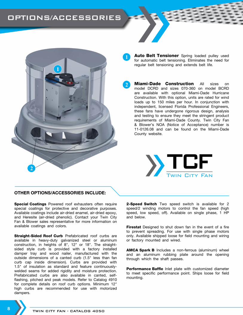
Miami-Dade Construction All sizes on model DCRD and sizes 070-360 on model BCRD are available with optional Miami-Dade Hurricane Construction. With this option, units are rated for wind loads up to 150 miles per hour. In conjunction with independent, licensed Florida Professional Engineers, these fans have undergone rigorous design, analysis and testing to ensure they meet the stringent product requirements of Miami-Dade County. Twin City Fan & Blower’s NOA (Notice of Acceptance) number is 11-0126.08 and can be found on the Miami-Dade County website.
1
2
Auto Belt Tensioner Spring loaded pulley used for automatic belt tensioning. Eliminates the need for regular belt tensioning and extends belt life.
OTHER OPTIONS/ACCESSORIES INCLUDE:
Special Coatings Powered roof exhausters often require special coatings for protective and decorative purposes. Available coatings include air-dried enamel, air-dried epoxy, and Heresite (air-dried phenolic). Contact your Twin City Fan & Blower sales representative for more information on available coatings and colors.
Straight-Sided Roof Curb Prefabricated roof curbs are available in heavy-duty galvanized steel or aluminum construction, in heights of 8", 12" or 18". The straight-sided style curb is provided with a factory installed damper tray and wood nailer, manufactured with the outside dimensions of a canted curb (1.5" less than fan curb cap inside dimension). Curbs are provided with 1.5" of insulation as standard and feature continuously-welded seams for added rigidity and moisture protection. Prefabricated curbs are also available in canted, self-flashing, pitched and peak models. Refer to Catalog 4910 for complete details on roof curb options. Minimum 12" high curbs are recommended for use with motorized dampers.
2-Speed Switch Two speed switch is available for 2 speed/2 winding motors to control the fan speed (high speed, low speed, off). Available on single phase, 1 HP and below.
Firestat Designed to shut down fan in the event of a fire to prevent spreading. For use with single phase motors only. Available shipped loose for field mounting and wiring or factory mounted and wired.
AMCA Spark B Includes a non-ferrous (aluminum) wheel and an aluminum rubbing plate around the opening through which the shaft passes.
Performance Baffle Inlet plate with customized diameter to meet specific performance point. Ships loose for field mounting.
2
1
OPTIONS/ACCESSORIES
Twin City Fan
Twin City Fan
WWW.TCF.COM 9
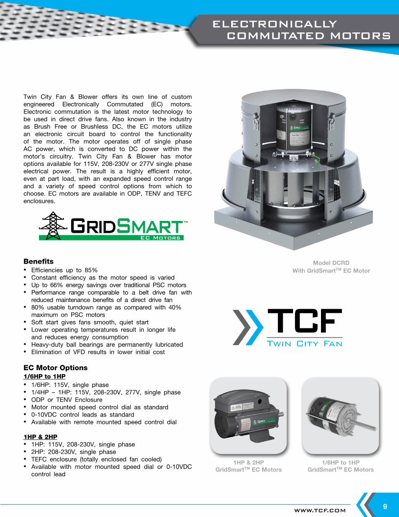
Twin City Fan & Blower offers its own line of custom engineered Electronically Commutated (EC) motors. Electronic commutation is the latest motor technology to be used in direct drive fans. Also known in the industry as Brush Free or Brushless DC, the EC motors utilize an electronic circuit board to control the functionality of the motor. The motor operates off of single phase AC power, which is converted to DC power within the motor’s circuitry. Twin City Fan & Blower has motor options available for 115V, 208-230V or 277V single phase electrical power. The result is a highly efficient motor, even at part load, with an expanded speed control range and a variety of speed control options from which to choose. EC motors are available in ODP, TENV and TEFC enclosures.
Benefits• Efficiencies up to 85%• Constant efficiency as the motor speed is varied• Up to 66% energy savings over traditional PSC motors• Performance range comparable to a belt drive fan with
reduced maintenance benefits of a direct drive fan• 80% usable turndown range as compared with 40%
maximum on PSC motors • Soft start gives fans smooth, quiet start• Lower operating temperatures result in longer life
and reduces energy consumption• Heavy-duty ball bearings are permanently lubricated• Elimination of VFD results in lower initial cost
EC Motor Options1/6HP to 1HP• 1/6HP: 115V, single phase• 1/4HP – 1HP: 115V, 208-230V, 277V, single phase• ODP or TENV Enclosure• Motor mounted speed control dial as standard• 0-10VDC control leads as standard• Available with remote mounted speed control dial
1HP & 2HP• 1HP: 115V, 208-230V, single phase• 2HP: 208-230V, single phase• TEFC enclosure (totally enclosed fan cooled)• Available with motor mounted speed dial or 0-10VDC
control lead
EC MotorsGridSmart
EC MotorsGridSmartTM
TM
Model DCRDWith GridSmartTM EC Motor
1/6HP to 1HPGridSmartTM EC Motors
1HP & 2HPGridSmartTM EC Motors
ELECTRONICALLY COMMUTATED MOTORS
Twin City Fan
Twin City Fan
TWIN CITY FAN - CATALOG 405010
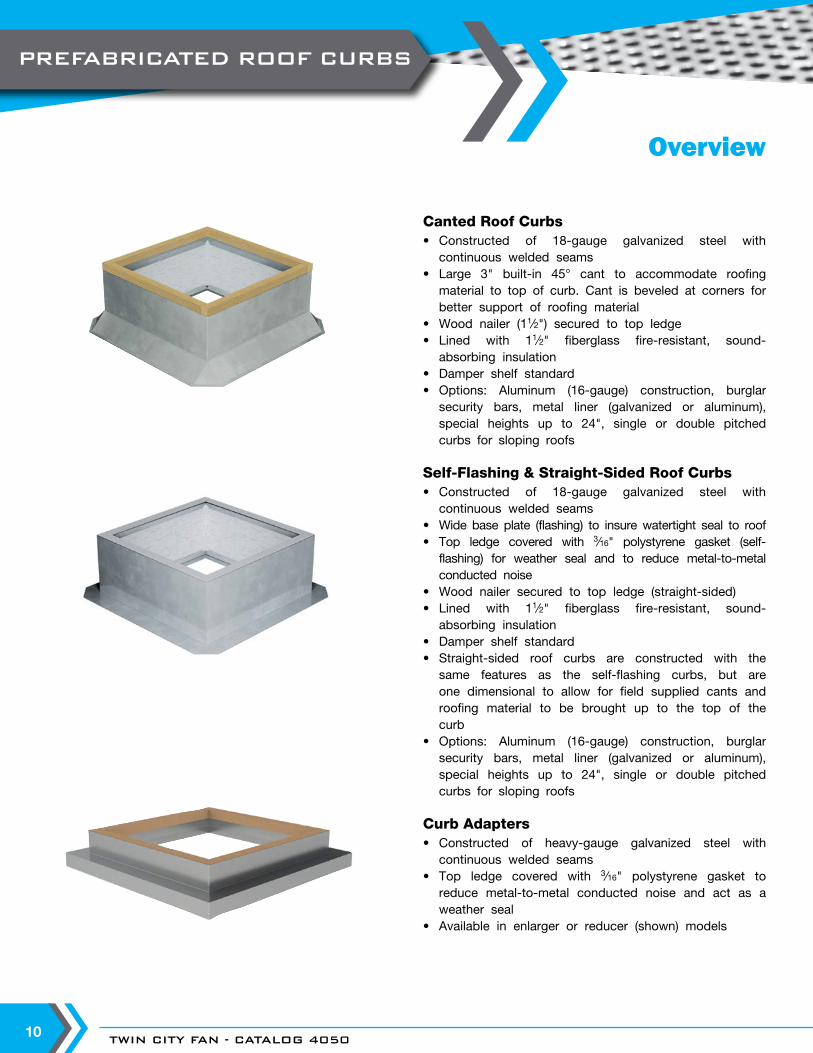
Canted Roof Curbs• Constructed of 18-gauge galvanized steel with
continuous welded seams• Large 3" built-in 45° cant to accommodate roofing
material to top of curb. Cant is beveled at corners for better support of roofing material
• Wood nailer (11∕2") secured to top ledge• Lined with 11∕2" fiberglass fire-resistant, sound-
absorbing insulation• Damper shelf standard• Options: Aluminum (16-gauge) construction, burglar
security bars, metal liner (galvanized or aluminum), special heights up to 24", single or double pitched curbs for sloping roofs
Self-Flashing & Straight-Sided Roof Curbs• Constructed of 18-gauge galvanized steel with
continuous welded seams• Wide base plate (flashing) to insure watertight seal to roof• Top ledge covered with 3∕16" polystyrene gasket (self-
flashing) for weather seal and to reduce metal-to-metal conducted noise
• Wood nailer secured to top ledge (straight-sided)• Lined with 11∕2" fiberglass fire-resistant, sound-
absorbing insulation• Damper shelf standard• Straight-sided roof curbs are constructed with the
same features as the self-flashing curbs, but are one dimensional to allow for field supplied cants and roofing material to be brought up to the top of the curb
• Options: Aluminum (16-gauge) construction, burglar security bars, metal liner (galvanized or aluminum), special heights up to 24", single or double pitched curbs for sloping roofs
Curb Adapters• Constructed of heavy-gauge galvanized steel with
continuous welded seams• Top ledge covered with 3∕16" polystyrene gasket to
reduce metal-to-metal conducted noise and act as a weather seal
• Available in enlarger or reducer (shown) models
Overview
PREFABRICATED ROOF CURBS
WWW.TCF.COM 11
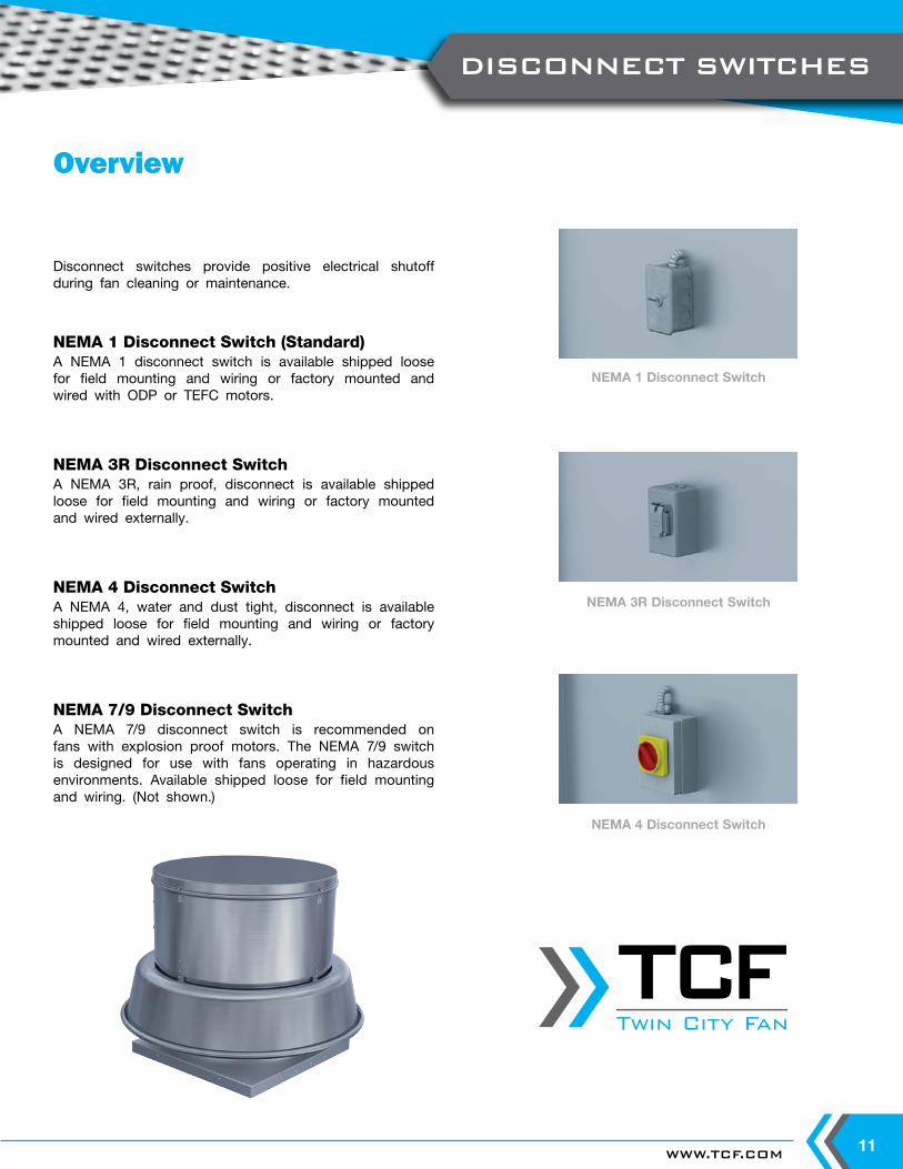
Overview
NEMA 1 Disconnect Switch
NEMA 3R Disconnect Switch
NEMA 4 Disconnect Switch
Disconnect switches provide positive electrical shutoff during fan cleaning or maintenance.
NEMA 1 Disconnect Switch (Standard)A NEMA 1 disconnect switch is available shipped loose for field mounting and wiring or factory mounted and wired with ODP or TEFC motors.
NEMA 3R Disconnect SwitchA NEMA 3R, rain proof, disconnect is available shipped loose for field mounting and wiring or factory mounted and wired externally.
NEMA 4 Disconnect SwitchA NEMA 4, water and dust tight, disconnect is available shipped loose for field mounting and wiring or factory mounted and wired externally.
NEMA 7/9 Disconnect SwitchA NEMA 7/9 disconnect switch is recommended on fans with explosion proof motors. The NEMA 7/9 switch is designed for use with fans operating in hazardous environments. Available shipped loose for field mounting and wiring. (Not shown.)
DISCONNECT SWITCHES
Twin City Fan
Twin City Fan
TWIN CITY FAN - CATALOG 405012
NOTES:
1. The AMCA Seal for sound ratings does not apply to units with speed control.2. Performance certified is for installation Type A: Free inlet, Free outlet.3. Performance ratings do not include the effects of appurtenances (accessories).4. Sound ratings shown are loudness values in fan sones at 5 ft. (1.5 m) in a hemispherical free field calculated per AMCA Standard 301-90.
Type A: Free inlet fan hemispherical sone levels. 5. Highlighted speeds indicate nominal speeds without speed control on PSC motors. All other speeds are intermediate speeds set with the
solid-state speed controller.6. 1/8 HP motor is 3-speed (1650 RPM/1500 RPM/1350 RPM).7. Speed control on PSC motors is available for ODP 115/60/1 only. PSC motors are wired at either the 1650 or the 1500 RPM taps.
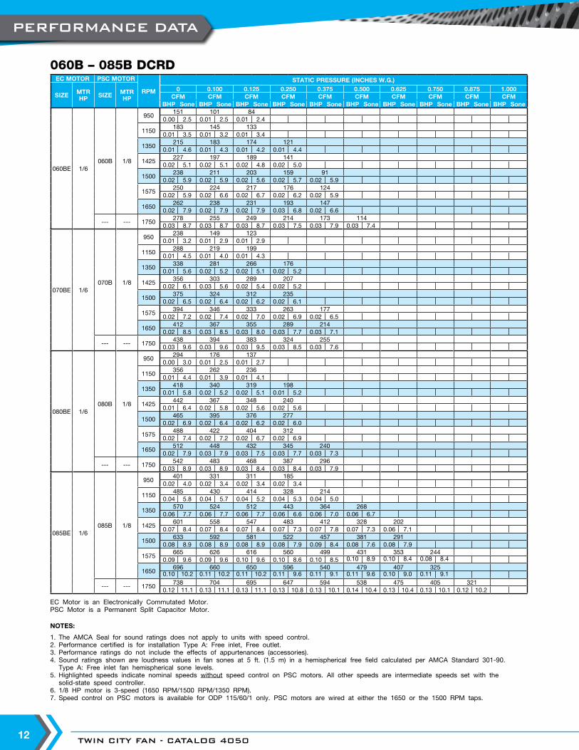
EC MOTOR PSC MOTOR
RPM
STATIC PRESSURE (INCHES W.G.)
SIZE MTRHP SIZE MTR
HP
0 0.100 0.125 0.250 0.375 0.500 0.625 0.750 0.875 1.000CFM CFM CFM CFM CFM CFM CFM CFM CFM CFM
BHP Sone BHP Sone BHP Sone BHP Sone BHP Sone BHP Sone BHP Sone BHP Sone BHP Sone BHP Sone
060BE 1/6060B 1/8
950151 101 84
0.00 2.5 0.01 2.5 0.01 2.4
1150183 145 133
0.01 3.5 0.01 3.2 0.01 3.4
1350215 183 174 121
0.01 4.6 0.01 4.3 0.01 4.2 0.01 4.4
1425227 197 189 141
0.02 5.1 0.02 5.1 0.02 4.8 0.02 5.0
1500238 211 203 159 91
0.02 5.9 0.02 5.9 0.02 5.6 0.02 5.7 0.02 5.9
1575250 224 217 176 124
0.02 5.9 0.02 6.6 0.02 6.7 0.02 6.2 0.02 5.9
1650262 238 231 193 147
0.02 7.9 0.02 7.9 0.02 7.9 0.03 6.8 0.02 6.6
--- --- 1750278 255 249 214 173 114
0.03 8.7 0.03 8.7 0.03 8.7 0.03 7.5 0.03 7.9 0.03 7.4
070BE 1/6070B 1/8
950238 149 123
0.01 3.2 0.01 2.9 0.01 2.9
1150288 219 199
0.01 4.5 0.01 4.0 0.01 4.3
1350338 281 266 176
0.01 5.6 0.02 5.2 0.02 5.1 0.02 5.2
1425356 303 289 207
0.02 6.1 0.03 5.6 0.02 5.4 0.02 5.2
1500375 324 312 235
0.02 6.5 0.02 6.4 0.02 6.2 0.02 6.1
1575394 346 333 263 177
0.02 7.2 0.02 7.4 0.02 7.0 0.02 6.9 0.02 6.5
1650412 367 355 289 214
0.02 8.5 0.03 8.5 0.03 8.0 0.03 7.7 0.03 7.1
--- --- 1750438 394 383 324 255
0.03 9.6 0.03 9.6 0.03 9.5 0.03 8.5 0.03 7.6
080BE 1/6080B 1/8
950294 176 137
0.00 3.0 0.01 2.5 0.01 2.7
1150356 262 236
0.01 4.4 0.01 3.9 0.01 4.1
1350418 340 319 198
0.01 5.8 0.02 5.2 0.02 5.1 0.01 5.2
1425442 367 348 240
0.01 6.4 0.02 5.8 0.02 5.6 0.02 5.6
1500465 395 376 277
0.02 6.9 0.02 6.4 0.02 6.2 0.02 6.0
1575488 422 404 312
0.02 7.4 0.02 7.2 0.02 6.7 0.02 6.9
1650512 448 432 345 240
0.02 7.9 0.03 7.9 0.03 7.5 0.03 7.7 0.03 7.3
--- --- 1750542 483 468 387 296
0.03 8.9 0.03 8.9 0.03 8.4 0.03 8.4 0.03 7.9
085BE 1/6085B 1/8
950401 331 311 185
0.02 4.0 0.02 3.4 0.02 3.4 0.02 3.4
1150485 430 414 328 214
0.04 5.8 0.04 5.7 0.04 5.2 0.04 5.3 0.04 5.0
1350570 524 512 443 364 268
0.06 7.7 0.06 7.7 0.06 7.7 0.06 6.6 0.06 7.0 0.06 6.7
1425601 558 547 483 412 328 202
0.07 8.4 0.07 8.4 0.07 8.4 0.07 7.3 0.07 7.8 0.07 7.3 0.06 7.1
1500633 592 581 522 457 381 291
0.08 8.9 0.08 8.9 0.08 8.9 0.08 7.9 0.09 8.4 0.08 7.6 0.08 7.9
1575665 626 616 560 499 431 353 244
0.09 9.6 0.09 9.6 0.10 9.6 0.10 8.6 0.10 8.5 0.10 8.9 0.10 8.4 0.08 8.4
1650696 660 650 596 540 479 407 325
0.10 10.2 0.11 10.2 0.11 10.2 0.11 9.6 0.11 9.1 0.11 9.6 0.10 9.0 0.11 9.1
--- --- 1750738 704 695 647 594 538 475 405 321
0.12 11.1 0.13 11.1 0.13 11.1 0.13 10.8 0.13 10.1 0.14 10.4 0.13 10.4 0.13 10.1 0.12 10.2
EC Motor is an Electronically Commutated Motor.PSC Motor is a Permanent Split Capacitor Motor.
060B – 085B DCRD
PERFORMANCE DATA
WWW.TCF.COM 13
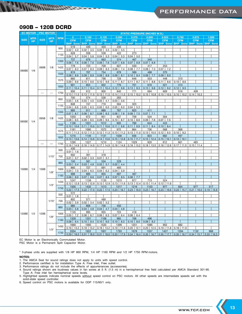
* 3-phase units are supplied with 1/8 HP 860 RPM, 1/4 HP 1160 RPM and 1/2 HP 1750 RPM motors.
NOTES:1. The AMCA Seal for sound ratings does not apply to units with speed control.2. Performance certified is for installation Type A: Free inlet, Free outlet.3. Performance ratings do not include the effects of appurtenances (accessories).4. Sound ratings shown are loudness values in fan sones at 5 ft. (1.5 m) in a hemispherical free field calculated per AMCA Standard 301-90.
Type A: Free inlet fan hemispherical sone levels. 5. Highlighted speeds indicate nominal speeds without speed control on PSC motors. All other speeds are intermediate speeds set with the
solid-state speed controller.6. Speed control on PSC motors is available for ODP 115/60/1 only.
EC Motor is an Electronically Commutated Motor.PSC Motor is a Permanent Split Capacitor Motor.
EC MOTOR PSC MOTOR
RPM
STATIC PRESSURE (INCHES W.G.)
SIZE MTRHP SIZE MTR
HP
0 0.100 0.125 0.250 0.375 0.500 0.625 0.750 0.875 1.000CFM CFM CFM CFM CFM CFM CFM CFM CFM CFM
BHP Sone BHP Sone BHP Sone BHP Sone BHP Sone BHP Sone BHP Sone BHP Sone BHP Sone BHP Sone
090BE 1/6090B 1/8
950519 430 403 235
0.02 4.0 0.02 3.5 0.02 3.5 0.02 3.5
1150628 558 538 422 273
0.04 5.7 0.04 5.6 0.04 5.3 0.04 5.3 0.04 5.0
1350737 679 663 574 467 340
0.06 7.6 0.06 7.6 0.06 7.6 0.07 6.8 0.07 6.8 0.07 6.8
1425778 723 709 627 530 417 253
0.07 8.3 0.07 8.3 0.08 8.3 0.08 7.4 0.08 7.7 0.08 7.3 0.07 7.2
1500819 767 754 678 589 488 370
0.08 8.9 0.09 8.9 0.09 8.9 0.09 8.1 0.10 8.4 0.09 7.7 0.09 8.0
1575860 811 798 728 646 553 448 310
0.09 9.6 0.10 9.6 0.10 9.6 0.11 8.7 0.11 8.7 0.11 8.8 0.11 8.6 0.10 8.6
1650901 854 842 776 701 616 521 413
0.11 10.4 0.11 10.4 0.11 10.4 0.12 9.8 0.13 9.3 0.13 9.8 0.12 9.2 0.12 9.5
--- --- 1750956 912 900 840 771 694 609 516 409
0.13 11.5 0.13 11.5 0.13 11.5 0.14 11.0 0.15 10.2 0.15 10.8 0.15 10.5 0.15 10.2 0.14 10.3
095BE 1/4095B 1/8
950700 574 538 283
0.03 4.6 0.03 4.0 0.03 4.1 0.03 3.6
1150848 747 719 564 323
0.04 6.6 0.05 6.3 0.05 6.0 0.05 6.0 0.04 5.3
1350995 911 889 767 623 411
0.07 8.7 0.08 8.7 0.08 8.3 0.08 7.8 0.08 7.5 0.07 7.1
14251050 972 951 837 709 534 304
0.08 9.5 0.09 9.5 0.09 9.5 0.10 8.7 0.10 8.9 0.09 7.8 0.07 7.5
15001106 1031 1012 905 789 644 443
0.10 10.6 0.11 10.6 0.11 10.6 0.11 9.8 0.11 9.9 0.11 8.4 0.10 8.4
15751161 1090 1072 972 864 736 568 368
0.11 11.3 0.12 11.3 0.12 11.3 0.13 11.2 0.13 11.0 0.13 10.5 0.12 9.5 0.10 9.2
16501216 1149 1131 1038 936 823 682 497
0.13 13.6 0.14 13.6 0.14 13.6 0.15 12.8 0.15 11.7 0.15 12.4 0.15 10.1 0.13 10.1
--- --- 17501290 1227 1210 1124 1029 929 812 661 483
0.16 14.9 0.16 14.9 0.17 14.9 0.18 14.8 0.18 13.2 0.18 13.5 0.18 12.8 0.17 11.5 0.15 11.4
100BE 1/4 100B
1/15*
500430
0.01 1.6
700602 391 318
0.01 3.7 0.02 3.3 0.01 3.1
860740 581 534 229
0.03 5.4 0.03 4.8 0.03 5.1 0.02 4.4
1/8*1000
860 727 691 4650.04 7.0 0.04 6.5 0.04 6.2 0.04 5.9
1160998 885 855 687 467
0.06 9.0 0.07 8.6 0.07 8.5 0.07 8.5 0.06 7.7
1/3*1450
1247 1158 1135 1015 877 713 5240.12 12.9 0.13 12.9 0.13 12.9 0.13 11.6 0.13 12.4 0.13 11.4 0.12 11.6
17501505 1432 1413 1317 1216 1103 977 834 677 517
0.22 17.5 0.22 17.5 0.22 17.5 0.23 16.7 0.23 16.0 0.23 16.7 0.23 16.6 0.22 15.7 0.21 16.0 0.19 15.9
120BE 1/2 120B
1/15*
500572
0.01 1.8
700802 571 489
0.02 3.9 0.02 3.4 0.02 3.2
860985 806 756 450
0.03 5.8 0.04 4.8 0.04 4.7 0.04 4.8
1/8*1000
1145 995 955 723 4180.05 7.2 0.06 6.7 0.06 6.3 0.07 6.4 0.06 6.4
11601328 1201 1168 985 768 496
0.08 9.4 0.10 9.4 0.10 9.0 0.10 8.3 0.10 8.0 0.09 8.2
1/3*1450
1660 1560 1535 1399 1251 1085 902 6820.16 13.2 0.18 13.2 0.18 13.2 0.19 11.9 0.20 12.1 0.20 12.5 0.19 11.8 0.18 11.9
17502004 1922 1901 1793 1678 1557 1427 1284 1132 968
0.29 18.0 0.31 18.0 0.31 18.0 0.33 17.9 0.34 16.4 0.35 16.7 0.35 17.7 0.35 16.7 0.34 15.7 0.33 16.3
090B – 120B DCRD
PERFORMANCE DATA
TWIN CITY FAN - CATALOG 405014
NOTES:1. The AMCA Seal for sound ratings does not apply to units with speed control.2. Performance certified is for installation Type A: Free inlet, Free outlet.3. Performance ratings do not include the effects of appurtenances (accessories).4. Sound ratings shown are loudness values in fan sones at 5 ft. (1.5 m) in a hemispherical free field calculated per AMCA Standard 301-90. Type
A: Free inlet fan hemispherical sone levels. 5. Highlighted speeds indicate nominal speeds without speed control on PSC motors. All other speeds are intermediate speeds set with the solid-
state speed controller.6. Speed control on PSC motors is available for ODP 115/60/1 only.
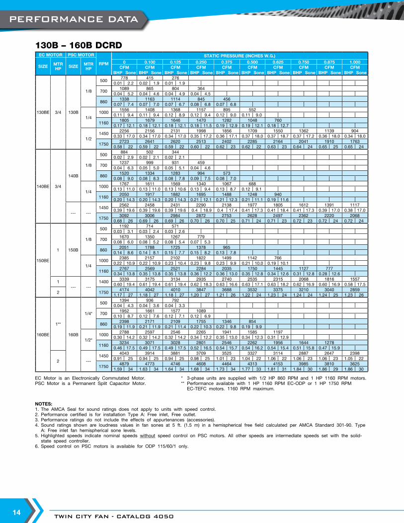
EC MOTOR PSC MOTOR
RPM
STATIC PRESSURE (INCHES W.G.)
SIZE MTRHP SIZE MTR
HP
0 0.100 0.125 0.250 0.375 0.500 0.625 0.750 0.875 1.000CFM CFM CFM CFM CFM CFM CFM CFM CFM CFM
BHP Sone BHP Sone BHP Sone BHP Sone BHP Sone BHP Sone BHP Sone BHP Sone BHP Sone BHP Sone
130BE 3/4 130B
1/8
500778 415 276
0.01 2.2 0.02 1.9 0.01 1.9
7001089 865 804 364
0.04 5.2 0.04 4.6 0.04 4.9 0.04 4.5
8601338 1163 1114 845 456
0.07 7.4 0.07 7.0 0.07 6.7 0.08 6.8 0.07 6.8
1/41000
1556 1408 1368 1157 895 5520.11 9.4 0.11 9.4 0.12 8.9 0.12 9.4 0.12 9.0 0.11 9.0
11601805 1679 1646 1470 1282 1048 760
0.17 12.1 0.18 12.1 0.18 12.1 0.18 11.5 0.19 12.9 0.19 12.1 0.18 12.7
1/21450
2256 2156 2131 1998 1856 1709 1550 1362 1139 9040.33 17.0 0.34 17.0 0.34 17.0 0.35 17.2 0.36 17.1 0.37 18.0 0.37 18.7 0.37 17.2 0.36 18.0 0.34 18.0
17502723 2641 2620 2513 2402 2285 2164 2041 1910 1763
0.58 22 0.59 22 0.59 22 0.60 22 0.62 23 0.62 22 0.63 23 0.64 24 0.65 25 0.65 24
140BE 3/4
140B
1/8
500884 502 344
0.02 2.9 0.02 2.1 0.02 2.1
7001237 999 931 459
0.04 6.3 0.05 5.0 0.05 5.1 0.04 4.6
8601520 1334 1283 994 573
0.08 9.0 0.08 8.3 0.08 7.8 0.09 7.5 0.08 7.0
1/41000
1767 1611 1569 1340 1067 6880.13 11.0 0.13 11.0 0.13 10.6 0.13 9.4 0.13 8.7 0.12 9.1
11602050 1917 1882 1695 1488 1248 940
0.20 14.3 0.20 14.3 0.20 14.3 0.21 12.1 0.21 12.3 0.21 11.1 0.19 11.6
--- ---1450
2562 2458 2431 2290 2138 1977 1805 1612 1391 11170.39 19.6 0.39 19.6 0.39 19.6 0.4 18.9 0.4 17.4 0.41 17.3 0.41 18.4 0.41 17.3 0.39 17.0 0.38 17.0
17503092 3006 2984 2872 2753 2628 2497 2362 2220 2068
0.68 26 0.69 26 0.69 26 0.70 26 0.70 25 0.71 24 0.71 23 0.72 23 0.72 24 0.72 24
150BE
1 150B
1/8
5001192 714 571
0.03 3.1 0.03 2.4 0.03 2.6
7001670 1350 1267 779
0.08 6.0 0.08 5.2 0.08 5.4 0.07 5.3
8602051 1788 1725 1378 965
0.14 8.6 0.14 8.1 0.15 7.7 0.15 8.2 0.13 7.8
1/41000
2385 2157 2102 1822 1499 1142 7660.22 10.9 0.22 10.9 0.23 10.4 0.23 9.8 0.23 9.9 0.21 10.0 0.19 10.1
11602767 2569 2521 2284 2035 1750 1445 1127 777
0.34 13.8 0.35 13.8 0.35 13.8 0.36 12.2 0.36 13.0 0.35 12.8 0.34 12.6 0.31 12.8 0.28 12.6
1--- ---
14003339 3175 3134 2935 2740 2535 2315 2068 1816 1557
0.60 19.4 0.61 19.4 0.61 19.4 0.62 18.3 0.63 16.6 0.63 17.1 0.63 18.2 0.62 16.9 0.60 16.9 0.58 17.5
2 17504174 4042 4010 3847 3688 3532 3375 3210 3040 2859
1.17 27 1.18 27 1.18 27 1.20 27 1.21 26 1.22 24 1.23 24 1.24 24 1.24 25 1.23 26
160BE
1**
160B
1/4*
5001394 936 792
0.04 4.3 0.04 3.6 0.04 3.3
7001952 1661 1577 1089
0.10 8.7 0.12 7.6 0.12 7.1 0.12 6.9
8602398 2171 2109 1755 1346 854
0.19 11.9 0.21 11.9 0.21 11.4 0.22 10.3 0.22 9.8 0.19 9.9
1/2*1000
2788 2597 2546 2265 1941 1585 11970.30 14.2 0.32 14.2 0.32 14.2 0.34 12.2 0.35 13.0 0.34 12.3 0.31 12.9
11603234 3071 3028 2801 2546 2262 1956 1644 1278
0.46 17.5 0.49 17.5 0.49 17.5 0.52 16.5 0.54 15.7 0.54 16.2 0.54 15.4 0.51 15.8 0.47 15.9
2 ---1450
4043 3914 3881 3709 3525 3327 3114 2887 2647 23980.91 25 0.94 25 0.94 25 0.98 25 1.01 23 1.04 22 1.06 22 1.06 23 1.06 23 1.05 22
17504879 4773 4746 4608 4464 4313 4153 3985 3810 3625
1.59 34 1.63 34 1.64 34 1.68 34 1.73 34 1.77 33 1.81 31 1.84 30 1.86 29 1.86 30
EC Motor is an Electronically Commutated Motor. * 3-phase units are supplied with 1/2 HP 860 RPM and 1 HP 1160 RPM motors.PSC Motor is a Permanent Split Capacitor Motor. ** Performance available with 1 HP 1160 RPM EC-ODP or 1 HP 1750 RPM EC-TEFC motors. 1160 RPM maximum.
130B – 160B DCRD
PERFORMANCE DATA
WWW.TCF.COM 15
NOTES:1. The AMCA Seal for sound ratings does not apply to units with speed control.2. Performance certified is for installation Type A: Free inlet, Free outlet.3. Performance ratings do not include the effects of appurtenances (accessories).4. Sound ratings shown are loudness values in fan sones at 5 ft. (1.5 m) in a hemispherical free field calculated per AMCA Standard 301-90. Type
A: Free inlet fan hemispherical sone levels. 5. Highlighted speeds indicate nominal speeds without speed control on PSC motors. All other speeds are intermediate speeds set with the solid-
state speed controller.6. Speed control on PSC motors is available for ODP 115/60/1 only.
EC MOTOR PSC MOTOR
RPM
STATIC PRESSURE (INCHES W.G.)
SIZE MTRHP SIZE MTR
HP
0 0.100 0.125 0.250 0.375 0.500 0.625 0.750 0.875 1.000CFM CFM CFM CFM CFM CFM CFM CFM CFM CFM
BHP Sone BHP Sone BHP Sone BHP Sone BHP Sone BHP Sone BHP Sone BHP Sone BHP Sone BHP Sone
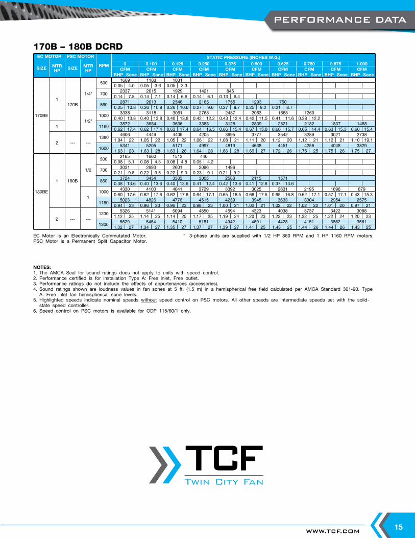
170BE
1170B
1/4*
5001669 1183 1031
0.05 4.0 0.05 3.6 0.05 3.3
7002337 2015 1929 1421 845
0.14 7.8 0.14 7.1 0.14 6.6 0.14 6.1 0.13 6.4
8602871 2613 2546 2185 1755 1293 750
0.25 10.8 0.26 10.8 0.26 10.6 0.27 9.6 0.27 8.7 0.25 9.2 0.21 8.7
1/2*1000
3338 3118 3061 2768 2437 2063 1663 12600.40 13.8 0.40 13.8 0.40 13.8 0.42 12.2 0.43 12.4 0.42 11.5 0.41 11.6 0.38 12.2
1 11603872 3684 3636 3388 3128 2839 2521 2182 1837 1488
0.62 17.4 0.62 17.4 0.63 17.4 0.64 16.5 0.66 15.4 0.67 15.8 0.66 15.7 0.65 14.4 0.63 15.3 0.60 15.4
2 --- ---1380
4606 4449 4409 4205 3995 3777 3542 3289 3021 27381.04 22 1.05 22 1.05 22 1.06 22 1.08 21 1.11 20 1.12 20 1.12 21 1.12 21 1.10 19.1
16005341 5205 5171 4997 4819 4638 4451 4256 4048 3829
1.63 28 1.63 28 1.63 28 1.64 28 1.66 28 1.69 27 1.72 26 1.75 25 1.75 26 1.75 27
180BE
1 180B
1/2
5002165 1660 1512 440
0.08 5.1 0.08 4.5 0.08 4.8 0.05 4.2
7003031 2693 2601 2096 1496
0.21 9.8 0.22 9.5 0.22 9.0 0.23 9.1 0.21 9.2
8603724 3454 3383 3005 2583 2115 1571
0.38 13.6 0.40 13.6 0.40 13.6 0.41 12.4 0.42 13.6 0.41 12.8 0.37 13.6
11000
4330 4100 4041 3729 3392 3025 2631 2195 1696 8790.60 17.6 0.62 17.6 0.62 17.6 0.64 17.1 0.65 16.5 0.66 17.5 0.65 16.8 0.62 17.1 0.57 17.1 0.43 15.3
11605023 4826 4776 4515 4239 3945 3633 3304 2954 2575
0.94 23 0.96 23 0.96 23 0.98 23 1.00 21 1.02 21 1.02 22 1.02 22 1.01 20 0.97 21
2 --- ---1230
5326 5141 5094 4850 4594 4323 4038 3737 3422 30881.12 25 1.14 25 1.14 25 1.17 25 1.19 24 1.20 23 1.22 23 1.22 25 1.22 24 1.20 23
13005629 5454 5410 5181 4942 4691 4428 4151 3862 3561
1.32 27 1.34 27 1.35 27 1.37 27 1.39 27 1.41 25 1.43 25 1.44 26 1.44 26 1.43 25
170B – 180B DCRD
EC Motor is an Electronically Commutated Motor. * 3-phase units are supplied with 1/2 HP 860 RPM and 1 HP 1160 RPM motors.PSC Motor is a Permanent Split Capacitor Motor.
PERFORMANCE DATA
Twin City Fan
Twin City Fan
TWIN CITY FAN - CATALOG 405016
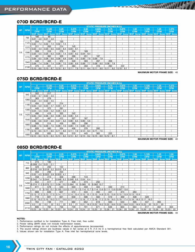
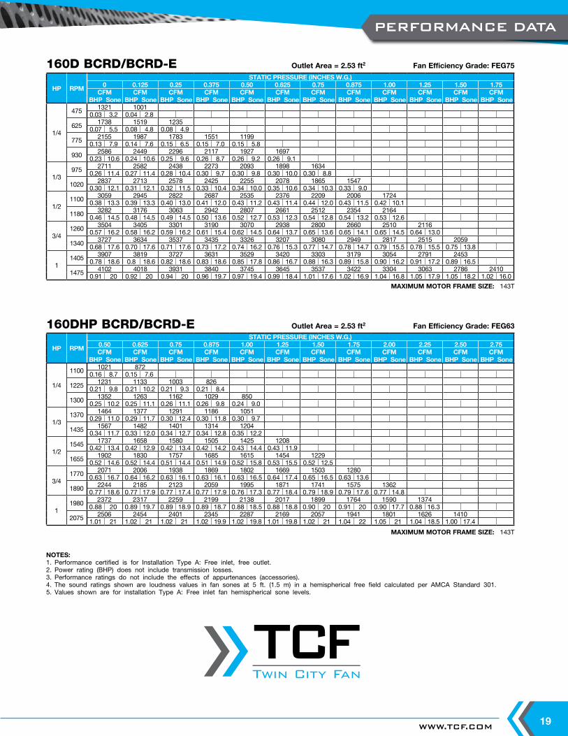
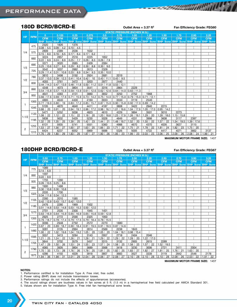
NOTES:1. Performance certified is for Installation Type A: Free inlet, free outlet.2. Power rating (BHP) does not include transmission losses.3. Performance ratings do not include the effects of appurtenances (accessories).4. The sound ratings shown are loudness values in fan sones at 5 ft. (1.5 m) in a hemispherical free field calculated per AMCA Standard 301.5. Values shown are for installation Type A: Free inlet fan hemispherical sone levels.
MAXIMUM MOTOR FRAME SIZE: 48
070D BCRD/BCRD-E
MAXIMUM MOTOR FRAME SIZE: 48
075D BCRD/BCRD-E
MAXIMUM MOTOR FRAME SIZE: 48
085D BCRD/BCRD-E
HP RPM
STATIC PRESSURE (INCHES W.G.)0 0.125 0.25 0.375 0.50 0.625 0.75 0.875 1.00 1.125 1.25 1.375
CFM CFM CFM CFM CFM CFM CFM CFM CFM CFM CFM CFMBHP Sone BHP Sone BHP Sone BHP Sone BHP Sone BHP Sone BHP Sone BHP Sone BHP Sone BHP Sone BHP Sone BHP Sone
1/4
795 180 850.01 4.0 0.01 4.0
1125 254 197 1200.02 7.4 0.02 7.4 0.02 7.4
1375 311 263 214 1450.03 4.4 0.03 6.5 0.03 8.4 0.03 9.1
1590 359 316 279 234 1690.05 5.5 0.05 6.3 0.05 7.4 0.05 8.2 0.04 8.4
1775 401 362 329 290 251 1870.06 6.5 0.06 6.6 0.06 6.8 0.06 7.3 0.06 7.9 0.06 7.9
1945 440 403 372 340 303 267 2060.08 7.4 0.08 7.4 0.08 7.0 0.08 6.9 0.08 7.7 0.08 8.0 0.08 7.8
2100 475 441 411 383 350 316 282 2220.10 8.6 0.10 8.7 0.10 8.1 0.11 7.9 0.11 8.4 0.11 9.0 0.11 9.2 0.10 9.1
HP RPM
STATIC PRESSURE (INCHES W.G.)0 0.125 0.25 0.375 0.50 0.625 0.75 0.875 1.00 1.125 1.25 1.375
CFM CFM CFM CFM CFM CFM CFM CFM CFM CFM CFM CFMBHP Sone BHP Sone BHP Sone BHP Sone BHP Sone BHP Sone BHP Sone BHP Sone BHP Sone BHP Sone BHP Sone BHP Sone
1/4
940 322 2170.02 3.7 0.02 3.5
1060 363 2780.02 4.4 0.02 4.5
1180 404 327 2140.03 5.0 0.03 4.7 0.03 4.7
1300 445 372 2910.04 5.5 0.04 5.2 0.05 5.3
1420 486 419 355 2420.05 6.0 0.06 6.0 0.06 5.6 0.06 5.4
1540 527 467 412 327 1670.06 6.6 0.07 6.6 0.07 6.2 0.08 6.5 0.06 5.6
1660 568 514 459 393 2960.08 7.5 0.09 7.5 0.09 7.0 0.09 7.4 0.09 6.7
1780 609 560 504 456 378 2600.10 8.5 0.11 8.5 0.11 8.0 0.11 7.9 0.12 8.4 0.11 7.5
1900 650 605 550 510 445 365 2250.12 9.4 0.13 9.4 0.14 9.2 0.14 8.7 0.14 9.2 0.14 8.9 0.12 8.1
HP RPM
STATIC PRESSURE (INCHES W.G.)0 0.125 0.25 0.375 0.50 0.625 0.75 0.875 1.00 1.125 1.25 1.50
CFM CFM CFM CFM CFM CFM CFM CFM CFM CFM CFM CFMBHP Sone BHP Sone BHP Sone BHP Sone BHP Sone BHP Sone BHP Sone BHP Sone BHP Sone BHP Sone BHP Sone BHP Sone
1/4
715 273 1800.009 2.4 0.01 2.1
860 329 260 1220.016 3.8 0.018 3.2 0.015 3.4
940 359 298 2040.02 4.5 0.022 3.9 0.023 4.1
1200 458 413 359 286 1430.042 7.4 0.044 7 0.048 6.3 0.048 6.6 0.04 6.4
1450 554 517 477 430 373 2920.074 11.5 0.076 12.1 0.08 10.2 0.084 10 0.085 10 0.082 10.7
1600 611 578 543 503 459 404 330 2140.1 15 0.102 15.1 0.105 13.9 0.111 13.1 0.114 12.7 0.114 13.6 0.111 13.8 0.097 13.6
1750 668 639 607 572 534 492 441 374 2840.13 17.3 0.13 17.5 0.14 17.1 0.14 15.4 0.15 15.1 0.15 14.8 0.15 15.8 0.15 15.9 0.13 15.9
1880 718 691 661 630 596 560 519 469 408 3280.16 19.3 0.16 19.3 0.17 19.9 0.17 17.1 0.18 17.1 0.18 17.2 0.19 16.5 0.19 17.4 0.18 18.3 0.17 18.3
2000 764 738 711 682 652 618 583 543 495 437 3650.2 22 0.2 22 0.2 22 0.2 21 0.21 19.3 0.22 19.2 0.22 18.6 0.22 18.6 0.22 19.9 0.22 20 0.21 20
2110 806 782 756 729 701 671 638 603 564 517 462 3040.23 24 0.23 24 0.23 24 0.24 23 0.24 21 0.25 21 0.26 21 0.26 20 0.26 21 0.26 22 0.26 22 0.23 22
PERFORMANCE DATA
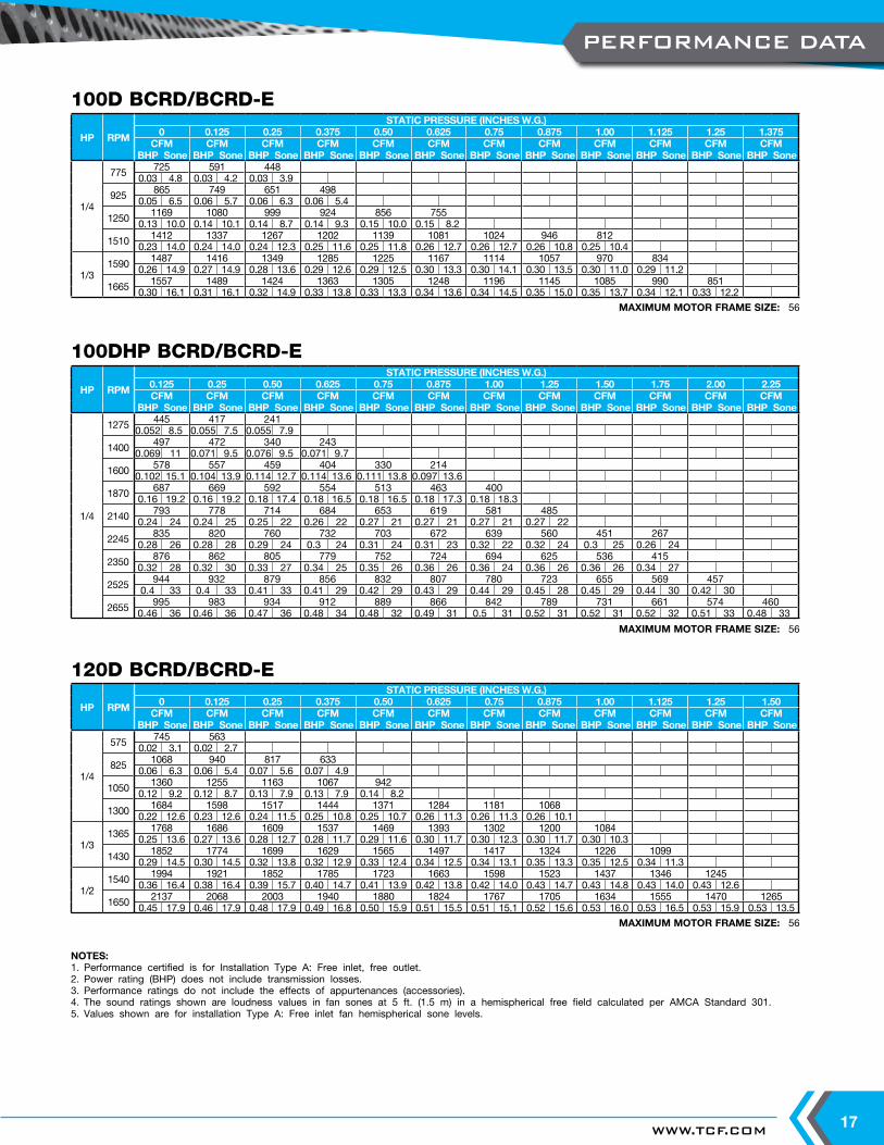
WWW.TCF.COM 17
NOTES:1. Performance certified is for Installation Type A: Free inlet, free outlet.2. Power rating (BHP) does not include transmission losses.3. Performance ratings do not include the effects of appurtenances (accessories).4. The sound ratings shown are loudness values in fan sones at 5 ft. (1.5 m) in a hemispherical free field calculated per AMCA Standard 301.5. Values shown are for installation Type A: Free inlet fan hemispherical sone levels.
MAXIMUM MOTOR FRAME SIZE: 56
100D BCRD/BCRD-E
MAXIMUM MOTOR FRAME SIZE: 56
100DHP BCRD/BCRD-E
MAXIMUM MOTOR FRAME SIZE: 56
120D BCRD/BCRD-E
HP RPM
STATIC PRESSURE (INCHES W.G.)0 0.125 0.25 0.375 0.50 0.625 0.75 0.875 1.00 1.125 1.25 1.375
CFM CFM CFM CFM CFM CFM CFM CFM CFM CFM CFM CFMBHP Sone BHP Sone BHP Sone BHP Sone BHP Sone BHP Sone BHP Sone BHP Sone BHP Sone BHP Sone BHP Sone BHP Sone
1/4
775 725 591 4480.03 4.8 0.03 4.2 0.03 3.9
925 865 749 651 4980.05 6.5 0.06 5.7 0.06 6.3 0.06 5.4
1250 1169 1080 999 924 856 7550.13 10.0 0.14 10.1 0.14 8.7 0.14 9.3 0.15 10.0 0.15 8.2
1510 1412 1337 1267 1202 1139 1081 1024 946 8120.23 14.0 0.24 14.0 0.24 12.3 0.25 11.6 0.25 11.8 0.26 12.7 0.26 12.7 0.26 10.8 0.25 10.4
1/31590 1487 1416 1349 1285 1225 1167 1114 1057 970 834
0.26 14.9 0.27 14.9 0.28 13.6 0.29 12.6 0.29 12.5 0.30 13.3 0.30 14.1 0.30 13.5 0.30 11.0 0.29 11.2
1665 1557 1489 1424 1363 1305 1248 1196 1145 1085 990 8510.30 16.1 0.31 16.1 0.32 14.9 0.33 13.8 0.33 13.3 0.34 13.6 0.34 14.5 0.35 15.0 0.35 13.7 0.34 12.1 0.33 12.2
HP RPM
STATIC PRESSURE (INCHES W.G.)0.125 0.25 0.50 0.625 0.75 0.875 1.00 1.25 1.50 1.75 2.00 2.25CFM CFM CFM CFM CFM CFM CFM CFM CFM CFM CFM CFM
BHP Sone BHP Sone BHP Sone BHP Sone BHP Sone BHP Sone BHP Sone BHP Sone BHP Sone BHP Sone BHP Sone BHP Sone
1/4
1275 445 417 2410.052 8.5 0.055 7.5 0.055 7.9
1400 497 472 340 2430.069 11 0.071 9.5 0.076 9.5 0.071 9.7
1600 578 557 459 404 330 2140.102 15.1 0.104 13.9 0.114 12.7 0.114 13.6 0.111 13.8 0.097 13.6
1870 687 669 592 554 513 463 4000.16 19.2 0.16 19.2 0.18 17.4 0.18 16.5 0.18 16.5 0.18 17.3 0.18 18.3
2140 793 778 714 684 653 619 581 4850.24 24 0.24 25 0.25 22 0.26 22 0.27 21 0.27 21 0.27 21 0.27 22
2245 835 820 760 732 703 672 639 560 451 2670.28 26 0.28 28 0.29 24 0.3 24 0.31 24 0.31 23 0.32 22 0.32 24 0.3 25 0.26 24
2350 876 862 805 779 752 724 694 625 536 4150.32 28 0.32 30 0.33 27 0.34 25 0.35 26 0.36 26 0.36 24 0.36 26 0.36 26 0.34 27
2525 944 932 879 856 832 807 780 723 655 569 4570.4 33 0.4 33 0.41 33 0.41 29 0.42 29 0.43 29 0.44 29 0.45 28 0.45 29 0.44 30 0.42 30
2655 995 983 934 912 889 866 842 789 731 661 574 4600.46 36 0.46 36 0.47 36 0.48 34 0.48 32 0.49 31 0.5 31 0.52 31 0.52 31 0.52 32 0.51 33 0.48 33
HP RPM
STATIC PRESSURE (INCHES W.G.)0 0.125 0.25 0.375 0.50 0.625 0.75 0.875 1.00 1.125 1.25 1.50
CFM CFM CFM CFM CFM CFM CFM CFM CFM CFM CFM CFMBHP Sone BHP Sone BHP Sone BHP Sone BHP Sone BHP Sone BHP Sone BHP Sone BHP Sone BHP Sone BHP Sone BHP Sone
1/4
575 745 5630.02 3.1 0.02 2.7
825 1068 940 817 6330.06 6.3 0.06 5.4 0.07 5.6 0.07 4.9
1050 1360 1255 1163 1067 9420.12 9.2 0.12 8.7 0.13 7.9 0.13 7.9 0.14 8.2
1300 1684 1598 1517 1444 1371 1284 1181 10680.22 12.6 0.23 12.6 0.24 11.5 0.25 10.8 0.25 10.7 0.26 11.3 0.26 11.3 0.26 10.1
1/31365 1768 1686 1609 1537 1469 1393 1302 1200 1084
0.25 13.6 0.27 13.6 0.28 12.7 0.28 11.7 0.29 11.6 0.30 11.7 0.30 12.3 0.30 11.7 0.30 10.3
1430 1852 1774 1699 1629 1565 1497 1417 1324 1226 10990.29 14.5 0.30 14.5 0.32 13.8 0.32 12.9 0.33 12.4 0.34 12.5 0.34 13.1 0.35 13.3 0.35 12.5 0.34 11.3
1/21540 1994 1921 1852 1785 1723 1663 1598 1523 1437 1346 1245
0.36 16.4 0.38 16.4 0.39 15.7 0.40 14.7 0.41 13.9 0.42 13.8 0.42 14.0 0.43 14.7 0.43 14.8 0.43 14.0 0.43 12.6
1650 2137 2068 2003 1940 1880 1824 1767 1705 1634 1555 1470 12650.45 17.9 0.46 17.9 0.48 17.9 0.49 16.8 0.50 15.9 0.51 15.5 0.51 15.1 0.52 15.6 0.53 16.0 0.53 16.5 0.53 15.9 0.53 13.5
PERFORMANCE DATA
TWIN CITY FAN - CATALOG 405018
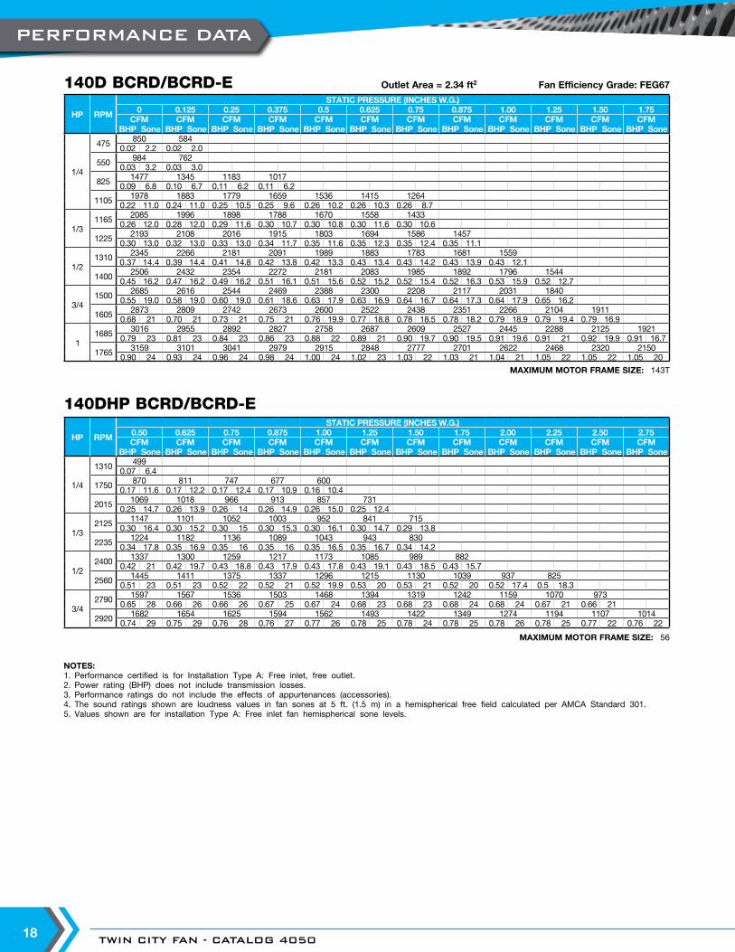
NOTES:1. Performance certified is for Installation Type A: Free inlet, free outlet.2. Power rating (BHP) does not include transmission losses.3. Performance ratings do not include the effects of appurtenances (accessories).4. The sound ratings shown are loudness values in fan sones at 5 ft. (1.5 m) in a hemispherical free field calculated per AMCA Standard 301.5. Values shown are for installation Type A: Free inlet fan hemispherical sone levels.
MAXIMUM MOTOR FRAME SIZE: 143T
140D BCRD/BCRD-E
MAXIMUM MOTOR FRAME SIZE: 56
Outlet Area = 2.34 ft2 Fan Efficiency Grade: FEG67
140DHP BCRD/BCRD-E
HP RPM
STATIC PRESSURE (INCHES W.G.)0 0.125 0.25 0.375 0.5 0.625 0.75 0.875 1.00 1.25 1.50 1.75
CFM CFM CFM CFM CFM CFM CFM CFM CFM CFM CFM CFMBHP Sone BHP Sone BHP Sone BHP Sone BHP Sone BHP Sone BHP Sone BHP Sone BHP Sone BHP Sone BHP Sone BHP Sone
1/4
475 850 5840.02 2.2 0.02 2.0
550 984 7620.03 3.2 0.03 3.0
825 1477 1345 1183 10170.09 6.8 0.10 6.7 0.11 6.2 0.11 6.2
1105 1978 1883 1779 1659 1536 1415 12640.22 11.0 0.24 11.0 0.25 10.5 0.25 9.6 0.26 10.2 0.26 10.3 0.26 8.7
1/31165 2085 1996 1898 1788 1670 1558 1433
0.26 12.0 0.28 12.0 0.29 11.6 0.30 10.7 0.30 10.8 0.30 11.6 0.30 10.6
1225 2193 2108 2016 1915 1803 1694 1586 14570.30 13.0 0.32 13.0 0.33 13.0 0.34 11.7 0.35 11.6 0.35 12.3 0.35 12.4 0.35 11.1
1/21310 2345 2266 2181 2091 1989 1883 1783 1681 1559
0.37 14.4 0.39 14.4 0.41 14.8 0.42 13.8 0.42 13.3 0.43 13.4 0.43 14.2 0.43 13.9 0.43 12.1
1400 2506 2432 2354 2272 2181 2083 1985 1892 1796 15440.45 16.2 0.47 16.2 0.49 16.2 0.51 16.1 0.51 15.6 0.52 15.2 0.52 15.4 0.52 16.3 0.53 15.9 0.52 12.7
3/41500 2685 2616 2544 2469 2388 2300 2208 2117 2031 1840
0.55 19.0 0.58 19.0 0.60 19.0 0.61 18.6 0.63 17.9 0.63 16.9 0.64 16.7 0.64 17.3 0.64 17.9 0.65 16.2
1605 2873 2809 2742 2673 2600 2522 2438 2351 2266 2104 19110.68 21 0.70 21 0.73 21 0.75 21 0.76 19.9 0.77 18.8 0.78 18.5 0.78 18.2 0.79 18.9 0.79 19.4 0.79 16.9
11685 3016 2955 2892 2827 2758 2687 2609 2527 2445 2288 2125 1921
0.79 23 0.81 23 0.84 23 0.86 23 0.88 22 0.89 21 0.90 19.7 0.90 19.5 0.91 19.6 0.91 21 0.92 19.9 0.91 16.7
1765 3159 3101 3041 2979 2915 2848 2777 2701 2622 2468 2320 21500.90 24 0.93 24 0.96 24 0.98 24 1.00 24 1.02 23 1.03 22 1.03 21 1.04 21 1.05 22 1.05 22 1.05 20
HP RPM
STATIC PRESSURE (INCHES W.G.)0.50 0.625 0.75 0.875 1.00 1.25 1.50 1.75 2.00 2.25 2.50 2.75CFM CFM CFM CFM CFM CFM CFM CFM CFM CFM CFM CFM
BHP Sone BHP Sone BHP Sone BHP Sone BHP Sone BHP Sone BHP Sone BHP Sone BHP Sone BHP Sone BHP Sone BHP Sone
1/4
1310 4990.07 6.4
1750 870 811 747 677 6000.17 11.6 0.17 12.2 0.17 12.4 0.17 10.9 0.16 10.4
2015 1069 1018 966 913 857 7310.25 14.7 0.26 13.9 0.26 14 0.26 14.9 0.26 15.0 0.25 12.4
1/32125 1147 1101 1052 1003 952 841 715
0.30 16.4 0.30 15.2 0.30 15 0.30 15.3 0.30 16.1 0.30 14.7 0.29 13.8
2235 1224 1182 1136 1089 1043 943 8300.34 17.8 0.35 16.9 0.35 16 0.35 16 0.35 16.5 0.35 16.7 0.34 14.2
1/22400 1337 1300 1259 1217 1173 1085 989 882
0.42 21 0.42 19.7 0.43 18.8 0.43 17.9 0.43 17.8 0.43 19.1 0.43 18.5 0.43 15.7
2560 1445 1411 1375 1337 1296 1215 1130 1039 937 8250.51 23 0.51 23 0.52 22 0.52 21 0.52 19.9 0.53 20 0.53 21 0.52 20 0.52 17.4 0.5 18.3
3/42790 1597 1567 1536 1503 1468 1394 1319 1242 1159 1070 973
0.65 28 0.66 26 0.66 26 0.67 25 0.67 24 0.68 23 0.68 23 0.68 24 0.68 24 0.67 21 0.66 21
2920 1682 1654 1625 1594 1562 1493 1422 1349 1274 1194 1107 10140.74 29 0.75 29 0.76 28 0.76 27 0.77 26 0.78 25 0.78 24 0.78 25 0.78 26 0.78 25 0.77 22 0.76 22
PERFORMANCE DATA
WWW.TCF.COM 19
NOTES:1. Performance certified is for Installation Type A: Free inlet, free outlet.2. Power rating (BHP) does not include transmission losses.3. Performance ratings do not include the effects of appurtenances (accessories).4. The sound ratings shown are loudness values in fan sones at 5 ft. (1.5 m) in a hemispherical free field calculated per AMCA Standard 301.5. Values shown are for installation Type A: Free inlet fan hemispherical sone levels.
MAXIMUM MOTOR FRAME SIZE: 143T
160D BCRD/BCRD-E Outlet Area = 2.53 ft2 Fan Efficiency Grade: FEG75
MAXIMUM MOTOR FRAME SIZE: 143T
160DHP BCRD/BCRD-E Outlet Area = 2.53 ft2 Fan Efficiency Grade: FEG63
HP RPM
STATIC PRESSURE (INCHES W.G.)0 0.125 0.25 0.375 0.50 0.625 0.75 0.875 1.00 1.25 1.50 1.75
CFM CFM CFM CFM CFM CFM CFM CFM CFM CFM CFM CFMBHP Sone BHP Sone BHP Sone BHP Sone BHP Sone BHP Sone BHP Sone BHP Sone BHP Sone BHP Sone BHP Sone BHP Sone
1/4
475 1321 10010.03 3.2 0.04 2.8
625 1738 1519 12350.07 5.5 0.08 4.8 0.08 4.9
775 2155 1987 1783 1551 11990.13 7.9 0.14 7.6 0.15 6.5 0.15 7.0 0.15 5.8
930 2586 2449 2296 2117 1927 16970.23 10.6 0.24 10.6 0.25 9.6 0.26 8.7 0.26 9.2 0.26 9.1
1/3975 2711 2582 2438 2273 2093 1898 1634
0.26 11.4 0.27 11.4 0.28 10.4 0.30 9.7 0.30 9.8 0.30 10.0 0.30 8.8
1020 2837 2713 2578 2425 2255 2078 1865 15470.30 12.1 0.31 12.1 0.32 11.5 0.33 10.4 0.34 10.0 0.35 10.6 0.34 10.3 0.33 9.0
1/21100 3059 2945 2822 2687 2535 2376 2209 2006 1724
0.38 13.3 0.39 13.3 0.40 13.0 0.41 12.0 0.43 11.2 0.43 11.4 0.44 12.0 0.43 11.5 0.42 10.1
1180 3282 3176 3063 2942 2807 2661 2512 2354 21640.46 14.5 0.48 14.5 0.49 14.5 0.50 13.6 0.52 12.7 0.53 12.3 0.54 12.8 0.54 13.2 0.53 12.6
3/41260 3504 3405 3301 3190 3070 2938 2800 2660 2510 2116
0.57 16.2 0.58 16.2 0.59 16.2 0.61 15.4 0.62 14.5 0.64 13.7 0.65 13.6 0.65 14.1 0.65 14.5 0.64 13.0
1340 3727 3634 3537 3435 3326 3207 3080 2949 2817 2515 20590.68 17.6 0.70 17.6 0.71 17.6 0.73 17.2 0.74 16.2 0.76 15.3 0.77 14.7 0.78 14.7 0.79 15.5 0.78 15.5 0.75 13.8
11405 3907 3819 3727 3631 3529 3420 3303 3179 3054 2791 2453
0.78 18.6 0.8 18.6 0.82 18.6 0.83 18.6 0.85 17.8 0.86 16.7 0.88 16.3 0.89 15.8 0.90 16.2 0.91 17.2 0.89 16.5
1475 4102 4018 3931 3840 3745 3645 3537 3422 3304 3063 2786 24100.91 20 0.92 20 0.94 20 0.96 19.7 0.97 19.4 0.99 18.4 1.01 17.6 1.02 16.9 1.04 16.8 1.05 17.9 1.05 18.2 1.02 16.0
HP RPM
STATIC PRESSURE (INCHES W.G.)0.50 0.625 0.75 0.875 1.00 1.25 1.50 1.75 2.00 2.25 2.50 2.75CFM CFM CFM CFM CFM CFM CFM CFM CFM CFM CFM CFM
BHP Sone BHP Sone BHP Sone BHP Sone BHP Sone BHP Sone BHP Sone BHP Sone BHP Sone BHP Sone BHP Sone BHP Sone
1/4
1100 1021 8720.16 8.7 0.15 7.6
1225 1231 1133 1003 8260.21 9.8 0.21 10.2 0.21 9.3 0.21 8.4
1300 1352 1263 1162 1029 8500.25 10.2 0.25 11.1 0.26 11.1 0.26 9.8 0.24 9.0
1/31370 1464 1377 1291 1186 1051
0.29 11.0 0.29 11.7 0.30 12.4 0.30 11.8 0.30 9.7
1435 1567 1482 1401 1314 12040.34 11.7 0.33 12.0 0.34 12.7 0.34 12.8 0.35 12.2
1/21545 1737 1658 1580 1505 1425 1208
0.42 13.4 0.42 12.9 0.42 13.4 0.42 14.2 0.43 14.4 0.43 11.9
1655 1902 1830 1757 1685 1615 1454 12290.52 14.6 0.52 14.4 0.51 14.4 0.51 14.9 0.52 15.8 0.53 15.5 0.52 12.5
3/41770 2071 2006 1938 1869 1802 1669 1503 1280
0.63 16.7 0.64 16.2 0.63 16.1 0.63 16.1 0.63 16.5 0.64 17.4 0.65 16.5 0.63 13.6
1890 2244 2185 2123 2059 1995 1871 1741 1575 13620.77 18.6 0.77 17.9 0.77 17.4 0.77 17.9 0.76 17.3 0.77 18.4 0.79 18.9 0.79 17.6 0.77 14.8
11980 2372 2317 2259 2199 2138 2017 1899 1764 1590 1374
0.88 20 0.89 19.7 0.89 18.9 0.89 18.7 0.88 18.5 0.88 18.8 0.90 20 0.91 20 0.90 17.7 0.88 16.3
2075 2506 2454 2401 2345 2287 2169 2057 1941 1801 1626 14101.01 21 1.02 21 1.02 21 1.02 19.9 1.02 19.8 1.01 19.8 1.02 21 1.04 22 1.05 21 1.04 18.5 1.00 17.4
PERFORMANCE DATA
Twin City Fan
Twin City Fan
TWIN CITY FAN - CATALOG 405020
NOTES:1. Performance certified is for Installation Type A: Free inlet, free outlet.2. Power rating (BHP) does not include transmission losses.3. Performance ratings do not include the effects of appurtenances (accessories).4. The sound ratings shown are loudness values in fan sones at 5 ft. (1.5 m) in a hemispherical free field calculated per AMCA Standard 301.5. Values shown are for installation Type A: Free inlet fan hemispherical sone levels.
MAXIMUM MOTOR FRAME SIZE: 145T
180D BCRD/BCRD-E Outlet Area = 3.37 ft2 Fan Efficiency Grade: FEG60
MAXIMUM MOTOR FRAME SIZE: 145T
180DHP BCRD/BCRD-E Outlet Area = 3.37 ft2 Fan Efficiency Grade: FEG67
HP RPM
STATIC PRESSURE (INCHES W.G.)0 0.125 0.25 0.375 0.5 0.75 1.00 1.25 1.50 1.75 2.00 2.25
CFM CFM CFM CFM CFM CFM CFM CFM CFM CFM CFM CFMBHP Sone BHP Sone BHP Sone BHP Sone BHP Sone BHP Sone BHP Sone BHP Sone BHP Sone BHP Sone BHP Sone BHP Sone
1/4
475 2320 1826 13760.08 5.5 0.09 4.2 0.10 4.5
575 2809 2389 2036 16320.15 8.0 0.16 6.5 0.17 6.4 0.17 6.2
660 3224 2857 2516 2225 18520.22 9.9 0.24 8.9 0.25 7.7 0.26 8.3 0.26 7.9
1/3690 3371 3020 2685 2409 2084
0.25 10.6 0.27 9.6 0.29 8.2 0.30 8.8 0.30 9.0
725 3542 3207 2882 2613 23280.29 11.4 0.31 10.8 0.33 8.9 0.34 9.3 0.35 10.0
1/2780 3810 3498 3192 2924 2681 2019
0.37 13.0 0.39 12.3 0.41 10.4 0.42 10 0.43 11.1 0.43 9.5
830 4055 3761 3472 3203 2977 24400.44 14.3 0.47 13.9 0.48 11.8 0.50 11.2 0.51 11.8 0.53 12.1
3/4890 4348 4073 3804 3541 3316 2864 2229
0.54 15.8 0.57 15.8 0.59 13.9 0.61 12.6 0.62 12.6 0.64 14.0 0.63 11.3
950 4641 4383 4131 3880 3652 3250 2752 19680.66 17.6 0.69 17.6 0.71 15.9 0.73 14.2 0.75 14.0 0.77 15.0 0.79 15.0 0.71 12.1
11000 4885 4640 4400 4160 3933 3550 3119 2540
0.77 19.0 0.80 19 0.83 17.2 0.85 15.7 0.87 15.0 0.90 15.8 0.92 17.0 0.89 14.2
1045 5105 4870 4640 4411 4187 3808 3422 2940 22150.88 20 0.91 20 0.94 19.1 0.96 17.2 0.98 16.1 1.01 16.6 1.04 17.9 1.05 17.0 0.95 14.2
1-1/21120 5471 5252 5036 4823 4610 4229 3894 3501 3010 2273
1.08 22 1.12 22 1.15 22 1.18 20 1.20 18.8 1.23 17.9 1.26 19.1 1.29 20 1.28 18.0 1.15 15.8
1195 5838 5632 5429 5230 5028 4649 4331 3998 3608 3117 23971.32 25 1.35 25 1.39 25 1.42 23 1.44 21 1.48 19.7 1.52 20 1.55 22 1.57 22 1.54 19.5 1.39 17.6
21255 6131 5935 5741 5551 5360 4988 4670 4370 4026 3627 3115
1.53 27 1.56 27 1.60 27 1.63 25 1.66 23 1.71 22 1.75 21 1.78 22 1.81 24 1.82 23 1.75 20
1315 6424 6237 6052 5869 5688 5326 5005 4722 4417 4071 3662 31371.76 29 1.80 29 1.83 29 1.87 27 1.90 26 1.95 23 1.99 23 2.03 23 2.06 25 2.09 26 2.08 24 1.99 21
HP RPM
STATIC PRESSURE (INCHES W.G.)0.50 0.75 1.00 1.25 1.50 1.75 2.00 2.25 2.50 2.75 3.00 3.25CFM CFM CFM CFM CFM CFM CFM CFM CFM CFM CFM CFM
BHP Sone BHP Sone BHP Sone BHP Sone BHP Sone BHP Sone BHP Sone BHP Sone BHP Sone BHP Sone BHP Sone BHP Sone
1/4
775 10890.14 6.9
890 15970.22 9.9
935 1755 12600.26 10.5 0.25 8.6
1/3980 1900 1488
0.30 10.8 0.30 10.8
1025 2035 17000.34 11.6 0.34 12.3
1/21105 2260 2010 1585
0.42 12.9 0.43 13.7 0.42 12.0
1185 2476 2280 1969 15020.51 14.8 0.53 14.8 0.53 15.3 0.50 12.0
3/41270 2701 2535 2300 1945 1451
0.63 16.9 0.64 15.9 0.65 16.9 0.65 15.6 0.59 12.8
1355 2925 2772 2590 2325 19500.76 18.7 0.78 17.4 0.79 17.5 0.79 18.4 0.78 15.5
11420 3096 2948 2792 2572 2270 1880
0.87 20 0.89 18.7 0.90 18.4 0.91 19.5 0.91 18.5 0.87 14.6
1490 3281 3135 2994 2814 2569 2238 18431.00 22 1.02 19.8 1.04 19.2 1.05 20 1.05 20 1.04 18.1 0.98 15.4
1-1/21595 3557 3413 3284 3143 2957 2718 2404 2046
1.21 25 1.24 22 1.26 21 1.28 21 1.29 22 1.29 22 1.28 20 1.22 17.0
1705 3844 3702 3579 3457 3315 3132 2905 2615 22891.47 29 1.50 26 1.53 24 1.55 23 1.57 24 1.58 25 1.58 25 1.57 22 1.52 19.5
21790 4065 3926 3804 3689 3568 3418 3230 3006 2721 2411 2004
1.70 33 1.73 28 1.76 26 1.78 25 1.81 25 1.82 25 1.83 27 1.82 27 1.81 25 1.76 21 1.63 20
1875 4286 4150 4028 3918 3807 3683 3527 3339 3119 2842 2546 21781.94 36 1.98 31 2.01 29 2.04 28 2.06 27 2.08 27 2.10 28 2.10 28 2.10 28 2.08 26 2.03 22 1.91 22
PERFORMANCE DATA
WWW.TCF.COM 21
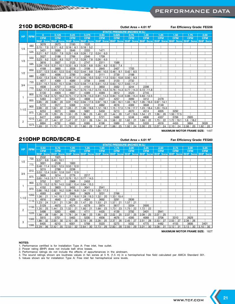
NOTES:1. Performance certified is for Installation Type A: Free inlet, free outlet.2. Power rating (BHP) does not include belt drive losses.3. Performance ratings do not include the effects of appurtenances in the airstream.4. The sound ratings shown are loudness values in fan sones at 5 ft. (1.5 m) in a hemispherical free field calculated per AMCA Standard 301.5. Values shown are for installation Type A: Free inlet fan hemispherical sone levels.
MAXIMUM MOTOR FRAME SIZE: 145T
210D BCRD/BCRD-E Outlet Area = 4.61 ft2 Fan Efficiency Grade: FEG56
MAXIMUM MOTOR FRAME SIZE: 182T
210DHP BCRD/BCRD-E Outlet Area = 4.61 ft2 Fan Efficiency Grade: FEG60
HP RPM
STATIC PRESSURE (INCHES W.G.)0 0.125 0.25 0.375 0.50 0.625 0.75 1.00 1.25 1.50 1.75 2.00
CFM CFM CFM CFM CFM CFM CFM CFM CFM CFM CFM CFMBHP Sone BHP Sone BHP Sone BHP Sone BHP Sone BHP Sone BHP Sone BHP Sone BHP Sone BHP Sone BHP Sone BHP Sone
1/4480 3078 2673 2193 1535
0.15 7.0 0.17 6.2 0.18 6.1 0.18 5.2
535 3431 3080 2646 2203 14710.21 8.7 0.23 7.9 0.25 6.9 0.26 7.2 0.24 6.3
1/3550 3527 3188 2766 2346 1709
0.23 9.2 0.25 8.5 0.27 7.2 0.28 7.8 0.26 6.5
595 3816 3507 3125 2747 2311 15880.29 10.5 0.31 10.1 0.33 8.3 0.35 8.8 0.35 8.2 0.32 7.4
1/2650 4168 3890 3558 3199 2845 2407 1705
0.37 12.5 0.40 12.5 0.42 10.2 0.44 9.8 0.46 10.5 0.46 9.1 0.42 8.5
680 4361 4096 3789 3439 3111 2739 21880.43 13.4 0.45 13.4 0.48 11.4 0.50 10.5 0.52 11.3 0.53 10.8 0.50 9.3
3/4720 4617 4369 4089 3758 3446 3120 2732
0.51 15.1 0.53 15.1 0.56 13.3 0.59 11.6 0.61 12.2 0.63 12.7 0.63 11.2
770 4938 4707 4452 4154 3850 3562 3244 22980.62 17.0 0.65 17.0 0.68 15.7 0.70 13.7 0.73 13.3 0.76 14.3 0.77 14.3 0.72 11.8
1800 5130 4909 4667 4389 4089 3812 3520 2745
0.70 18.2 0.72 18.2 0.75 17.2 0.78 15.0 0.81 14.3 0.84 14.8 0.86 15.4 0.83 12.5
855 5483 5277 5054 4808 4527 4257 3999 3412 24780.85 20 0.88 20 0.91 19.2 0.94 17.6 0.97 16.1 1.00 16.1 1.03 16.7 1.05 16.3 0.97 14.1
1-1/2900 5772 5577 5368 5141 4882 4616 4369 3848 3148
0.99 22 1.02 22 1.05 21 1.09 19.8 1.12 18.1 1.15 17.3 1.19 17.7 1.23 18.4 1.20 15.3
975 6253 6073 5884 5681 5459 5213 4970 4514 4005 32921.26 25 1.29 25 1.33 25 1.36 23 1.40 22 1.44 20 1.47 19.6 1.54 21 1.56 20 1.50 17.5
21010 6477 6304 6122 5929 5721 5488 5248 4806 4337 3766 2905
1.40 27 1.44 27 1.47 27 1.51 26 1.54 24 1.58 22 1.62 21 1.69 22 1.73 22 1.72 19.1 1.6 18.2
1075 6894 6732 6563 6385 6196 5989 5765 5333 4918 4455 3864 30281.69 31 1.73 31 1.76 31 1.80 29 1.84 27 1.88 25 1.92 24 2.00 23 2.07 24 2.10 24 2.06 20 1.92 20
HP RPM
STATIC PRESSURE (INCHES W.G.)0.50 0.75 1.00 1.25 1.50 1.75 2.00 2.25 2.50 2.75 3.00 3.25CFM CFM CFM CFM CFM CFM CFM CFM CFM CFM CFM CFM
BHP Sone BHP Sone BHP Sone BHP Sone BHP Sone BHP Sone BHP Sone BHP Sone BHP Sone BHP Sone BHP Sone BHP Sone
1/2700 2532 1925
0.37 9.9 0.40 10.1
775 3001 2538 19000.48 11.4 0.52 12.5 0.53 12.0
3/4810 3215 2788 2238
0.53 12.4 0.59 12.8 0.61 12.9
875 3605 3214 2779 22170.65 14.5 0.71 13.7 0.76 15.1 0.77 14.5
1900 3752 3371 2968 2453
0.70 15.2 0.76 14.5 0.82 15.4 0.84 15.3
970 4152 3803 3452 3041 25410.86 18.2 0.92 16.2 0.99 16.8 1.04 17.9 1.05 17.3
1-1/21050 4593 4287 3960 3629 3231 2766
1.06 21 1.14 19.1 1.21 18.6 1.28 19.3 1.32 20 1.33 19.4
1110 4916 4640 4329 4024 3692 3291 28361.23 24 1.31 21 1.39 20 1.47 20 1.53 21 1.57 21 1.57 21
21150 5129 4870 4574 4278 3974 3617 3204 2695
1.35 25 1.44 23 1.52 21 1.60 21 1.68 23 1.73 23 1.75 22 1.72 22
1220 5498 5263 4995 4711 4435 4139 3792 3401 29411.58 28 1.69 26 1.78 24 1.86 23 1.95 23 2.02 25 2.07 25 2.09 25 2.07 25
31300 5915 5701 5463 5200 4936 4676 4395 4069 3706 3310 2629
1.88 32 2.00 30 2.10 28 2.19 26 2.28 25 2.37 26 2.45 27 2.51 28 2.53 27 2.53 27 2.39 26
1395 6405 6210 6001 5768 5520 5275 5032 4775 4482 4155 3806 34012.29 36 2.42 35 2.53 32 2.64 30 2.73 29 2.83 28 2.93 29 3.01 30 3.08 31 3.12 31 3.13 30 3.10 30
PERFORMANCE DATA
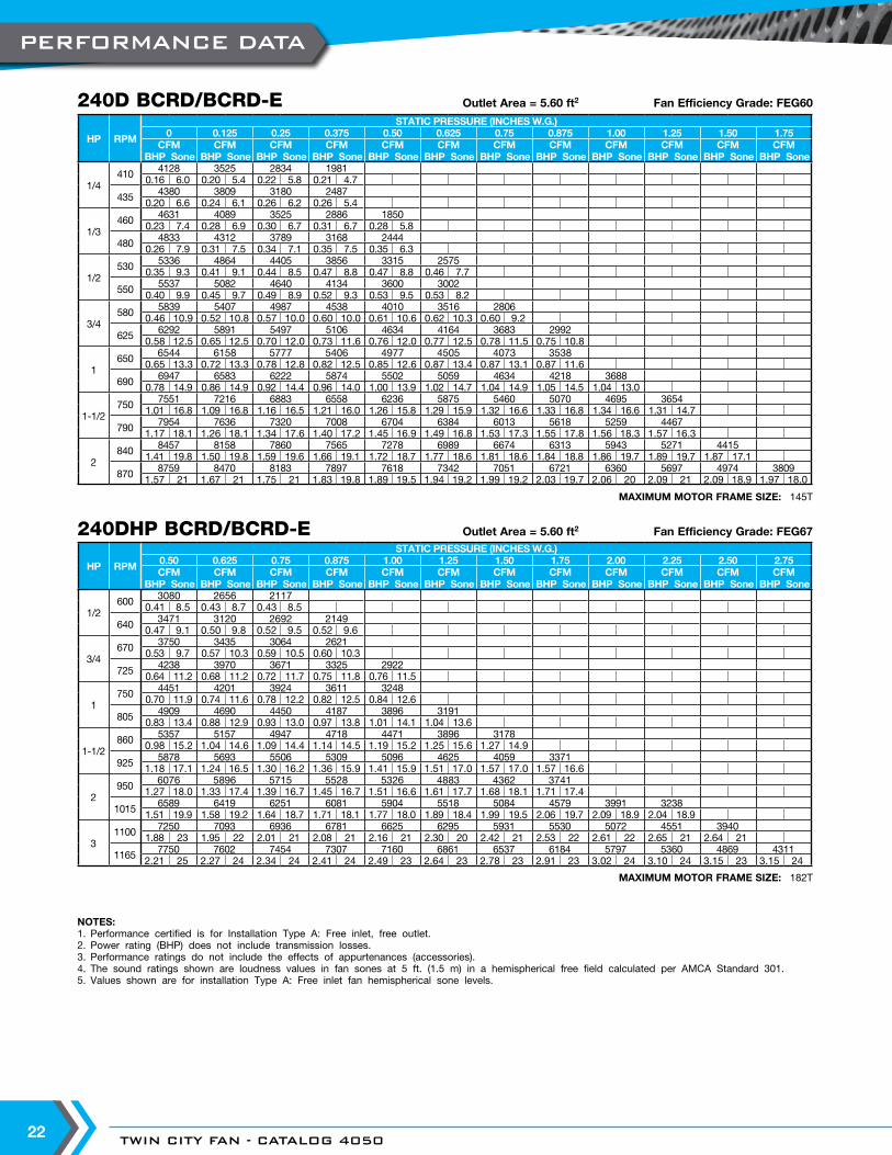
TWIN CITY FAN - CATALOG 405022
NOTES:1. Performance certified is for Installation Type A: Free inlet, free outlet.2. Power rating (BHP) does not include transmission losses.3. Performance ratings do not include the effects of appurtenances (accessories).4. The sound ratings shown are loudness values in fan sones at 5 ft. (1.5 m) in a hemispherical free field calculated per AMCA Standard 301.5. Values shown are for installation Type A: Free inlet fan hemispherical sone levels.
MAXIMUM MOTOR FRAME SIZE: 145T
240D BCRD/BCRD-E Outlet Area = 5.60 ft2 Fan Efficiency Grade: FEG60
MAXIMUM MOTOR FRAME SIZE: 182T
240DHP BCRD/BCRD-E Outlet Area = 5.60 ft2 Fan Efficiency Grade: FEG67
HP RPM
STATIC PRESSURE (INCHES W.G.)0 0.125 0.25 0.375 0.50 0.625 0.75 0.875 1.00 1.25 1.50 1.75
CFM CFM CFM CFM CFM CFM CFM CFM CFM CFM CFM CFMBHP Sone BHP Sone BHP Sone BHP Sone BHP Sone BHP Sone BHP Sone BHP Sone BHP Sone BHP Sone BHP Sone BHP Sone
1/4410 4128 3525 2834 1981
0.16 6.0 0.20 5.4 0.22 5.8 0.21 4.7
435 4380 3809 3180 24870.20 6.6 0.24 6.1 0.26 6.2 0.26 5.4
1/3460 4631 4089 3525 2886 1850
0.23 7.4 0.28 6.9 0.30 6.7 0.31 6.7 0.28 5.8
480 4833 4312 3789 3168 24440.26 7.9 0.31 7.5 0.34 7.1 0.35 7.5 0.35 6.3
1/2530 5336 4864 4405 3856 3315 2575
0.35 9.3 0.41 9.1 0.44 8.5 0.47 8.8 0.47 8.8 0.46 7.7
550 5537 5082 4640 4134 3600 30020.40 9.9 0.45 9.7 0.49 8.9 0.52 9.3 0.53 9.5 0.53 8.2
3/4580 5839 5407 4987 4538 4010 3516 2806
0.46 10.9 0.52 10.8 0.57 10.0 0.60 10.0 0.61 10.6 0.62 10.3 0.60 9.2
625 6292 5891 5497 5106 4634 4164 3683 29920.58 12.5 0.65 12.5 0.70 12.0 0.73 11.6 0.76 12.0 0.77 12.5 0.78 11.5 0.75 10.8
1650 6544 6158 5777 5406 4977 4505 4073 3538
0.65 13.3 0.72 13.3 0.78 12.8 0.82 12.5 0.85 12.6 0.87 13.4 0.87 13.1 0.87 11.6
690 6947 6583 6222 5874 5502 5059 4634 4218 36880.78 14.9 0.86 14.9 0.92 14.4 0.96 14.0 1.00 13.9 1.02 14.7 1.04 14.9 1.05 14.5 1.04 13.0
1-1/2750 7551 7216 6883 6558 6236 5875 5460 5070 4695 3654
1.01 16.8 1.09 16.8 1.16 16.5 1.21 16.0 1.26 15.8 1.29 15.9 1.32 16.6 1.33 16.8 1.34 16.6 1.31 14.7
790 7954 7636 7320 7008 6704 6384 6013 5618 5259 44671.17 18.1 1.26 18.1 1.34 17.6 1.40 17.2 1.45 16.9 1.49 16.8 1.53 17.3 1.55 17.8 1.56 18.3 1.57 16.3
2840 8457 8158 7860 7565 7278 6989 6674 6313 5943 5271 4415
1.41 19.8 1.50 19.8 1.59 19.6 1.66 19.1 1.72 18.7 1.77 18.6 1.81 18.6 1.84 18.8 1.86 19.7 1.89 19.7 1.87 17.1
870 8759 8470 8183 7897 7618 7342 7051 6721 6360 5697 4974 38091.57 21 1.67 21 1.75 21 1.83 19.8 1.89 19.5 1.94 19.2 1.99 19.2 2.03 19.7 2.06 20 2.09 21 2.09 18.9 1.97 18.0
HP RPM
STATIC PRESSURE (INCHES W.G.)0.50 0.625 0.75 0.875 1.00 1.25 1.50 1.75 2.00 2.25 2.50 2.75CFM CFM CFM CFM CFM CFM CFM CFM CFM CFM CFM CFM
BHP Sone BHP Sone BHP Sone BHP Sone BHP Sone BHP Sone BHP Sone BHP Sone BHP Sone BHP Sone BHP Sone BHP Sone
1/2600 3080 2656 2117
0.41 8.5 0.43 8.7 0.43 8.5
640 3471 3120 2692 21490.47 9.1 0.50 9.8 0.52 9.5 0.52 9.6
3/4670 3750 3435 3064 2621
0.53 9.7 0.57 10.3 0.59 10.5 0.60 10.3
725 4238 3970 3671 3325 29220.64 11.2 0.68 11.2 0.72 11.7 0.75 11.8 0.76 11.5
1750 4451 4201 3924 3611 3248
0.70 11.9 0.74 11.6 0.78 12.2 0.82 12.5 0.84 12.6
805 4909 4690 4450 4187 3896 31910.83 13.4 0.88 12.9 0.93 13.0 0.97 13.8 1.01 14.1 1.04 13.6
1-1/2860 5357 5157 4947 4718 4471 3896 3178
0.98 15.2 1.04 14.6 1.09 14.4 1.14 14.5 1.19 15.2 1.25 15.6 1.27 14.9
925 5878 5693 5506 5309 5096 4625 4059 33711.18 17.1 1.24 16.5 1.30 16.2 1.36 15.9 1.41 15.9 1.51 17.0 1.57 17.0 1.57 16.6
2950 6076 5896 5715 5528 5326 4883 4362 3741
1.27 18.0 1.33 17.4 1.39 16.7 1.45 16.7 1.51 16.6 1.61 17.7 1.68 18.1 1.71 17.4
1015 6589 6419 6251 6081 5904 5518 5084 4579 3991 32381.51 19.9 1.58 19.2 1.64 18.7 1.71 18.1 1.77 18.0 1.89 18.4 1.99 19.5 2.06 19.7 2.09 18.9 2.04 18.9
31100 7250 7093 6936 6781 6625 6295 5931 5530 5072 4551 3940
1.88 23 1.95 22 2.01 21 2.08 21 2.16 21 2.30 20 2.42 21 2.53 22 2.61 22 2.65 21 2.64 21
1165 7750 7602 7454 7307 7160 6861 6537 6184 5797 5360 4869 43112.21 25 2.27 24 2.34 24 2.41 24 2.49 23 2.64 23 2.78 23 2.91 23 3.02 24 3.10 24 3.15 23 3.15 24
PERFORMANCE DATA
WWW.TCF.COM 23
NOTES:1. Performance certified is for Installation Type A: Free inlet, free outlet.2. Power rating (BHP) does not include transmission losses.3. Performance ratings do not include the effects of appurtenances (accessories).4. The sound ratings shown are loudness values in fan sones at 5 ft. (1.5 m) in a hemispherical free field calculated per AMCA Standard 301.5. Values shown are for installation Type A: Free inlet fan hemispherical sone levels.
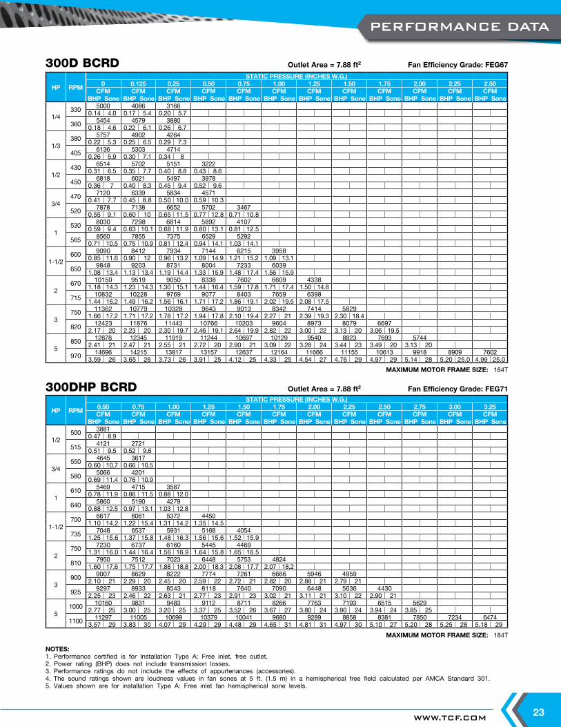
MAXIMUM MOTOR FRAME SIZE: 184T
300D BCRD Outlet Area = 7.88 ft2 Fan Efficiency Grade: FEG67
MAXIMUM MOTOR FRAME SIZE: 184T
300DHP BCRD Outlet Area = 7.88 ft2 Fan Efficiency Grade: FEG71
HP RPM
STATIC PRESSURE (INCHES W.G.)0.50 0.75 1.00 1.25 1.50 1.75 2.00 2.25 2.50 2.75 3.00 3.25CFM CFM CFM CFM CFM CFM CFM CFM CFM CFM CFM CFM
BHP Sone BHP Sone BHP Sone BHP Sone BHP Sone BHP Sone BHP Sone BHP Sone BHP Sone BHP Sone BHP Sone BHP Sone
1/2500 3881
0.47 8.9
515 4121 27210.51 9.5 0.52 9.6
3/4550 4645 3617
0.60 10.7 0.66 10.5
580 5066 42010.69 11.4 0.76 10.9
1610 5469 4715 3587
0.78 11.9 0.86 11.5 0.88 12.0
640 5860 5190 42790.88 12.5 0.97 13.1 1.03 12.8
1-1/2700 6617 6061 5372 4450
1.10 14.2 1.22 15.4 1.31 14.2 1.35 14.5
735 7048 6537 5931 5168 40541.25 15.6 1.37 15.8 1.48 16.3 1.56 15.6 1.52 15.9
2750 7230 6737 6160 5445 4469
1.31 16.0 1.44 16.4 1.56 16.9 1.64 15.8 1.65 16.5
810 7950 7512 7023 6448 5753 48241.60 17.6 1.75 17.7 1.88 18.8 2.00 18.3 2.08 17.7 2.07 18.2
3900 9007 8629 8222 7774 7261 6666 5946 4959
2.10 21 2.29 20 2.45 20 2.59 22 2.72 21 2.82 20 2.88 21 2.79 21
925 9297 8933 8543 8118 7640 7090 6448 5636 44302.25 23 2.46 22 2.63 21 2.77 23 2.91 23 3.02 21 3.11 21 3.10 22 2.90 21
51000 10160 9831 9483 9112 8711 8266 7763 7193 6515 5629
2.77 25 3.00 25 3.20 25 3.37 25 3.52 26 3.67 27 3.80 24 3.90 24 3.94 24 3.85 25
1100 11297 11005 10699 10379 10041 9680 9289 8858 8381 7850 7234 64743.57 29 3.83 30 4.07 29 4.29 29 4.48 29 4.65 31 4.81 31 4.97 30 5.10 27 5.20 28 5.25 28 5.18 29
HP RPM
STATIC PRESSURE (INCHES W.G.)0 0.125 0.25 0.50 0.75 1.00 1.25 1.50 1.75 2.00 2.25 2.50
CFM CFM CFM CFM CFM CFM CFM CFM CFM CFM CFM CFMBHP Sone BHP Sone BHP Sone BHP Sone BHP Sone BHP Sone BHP Sone BHP Sone BHP Sone BHP Sone BHP Sone BHP Sone
1/4330 5000 4086 3166
0.14 4.0 0.17 5.4 0.20 5.7
360 5454 4579 38800.18 4.6 0.22 6.1 0.26 6.7
1/3380 5757 4902 4264
0.22 5.3 0.25 6.5 0.29 7.3
405 6136 5303 47140.26 5.9 0.30 7.1 0.34 8
1/2430 6514 5702 5151 3222
0.31 6.5 0.35 7.7 0.40 8.8 0.43 8.6
450 6818 6021 5497 39780.36 7 0.40 8.3 0.45 9.4 0.52 9.6
3/4470 7120 6339 5834 4571
0.41 7.7 0.45 8.8 0.50 10.0 0.59 10.3
520 7878 7138 6652 5702 34670.55 9.1 0.60 10 0.65 11.5 0.77 12.8 0.71 10.8
1530 8030 7298 6814 5892 4107
0.59 9.4 0.63 10.1 0.68 11.9 0.80 13.1 0.81 12.5
565 8560 7855 7375 6529 52920.71 10.5 0.75 10.9 0.81 12.4 0.94 14.1 1.03 14.1
1-1/2600 9090 8412 7934 7144 6215 3958
0.85 11.6 0.90 12 0.96 13.2 1.09 14.9 1.21 15.2 1.09 13.1
650 9848 9203 8731 8004 7233 60391.08 13.4 1.13 13.4 1.19 14.4 1.33 15.9 1.48 17.4 1.56 15.9
2670 10150 9519 9050 8338 7602 6609 4338
1.18 14.3 1.23 14.3 1.30 15.1 1.44 16.4 1.59 17.8 1.71 17.4 1.50 14.8
715 10832 10228 9769 9077 8403 7659 63981.44 16.2 1.49 16.2 1.56 16.1 1.71 17.2 1.86 19.1 2.02 19.5 2.08 17.5
3750 11362 10779 10328 9643 9013 8342 7414 5829
1.66 17.2 1.71 17.2 1.78 17.2 1.94 17.8 2.10 19.4 2.27 21 2.39 19.3 2.30 18.4
820 12423 11876 11443 10766 10203 9604 8973 8079 66972.17 20 2.23 20 2.30 19.7 2.46 19.1 2.64 19.9 2.82 22 3.00 22 3.13 20 3.06 19.5
5850 12878 12345 11919 11244 10697 10129 9540 8823 7693 5744
2.41 21 2.47 21 2.55 21 2.72 20 2.90 21 3.09 22 3.28 24 3.44 23 3.49 20 3.13 20
970 14696 14215 13817 13157 12637 12164 11666 11155 10613 9918 8909 76023.59 26 3.65 26 3.73 26 3.91 25 4.12 25 4.33 25 4.54 27 4.76 29 4.97 29 5.14 28 5.20 25.0 4.99 25.0
PERFORMANCE DATA
TWIN CITY FAN - CATALOG 405024
NOTES:1. Performance certified is for Installation Type A: Free inlet, free outlet.2. Power rating (BHP) does not include transmission losses.3. Performance ratings do not include the effects of appurtenances (accessories).4. The sound ratings shown are loudness values in fan sones at 5 ft. (1.5 m) in a hemispherical free field calculated per AMCA Standard 301.5. Type A: Free inlet fan hemispherical sone levels.
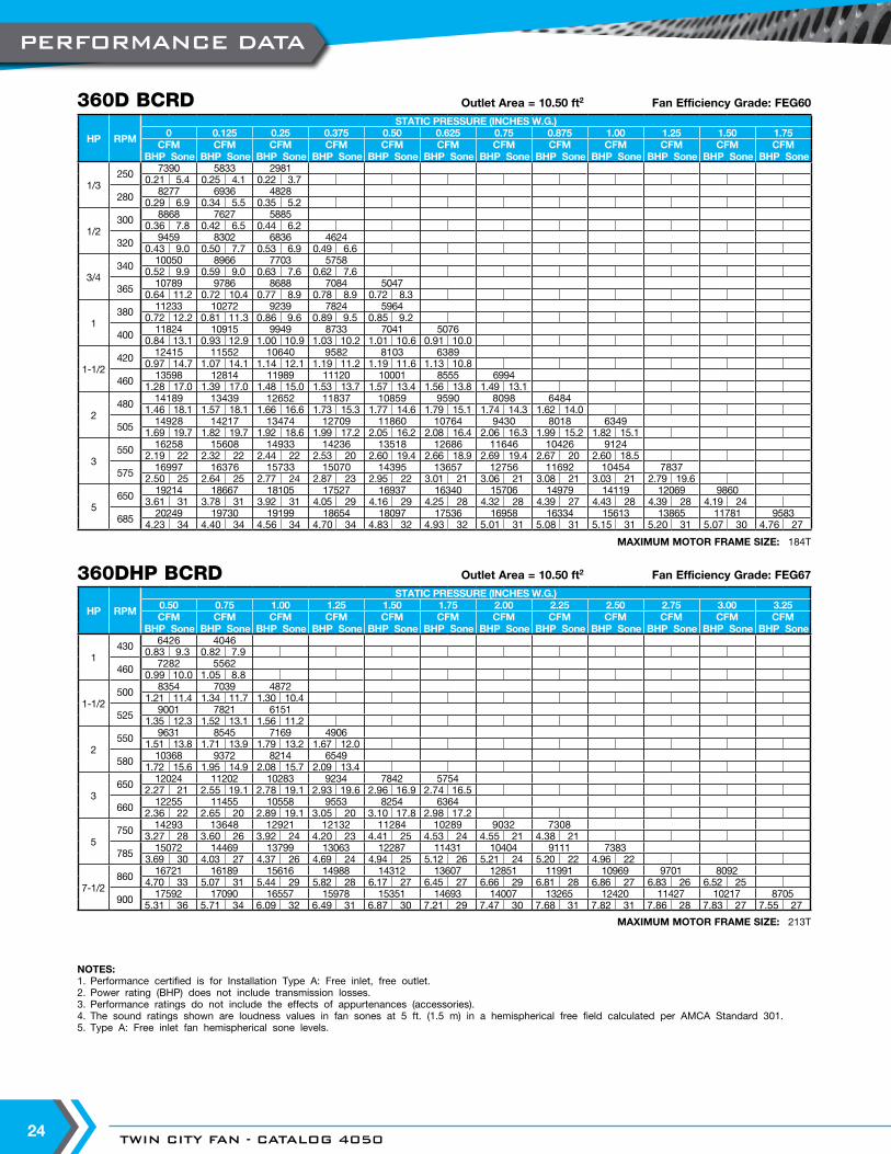
MAXIMUM MOTOR FRAME SIZE: 184T
360D BCRD Outlet Area = 10.50 ft2 Fan Efficiency Grade: FEG60
MAXIMUM MOTOR FRAME SIZE: 213T
360DHP BCRD Outlet Area = 10.50 ft2 Fan Efficiency Grade: FEG67
HP RPM
STATIC PRESSURE (INCHES W.G.)0.50 0.75 1.00 1.25 1.50 1.75 2.00 2.25 2.50 2.75 3.00 3.25CFM CFM CFM CFM CFM CFM CFM CFM CFM CFM CFM CFM
BHP Sone BHP Sone BHP Sone BHP Sone BHP Sone BHP Sone BHP Sone BHP Sone BHP Sone BHP Sone BHP Sone BHP Sone
1430 6426 4046
0.83 9.3 0.82 7.9
460 7282 55620.99 10.0 1.05 8.8
1-1/2500 8354 7039 4872
1.21 11.4 1.34 11.7 1.30 10.4
525 9001 7821 61511.35 12.3 1.52 13.1 1.56 11.2
2550 9631 8545 7169 4906
1.51 13.8 1.71 13.9 1.79 13.2 1.67 12.0
580 10368 9372 8214 65491.72 15.6 1.95 14.9 2.08 15.7 2.09 13.4
3650 12024 11202 10283 9234 7842 5754
2.27 21 2.55 19.1 2.78 19.1 2.93 19.6 2.96 16.9 2.74 16.5
660 12255 11455 10558 9553 8254 63642.36 22 2.65 20 2.89 19.1 3.05 20 3.10 17.8 2.98 17.2
5750 14293 13648 12921 12132 11284 10289 9032 7308
3.27 28 3.60 26 3.92 24 4.20 23 4.41 25 4.53 24 4.55 21 4.38 21
785 15072 14469 13799 13063 12287 11431 10404 9111 73833.69 30 4.03 27 4.37 26 4.69 24 4.94 25 5.12 26 5.21 24 5.20 22 4.96 22
7-1/2860 16721 16189 15616 14988 14312 13607 12851 11991 10969 9701 8092
4.70 33 5.07 31 5.44 29 5.82 28 6.17 27 6.45 27 6.66 29 6.81 28 6.86 27 6.83 26 6.52 25
900 17592 17090 16557 15978 15351 14693 14007 13265 12420 11427 10217 87055.31 36 5.71 34 6.09 32 6.49 31 6.87 30 7.21 29 7.47 30 7.68 31 7.82 31 7.86 28 7.83 27 7.55 27
HP RPM
STATIC PRESSURE (INCHES W.G.)0 0.125 0.25 0.375 0.50 0.625 0.75 0.875 1.00 1.25 1.50 1.75
CFM CFM CFM CFM CFM CFM CFM CFM CFM CFM CFM CFMBHP Sone BHP Sone BHP Sone BHP Sone BHP Sone BHP Sone BHP Sone BHP Sone BHP Sone BHP Sone BHP Sone BHP Sone
1/3250 7390 5833 2981
0.21 5.4 0.25 4.1 0.22 3.7
280 8277 6936 48280.29 6.9 0.34 5.5 0.35 5.2
1/2300 8868 7627 5885
0.36 7.8 0.42 6.5 0.44 6.2
320 9459 8302 6836 46240.43 9.0 0.50 7.7 0.53 6.9 0.49 6.6
3/4340 10050 8966 7703 5758
0.52 9.9 0.59 9.0 0.63 7.6 0.62 7.6
365 10789 9786 8688 7084 50470.64 11.2 0.72 10.4 0.77 8.9 0.78 8.9 0.72 8.3
1380 11233 10272 9239 7824 5964
0.72 12.2 0.81 11.3 0.86 9.6 0.89 9.5 0.85 9.2
400 11824 10915 9949 8733 7041 50760.84 13.1 0.93 12.9 1.00 10.9 1.03 10.2 1.01 10.6 0.91 10.0
1-1/2420 12415 11552 10640 9582 8103 6389
0.97 14.7 1.07 14.1 1.14 12.1 1.19 11.2 1.19 11.6 1.13 10.8
460 13598 12814 11989 11120 10001 8555 69941.28 17.0 1.39 17.0 1.48 15.0 1.53 13.7 1.57 13.4 1.56 13.8 1.49 13.1
2480 14189 13439 12652 11837 10859 9590 8098 6484
1.46 18.1 1.57 18.1 1.66 16.6 1.73 15.3 1.77 14.6 1.79 15.1 1.74 14.3 1.62 14.0
505 14928 14217 13474 12709 11860 10764 9430 8018 63491.69 19.7 1.82 19.7 1.92 18.6 1.99 17.2 2.05 16.2 2.08 16.4 2.06 16.3 1.99 15.2 1.82 15.1
3550 16258 15608 14933 14236 13518 12686 11646 10426 9124
2.19 22 2.32 22 2.44 22 2.53 20 2.60 19.4 2.66 18.9 2.69 19.4 2.67 20 2.60 18.5
575 16997 16376 15733 15070 14395 13657 12756 11692 10454 78372.50 25 2.64 25 2.77 24 2.87 23 2.95 22 3.01 21 3.06 21 3.08 21 3.03 21 2.79 19.6
5650 19214 18667 18105 17527 16937 16340 15706 14979 14119 12069 9860
3.61 31 3.78 31 3.92 31 4.05 29 4.16 29 4.25 28 4.32 28 4.39 27 4.43 28 4.39 28 4.19 24
685 20249 19730 19199 18654 18097 17536 16958 16334 15613 13865 11781 95834.23 34 4.40 34 4.56 34 4.70 34 4.83 32 4.93 32 5.01 31 5.08 31 5.15 31 5.20 31 5.07 30 4.76 27
PERFORMANCE DATA
WWW.TCF.COM 25
NOTES:1. Performance certified is for Installation Type A: Free inlet, free outlet.2. Power rating (BHP) does not include transmission losses.3. Performance ratings do not include the effects of appurtenances (accessories).4. The sound ratings shown are loudness values in fan sones at 5 ft. (1.5 m) in a hemispherical free field calculated per AMCA Standard 301.5. Values shown are for installation Type A: Free inlet fan hemispherical sone levels.
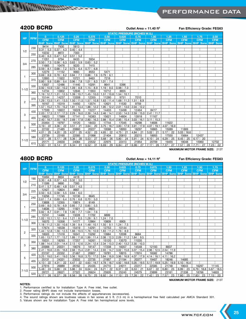
MAXIMUM MOTOR FRAME SIZE: 213T
420D BCRD Outlet Area = 11.40 ft2 Fan Efficiency Grade: FEG63
MAXIMUM MOTOR FRAME SIZE: 213T
480D BCRD Outlet Area = 14.11 ft2 Fan Efficiency Grade: FEG63
HP RPM
STATIC PRESSURE (INCHES W.G.)0 0.125 0.25 0.375 0.50 0.625 0.75 1.00 1.25 1.50 1.75 2.00
CFM CFM CFM CFM CFM CFM CFM CFM CFM CFM CFM CFMBHP Sone BHP Sone BHP Sone BHP Sone BHP Sone BHP Sone BHP Sone BHP Sone BHP Sone BHP Sone BHP Sone BHP Sone
1/2230 9414 7930 5813
0.31 5.3 0.37 4.3 0.40 4.4
250 10232 8872 73030.40 6.3 0.47 5.2 0.51 5.2
3/4270 11051 9794 8433 5934
0.50 7.3 0.58 6.3 0.63 5.9 0.63 5.2
285 11665 10476 9220 74150.59 8.1 0.68 7.2 0.73 6.4 0.77 6.8
1300 12279 11152 9983 8553 5471
0.69 8.9 0.78 8.2 0.84 7.1 0.88 7.6 0.79 6.1
315 12893 11822 10721 9463 72180.80 9.9 0.89 9.4 0.96 7.8 1.01 8.3 1.01 7.4
1-1/2330 13507 12486 11440 10291 8641 5396
0.92 10.9 1.02 10.2 1.09 8.8 1.15 8.9 1.19 9.0 0.98 7.0
360 14734 13802 12846 11853 10712 88551.19 12.7 1.31 12.5 1.39 10.7 1.45 10.0 1.51 10.8 1.54 10.1
2370 15144 14237 13308 12355 11280 9751 7010
1.29 13.5 1.41 13.5 1.50 11.5 1.57 10.8 1.63 11.4 1.68 11.3 1.51 8.9
395 16167 15319 14450 13574 12621 11530 97591.57 15.2 1.70 15.2 1.81 13.4 1.88 12.2 1.95 12.2 2.01 13.0 2.04 12.2
3430 17599 16822 16028 15227 14403 13498 12464 8417
2.03 17.3 2.17 17.3 2.29 16.0 2.39 14.5 2.46 14.1 2.53 14.3 2.59 15.0 2.41 11.7
455 18623 17889 17141 16383 15621 14804 13918 111672.40 18.7 2.55 18.7 2.69 17.8 2.80 16.3 2.88 15.4 2.95 15.4 3.03 16.1 3.11 15.3
5500 20464 19797 19120 18433 17744 17045 16298 14606 11622
3.19 22 3.36 22 3.51 21 3.64 20 3.75 18.7 3.83 17.9 3.91 17.9 4.07 19.1 4.07 16.9
540 22102 21485 20860 20227 19588 18950 18297 16865 15089 118694.01 25 4.20 25 4.37 25 4.52 23 4.65 22 4.75 21 4.84 21 5.02 21 5.17 22 5.03 18.6
7-1/2580 23739 23165 22585 21998 21404 20810 20215 18955 17555 15664 12437
4.97 28 5.17 28 5.36 28 5.53 27 5.68 26 5.80 24 5.91 24 6.10 24 6.29 25 6.45 25 6.17 20
615 25171 24630 24084 23532 22975 22413 21854 20709 19455 18048 15960 127025.93 31 6.14 31 6.34 31 6.52 31 6.69 29 6.84 27 6.96 27 7.17 26 7.37 27 7.57 28 7.71 27 7.23 22
HP RPM
STATIC PRESSURE (INCHES W.G.)0 0.125 0.25 0.375 0.50 0.625 0.75 0.875 1.00 1.25 1.50 1.75
CFM CFM CFM CFM CFM CFM CFM CFM CFM CFM CFM CFMBHP Sone BHP Sone BHP Sone BHP Sone BHP Sone BHP Sone BHP Sone BHP Sone BHP Sone BHP Sone BHP Sone BHP Sone
1/2190 10494 8604 4418
0.30 4.8 0.37 4.0 0.32 3.0
210 11599 9890 73930.41 5.7 0.48 4.8 0.51 4.5
3/4225 12427 10824 8907
0.50 6.5 0.58 5.5 0.64 6.0
240 13256 11745 10130 66450.61 7.4 0.69 6.4 0.76 6.8 0.70 5.0
1250 13808 12355 10874 8149
0.69 8.0 0.78 6.9 0.85 7.2 0.85 5.5
265 14636 13265 11921 99230.82 8.7 0.91 7.8 1.00 7.7 1.04 7.6
1-1/2285 15741 14466 13228 11702 8899
1.02 10.1 1.12 9.4 1.21 8.5 1.28 9.1 1.24 7.0
300 16570 15358 14177 12864 10809 69051.18 11.2 1.30 10.6 1.39 9.4 1.48 10.1 1.50 9.1 1.24 7.5
2320 17674 16538 15419 14291 12753 10144
1.44 12.8 1.56 12.5 1.66 10.5 1.76 10.9 1.83 11.2 1.76 8.9
335 18503 17418 16341 15292 13984 12038 86841.65 13.7 1.77 13.7 1.89 11.8 1.99 11.4 2.08 12.3 2.09 11.2 1.84 9.5
3350 19331 18293 17257 16261 15120 13570 11035
1.88 14.4 2.01 14.4 2.13 12.6 2.24 12.4 2.34 13.3 2.40 13.2 2.30 10.3
380 20988 20031 19076 18147 17208 16057 14548 12193 88372.41 16.6 2.55 16.6 2.68 15.4 2.81 14.4 2.93 14.7 3.02 15.6 3.07 15.4 2.96 12.5 2.54 11.9
5420 23197 22332 21467 20607 19781 18915 17874 16582 14786
3.25 19.0 3.41 19.0 3.56 18.8 3.70 17.0 3.84 16.9 3.96 16.9 4.07 17.9 4.14 18.1 4.11 16.2
455 25131 24331 23533 22735 21957 21194 20377 19407 18246 146854.13 22 4.31 22 4.47 22 4.63 19.7 4.78 18.7 4.92 18.6 5.05 19.5 5.17 19.9 5.25 19.9 5.10 16.4
7-1/2500 27616 26889 26162 25435 24710 24011 23317 22585 21748 19643 16297 11145
5.48 24 5.68 24 5.86 24 6.04 24 6.21 22 6.37 22 6.53 21 6.67 22 6.80 23 6.99 23 6.79 18.8 5.67 18.5
520 28721 28021 27322 26624 25926 25243 24579 23899 23161 21338 18766 146036.17 26 6.37 26 6.56 26 6.75 25 6.92 24 7.10 23 7.26 22 7.42 23 7.57 23 7.80 25 7.83 23 7.15 20
PERFORMANCE DATA
TWIN CITY FAN - CATALOG 405026
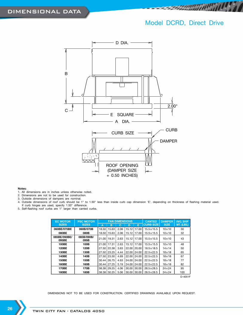
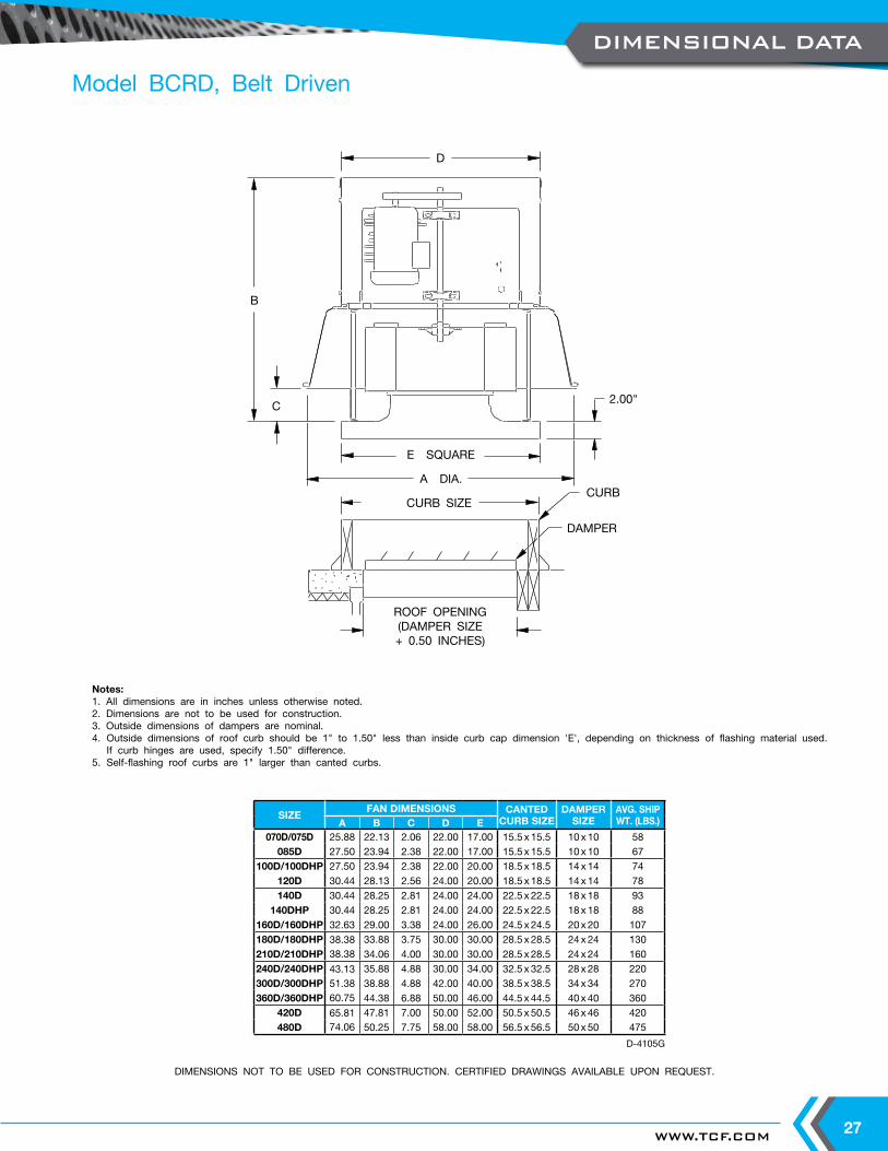
DIMENSIONS NOT TO BE USED FOR CONSTRUCTION. CERTIFIED DRAWINGS AVAILABLE UPON REQUEST.
A DIA.
B
C2.00"
E SQUARE
ROOF OPENING(DAMPER SIZE+ 0.50 INCHES)
CURB SIZECURB
DAMPER
D DIA.
EC MOTORSIZES
PSC MOTOR SIZES
FAN DIMENSIONS CANTEDCURB SIZE
DAMPERSIZE
AVG. SHIP WT. (LBS.)A B C D E
060BE/070BE 060B/070B 18.50 15.63 2.06 15.12 17.00 15.5 x 15.5 10 x 10 30080BE 080B 18.50 15.63 2.06 15.12 17.00 15.5 x 15.5 10 x 10 32
085BE/090BE/095BE
085B/090B/095B 21.00 19.31 2.63 15.12 17.00 15.5 x 15.5 10 x 10 43
100BE 100B 21.00 17.31 2.63 15.12 17.00 15.5 x 15.5 10 x 10 48120BE 120B 27.50 22.38 3.63 22.00 20.00 18.5 x 18.5 14 x 14 50130BE 130B 27.50 23.25 4.44 22.00 24.00 22.5 x 22.5 18 x 18 65140BE 140B 27.50 23.50 4.69 22.00 24.00 22.5 x 22.5 18 x 18 67150BE 150B 30.44 26.75 4.63 24.00 24.00 22.5 x 22.5 18 x 18 77160BE 160B 30.44 27.25 5.19 24.00 24.00 22.5 x 22.5 18 x 18 82170BE 170B 38.38 29.25 4.06 30.00 30.00 28.5 x 28.5 24 x 24 95180BE 180B 38.38 30.25 5.06 30.00 30.00 28.5 x 28.5 24 x 24 100
D-4051F
Notes:1. All dimensions are in inches unless otherwise noted.2. Dimensions are not to be used for construction.3. Outside dimensions of dampers are nominal.4. Outside dimensions of roof curb should be 1" to 1.50" less than inside curb cap dimension 'E', depending on thickness of flashing material used.
If curb hinges are used, specify 1.50" difference.5. Self-flashing roof curbs are 1" larger than canted curbs.
Model DCRD, Direct Drive
DIMENSIONAL DATA
WWW.TCF.COM 27
Model BCRD, Belt Driven
DIMENSIONS NOT TO BE USED FOR CONSTRUCTION. CERTIFIED DRAWINGS AVAILABLE UPON REQUEST.
CURB SIZECURB
DAMPER
2.00"
B
E SQUARE
A DIA.
D
C
ROOF OPENING(DAMPER SIZE+ 0.50 INCHES)
SIZEFAN DIMENSIONS CANTED
CURB SIZEDAMPER
SIZEAVG. SHIP WT. (LBS.)A B C D E
070D/075D 25.88 22.13 2.06 22.00 17.00 15.5 x 15.5 10 x 10 58085D 27.50 23.94 2.38 22.00 17.00 15.5 x 15.5 10 x 10 67
100D/100DHP 27.50 23.94 2.38 22.00 20.00 18.5 x 18.5 14 x 14 74120D 30.44 28.13 2.56 24.00 20.00 18.5 x 18.5 14 x 14 78140D 30.44 28.25 2.81 24.00 24.00 22.5 x 22.5 18 x 18 93
140DHP 30.44 28.25 2.81 24.00 24.00 22.5 x 22.5 18 x 18 88160D/160DHP 32.63 29.00 3.38 24.00 26.00 24.5 x 24.5 20 x 20 107180D/180DHP 38.38 33.88 3.75 30.00 30.00 28.5 x 28.5 24 x 24 130210D/210DHP 38.38 34.06 4.00 30.00 30.00 28.5 x 28.5 24 x 24 160240D/240DHP 43.13 35.88 4.88 30.00 34.00 32.5 x 32.5 28 x 28 220300D/300DHP 51.38 38.88 4.88 42.00 40.00 38.5 x 38.5 34 x 34 270360D/360DHP 60.75 44.38 6.88 50.00 46.00 44.5 x 44.5 40 x 40 360
420D 65.81 47.81 7.00 50.00 52.00 50.5 x 50.5 46 x 46 420480D 74.06 50.25 7.75 58.00 58.00 56.5 x 56.5 50 x 50 475
D-4105G
Notes:1. All dimensions are in inches unless otherwise noted.2. Dimensions are not to be used for construction.3. Outside dimensions of dampers are nominal.4. Outside dimensions of roof curb should be 1" to 1.50" less than inside curb cap dimension 'E', depending on thickness of flashing material used.
If curb hinges are used, specify 1.50" difference.5. Self-flashing roof curbs are 1" larger than canted curbs.
DIMENSIONAL DATA
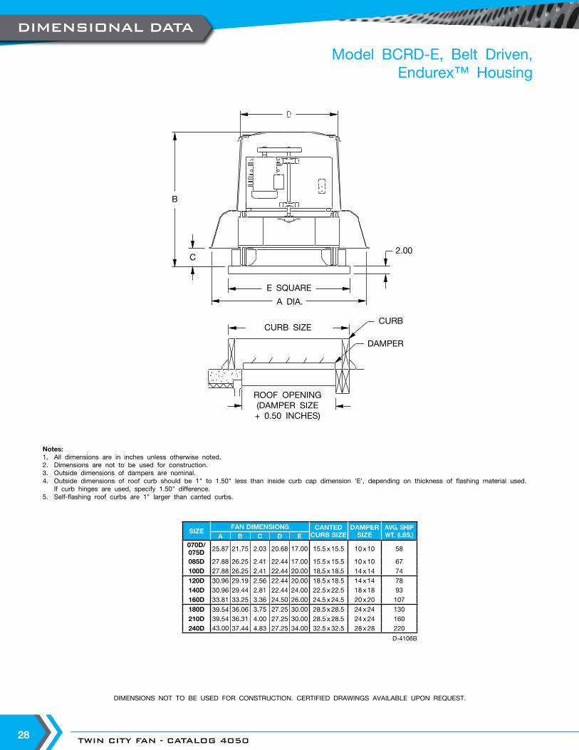
TWIN CITY FAN - CATALOG 405028
Model BCRD-E, Belt Driven,Endurex™ Housing
DIMENSIONS NOT TO BE USED FOR CONSTRUCTION. CERTIFIED DRAWINGS AVAILABLE UPON REQUEST.
Notes:1. All dimensions are in inches unless otherwise noted.2. Dimensions are not to be used for construction.3. Outside dimensions of dampers are nominal.4. Outside dimensions of roof curb should be 1" to 1.50" less than inside curb cap dimension 'E', depending on thickness of flashing material used.
If curb hinges are used, specify 1.50" difference.5. Self-flashing roof curbs are 1" larger than canted curbs.
SIZEFAN DIMENSIONS CANTED
CURB SIZEDAMPER
SIZEAVG. SHIP WT. (LBS.)A B C D E
070D/075D 25.87 21.75 2.03 20.68 17.00 15.5 x 15.5 10 x 10 58
085D 27.88 26.25 2.41 22.44 17.00 15.5 x 15.5 10 x 10 67100D 27.88 26.25 2.41 22.44 20.00 18.5 x 18.5 14 x 14 74
120D 30.96 29.19 2.56 22.44 20.00 18.5 x 18.5 14 x 14 78140D 30.96 29.44 2.81 22.44 24.00 22.5 x 22.5 18 x 18 93160D 33.81 33.25 3.36 24.50 26.00 24.5 x 24.5 20 x 20 107
180D 39.54 36.06 3.75 27.25 30.00 28.5 x 28.5 24 x 24 130210D 39.54 36.31 4.00 27.25 30.00 28.5 x 28.5 24 x 24 160240D 43.00 37.44 4.83 27.25 34.00 32.5 x 32.5 28 x 28 220
D-4106B
2.00
B
E SQUARE
C
A DIA.
ROOF OPENING(DAMPER SIZE+ 0.50 INCHES)
CURB SIZECURB
DAMPER
DIMENSIONAL DATA
WWW.TCF.COM 29
Roof exhaust fans shall be of the direct drive centrifugal type, Model DCRD, as manufactured by Twin City Fan & Blower, Minneapolis, Minnesota.
PERFORMANCE — Fans shall be tested in accordance with AMCA 210 and AMCA 300 test codes for air moving devices and shall be guaranteed by the manufacturer to deliver rated published performance levels. Fans shall be licensed to bear the AMCA certified ratings seal for both sound and air. Models shall be CULUS 705 listed.
CONSTRUCTION — Model DCRD fan housings shall be constructed of aluminum for durability and appearance. Fan spinnings shall have a rolled bead edge for rigidity. Units shall have a deep venturi inlet to prevent snow and rain entry into the building. The curb cap shall include prepunched mounting holes for ease of installation. A conduit chase constructed of electrical metallic tubing shall be provided to the motor compartment. The curb base shall provide protection from weather. Fans shall bear a permanently attached nameplate displaying model and serial number of the unit for future identification.
MOTOR ASSEMBLY — Motor assembly shall be mounted on vibration isolators to eliminate vibration and noise transmission into the ductwork. Motors shall be mounted out of the exhaust airstream.
WHEEL — Fan wheels shall be of the centrifugal backward inclined type, containing a matching inlet venturi for optimum unit performance. Wheels shall be statically and dynamically balanced.
MOTOR — Motors shall be heavy-duty ball bearing type, closely matched to the fan load. All single-phase ODP motors shall contain thermal overload protection. All motors shall be UL and /or CSA recognized. Motors for use with speed control shall provide good speed controllability without any objectionable noise.
DISCONNECT SWITCH — A NEMA 1 disconnect switch shall be supplied with wiring leading from the motor to the junction box (ODP and TEFC motors).
ACCESSORIES — When specified, accessories such as backdraft damper, roof curb, curb hinge, retaining chain, security hasp, variable speed controller, NEMA 3R or NEMA 4 disconnect switches, firestat, aluminum bird screen, aluminum insect screen and special coatings shall be provided by Twin City Fan & Blower to maintain one source responsibility.
FACTORY RUN TEST — All fans prior to shipment shall be completely assembled and test run as a unit at operating speed or maximum RPM allowed for the particular construction type. Each wheel shall be statically and dynamically balanced in accordance with ANSI/AMCA 204-96 "Balance Quality and Vibration Levels for Fans" to Fan Application Category BV-3, Balance Quality Grade G6.3. Balance readings shall be taken by electronic type equipment in the axial, vertical, and horizontal directions on each of the bearings. Records shall be maintained and a written copy shall be available upon request.
GUARANTEE — The manufacturer shall guarantee the workmanship and materials for its roof and wall mounted centrifugal exhaust fans for at least one (1) year from startup or eighteen (18) months from shipment, whichever occurs first.
Twin City Fan
Twin City Fan
ModelDCRD
TYPICAL SPECIFICATIONS
TWIN CITY FAN - CATALOG 405030
Roof mounted exhaust fans shall be of the belt driven centrifugal type, Model BCRD (Spun Aluminum Housing) and as manufactured by Twin City Fan & Blower, Minneapolis, Minnesota.
PERFORMANCE — Fans shall be tested in accordance with AMCA 210 and AMCA 300 test codes for air moving devices and shall be guaranteed by the manufacturer to deliver rated published performance levels. Fans shall be licensed to bear the AMCA certified ratings seal for both sound and air. Models shall be CULUS 705 listed.
CONSTRUCTION — Model BCRD fan housings shall be constructed of spun aluminum and shall offer finish durability and aesthetic appearance. Fan spinnings shall have a rolled bead edge for rigidity. All units have a deep venturi inlet to prevent snow and rain entry into the building. The curb cap shall include prepunched mounting holes for ease of installation. A conduit chase constructed of electrical metallic tubing shall be provided to the motor compartment. The curb base shall provide protection from weather. Lifting lugs shall be provided inside the motor compartment for ease of handling and installation. Fans shall bear a permanently attached nameplate displaying model and serial number of the unit for future identification.
MOTOR AND DRIVE ASSEMBLY — Motor and drive assembly shall be mounted on vibration isolators to eliminate vibration and noise transmission into the ductwork. Motors and drives shall be mounted out of the exhaust airstream.
WHEEL — Fan wheels shall be of the centrifugal backward inclined type, containing a matching inlet venturi for optimum unit performance. Wheels shall be statically and dynamically balanced.
SHAFT — Fan shafts shall be precision-ground and polished. Shafts shall have a first critical speed of at least 125% of the fan’s maximum operating speed.
BEARINGS — Bearings shall be of the one-piece, pillow block type with relubricable zerk fittings. Bearings shall be designed for air handling service with a minimum L-10 life in excess of 100,000 hours; L-50 500,000 hours at the maximum cataloged operating speed. Bearing mounting plate shall have self-aligning tabs for exact locating and alignment of bearings.
DRIVE — Drive assembly shall be constructed of heavy-gauge galvanized steel. Drives shall be sized for a minimum of 150% of driven horsepower. Machined, cast iron motor sheaves shall be adjustable for final system balance.
MOTOR — Motors shall be heavy-duty ball bearing type, closely matched to the fan load. All single-phase ODP motors shall contain thermal overload protection. All motors shall be UL and /or CSA recognized. Motor adjustment shall allow precise belt tensioning for optimum belt life and one-person adjustment and servicing.
DISCONNECT SWITCH — A NEMA 1 disconnect switch shall be supplied with wiring leading from the motor to the junction box (ODP and TEFC motors).
ACCESSORIES — When specified, accessories such as backdraft damper, roof curb, curb hinge, retaining chain, security hasp, NEMA 3R or NEMA 4 disconnect switches, 2-speed switch, firestat, aluminum bird screen, aluminum insect screen and special coatings shall be provided by Twin City Fan & Blower to maintain one source responsibility.
FACTORY RUN TEST — All fans prior to shipment shall be completely assembled and test run as a unit at operating speed or maximum RPM allowed for the particular construction type. Each wheel shall be statically and dynamically balanced in accordance with ANSI/AMCA 204-96 "Balance Quality and Vibration Levels for Fans" to Fan Application Category BV-3, Balance Quality Grade G6.3. Balance readings shall be taken by electronic type equipment in the axial, vertical, and horizontal directions on each of the bearings. Records shall be maintained and a written copy shall be available upon request.
GUARANTEE — The manufacturer shall guarantee the workmanship and materials for its roof and wall mounted centrifugal exhaust fans for at least one (1) year from startup or eighteen (18) months from shipment, whichever occurs first.
ModelBCRD
TYPICAL SPECIFICATIONS
WWW.TCF.COM 31
Roof mounted exhaust fans shall be of the belt driven centrifugal type, Model BCRD-E (Endurex™ Polymeric Housing), as manufactured by Twin City Fan & Blower, Minneapolis, Minnesota.
PERFORMANCE — Fans shall be tested in accordance with AMCA 210 and AMCA 300 test codes for air moving devices and shall be guaranteed by the manufacturer to deliver rated published performance levels. Fans shall be licensed to bear the AMCA certified ratings seal for both sound and air. Models shall be CULUS 705 listed.
CONSTRUCTION — Model BCRD-E fan housings shall be constructed of Endurex™ for impact, weather, corrosion and UV resistance. All units have a deep venturi inlet to prevent snow and rain entry into the building. The curb cap shall include prepunched mounting holes for ease of installation. A conduit chase constructed of electrical metallic tubing shall be provided to the motor compartment. The curb base shall provide protection from weather. Lifting lugs shall be provided inside the motor compartment for ease of handling and installation. Fans shall bear a permanently attached nameplate displaying model and serial number of the unit for future identification.
MOTOR AND DRIVE ASSEMBLY — Motor and drive assembly shall be mounted on vibration isolators to eliminate vibration and noise transmission into the ductwork. Motors and drives shall be mounted out of the exhaust airstream.
WHEEL — Fan wheels shall be of the centrifugal backward inclined type, containing a matching inlet venturi for optimum unit performance. Wheels shall be statically and dynamically balanced.
SHAFT — Fan shafts shall be precision-ground and polished. Shafts shall have a first critical speed of at least 125% of the fan’s maximum operating speed.
BEARINGS — Bearings shall be of the one-piece, pillow block type with relubricable zerk fittings. Bearings shall be designed for air handling service with a minimum L-10 life in excess of 100,000 hours; L-50 500,000 hours at the maximum cataloged operating speed. Bearing mounting plate shall have self-aligning tabs for exact locating and alignment of bearings.
DRIVE — Drive assembly shall be constructed of heavy-gauge galvanized steel. Drives shall be sized for a minimum of 150% of driven horsepower. Machined, cast iron motor sheaves shall be adjustable for final system balance.
MOTOR — Motors shall be heavy-duty ball bearing type, closely matched to the fan load. All single-phase ODP motors shall contain thermal overload protection. All motors shall be UL and /or CSA recognized. Motor adjustment shall allow precise belt tensioning for optimum belt life and one-person adjustment and servicing.
DISCONNECT SWITCH — A NEMA 1 disconnect switch shall be supplied with wiring leading from the motor to the junction box (ODP and TEFC motors).
ACCESSORIES — When specified, accessories such as backdraft damper, roof curb, curb hinge, retaining chain, security hasp, NEMA 3R or NEMA 4 disconnect switches, 2-speed switch, firestat, aluminum bird screen, aluminum insect screen and special coatings shall be provided by Twin City Fan & Blower to maintain one source responsibility.
FACTORY RUN TEST — All fans prior to shipment shall be completely assembled and test run as a unit at operating speed or maximum RPM allowed for the particular construction type. Each wheel shall be statically and dynamically balanced in accordance with ANSI/AMCA 204-96 "Balance Quality and Vibration Levels for Fans" to Fan Application Category BV-3, Balance Quality Grade G6.3. Balance readings shall be taken by electronic type equipment in the axial, vertical, and horizontal directions on each of the bearings. Records shall be maintained and a written copy shall be available upon request.
GUARANTEE — The manufacturer shall guarantee the workmanship and materials for its roof and wall mounted centrifugal exhaust fans for at least one (1) year from startup or eighteen (18) months from shipment, whichever occurs first. All Endurex™ housing components shall have a limited lifetime warranty.
ModelBCRD-E
TYPICAL SPECIFICATIONS
TWIN CITY FAN & BLOWERWWW.TCF.COM
5959 TRENTON LANE N | MINNEAPOLIS, MN 55442 | PHONE: 763-551-7600 | FAX: 763-551-7601
CENTRIFUGAL FANS | UTILITY SETS | PLENUM & PLUG FANS | INLINE CENTRIFUGAL FANS
MIXED FLOW FANS | TUBEAXIAL & VANEAXIAL FANS | PROPELLER WALL FANS | PROPELLER ROOF VENTILATORS
CENTRIFUGAL ROOF & WALL EXHAUSTERS | CEILING VENTILATORS | GRAVITY VENTILATORS | DUCT BLOWERS
RADIAL BLADED FANS | RADIAL TIP FANS | HIGH EFFICIENCY INDUSTRIAL FANS | PRESSURE BLOWERS
LABORATORY EXHAUST FANS | FILTERED SUPPLY FANS | MANCOOLERS | FIBERGLASS FANS | CUSTOM FANS
INDUSTRIAL PROCESS ANDCOMMERCIAL VENTILATION SYSTEMS
©2018 Twin City Fan Companies, Ltd., Minneapolis, MN. All rights reserved. Catalog illustrations cover the general appearance of Twin City
Fan & Blower products at the time of publication and we reserve the right to make changes in design and construction at any time without notice.
Twin City Fan
Twin City Fan