Embed Size (px)
Citation preview
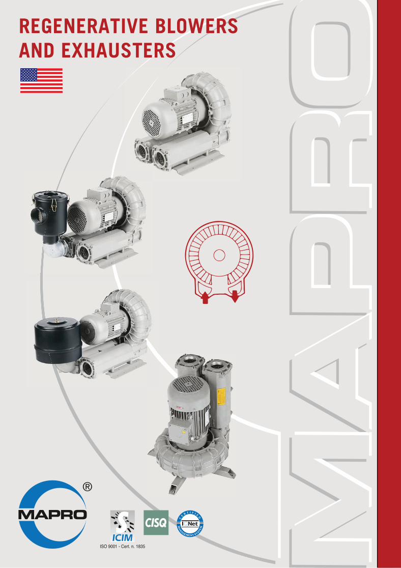
REGENERATIVE BLOWERSAND EXHAUSTERS
2
MAP
RO
REGENERATIVE MACHINES
Range of duty
280
240
200
160
120
80
40
100 200 300 400 005 006 007 008 009
200
160
120
80
40
100 200 300 400 005 006 007 008 009Flow rate [CFM] Flow rate[CFM]
Outle
t pre
ssur
e [in
H2O]
Inle
t vac
uum
[inH
2O]
Blowers Exhausters
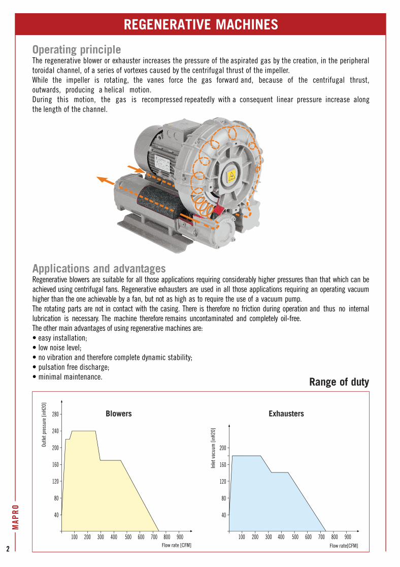
Operating principleThe regenerative blower or exhauster increases the pressure of the aspirated gas by the creation, in the peripheral toroidal channel, of a series of vortexes caused by the centrifugal thrust of the impeller. While the impeller is rotating, the vanes force the gas forward and, because of the centrifugal thrust, outwards, producing a helical motion.During this motion, the gas is recompressed repeatedly with a consequent linear pressure increase along the length of the channel.
Applications and advantagesRegenerative blowers are suitable for all those applications requiring considerably higher pressures than that which can be achieved using centrifugal fans. Regenerative exhausters are used in all those applications requiring an operating vacuum higher than the one achievable by a fan, but not as high as to require the use of a vacuum pump.The rotating parts are not in contact with the casing. There is therefore no friction during operation and thus no internal lubrication is necessary. The machine therefore remains uncontaminated and completely oil-free.The other main advantages of using regenerative machines are:• easy installation;• low noise level;• no vibration and therefore complete dynamic stability;• pulsation free discharge; • minimal maintenance.
MAP
RO
3
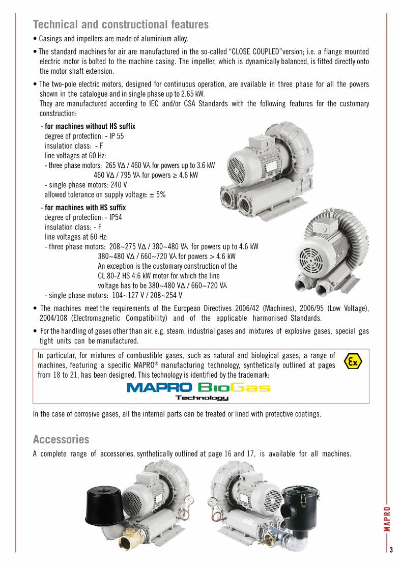
Technical and constructional features• Casings and impellers are made of aluminium alloy.
• The standard machines for air are manufactured in the so-called “CLOSE COUPLED”version; i.e. a flange mounted electric motor is bolted to the machine casing. The impeller, which is dynamically balanced, is fitted directly onto the motor shaft extension.
• The two-pole electric motors, designed for continuous operation, are available in three phase for all the powers shown in the catalogue and in single phase up to 2.65 kW. They are manufactured according to IEC and/or CSA Standards with the following features for the customary construction:
- for machines without HS suffixdegree of protection: - IP 55insulation class: - Fline voltages at 60 Hz:- three phase motors: 265 VΔ / 460 V for powers up to 3.6 kW 460 VΔ / 795 V for powers ≥ 4.6 kW - single phase motors: 240 Vallowed tolerance on supply voltage: ± 5%
- for machines with HS suffixdegree of protection: - IP54insulation class: - Fline voltages at 60 Hz:- three phase motors: 208~275 VΔ / 380~480 V for powers up to 4.6 kW 380~480 VΔ / 660~720 V for powers > 4.6 kW An exception is the customary construction of the CL 80-Z HS 4.6 kW motor for which the line voltage has to be 380~480 VΔ / 660~720 V- single phase motors: 104~127 V / 208~254 V
• The machines meet the requirements of the European Directives 2006/42 (Machines), 2006/95 (Low Voltage), 2004/108 (Electromagnetic Compatibility) and of the applicable harmonised Standards.
• For the handling of gases other than air, e.g. steam, industrial gases and mixtures of explosive gases, special gas tight units can be manufactured.
In particular, for mixtures of combustible gases, such as natural and biological gases, a range of machines, featuring a specific MAPRO® manufacturing technology, synthetically outlined at pages from 18 to 21, has been designed. This technology is identified by the trademark:
In the case of corrosive gases, all the internal parts can be treated or lined with protective coatings.
AccessoriesA complete range of accessories, synthetically outlined at page 16 and 17, is available for all machines.
MAPRO
4
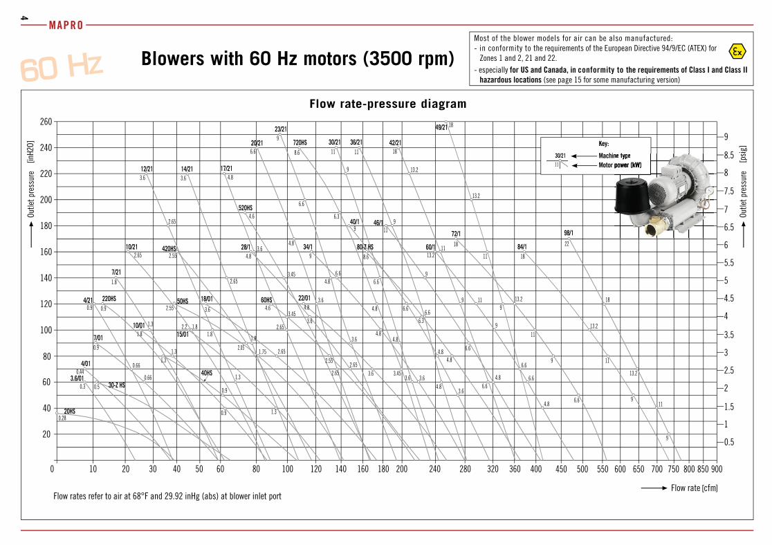
Blowers with 60 Hz motors (3500 rpm)
1.3
9
8.6
6.3
18
0.3 0.5
0,44
0.9
3.6 4.60.9 0.9
1.8
3.6
4.8
4.6
0.28
2.65
3.6
4.82.65 2.55
3.6
2.65
0.66
0.9
1.3
1.8
0.9
1.3
2.2
1.752.05
2.55
2.65
3.454.8
6.6
9
0.66
1.3 2.65
3.6
4.8
3.454.8
1.8
3.6
1.8
1.3
1.8
2.55
3.63.6
3.45
4.8
4.8
6.64.8
9
8.6
9
11
13.2
2.65
6.6
6.6
3.6
3.6
4.8
6.6
9
11 11
9
6.66.3
4.8
13.2
18
2.65
3.6
4.8
6.6
6.6
9
11
6.6
9
11
13.2
18
9
11
13.2
18
22
6.6
9
11
13.2
9
11
13.2
18
6.6
9
11
4.8
4.8
3.6/0130-Z HS
4/01
7/01
10/01
40HS
15/01
50HS 18/01 60HS 22/01
34/1
40/1 46/1
80-Z HS 60/1
72/1 98/1
4/21 220HS
7/21
17/21
20/21
23/21
720HS 30/21 36/21
49/21
20HS
84/1
42/21
14/21
28/110/21
12/21
520HS
420HS
20
40
100
120
140
160
180
200
220
240
260
10 60 100 400 45020 40 80 120 1800
0.5
1.5
2
2.5
3
3.5
4
4.5
5
5.5
6
6.5
7
[inH2
O]
[cfm]
30 50 140 160
60
80
200 240 280 320 360 500 550 600 900650 700
[psig
]
1
7.5
8
8.5
9
Flow rate-pressure diagram
Flow rates refer to air at 68°F and 29.92 inHg (abs) at blower inlet portFlow rate
Outle
t pre
ssur
e
Key:
Machine type Motor power (kW)
30/2111
750 800 850
Outle
t pre
ssur
e
Most of the blower models for air can be also manufactured:- in conformity to the requirements of the European Directive 94/9/EC (ATEX) for
Zones 1 and 2, 21 and 22.- especially for US and Canada, in conformity to the requirements of Class I and Class II
hazardous locations (see page 15 for some manufacturing version)
nene ttypypeepopowweerr ((kWkW))
5
MAP
RO®
Outlet pressure
Flow rate cfmMotor power kW kW kW kW kW kW kW kW kW kW kW kW kW kW kW kW kW kW kW kW kW kW kW kW kW
BlowerType
CL 20 HS 38.8 0.28 14.1 0.28 [ 0 CFM at 36 inH2O]
CL 30-Z HS 63 0.5 37 0.5 28.2 0.5 19.4 0.5 10.5 0.5
CL 3.6/01 23.5 0.3 15 0.3 12 0.3 9.7 0.3 7 0.3
CL 4/01 36.4 0.44 24.1 0.44 20 0.44 15.8 0.44 11.7 0.44 7 0.44
CL 7/01 58.8 0.66 42.3 0.66 37 0.66 31.7 0.66 26.4 0.66 21.1 0.9 15.8 0.9 10.5 0.9
CL 10/01 85 0.9 67 0.9 61 0.9 55.3 1.3 49.4 1.3 43.5 1.3 37.6 1.3 31.7 1.8 25.3 1.8
CL 40 HS 103 1.15 (•) 77 1.15 (•) 68 1.15 (•) 60 1.15 (•) 51.7 1.5 (•) 43.5 1.5 (•) 34.7 1.5 (•)
CL 15/01 122 1.3 98 1.3 91 1.3 83 2.2 75 2.2 67 2.2 60 2.2 52.3 2.2 44.7 2.2
CL 50 HS 141 122 1.75(•) 115 1.75(•) 107 1.75(•) 98 1.75(•) 90 1.75(•) 80 1.75(•) 70 2.55 60 2.55 2.55 (+) 48.8 37.6 2.55 (+)
CL 18/01 171 2.65 141 2.65 131 2.65 121 2.65 111 2.65 101 2.65 91 2.65 81 3.6 71 3.6 61 3.6 51.7 3.6
CL 60 HS 211 2.55 181 2.55 170 2.55 160 2.55 150 2.55 140 2.55 130 2.55 120 3.45 109 3.45 98 4.6 88 4.6
CL 28/1 217 2.65 183 2.65 173 2.65 164 2.65 155 2.65 147 2.65 138 3.6 130 3.6 122 3.6 114 3.6 107 4.8 99 4.8 91 4.8 84 4.8 76 4.8
CL 22/01 251 3.6 216 3.6 204 3.6 192 3.6 180 3.6 168 3.6 157 4.8 145 4.8 133 4.8 121 4.8 110 4.8
CL 34/1 277 3.6 247 3.6 237 3.6 227 3.6 217 3.6 206 4.8 196 4.8 186 4.8 176 4.8 166 6.6 156 6.6 146 6.6 136 6.6 126 9 115 9
CL 40/1 317 3.6 288 3.6 278 3.6 269 3.6 260 4.8 250 4.8 241 4.8 231 6.6 222 6.6 213 6.6 203 6.6 194 9 184 9 175 9 165 9 156 9 147 9
CL 80-Z HS (+) 364 4.6 326 4.6 313 4.6 300 4.6 287 4.6 274 4.6 261 6.3 248 6.3 235 6.3 222 8.6 209 8.6 196 8.6 183 8.6 170 8.6 157 8.6
CL 46/1 406 4.8 360 4.8 346 4.8 333 4.8 320 4.8 308 6.6 296 6.6 284 6.6 273 9 261 9 250 9 238 9 227 9 216 11 204 11 193 11 181 11
CL 60/1 476 4.8 424 4.8 409 4.8 395 6.6 381 6.6 367 9 353 9 339 9 324 9 310 11 296 11 282 13.2 268 13.2 254 13.2 240 13.2
CL 72/1 562 6.6 521 6.6 506 6.6 489 6.6 472 9 453 9 434 9 416 11 397 11 378 13.2 359 13.2 340 18 321 18 303 18 284 18 265 18
CL 84/1 735 9 675 9 652 9 629 9 606 11 583 11 560 11 537 13.2 514 13.2 491 18 468 18 445 18 422 18 399 18 376 18
CL 98/1 768 9 716 11 697 11 679 13.2 662 13.2 644 13.2 626 18 609 18 591 18 573 18 556 18 538 22 520 22 503 22 485 22 467 22
CL 4/21 38.2 0.66 31.1 0.66 28.8 0.66 26.4 0.66 24.1 0.66 21.7 0.66 19.4 0.9 17 0.9 14.7 0.9 12.3 0.9 10 0.9
CL 7/21 58.8 1.3 50 1.3 47 1.3 44.1 1.3 41.2 1.3 38.2 1.3 34.7 1.3 31.7 1.3 28.8 1.3 25.8 1.8 22.9 1.8 20 1.8 16.4 1.8
CL 220 HS 61 0.9 50 0.9 45.9 0.9 42.3 0.9 38.2 0.9 34.7 0.9 30.6 0.9 26.4 0.9 22.3 0.9(•) 18.2 0.9(•) 12.3 0.9(•)
CL 10/21 85 1.8 74 1.8 70 1.8 65 1.8 61 1.8 57.6 1.8 53.5 1.8 49.4 1.8 45.3 1.8 41.2 2.65 37 2.65 32.9 2.65 28.8 2.65 24.7 2.65 20.6 2.65
CL 12/21 88 1.3 78 1.3 74 1.3 71 1.3 67 1.3 64 1.8 61 1.8 58.2 1.8 55.3 1.8 52.3 2.65 50 2.65 47.6 2.65 45.3 2.65 42.9 2.65 40.6 2.65 38.2 2.65 35.9 2.65 33.5 3.6 31.1 3.6 28.8 3.6 26.4 3.6
CL 420 HS 115 2.05 (•) 101 2.05 (•) 96 2.05 (•) 91 2.05 (•) 87 2.05 (•) 82 2.05 (•) 77 2.05 (•) 72 2.05 (•) 68 2.55 63 2.55 58.8 2.55 54.1 2.55 49.4 2.55 44.7 2.55 40 2.55
CL 14/21 105 1.8 94 1.8 91 1.8 88 1.8 85 1.8 82 1.8 80 1.8 77 1.8 74 2.65 72 2.65 69 2.65 66 2.65 63 2.65 61 3.6 58.2 3.6 55.9 3.6 52.9 3.6 50.6 3.6 48.2 3.6 45.9 3.6 44.1 3.6
CL 17/21 138 2.65 126 2.65 122 2.65 118 2.65 114 2.65 110 2.65 105 2.65 101 2.65 97 2.65 93 3.6 90 3.6 85 3.6 82 3.6 78 3.6 75 3.6 72 4.8 69 4.8 67 4.8 65 4.8 63 4.8 61 4.8
CL 520 HS 165 3.45 150 3.45 145 3.45 140 3.45 135 3.45 130 3.45 125 3.45 120 3.45 115 3.45 110 3.45 105 3.45 100 3.45 95 3.45 90 4.6 85 4.6 80 4.6 75 4.6 70 4.6 ( )
CL 20/21 164 2.65 150 2.65 145 2.65 142 2.65 138 2.65 134 2.65 131 3.6 128 3.6 125 3.6 121 3.6 118 3.6 115 4.8 112 4.8 108 4.8 105 4.8 102 4.8 99 6.6 95 6.6 92 6.6 89 6.6 86 6.6 82 6.6 80 6.6
CL 23/21 192 3.6 177 3.6 172 3.6 167 3.6 162 3.6 157 3.6 153 3.6 148 3.6 144 4.8 141 4.8 137 4.8 134 4.8 131 4.8 127 6.6 124 6.6 121 6.6 117 6.6 114 6.6 110 6.6 107 9 103 9 100 9 96 9 160 9
CL 720 HS (+) 231 3.45 217 3.45 211 3.45 207 3.45 201 3.45 197 3.45 192 4.8 187 4.8 182 4.8 177 4.8 172 4.8 167 6.3 162 6.3 157 6.3 152 6.3 147 6.3 142 6.3 137 6.3 132 8.6 127 8.6 120 8.6 113 8.6 104 8.6
CL 30/21 243 3.6 225 3.6 219 3.6 214 3.6 209 3.6 204 4.8 200 4.8 195 4.8 191 6.6 187 6.6 183 6.6 179 6.6 175 6.6 171 9 167 9 163 9 158 9 154 9 150 9 146 9 142 9 138 11 134 11
CL 36/21 280 4.8 264 4.8 258 4.8 253 4.8 248 4.8 243 6.6 237 6.6 232 6.6 227 6.6 221 6.6 216 9 211 9 206 9 201 9 196 9 191 9 186 9 181 11 176 11 171 11 165 11 160 11 155 11
CL 42/21 359 6.6 336 6.6 329 6.6 322 6.6 315 6.6 308 6.6 301 9 294 9 287 9 280 9 273 9 266 11 259 11 252 11 246 11 239 13.2 233 13.2 226 13.2 220 13.2 213 13.2 207 13.2 200 18 194 18
CL 49/21 412 6.6 392 6.6 386 6.6 380 6.6 374 6.6 367 6.6 361 9 355 9 349 9 343 9 337 9 330 11 324 11 318 11 312 11 306 13.2 300 13.2 294 13.2 288 13.2 282 18 276 18 270 18 264 18 258 18 253 18
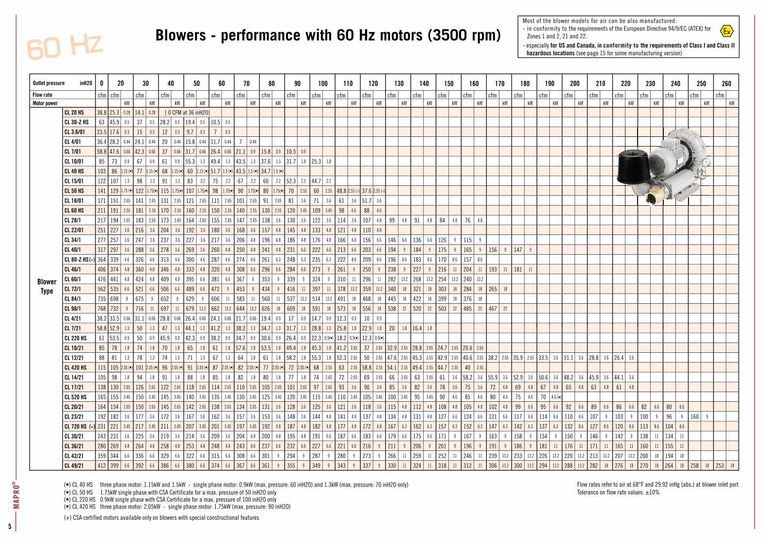
Flow rates refer to air at 68°F and 29.92 inHg (abs.) at blower inlet portTolerance on flow rate values: ±10%
(•) CL 40 HS three phase motor: 1.15kW and 1.5kW - single phase motor: 0.9kW (max. pressure: 60 inH2O) and 1.3kW (max. pressure: 70 inH2O only)(•) CL 50 HS 1.75kW single phase with CSA Certificate for a max. pressure of 50 inH2O only
Blowers - performance with 60 Hz motors (3500 rpm)
inH2O
cfm cfm cfm cfm cfm cfm cfm cfm cfm cfm cfm cfm cfm cfm cfm cfm cfm cfm cfm cfm cfm cfm cfm cfm cfm
0 20 30
25.3
45.9
17.6
28.2
47.6
73
86
107
129
151
191
194
227
257
297
339
374
441
535
698
732
33.5
52.9
53.5
78
81
105
98
130
155
154
182
221
231
269
344
399
40 50 60 70 80 90 100 110 120 130 140 150 160 170 180 190 200 210 220 230 240 250 260
1.75 (•)
(•) CL 220 HS 0.9kW single phase with CSA Certificate for a max. pressure of 100 inH2O only(•) CL 420 HS three phase motor: 2.05kW - single phase motor: 1.75kW (max. pressure: 90 inH2O)
(+) CSA certified motors available only on blowers with special constructional features
Most of the blower models for air can be also manufactured:- in conformity to the requirements of the European Directive 94/9/EC (ATEX) for
Zones 1 and 2, 21 and 22.- especially for US and Canada, in conformity to the requirements of Class I and Class II
hazardous locations (see page 15 for some manufacturing version)
7
MAP
RO®
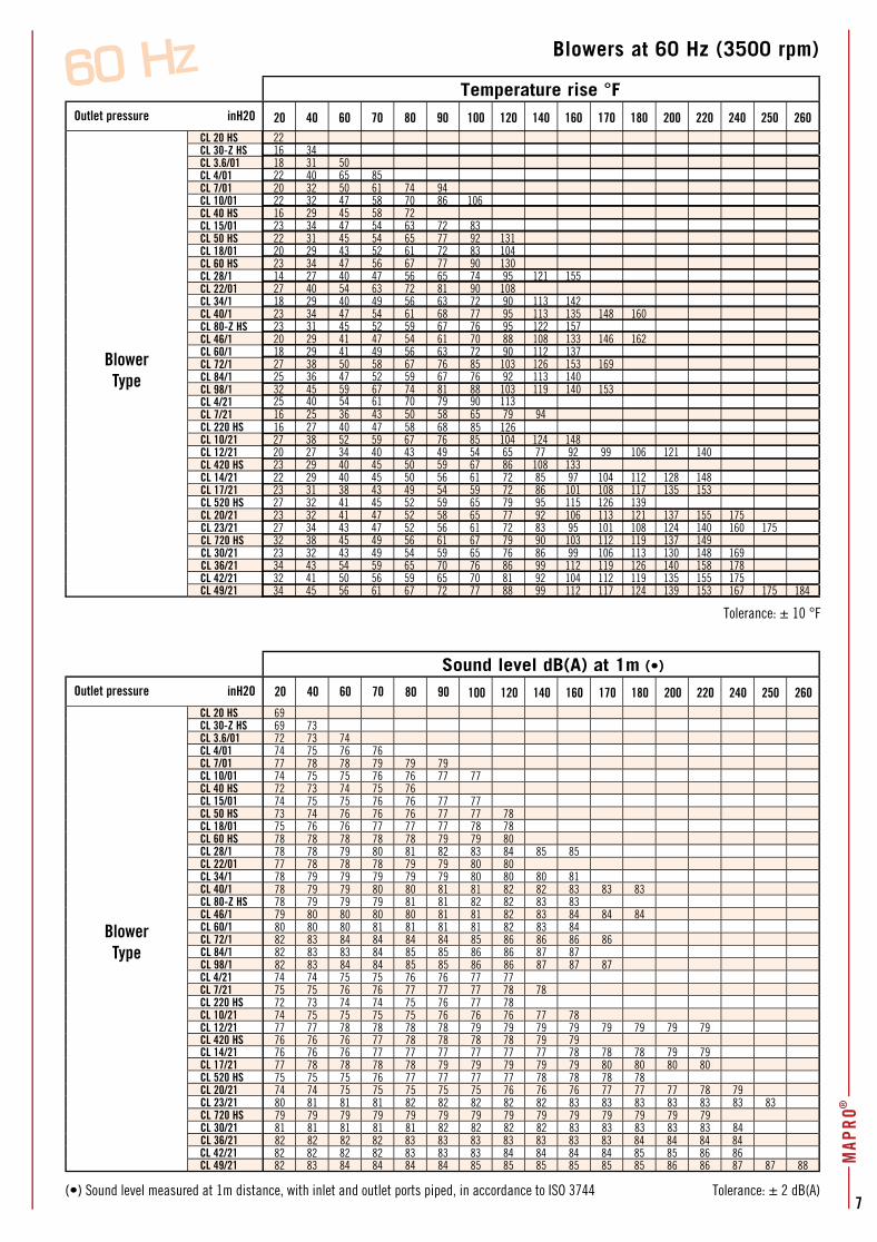
Blowers at 60 Hz (3500 rpm)
Tolerance: ± 10 °F
Tolerance: ± 2 dB(A)
Temperature rise °FOutlet pressure inH2O 20
BlowerType
CL 20 HSCL 30-Z HSCL 3.6/01CL 4/01 CL 7/01CL 10/01CL 40 HS CL 15/01CL 50 HSCL 18/01CL 60 HSCL 28/1CL 22/01CL 34/1CL 40/1CL 80-Z HSCL 46/1CL 60/1CL 72/1CL 84/1CL 98/1CL 4/21CL 7/21CL 220 HSCL 10/21CL 12/21CL 420 HSCL 14/21CL 17/21CL 520 HSCL 20/21CL 23/21CL 720 HSCL 30/21CL 36/21CL 42/21CL 49/21
Sound level dB(A) at 1m (•)
Outlet pressure inH2O
BlowerType
CL 20 HS 69CL 30-Z HS 69 73CL 3.6/01 72 73 74CL 4/01 74 75 76 76CL 7/01 77 78 78 79 79 79CL 10/01 74 75 75 76 76 77 77CL 40 HS 72 73 74 75 76CL 15/01 74 75 75 76 76 77 77CL 50 HS 73 74 76 76 76 77 77 78CL 18/01 75 76 76 77 77 77 78 78CL 60 HS 78 78 78 78 78 79 79 80CL 28/1 78 78 79 80 81 82 83 84 85 85CL 22/01 77 78 78 78 79 79 80 80CL 34/1 78 79 79 79 79 79 80 80 80 81CL 40/1 78 79 79 80 80 81 81 82 82 83 83 83CL 80-Z HS 78 79 79 79 81 81 82 82 83 83CL 46/1 79 80 80 80 80 81 81 82 83 84 84 84CL 60/1 80 80 80 81 81 81 81 82 83 84CL 72/1 82 83 84 84 84 84 85 86 86 86 86CL 84/1 82 83 83 84 85 85 86 86 87 87CL 98/1 82 83 84 84 85 85 86 86 87 87 87CL 4/21 74 74 75 75 76 76 77 77CL 7/21 75 75 76 76 77 77 77 78 78CL 220 HS 72 73 74 74 75 76 77 78CL 10/21 74 75 75 75 75 76 76 76 77 78CL 12/21 77 77 78 78 78 78 79 79 79 79 79 79 79 79CL 420 HS 76 76 76 77 78 78 78 78 79 79CL 14/21 76 76 76 77 77 77 77 77 77 78 78 78 79 79CL 17/21 77 78 78 78 78 79 79 79 79 79 80 80 80 80CL 520 HS 75 75 75 76 77 77 77 77 78 78 78 78CL 20/21 74 74 75 75 75 75 75 76 76 76 77 77 77 78 79CL 23/21 80 81 81 81 82 82 82 82 82 83 83 83 83 83 83 83CL 720 HS 79 79 79 79 79 79 79 79 79 79 79 79 79 79CL 30/21 81 81 81 81 81 82 82 82 82 83 83 83 83 83 84CL 36/21 82 82 82 82 83 83 83 83 83 83 83 84 84 84 84CL 42/21 82 82 82 82 83 83 83 84 84 84 84 85 85 86 86CL 49/21 82 83 84 84 84 84 85 85 85 85 85 85 86 86 87 87 88
2216 3418 31 5022 40 65 8520 32 50 61 74 9422 32 47 58 70 86 10616 29 45 58 7223 34 47 54 63 72 8322 31 45 54 65 77 92 13120 29 43 52 61 72 83 10423 34 47 56 67 77 90 13014 27 40 47 56 65 74 95 121 15527 40 54 63 72 81 90 10818 29 40 49 56 63 72 90 113 14223 34 47 54 61 68 77 95 113 135 148 16023 31 45 52 59 67 76 95 122 15720 29 41 47 54 61 70 88 108 133 146 16218 29 41 49 56 63 72 90 112 13727 38 50 58 67 76 85 103 126 153 16925 36 47 52 59 67 76 92 113 14032 45 59 67 74 81 88 103 119 140 15325 40 54 61 70 79 90 11316 25 36 43 50 58 65 79 9416 27 40 47 58 68 85 12627 38 52 59 67 76 85 104 124 14820 27 34 40 43 49 54 65 77 92 99 106 121 14023 29 40 45 50 59 67 86 108 13322 29 40 45 50 56 61 72 85 97 104 112 128 14823 31 38 43 49 54 59 72 86 101 108 117 135 15327 32 41 45 52 59 65 79 95 115 126 13923 32 41 47 52 58 65 77 92 106 113 121 137 155 17527 34 43 47 52 56 61 72 83 95 101 108 124 140 160 17532 38 45 49 56 61 67 79 90 103 112 119 137 14923 32 43 49 54 59 65 76 86 99 106 113 130 148 16934 43 54 59 65 70 76 86 99 112 119 126 140 158 17832 41 50 56 59 65 70 81 92 104 112 119 135 155 17534 45 56 61 67 72 77 88 99 112 117 124 139 153 167 175 184
40 60 70 80 90 100 120 140 160 170 180 200 220 240 250 260
(•) Sound level measured at 1m distance, with inlet and outlet ports piped, in accordance to ISO 3744
20 40 60 70 80 90 100 120 140 160 170 180 200 220 240 250 260
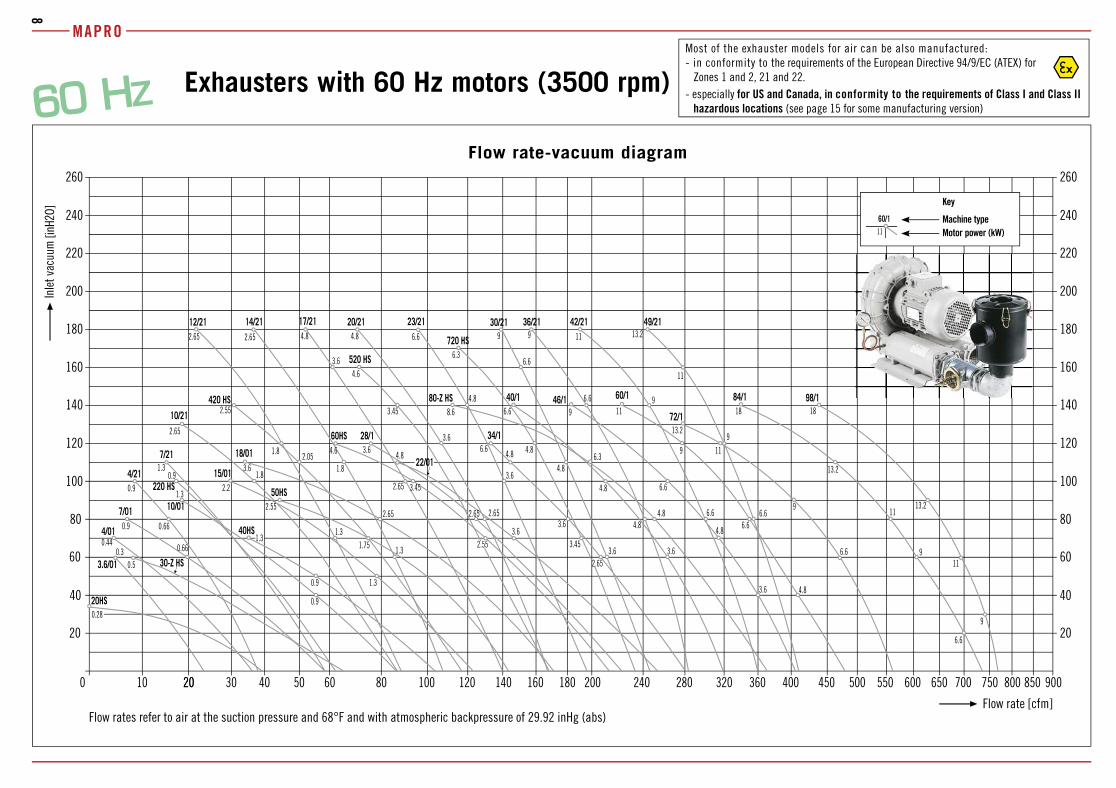
Exhausters with 60 Hz motors (3500 rpm)
MAPRO
8
2.55
2.553.6
3.45
4.8 4.86.6
6.6 9 11
3.6
3.6
4.8
8.6
6.6
6.3
4.8
6.6
9
6.6
9 13.211
2.65
4.8
6.3
3.6
6.6
4.8
6.6
6.6
9
9
11
13.2
9
11
13.2
18
4.8 6.6
9
11
6.6
9
11
13.2
18
6.6
4.8
9
0.9
3.63.6
2.65
0.30.5
0.440.66
0.9
0.9
1.3
1.31.75
2.65
3.6
3.45
4.6 4.8
0.66
0.9
1.30.9
0.28
2.65
3.6
4.8 4.8
4.6
3.45
2.2
1.3
3.6
2.65
2.55
2.05
1.8
1.8
1.3
2.65
1.8
1.3
2.653.6
2.65
4.8
3.6/01 30-Z HS
4/01
7/01 10/01
220 HS
40HS
15/01
50HS
18/01
60HS
22/01
34/1
46/1 60/1
72/1
98/1
17/21 20/21 23/21 30/21 36/21 49/21
4/21
7/21
20HS
84/1
42/21
10/21
12/21 14/21
28/1
720 HS
80-Z HS
520 HS
420 HS 40/1
10 12020 50 80 160 600 9000
[inH2
O]
3020 40 60 100 140 180 200 240
60/111
Flow rate-vacuum diagram
Flow rates refer to air at the suction pressure and 68°F and with atmospheric backpressure of 29.92 inHg (abs)Flow rate [cfm]
Key
Machine type Motor power (kW)
Inle
t vac
uum
280 320 360 400 450 500 550 650 700 750 850800
Most of the exhauster models for air can be also manufactured:- in conformity to the requirements of the European Directive 94/9/EC (ATEX) for
Zones 1 and 2, 21 and 22.- especially for US and Canada, in conformity to the requirements of Class I and Class II
hazardous locations (see page 15 for some manufacturing version)
20
40
100
120
140
160
180
200
220
240
260
60
80
20
40
100
120
140
160
180
200
220
240
260
60
80
9
MAP
RO
Inlet vacuum
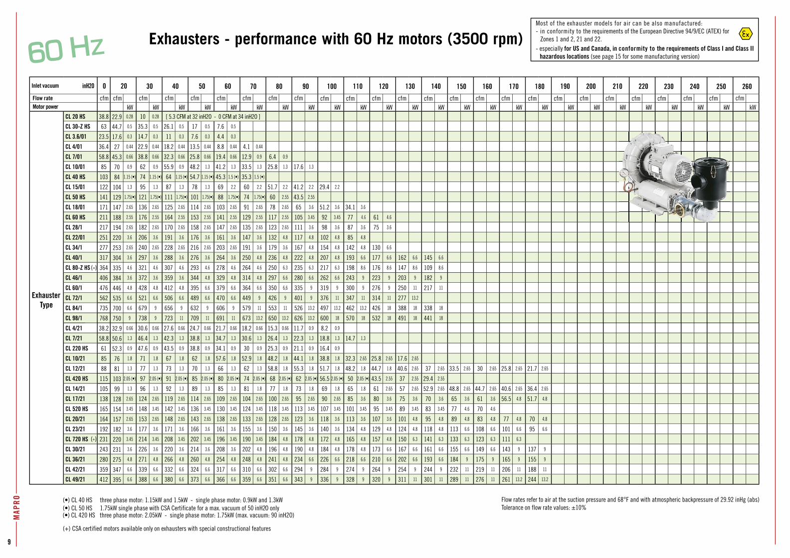
Flow rateMotor power kW kW kW kW kW kW kW kW kW kW kW kW kW kW kW kW kW kW kW kW kW kW kW kW kW
CL 20 HS 0.28 10 0.28 [ 5.3 CFM at 32 inH2O - 0 CFM at 34 inH2O ]
CL 30-Z HS 0.5 35.3 0.5 26.1 0.5 17 0.5 7.6 0.5
CL 3.6/01 0.3 14.7 0.3 11 0.3 7.6 0.3 4.4 0.3
CL 4/01 0.44 22.9 0.44 18.2 0.44 13.5 0.44 8.8 0.44 4.1 0.44
CL 7/01 0.66 38.8 0.66 32.3 0.66 25.8 0.66 19.4 0.66 12.9 0.9 6.4 0.9
CL 10/01 0.9 62 0.9 55.9 0.9 48.2 1.3 41.2 1.3 33.5 1.3 25.8 1.3 17.6 1.3
CL 40 HS 1.15 (•) 74 1.15 (•) 64 1.15 (•) 54.7 1.15 (•) 45.3 1.5 (•) 35.3 1.5 (•)
CL 15/01 1.3 95 1.3 87 1.3 78 1.3 69 2.2 60 2.2 51.7 2.2 41.2 2.2 29.4 2.2
CL 50 HS 1.75(•) 121 1.75(•) 111 1.75(•) 101 1.75(•) 88 1.75(•) 74 1.75(•) 60 2.55 43.5 2.55
CL 18/01 2.65 136 2.65 125 2.65 114 2.65 103 2.65 91 2.65 78 2.65 65 3.6 51.2 3.6 34.1 3.6
CL 60 HS 2.55 176 2.55 164 2.55 153 2.55 141 2.55 129 2.55 117 2.55 105 3.45 92 3.45 77 4.6 61 4.6
CL 28/1 2.65 182 2.65 170 2.65 158 2.65 147 2.65 135 2.65 123 2.65 111 3.6 98 3.6 87 3.6 75 3.6
CL 22/01 3.6 206 3.6 191 3.6 176 3.6 161 3.6 147 3.6 132 4.8 117 4.8 102 4.8 85 4.8
CL 34/1 2.65 240 2.65 228 2.65 216 2.65 203 2.65 191 3.6 179 3.6 167 4.8 154 4.8 142 4.8 130 6.6
CL 40/1 3.6 297 3.6 288 3.6 276 3.6 264 3.6 250 4.8 236 4.8 222 4.8 207 4.8 193 6.6 177 6.6 162 6.6 145 6.6
CL 80-Z HS 4.6 321 4.6 307 4.6 293 4.6 278 4.6 264 4.6 250 6.3 235 6.3 217 6.3 198 8.6 176 8.6 147 8.6 109 8.6
CL 46/1 3.6 372 3.6 359 3.6 344 4.8 329 4.8 314 4.8 297 6.6 280 6.6 262 6.6 243 9 223 9 203 9 182 9
CL 60/1 4.8 428 4.8 412 4.8 395 6.6 379 6.6 364 6.6 350 6,6 335 9 319 9 300 9 276 9 250 11 217 11
CL 72/1 6.6 521 6.6 506 6.6 489 6.6 470 6.6 449 9 426 9 401 9 376 11 347 11 314 11 277 13.2
CL 84/1 6.6 679 9 656 9 632 9 606 9 579 11 553 11 526 13.2 497 13.2 462 13.2 426 18 388 18 338 18
CL 98/1 9 738 9 723 11 709 11 691 11 673 13.2 650 13.2 626 13.2 600 18 570 18 532 18 491 18 441 18
CL 4/21 0.66 30.6 0.66 27.6 0.66 24.7 0.66 21.7 0.66 18.2 0.66 15.3 0.66 11.7 0.9 8.2 0.9
CL 7/21 1.3 46.4 1.3 42.3 1.3 38.8 1.3 34.7 1.3 30.6 1.3 26.4 1.3 22.3 1.3 18.8 1.3 14.7 1.3
CL 220 HS 0.9 47.6 0.9 43.5 0.9 38.8 0.9 34.1 0.9 30 0.9 25.3 0.9 21.1 0.9 16.4 0.9
CL 10/21 1.8 71 1.8 67 1.8 62 1.8 57.6 1.8 52.9 1.8 48.2 1.8 44.1 1.8 38.8 1.8 32.3 2.65 25.8 2.65 17.6 2.65
CL 12/21 1.3 77 1.3 73 1.3 70 1.3 66 1.3 62 1.3 58.8 1.8 55.3 1.8 51.7 1.8 48.2 1.8 44.7 1.8 40.6 2.65 37 2.65 33.5 2.65 30 2.65 25.8 2.65 21.7 2.65
CL 420 HS 2.05 (•) 97 2.05 (•) 91 2.05 (•) 85 2.05 (•) 80 2.05 (•) 74 2.05 (•) 68 2.05 (•) 62 2.05 (•) 56.5 2.05 (•) 50 2.05 (•) 43.5 2.55 37 2.55 29.4 2.55
CL 14/21 1.3 96 1.3 92 1.3 89 1.3 85 1.3 81 1.8 77 1.8 73 1.8 69 1.8 65 1.8 61 2.65 57 2.65 52.9 2.65 48.8 2.65 44.7 2.65 40.6 2.65 36.4 2.65
CL 17/21 2.65 124 2.65 119 2.65 114 2.65 109 2.65 104 2.65 100 2.65 95 2.65 90 2.65 85 3.6 80 3.6 75 3.6 70 3.6 65 3.6 61 3.6 56.5 4.8 51.7 4.8
CL 520 HS 3.45 148 3.45 142 3.45 136 3.45 130 3.45 124 3.45 118 3.45 113 3.45 107 3.45 101 3.45 95 3.45 89 3.45 83 3.45 77 4.6 70 4.6
CL 20/21 2.65 153 2.65 148 2.65 143 2.65 138 2.65 133 2.65 128 2.65 123 3.6 118 3.6 113 3.6 107 3.6 101 4.8 95 4.8 89 4.8 83 4.8 77 4.8 70 4.8
CL 23/21 3.6 177 3.6 171 3.6 166 3.6 161 3.6 155 3.6 150 3.6 145 3.6 140 3.6 134 4.8 129 4.8 124 4.8 118 4.8 113 6.6 108 6.6 101 6.6 95 6.6
CL 720 HS 3.45 214 3.45 208 3.45 202 3.45 196 3.45 190 3.45 184 4.8 178 4.8 172 4.8 165 4.8 157 4.8 150 6.3 141 6.3 133 6.3 123 6.3 111 6.3
CL 30/21 3.6 226 3.6 220 3.6 214 3.6 208 3.6 202 4.8 196 4.8 190 4.8 184 4.8 178 4.8 173 6.6 167 6.6 161 6.6 155 6.6 149 6.6 143 9 137 9
CL 36/21 4.8 271 4.8 266 4.8 260 4.8 254 4.8 248 4.8 241 4.8 234 6.6 226 6.6 218 6.6 210 6.6 202 6.6 193 6.6 184 9 175 9 165 9 155 9
CL 42/21 6.6 339 6.6 332 6.6 324 6.6 317 6.6 310 6.6 302 6.6 294 9 284 9 274 9 264 9 254 9 244 9 232 11 219 11 206 11 188 11
CL 49/21 6.6 388 6.6 380 6.6 373 6.6 366 6.6 359 6.6 351 6.6 343 9 336 9 328 9 320 9 311 11 301 11 289 11 276 11 261 13.2 244 13.2
Exhausters - performance with 60 Hz motors (3500 rpm)
inH2O
ExhausterType
Flow rates refer to air at the suction pressure and 68°F and with atmospheric backpressure of 29.92 inHg (abs)Tolerance on flow rate values: ±10%
(•) CL 40 HS three phase motor: 1.15kW and 1.5kW - single phase motor: 0.9kW and 1.3kW
(+) CSA certified motors available only on exhausters with special constructional features
(+)
(+)
0 20 30 40 50 60 70 80 90 100 110 120 130 140 150 160 170 180 190 200 210 220 230 240 250 260
cfm cfm cfm cfm cfm cfm cfm cfm cfm cfm cfm cfm cfm cfm cfm cfm cfm cfm cfm cfm cfm cfm cfm cfm cfm cfm
38.8
63
23.5
36.4
58.8
85
103
122
141
171
211
217
251
277
317
364
406
476
562
735
768
38.2
58.8
61
85
88
115
105
138
165
164
192
231
243
280
359
412
22.9
44.7
17.6
27
45.3
70
84
104
129
147
188
194
220
253
304
335
384
446
535
700
750
32.9
50.6
52.3
76
81
103
99
128
154
157
182
220
231
275
347
395
(•) CL 50 HS 1.75kW single phase with CSA Certificate for a max. vacuum of 50 inH2O only(•) CL 420 HS three phase motor: 2.05kW - single phase motor: 1.75kW (max. vacuum: 90 inH2O)
Most of the exhauster models for air can be also manufactured:- in conformity to the requirements of the European Directive 94/9/EC (ATEX) for
Zones 1 and 2, 21 and 22.- especially for US and Canada, in conformity to the requirements of Class I and Class II
hazardous locations (see page 15 for some manufacturing version)
11
MAP
RO
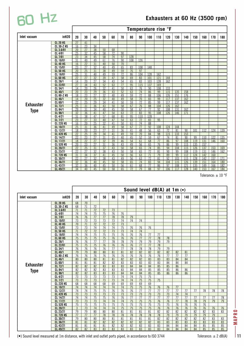
Exhausters at 60 Hz (3500 rpm)
Tolerance: ± 10 °F
Tolerance: ± 2 dB(A)
Temperature rise °FInlet vacuum inH2O
ExhausterType
CL 20 HSCL 30-Z HSCL 3.6/01CL 4/01 CL 7/01CL 10/01CL 40 HS CL 15/01CL 50 HSCL 18/01CL 60 HSCL 28/1CL 22/01CL 34/1CL 40/1CL 80-Z HSCL 46/1CL 60/1CL 72/1CL 84/1CL 98/1CL
4/21
CL 7/21
CL 220
HS
CL 10/21
CL 12/21
CL 420
HS
CL 14/21
CL 17/21
CL 520
HS
CL 20/21
CL 23/21
CL 720
HS
CL 30/21
CL 36/21
CL 42/21
CL 49/21
Sound level dB(A) at 1m (•)
ExhausterType
CL 20 HS 68 70CL 30-Z HS 68 71 72CL 3.6/01 71 71 72 72 73CL 4/01 74 74 75 75 76 76CL 7/01 76 76 77 77 78 78 79CL 10/01 73 73 73 73 73 74 74 74CL 40 HS 70 71 72 72 72 73CL 15/01 73 73 74 74 74 75 76 76 76CL 50 HS 71 72 72 72 73 73 74 74CL 18/01 74 74 75 75 75 76 76 76 77 77CL 60 HS 75 75 75 75 76 76 76 77 77 78 78CL 28/1 76 76 77 77 78 78 79 79 79 79 79CL 22/01 75 75 75 76 76 76 76 77 77 78CL 34/1 76 76 76 76 77 77 78 78 78 79 79CL 40/1 79 79 80 80 81 81 82 82 82 82 82 82 81CL 80-Z HS 76 76 76 76 76 76 76 76 76 76 77 77 77CL 46/1 80 80 80 81 81 82 82 82 83 83 83 84 84CL 60/1 81 81 81 82 82 83 83 83 83 83 84 84 84CL 72/1 82 82 82 83 83 83 84 84 84 85 85 86CL 84/1 82 82 82 83 83 83 84 84 85 85 85 86 86CL 98/1 82 82 83 83 83 84 84 84 85 85 86 86 86CL
4/21 73 73 73 73 73 74 74 75 75
CL 7/21 73 73 73 73 73 74 74 75 75 75
CL 220
HS 68 68 68 68 69 9 69 69 69
CL 10/21 74 74 74 74 74 74 75 75 76 76 76 77
CL 12/21 74 74 75 75 76 76 76 77 77 77 77 77 77 77 78 78 78
CL 420
HS 73 73 73 73 73 73 73 73 73 73 73 74 74
CL 14/21 74 74 75 75 76 76 77 77 77 77 77 77 77 77 77 77 78
CL 17/21 73 73 73 74 74 74 75 75 75 76 76 77 78 78 79 79 79
CL 520
HS 75 75 75 75 75 75 75 75 75 75 75 76 76 76 76
CL 20/21 3 73 74 74 74 75 75 75 75 76 76 76 76 76 76 76 76
CL 23/21 79 79 80 80 80 81 81 81 81 82 82 82 82 82 82 83 83
CL 720
HS 77 77 77 78 78 78 78 78 78 78 79 79 79 79 79 79
CL 30/21 79 80 80 80 81 81 81 81 81 82 82 82 82 82 82 83 83
CL 36/21 81 81 82 82 82 82 82 82 82 83 83 83 83 83 83 83 83
CL 42/21 81 81 81 81 82 82 82 83 83 83 84 84 84 84 85 85 85
CL 49/21 82 82 83 83 83 83 83 83 83 83 84 84 84 84 85 85 85
27 4116 23 3420 27 38 50 6825 32 45 58 72 9023 34 45 58 74 97 12831 40 49 61 76 90 108 12616 22 31 40 50 7023 27 32 40 49 65 83 108 14820 25 31 38 49 59 76 9725 31 40 49 59 72 86 104 128 16222 27 32 39 47 58 69 83 101 121 14414 20 27 34 43 54 65 83 103 128 16227 34 43 52 63 77 95 115 137 16914 20 26 32 41 50 63 76 90 108 13320 23 29 36 43 52 63 74 86 99 115 135 15818 23 27 32 40 49 59 72 88 106 126 151 17614 20 25 32 40 49 58 70 83 99 117 137 16222 25 29 34 41 50 59 72 85 99 117 137 16225 31 36 43 50 58 67 76 88 104 126 16229 31 34 40 45 50 58 67 77 92 108 131 16232 36 41 47 54 63 72 83 95 108 126 146 17131 38 47 57 68 81 95 110 12823 27 33 40 47 54 63 72 83 9516 20 25 32 41 50 61 74 8825 31 36 41 49 58 67 77 92 108 124 14418 20 23 27 31 36 41 48 56 63 72 81 90 101 112 124 13922 25 29 34 41 49 59 70 84 98 115 133 15322 23 27 31 35 40 45 52 59 67 74 81 90 99 110 122 13518 22 27 32 39 46 54 61 68 77 86 97 108 119 131 146 16020 23 27 31 36 43 49 56 65 76 86 99 115 135 15722 25 31 37 43 50 58 65 74 85 94 104 115 126 137 153 16922 27 32 38 43 50 58 65 72 81 90 99 108 119 131 146 16231 34 37 41 45 50 56 63 71 79 89 99 112 124 142 16022 27 32 38 43 49 56 63 72 81 92 103 115 128 142 157 17132 36 40 45 50 58 65 74 83 94 104 115 126 139 151 164 18032 36 40 45 50 56 61 68 77 86 97 108 121 135 149 166 18234 40 45 50 58 65 72 79 88 97 106 117 128 140 153 167 184
20 30 40 50 60 70 80 90 100 110 120 130 140 150 160 170 180
(•) Sound level measured at 1m distance, with inlet and outlet ports piped, in accordance to ISO 3744
Inlet vacuum inH2O 20 30 40 50 60 70 80 90 100 110 120 130 140 150 160 170 180
6
12
MAP
RO
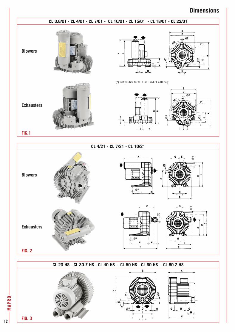
Dimensions
CL 20 HS - CL 30-Z HS - CL 40 HS - CL 50 HS - CL 60 HS - CL 80-Z HS
CL 4/21 - CL 7/21 - CL 10/21
Blowers
FIG. 2
FIG. 3
Exhausters
CL 3.6/01 - CL 4/01 - CL 7/01 - CL 10/01 - CL 15/01 - CL 18/01 - CL 22/01
(*)
(*)
Blowers
FIG.1
Exhausters
(*) feet position for CL 3.6/01 and CL 4/01 only
MAP
RO
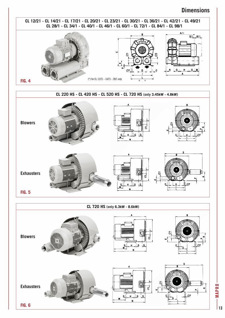
Dimensions
CL 720 HS (only 6.3kW - 8.6kW)
Blowers
Exhausters
CL 220 HS - CL 420 HS - CL 520 HS - CL 720 HS (only 3.45kW - 4.8kW)
Blowers
Exhausters
CL 12/21 - CL 14/21 - CL 17/21 - CL 20/21 - CL 23/21 - CL 30/21 - CL 36/21 - CL 42/21 - CL 49/21CL 28/1 - CL 34/1 - CL 40/1 - CL 46/1 - CL 60/1 - CL 72/1 - CL 84/1 - CL 98/1
FIG. 6
(*) for CL 12/21 - 14/21 - 28/1 onlyFIG. 4
FIG. 5
13
(*
MAP
RO
14
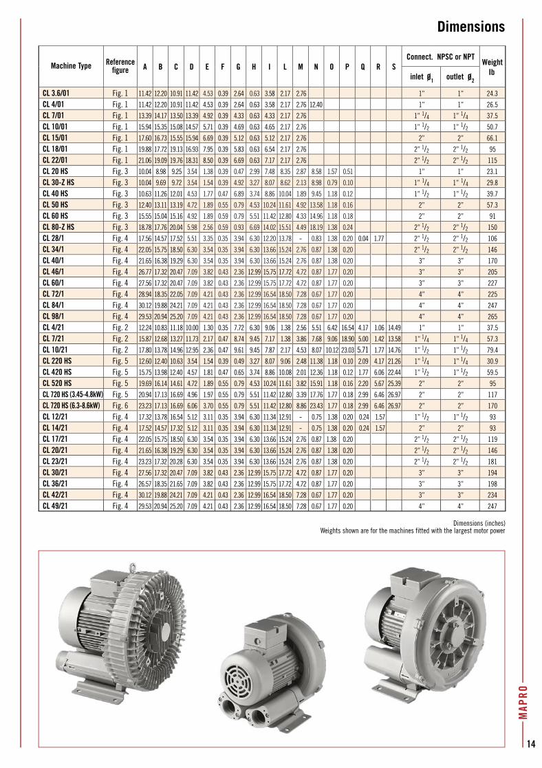
Dimensions
Machine Type Referencefigure A B C D E F G H I L M N O P Q R S
Connect. NPSC or NPTWeight
Ibinlet Ø1 outlet Ø2
CL 3.6/01 Fig. 1 11.42 12.20 10.91 11.42 4.53 0.39 2.64 0.63 3.58 2.17 2.76 1” 1” 24.3
CL 4/01 Fig. 1 11.42 12.20 10.91 11.42 4.53 0.39 2.64 0.63 3.58 2.17 2.76 12.40 1” 1” 26.5
CL 7/01 Fig. 1 13.39 14.17 13.50 13.39 4.92 0.39 4.33 0.63 4.33 2.17 2.76 1” 1/4 1” 1/4 37.5
CL 10/01 Fig. 1 15.94 15.35 15.08 14.57 5.71 0.39 4.69 0.63 4.65 2.17 2.76 1” 1/2 1” 1/2 50.7
CL 15/01 Fig. 1 17.60 16.73 15.55 15.94 6.69 0.39 5.12 0.63 5.12 2.17 2.76 2” 2” 66.1
CL 18/01 Fig. 1 19.88 17.72 19.13 16.93 7.95 0.39 5.83 0.63 6.54 2.17 2.76 2” 1/2 2” 1/2 95
CL 22/01 Fig. 1 21.06 19.09 19.76 18.31 8.50 0.39 6.69 0.63 7.17 2.17 2.76 2” 1/2 2” 1/2 115
CL 20 HS Fig. 3 10.04 8.98 9.25 3.54 1.38 0.39 0.47 2.99 7.48 8.35 2.87 8.58 1.57 0.51 1” 1” 23.1
CL 30-Z HS Fig. 3 10.04 9.69 9.72 3.54 1.54 0.39 4.92 3.27 8.07 8.62 2.13 8.98 0.79 0.10 1” 1/4 1” 1/4 29.8
CL 40 HS Fig. 3 10.63 11.26 12.01 4.53 1.77 0.47 6.89 3.74 8.86 10.04 1.89 9.45 1.18 0.12 1” 1/2 1” 1/2 39.7
CL 50 HS Fig. 3 12.40 13.11 13.19 4.72 1.89 0.55 0.79 4.53 10.24 11.61 4.92 13.58 1.18 0.16 2” 2” 57.3
CL 60 HS Fig. 3 15.55 15.04 15.16 4.92 1.89 0.59 0.79 5.51 11.42 12.80 4.33 14.96 1.18 0.18 2” 2” 91
CL 80-Z HS Fig. 3 18.78 17.76 20.04 5.98 2.56 0.59 0.93 6.69 14.02 15.51 4.49 18.19 1.38 0.24 2” 1/2 2” 1/2 150
CL 28/1 Fig. 4 17.56 14.57 17.52 5.51 3.35 0.35 3.94 6.30 12.20 13.78 - 0.83 1.38 0.20 0.04 1.77 2” 1/2 2” 1/2 106
CL 34/1 Fig. 4 22.05 15.75 18.50 6.30 3.54 0.35 3.94 6.30 13.66 15.24 2.76 0.87 1.38 0.20 2” 1/2 2” 1/2 146
CL 40/1 Fig. 4 21.65 16.38 19.29 6.30 3.54 0.35 3.94 6.30 13.66 15.24 2.76 0.87 1.38 0.20 3” 3” 170
CL 46/1 Fig. 4 26.77 17.32 20.47 7.09 3.82 0.43 2.36 12.99 15.75 17.72 4.72 0.87 1.77 0.20 3” 3” 205
CL 60/1 Fig. 4 27.56 17.32 20.47 7.09 3.82 0.43 2.36 12.99 15.75 17.72 4.72 0.87 1.77 0.20 3” 3” 227
CL 72/1 Fig. 4 28.94 18.35 22.05 7.09 4.21 0.43 2.36 12.99 16.54 18.50 7.28 0.67 1.77 0.20 4” 4” 225
CL 84/1 Fig. 4 30.12 19.88 24.21 7.09 4.21 0.43 2.36 12.99 16.54 18.50 7.28 0.67 1.77 0.20 4” 4” 247
CL 98/1 Fig. 4 29.53 20.94 25.20 7.09 4.21 0.43 2.36 12.99 16.54 18.50 7.28 0.67 1.77 0.20 4” 4” 265
CL 4/21 Fig. 2 12.24 10.83 11.18 10.00 1.30 0.35 7.72 6.30 9.06 1.38 2.56 5.51 6.42 16.54 4.17 1.06 14.49 1” 1” 37.5
CL 7/21 Fig. 2 15.87 12.68 13.27 11.73 2.17 0.47 8.74 9.45 7.17 1.38 3.86 7.68 9.06 18.90 5.00 1.42 13.58 1” 1/4 1” 1/4 57.3
CL 10/21 Fig. 2 17.80 13.78 14.96 12.95 2.36 0.47 9.61 9.45 7.87 2.17 4.53 8.07 10.12 23.03 5.71 1.77 14.76 1” 1/2 1” 1/2 79.4
CL 220 HS Fig. 5 12.60 12.40 10.63 3.54 1.54 0.39 0.49 3.27 8.07 9.06 2.48 11.38 1.18 0.10 2.09 4.17 21.26 1” 1/4 1” 1/4 30.9
CL 420 HS Fig. 5 15.75 13.98 12.40 4.57 1.81 0.47 0.65 3.74 8.86 10.08 2.01 12.36 1.18 0.12 1.77 6.06 22.44 1” 1/2 1” 1/2 59.5
CL 520 HS Fig. 5 19.69 16.14 14.61 4.72 1.89 0.55 0.79 4.53 10.24 11.61 3.82 15.91 1.18 0.16 2.20 5.67 25.39 2” 2” 95
CL 720 HS (3.45-4.8kW) Fig. 5 20.94 17.13 16.69 4.96 1.97 0.55 0.79 5.51 11.42 12.80 3.39 17.76 1.77 0.18 2.99 6.46 26.97 2” 2” 117
CL 720 HS (6.3-8.6kW) Fig. 6 23.23 17.13 16.69 6.06 3.70 0.55 0.79 5.51 11.42 12.80 8.86 23.43 1.77 0.18 2.99 6.46 26.97 2” 2” 170
CL 12/21 Fig. 4 17.32 13.78 16.54 5.12 3.11 0.35 3.94 6.30 11.34 12.91 - 0.75 1.38 0.20 0.24 1.57 1” 1/2 1” 1/2 93
CL 14/21 Fig. 4 17.52 14.57 17.32 5.12 3.11 0.35 3.94 6.30 11.34 12.91 - 0.75 1.38 0.20 0.24 1.57 2” 2” 93
CL 17/21 Fig. 4 22.05 15.75 18.50 6.30 3.54 0.35 3.94 6.30 13.66 15.24 2.76 0.87 1.38 0.20 2” 1/2 2” 1/2 119
CL 20/21 Fig. 4 21.65 16.38 19.29 6.30 3.54 0.35 3.94 6.30 13.66 15.24 2.76 0.87 1.38 0.20 2” 1/2 2” 1/2 146
CL 23/21 Fig. 4 23.23 17.32 20.28 6.30 3.54 0.35 3.94 6.30 13.66 15.24 2.76 0.87 1.38 0.20 2” 1/2 2” 1/2 181
CL 30/21 Fig. 4 27.56 17.32 20.47 7.09 3.82 0.43 2.36 12.99 15.75 17.72 4.72 0.87 1.77 0.20 3” 3” 194
CL 36/21 Fig. 4 26.57 18.35 21.65 7.09 3.82 0.43 2.36 12.99 15.75 17.72 4.72 0.87 1.77 0.20 3” 3” 198
CL 42/21 Fig. 4 30.12 19.88 24.21 7.09 4.21 0.43 2.36 12.99 16.54 18.50 7.28 0.67 1.77 0.20 3” 3” 234
CL 49/21 Fig. 4 29.53 20.94 25.20 7.09 4.21 0.43 2.36 12.99 16.54 18.50 7.28 0.67 1.77 0.20 4” 4” 247
Dimensions (inches)Weights shown are for the machines fitted with the largest motor power
MAP
RO
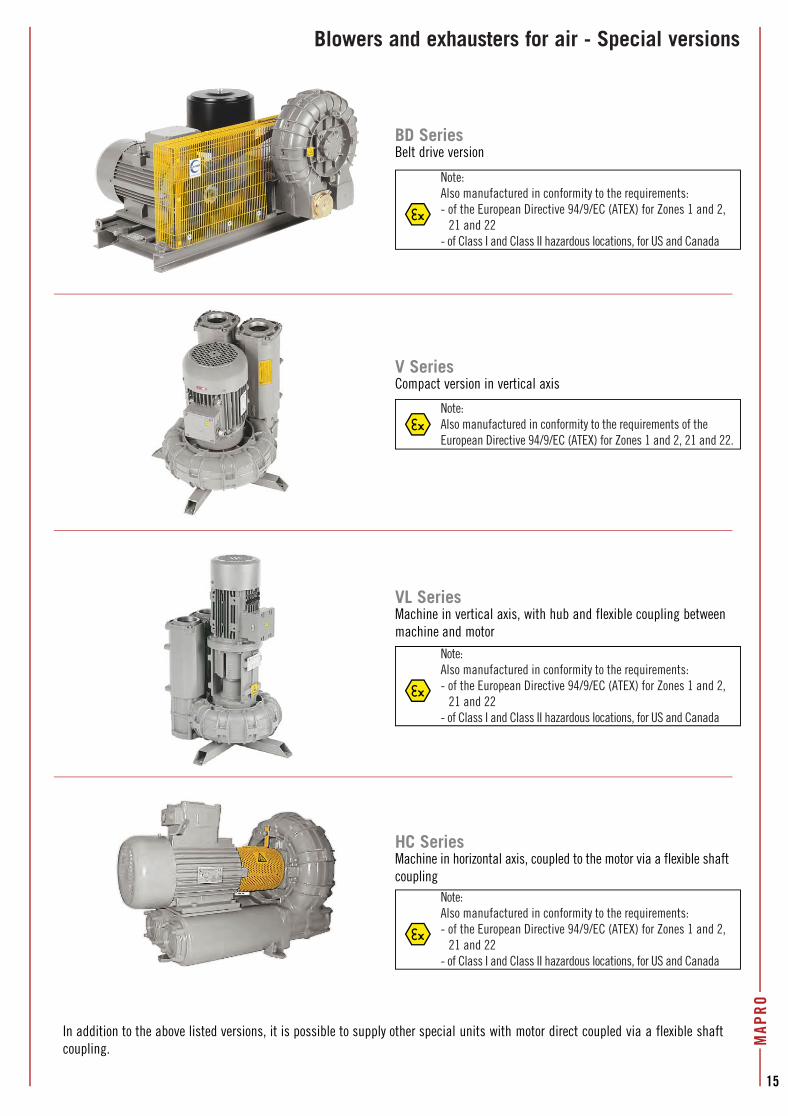
Blowers and exhausters for air - Special versions
BD SeriesBelt drive version
V SeriesCompact version in vertical axis
VL SeriesMachine in vertical axis, with hub and flexible coupling betweenmachine and motor
HC Series
In addition to the above listed versions, it is possible to supply other special units with motor direct coupled via a flexible shaft coupling.
15
Note:Also manufactured in conformity to the requirements:- of the European Directive 94/9/EC (ATEX) for Zones 1 and 2,
21 and 22- of Class I and Class II hazardous locations, for US and Canada
Note:Also manufactured in conformity to the requirements:- of the European Directive 94/9/EC (ATEX) for Zones 1 and 2,
21 and 22- of Class I and Class II hazardous locations, for US and Canada
Note:Also manufactured in conformity to the requirements:- of the European Directive 94/9/EC (ATEX) for Zones 1 and 2,
21 and 22- of Class I and Class II hazardous locations, for US and Canada
Note:Also manufactured in conformity to the requirements of the European Directive 94/9/EC (ATEX) for Zones 1 and 2, 21 and 22.
Machine in horizontal axis, coupled to the motor via a flexible shaftcoupling
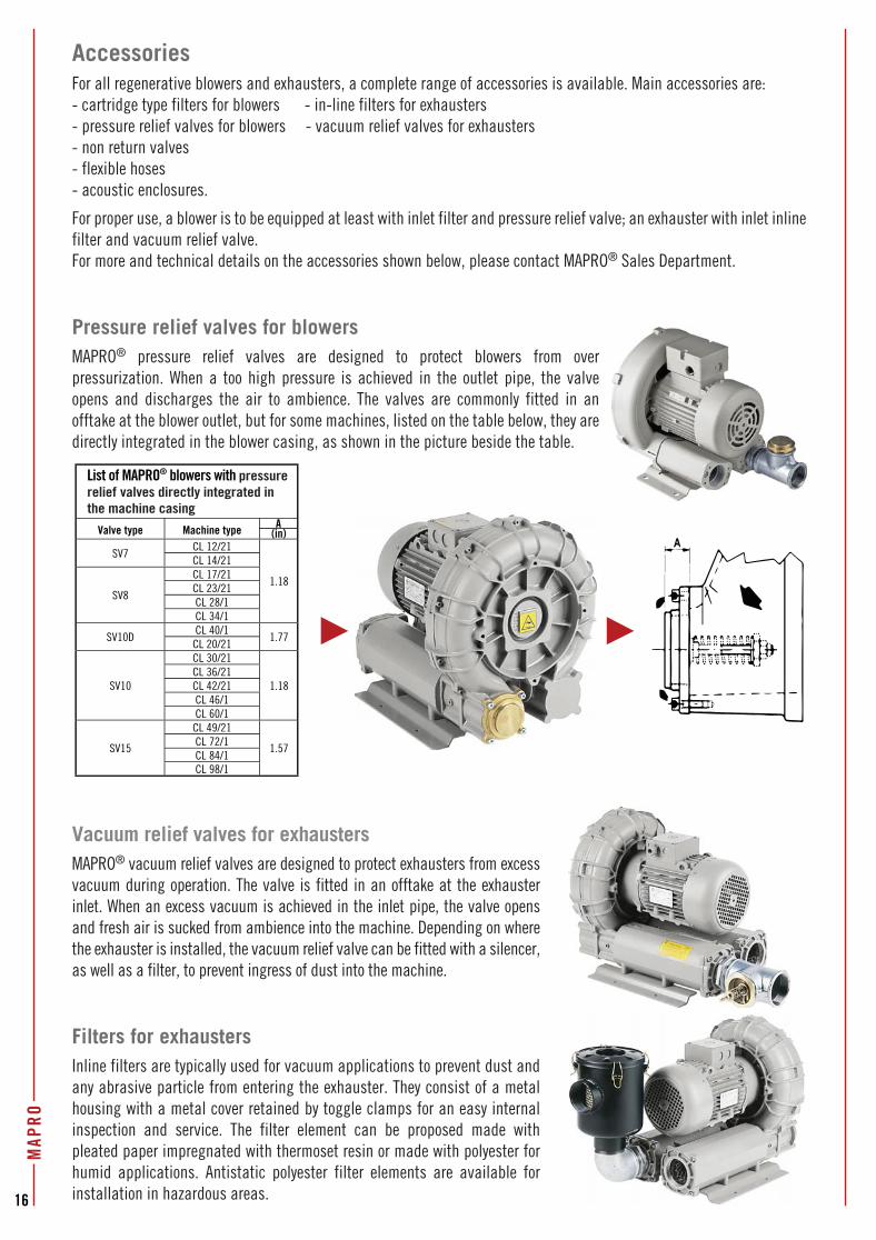
AccessoriesFor all regenerative blowers and exhausters, a complete range of accessories is available. Main accessories are:- cartridge type filters for blowers - in-line filters for exhausters- pressure relief valves for blowers - vacuum relief valves for exhausters- non return valves- flexible hoses - acoustic enclosures.
For proper use, a blower is to be equipped at least with inlet filter and pressure relief valve; an exhauster with inlet inline filter and vacuum relief valve.For more and technical details on the accessories shown below, please contact MAPRO® Sales Department.
Pressure relief valves for blowersMAPRO® pressure relief valves are designed to protect blowers from over pressurization. When a too high pressure is achieved in the outlet pipe, the valve opens and discharges the air to ambience. The valves are commonly fitted in an offtake at the blower outlet, but for some machines, listed on the table below, they are directly integrated in the blower casing, as shown in the picture beside the table.
Vacuum relief valves for exhaustersMAPRO® vacuum relief valves are designed to protect exhausters from excess vacuum during operation. The valve is fitted in an offtake at the exhauster inlet. When an excess vacuum is achieved in the inlet pipe, the valve opens and fresh air is sucked from ambience into the machine. Depending on where the exhauster is installed, the vacuum relief valve can be fitted with a silencer, as well as a filter, to prevent ingress of dust into the machine.
Filters for exhaustersInline filters are typically used for vacuum applications to prevent dust and any abrasive particle from entering the exhauster. They consist of a metal housing with a metal cover retained by toggle clamps for an easy internal inspection and service. The filter element can be proposed made with pleated paper impregnated with thermoset resin or made with polyester for humid applications. Antistatic polyester filter elements are available for installation in hazardous areas.
List of MAPRO® blowers with pressure relief valves directly integrated in the machine casing
Valve type Machine type A(in)
SV7CL 12/21
1.18
CL 14/21
SV8
CL 17/21CL 23/21CL 28/1CL 34/1
SV10DCL 40/1
1.77CL 20/21
SV10
CL 30/21
1.18CL 36/21CL 42/21CL 46/1CL 60/1
SV15
CL 49/21
1.57CL 72/1CL 84/1CL 98/1
16
MAP
RO
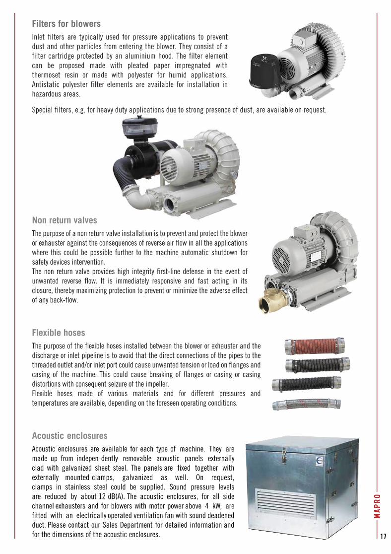
Filters for blowersInlet filters are typically used for pressure applications to prevent dust and other particles from entering the blower. They consist of a filter cartridge protected by an aluminium hood. The filter element can be proposed made with pleated paper impregnated with thermoset resin or made with polyester for humid applications. Antistatic polyester filter elements are available for installation in hazardous areas.
Special filters, e.g. for heavy duty applications due to strong presence of dust, are available on request.
Non return valvesThe purpose of a non return valve installation is to prevent and protect the blower or exhauster against the consequences of reverse air flow in all the applications where this could be possible further to the machine automatic shutdown for safety devices intervention.The non return valve provides high integrity first-line defense in the event of unwanted reverse flow. It is immediately responsive and fast acting in its closure, thereby maximizing protection to prevent or minimize the adverse effect of any back-flow.
Flexible hosesThe purpose of the flexible hoses installed between the blower or exhauster and the discharge or inlet pipeline is to avoid that the direct connections of the pipes to the threaded outlet and/or inlet port could cause unwanted tension or load on flanges and casing of the machine. This could cause breaking of flanges or casing or casing distortions with consequent seizure of the impeller.Flexible hoses made of various materials and for different pressures and temperatures are available, depending on the foreseen operating conditions.
Acoustic enclosuresAcoustic enclosures are available for each type of machine. They are made up from indepen-dently removable acoustic panels externally clad with galvanized sheet steel. The panels are fixed together with externally mounted clamps, galvanized as well. On request, clamps in stainless steel could be supplied. Sound pressure levels are reduced by about 12 dB(A). The acoustic enclosures, for all side channel exhausters and for blowers with motor power above 4 kW, are fitted with an electrically operated ventilation fan with sound deadened duct. Please contact our Sales Department for detailed information and for the dimensions of the acoustic enclosures.
MAP
RO
17
dust, are available on request.
18
MAP
RO
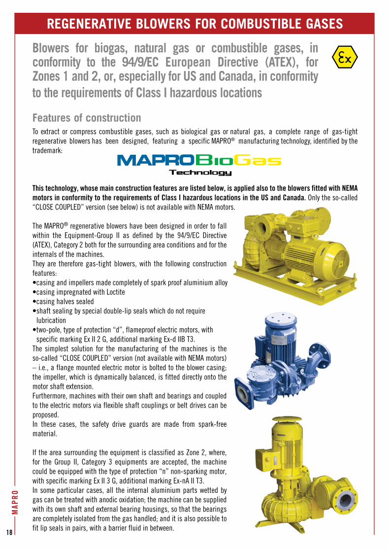
REGENERATIVE BLOWERS FOR COMBUSTIBLE GASES
Blowers for biogas, natural gas or combustible gases, in conformity to the 94/9/EC European Directive (ATEX), for Zones 1 and 2, or, especially for US and Canada, in conformity to the requirements of Class I hazardous locations
Features of constructionTo extract or compress combustible gases, such as biological gas or natural gas, a complete range of gas-tight regenerative blowers has been designed, featuring a specific MAPRO® manufacturing technology, identified by the trademark:
This technology, whose main construction features are listed below, is applied also to the blowers fitted with NEMA motors in conformity to the requirements of Class I hazardous locations in the US and Canada. Only the so-called “CLOSE COUPLED” version (see below) is not available with NEMA motors.
The MAPRO® regenerative blowers have been designed in order to fall within the Equipment-Group II as defined by the 94/9/EC Directive (ATEX), Category 2 both for the surrounding area conditions and for the internals of the machines.They are therefore gas-tight blowers, with the following construction features:•casing and impellers made completely of spark proof aluminium alloy•casing impregnated with Loctite•casing halves sealed•shaft sealing by special double-lip seals which do not require
lubrication•two-pole, type of protection “d”, flameproof electric motors, with
specific marking Ex II 2 G, additional marking Ex-d IIB T3.The simplest solution for the manufacturing of the machines is the so-called “CLOSE COUPLED” version (not available with NEMA motors) – i.e., a flange mounted electric motor is bolted to the blower casing; the impeller, which is dynamically balanced, is fitted directly onto the motor shaft extension.Furthermore, machines with their own shaft and bearings and coupled to the electric motors via flexible shaft couplings or belt drives can be proposed.In these cases, the safety drive guards are made from spark-free material.
If the area surrounding the equipment is classified as Zone 2, where, for the Group II, Category 3 equipments are accepted, the machine could be equipped with the type of protection “n” non-sparking motor, with specific marking Ex II 3 G, additional marking Ex-nA II T3.In some particular cases, all the internal aluminium parts wetted by gas can be treated with anodic oxidation; the machine can be supplied with its own shaft and external bearing housings, so that the bearings are completely isolated from the gas handled; and it is also possible to fit lip seals in pairs, with a barrier fluid in between.
s.
MAP
RO
19
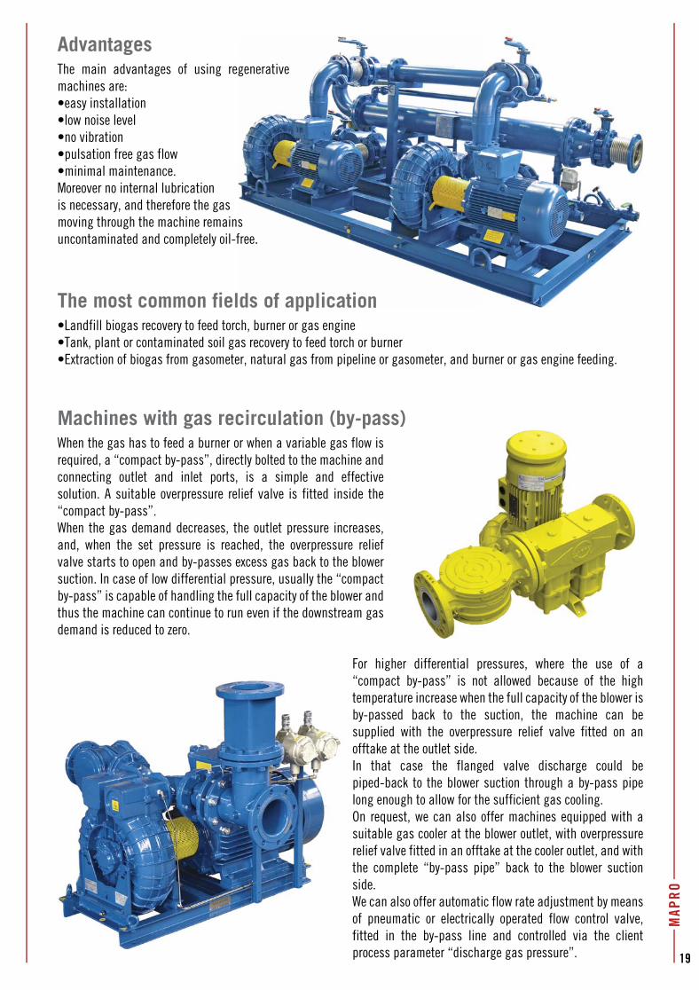
AdvantagesThe main advantages of using regenerative machines are:•easy installation•low noise level•no vibration•pulsation free gas flow•minimal maintenance.Moreover no internal lubricationis necessary, and therefore the gasmoving through the machine remains uncontaminated and completely oil-free.
The most common fields of application•Landfill biogas recovery to feed torch, burner or gas engine•Tank, plant or contaminated soil gas recovery to feed torch or burner•Extraction of biogas from gasometer, natural gas from pipeline or gasometer, and burner or gas engine feeding.
Machines with gas recirculation (by-pass)When the gas has to feed a burner or when a variable gas flow is required, a “compact by-pass”, directly bolted to the machine and connecting outlet and inlet ports, is a simple and effective solution. A suitable overpressure relief valve is fitted inside the “compact by-pass”.When the gas demand decreases, the outlet pressure increases, and, when the set pressure is reached, the overpressure relief valve starts to open and by-passes excess gas back to the blower suction. In case of low differential pressure, usually the “compact by-pass” is capable of handling the full capacity of the blower and thus the machine can continue to run even if the downstream gas demand is reduced to zero.
For higher differential pressures, where the use of a “compact by-pass” is not allowed because of the high temperature increase when the full capacity of the blower is by-passed back to the suction, the machine can be supplied with the overpressure relief valve fitted on an offtake at the outlet side.In that case the flanged valve discharge could be piped-back to the blower suction through a by-pass pipe long enough to allow for the sufficient gas cooling.On request, we can also offer machines equipped with a suitable gas cooler at the blower outlet, with overpressure relief valve fitted in an offtake at the cooler outlet, and with the complete “by-pass pipe” back to the blower suction side.We can also offer automatic flow rate adjustment by means of pneumatic or electrically operated flow control valve, fitted in the by-pass line and controlled via the client process parameter “discharge gas pressure”.
generative
s free.
ds of application
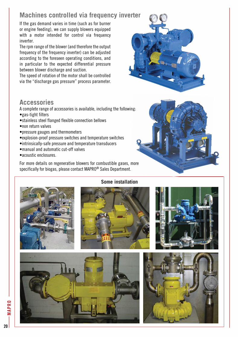
Some installation
Machines controlled via frequency inverterIf the gas demand varies in time (such as for burner or engine feeding), we can supply blowers equipped with a motor intended for control via frequency inverter. The rpm range of the blower (and therefore the output frequency of the frequency inverter) can be adjusted according to the foreseen operating conditions, and in particular to the expected differential pressure between blower discharge and suction.The speed of rotation of the motor shall be controlled via the “discharge gas pressure” process parameter.
AccessoriesA complete range of accessories is available, including the following:•gas-tight filters•stainless steel flanged flexible connection bellows•non return valves•pressure gauges and thermometers•explosion-proof pressure switches and temperature switches•intrinsically-safe pressure and temperature transducers•manual and automatic cut-off valves•acoustic enclosures.
For more details on regenerative blowers for combustible gases, more specifically for biogas, please contact MAPRO® Sales Department.
20
MAP
RO
nverter
g:
more .
20
40
100
120
140
160
180
200
220
240
260
10 60 100 400 45020 40 80 120 1800
0.5
1.5
2
2.5
3
3.5
4
4.5
5
5.5
6
6.5
7
[inH2
O]
[cfm]
30 50 140 160
60
80
200 240 280 320 360 500 550 600 900650 700
[psig
]
1
7.5
8
8.5
9
Flow rate
Outle
t pre
ssur
e
750 800 850
Outle
t pre
ssur
e
CL 46/1
CL 3.6/01
CL 4/01
CL 7/01
CL 10/01
CL 15/01
CL 18/01
CL 12/21
CL 14/21 CL 20/21CL 17/21 CL 23/21 CL 30/21 CL 36/21 CL 42/21 CL 49/21
CL 28/1
CL 22/01
CL 34/1
CL 40/1
CL 60/1
CL 72/1
CL 84/1 CL 98/1
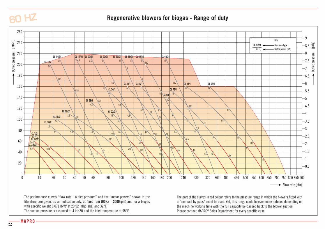
The performance curves “flow rate - outlet pressure” and the “motor powers” shown in the literature, are given, as an indication only, at fixed rpm (60Hz – 3500rpm) and for a biogas with specific weight 0.071 lb/ft3 at 29.92 inHg (abs) and 32°F.
The suction pressure is assumed at 4 inH2O and the inlet temperature at 95°F.
Key
Machine type
Motor power (kW)CL 30/21
11
Regenerative blowers for biogas - Range of duty
The part of the curves in red colour refers to the pressure range in which the blowers fitted with a “compact by-pass” could be used. Yet, this range could be even more reduced depending on the machine working time with the full capacity by-passed back to the blower suction.Please contact MAPRO® Sales Department for every specific case.
MAPRO21
9
11
13.2
11
13.2
18
18 22
4.8 9
2.65
4.8
3.6 6.6
3.6
2.65
6.6
11
9
11
3.66.6
9
9
1.8 4.81.3
6.6
1.8
4,8
2.2
3.6
1.83.6
4.8
4.83.6
1.8
1.3
2.65
0.9
2.65
0.3 1.3
0.44
1.3
0.9
0.66
3.6 4.8
3.6
4.8
2.65
3.6
2.65
3.63.6
6.6
6.6
6.6
4.84.8
9
6.6
9
6.6
9
1111
9
11
13.2
6.6
18
6.6
11913.2
13.2
11
18
9
18
13.2
COD. 0111 - CL 04-13 US
In the logic of continuous improvement, this catalogue is subject to revision. Please contact our Sales Department for information on the version in force.
"Vesuvio" Factory: Regenerative blowers and exhausters
MAPRO INTERNATIONAL SpAMacchine Pneumatiche RotativeVia Vesuvio, 220834 NOVA MILANESE (MB) - ItalyTel. +39 0362 366356Fax +39 0362 450342www.maproint.com • E-mail: [email protected]
Some field of application for MAPRO® productsAeration of waste water • Bath agitation • Suction of welding fumes • Drying process • Vacuum filtration • Fluid bed applications • Foundries • Plastic forming • Food industry • Paper converting industry • Electronic industry • Pharmaceutical industry • Textile industry • Equipments for dentist’s surgery • Air knives • Filter’s cleaning • Machines for wine-making industry • Bottling machines industry • Printing press industry • Handling by suction cups • Palletization systems • Silk-screen printing industry • Pneumatic conveyance • Plating industry • Vacuum cleaning systems • Labelling machines • Packaging machines • Fish farming oxygenation • Glasswork industry • Wood industry • Chemical petrochemical industry • Leather tanning industry
Sliding vane rotary compressors
and vacuum pumps for air and gases
Other MAPRO® products
“Cinisello” Warehouse: Goods dispatch
"Fermi" Factory: Rotary compressors