Embed Size (px)
Citation preview
Double-Stack Containers on Rail Cars: The APL View E. K. Pentimonti American President Lines Oakland, California
A brief overview is given of the development, economic benefits, operation, and terminal facility requirements of American President Lines' doublestack container rail car system.
The American President Lines' intermodal system is that it level of transportation service manner. This includes the use
(APL's) view of its provides the highest in the most efficient of stacked container
trains wherever possible. I believe that two words describe the APL intermodal system most succinctly, "innovation" and "evolution."
APL has been innovative. In terms of equipment, we have taken the existing technology of the offshore International Standards Organization (ISO) container, the over-the-road or highway trailer chassis; combined it with the technology of the double-stacked container car; and, within our own organization, developed an environment within which to establish a better system of transportation hardware. We have made significant improvements in already existing equipment technology. These efforts have resulted in a transportation system that is believed to be economically superior to other competing transportation systems.
second, our intermodal system is evolutionary. Although APL has always had a long-range strategy pertaining to general direction, the intermodal system has really evolved as we have been able to overcome physical and contractual limitations and thereby open up new opportunities for increased productivity and market penetration. As we have overcome the individual problems or hurdles of developing the doublestacked container rail car transportation system, we have been able to take advantage of the synergisms within both the international and the domestic systems.
BACKGROUND OF APL's STACKED-CAR DEVELOPMENT
Because APL has departed from all-water routes, calls at West Coast ports, and provides through bills of lading to more than 200 locations in North America, we are totally dependent on an intermodal system beyond the West Coast. To us, this system is as important as the vessels used for the carriage of international cargo. More than 65 percent of the international cargo carried through the west Coast terminals is destined for the interior or East Coast of the United States on a through bill of lading. The majority of this cargo is going via railroads to the major population centers of the United States.
Unfortunately, these international cargo flows
are tremendously imbalanced. For example, approximately 40, 000 eastbound (E/B) loads in 1985 imports went to the Northeast and fewer than 10,000 westbound (W/B) loads came back to be exported. To balance the use of container equipment, we are dependent on third parties (e.g., shippers' agents, shipper associations, freight forwarders, United Parcel Service, U.S. Postal Service) to provide us with W/B domestic freight to help reposition our containers in an economical manner.
Because of our primary reliance on the rail transportation network for cross-country cargo movement and because of the tremendous all-water (Evergreen, u.s. Lines) jumbo ship competition serving the East Coast, we are forced to become more efficient and cost competitive. Our awareness that in 1985 more than 60,000 of APL's containers were used by domestic shippers in the W/B direction only reinforced our belief that we had to do something dramatic within the intermodal system to remain in the business.
Indeed, significant changes started to occur approximately 4 years ago when we began evaluating new rail car technology in an effort to make our business more efficient. Most of the new intermodal rail car technology was oriented toward highway trailers at that time, but it was thought that we could take advantage of the lighter tare potential of a container-on-flat-car (COFC) mode, especially in the double-stacked configuration. With dedication and drive, APL spent more than a year and a half and significant resources on the further development of the double-stacked container rail car. After months of design, testing, and negotiations with various railroads about the exact details of the car, the first cars rolled off the production lines in early 1984.
APL STACK TRAIN CAR DEVELOPMENT
The following are the principal character is tics of the resultant APL stacked container car design:
l. Five-platform articulated car; 2. End-unit capabilities
•Bottom: two 20-ft or one 40-ft container; • Top: one 40-ft, one 45-ft, or one 48-ft
container; 3. Intermediate unit capabilities
•Bottom: one 40-ft container; • Top: one 40-ft, one-45 ft, or one 48-ft
container; 4. Maximum platform capacity: 103,000 lb;
79
BO
5. Car tare weight: 155,000 lbi and 6. Car length: 270 ft.
The detailed design and final development of this car were the result of many compromises and periods of mutual searching by APL and railroad colleagues in regard to the adequacy of this lightweight and innovative transportation vehicle for the intended service. However, after all the necessary design work was completed, the building and testing of the prototype units demonstrated that the concept could truly have widespread use.
Some of the key technical elements and breakthroughs in the overall design application included
• Development of a structural takes all of the tension and through the extreme outside panels
• Use of an articulated truck.
configuration that compression loads of the car.
• Use of the interbox connector (IBC), modified from the standard marine application, to tie the two containers together. This successful application saves much weight over the end bulkhead type of car an~d p·rovtdes for great flexibi-l·i-ty for handl:ing d·i-fferent sized containers stacked on the second tier.
• Because of the positive locking IBC, the top container can be an empty unit being repositioned
cannot be empty lest it be blown off by crosswinds.
ECONOMIC BENEFITS
The economic improvement rail intermodal service basics are
this equipment offers in is dramatic. Some of the
• Compared with a standard trailer-on-flatcar (TOFC) there is a 55 percent reduction in tare weight per 40-ft equivalent unit (FEU) carried 1 this prov ides a 15 to 20 percent fuel saving.
• Train size can increase dramatically in terms of total FEU carrying capacity up to 280 FEU in certain corridors (in the West, there are severe train length limitations because of passing siding length). This larger train size has the effect of spreading the line-haul labor cost component over a greater number of containers. Based on a 200-FEU or 20-car train, more than 50 percent of train crew costs per FEU can be reduced.
• Locomotive ownership cost can be reduced by more than one-third based on overall load reductions achieved for the same cargo-carrying capacityi or, conversely, more cargo can be moved with the same motive power requirements.
• Rail cars are less costly for the same carrying capacityi the cost per FEU of a stacked container car position is only 60 percent of that of a conventional COFC or TOFC FEU position.
• Reduction in maintenance expense compared with conventional cars can be realized due to the overall fewer number of wheels and trucks that need attention. A 20 to 30 percent cost reduction has been experienced to date.
In short, every cost component of a container train and its operation has been reduced by the stacked container car system.
OPERATIONS
This equipment has now been in service for almost 2 years. On March 30, 1984, the first APL stacked container train ran from Los Angeles to Chicago. Our
TRB State-of-the-Art Report 4
initial operation in 1984 included four train sets serving Los Angeles and Chicago and Seattle and New York. Since then trains have been added between Los Angeles and Atlanta, Georgia, and Oakland, California, and Chicago. Today, nine train sets, consisting of nearly 300 (five-platform) cars, are in service. This provides the most frequent E/B and W/B schedules and transit times of any available intermodal service.
The physical performance of the stacked container car has been far superior to any projections. The bad order ratio (i.e., a car taken out of service when needed) has been less than 1 percent. We are now approaching nearly 400,000 mi of utilization on the first cars in this 2-year period. It normally takes 4 years for the rail industry's highest mileage cars to reach this level of utilization. As mentioned, our projections for wheel wear were that we would change out wheels every 250,000 mi or 13 months. It now appears that we will be able to go more than 400,000 mi, which gives us confidence that both the design configuration of the articulated car, trucks, and wheels and the lightweight features are quite effective.
Ride quali.ty has been superlative. This has been one area in which we have obtained some windfall benefits as a by-product of the basic stacked container car design. Ride quality is clearly a benefit to many international and domestic cargo commodities that require a smooth ride. There are three areas in which ride quality has been improved in a stacked container car:
• Coupler slack--Fewer couplers provide for less slack action thereby protecting cargo loads from fore and aft or longitudinal accelerations. A typical 10-car stack train has only 20 couplers. In addition, end-of-car cushioning devices have been eliminated from new cars because the trains are operating as unit trains, which avoids yard handling and precludes the need for the devices. On the other hand, conventional trains have a coupler between each car with cushioning devices to provide for yard switching. This cushioning device results in 1 to 2 ft of compression at each coupling. When operating in train service, this results in slack action, which at the end of the train can accumulate to 50 to 100 ft of impact displacement.
• Lateral stability--Due to the elimination of the sway of highway chassis, the dropped-well, stacked container train cars provide an overall lower load and greater side stability than found on TOFC. Rock and roll tests conducted on a fully loaded stacked container car with a center of gravity of more than 98 in. displayed a maximum amplitude of 3.8 degrees compared with the Association of American Railroads (AAR) recommended 6-degree maximum typically found on a TOFC unit. This appears to indicate that the articulated stacked container car has intrinsic characteristics that tend to dampen rocking motion.
• Vertical vibration--The elimination of the highway chassis suspension in the container-carrying stacked car prevents the damage caused by vertical harmonic vibrations, and thereby eliminates unnecessary abrasion of the cargo.
Our customers were quick to recognize the ride benefit. There has actually been a documented Japanese manufacturer's study quantifying these ride qualities.
Nevertheless, we have continued to improve on this equipment. Since the first stacked container car was developed, the following design enhancements have been made:
Double-Stack Containers on Rail Cars
• Elimination of end-of-car cushioning. • Improved braking system with a 20 to 30 per
cent reduction in stopping distance. This ha s allowed us to increase train size, obtain speeds of 70 mph, and avoid setting hand brakes on long descending grades.
• Stronger container guides. • Added floor stringers to avoid an unsafe con
dition if cargo were to overstress the container floor.
• Permitting only one end platform to accommodate 20-ft containers in the bottom position, which reflects actual need.
• Permitting all intermediate platforms to accommodate 40- and 45-ft containers in the bottom position for future expansion of high-cube equipment.
• Addition of a reefer car design with an onboard, diesel-powered, electrical generator set capable of powering 10 (one car-full) refrigerated containers with a high degree of security, reliability, and efficiency.
COMPONENTS OF APL's STACK TRAIN SYSTEM
A successful stacked container train operation requires more than just a successful stacked container car. The infrastructure of APL's system involves many other components including equipment, management, and computer support.
Equipment
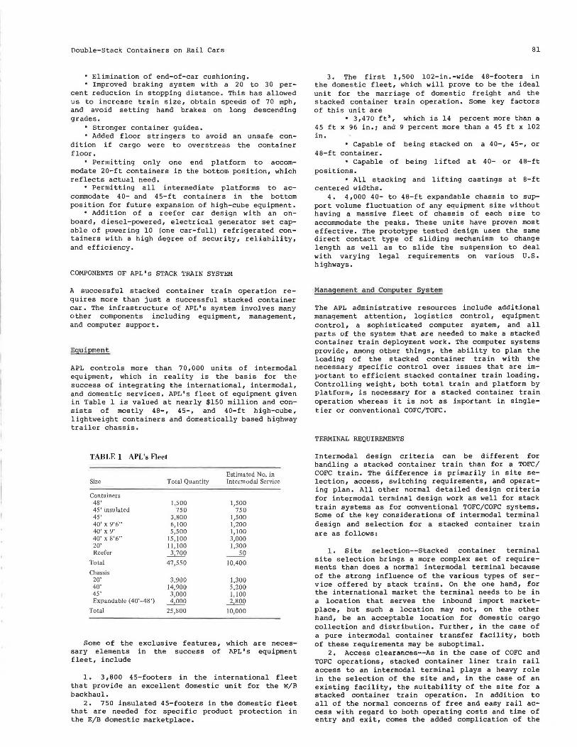
APL controls more than 7 0, 000 uni ts of intermodal equipment, which in reality is the basis for the success of integrating the international, intermodal, and domestic services. APL's fleet of equipment given in Table 1 is valued at nearly $150 million and consists of mostly 48-, 45-, and 40-ft high-cube, lightweight containers and domestically based highway traile r chassis.
TABLE 1 APL's Fleet
Estimated No. in Size Total Quantity Intermodal Service
Containers 48' 1,500 1,500 45' insulated 750 750 45' 3,800 1,500 40' x 9'6" 6,100 1,200 40' x 9' 5,500 1,100 40' x 8'6" 15,100 3,000 20' 11 , 100 1,300 Reefer 3,700 ~
Total 47,550 10,400 Chassis
20' 3,900 1,300 40' 14,900 5,200 45' 3,000 1,100 Expandable (40'-48') 4,000 2,800
Total 25,800 10,000
Some of the exclusive features, which are necessary elements in the success of APL's equipment fleet, include
1. 3 ,BOO 45-footers in the international fleet that provide an excellent domestic unit for the W/B backhaul.
2. 750 insulated 45-footers in the domestic fleet that are needed for specific product protection in the E/B domestic marketplace.
81
3. The first 1,500 102-in.-wide 48-footers in the domestic fleet, which will prove to be the ideal unit for the marriage of domestic freight and the stacked container train operation. Some key factors of th is unit are
• 3,470 ft', which is 14 percent more than a 45 ft x 96 in.i and 9 percent more than a 45 ft x 102 in.
• Capable of being stacked on a 40-, 45-, or 48-ft container.
• Capable of being lifted at 40- or 48-ft positions.
• All stacking and lifting castings at 8-ft centered widths.
4. 4,000 40- to 48-ft expandable chassis to support volume fluctuation of any equipment size without having a massive fleet of chassis of each size to accommodate the peaks. These units have proven most effective. The prototype tested design uses the same direct contact type of sliding mechanism to change length as well as to slide the suspension to deal with varying legal requirements on various U.S. highways.
Management and Computer Sys tem
The APL administrative resources include additional management attention, logistics control, equipment control, a sophisticated computer system, and all parts of the system that are needed to make a stacked container train deployment work. The computer systems provide, among other things, the ability to plan the loading of the stacked container train with the necessary specific control over issues that are important to efficient stacked container train loading. Controlling weight, both total train and platform by platform, is necessary for a stacked container train operation whereas it is not as important in singletier or conventional COFC/TOFC.
TERMINAL REQUIREMENTS
Intermodal design criteria can be different for handling a stacked container train than for a TOFC/ COFC train. The difference is primarily in site selection, access, switching requirements, and operating plan. All other normal detailed design criteria for intermodal terminal design work as well for stack train systems as for conventional TOFC/COFC systems. Some of the key considerations of intermodal terminal design and selection for a stacked container train are as follows:
l. site selection--Stacked container terminal site selection brings a more complex set of requirements than does a normal intermodal terminal because of the strong influence of the various types of service offered by stack trains. On the one hand, for the international market the terminal needs to be in a location that serves the inbound import marketplace, but such a location may not, on the other hand, be an acceptable location for domestic cargo collection and distribution . Further, in the case of a pure intermodal container transfer facility, both of these requirements may be suboptimal.
2. Access clearances--As in the case of COFC and TOFC operations, stacked container liner train rail access to an intermodal terminal plays a heavy role in the selection of the site and, in the case of an existing facility, the suitability of the site for a stacked container train operation. In addition to all of the normal concerns of free and easy rail access with regard to both operating costs and time of entry and exit, comes the added complication of the
82
vertical clearances needed. With two high-cube containers, access clearances of more than 20 ft are required to be able to flexibly operate the system.
3, Operating plan--The operating plan for a terminal requires the coordination of many physical features, including
• Track layout--With stacked container train lengths now exceeding 1.5 mi, adequate track working length must be provided to minimize the number of train breaks required. It is considered undesirable to have more than three different track breaks because of the switching effort required. A single break over two tracks is considered optimum. It is obvious that, with these train lengths, appropriate attention must be given to providing for adequate track or makeup track. Pull-through trackage arrangements provide ease in spotting train sets and are far more workable than a dead-end spur arrangement.
Actual track spacing, of course, depends on the type of operation and the equipment being used. At an end of the line, terminal tracks should be arranged to be worked singly, if possible. For full flexibility, intermediate line terminals should provide adjacent parallel track sets to accommodate direct transfers to COFC or TOFC customers.
• Container-handling equipment--Stacked container trains, because of the restricted access bottom wPll: rpq11irP. lifting PgnipmPnt th~t ll~P!=-i thP
top lift featurei that is, a device that can allow the lower parts of the container to be placed in the well without the lifter mechanism interfering with the structure of the car. Overhead cranes, port packers, and so forth are used interchangeably depending on the terminal operating mode selected. A case can be made for each of these types of equipment based on the environment of the yard.
• Storage configuration--Probably the most important decisions to be made in regard to stacked container train operations concern the yard arrangement and the flow of containers to and from the train operating area. Because of the container density of
TRB State-of-the-Art Report 4
the stacked train per linear foot, the prestaging of containers plays an important role in the efficiency of actual train operations. A case can be made for a number of basic layouts that can dramatically affect the efficiency of the loading and discharge operations. These include prestaged trackside loads and chassis, prestaged trackside chassis with center staged loads, total center staging with feed to trackside, remote staging and storage, and various combinations of these. Each scheme affects the amount of terminal equipment and labor required. Trackside prestaging for stacked container trains is obviously more complex than for conventional trains simply because there are twice as many containers per rail car platform. Most equipment is limited to a single prestaged unit trackside so, in effect, a full prestage is not practical for a stacked train operation.
• Gate--The only design consideration for a stacked container train operation in which the gate design is different from a normal terminal design is in the peak volumes expected to be handled because of the greater throughput of stacked container trains. Typically, the bottleneck during high-flow requirements can mandate greater capacity at the gate transfer function.
4. Documentation requirements--As is the case with gate operations, stacked container train operations have been shown, with their higher peak-volume requirements and larger intermodal terminals. to strain the normal systems used for the proper flow of documents.
CONCLUSION
It is hoped that these views of the business decisions, technical considerations, and operating requirements of APL's stacked container train system demonstrate our dedication to a system that we believe is the most reliable and cost-effective in the industry.