Embed Size (px)
Citation preview
1
Loading containers on double-stack cars: Multi-objective optimization models and solution
algorithms for improved safety and reduced maintenance cost
Maoxiang Lang 1, Jay Przybyla
2, Xuesong Zhou
3,*
1 School of Traffic and Transportation, Beijing Jiaotong University, P. R. China
2 Department of Civil and Environmental Engineering, University of Utah, USA
3 Department of Civil and Environmental Engineering, University of Utah, USA
122 South Central Campus Dr. CME 104
Salt Lake City, UT 84112-0561
Tel: 801-585-6590, Fax: 801-585-5477
(* corresponding author)
(Received 20 May 2011, revised 30 August 2011)
2
Loading containers on double-stack cars: Multi-objective optimization models and solution
algorithms for improved safety and reduced maintenance cost
Abstract
To improve safety measures of loading containers on double-stack rail cars, this paper develops a
multi-objective optimization model that focuses on a number of practical requirements such as the
center-of-gravity height of a loaded car and load balance considerations. A lexicographic goal
programming approach is then used to address different priorities for potentially conflicting objectives
and constraints. To minimize the center-of-gravity height, a linear-fractional programming technique is
adopted in this study to transform the corresponding generalized mixed integer fractional problem into a
sequence of mixed integer linear subproblems. A tabu search algorithm is proposed to get the
close-to-optimal solutions of the large-scale double-stack car loading problems. Based on a set of
matching and assigning rules, this paper further presents a two-stage heuristic algorithm for solving
large-scale double-stack car loading problems. A real-world case study is used to examine the efficiency
and effectiveness of the proposed optimization and heuristic procedures.
Keywords: Double-stack container loading; Multiple-objective optimization; Lexicographic goal
programming; Linear-fractional programming; Heuristic algorithms
1. Introduction
Containerization provides an efficient and economic means of transporting goods. The vast majority
of manufactured commodities moving via international trade are shipped in ocean-going containers,
and the rail-truck intermodal segment plays an important role for regions that rely heavily on and wish
to engage in emerging global markets. In recent decades, the growing international trade volumes have
created many challenges for railroad systems around the world. As many rail terminals currently are
running at or near capacity, railroad industries have responded to these challenges with new
technological improvements, such as, double-stack intermodal train services. Introduced in 1984 from
U.S West Coast ports, the double-stack train service allows containers to be stacked two high
(double-stacked) so that freight containers are shipped more efficiently.
Double-stack container trains have been running in many countries including in the United States,
Canada, and Australia. One important consideration in the double-stack container rail service model is
that centers of gravity of loaded double-stack cars are much higher than those of regular rail cars and
are variable. This raises significant concerns on the stability and related operational safety of
double-stack container trains.
The center of gravity is a single point through which all forces affecting the rail car act. The
vertical location of the center of gravity is of particular importance when examining the rail car’s
lateral stability. As a rail car runs on curve lines, a lateral force is created at the wheels causing it to
turn. This force is opposed by an equal and opposite force, called a centrifugal force, which drives the
rail car toward the outside of the curve lines. To counteract the centrifugal force, rails are superelevated
in corners to allow the train to transverse the curve lines faster. Nadal’s formula shown in Equation (1)
(APTA 2007, USDOT-FRA 2011), used in railway design, relates the downward force exerted by the
train’s wheels on the rail to the lateral force of the wheels flange against the face of the rail.

3
tan( )
1 tan( )
L
V
(1)
where L and V refer to the lateral and vertical forces acting upon the rail and wheel, δ is the angle
made when the wheel flange is in contact with the rail face, and μ is the coefficient of friction between
the wheel and the rail.
Typically in railway design, it is desirable to have twice as much downward force than lateral force.
This design standard governs the speed at which the trains can transverse specific curves. For a rail
car to remain in equilibrium when traversing a curve, the resultant of the weight and the centrifugal
force must be within the track width as in Fig 1B. In this situation, the resultant of the weight and
normal forces are directed toward the center of the track, so that the load is distributed equally on the
two rails.
When a train traverses a superelevated curve at a speed that is greater than recommended, and or
when the center of gravity of the rail car is excessively high, it can lead to an overbalanced situation as
seen in Fig 1C. As the train runs on curve lines, the weight and centrifugal forces act together at the
center of gravity resulting in the green resultant force. This resultant force is directed away from the
center of the track toward the high rail. The L/V ratio on the high rail tends to increase with speed
and may result in wheel climb or rollover (Dukkipati 1988, AREMA 2003, Holowaty 2004, Loumiet
2005).
When a train traverses a superelevated curve at a speed that is less than recommended, and or when
the center of gravity of the rail car is excessively high, it can lead to an underbalanced situation as seen
in Fig 1A. In this case, the centrifugal forces are insignificant and the resultant force is shown by the
green lines for both low and high centers of gravity. The resultant force is directed toward the low rail,
resulting in unloading of the high rail to a critical point where the entire vertical load is on the lower
rail and the high wheels lift off. In summary, the higher the center of gravity is, the more critical the
underbalanced situation can be (Dukkipati 1988, AREMA 2003, Holowaty 2004, Loumiet 2005).
Figure 1. Underbalanced, Equilibrium, and Overbalanced train cars (adapted from Dukkipati 1988 and
AREMA 2003)
The significance of cross-wind loading on rail cars leading to overturning has been extensively
researched recently. When a train is exposed to cross-winds, there will be an aerodynamic loading on

4
the train creating a moment about the opposite rail. The weight of the rail car is the only stabilizing
force, and if the train is running in a curve in an underbalanced situation, then the wind load will add to
the overturning potential of the train. Rail cars with higher centers of gravity will be especially
susceptible to the potential of overturning due to wind loads because the moment arm is increased,
resulting in greater overturning forces (Gawthorpe 1994, RGS 1994, Schulte-Werning 1997, Fujii 1999,
Lippert 1999, Lippert 2000, Matschke 2000, Andersson 2001, Cleon 2001, Brandbury 2003, Gautier
2003, Mancini 2003, Anderson 2004).
Just as the vertical location of the center of gravity of each rail car is of critical importance when
considering the safety of the train, likewise, the location of the horizontal center of gravity for each rail
car is also important. A concentration of loads on one end of a rail car tends to unload the wheels on
the opposite end of the car. Although the weight of this type of load is typically insufficient to cause
wheel lift by itself, when combined with the dynamic forces of train action, it will cause the car to be
more susceptible to train dynamic forces which lead to derailment (Dukkipati 1988, Loumiet 2005).
Our paper aims to systematically improve the important safety performance of feasible solutions that
already satisfy the technical loading requirements, as any feasible solution can still have a very small
probability of rail derailments which are associated with huge safety and operational impacts.
The safety issues associated with maintaining the lowest centers of gravity as possible on rail cars is
clear. A less obvious, but equally important aspect of maintaining lower centers of gravity on rail cars,
is reducing maintenance costs. There are so few trail derailments (relatively speaking) but the literature
suggests that a lower center of gravity of rail cars lowers wear and tear and reduces maintenance costs.
The ideal running condition for each train is in equilibrium. When a train is running out of
equilibrium, excessive stresses occur on the trains and railways. While train overturning and/or
derailment may not occur in each safety circumstance mentioned above, excessive car and track
damage is occurring (AREMA 2003, Loumiet 2005).
The importance of providing rail cars with lower centers of gravity is embraced by industry as seen
in the manufacturing and marketing of new rail cars. For example, Talgo America and Freight Car
America have newer rail cars available that specifically tout their lower centers of gravity which
provide increased safety and lower maintenance costs (Freight Car America Inc. 2011, Tlago Inc. 2011).
Although the lower centers of gravity are nominal compared to other or previous models, the safety and
maintenance implications are still credible. Double stack containers are more difficult to maintain
lower centers of gravity due to the changing and random nature of loadings. Union Pacific Railroad,
Norfolk Southern, and BNSF each have specific loading rules to follow when stacking double-stack
rail cars (Norfolk Southern 1999, BNSF 2005, UP 2010). These rules, however, are simplistic and
will not provide an optimization of vertical and horizontal centers of gravity. The U.S. Department of
Transportation Federal Railroad Administration (FRA) reported that it is needed to develop and
implement stricter guidelines for train make-up (weight loading). The current standards the railroad
industry follows are potentially insufficient and the FRA can step in and encourage more conservative
practices if it is deemed necessary (USDOT-FRA 2005).
To improve safety measures and reduce maintenance cost, this paper develops a multi-objective
optimization model of double-stack rail car loading problem by taking the center-of-gravity heights and
load balances of loaded cars into consideration. This study also aims to develop computationally
efficient algorithms for solving the double-stack car loading problem. This paper is organized as
follows. After this introductory Section and the literature review in Section 2, Section 3 describes
detailed background information and some technical requirements of the double-stack railcar loading

5
problem. Section 4 presents a multi-objective optimization model for double-stack car loading. A
lexicographic goal programming approach is then proposed in Section 5. This approach is able to
handle the trade-offs between different and potentially conflicting objectives so that the developed
models can be solved by using an optimization software package GAMS (Rosenthal, 2008). In order to
optimize the height of the center of gravity, a linear-fractional technique is used to transform the
generalized mixed integer linear-fractional programming problem into a sequence of mixed integer
linear subproblems. Section 6 presents a tabu search algorithm for solving the double-stack railcar
loading problem by generating an initial solution randomly and improving the solutions using 2-opt
and tabu list techniques. In section 7, a two-stage heuristic algorithm is designed to solve the real-world
instances according to a set of matching and assigning rules. Computational experiments are conducted
in Section 8 to demonstrate the effectiveness and efficiency of the proposed algorithms.
2. Literature review
Research has been conducted into to the problem of optimizing the stacking of containers on rail cars.
In an early study, Jahren and Rolle (1994) presented a computerized assignment algorithm for the
double-stack railcar loading problem. They acknowledged that an assignment-type mathematical model
could be developed, but priority-based heuristic solution algorithms were more suitable when precise
information (e.g. about container weights and container destinations) was unavailable. Pacanovsky et al.
(1995) described a prototype of a decision support system with different loading strategies related to
the load factor, center of gravity, and uniformity in platform loads. Jahren et al. (1995) developed two
automatic suggestion heuristic algorithms to improve the load quality of double-stack trains, namely a
container-oriented method, and a location-oriented method. Essentially, these previous studies focus on
heuristic algorithms of assigning containers to cars based on a set of loading strategies, but limited
attention has been paid to the development of mathematical models for the double-stack car loading
problem. In fact, there is a great need to construct and solve the optimization model, as an optimal
assignment solution provides an exact benchmark for systematically testing various heuristic
algorithms and alternative loading strategies.
The double-stack rail car loading problem is a variant of the Multiple Container Packing Problem
(MCPP) in which containers can be viewed as items and double-stack cars can be viewed as general
containers. Additional constraints/objectives can be developed to include and optimize load balance
and the center-of-gravity heights of loaded cars. The multiple containers packing problem is known to
be an NP hard problem. When optimal solutions are unattainable for large-scale and complex instances,
the heuristic approach is typically used to generate close-to-optimal solutions. For example, a genetic
algorithm was presented by Raidl and Kodydek (1998), and an adaptive link adjustment evolutionary
algorithm was developed by Soak et al. (2008).
The double-stack car loading problem has some structural similarities and inherent linkages with the
container loading problems on cargo ships and in airplanes, which also aim to maximize the total
payload within limited space. Imai et al. (2006) studied the stowage and loading plan for a container
ship in which both the ship stability and the number of container re-handling are taken into account. In
their study, the center of gravity was used as one of the safety constraints. Mongeau and Bes (2003)
addressed the aircraft container loading problem in which a satisfactory distribution of the center of
gravity of the aircraft was set as a hard constraint other than a (secondary) objective. From a
multi-criteria optimization point of view, this paper specifically considers the center-of-gravity height
6
and the load balancing as the second and third objectives of the double-stack car loading problem.
3. Background information
To clearly describe loading patterns in the proposed mathematical model, this section starts with a
background introduction to basic configurations of double-stack cars and containers, and then discusses
the related technical requirements for loading containers on double-stack cars. Many detailed model
inputs in this study are based on the specific considerations in China which are: (i) the payload of a car,
(ii) the center-of-gravity height of a loaded car, and (iii) the load difference between two sets of loaded
cars. Despite this model being specific to Chinese requirement, the proposed modeling methodology
and solution algorithms can easily be adapted to the practice of other countries.
3.1. Basic configurations of double-stack cars
Double-stack rail cars are cars that allow containers to be stacked two high. These cars may be single,
two, three, or five platform units that are articulated above shared trucks (more detailed descriptions
can be found in the study by Jahren and Rolle, 1994). While the three or five-platform double-stack
cars are popular in North America, due to the axle load limitation, double-stack cars in China are all
manufactured with single platform.
There are two typical types of double-stack cars: Bulkhead and Interbox Connector (IBC). Bulkhead
cars have risers at the ends of each platform that support the top container, while IBC cars rely on hand
placed connectors between the bottom and top containers to lock the top container into place. With an
IBC car, the weight of the top container is supported by the bottom container(s). IBC cars offer several
advantages such as lower tare weights, higher load capacities, and the ability to load containers that are
longer than 40 feet. Double-stack cars in China are all IBC cars, and their key parameters are shown in
Table 1.
Table 1. Basic configurations of double-stack cars in China.
Maximal
payload
Tare weight Total length Length of
platform
Height of
platform from
rail surface
Height of
center-of-gravity
of empty car
from the rail
surface
78 tons 22 tons 19,466 mm 12,300 mm 290 mm 650 mm
Containers capable of being loaded on double-stack rail cars in China primarily include 20 ft and 40
ft International Organization for Standardization (ISO) containers.
3.2. Loading patterns of double-stack cars
To balance the loads of the two wheelsets of the double stack cars, the following two combinations
are considered as infeasible in practice, i.e., two 20ft containers on the bottom and one 20 ft container
on the top, and one 40ft container on the bottom and one 20 ft container on the top. So there are six
possible combinations to load 20 ft ISO and 40 ft ISO containers onto double-stack cars:

7
(1) two 20 ft containers on the bottom and one 40 ft container on the top shown in Figure 2;
(2) only two 20 ft containers on the bottom shown in Figure 3;
(3) only one 40 ft container on the bottom shown in Figure 4;
(4) one 40 ft container on the bottom and another 40 ft container on the top;
(5) one 40 ft container on the bottom and two 20 ft containers on the top; and
(6) two 20 ft containers on the bottom and the other two 20 ft containers on the top.
To ensure the power collecting effect of electrified locomotives from the cable suspension wire on
double-stack service lines, the height of the cable suspension wire should not exceed 6,330 mm, given
the fixed heights of electrified locomotives. To avoid the electric shock to the double-stack trains, the
maximal height of the loading-gauge (i.e. vertical clearance) of the electrified double-stack lines is
5,850 mm in China. As the height of a 40 ft container is 2,896 mm, and the height of the platform of a
double-stack car is 290 mm. The 4th
loading pattern of one 40 ft container on another 40 ft container
leads to a total loading height of over 6,080 mm (> 5,850 mm), so this pattern is not allowed in China.
For the 5th
loading pattern, the two 20 ft containers on the top are difficult to secure. When
considering the maximal gross weight of a 20 ft container is 30.48 tons and the payload of a
double-stack car is only 78 tons, loading pattern (6) gives an average load factor (or capacity factor) of
61.1% of each 20 ft container, which leads to an uneconomical option. As a result, there are only three
permissive loading patterns of double-stack cars in China: (1) two 20 ft containers on the bottom, one
40 ft container on the top; (2) only two 20 ft containers on the bottom; and (3) only one 40 ft container
on the bottom.
H4
0
Hc
H2
0
Hp
Figure 2. Loading pattern (1)
H2
0
Hp
Figure 3. Loading pattern (2)

8
H4
0
Hp
Figure 4. Loading pattern (3)
Accordingly, the following technical loading standards are currently used in China.
(1) The total gross weight of the containers loaded on a double-stack car should not exceed the
maximal payload of the car, namely 78 tons.
(2) The center-of-gravity height of a loaded double-stack car should not exceed 2,400 mm.
(3) The weight difference between the two 20 ft containers on the bottom of a car should not exceed
10 tons.
4. Optimization model
The following notation is used to formulate the container loading problem on double-stack rail cars
problem with center-of-gravity considerations.
4.1. Notations
(1) Indices/Constants/Parameters
i = 20 ft container index;
j = 40 ft container index;
k = double-stack car index;
I = total number of 20 ft containers;
J = total number of 40 ft containers;
K = total number of double-stack cars;
20
iW = gross weight of the ith
20 ft container, i=1, … , I ;
40
jW = gross weight of the jth
40 ft container, j=1, … , J ;
Wcar = tare weight of a double-stack rail car;
Hp = height of the platform of the double-stack rail car from the rail surface;
Hc = height of the interbox connector between the top and the bottom containers, not
including the two ends plugging into the corner fittings of the upper and lower containers. Generally,
Hc =30 mm;
H20 = height of a 20 ft container;
H40 = height of a 40 ft container;
Hcar = center-of-gravity height of an empty double-stack rail car from the rail surface;
P = maximal payload of a double-stack car;
H = maximal allowed center-of-gravity height of the loaded double-stack car;
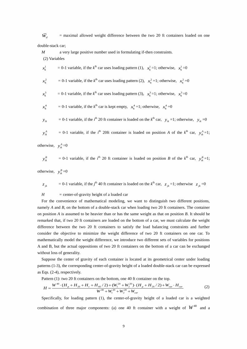
9
dW = maximal allowed weight difference between the two 20 ft containers loaded on one
double-stack car;
M a very large positive number used in formulating if-then constraints.
(2) Variables
1
kx = 0-1 variable, if the kth
car uses loading pattern (1), 1
kx =1; otherwise, 1
kx =0
2
kx = 0-1 variable, if the kth
car uses loading pattern (2), 2
kx =1; otherwise, 2
kx =0
3
kx = 0-1 variable, if the kth
car uses loading pattern (3), 3
kx =1; otherwise, 3
kx =0
4
kx = 0-1 variable, if the kth
car is kept empty, 4
kx =1; otherwise, 4
kx =0
iky = 0-1 variable, if the ith
20 ft container is loaded on the kth
car, iky =1; otherwise,
iky =0
A
iky = 0-1 variable, if the ith
20ft container is loaded on position A of the kth
car, A
iky =1;
otherwise, A
iky =0
B
iky = 0-1 variable, if the ith
20 ft container is loaded on position B of the kth
car, B
iky =1;
otherwise, B
iky =0
jkz = 0-1 variable, if the jth
40 ft container is loaded on the kth
car, jkz =1; otherwise
jkz =0
H = center-of-gravity height of a loaded car
For the convenience of mathematical modeling, we want to distinguish two different positions,
namely A and B, on the bottom of a double-stack car when loading two 20 ft containers. The container
on position A is assumed to be heavier than or has the same weight as that on position B. It should be
remarked that, if two 20 ft containers are loaded on the bottom of a car, we must calculate the weight
difference between the two 20 ft containers to satisfy the load balancing constraints and further
consider the objective to minimize the weight difference of two 20 ft containers on one car. To
mathematically model the weight difference, we introduce two different sets of variables for positions
A and B, but the actual oppositions of two 20 ft containers on the bottom of a car can be exchanged
without loss of generality.
Suppose the center of gravity of each container is located at its geometrical center under loading
patterns (1-3), the corresponding center-of-gravity height of a loaded double-stack car can be expressed
as Eqs. (2-4), respectively.
Pattern (1): two 20 ft containers on the bottom, one 40 ft container on the top. 40 20 20
20 40 1 2 20
40 20 20
1 2
( / 2) ( ) ( / 2)
p c p car car
car
W H H H H W W H H W HH
W W W W
(2)
Specifically, for loading pattern (1), the center-of-gravity height of a loaded car is a weighted
combination of three major components: (a) one 40 ft container with a weight of 40W and a

10
center-of-gravity height as 20 40( / 2)p cH H H H , (b) two 20 ft containers with a weight of
20 20
1 2( )W W and a center-of-gravity height as 20( / 2)pH H , and (c) an empty car with a weight
of carW and a center-of-gravity height as carH .
Pattern (2): two 20 ft containers on the bottom
20 20
1 2 20
20 20
1 2
( ) ( / 2)
p car car
car
W W H H W HH
W W W
(3)
Pattern (3): one 40 ft container on the bottom
40
40
40
( / 2)
p car car
car
W H H W HH
W W
(4)
4.2. Problem Statement
Given a set of double-stack rail cars, a set of 20 ft containers and a set of 40 ft containers, the
double-stack car loading problem under consideration aims to assign more 40 ft and 20 ft containers to
the cars, and a container-car assignment should be either one of the above three feasible loading
patterns.
In this study, we consider the following three objectives.
(1) Maximize the TEUs loaded, where TEU stands for Twenty-foot Equivalent Unit, i.e., 1 TEU
equals to one 20 ft container, then one 40 ft container equals to 2 TEUs.
(2) Lower the center-of-gravity heights of loaded double-stack cars.
(3) Balance the loads of the containers on double-stack cars.
To make the double-stack transport service more profitable, we set the first objective with the highest
priority. As the center-of-gravity height is one of the most important factors regarding the operational
safety of double-stack trains, this study assigns it as the second priority. The third objective of load
balancing is considered as a secondary safety goal and it is assigned as the third priority. It should be
remarked that, the corresponding hard constraints (originated from standard of practice) on the maximal
payload, the maximal center-of-gravity height and the maximal weight difference between the two 20 ft
containers on a car are included in the proposed optimization model.
4.3. Optimization model
(1) Objective functions
(a) Maximize TEUs loaded
=1 1 1
( 2 )K I J
ik jk
k i j
Max y z
(5)
Equation (5) aims to maximize the load factor of double-stack cars. Specifically,
1
I
ik
i
y
and
1
J
jk
j
z
are the numbers of 20 ft containers and 40 ft containers, respectively, loaded on the kth
car. A
11
coefficient of 2 is used here to convert the number of 40 ft containers 1
J
jk
j
z
to the number of TEUs.
(b) Lower the centers of gravity of loaded cars
1
K
Kk
Min Max H
(6)
where kH is the center-of-gravity height of the kth
car:
40 20 40 3
j 20 40 i 20 j 20
1 1 1
40 20
j i
1 1
( ) ( / 2) ( ) ( / 2) ( ) ( )
( ) ( )
J I J
jk p c ik p car car jk c k
j i j
k J I
jk ik car
j i
z W H H H H y W H H W H z W H H x
H
z W y W W
(7)
Equation (6) minimizes the maximal center-of-gravity height among all cars. In Equation (7), the
fraction term corresponds to the center-of-gravity height of the kth
car under all loading patterns,
extended from Eqs. (2-4) by adding the decision variables 3
kx , iky and jkz .
(c) Minimize the weight difference of 20 ft containers under loading patterns (1) and (2)
( ) (20 20
11 1
)I IK
A B
ik i ik ik
i i
Min Max y W y W
(8)
Equation (8) is intended to minimize the maximal weight difference of the two 20 ft containers on
one car among all cars loaded with 20 ft containers. In this equation, 20
1
IA
ik i
i
y W
( ) and
20
1
)I
B
ik i
i
y W
( represents the weight of the 20 ft container on position A and position B, respectively,
of the kth
car. By definition, the 20 ft container on position A is heavier than or has the same weight as
that on position B, shown in Equation (19) later.
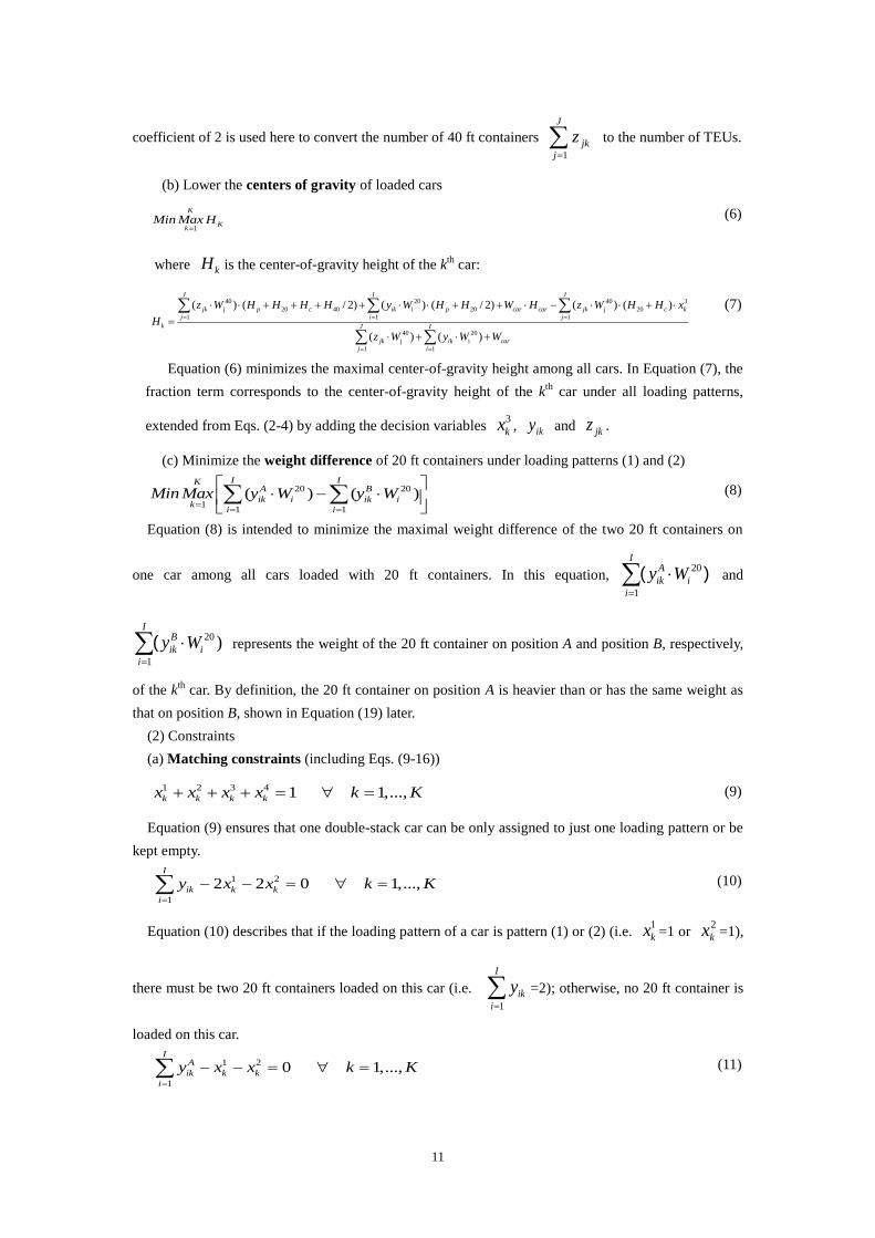
(2) Constraints
(a) Matching constraints (including Eqs. (9-16))
1 2 3 4 1 1,...,k k k kx x x x k K (9)
Equation (9) ensures that one double-stack car can be only assigned to just one loading pattern or be
kept empty.
1 2
1
2 2 0 1,...,I
ik k k
i
y x x k K
(10)
Equation (10) describes that if the loading pattern of a car is pattern (1) or (2) (i.e. 1
kx =1 or 2
kx =1),
there must be two 20 ft containers loaded on this car (i.e.
1
I
ik
i
y
=2); otherwise, no 20 ft container is
loaded on this car.
1 2
1
0 1,...,I
A
ik k k
i
y x x k K
(11)
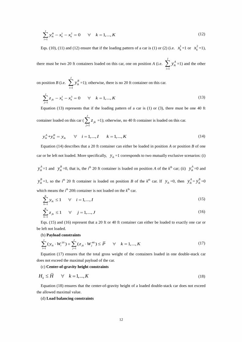
12
1 2
1
0 1,...,I
B
ik k k
i
y x x k K
(12)
Eqs. (10), (11) and (12) ensure that if the loading pattern of a car is (1) or (2) (i.e. 1
kx =1 or 2
kx =1),
there must be two 20 ft containers loaded on this car, one on position A (i.e.
1
IA
ik
i
y
=1) and the other
on position B (i.e.
1
IB
ik
i
y
=1); otherwise, there is no 20 ft container on this car.
1 3
1
0 1,...,J
jk k k
j
z x x k K
(13)
Equation (13) represents that if the loading pattern of a car is (1) or (3), there must be one 40 ft
container loaded on this car (1
J
jk
j
z
=1); otherwise, no 40 ft container is loaded on this car.
+ 1,..., 1,...,A B
ik ik iky y y i I k K (14)
Equation (14) describes that a 20 ft container can either be loaded in position A or position B of one
car or be left not loaded. More specifically, iky =1 corresponds to two mutually exclusive scenarios: (i)
A
iky =1 and B
iky =0, that is, the ith
20 ft container is loaded on position A of the kth
car; (ii) A
iky =0 and
B
iky =1, so the ith
20 ft container is loaded on position B of the kth
car. If iky =0, then A
iky =B
iky =0
which means the ith
20ft container is not loaded on the kth
car.
1
1 1,...,K
ik
k
y i I
(15)
1
1 1,...,K
jk
k
z j J
(16)
Eqs. (15) and (16) represent that a 20 ft or 40 ft container can either be loaded to exactly one car or
be left not loaded.
(b) Payload constraints
20 40
1 1
( ) ( ) 1,...,I J
ik i jk j
i j
y W z W P k K
(17)
Equation (17) ensures that the total gross weight of the containers loaded in one double-stack car
does not exceed the maximal payload of the car.
(c) Center-of-gravity height constraints
1,...,kH H k K (18)
Equation (18) ensures that the center-of-gravity height of a loaded double-stack car does not exceed
the allowed maximal value.
(d) Load balancing constraints
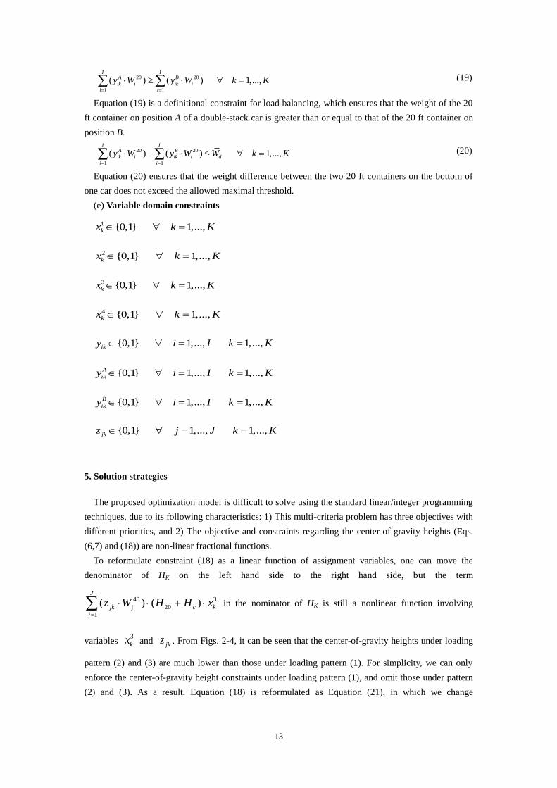
13
20 20
1 1
( ) ( ) 1,...,I I
A B
ik i ik i
i i
y W y W k K
(19)
Equation (19) is a definitional constraint for load balancing, which ensures that the weight of the 20
ft container on position A of a double-stack car is greater than or equal to that of the 20 ft container on
position B.
20 20
1 1
( ) ( ) 1,...,I I
A B
ik i ik i d
i i
y W y W W k K
(20)
Equation (20) ensures that the weight difference between the two 20 ft containers on the bottom of
one car does not exceed the allowed maximal threshold.
(e) Variable domain constraints
1 {0,1} 1,...,kx k K
2 {0,1} 1,...,kx k K
3 {0,1} 1,...,kx k K
4 {0,1} 1,...,kx k K
{0,1} 1,..., 1,...,iky i I k K
{0,1} 1,..., 1,...,A
iky i I k K
{0,1} 1,..., 1,...,B
iky i I k K
{0,1} 1,..., 1,...,jkz j J k K
5. Solution strategies
The proposed optimization model is difficult to solve using the standard linear/integer programming
techniques, due to its following characteristics: 1) This multi-criteria problem has three objectives with
different priorities, and 2) The objective and constraints regarding the center-of-gravity heights (Eqs.
(6,7) and (18)) are non-linear fractional functions.
To reformulate constraint (18) as a linear function of assignment variables, one can move the
denominator of HK on the left hand side to the right hand side, but the term
40 3
j 20
1
( ) ( )J
jk c k
j
z W H H x
in the nominator of HK is still a nonlinear function involving
variables 3
kx and jkz . From Figs. 2-4, it can be seen that the center-of-gravity heights under loading
pattern (2) and (3) are much lower than those under loading pattern (1). For simplicity, we can only
enforce the center-of-gravity height constraints under loading pattern (1), and omit those under pattern
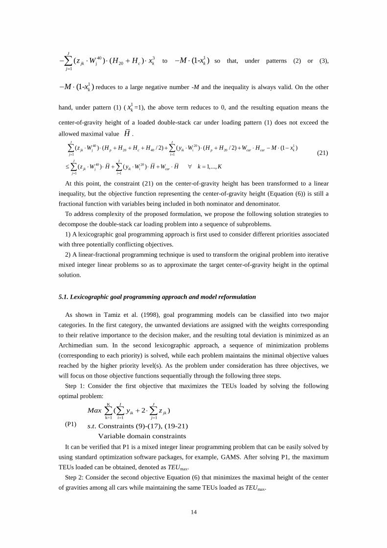
(2) and (3). As a result, Equation (18) is reformulated as Equation (21), in which we change
14
40 3
j 20
1
( ) ( )J
jk c k
j
z W H H x
to 1(1- )kM x so that, under patterns (2) or (3),
1(1- )kM x reduces to a large negative number -M and the inequality is always valid. On the other
hand, under pattern (1) (1
kx =1), the above term reduces to 0, and the resulting equation means the
center-of-gravity height of a loaded double-stack car under loading pattern (1) does not exceed the
allowed maximal value H .
40 20 1
j 20 40 i 20
1 1
40 20
j i
1 1
( ) ( / 2) ( ) ( / 2) (1 )
( ) ( ) 1,...,
J I
jk p c ik p car car k
j i
J I
jk ik car
j i
z W H H H H y W H H W H M x
z W H y W H W H k K
(21)
At this point, the constraint (21) on the center-of-gravity height has been transformed to a linear
inequality, but the objective function representing the center-of-gravity height (Equation (6)) is still a
fractional function with variables being included in both nominator and denominator.
To address complexity of the proposed formulation, we propose the following solution strategies to
decompose the double-stack car loading problem into a sequence of subproblems.
1) A lexicographic goal programming approach is first used to consider different priorities associated
with three potentially conflicting objectives.
2) A linear-fractional programming technique is used to transform the original problem into iterative
mixed integer linear problems so as to approximate the target center-of-gravity height in the optimal
solution.
5.1. Lexicographic goal programming approach and model reformulation
As shown in Tamiz et al. (1998), goal programming models can be classified into two major
categories. In the first category, the unwanted deviations are assigned with the weights corresponding
to their relative importance to the decision maker, and the resulting total deviation is minimized as an
Archimedian sum. In the second lexicographic approach, a sequence of minimization problems
(corresponding to each priority) is solved, while each problem maintains the minimal objective values
reached by the higher priority level(s). As the problem under consideration has three objectives, we
will focus on those objective functions sequentially through the following three steps.
Step 1: Consider the first objective that maximizes the TEUs loaded by solving the following
optimal problem:
(P1)
K
k=1 1 1
( 2 )
. . Constraints (9)-(17), (19-21)
Variable domain constraints
I J
ik jk
i j
Max y z
s t
It can be verified that P1 is a mixed integer linear programming problem that can be easily solved by
using standard optimization software packages, for example, GAMS. After solving P1, the maximum
TEUs loaded can be obtained, denoted as TEUmax.
Step 2: Consider the second objective Equation (6) that minimizes the maximal height of the center
of gravities among all cars while maintaining the same TEUs loaded as TEUmax.

15
This nonlinear objective function as shown in Equation (6) can be further simplified by only
focusing on loading pattern (1). That is, we have the following objective function Equation (22), by
replacing 40 3
j 20
1
( ) ( )J
jk c k
j
z W H H x
by 1(1- )kM x .
40 20 1
j 20 40 i 20
1 1
140 20
j i
1 1
( ) ( / 2) ( ) ( / 2) (1- )
( ) ( )
J I
jk p c ik p car car kK
j i
J Ik
jk ik car
j i
z W H H H H y W H H W H M x
Min Max
z W y W W
(22)
We then set the maximal TEUs obtained from solving P1 as a new equality constraint (23).
max
1 1 1
( 2 )K I J
ik jk
k i j
y z TEU
(23)
This leads to subproblem P2.
(P2)
.(22)
. . Constraints (9)-(17),(19)-(21),(23)
Variable domain constraints
optimize Eq
s t
By solving P2, the minimum value of the maximum center-of-gravity height among all cars can be
obtained, denoted as Hmin. This results in the following new inequality constraints for the next step.
40 20 1
j 20 40 i 20
1 1
min40 20
j i
1 1
( ) ( / 2) ( ) ( / 2) (1- )
1,...,
( ) ( )
J I
jk p c ik p car car k
j i
J I
jk ik car
j i
z W H H H H y W H H W H M x
H k K
z W y W W
(24)
Step 3: Consider the third objective that minimizes the weight difference between the two 20 ft
containers on one car among all cars by solving the following problem.
(P3)
20 20
11 1
( ( ) ( ))
. . Constraints (9)-(17),(19)-(21),(23),(24)
Variable domain constraints
I IKA B
ik i ik ik
i i
Min Max y W y W
s t
5.2. Linear-fractional programming technique
Subproblem P2 is a generalized mixed integer fractional problem. The following discussion first
aims to solve P2 as a non-fractional but still nonlinear subproblem P4, where one additional variable
is introduced to translate the original linear fractional objective function Equation (22) of P2 into a
non-fractional constraint (25).
(P4)
. . Constraints (9)-(17), (19)-(21),(23),(25)
Variable domain constraints
Min
s t
where Equation (25) is expressed as

16
40 20 1
j 20 40 i 20
1 1
40 20
j i
1 1
( ) ( / 2) ( ) ( / 2) (1- )
( ) ( ) 1,...,
J I
jk p c ik p car car k
j i
J I
jk ik car
j i
z W H H H H y W H H W H M x
z W y W W k K
(25)
Eq. (25) is nonlinear because gamma is not a constant but a variable in this equation, which leads to
multiplications of variables in this equation. To remove nonlinearity related to in Equation (25), we
use the bisection algorithm (shown in Figure 5) to convert P4 to a sequence of mixed integer linear
programming problems P5, in which is a fixed value and a newly introduced variable t in linear
Equation (26) is used to test the feasibility of the subproblem for a given . According to the
characteristics of the problem, we can set l=650 mm (height of center-of-gravity of empty car from the
rail surface) and u=2,400 mm (maximal allowed center-of-gravity height of the loaded double-stack car)
as the initial values in this bisection algorithm.
40 20 1
j 20 40 i 20
1 1
40 20
j i
1 1
( ) ( / 2) ( ) ( / 2) (1- )
( ) ( ) 1,...,
J I
jk p c ik p car car k
j i
J I
jk ik car
j i
z W H H H H y W H H W H M x
z W y W W t k K
(26)
(P5)
. . Constraints (9)-(17), (19)-(21),(23),(26)
Variable domain constraints
Min t
s t
Note that, if the optimal solution of P5 satisfies t*≤0, then the problem is feasible for a given ;
otherwise, the problem is infeasible. It should be remarked that, all the constraints in P5 are linear
functions.
Given: interval [l, u] that contains optimal γ
repeat: solve feasibility problem P5 for γ= (u+l)/2
if feasible u:=γ; if infeasible l:=γ
until u-l≤ε
Figure 5. The bisection algorithm for solving P4
6. A tabu search algorithm for double-stack car loading problem
Tabu search algorithm is a commonly used heuristic algorithm in combinational optimization. It is an
improved iterative local search algorithm. Generally, the tabu search starts from an initial solution
which can be generated randomly or be generated by other approaches. At each generation, the
neighboring solutions of the current solution will be searched and evaluated, and the best solution
among them becomes the new current solution (even sometimes its quality is worse than that of current
solution). As opposed to general local search algorithms, tabu search algorithm can escape from local
optimal solutions by allowing a degradation of the objective. To avoid the repetitive searching of the
low-quality local optimal solutions, the local optimal solutions that were recently examined are
forbidden and inserted into a constantly updated tabu list.
Ichoua et al. (2003) stated the process of the tabu search algorithm which was shown in Figure 6.

17
Figure 6. The process of tabu search algorithm
As a combinational optimization problem, the double-stack car loading problem can also be solved
by the tabu search algorithm, and close-to-optimal solutions can be obtained. In our tabu search
algorithm for the double-stack car loading problem, the following elements are designed.
(1) Representation of a solution. We use two lists of containers to represent a solution for the
double-stack car loading problem, one list of 20 ft containers and another list of 40 ft containers. A
solution can be decoded to a loading plan by loading the 20 ft containers and 40 ft containers
sequentially on the cars according to the matching constraints of the problem. For example, for a
problem with nine 20 ft containers, three 40 ft containers and four cars, the 20 ft container list
(853924176) and 40 ft container list (312) can stands for a solution which corresponds the following
loading plan, to load 20 ft containers No. 8 and No. 5 together with 40 ft container No. 3 on car No. 1,
to load 20 ft containers No. 3 and No. 9 together with 40 ft container No. 1 on car No. 2, to load 20 ft
containers No. 2 and No. 4 together with 40 ft container No. 2 on car No. 3, to load 20 ft containers No.
1 and No. 7 on car No. 4. Cars No.1, 2 and 3 are loaded with pattern (1). Car No.4 is loaded with
pattern (2).
Take another example to load eight 20 ft containers, five 40 ft containers on six cars, the 20 ft
container list (68537241) and 40 ft container list (53142) can stands for a solution which corresponds
the following loading plan, to load 20 ft containers No. 6 and No. 8 together with 40 ft container No. 5
on car No. 1, to load 20 ft containers No. 5 and No. 3 together with 40 ft container No. 3 on car No. 2,
to load 20 ft containers No. 7 and No. 2 together with 40 ft container No. 1 on car No. 3, to load 20 ft
containers No. 4 and No. 1 together with 40 ft container No. 4 on car No. 4, to load 40 ft containers No.
2 on car No. 5. Cars No.1, 2, 3 and 4 are loaded with pattern (1). Car No.5 is loaded with pattern (3).
Car No.6 is kept empty.
(2) Evaluation of a solution. We can evaluate a solution according to its correspondent loading plan.
For a solution S to a problem with K cars, each car corresponds to a loading scheme. We can calculate
the TEUs loaded, total gross weight of the containers loaded, the center of gravity height, and the
weight difference of two 20 ft containers of each car. According to the payload constraints, the center
of gravity height constraints and the load balancing constraints of the double-stack car loading problem,
we can determine if the loading scheme of each car is feasible or not. For car k (k=1,…,K), we use kF
stands for its loading feasibility ( kF =1 means the loading scheme of car k is feasible, kF =0 means
the loading scheme of car k is infeasible ). Suppose the TEUs loaded of car k is kTEUs , the
Set a randomly generated solution as the current solution.
While the stopping criteria are not met, do:
Generate a number of non-tabu neighboring solutions of the current solution by
using local search strategy and put them into the candidate solution set.
Select the best solution from the candidate solution set and set it as the new current
solution.
If the current solution is better than the best known solution then set the current
solution as the best known solution.
Update the tabu list.
Output the best known solution.
18
center-of-gravity height of car k is kH , the weight difference of two 20 ft containers of car k is kW .
Then the three objective values of solution S, namely the TEUs loaded (TEUs), the maximal
center-of-gravity height (H) and the maximal weight difference of the two 20 ft containers (W) can be
calculated by Eqs (27), (28) and (29) respectively. Thus the quality of solution S can be determined by
these three objective values.
1
( )K
k k
k
TEUs TEUs F
(27)
1
( )K
k kk
H H FMax
(28)
1
( )K
k kk
W W FMax
(29)
(3) Local search strategy. We simply swap the positions of two randomly selected 20 ft containers
and the positions of two randomly selected 40 ft containers in current solution to get a neighboring
solution. For example, if the current solution is: 20 ft container list (e.g., 853924176) and 40 ft
container list (e.g., 3124), suppose the randomly selected two 20 ft containers are 20 ft container No. 5
and No. 2, and the randomly selected two 40 ft containers are 40 ft container No. 3 and No. 4, by
swapping the positions of the two 20 ft containers and the positions of the two 40 ft containers, we can
get a neighboring solution: 20 ft container list (823954176) and 40 ft container list (4123).
(4) Determining of the candidate solution set. A certain number of randomly generated non-tabu
neighboring solutions of the current solution will be put into the candidate solution set to be evaluated.
(5) Determining of the tabu solutions. The best solution in the candidate solution set that were
recently examined will be added to the end of the tabu list, and the first solution on the tabu list will be
released simultaneously. The length of the tabu list will be determined according to the scale of the
problem.
(6) The termination criterion. The algorithm terminates after evolve a certain number of generations
(iterations).
7. A two-stage heuristic algorithm for double-stack car loading problem
The double-stack cars are identical in China, so the core of the proposed container-car assignment
problem reduces to the container paring/matching problem. Otherwise, if the cars are not identical, the
proposed model and algorithms should be modified to consider different types/parameters of the cars.
Considering all the objectives of the double-stack car loading problem as mentioned before, we also
develop a two-stage heuristic procedure as follows:
(I) Pairing, matching and assignment. Pair 20 ft containers, match 20 ft container pairs with 40 ft
containers for loading pattern (1), and assign containers on double-stack cars to construct an initial
solution;
(II) Improvement. Improve solution quality by switching container positions.
In the proposed lexicographic goal programming approach, we tackle the three objectives
sequentially. In the above heuristic procedure, we first focus on loading pattern (1), because this pattern
has the highest loading factor with 4 TEUs per car. Stage I is composed of the following three steps.
The first step aims to pair 20 ft containers sequentially according to load balancing constraints and the
third objective to minimize the weight difference between 20 ft containers on a car. The second step
19
focuses on generating a good initial matching combination to maximize the number of TEUs loaded
(the first objective). It should be remarked that, in this process, we try to match a heavy 40 ft container
with a pair of heavy 20 ft containers (subject to the payload constraint), which inexplicitly helps to
lower the center of gravity (the second objective). In the third step of stage I, the matched and
unmatched containers are assigned to cars according to a number of assigning rules relevant to the
numbers of cars and containers. Stage II is intended to lower the center of gravity and minimize the
weight difference between 20 ft containers on a car by slightly changing the initial solution.
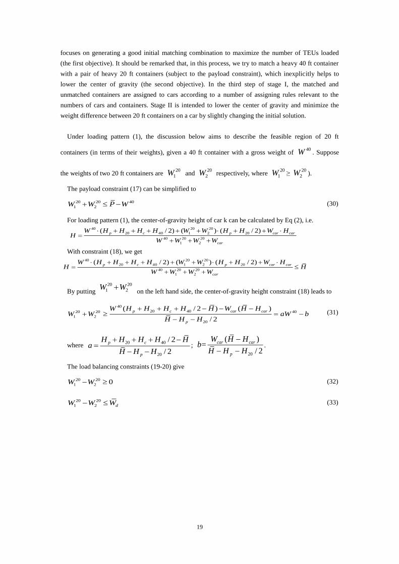
Under loading pattern (1), the discussion below aims to describe the feasible region of 20 ft
containers (in terms of their weights), given a 40 ft container with a gross weight of 40W . Suppose
the weights of two 20 ft containers are 20
1W and 20
2W respectively, where 20
1W ≥ 20
2W ).
The payload constraint (17) can be simplified to
20 20 40
1 2W W P W (30)
For loading pattern (1), the center-of-gravity height of car k can be calculated by Eq (2), i.e. 40 20 20
20 40 1 2 20
40 20 20
1 2
( / 2) ( ) ( / 2)
p c p car car
car
W H H H H W W H H W HH
W W W W
With constraint (18), we get
40 20 20
20 40 1 2 20
40 20 20
1 2
( / 2) ( ) ( / 2)
p c p car car
car
W H H H H W W H H W HH H
W W W W
By putting 20 20
1 2W W on the left hand side, the center-of-gravity height constraint (18) leads to
40
20 4020 20 40
1 2
20
( / 2 ) ( )
/ 2
p c car car
p
W H H H H H W H HW W aW b
H H H
(31)
where 20 40
20
/ 2
/ 2
p c
p
H H H H Ha
H H H
;
20
( )=
/ 2
car car
p
W H Hb
H H H
.
The load balancing constraints (19-20) give
20 20
1 2 0W W (32)
20 20
1 2 dW W W (33)

20
W220
W120
_
P-W40
_
Wd
aW40-b
_
P-W40
(1)
(2)
(3)
(4)
W40
W40
Figure 7. The feasible region of the weights of 20 ft containers which can be matched to a 40 ft
container with the weight of 40W under loading pattern (1)
In Figure 7, Lines (1), (2), (3) and (4) correspond to Equations 20 20 40
1 2W W P W ,
20 20 40
1 2 =a bW W W ,
20 20
1 2 0W W
and
20 20
1 2 dW W W
separately.
Figure 7 shows
that, when 40W increases, the line (1) moves toward the origin of the coordinate while the line (2)
leaves away from the origin of the coordinate, then the feasible region of matching 20 ft containers
(marked in the shaded area) shrinks accordingly. That is, the heavier a 40 ft container, the more difficult
it is to find matching 20 ft containers. Therefore, in the matching process, our algorithm gives the
priority for heavier 40 ft containers. Furthermore, when selecting the 20 ft container pair to be matched,
we should select heavy ones to lower the overall center of gravity of the loaded double-stack car,
subject to the payload constraints. This forms the basis for our sequential heuristic matching algorithm.
7.2. Matching 20 ft container pairs to 40 ft containers and assigning containers on cars
Some notations for the heuristic algorithm
N20
= total number of 20 ft container pairs;
n = index of 20 ft container pair index, n= 1, …, N20
;
Pair(n,1) = the No. of the first 20 ft container in the nth
pair;
Pair(n,2) = the No. of the second 20 ft container in the nth
pair;
M = total number of matching groups;
m = index of matching groups (a matching group is a combination of a 20 ft container pair
and a 40 ft container which can be loaded in one double-stack car), m=1, …, M;
Match(m,1) = the No. of the first 20 ft container in the mth
matching group;
Match(m,2) = the No. of the second 20 ft container in the mth
matching group;
Match(m,3) = the No. of the 40 ft container in the mth
matching group;

21
U20
= total number of unmatched 20 ft container pairs;
U40
= total number of unmatched 40 ft containers.
Step 0: Read input data as unordered 40 ft and 20 ft containers.
Step 1: Sorting
Sort 40 ft containers according to a descending order of their weights, i.e.,
40 40
1 1 1j jW W j J .
Sort 20 ft containers according to a descending order of their weights, i.e.,
20 20
1 1 1i iW W i I .
Step 2: Pairing
Pair 20 ft containers sequentially to generate Pair(n,1), Pair(n,2) for n = 1,…, N20
subject to load
balancing constraints ( 20 20
Pair(n,1) Pair(n,2) dW W W ).
Step 3: Matching
Match 20 ft container pairs with 40 ft containers sequentially to generate Match(m,1), Match(m,2),
Match(m,3) for m=1, …, M subject to payload constraints 20 20 40
Match(m,1) Match(m,2) Match(m,3)W W P W
and center-of-gravity height constraints 20 20 40
Match(m,1) Match(m,2) Match(m,3)W W aW b . If a 40 ft
container cannot find a pair of 20 ft containers to match, move it to the unmatched 40 ft container set.
If a 20 ft container pair is not matched by any 40 ft container, move it to the unmatched 20 ft container
pair set.
Step 4: Assigning
Assign matched groups, unmatched 20 ft container pairs and unmatched 40 ft containers being
placed on cars according to the different conditions described in the decision tree of Figure 8 and the
following decision rules. We will further discuss the typical cases for assigning containers on cars.
There are two mutually exclusive cases in terms of K as the number of cars and M as the number of the
matching groups of 20 ft containers and 40 ft containers.

22
Decision Tree
K>MK≤M
Rule AK≤M+U20+U40 K>M+U20+U40
Rule BK≤2M+U20+U40 K>2M+U20+U40
Rule C Rule D
Figure 8. Container-to-car assignment decision tree
Rule A: Out of M matched groups of containers, select the K groups with the lowest loaded
center-of-gravities to K cars separately. The loaded center-of-gravity of a matching group refers to the
center of gravity of the car loaded with the matching group of containers.
Rule B: Assign M matched groups of containers to M out of K cars separately; select (K-M) out of
U20
unmatched 20 ft container pairs and U40
unmatched 40 ft containers to load on (K-M) cars
separately.
Rule C: Assign U20
unmatched 20 ft container pairs to U20
cars separately; assign U40
unmatched 40
ft containers to U40
cars separately; select (K-M-U20
-U40
) out of M matched groups of containers with
the highest loaded center-of-gravities, and assign them to 2×(K-M-U20
-U40
) cars, i.e., for each group of
containers, assign the two 20 ft containers to one car and the 40 ft container to another car; assign
(2M+U20
+U40
-K) unsplit matching groups of containers to (2M+ U20
+ U40
-K) cars.
Rule D: Assign U20
unmatched 20 ft container pairs to U20
cars separately; assign U40
unmatched 40
ft containers to U40
cars separately; assign M matched groups of containers to 2M cars, i.e., for each
matched group of containers, assign the two 20 ft containers to one car and the 40 ft container to
another car.
If K≤M, then there are enough TEUs from matched containers (for the first objective). Thus, we
focus on the second objective, and assign the matching groups with lower loaded center-of-gravities.
This leads to Rule A. Otherwise (i.e. K>M), then there are K-M cars left for unmatched containers. To
increase the total TEUs loaded, we need to assign as many unmatched containers as possible to cars
(using Rules B). In particular, in the case of K>(M+U20
+U40
), there are sufficient TEUs (from matched
and unmatched containers) and the first objective cannot be further improved. As a result, we focus on
the second objective by splitting some matching groups with higher loaded center-of-gravities. This
leads to Rules C and D.
7.3. Improving solution
Based on an initial solution to the double-stack car loading problem, the second stage is designed to
improve its solution quality by changing containers’ positions. The following improvement algorithm is
carried out for a certain number of iterations.
Step 1: From the current candidate solution, randomly and simultaneously select two 20 ft containers

23
and two 40 ft containers from all containers.
Step 2: Construct a neighbor solution by exchanging the positions of the two 20 ft containers and
exchanging the positions of the two 40 ft containers. If this new neighbor solution is better than the
candidate solution, then the current solution is replaced by this neighbor solution.
Note that containers staying on cars and being unloaded can be selected in this local search process.
In our experiments, the number of iterations is set as 2I2 to permit sufficient solution coverage.
In the following illustrative example, the weights of nine 20 ft containers and four 40 ft containers
are shown in Table 2 and Table 3, respectively.
Table 2. Weights of 20 ft containers.
20 ft container No. 1 2 3 4 5 6 7 8 9
Weight (tons) 30.0 28.2 26.8 25.5 24.1 13.0 10.6 8.7 6.3
Table 3. Weights of 40 ft containers.
40 ft container No. 1 2 3 4
Weight (tons) 30.2 26.6 20.7 15.3
The pairing algorithm from Stage I generate 20 ft container pairs shown in Table 4. Note that, 20 ft
container No.5 is not paired, because the weight difference between containers No.5 and No.6 does not
meet the load balancing constraint.
Table 4. 20 ft container pairs.
20 ft container pair No. 1 2 3 4
20 ft container No. 1, 2 3, 4 6, 7 8, 9
Shown in Table 5, the matching algorithm produces the following matching groups. There are four
unmatched containers. Specifically, 40 ft container No. 1 is unmatched because it is too heavy to match
with a 20 ft container pair subject to the payload constraint and the center-of-gravity height constraint.
20 ft container pair (8,9) is unmatched as there are not enough 40 ft containers to be matched. Recall
that, 20 ft container No. 5 is left from the pairing process.
Table 5. Matching groups.
Group No. 40 ft container No. 20 ft container No.
1 2 6, 7
2 3 3, 4
3 4 1, 2
The assignment algorithm constructs car loading plans under different numbers of available cars,
shown in Table 6.
Table 6. Loading plans under different number of available cars.
K=3 K =4 K =5 K =7 K =9
Car
No.
20’
No.
40’
No.
Car
No.
20’
No.
40’
No.
Car
No.
20’
No.
40’
No.
Car
No.
20’
No.
40’
No.
Car
No.
20’
No.
40’
No.

24
1 1, 2 4 1 6, 7 2 1 6, 7 2 1 8, 9 -- 1 8, 9 --
2 3, 4 3 2 3, 4 3 2 3, 4 3 2 -- 1 2 -- 1
3 6, 7 2 3 1, 2 4 3 1, 2 4 3 6, 7 -- 3 6, 7 --
4 8, 9 -- 4 8, 9 -- 4 -- 2 4 -- 2
5 -- 1 5 3, 4 -- 5 3, 4 --
6 -- 3 6 -- 3
7 1, 2 4 7 1, 2 --
8 -- 4
9 -- --
For the initial solution under K=3 in Table 6, using the solution improvement algorithm, we can find
an improved solution shown in Table 7. Specifically, the total TEUs loaded remain unchanged, but the
center-of-gravity height decreases from 2,322.26 mm to 2,141.01 mm.
Table 7. Loading plan of an improved solution.
Car No. 20 ft container No. 40 ft container No.
1 1, 2 4
2 6, 7 3
3 3, 5 2
8. Computational experiments
To demonstrate the proposed lexicographic goal programming approach, the tabu search algorithm,
and the two-stage heuristic algorithm for the double-stack car loading problem, we conduct
computational experiments on a PC with a 2.0 GHz CPU and a 2 GB RAM.
First, two small-scale problems are used to compare the results of the three approaches. In the first
example, five 40 ft containers and twelve 20 ft containers are to be loaded on five cars. In the second
example, twelve 40 ft containers and twenty 20 ft containers are to be loaded on ten cars. The weights
of the containers are randomly generated according to real-world container weight distributions. The
optimal and heuristic solutions can be obtained using the lexicographic goal programming approach
with GAMS (see Rosenthal (2008)) and the heuristic algorithm. The length of tabu list is set as 5 to
solve the two examples. Table 8 compares the results of the three approaches, and Wdmax stands for the
maximal weight difference of two 20 ft containers (in a single car) across all cars.

25
Table 8. The comparison of the results of three approaches.
Approach
Example 1 Example 2
TEUs Hmax
(mm)
Wdmax
(tons)
CPU
Time
(s)
TEUs Hmax
(mm)
Wdmax
(tons)
CPU
Time
(s)
Lexicographic
Goal
Programming
Approach
Step1 20 — — 0.523 40 — — 1.836
Step 2 20 2226.4 — 771 40 2182.5 — 7948
Step 3 20 2226.4 3.71 29.78 40 2182.5 3.59 1010
Total 20 2226.4 3.71 801 40 2182.5 3.59 8960
Tabu Search Algorithm 20 2226.4 3.71 0.015 40 2182.5 3.59 1.0
Two-Stage Heuristic
Algorithm 20 2226.4 3.71 0.007 40 2182.5 3.59 0.015
In the lexicographic goal programming approach, the optimal center-of-gravity height is obtained by
solving iterative mixed integer linear programming problems using the COINCBC solver. Figure 9
further details the iterative process of using the bisection algorithm in solving the first example, where
the termination condition error bound ε is set to 1 mm.
Figure 9. Iterative process of bisection algorithm
Table 8 indicates that, all of the three solution approaches obtain the same optimal solutions for these
two examples. The lexicographic goal programming approach takes about 13 min to 2.5 hours, which is
very time consuming compared to the two heuristic algorithms, even for small-scale instances. The
optimization approach fails to solve a real-world instance with up to 300 containers and 100
double-stack cars within reasonable computing time limits. However, it is important to recognize the
significance of the proposed optimization algorithms, since an optimal solution not only provides a
yardstick for systematically evaluating ad-hoc heuristic algorithms but also generates an exact upper
bound on the total operational cost savings attainable with alternative system design/improvement
scenarios.
Table 8 also indicates that, the tabu search algorithm is less efficient than the two-stage heuristics
algorithm for solving the small-scale double-stack car loading problems. To compare the computational

26
performance of the two proposed heuristic algorithms in real-world cases, we collected the real weights
of 20 ft containers and 40 ft containers transported from Dahongmeng Station in Beijing to Yangpu
Station in Shanghai. By using these data, we designed the following eight real-world cases.
(1) 240 20 ft containers, 100 40 ft containers, 100 cars;
(2) 240 20 ft containers, 100 40 ft containers, 90 cars;
(3) 240 20 ft containers, 100 40 ft containers, 110 cars;
(4) 240 20 ft containers, 100 40 ft containers, 130 cars;
(5) 160 20 ft containers, 100 40 ft containers, 80 cars;
(6) 160 20 ft containers, 100 40 ft containers, 70 cars;
(7) 160 20 ft containers, 100 40 ft containers, 90 cars;
(8) 160 20 ft containers, 100 40 ft containers,110 cars.
The results of the two heuristic algorithms for solving the above eight cases are listed in Table 9. The
length of tabu list is set as 10 to solve these eight cases.
Table 9. The results of the two heuristic algorithms for real-world cases.
Case
No.
Two-Stage Heuristic Algorithm Tabu Search Algorithm
TEUs Hmax
(mm)
Wdmax
(tons)
CPU
time (s)
TEUs Hmax
(mm)
Wdmax
(tons)
CPU
time (s)
(1) 400 2209.04 8.44 4.31 400 2209.54 9.94 9.08
(2) 360 2189.00 7.54 4.26 360 2189.70 9.84 8.45
(3) 420 2209.04 8.44 4.97 420 2209.64 9.98 9.55
(4) 440 2189.12 8.74 5.56 440 2209.44 10.00 10.4
(5) 320 2179.69 5.84 1.5 320 2187.14 9.92 3.11
(6) 280 2150.72 9.40 2.11 280 2159.91 9.54 2.81
(7) 340 2179.69 5.84 1.67 340 2192.56 9.78 3.23
(8) 360 2150.72 7.50 1.82 360 2190.11 9.92 3.58
Table 9 indicates that both of the two heuristic algorithms can obtain the close-to-optimal solutions
of real-world double-stack car loading problems. Compared to tabu search algorithm, the two-stage
heuristic algorithm can get better solutions in less computation times. So the two-stage heuristic
algorithm is more effective and efficient than the tabu search algorithm in solving real-world
double-stack car loading problems.
9. Conclusions
This paper presents a multi-objective model for the double-stack car loading problem, which
specifically takes into account the operational productivity and safety concerns of the double-stack
train service. A three-step lexicographic goal programming approach is designed to handle three
objectives with different priorities. As the center-of-gravity height optimization problem is a
generalized mixed integer linear-fractional programming problem, it is reformulated and further solved
by a bisection algorithm. In summary, this research develops a systematic optimization solution
procedure for the double-stack car loading problem, which has been further implemented and tested
using the optimization software package GAMS.

27
To solve the real-world large-scale instances efficiently, a tabu search algorithm and a rule-based
two-stage heuristic algorithm was designed. The tabu search algorithm is designed to generate an initial
solution randomly and to improve the solutions by using 2-opt and tabu list techniques. The two-stage
heuristic algorithm is designed to perform pairing, matching, assignment steps so as to rapidly
construct an initial loading plan that satisfies a large number of constraints. At each step, the priority of
different objectives is dynamically adjusted based on the given input and intermediate solution results.
A local search algorithm is further used to improve the final solution quality. Both optimization and
heuristic approaches are tested on two small-scale instances, and the two heuristic approaches can
obtain the same optimal solutions while taking reasonable computational resources. The computational
performance of the two proposed heuristic algorithm is also demonstrated by using several real-world
cases. The results indicate that the two-stage heuristic algorithm is more effective and efficient than the
tabu search algorithm in solving real-world double-stack car loading problems.
The future study will further take into account the destinations of the containers and the trains so that
containers can be handled efficiently at following container transfer terminates. The priority of
containers should also be addressed in the optimization process to meet shippers’ requirements. In
addition, alternative heuristics can be designed to take advantage of problem-specific characteristics in
the double-stack car loading problem.
Acknowledgements
This research of the first author was supported by China Scholarship Council, and project No.
60870014 funded by National Natural Science Foundation of China and project No. 2006BAJ07b03
funded by the Ministry of Science and Technology of the People’s Republic of China. The authors are
of course responsible for all results and opinions expressed in this paper.
References
Anderson, E., Haggstrom, J., Sima, M., Stichel, S., 2004. Assessment of train-overturning risk due to
strong cross-winds. Proceedings of the Institution of Mechanical Engineers, Part F: Journal of Rail and
Rapid Transit 218: 213, 213-223.
Andersson, E., and Berg, M., 2001. Railway Systems and Rail Vehicles, Course Book, Part 2, Section
13.1.8, Kunglliga Tekniska Hogskolan Railway Technology, Stockholm.
―APTA‖ American Public Transit Association Commuter Rail Executive Committee, 2007. APTA
SS-M-015-06 Standard for Wheel Flange Angle for Passenger Equipment. The American Public
Transportation Association, Washington, D.C.
―AREMA‖ The American Railway Engineering and Maintenance-of-Way Association, 2003. Practical
Guide to Railway Engineering. Chapter 6, Railway Track Design, Lanham, MD.
―BNSF‖ Burlington Northern Santa Fe Railway, 2005. BNSF Intermodal Loading Guide: Loading
Double Stack. Ft. Worth, TX.

28
Brandbury, W. M. S., Pottrill, P., Murtagh, V., 2003. Enhanced permissible speed on the West Coast
mainline: investigations of wind overturning effects. In Proceedings of the 6th
World Congress on
Railway Research, Edinburgh, 476-485.
Cleon, L, M., and Jourdain, A., 2001. Protection of line LN5 against cross winds. In Proceedings of
the 5th
World Congress on Railway Research, Koln, Germany.
Dukkipati, R. V., and Amyot, J. R.,1988. Computer-aided simulation in railway dynamics. New York,
NY. Marcel Dekker, Inc.
Freight Car America, Inc., 2011. The BethGon Aeroflo. Retrieved from
http://www.freightcaramerica.com/aluminum-bethgon-aeroflo.htm.
Fujii, T., Maeda, T., Ishida, H., Imai, T., Tanemoto, K., Suzuki, M., 1999. Wind-induced accidents of
trains/vehicles and their measures in Japan. Q. Rep. RTRI, 40(1), 50-55.
Gautier, P. E., Tielkes, T., Sourget, F., Allain, E., Grab, M., Heine, C., 2003. Strong wind risks in
railways: the DEUFRAKO crosswind program. In Proceedings of the 6th
World Congress on Railway
Research, Edinburgh, 476-485.
Gawthorpe, R. G., 1994. Wind effects on ground transportation. J. Wind Engng Ind. Aerodynamics, 52,
73-92.
Holowaty, M. C., Cogswell, R. U., Moyer, N. E., 2004. Technical Monograph: Transportation Planning
for the Richmond-Charlotte Railroad Corridor. Federal Railroad Administration US Department of
Transportation, Washington, D.C. Volume II.
Ichoua, S., Gendreau, M., Potvin, J. Y., 2003. Vehicle dispatching with time-dependent travel times.
European Journal of Operational Research 144(2), 379–396.
Imai, A., Sasaki,K., Nishimura, E., Papadimitriou, S., 2006. Multi-objective simultaneous stowage and
load planning for a container ship with container rehandle in yard stacks. European Journal of
Operational Research 171(2), 373-389.
Jahren, C. T. and Rolle, S. S., 1994. A computerized assignment algorithm for loading intermodal
containers to double-stack railcars. Final report. University of Washington.
Jahren, C. T. and Rolle, S. S., Spurgeon, L. E., Palmer, R. N., Newman, R. R., Howland, D. L.,
1995. Automatic assignment algorithms for loading double-stack railcars. Transportation Research
Record 1511, 10-18.
Lippert, S., 1999. On Side Wind Stability of Trains, Kungliga Tekniska Hogskolan Railway Technology,
Stockholm.
29
Lippert, S., Tengstrand, H., Andersson, E., Stichel, S., 2000. The effect of strong cross winds on rail
vehicles. VDI Ber., 1586, 221.
Loumiet, J. R. and Jungbauer, W. G., 2005. Train Accident Reconstruction and FELA and Railroad
Litigation. Tucson, Az. Lawyers and Judges Publishing Company, Inc.
Mancini, G., Cheli, R., Roberti, R., Diana, G., Cheli, F., Tomasini, G., Corradi, R., 2003. Cross-wind
aerodynamic forces on rail vehicles – wind tunnel experimental tests and numerical dynamic analysis.
In Proceedings of the 6th
World Congress on Railway Research, Edinburgh, 513-522.
Matschke, G., Tilkes, T., Deeg, P., Schulte-Werning, B., Locher, P., Fermaud, C., Bohnenblust, H. ,
2000. Effects of strong cross winds on high-speed trains – a risk assessment approach. In Proceedings
of the International Conference on Probabilistic Safety Assessment and Management, Osaka, Japan.
Mongeau, M. and Bes, C., 2003. Optimization of aircraft container loading, IEEE Transactions on
Aerospace and Electronic Systems, 39(1), 140-150.
Norfolk Southern, 1999. Norfolk Southern Intermodal Operations Manual: Loading and Securement:
Stack Cars., Norfolk, VA.
Pacanovsky, D. L., Jahren, C. T., Palmer, R. N., Newman, R. R., and Howland, D., 1995. A decision
support system to load containers to double-stack rail cars. Civil Engineering and Environmental
Systems 11(4), 247-261.
Raidl, G. R., Kodydek, G., 1998. Genetic algorithms for the multiple container packing problem.
Lecture Notes in Computer Science 1498, 875-884.
―RGS‖ Railway Group Standard GM/RT 2142., 1994. Resistance of Railway Vehicles to Overturning
in Gales, Issue One, Safety and Standard Directorate Railtrack, Great Brittan.
Rosenthal, R. E., 2008. GAMS user’s guide, GAMS Development Corporation, Washington, DC, USA.
Schulte-Werning, B. and Matschke, G., 1997. Measures and strategies to minimize the effect of strong
cross-winds on high-speed trains. In Proceedings of the 3rd
Words Congress on Railway Research,
Florence, Italy, E, 569-575.
Soak, S. M., Lee, S. W., Yeo, G. T., Jeon, M. G., 2008. An effective evolutionary algorithm for the
multiple container packing problem. Progress in Natural Science 18(3), 337-344.
Talgo Inc., 2011. Talgo Technological Principals. Available from
http://www.talgoamerica.com/pdf/Talgo-Technological-Principals-Brochure.pdf [Accessed 1 May
2011]
Tamiz, M., Jones, D., Romero, C., 1998. Goal programming for decision making: An overview of the

30
current state-of-the-art. European Journal of Operational Research 111(3), 569-581.
Union Pacific Railroad., 2010. Intermodal Reports Database: Intermodal Ramp Policy Load Planning.
Omaha, NE.
―USDOT-FRA‖ U.S. Department of Transportation Federal Railroad Administration., 2002. Track
Safety Standards Compliance Manual. Department of Transportation Office of Safety Assurance and
Compliance, Washington D.C.
―USDOT-FRA‖ U.S. Department of Transportation Federal Railroad Administration., 2005. Safe
Placement of Train Cars: A Report. Report to the Senate Committee on Commerce, Science and
Transportation and the House Committee on Transportation and Infrastructure, Washington D.C.
―USDOT-FRA‖ U.S. Department of Transportation Federal Railroad Administration., 2011. Track
Safety Standards, Final Rule. 49 CFR Part 213 Department of Transportation, Washington, D.C.

![Ranking Decision making units using Fuzzy Multi-Objective ......Multi-objective Linear Programming (MOLP) Veeramani et al. [23] Multi-objective Linear Programming (MOLP) Problems is](https://img.pdfslide.us/doc/110x75/610e91b630eca77d674f86aa/ranking-decision-making-units-using-fuzzy-multi-objective-multi-objective.jpg)

![Research on Key Problems of Multi-objective …...suitable for solving multi-objective optimization problems, and from the birth of the multi-objective evolutionary algorithm [4]](https://img.pdfslide.us/doc/110x75/5fdea634eea5627aa25b2fca/research-on-key-problems-of-multi-objective-suitable-for-solving-multi-objective.jpg)