Embed Size (px)
Citation preview

Page 1
Double 4K Multispectral
Pix4D User Guide
Rev G
November 29, 2019

Page 2
Contents
OVERVIEW 3
REQUIREMENTS 3
PROCESSING INSTRUCTIONS 7
INSERTING GROUND CONTROL POINTS 19
REFLECTANCE AND NDVI CALCUATIONS 20
APPENDIX A - LARGE DATA SETS 27
APPENDIX B - STITCHING FAILS 28
APPENDIX C - SAVING TEMPLATES 29
APPENDIX D – CREATING A 5 BAND SINGLE GEOTIFF 30
APPENDIX G – IMPORT A 5 BAND SINGLE GEOTIFF INTO FIELDAGENT 34

Page 3
OVERVIEW
Sentera has optimized settings and a workflow for stitching Sentera Double 4K imagery with Pix4D.
While Sentera does not officially support Pix4D, this guide offers a starting point for customers
interested in using Pix4D with Sentera imagery. This guide is specifically for producing stitched mosaics
from images taken by Sentera’s Double 4K multispectral imager. FieldAgent can be used to create RGB,
NDVI and NDRE images without mosaicing.
REQUIREMENTS
Pix4D, like all stitching software, performs better with high overlap. Sentera recommends a minimum of
70% overlap for Pix4D. Sentera has stitched with 65% and 60% in in ideal conditions but finds 70% to
provide good results consistently.
Table 1 - Camera parameters for the Double 4K camera.
Focal Length 5.4 mm
Pixel Pitch 1.55 um
Resolution 4000x3000 pixels
Sensor Width 6.200 mm
Sensor Height 4.640 mm
Page 4
PREPROCESSING
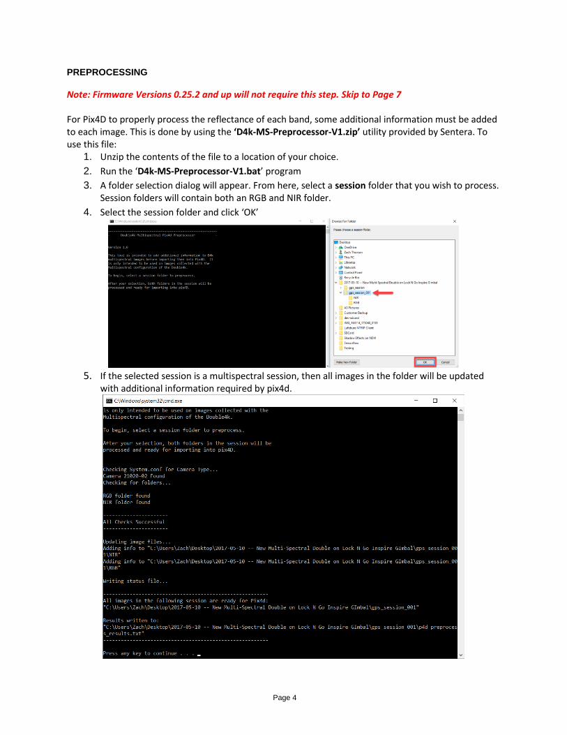
Note: Firmware Versions 0.25.2 and up will not require this step. Skip to Page 7 For Pix4D to properly process the reflectance of each band, some additional information must be added to each image. This is done by using the ‘D4k-MS-Preprocessor-V1.zip’ utility provided by Sentera. To use this file:
1. Unzip the contents of the file to a location of your choice.
2. Run the ‘D4k-MS-Preprocessor-V1.bat’ program
3. A folder selection dialog will appear. From here, select a session folder that you wish to process. Session folders will contain both an RGB and NIR folder.
4. Select the session folder and click ‘OK’
5. If the selected session is a multispectral session, then all images in the folder will be updated
with additional information required by pix4d.
Page 5
6. On success, a new file in the session will be created called ‘p4d_preprocess_results.txt’. The presence of this file should act as an indicator that the correct XMP tags have been added to this session.
7. Run this script on all sessions that you wish to use in Pix4D.
PREPARING PIX4D FOR THE NEW PROCESS
IMPORTANT: This step is only required if you have used the multispectral camera for stitching projects in the past. You will only have to do this once to convert over to the new Multispectral process. After this, you can skip this step. Pix4D will attempt to remember any cameras and settings that you have use in previous stitching projects. As a side effect of this, it will end up ignoring the new changes to the files that allow for easier multispectral camera usage. To force Pix4D to load all the camera parameters and bands from the images instead of it’s database, you have to delete the old entries from the internal database. Perform the following steps to do this:
1. Close any open copies of Pix4D
2. Navigate to the pix4d database at:
a. C:\Users\<Your UserName>\AppData\Local\pix4d\common\<pix4d Version #>\
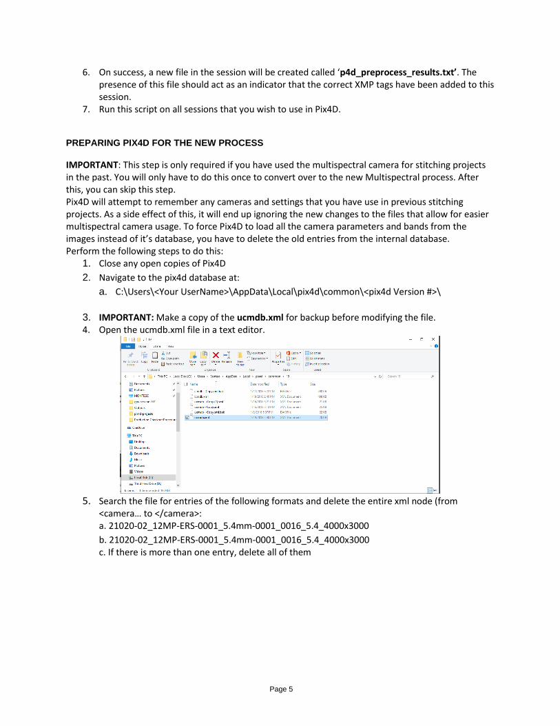
3. IMPORTANT: Make a copy of the ucmdb.xml for backup before modifying the file. 4. Open the ucmdb.xml file in a text editor.
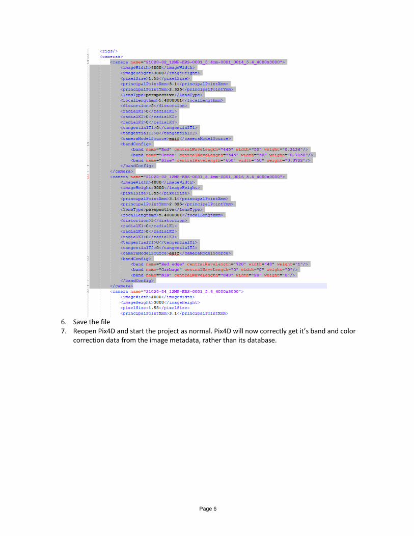
5. Search the file for entries of the following formats and delete the entire xml node (from
<camera… to </camera>: a. 21020-02_12MP-ERS-0001_5.4mm-0001_0016_5.4_4000x3000
b. 21020-02_12MP-ERS-0001_5.4mm-0001_0016_5.4_4000x3000 c. If there is more than one entry, delete all of them
Page 6
6. Save the file 7. Reopen Pix4D and start the project as normal. Pix4D will now correctly get it’s band and color
correction data from the image metadata, rather than its database.
Page 7
PROCESSING INSTRUCTIONS
1. Launch Pix4Dmapper
2. Create a new project.
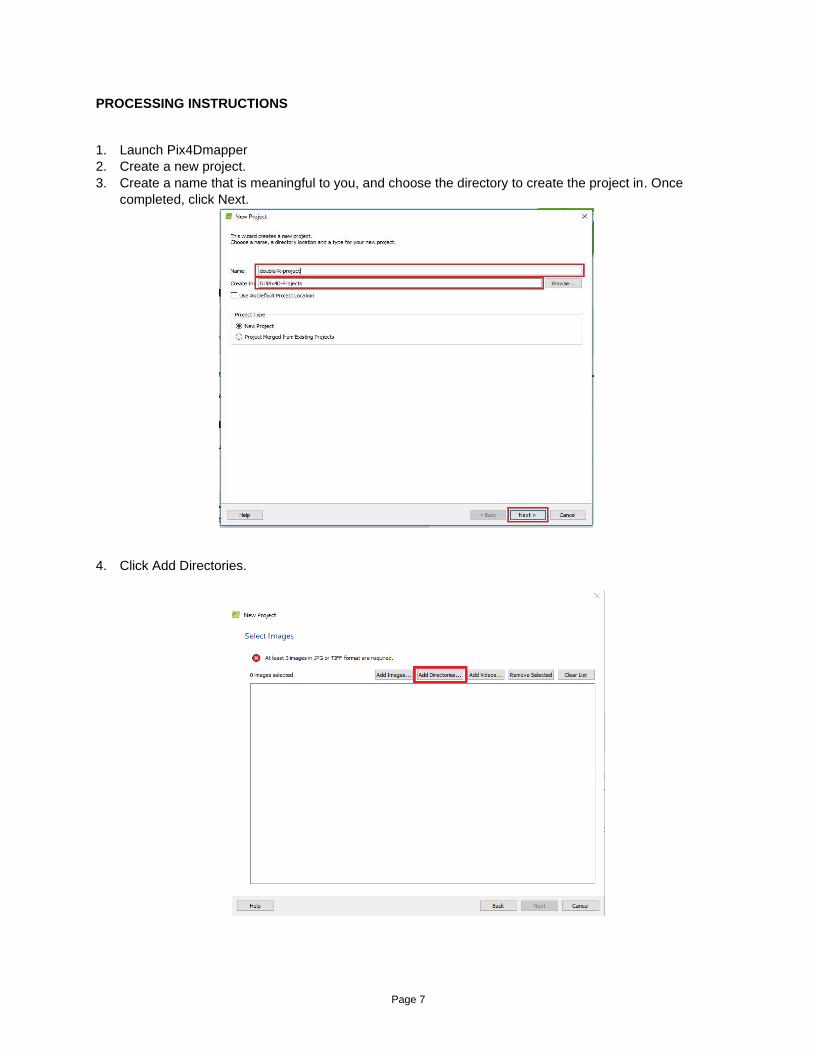
3. Create a name that is meaningful to you, and choose the directory to create the project in. Once
completed, click Next.
4. Click Add Directories.
Page 8
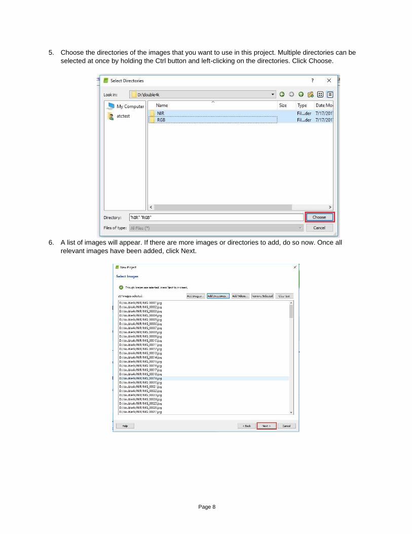
5. Choose the directories of the images that you want to use in this project. Multiple directories can be
selected at once by holding the Ctrl button and left-clicking on the directories. Click Choose.
6. A list of images will appear. If there are more images or directories to add, do so now. Once all
relevant images have been added, click Next.

Page 9
Note: Step 7 to 10 only needs to be done one time and only if you have never done it before.
Otherwise skip to Step 11
7. The images will appear in a list on the next page with information about the camera models. First, we
will ensure that the camera model parameters that Pix4D automatically determines are correct. For
each camera model, click Edit.
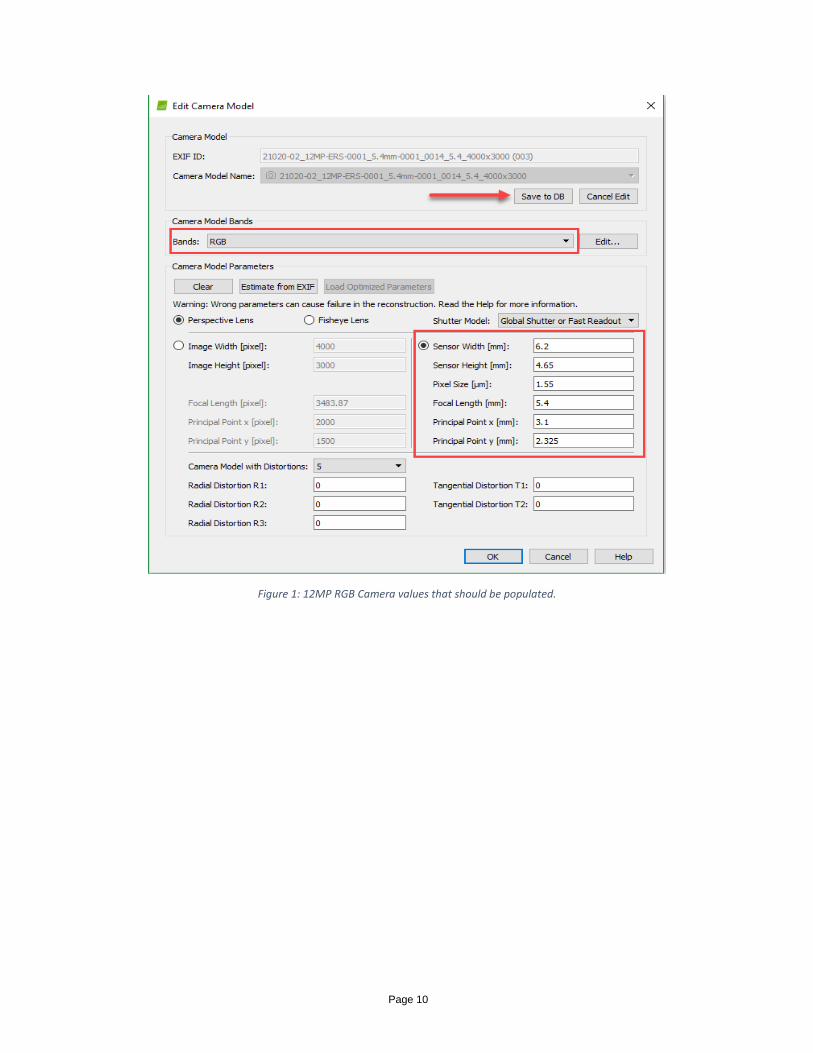
8. If the camera values look incorrect, select ‘Edit’ to edit the parameters. The parameters should match
those in the figures below. These values apply only to the Double 4K camera. When finished,
select “Save to DB” to use these values in the future.
Imagers with recent firmware updates will auto-populate the pixel size and focal length in the Pix4D
lens model, but it’s important to verify they are populated correctly, since they will not override any
camera models previously saved to the Pix4D camera model database.
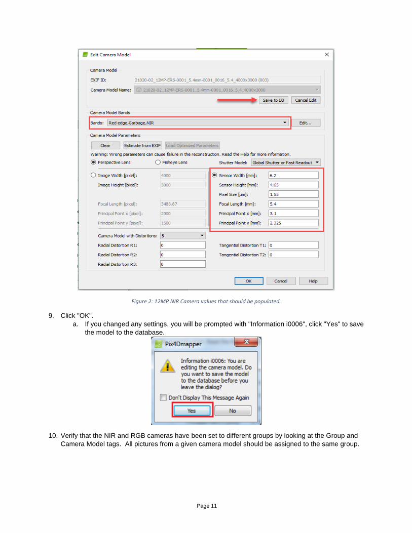
Double check the RGB Camera (0014) uses bands RGB, and the NIR Camera (0016) uses bands
Red edge, Garbage, NIR and that all other settings are correct.
Page 10
Figure 1: 12MP RGB Camera values that should be populated.
Page 11
Figure 2: 12MP NIR Camera values that should be populated.
9. Click "OK".
a. If you changed any settings, you will be prompted with "Information i0006", click "Yes" to save
the model to the database.
10. Verify that the NIR and RGB cameras have been set to different groups by looking at the Group and
Camera Model tags. All pictures from a given camera model should be assigned to the same group.

Page 12
11. Click Next and click Next on the Select Output Coordinate System menu.
12. On the Processing Options Template menu, if the Sentera Double4K Multispectral V6 template is not
listed in the menu yet, choose any template. All settings will be overridden in the next few steps.
Otherwise, choose the “Sentera Double4k Multispectral V6” template. Click Finish.
13. Now the project should be open. If you already loaded the Sentera Double 4K Multispectral V4
template in the previous step, skip to Step 21. Otherwise, click on Processing Options.
Page 13
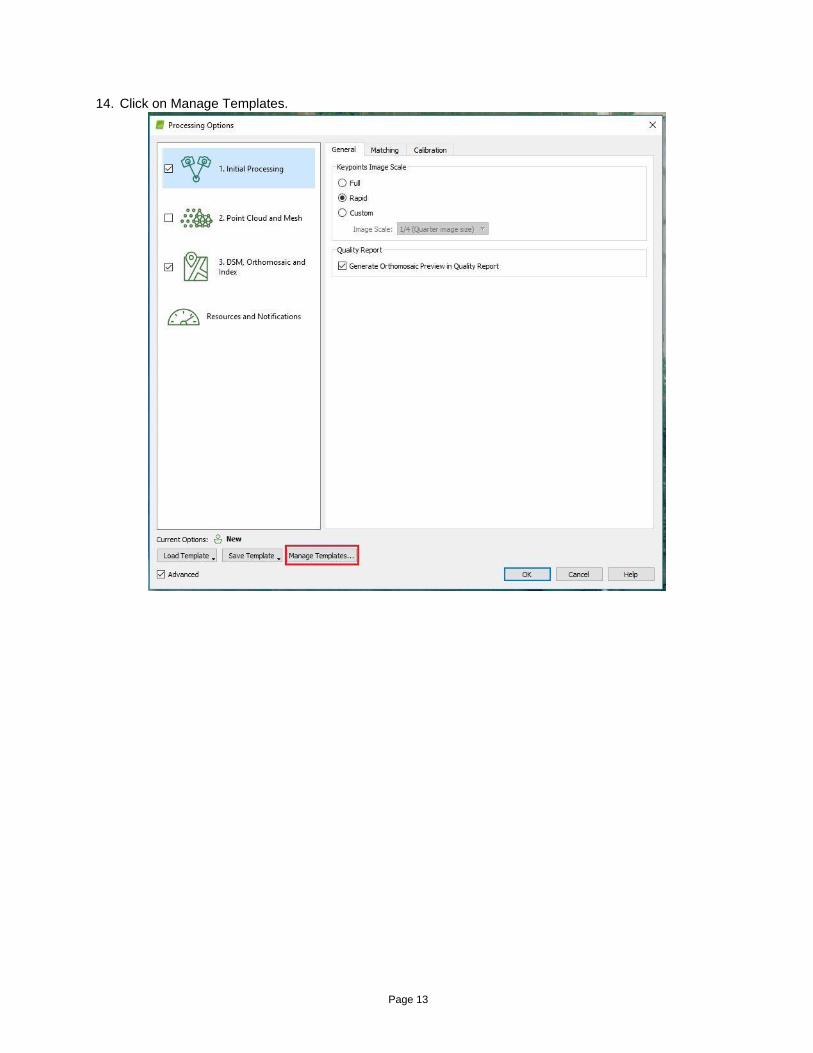
14. Click on Manage Templates.
Page 14
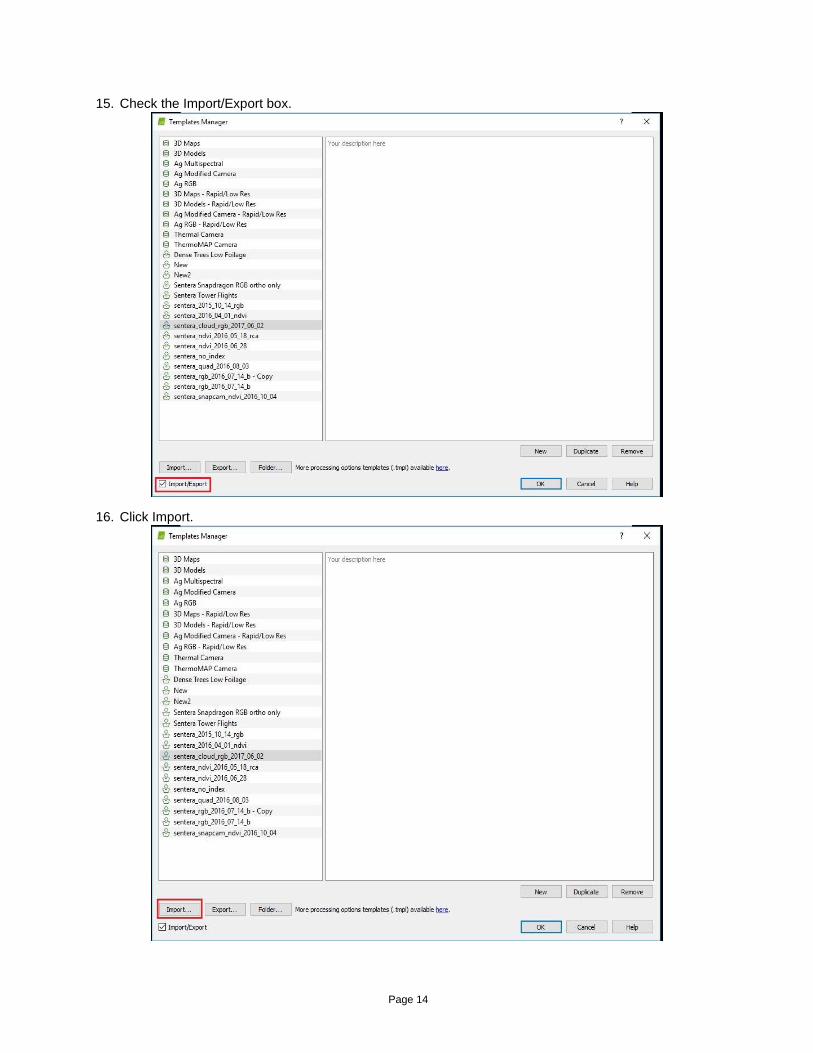
15. Check the Import/Export box.
16. Click Import.
Page 15
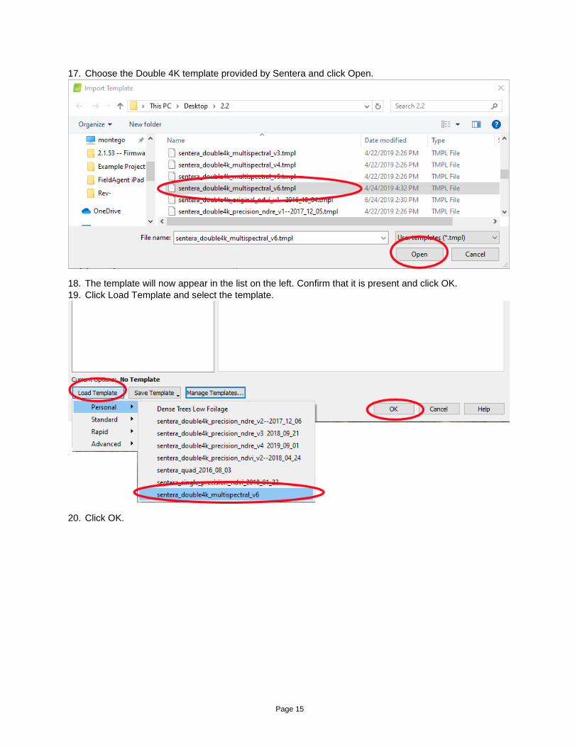
17. Choose the Double 4K template provided by Sentera and click Open.
18. The template will now appear in the list on the left. Confirm that it is present and click OK.
19. Click Load Template and select the template.
20. Click OK.
Page 16
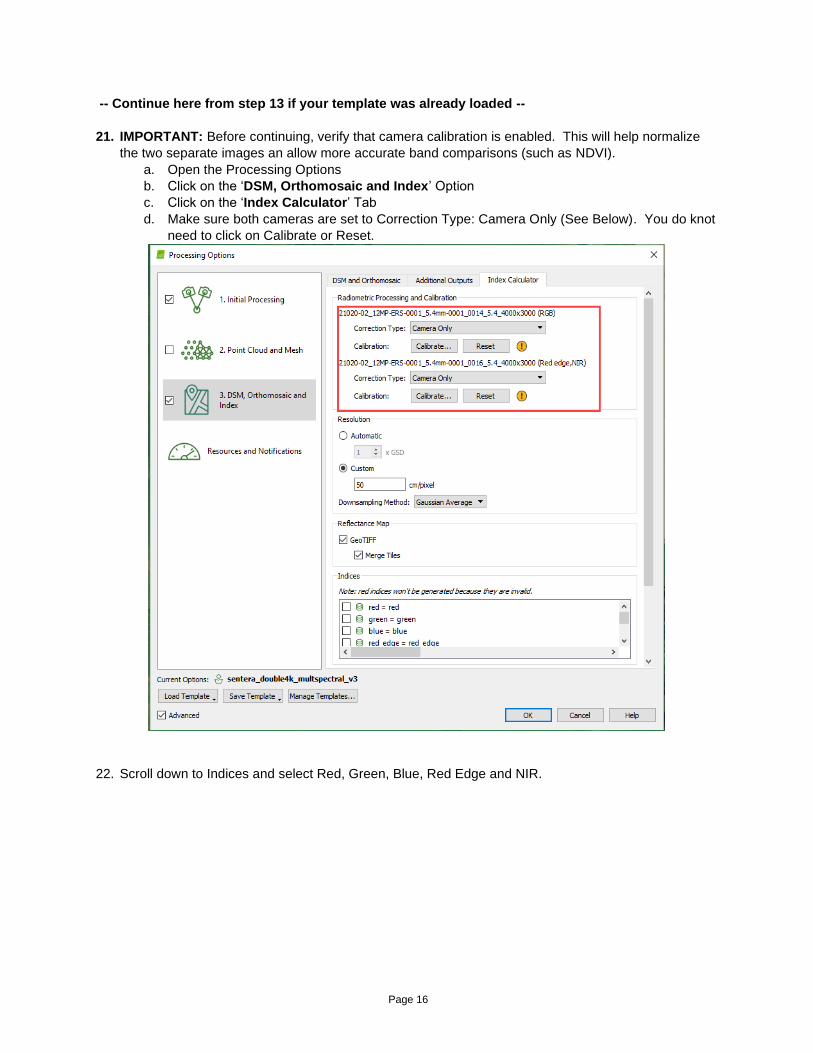
-- Continue here from step 13 if your template was already loaded --
21. IMPORTANT: Before continuing, verify that camera calibration is enabled. This will help normalize
the two separate images an allow more accurate band comparisons (such as NDVI).
a. Open the Processing Options
b. Click on the ‘DSM, Orthomosaic and Index’ Option
c. Click on the ‘Index Calculator’ Tab
d. Make sure both cameras are set to Correction Type: Camera Only (See Below). You do knot
need to click on Calibrate or Reset.
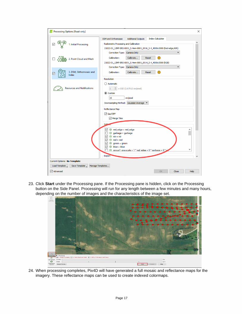
22. Scroll down to Indices and select Red, Green, Blue, Red Edge and NIR.
Page 17
23. Click Start under the Processing pane. If the Processing pane is hidden, click on the Processing
button on the Side Panel. Processing will run for any length between a few minutes and many hours,
depending on the number of images and the characteristics of the image set.
24. When processing completes, Pix4D will have generated a full mosaic and reflectance maps for the
imagery. These reflectance maps can be used to create indexed colormaps.

Page 18

Page 19
INSERTING GROUND CONTROL POINTS
1. Click on the Project Menu and select GCP/MTP Manager.
2. Set the GCP Coordinate System to match the GPC data. This can be Latitude/Longitude, Meters
or Feet.
3. Click on the “Add Point” button.
4. For each GCP change the “Type” value to 2D GCP
5. For the “X” value type in the value that is in Latitude/Longitude, Meters or Feet.
a. Value is determined by the GCP Coordinate System.
6. For the “Y” value type in the value that is in Latitude/Longitude, Meters or Feet.
a. Value is determined by the GCP Coordinate System.
7. Repeat steps 5 and 6 for each GPC. There should be a minimum of 5-8 per project.
8. Once the GCP are added. Click on the “OK” button to ensure they are in the correct spots.
9. Pix4D will place a Blue “X” for each GCP.
10. Run and complete Processing Step 1, unselect Step 2 and 3. Let Step 1 complete.

Page 20
11. Click on the Project Menu and select GCP/MTP Manager
12. Click on the “Basic Editor” button at the bottom of the dialog box.
13. Select Sort Images by Distance to GCP.
14. On the “Image” section select the image and zoom in and mark the GPC.
15. Repeat step 13 for at least 3 to 8 images. Marking the same spot each time.
16. Select another GCP from the GCP/MTP Table and repeat steps 13 and 14 until all of the GCP
have been completed.
17. Click on the “OK” button at the bottom of the dialog box.
18. Click on the Process Menu and select “Reoptimize”
19. Click on the “OK” button let the process run and complete.
20. Run and complete Processing step 3. Ensure the Processing Step 1 is unchecked.
REFLECTANCE AND NDVI CALCUATIONS
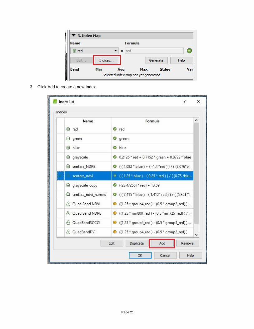
1. Click on Index Calculator.
2. Check to see if the NDVI and NDRE indices are present in the dropdown. If one more of these are
missing, click Indices… and continue to Step 3. If there are NDVI or NDRE indices present, skip to
Step 6.
Page 21
3. Click Add to create a new Index.
Page 22
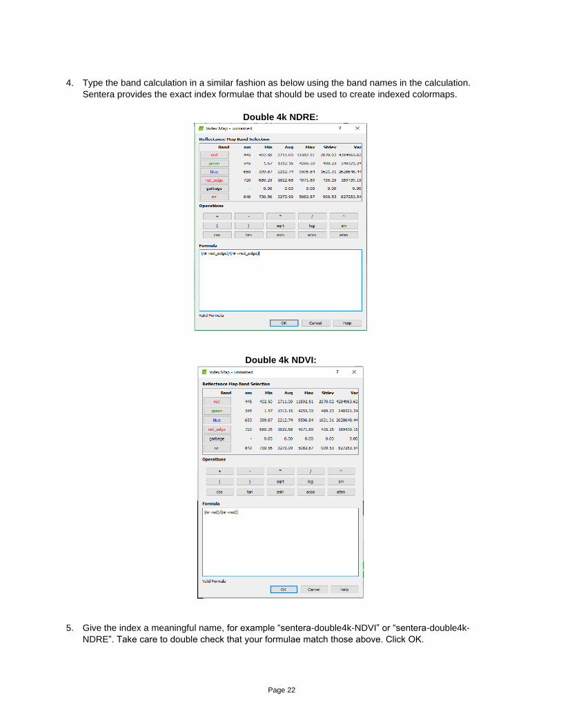
4. Type the band calculation in a similar fashion as below using the band names in the calculation.
Sentera provides the exact index formulae that should be used to create indexed colormaps.
Double 4k NDRE:
Double 4k NDVI:
5. Give the index a meaningful name, for example “sentera-double4k-NDVI” or “sentera-double4k-
NDRE”. Take care to double check that your formulae match those above. Click OK.
Page 23
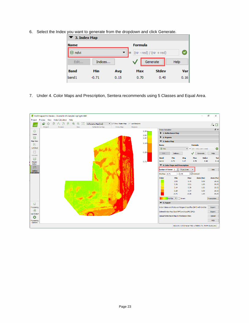
6. Select the Index you want to generate from the dropdown and click Generate.
7. Under 4. Color Maps and Prescription, Sentera recommends using 5 Classes and Equal Area.

Page 24
8. Under 5. Export, click the second Export button next to “Colored Index Map (GeoTIFF) and…“. Your
color mapped mosaics are now available in the “4_index” directory.
Page 25
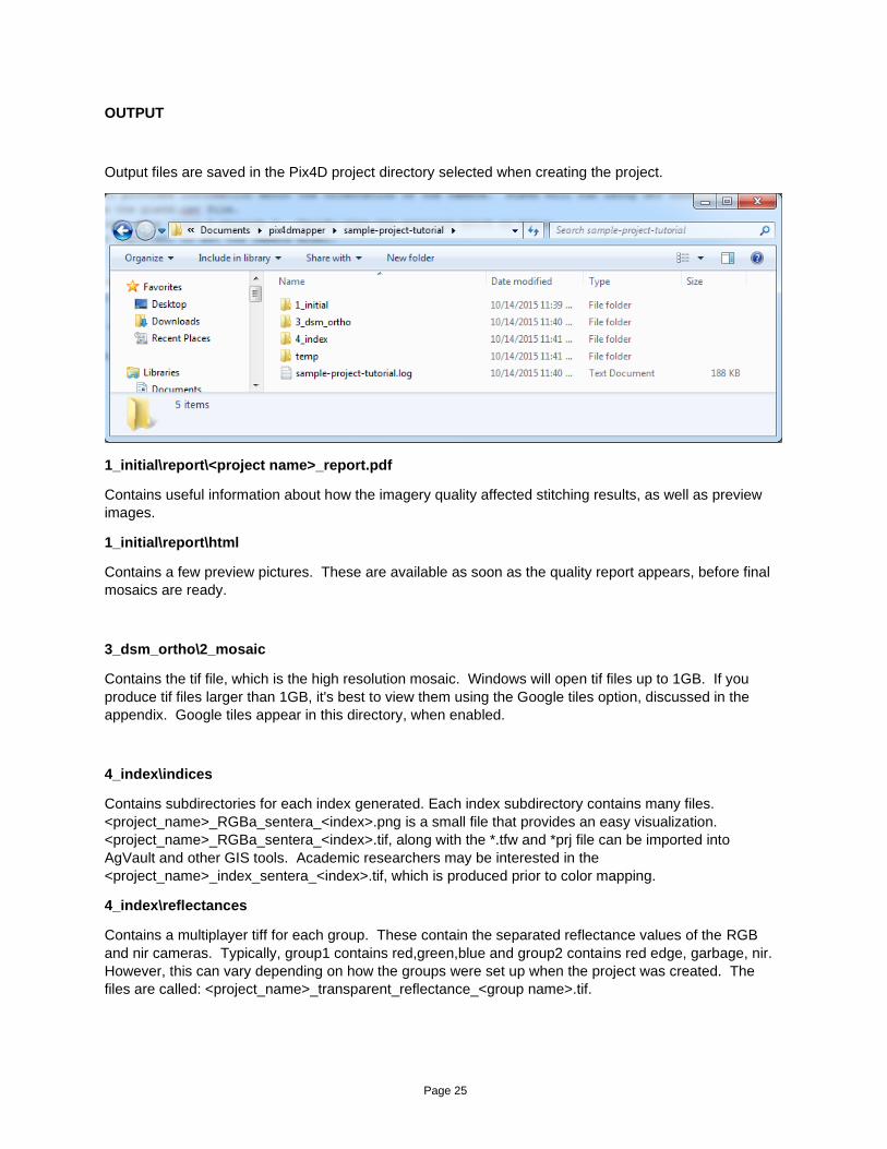
OUTPUT
Output files are saved in the Pix4D project directory selected when creating the project.
1_initial\report\<project name>_report.pdf
Contains useful information about how the imagery quality affected stitching results, as well as preview
images.
1_initial\report\html
Contains a few preview pictures. These are available as soon as the quality report appears, before final
mosaics are ready.
3_dsm_ortho\2_mosaic
Contains the tif file, which is the high resolution mosaic. Windows will open tif files up to 1GB. If you
produce tif files larger than 1GB, it's best to view them using the Google tiles option, discussed in the
appendix. Google tiles appear in this directory, when enabled.
4_index\indices
Contains subdirectories for each index generated. Each index subdirectory contains many files.
<project_name>_RGBa_sentera_<index>.png is a small file that provides an easy visualization.
<project_name>_RGBa_sentera_<index>.tif, along with the *.tfw and *prj file can be imported into
AgVault and other GIS tools. Academic researchers may be interested in the
<project_name>_index_sentera_<index>.tif, which is produced prior to color mapping.
4_index\reflectances
Contains a multiplayer tiff for each group. These contain the separated reflectance values of the RGB
and nir cameras. Typically, group1 contains red,green,blue and group2 contains red edge, garbage, nir.
However, this can vary depending on how the groups were set up when the project was created. The
files are called: <project_name>_transparent_reflectance_<group name>.tif.

Page 26

Page 27
APPENDIX A - LARGE DATA SETS
Large data sets mosaicked at high resolution can produce a merged GeoTIFF file larger than 1GB.
Windows will not display tiff files larger than 1GB, so an alternative viewing method is required. In this
case, it is recommended to enable Google Maps Tiles and KML. Doing so produces an HTML file and
KML file in the 3_dsm_ortho\2_mosaic directory. Double click on the HTML file to view tiled imagery in a
web browser. You may need to select “Allow” since some browsers disable tiled viewing by default.
Install Google Earth, then double click on the KML file to open the mosaic in Google Earth. Tiled viewing
allows lower resolution images to be viewed when zoomed out, and higher resolution images to be
viewed when zoomed in, which can provide an excellent viewing experience. However, generating the
Google Maps Tiles and KML adds substantial processing time to each stitching run, and should only be
enabled if it will really be used. In these cases, the GeoTIFF can optionally be disabled, if it will not be
used.
Page 28
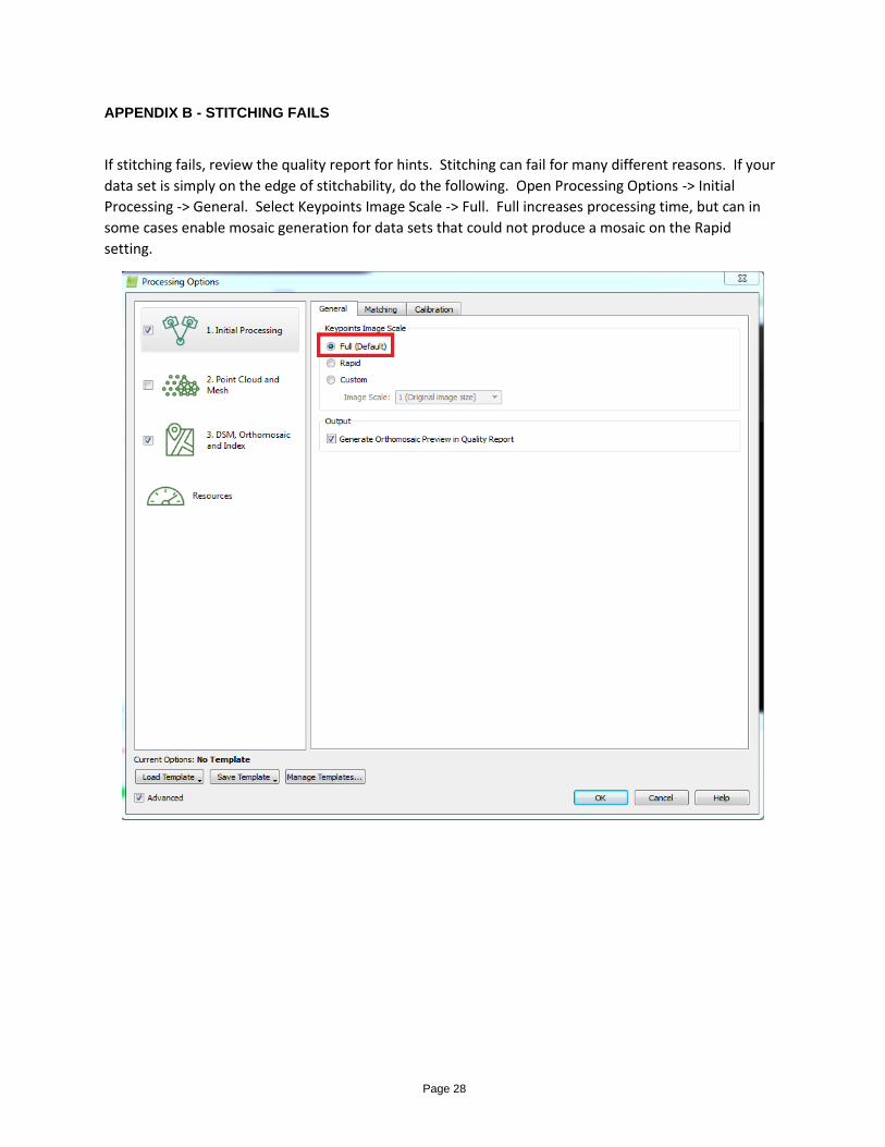
APPENDIX B - STITCHING FAILS
If stitching fails, review the quality report for hints. Stitching can fail for many different reasons. If your
data set is simply on the edge of stitchability, do the following. Open Processing Options -> Initial
Processing -> General. Select Keypoints Image Scale -> Full. Full increases processing time, but can in
some cases enable mosaic generation for data sets that could not produce a mosaic on the Rapid
setting.

Page 29
APPENDIX C - SAVING TEMPLATES
After creating indices, it’s possible to generate the indices as a step of the main processing. Open the
Processing Options, Select “3. DSM, Orthomosaic and Index”, and select “Index Calculator” tab. Check
the boxes next to the indices you want to generate each time and save the template. Load the template
next time. Note that even when Pix4D generates the indices, there is no way to automatically export
the color mapped versions of the indices. It is necessary to manually select the index and choose
“Export” to generate color mapped files.
Page 30
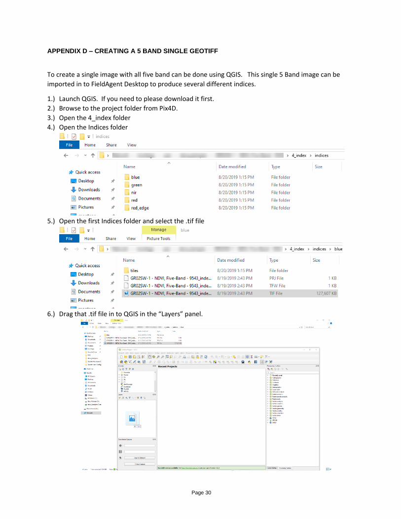
APPENDIX D – CREATING A 5 BAND SINGLE GEOTIFF
To create a single image with all five band can be done using QGIS. This single 5 Band image can be
imported in to FieldAgent Desktop to produce several different indices.
1.) Launch QGIS. If you need to please download it first.
2.) Browse to the project folder from Pix4D.
3.) Open the 4_index folder
4.) Open the Indices folder
5.) Open the first Indices folder and select the .tif file
6.) Drag that .tif file in to QGIS in the “Layers” panel.
Page 31
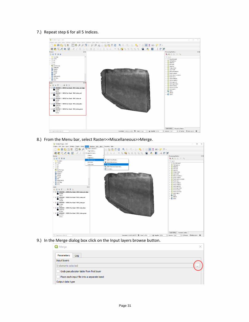
7.) Repeat step 6 for all 5 Indices.
8.) From the Menu bar, select Raster>>Miscellaneous>>Merge.
9.) In the Merge dialog box click on the Input layers browse button.
Page 32
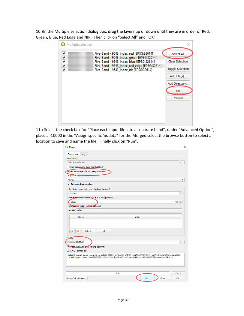
10.) In the Multiple selection dialog box, drag the layers up or down until they are in order or Red,
Green, Blue, Red Edge and NIR. Then click on “Select All” and “OK”
11.) Select the check box for “Place each input file into a separate band”, under “Advanced Option”,
place a -10000 in the ”Assign specific ‘nodata” for the Merged select the browse button to select a
location to save and name the file. Finally click on “Run”.
Page 33
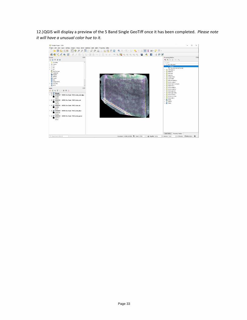
12.) QGIS will display a preview of the 5 Band Single GeoTiff once it has been completed. Please note
it will have a unusual color hue to it.
Page 34
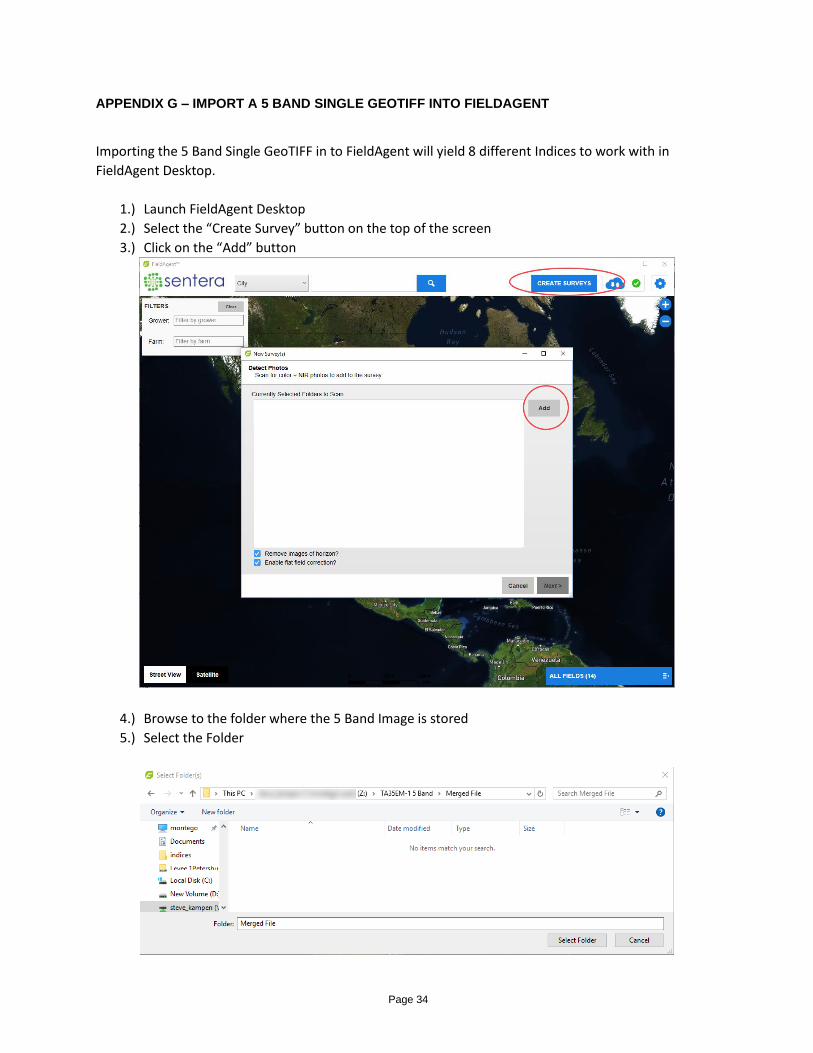
APPENDIX G – IMPORT A 5 BAND SINGLE GEOTIFF INTO FIELDAGENT
Importing the 5 Band Single GeoTIFF in to FieldAgent will yield 8 different Indices to work with in
FieldAgent Desktop.
1.) Launch FieldAgent Desktop
2.) Select the “Create Survey” button on the top of the screen
3.) Click on the “Add” button
4.) Browse to the folder where the 5 Band Image is stored
5.) Select the Folder
Page 35
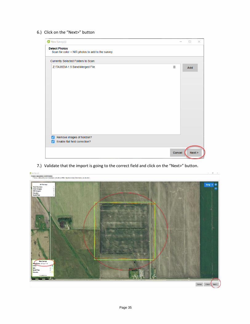
6.) Click on the “Next>” button
7.) Validate that the import is going to the correct field and click on the “Next>” button.
Page 36
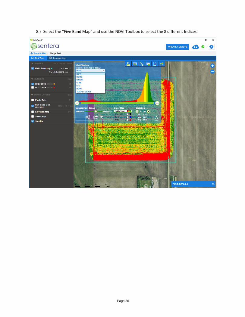
8.) Select the “Five Band Map” and use the NDVI Toolbox to select the 8 different Indices.