Embed Size (px)
Citation preview
DNA-BASED COMPUTING FOR SECURE CIRCUITRY DESIGN
By
Christy Marie (Bogard) Gearheart B.S., University of Louisville, 2004
M.Eng., University of Louisville, 2006 MBA, University of Louisville, 2006
A Dissertation Submitted to the Faculty of the
Speed School of Engineering of the University of Louisville in Partial Fulfillment of the Requirements
for the Degree of
Doctor of Philosophy
Computer Engineering & Computer Science Department University of Louisville
Louisville, Kentucky
May 2010
Copyright 2010 by Christy Marie (Bogard) Gearheart
All rights reserved

ii
DNA-BASED COMPUTING FOR SECURE CIRCUITRY DESIGN
By
Christy Marie (Bogard) Gearheart B.S., University of Louisville, 2004
M.Eng., University of Louisville, 2006 MBA, University of Louisville, 2006
A Dissertation Approved on
March 26, 2010
by the following Dissertation Committee:
_______________________________ Dr. Eric Rouchka, Co-Advisor
_______________________________ Dr. Benjamin Arazi, Co-Advisor
_______________________________ Dr. Ahmed Desoky
_______________________________ Dr. Ibrahim Imam
_______________________________ Dr. Palaniappan Sethu

iii
DEDICATION
To Jason, for letting me be no other than myself

iv
ACKNOWLEDGMENTS
While only my name is on the cover, I owe many thanks to all those who
made this dissertation possible:
• To my advisors, Drs. Eric C. Rouchka and Benjamin Arazi, for their
inspirational guidance. Both of these men have given me a deep
appreciation of academic excellence achieved through hard work
towards high goals.
• To my family, for endless encouragement and patience.
• To Hank and Becky Conn, who have been proud and supportive in all
of my endeavors culminating with this dissertation.
• To the members of my doctoral committee, Drs Ahmed Desoky,
Ibrahim Imam, and Palaniappan Sethu, for their time and valued
feedback.
This work was supported in part by NIH-NCRR Grant P20RR16481 and
NIH-NIEHS Grant P30ES014443. Its contents are solely the responsibility of the
authors and do not represent the official views of NCRR, NIEHS, or NIH.
v
ABSTRACT DNA-BASED COMPUTING FOR SECURE CIRCUITRY DESIGN
Christy M. Gearheart
March 26, 2010
Traditional silicon-based circuitry is susceptible to security attacks as a
consequence of the static nature of its design. Once a circuit is obtained by an
attacker, it is a matter of time before one can reverse engineer its configuration.
To circumvent such tampering, circuits must be dynamic by nature. A DNA-
based design enables circuitry to be based on biochemical and environmental
stimuli. As a first step, biological methodologies have been developed to mimic
existing silicon-based technologies in information storage, random number
generation, and a shift register. With each of these new theories introduced, we
move closer to the practical applications afforded by DNA computing. It is
unrealistic to predict that DNA computing will form the sole basis of the next
generation of technology; however, when combined with current technologies, it
could form a hybridization capable of achieving the fast computational benefits of
DNA with the flexibility of current silicon. Regardless of what the future may hold,
this research further develops DNA-based methodologies to mimic digital data
manipulation.
vi
TABLE OF CONTENTS
OVERVIEW .......................................................................................................... 1
INTRODUCTION TO BIOLOGY FOR THE COMPUTER SCIENTIST ................. 4
1. EVOLUTION OF THE ORGANISM THROUGH CELLS ...................................... 4
2. FROM CELLS TO DNA....................................................................................... 7
3. FROM DNA TO AMINO ACIDS .........................................................................10
4. THE CENTRAL DOGMA OF MOLECULAR BIOLOGY ......................................12
5. READING THE DNA SEQUENCE .....................................................................16
6. BIOGRAPHICAL NOTES...................................................................................18
DESIGNING BIOLOGICAL LOGIC GATES........................................................ 19
1. CHEMICAL APPROACHES TO LOGIC GATES ................................................20
2. DNA-BASED LOGIC GATES .............................................................................22
2.1 DNA Computation as a SAT Problem.........................................................23
2.2 DNA Computation Through Site Directed Mutagenesis ..............................25
2.3 Experimental Verification of DNA Computation ..........................................27
2.4 Reducing Time Complexity to Depth of Circuit ...........................................29
2.5 In-vivo Computation: Moving Computation Inside of the Cell......................31
2.6 From Logic Gates to Logic Circuits.............................................................33
3. DNA ARITHMETIC ............................................................................................34
3.1 Arithmetic Computation ..............................................................................35
3.2 The Subset-Sum Problem ..........................................................................37
3.3 Arithmetic Working Backwards: Factoring Integers.....................................38
DNA MEDIA STORAGE ..................................................................................... 40
1. DNA REPRESENTATION OF DIGITAL INFORMATION ...................................40
2. ADLEMAN AND THE HAMILTONIAN PATH PROBLEM ...................................41
3. USING MULTIPLE SEQUENCE ALIGNMENT IN ERROR REDUCTION...........45
3.1 Multiple sequence alignment ......................................................................46
3.2 Multiple Sequence Alignment for Error Reduction ......................................47
3.3 Improving the Multiple Sequence Alignment...............................................48
3.4 Heuristic Improvements of the Algorithm ....................................................49
4. DISCUSSION ....................................................................................................50
vii
RANDOM NUMBER GENERATION CIRCUITRY.............................................. 53
1. OLIGONUCLEOTIDE SYNTHESIS....................................................................56
2. RANDOM NUMBER GENERATION WITH DNA................................................57
3. PHYSICALLY SYNTHESIZING THE RANDOM NUMBER SEQUENCE ............58
4. TEMPORARY STORAGE OF RANDOM NUMBERS.........................................58
5. RANDOM NUMBER GENERATION CIRCUITRY ..............................................60
6. CIRCUIT FABRICATION CONSIDERATIONS...................................................64
7. EVALUATING RANDOMNESS..........................................................................65
8. SIMULATING THE RANDOM NUMBER GENERATION CIRCUITRY ...............66
9. JUSTIFICATION FOR DNA-BASED RANDOM NUMBER GENERATION .........74
DESIGN OF A DNA-BASED SHIFT REGISTER................................................ 76
1. DNA-BASED LOGIC GATES .............................................................................78
1.1 Gate Inputs ................................................................................................79
1.2 Detection of Sequences .............................................................................80
1.3 NOT Gate...................................................................................................84
1.4 XOR Gate ..................................................................................................85
1.5 OR Gate.....................................................................................................86
1.6 NAND Gate ................................................................................................88
1.7 AND, NOR, and XNOR Gates ....................................................................90
1.8 Obfuscating the Logic Gates ......................................................................90
1.9 From Logic Gates to Circuits ......................................................................92
1.10 Non-Boolean DNA-Based Logic Gates.......................................................94
2. THE SHIFTING ELEMENT ................................................................................97
2.1 Biological Approach to Shifting ...................................................................97
2.2 Implementing Alternative Splicing.............................................................100
2.3 Temporary Storage of DNA Sequences ...................................................101
3. CIRCUIT FABRICATION .................................................................................102
CONCLUSION.................................................................................................. 104
REFERENCES................................................................................................. 108
RANDOM NUMBER GENERATION SIMULATION PSEUDOCODE ............... 115
CURRICULUM VITAE ...................................................................................... 118
viii
LIST OF TABLES
Table 1: Amino Acid Translation Table............................................................... 11
Table 2: Unique Combinations for Single Input DNA AND Logic Gate ............... 24
Table 3: P-Values of the RNG Simulation with Nucleotide Replacement. .......... 70
Table 4. P-Values of Sample Sets When Compared with 1 Million Samples ..... 74
Table 5: Logical Output Value for Pairs of Nucleotide Inputs ............................. 95
ix
LIST OF FIGURES
Figure 1: Eukaryotic Cell Structure ....................................................................... 6
Figure 2: Chemical Compositions of the Four DNA Nucleotides .......................... 8
Figure 3: Polynucleotide Chain............................................................................. 9
Figure 4: Orientation of Polynucleotide Chain ...................................................... 9
Figure 5: DNA Double Helix Formation .............................................................. 10
Figure 6: Complementary Polynucleotide Sequences ........................................ 10
Figure 7: Translation of a DNA Sequence .......................................................... 12
Figure 8: DNA Replication .................................................................................. 13
Figure 9: Alternative Splicing.............................................................................. 14
Figure 10: Central Dogma of Molecular Biology ................................................. 15
Figure 11: Chromatogram .................................................................................. 18
Figure 12: Chemically-Based Fluorescent NOT Gate......................................... 20
Figure 13: Raymo’s Compound.......................................................................... 21
Figure 14: Graphical Representation of a Two-Bit Binary Number ..................... 24
Figure 15: DNA-Based Algorithm for the Addition of Two Binary Bits................. 36
Figure 16: Conversion Between Digital Bit-Based and DNA-Based Alphabet .... 41
Figure 17: Traveling Salesman Problem (TSP) .................................................. 42
Figure 18: DNA Representation of the Traveling Salesman Problem................. 44
x
Figure 19: DNA Sequences Representing Stored Information ........................... 51
Figure 20: Alignment of the eight nucleotide sequences ................................... 51
Figure 21: Translation of polynucleotide chain into amino acid chain................. 52
Figure 22: Alignment of Amino Acid Sequences from Figure 19 ........................ 52
Figure 23: Insertion of chromosomal DNA into a plasmid vector ....................... 60
Figure 24: Random Number Generation Circuitry .............................................. 62
Figure 25: Expected melting point distribution ................................................... 72
Figure 26: Expected distributions from observations ......................................... 73
Figure 27: Complementary sequences .............................................................. 79
Figure 28: Dynamic assignment of gate input sequences ................................. 80
Figure 29: Examples of attachment sites to fluorescently label nucleotides ....... 82
Figure 30: DNA-Based Implementation of the NOT Gate................................... 85
Figure 31: DNA-Based Implementation of the XOR Gate................................... 86
Figure 32: DNA-Based Implementation of the OR Gate ..................................... 87
Figure 33: DNA-Based Implementation of the NAND Gate ................................ 89
Figure 34: DNA-Based Circuit ............................................................................ 93
Figure 35: Alternative splicing............................................................................. 98
Figure 36: Exonic regions spliced by intronic regions ........................................ 99
Figure 37: Spliced inputs based on selection of restriction enzymes ............... 101
1
CHAPTER I
OVERVIEW
DNA-based circuit design is an area of research in which traditional
silicon-based technologies are replaced by naturally occurring phenomena taken
from biochemistry and molecular biology. Fully functional DNA computation can
be aided by developing DNA paradigms for converting traditional digital circuitry.
Chronological development of molecular logic gates is examined, focusing
on both chemical and biological approaches that have been proposed. This
research focuses on further developing DNA-based methodologies to mimic
digital data manipulation, demonstrating how DNA can be utilized to store,
generate and process data.
Within the digital world, data manipulation encompasses a number of
essential processes, including data generation, storage, retrieval, and
processing. In terms of complexity, data storage and retrieval is considered the
least difficult. A novel approach in which DNA could be used as a means of
storing files is presented. Direct substitution of two binary base pairs encoding
for a single quaternary character enables translation between the computer
scientist’s alphabet and the geneticist’s representations. Multiple sequence
alignment combined with intelligent heuristics enable the most probabilistic file
2
contents to be determined with minimal errors. Completely conserved regions
have no discrepancies and as such are 100% error-free. Highly conserved
regions have minimal discrepancies, whose correct content can be determined
based on the emission probabilities of the associated Hidden Markov Model.
Finally, poorly conserved regions with high discrepancies and low-emission
probabilities can be overcome using the associated translated amino acid
sequences.
Having shown a methodology by which data can be accurately stored and
retrieved, the next research component is to devise a methodology by which one
could generate information. A Random Number Generation Circuitry
demonstrates how a microfluidic device can generate meaningful data using
DNA sequences. A novel prototype schema employs solid-phase synthesis of
oligonucleotides for random construction of DNA sequences; temporary storage
is achieved through plasmid vectors; and chromatogram analysis enables the
translation from a sequence to its digitally equivalent random number. Long term
storage is achieved through spotted microarray fabrication, which enables each
sequence’s expression levels to be permanently stored. A discussion of how to
evaluate sequence randomness is included, as well as how these techniques are
applied to a simulation of the random number generation circuitry. Simulation
results show generated sequences successfully pass three selected NIST
random number generation tests.
Finally, the design of a DNA-Based Shift Register concentrates on the
manipulation of data, demonstrating how information can be parsed through a
3
digital circuit comprised on DNA – based logic gates. A novel logic gate design
based on chemical reactions is presented in which observance of double
stranded sequences indicates a truth evaluation. Circuits are obfuscated by
removing physical sequence connections, allowing client-specific representative
strands for input sequences, altering the input sequence strands over time, and
varying the input sequence length. Shifting along the input stream to parse
individual inputs is accomplished through simulated alternative splicing of DNA
sequences stored in plasmid vectors.
With each of these new theories introduced, we move closer to the
practical applications afforded by DNA computing. It is unrealistic to predict DNA
computing will form the sole basis of the next generation of technology; however,
when combined with current technologies, could form a hybridization capable of
achieving the fast computational benefits of DNA with the flexibility of current
silicon. Regardless of what the future may hold, this research further develops
DNA-based methodologies to mimic digital data manipulation. Biological
methodologies have been developed to mimic existing silicon-based
technologies in information storage, random number generation, and a shift
register.
4
CHAPTER II
INTRODUCTION TO BIOLOGY FOR THE COMPUTER SCIENTIST
Bioinformatics, in its broadest terms, is defined by the National Center for
Biotechnology Information (NCBI) as “the field of science in which biology,
computer science, and information technology merge to form a single discipline”
[1]. According to the National Institutes of Health (NIH), “bioinformatics applies
the principles of information sciences and technologies to make the vast, diverse,
and complex life sciences data more understandable and useful” [2]. Thus, the
successful bioinformatist must be versed in both the theories and applications of
computer science and molecular biology. The proceeding chapter is designed to
provide the computer scientist a fundamental comprehension of molecular
biology. It is important to note that there are few absolute rules governing the
field of molecular biology and that this chapter is only intended as an introductory
approach. An excellent review of microbiology for the computer scientist is
presented by Lawrence Hunter in [3].
1. EVOLUTION OF THE ORGANISM THROUGH CELLS
All living organisms, regardless of their size, are composed of cells. A cell
is a complex system enclosed within a membrane that is the smallest sustainable
5
unit of life. Thus, the simplest organism is that consisting of a single cell.
Bacteria are one example of a unicellular organism. However, most organisms –
such as plants and animals – are multicellular. As organisms evolve, their cells
differentiate to perform specialized functions. For example, the human body
consists of approximately 60 trillion cells representing 320 different cell types
such as skin cells, red blood cells, muscle cells, and brain cells [4].
Organisms can be grouped into one of two large distinct groups known as
prokaryotes and eukaryotes. Prokaryotes are unicellular organisms lacking a
nucleus. Their cells are typically one micron in diameter and are often simpler in
structure than their eukaryotic counterparts. Given such a minute size, most
prokaryotes cannot be seen with the naked eye, but are visible with a
microscope.
Eukaryotes, which can be both unicellular and multicellular organisms, are
composed of cells having a nucleus as well as the presence of membrane-bound
organelles. The nucleus, which contains the genetic information of the cell, is
separated from the remaining cellular components by a nuclear membrane.
Eukaryotic cells are typically 10 to 100 microns in diameter, but because
eukaryotic cells often differentiate to perform a specialized function, there is no
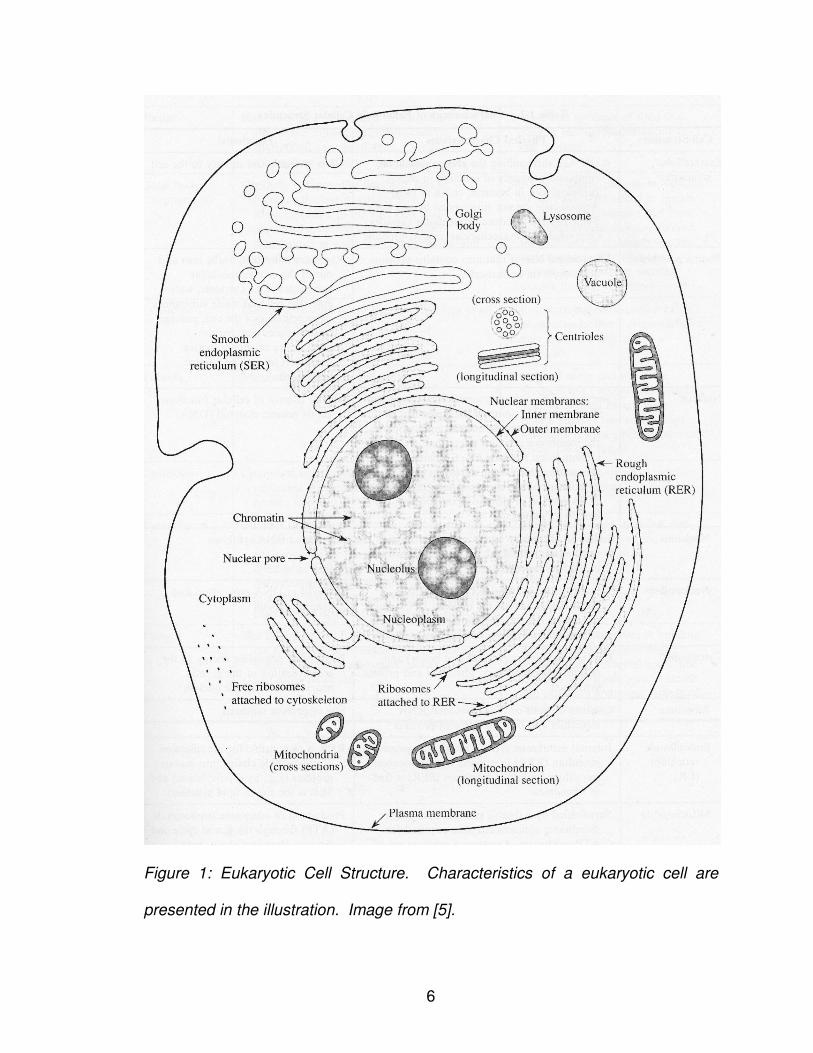
typical cell structure representing possible functions. Figure 1 shows a
eukaryotic cell with various subcellular functions presented.
6
Figure 1: Eukaryotic Cell Structure. Characteristics of a eukaryotic cell are
presented in the illustration. Image from [5].
7
2. FROM CELLS TO DNA
The genetic information stored in the cell’s nucleus, known as the
organism’s genome, determines the traits an organism will inherit from its
parents. Just as the eukaryotic structure is more complex than the prokaryotic
structure, eukaryotic genomes are often more complex than their prokaryotic
counterparts. However, the size of the eukaryotic genome is not indicative of the
organism’s complexity. For example, the human genome has one – tenth the
base pairs as the lily flower genome; clearly one would not conclude that the lily
is more complex than that of the human.
A eukaryotic organism’s genome is organized into chromosomes. Each
chromosome contains a number of genes, where in simplistic terms each gene
encodes for a single trait. The gene’s corresponding behavior is determined as
the combination of one allele (a single gene copy) inherited from the maternal
parent and one allele inherited from the paternal parent. Genes are stored within
chains of deoxyribonucleic acid molecules (DNA) called polynucleotide or
oligonucleotide chains. An oligonucleotide chain of n-bases is often abbreviated
as an n-mer. A polynucleotide chain consists of consecutively linked molecules
known as nucleotides. There are four DNA nucleotides – adenosine (A),
cytosine (C), guanine (G), and thymine (T) – that can be combined in varying
frequency and ordering to form a polynucleotide chain. The chemical
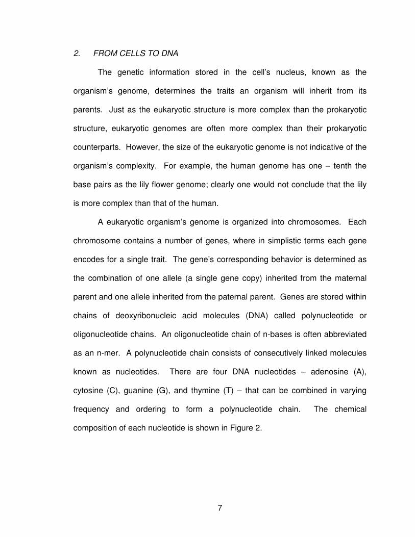
composition of each nucleotide is shown in Figure 2.
8
Figure 2: Chemical Compositions of the Four DNA Nucleotides adenine,
cytosine, guanine, and thymine. For RNA, uracil replaces the thymine
nucleotide. Adapted from [6].
Each nucleotide molecule is composed of a sugar – phosphate and
corresponding purine (adenosine and guanine) or pyramidine (cytosine and
thymine) base that distinguishes the molecules. Based on the chemical bonding
of the sugar – phosphate, the polynucleotide chain is said to have a 5’ (“five
prime”) or 3’ (“three prime”) orientation. Thus, the polynucleotide chain illustrated
in Figure 3 has an associated orientation that defines how the molecules are
bonded. Conventions dictate that sequences are often written 5’ left and 3’ right,
and as such, the 5’ and 3’ notations are not always provided.
9
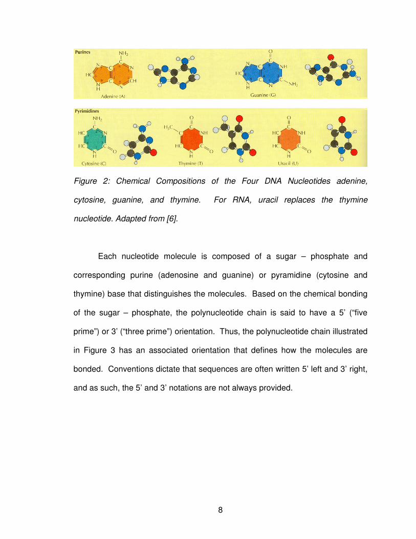
T–G–T–C–A–T–A–G–G–A–T–A–A–G–C
Figure 3: Polynucleotide Chain. A polynucleotide chain contains a combination
of nucleotides in any order of any length. This chain, called a 15-mer, contains
fifteen nucleotide bases comprised of five adenosine (A), two cytosine (C), four
guanine (G), and four thymine (T) molecules.
5’ T�G�T�C�A�T�A�G�G�A�T�A�A�G�C 3’
Figure 4: Orientation of Polynucleotide Chain. The bonding of the composing
molecules of a polynucleotide chain dictates the chain’s orientation as either 5’ or
3’, typically written with the 5’ region on the left and the 3’ region on the right.
In addition to bonding nucleotide molecules to form a sequence strand,
two sequences can bond together to form the classical DNA double helix
structure (Figure 5) through a process called annealing. To bond, the nucleotide
bases of one sequence must sequentially bond with the complementary bases of
the second sequence with reversed polarity. Adenosine and thymine form
complementary bases as do cytosine and guanine. Hydrogen bonding between
the sequences maintains bonding in the double helix structure; there are two
hydrogen bonds between adenosine and thymine and three hydrogen bonds
between cytosine and guanine.
10
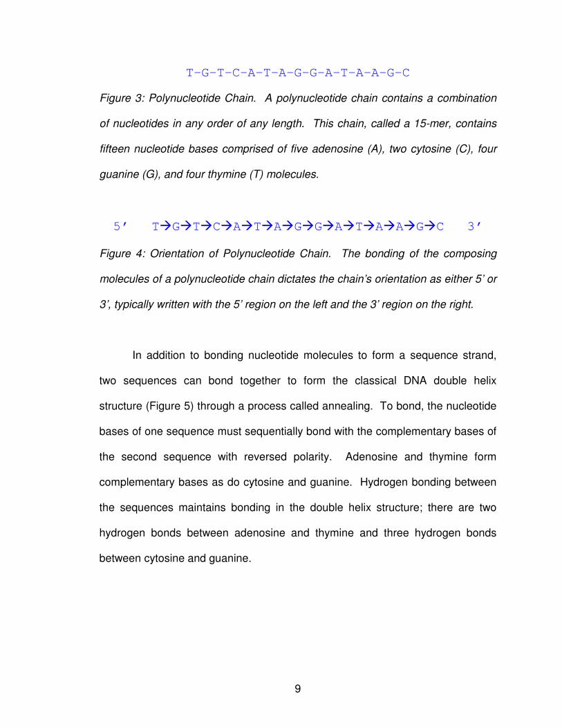
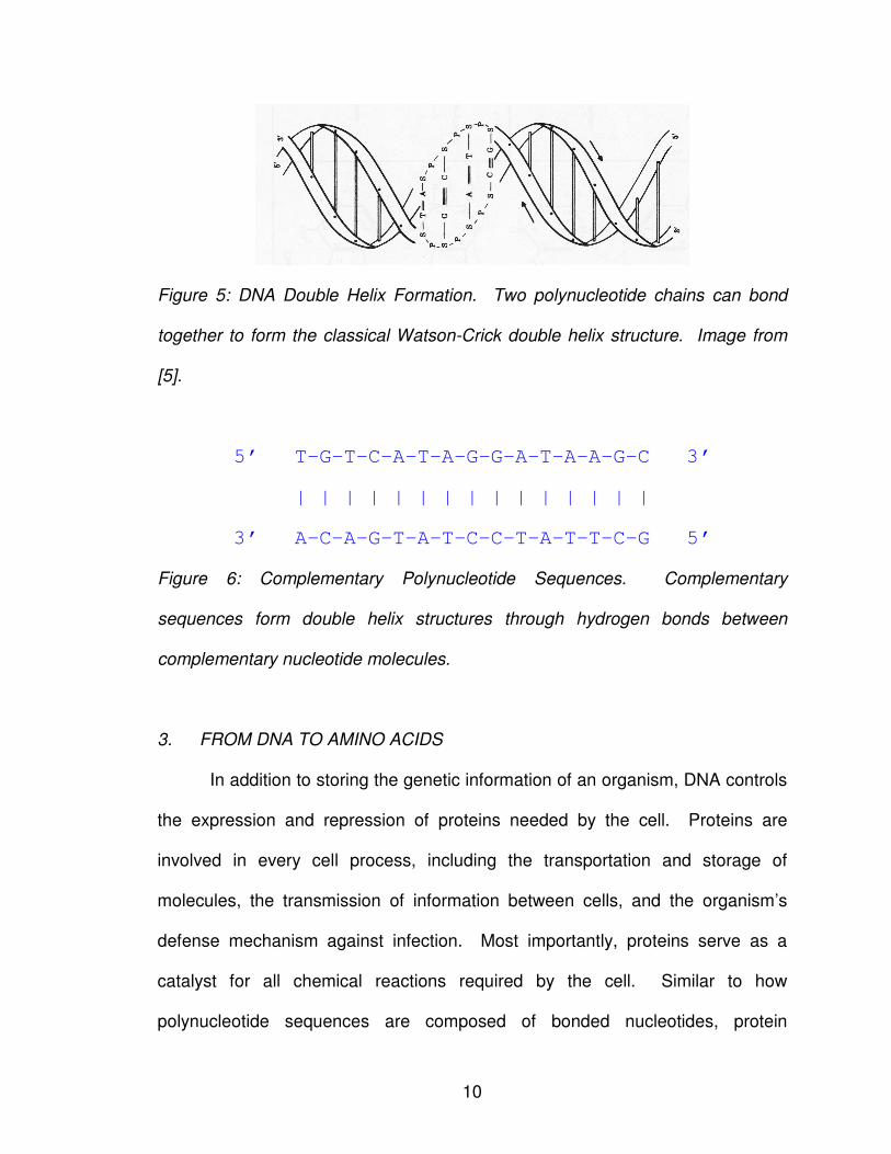
Figure 5: DNA Double Helix Formation. Two polynucleotide chains can bond
together to form the classical Watson-Crick double helix structure. Image from
[5].
5’ T–G–T–C–A–T–A–G–G–A–T–A–A–G–C 3’
| | | | | | | | | | | | | | |
3’ A–C–A–G–T–A–T–C–C–T–A–T–T–C–G 5’
Figure 6: Complementary Polynucleotide Sequences. Complementary
sequences form double helix structures through hydrogen bonds between
complementary nucleotide molecules.
3. FROM DNA TO AMINO ACIDS
In addition to storing the genetic information of an organism, DNA controls
the expression and repression of proteins needed by the cell. Proteins are
involved in every cell process, including the transportation and storage of
molecules, the transmission of information between cells, and the organism’s
defense mechanism against infection. Most importantly, proteins serve as a
catalyst for all chemical reactions required by the cell. Similar to how
polynucleotide sequences are composed of bonded nucleotides, protein
11
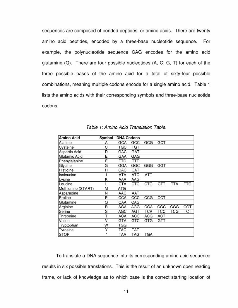
sequences are composed of bonded peptides, or amino acids. There are twenty
amino acid peptides, encoded by a three-base nucleotide sequence. For
example, the polynucleotide sequence CAG encodes for the amino acid
glutamine (Q). There are four possible nucleotides (A, C, G, T) for each of the
three possible bases of the amino acid for a total of sixty-four possible
combinations, meaning multiple codons encode for a single amino acid. Table 1
lists the amino acids with their corresponding symbols and three-base nucleotide
codons.
Table 1: Amino Acid Translation Table.
Amino Acid Symbol
Alanine A GCA GCC GCG GCT
Cysteine C TGC TGT
Aspartic Acid D GAC GAT
Glutamic Acid E GAA GAG
Phenylalanine F TTC TTT
Glycine G GGA GGC GGG GGT
Histidine H CAC CAT
Isoleucine I ATA ATC ATT
Lysine K AAA AAG
Leucine L CTA CTC CTG CTT TTA TTG
Methionine (START) M ATG
Asparagine N AAC AAT
Proline P CCA CCC CCG CCT
Glutamine Q CAA CAG
Arginine R AGA AGG CGA CGC CGG CGT
Serine S AGC AGT TCA TCC TCG TCT
Threonine T ACA ACC ACG ACT
Valine V GTA GTC GTG GTT
Tryptophan W TGG
Tyrosine Y TAC TAT
STOP * TAA TAG TGA
DNA Codons
To translate a DNA sequence into its corresponding amino acid sequence
results in six possible translations. This is the result of an unknown open reading
frame, or lack of knowledge as to which base is the correct starting location of
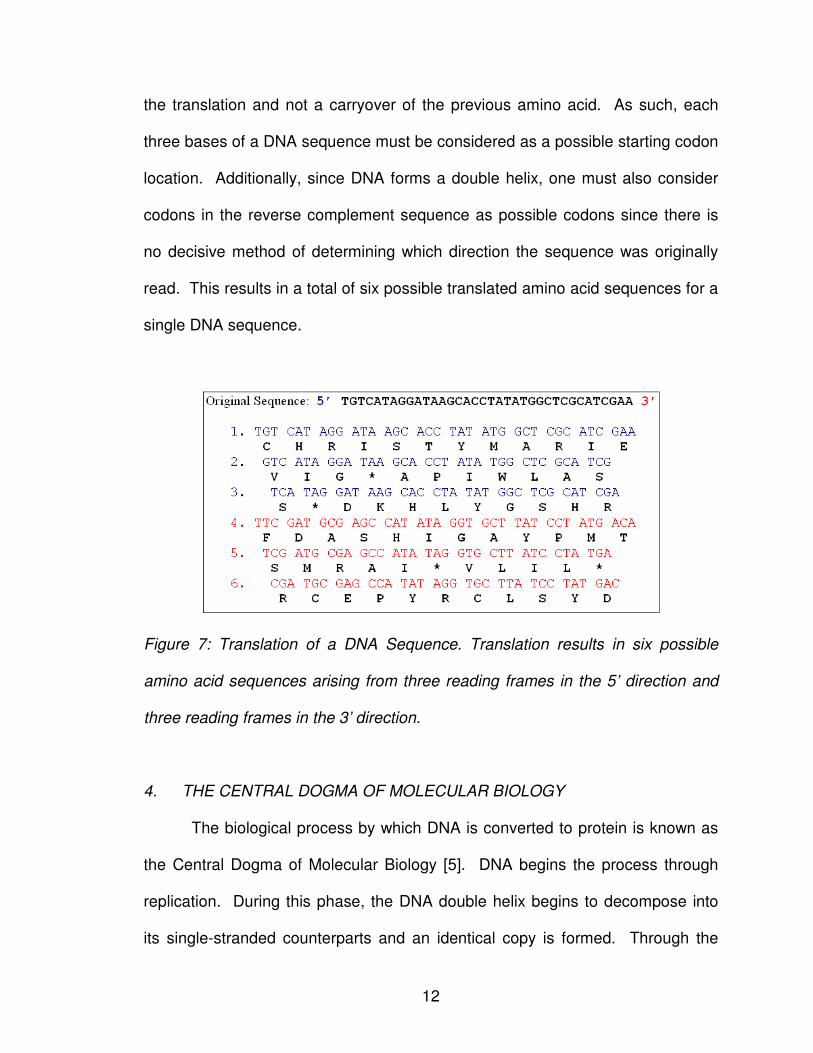
12
the translation and not a carryover of the previous amino acid. As such, each
three bases of a DNA sequence must be considered as a possible starting codon
location. Additionally, since DNA forms a double helix, one must also consider
codons in the reverse complement sequence as possible codons since there is
no decisive method of determining which direction the sequence was originally
read. This results in a total of six possible translated amino acid sequences for a
single DNA sequence.
Figure 7: Translation of a DNA Sequence. Translation results in six possible
amino acid sequences arising from three reading frames in the 5’ direction and
three reading frames in the 3’ direction.
4. THE CENTRAL DOGMA OF MOLECULAR BIOLOGY
The biological process by which DNA is converted to protein is known as
the Central Dogma of Molecular Biology [5]. DNA begins the process through
replication. During this phase, the DNA double helix begins to decompose into
its single-stranded counterparts and an identical copy is formed. Through the
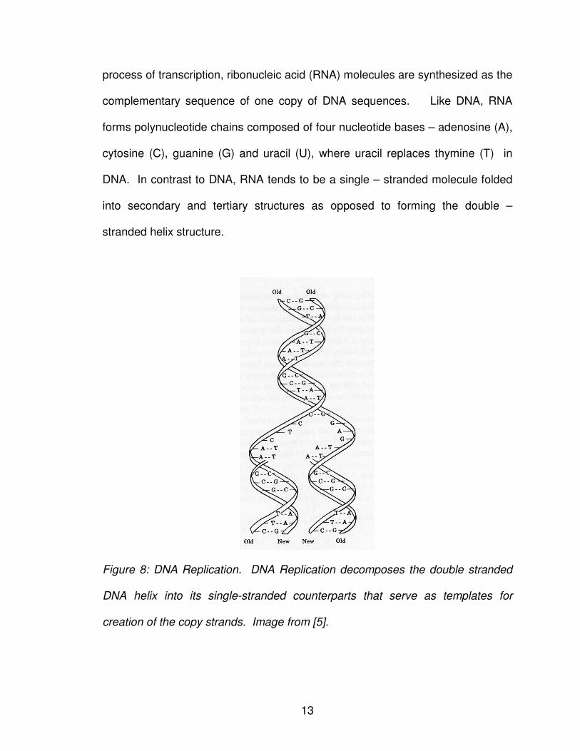
13
process of transcription, ribonucleic acid (RNA) molecules are synthesized as the
complementary sequence of one copy of DNA sequences. Like DNA, RNA
forms polynucleotide chains composed of four nucleotide bases – adenosine (A),
cytosine (C), guanine (G) and uracil (U), where uracil replaces thymine (T) in
DNA. In contrast to DNA, RNA tends to be a single – stranded molecule folded
into secondary and tertiary structures as opposed to forming the double –
stranded helix structure.
Figure 8: DNA Replication. DNA Replication decomposes the double stranded
DNA helix into its single-stranded counterparts that serve as templates for
creation of the copy strands. Image from [5].
14
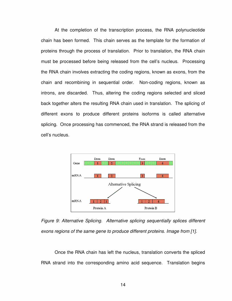
At the completion of the transcription process, the RNA polynucleotide
chain has been formed. This chain serves as the template for the formation of
proteins through the process of translation. Prior to translation, the RNA chain
must be processed before being released from the cell’s nucleus. Processing
the RNA chain involves extracting the coding regions, known as exons, from the
chain and recombining in sequential order. Non-coding regions, known as
introns, are discarded. Thus, altering the coding regions selected and sliced
back together alters the resulting RNA chain used in translation. The splicing of
different exons to produce different proteins isoforms is called alternative
splicing. Once processing has commenced, the RNA strand is released from the
cell’s nucleus.
Figure 9: Alternative Splicing. Alternative splicing sequentially splices different
exons regions of the same gene to produce different proteins. Image from [1].
Once the RNA chain has left the nucleus, translation converts the spliced
RNA strand into the corresponding amino acid sequence. Translation begins
15
with the amino acid methionine (M), represented by the codon AUG, and
continues until one of three stop codons is reached – UAA, UAG, or UGA. The
translated amino acids form the template used to create the desired protein [7].
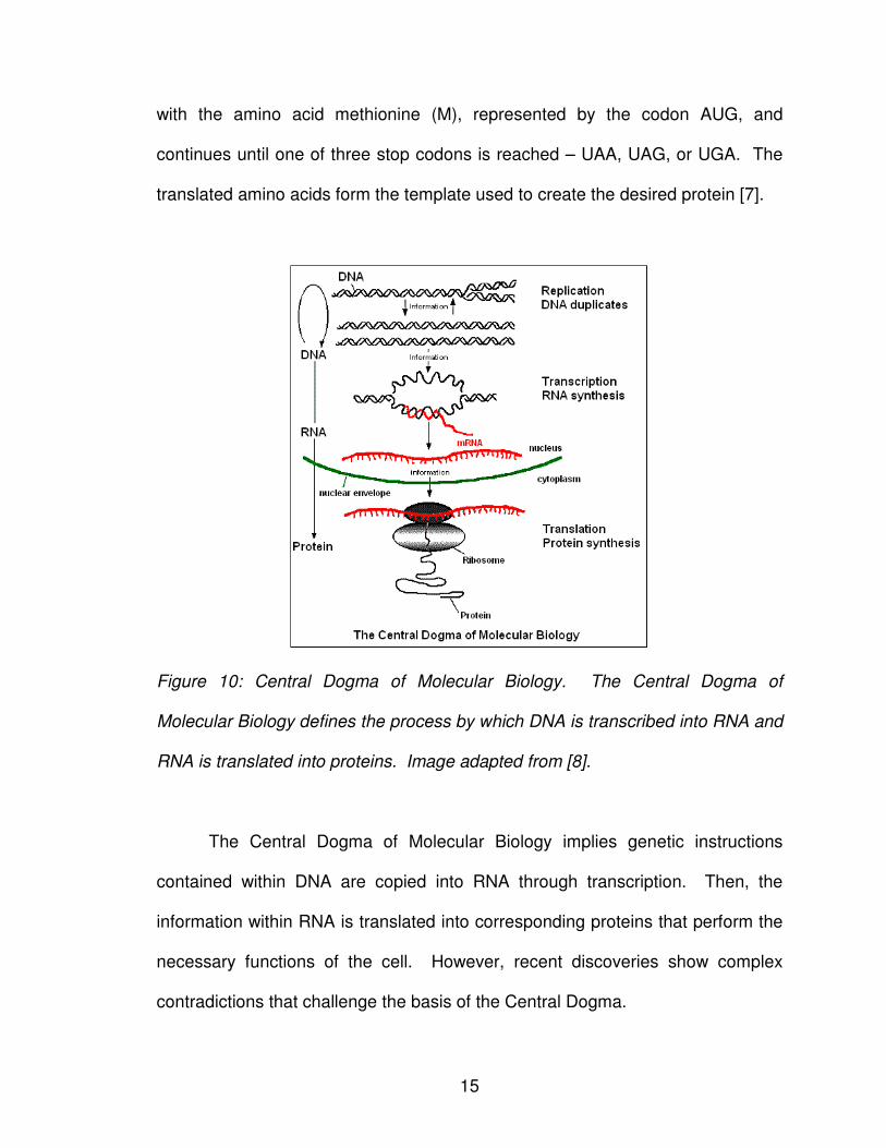
Figure 10: Central Dogma of Molecular Biology. The Central Dogma of
Molecular Biology defines the process by which DNA is transcribed into RNA and
RNA is translated into proteins. Image adapted from [8].
The Central Dogma of Molecular Biology implies genetic instructions
contained within DNA are copied into RNA through transcription. Then, the
information within RNA is translated into corresponding proteins that perform the
necessary functions of the cell. However, recent discoveries show complex
contradictions that challenge the basis of the Central Dogma.
16
First, RNA viruses have been discovered that result in the reverse
transcription of RNA back into DNA through reverse transcriptase proteins,
contradicting the directed transcription of DNA into RNA [9]. The discovery of
microRNAs performing as proteins contradicted the belief that cell functions were
completed solely by protein. Most recently, it was determined that microRNAs
alter the RNA in such a manner as to prevent its translation into proteins
altogether [10]. The microRNA binds to the RNA to form a double-stranded helix,
preventing the RNA from being translated into a protein.
Scientists are still discovering the relationship complexities among cellular
elements. Thus, the simplified model of the Central Dogma of Molecular Biology
cannot adequately describe the vast interactions occurring. Even at the
foundation, there are few absolute rules governing the field of molecular biology.
5. READING THE DNA SEQUENCE
Fluorescent labels are introduced to observe the nucleotide present at a
given location. Fluorescent molecules can be attached to the nucleotide
sequence, which in turn absorb and emit light at a particular wavelength. One
efficient methodology to fluorescently label a nucleotide sequence is through
direct bonding of the fluorescent dye to the sequence chain. Fluorescent dyes
can bond to the nucleotide sequence through the sugar ring, the phosphate
backbone, or directly to the nucleotide itself [11]. To label the sugar ring, DNA
depurination frees the aldehde group of the terminating sugar (5’ or 3’ end) such
that it can now form a covalent bond with the fluorescent agent. Conversely,
17
labeling the phosphate backbone is achieved by synthesizing a dansyl derivative
that will directly react with the 5’-phosphate end of the nucleotide chain.
Directly labeling the nucleotide base involves reacting with one or more of
the positional bases of the nucleotides. Because the single stranded sequence
will be utilized in sequence pairing in the presence of the complementary strand,
it is critical the fluorescent dye reaction not interfere with sites involved in base
pairing. Pyrimidine (thymine and adenine) labeling can be achieved through a
cyclo-addition reaction at the 5th- and 6th- positions, while purine (cytosine and
guanine) labeling can be achieved through an acetamide reaction at the 8th-
position.
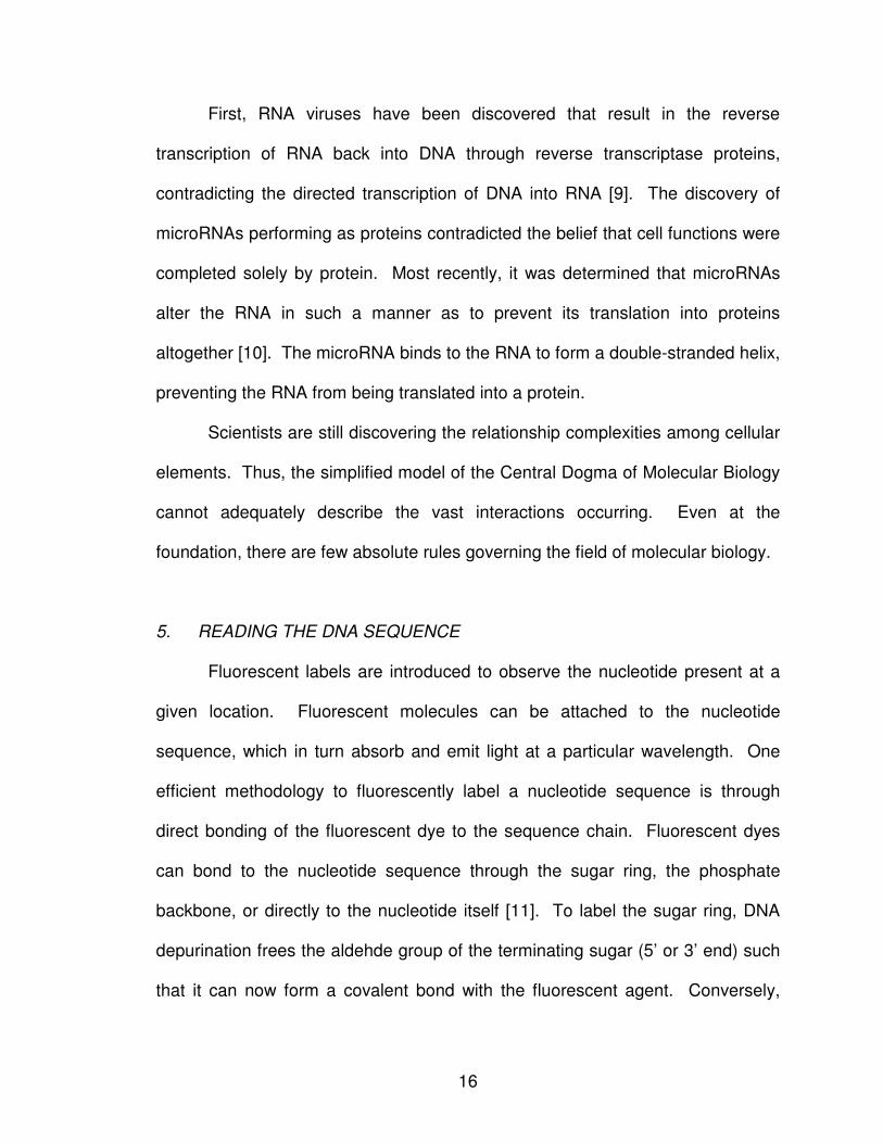
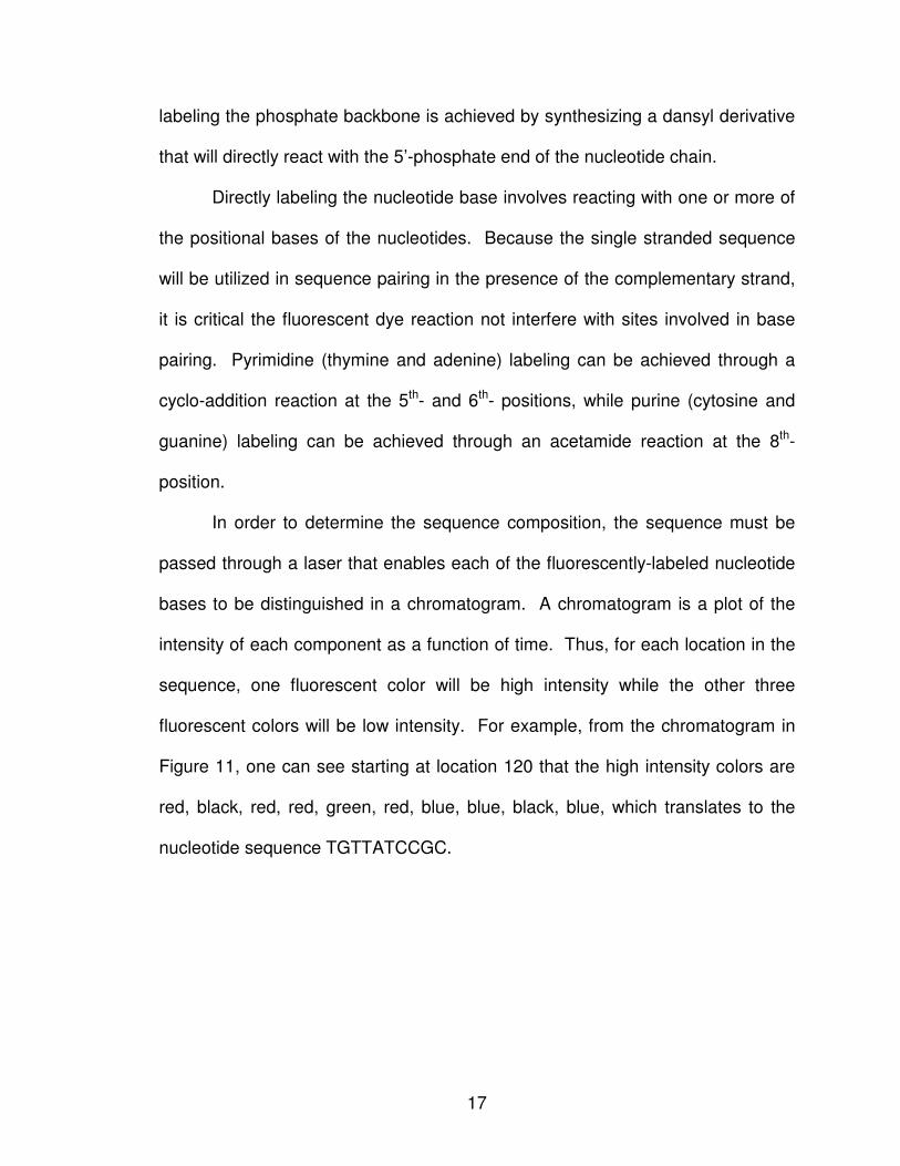
In order to determine the sequence composition, the sequence must be
passed through a laser that enables each of the fluorescently-labeled nucleotide
bases to be distinguished in a chromatogram. A chromatogram is a plot of the
intensity of each component as a function of time. Thus, for each location in the
sequence, one fluorescent color will be high intensity while the other three
fluorescent colors will be low intensity. For example, from the chromatogram in
Figure 11, one can see starting at location 120 that the high intensity colors are
red, black, red, red, green, red, blue, blue, black, blue, which translates to the
nucleotide sequence TGTTATCCGC.
18
Figure 11: Chromatogram. Chromatogram showing the intensity levels of
fluorescently-labeled nucleotides for a given oligonucleotide sequence. Image
from [12].
6. BIOGRAPHICAL NOTES
The information contained within this chapter is adapted from Genetics by
Susan Elrod and William Stansfield [5], The Cell: A Molecular Approach by
Geoffrey M. Cooper and Robert E. Hausman [6], and Fundamentals of Molecular
Biology by Dan Graur and Wen-Hsiung Li [13]. Additional information and
images were also adapted from the National Center for Biotechnology
Information (NCBI), the National Institutes of Health (NIH), the European
Bioinformatics Institute (EMBL – EBI), and the National Health Museum.
19
CHAPTER III
DESIGNING BIOLOGICAL LOGIC GATES
The concept that computers could be theoretically constructed with
biological elements was first envisioned by Richard Feynman in his 1959 talk
“Plenty of Room at the Bottom” [14]. Feynman was fascinated with the ability of
biological systems to not just store information, but to actively respond to it on an
exceedingly small level. He believed one could mimic these activities to achieve
the miniaturization of any object, including computers.
Some experts fully support Feynman’s hypothesis, believing that DNA
computers will one day replace their silicon-based counterparts, whereas others
believe the future of computing lies in the hybridization of silicon and DNA-based
components [15-25]. Regardless of what the future holds, DNA computing can
only progress by developing DNA paradigms to replicate traditional digital
counterparts. As such, DNA-based circuit design has formed as an area of
research in which traditional silicon-based technologies are replaced by naturally
occurring phenomena in biochemistry and molecular biology [26-28].
20
1. CHEMICAL APPROACHES TO LOGIC GATES
Before scientists were capable of devising DNA-based logic gates, they
devised logic gates based on chemical processes. There are a number of
techniques that have been used to accomplish this, the two most common being
photoinduced electron transfer (PET) and photochromics.
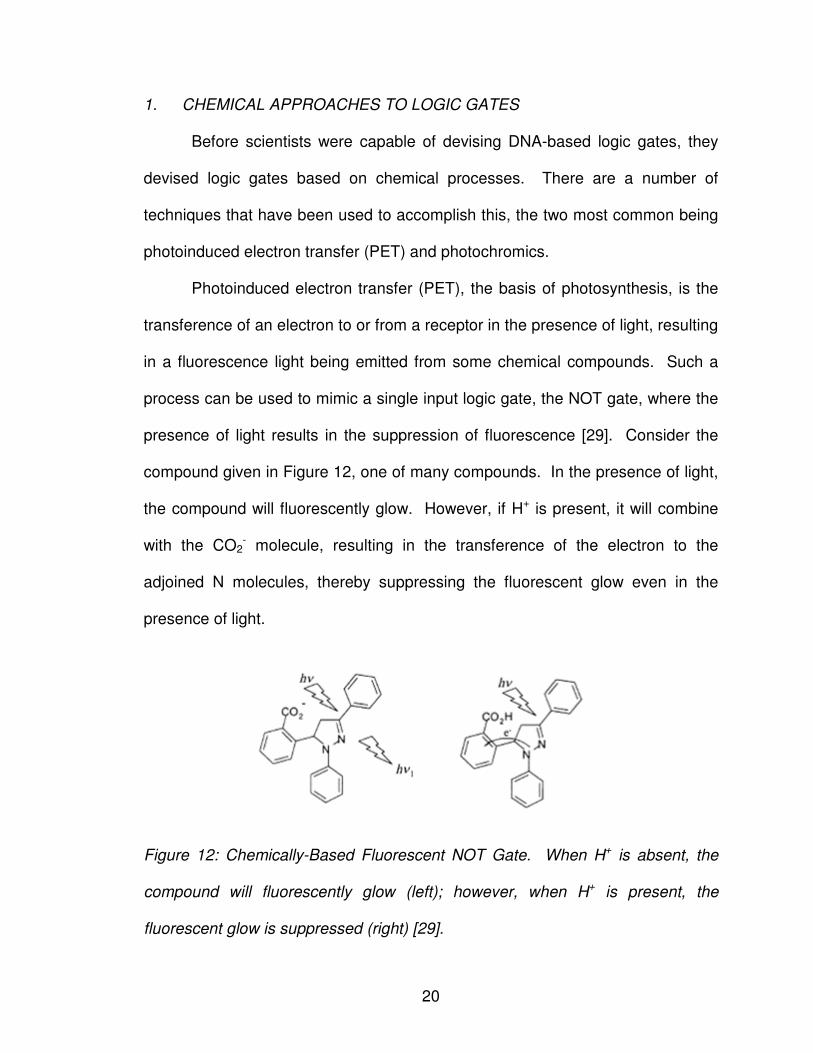
Photoinduced electron transfer (PET), the basis of photosynthesis, is the
transference of an electron to or from a receptor in the presence of light, resulting
in a fluorescence light being emitted from some chemical compounds. Such a
process can be used to mimic a single input logic gate, the NOT gate, where the
presence of light results in the suppression of fluorescence [29]. Consider the
compound given in Figure 12, one of many compounds. In the presence of light,
the compound will fluorescently glow. However, if H+ is present, it will combine
with the CO2- molecule, resulting in the transference of the electron to the
adjoined N molecules, thereby suppressing the fluorescent glow even in the
presence of light.
Figure 12: Chemically-Based Fluorescent NOT Gate. When H+ is absent, the
compound will fluorescently glow (left); however, when H+ is present, the
fluorescent glow is suppressed (right) [29].
21
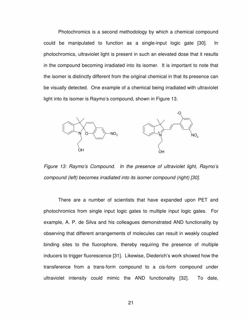
Photochromics is a second methodology by which a chemical compound
could be manipulated to function as a single-input logic gate [30]. In
photochromics, ultraviolet light is present in such an elevated dose that it results
in the compound becoming irradiated into its isomer. It is important to note that
the isomer is distinctly different from the original chemical in that its presence can
be visually detected. One example of a chemical being irradiated with ultraviolet
light into its isomer is Raymo’s compound, shown in Figure 13.
Figure 13: Raymo’s Compound. In the presence of ultraviolet light, Raymo’s
compound (left) becomes irradiated into its isomer compound (right) [30].
There are a number of scientists that have expanded upon PET and
photochromics from single input logic gates to multiple input logic gates. For
example, A. P. de Silva and his colleagues demonstrated AND functionality by
observing that different arrangements of molecules can result in weakly coupled
binding sites to the fluorophore, thereby requiring the presence of multiple
inducers to trigger fluorescence [31]. Likewise, Diederich’s work showed how the
transference from a trans-form compound to a cis-form compound under
ultraviolet intensity could mimic the AND functionality [32]. To date,
22
advancements in chemically–based logic gates have been shown to demonstrate
all logic gate functionality – AND, OR, NOT, NAND, NOR, XOR, XNOT, and
INHIBIT [33-38]. However, despite these advancements, chemically–based logic
gates are continuously inhibited by the lack of homogeneity between gate input
and output, a drawback that plagues a multitude of DNA-based logic gates
methodologies as well.
2. DNA-BASED LOGIC GATES
While Feynman is credited for hypothesizing the development of computer
components comprised of biological components, it is generally accepted that the
1994 publication by Leonard Adleman, “Molecular Computation of Solutions to
Combinatorial Problem,” is the first “proof-of-principle” in which biological
components were experimentally proven to be capable of computation within a
wet-lab setting [39]. In his publication, Adleman solved the Hamiltonian Path
Problem (HPP) with seven nodes in a brute force fashion by biologically
representing all possible paths, then systematically eliminating all invalid paths.
(A detailed explanation is provided in Section 4.2).
In 1995, Richard Lipton expanded upon Adleman’s proof when he
illustrated how Adleman’s approach could be modified to solve other NP
problems. Lipton’s publication, “DNA Solution of Hard Computational Problems,”
demonstrates how the expanded proof could be used to solve the satisfiabilty
problem (SAT) using a similar approach [40]. Lipton’s expanded algorithm was
23
quickly followed by DNA-based algorithms to solve other NP-Hard and NP-
Complete problems [41-50].
2.1 DNA Computation as a SAT Problem
Computation is not limited to searching the problem space for a valid
solution; computation can also be defined as processing a given set of inputs to
yield some dependent output. Recognizing this, Dan Boneh and his colleagues
made an initial step towards computing logic gates by reformulating the problem
as a SAT problem [51]. As such, they could then apply Adleman’s methodology
to solve logic gates as a search function to find the set of inputs resulting in the
function evaluating true.
Boneh et al. define a DNA strand as a sequence α1 … αk over the
alphabet {A, C, G, T}. Their model is comprised of five valid operations:
1. Short sequences of at least 20 bases can be duplicated on a large
scale.
2. Complementary strands of single sequences can be formed
through the annealing process.
3. Sequences matching some given pattern can be extracted from the
test tube.
4. Detection enables one to determine if there are any sequences in
the test tube.
5. Amplification enables all sequences contained within the test tube
to be duplicated.
24
All computations start with one fixed test tube that contains all possible
combinations of inputs. For example, to evaluate an AND logic gate with two
possible inputs, there would be sixteen unique DNA strands contained within the
test tube: four possible values per base for two bases, or 42 = 16 unique strands
(Table 2).
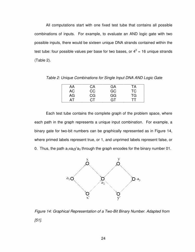
Table 2: Unique Combinations for Single Input DNA AND Logic Gate
AA CA GA TA AC CC GC TC AG CG GG TG AT CT GT TT
Each test tube contains the complete graph of the problem space, where
each path in the graph represents a unique input combination. For example, a
binary gate for two-bit numbers can be graphically represented as in Figure 14,
where primed labels represent true, or 1, and unprimed labels represent false, or
0. Thus, the path a1xa2y’a3 through the graph encodes for the binary number 01.
Figure 14: Graphical Representation of a Two-Bit Binary Number. Adapted from
[51].
25
To evaluate the function to determine the set of inputs that solve the
Boolean logic gates, complementary strands are added to bind two vertices if the
logic function evaluates to true for the set of inputs. For example, if the SAT
problem was to imitate an AND gate, the only valid binary input sequence is 11.
Thus, the ending half of the complementary sequence to x is concatenated with
the beginning half of the complementary sequence to y, thereby creating a
“junction” that binds the two edges together as a valid path. Sequences that lack
the junction (i.e. are single-stranded sequences) are considered invalid solutions
and disregarded. Any double-stranded sequences detected within the solution
are considered valid solutions to the SAT problem.
Using this methodology, any combination of Boolean logic gates that can
be represented as a SAT problem of n variables and m clauses can be evaluated
with at most m intermediary extraction steps and one concluding detection step.
Thus, the time complexity of the Boneh et al. evaluation methodology is
proportional to the size of the Boolean circuit in terms of logic gates.
2.2 DNA Computation Through Site Directed Mutagenesis
One major limitation of the Boneh et al. methodology is the static nature of
the search space. Every computation begins with the same set of initial values,
then one experimentally searches for the subset of valid solutions, if any, that
exist within the test tube for the given problem space. As a result, Donald
Beaver proposed a new technique formulated on the idea of site-directed
mutagenesis of the DNA sequence [52]. In his publication, “A Universal
26
Molecular Computer,” Beaver compares DNA strands to the tape of a Turing
machine – the DNA strand is a linear sequence that stores information over a
finite alphabet.
A Turing machine is a computational machine that consists of four primary
components [53]:
1. Tape segmented into individual cells that stores some input value.
2. Head that reads symbols from the tape and writes the
corresponding output back onto the tape.
3. Table that defines the actions or instructions that are performed
given the current state of the machine and the current input value
read from the tape.
4. State register that stores the current state of the Turing table.
As the head consecutively processes the input values stored on the tape
according to the set of instructions stored in the table for the current state of the
machine, the head may write over a given cell value with a new value, then shift
to the adjacent cell to the left or to the right, depending on the instruction set.
While there is a finite alphabet, a finite set of states, and a finite set of
instructions, there is infinite amount of tape, thus enabling the Turing machine to
have, in theory, storage abilities.
Beaver believed that one could biologically mimic the Turing machine
functionality. Just as the Turing machine alters the contents of a given cell based
on the current input conditions, Beaver hypothesized that one could mutate a
given DNA sequence at a predefined location to mimic the transitional table of
27
the Turing machine. Each mutation of the DNA sequence directly corresponds to
implementing one transitional state on the Turing machine.
Consider the mutation of the sequence αXβ into αYβ. First, the original
sequence must be denatured into its single-stranded representation. Once this is
complete, the single-stranded sequence is mixed with the complementary
sequences of the desired sequence, in this case α’Y’β’. After cooling, the original
sequence αXβ will bond with the complementary sequence α’Y’β’ at the α and β
locations, but will remain unaligned at the overlapping X and Y’ locations.
Finally, duplicating the sequences will result in the formation of the desired αYβ
sequence.
While in theory this approach seems plausible, it is critical that one
recognizes the impeding assumptions of the model. First, the α and β
sequences must be uniquely represented at the cleavage site, otherwise the
sequence will be inadvertently cleaved at undesirable locations. Second, the
desired αYβ will be created, but must be extracted from the test tube containing
other sequences, including αXβ, α’X’β’, and α’Y’β’. Finally, this methodology is
highly susceptible to mutations induced by undesirable external stimuli, and as
such, could result in invalid sequences being devised. As such, some are
skeptical as to the feasibility of this approach [54].
2.3 Experimental Verification of DNA Computation
In 1996, Mitsunori Ogihara and Animesh Ray simulated a DNA-Based
Boolean circuit and experimentally verified their methodology [54]. Prior to their
28
work, DNA computation was limited to searching the problem space for a valid
solution. Ogihara and Ray experimentally verified that DNA computation could
be expanded to be a process by which a given set of inputs yield some
dependent output.
Ogihara and Ray’s methodology is based on appending sequences
together when a truth condition is processed. For each gate within the circuit, a
given DNA sequence σ of length L is assigned such that after evaluation of
inputs, the presence of σ indicates that the given gate evaluates to 1, while its
absence indicates that the gate evaluates to 0. In other words, the DNA
sequence σ is strategically designed as a “linker” between two valid inputs that
correspond to a true output. To simulate the Boolean circuit, this “linker” is
poured for each connected gate and its corresponding inputs such that a gate will
append the corresponding σ if and only if the input combinations logically result
in the gate evaluating true.
For example, for an AND gate to evaluate true, both inputs must also be
true, resulting in a single linker being added to the test tube of input mixture. If
only one of the inputs evaluates true, the corresponding linker will not be able to
bind the two DNA sequences because they are not complementary to the linker
sequence. Conversely, if both inputs have a corresponding true value, the linker
will be able to successfully bind the two sequences, thereby creating at least one
copy of a DNA sequence of length 2L.
Similarly, for an OR gate to evaluate true, only one of the inputs must be
true. Thus, there are three linker sequences that must be added to the test tube
29
of input mixture – (1) both inputs evaluate to true, (2) the first input evaluates to
true and the second input evaluates to false, and (3) the first input evaluates to
false and the second input evaluates to true. Thus, any of these combinations
that are present will result in the OR gate evaluating true and producing a
sequence of length 2L.
It is important to note that the corresponding output length 2L directly
corresponds to the two inputs required for both of this logical gates. Expansion
of the logic gates will require an adjustment to the expected length of the output
for a truth output evaluation. For example, an AND gate with three inputs will
require that one observe an output length of 3L for the gate to accurately reflect a
truth output evaluation.
Similar to the DNA computation design by Boneh et al., any combination
of Boolean circuits can be evaluated in time complexity proportional to the size of
the Boolean circuit in terms of the number of logic gates included. However,
unlike other existing publications, Ogihara and Ray experimentally verified their
methodology by computing two OR gates and one AND gate.
2.4 Reducing Time Complexity to Depth of Circuit
In 1998, DNA computation achieved yet another breakthrough; Martyn
Amos and Paul Dunne were able to devise a DNA simulation of Boolean circuits
with a reduced time complexity; the time complexity could be reduced from the
size of the circuit to the depth of the circuit, or the length of the longest directed
path from an input to an output gate [55]. This reduced complexity marks a
30
significant step towards utilizing the parallelism of biomolecular systems in the
evaluation of Boolean circuits. To demonstrate the validity of their methodology,
Amos and Dunne simulate a NAND gate, as it has been proven to be a self-
contained complete basis [56-58].
Amos and Dunne begin by modeling the n-input, m-output Boolean
network as a directed acyclic graph, S(V,E), where the set of vertices V is the
union of inputs into the network, xn, and the gates within the network, gm. The
method begins by combining into the first tube unique strings of fixed length L for
all inputs with the value one. This tube will serve as the input tube for the
proceeding level gates.
For each corresponding level in the circuit, two test tubes are created –
one containing sequences that uniquely represent each gate at the given level
and one containing sequences that uniquely represent the output of the gate as
the serial combination of the two inputs and single output. Proceeding gates with
inputs m and n from the previous level gates will contain complementary
subsequences to the outputs of the respective gates. Thus, by combining the
output test tube of the previous level with the input test tube of the current level,
one forms aligned sequences wherein the presence of a defined output
sequence is indicative of a truth output evaluation. In other words, one is able to
determine the output of the gate by observing if its representative sequence is
present or not; sequences that are present evaluate to one while those absent
evaluate to zero. Output sequences are then cleaved from its corresponding two
31
input sequences to serve as inputs into the test tube corresponding to the
proceeding level gates.
As one can see, Amos and Dunne were able to devise a DNA simulation
of Boolean circuits that could process all gates at a given level in parallel rather
than having to process each gate individually. As such, they were able to
successfully reduce the number of repetitions required from the number of gates
in the circuit, or its size, to the number of gates in the longest path through the
circuit, or its depth.
2.5 In-vivo Computation: Moving Computation Inside of the Cell
Since Adleman’s first “proof-of-principle,” scientists were able to
biologically design brute force computational search, theorize several methods
by which to simulate computational processes, experimentally validate or
invalidate some of these results in a wet lab, and begin to exploit the parallelism
of biomolecular systems in logic gate design. However, no scientist had been
able to implement genetic computation in-vivo, or within a living organism.
In 2002, Ron Weiss and Subhayu Basu were able to successfully
accomplish in-vivo logic gates within an Escherichia coli (E.coli) bacterial host
through genetic process engineering – a process by which one modifies the DNA
encoding of a target element until circuits of sizeable complexity can be reliably
constructed [59]. Their publication, “The Device Physics of Cellular Logic Gates,”
demonstrates how one could mimic the INVERT and IMPLIES logic gates by
monitoring the mRNA concentration of a particular operon.
32
To emulate the INVERT function, Weiss and Basu examined the lac
operon [6]. The lac operon regulates messenger RNA (mRNA) that controls the
group of genes that metabolizes lactose into glucose and galactose. When
mRNA is absent, the lac operon produces the mRNA to create β-galactosidase to
metabolize lactose. Conversely, when mRNA is present, the lac operon is
inhibited from producing the β-galactosidase mRNA. Thus, the presence of the
input mRNA negates the presence of the output mRNA.
The IMPLIES function is a directional condition that states if the first is
true, then the second must also be true. It is important to note that if the first is
false, then one cannot make any claims to the state of the second condition.
Likewise, the directionality prevents one from determining the state of the first
given the state of the second. To expand the lac operon to mimic the IMPLIES
function, one introduces the lac repressor. When the repressor is present, the
lac operon will not produce β-galactosidase mRNA. When the repressor is
absent, the lac operon will function as the INVERT function described above.
In order for this process to be considered computation, it is important that
the process be able to be externally controlled. To accomplish this, Weiss and
Basu inserted a copy of the lac operon into a plasmid vector that fluorescently
glows when β-galactosidase is present. Thus, the scientists could control the
circuit by controlling the presence of the IPTG, or an inducer for the lac operon,
then observe its state by the presence or absence of the fluorescence.
Additionally, Weiss and Basu further expand on their research by
demonstrating how the lac operon could be genetically altered to achieve more
33
or less sensitivity to various external stimuli. They theorized that such
alternations could allow one to alter mismatched logic gates to achieve the
desired logic functionality.
2.6 From Logic Gates to Logic Circuits
In December 2006, Seelig et al. utilize a nucleic acid logic gate design to
enable large circuits to be reliably constructed [28]. While several prior
publications depicted different methodologies by which biomolecular components
could be manipulated to emulate logic gate functionality, none could be reliably
assembled in order to create large circuits. The publication by Seelig et al.
illustrates how signal restoration, amplification, feedback, and cascading can be
incorporated into their circuit design.
Short oligonucleotide strands are used as inputs and outputs to the logic
gates, with their corresponding logical value of zero or one indicated by the low
and high concentrations of sequences present, respectively. By maintaining
homogeneity between the input and output sequences, logic gates can be
cascaded together to create large circuits. Additionally, in order to maintain
signal integrity throughout the circuit, threshold gates limit the maximum quantity
of sequences present while amplification gates boost the minimum quantity of
sequences present.
Recognizing that nucleic acid reactions can be induced through their
desire to be double-stranded without an enzyme or ribozyme catalyst, Seelig et
al. designed their gates such that their functionality is entirely dependent on base
34
pairing. Gates are comprised of one or more gate strands that are
complementary to their input strand and a single output strand. Each output
strand of a gate will displace the input strand of the next gate, thereby inducing
computation and enabling serial combination of gates in circuit design.
To demonstrate the practicality of their design, Seelig et al. created a
circuit comprised of eleven AND and OR logic gates. In addition to proving the
functionality of their circuit design, they were able to support its expanded
versatility. First, Seelig et al. showed that it was functional for both RNA and
DNA, as it is dependent upon double-stranded base pairing. Second, their circuit
proved stable even when the temperature was elevated from 25ºC to 37ºC.
Finally, the circuit was resilient to the presence of foreign non-complementary
molecules; mouse brain RNA added in excess concentrations did not affect the
circuit’s functionality.
3. DNA ARITHMETIC
Adleman’s “proof-of-principle” combined with Lipton’s expanded proof to
the satisfiability problem (SAT) sparked immense interest in the practicality of a
DNA computer. While some scientists focused on mimicking the functionality of
logic gates with DNA, others focused on mimicking the functionality of arithmetic
operations. But arithmetic functionality adds an additional level of complication.
Unlike search problems in which the correct solution can be extracted from all
generated solutions, arithmetic requires that only the correct solution be
generated.
35
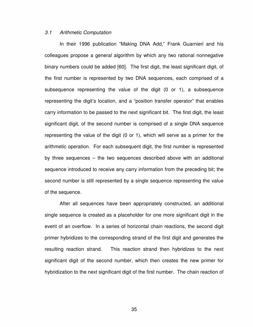
3.1 Arithmetic Computation
In their 1996 publication “Making DNA Add,” Frank Guarnieri and his
colleagues propose a general algorithm by which any two rational nonnegative
binary numbers could be added [60]. The first digit, the least significant digit, of
the first number is represented by two DNA sequences, each comprised of a
subsequence representing the value of the digit (0 or 1), a subsequence
representing the digit’s location, and a “position transfer operator” that enables
carry information to be passed to the next significant bit. The first digit, the least
significant digit, of the second number is comprised of a single DNA sequence
representing the value of the digit (0 or 1), which will serve as a primer for the
arithmetic operation. For each subsequent digit, the first number is represented
by three sequences – the two sequences described above with an additional
sequence introduced to receive any carry information from the preceding bit; the
second number is still represented by a single sequence representing the value
of the sequence.
After all sequences have been appropriately constructed, an additional
single sequence is created as a placeholder for one more significant digit in the
event of an overflow. In a series of horizontal chain reactions, the second digit
primer hybridizes to the corresponding strand of the first digit and generates the
resulting reaction strand. This reaction strand then hybridizes to the next
significant digit of the second number, which then creates the new primer for
hybridization to the next significant digit of the first number. The chain reaction of
36
hybridization is cyclically repeated until all digits in both binary numbers have
been computed.
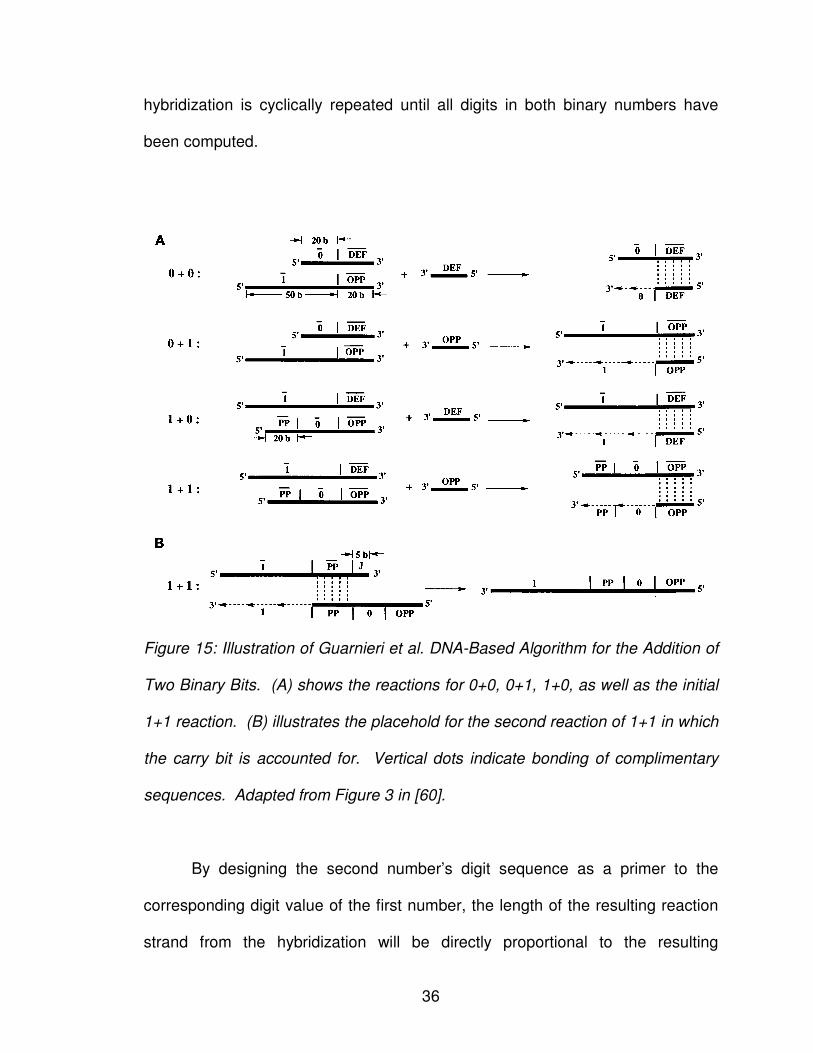
Figure 15: Illustration of Guarnieri et al. DNA-Based Algorithm for the Addition of
Two Binary Bits. (A) shows the reactions for 0+0, 0+1, 1+0, as well as the initial
1+1 reaction. (B) illustrates the placehold for the second reaction of 1+1 in which
the carry bit is accounted for. Vertical dots indicate bonding of complimentary
sequences. Adapted from Figure 3 in [60].
By designing the second number’s digit sequence as a primer to the
corresponding digit value of the first number, the length of the resulting reaction
strand from the hybridization will be directly proportional to the resulting
37
arithmetic value of the solution. For example, the addition of two single digit
binary numbers can result in three possible binary solutions: 0 from the addition
of 0 and 0, 1 from the addition of 0 and 1 or 1 and 0, and 10 from the addition of
1 and 1. Using 20-base DNA sequences to represent each digit and the chain
hybridization technique proposed by Guarnieri and his colleagues, DNA addition
results in a 40-base solution to represent 0, a 70-base solution to represent 1,
and a 110-base solution to represent 10.
3.2 The Subset-Sum Problem
In 2004, Weng-Long Chang and his colleagues expanded the work in
DNA arithmetic by developing an n-bit parallel adder [61]. Their publication,
“Molecular Solutions for the Subset-Sum Problem on DNA-Based
Supercomputing,” introduces two DNA-based algorithms – one for an n-bit
parallel adder and one for an n-bit parallel comparator – that are used to solve
the subset-sum problem. The subset-sum problem is an NP-complete special
case of the knapsack problem in which one must determine if a given non-empty
set of integers S, or any subset, exactly sums to some given integer s [62]. Their
proposed algorithms automate the biological functions presented in Adleman’s
“proof-of-principle” publication within a sticker-based model.
The Chang et al. algorithms begin by generating unique DNA sequences
representing all possible subsets of the problem. Each subset is represented by
a q-bit binary number that corresponds to the subset and an n-bit number that
corresponds to the size of an element in the initial set, where each bit is encoded
38
with a 15-base DNA sequence. Each subset sum value is then calculated in
parallel operations and the final solution value s is searched for among the
resulting solutions. Since every subset is represented, intermediary sums can be
ignored as they are already considered. Additionally, since every subset has
been considered, if the solution s is not found, then no valid solution exists for the
given decision problem.
In addition to solving the subset-sum problem utilizing DNA, Chang et al.
presented algorithms for determining the number of tubes, the length of the
longest DNA strand, the number of DNA strands, and the number of biological
operations required to solve the subset-sum problem using their proposed
automated bench-top approach. Furthermore, Chang et al. recognized the
underlying factor that all multiplication operations are repetitive addition
problems, and as such, can also be solved with their proposed algorithm.
3.3 Arithmetic Working Backwards: Factoring Integers
In the follow-up paper in 2005, entitled “Fast Parallel Molecular Algorithms
for DNA-Based Computation: Factoring Integers,” Chang et al. expanded upon
their algorithms to propose a DNA-Based parallel subtractor, comparator, and
modular arithmetic [63]. These additional algorithms are then utilized with the
biological operations and sticker model approach in their previous publication to
show how one can factor a large integer comprised of two prime numbers.
The ability to factor a large integer into its two corresponding prime
numbers is of particular interest in relation to the RSA public-key encryption
39
algorithm. RSA security is based on the mathematical complexity of two
randomly selected large prime numbers. A given user will select two randomly
large prime numbers, p and q, which are multiplied together to create n. Using n,
one selects a relative prime e odd number calculated as (p-1)*(q-1). The
combination of n and e comprise the public key P of the algorithm. The private
key, S, is comprised of n and d, where d is the multiplicative inverse of the odd
integer e. This approach to secure key encryption has been successful because
no computational algorithm to date has been able to factor n into the
corresponding large p and q prime numbers in a reasonable time span. A DNA
algorithm that can successful factor a large integer into its two corresponding
prime numbers negates the security benefits of the algorithm.
40
CHAPTER IV
DNA MEDIA STORAGE
DNA-based circuit design is an area of research in which traditional
silicon-based technologies are replaced with naturally occurring phenomena
taken from biochemistry and molecular biology. Despite advancements in the
design of a molecular logic gates (see Chapter III: Designing Biological Logic
Gates), DNA computing has not yet become a commonly accepted practice.
However, advancements are continually being discovered that are evolving the
field of DNA computing. A novel approach in which DNA could be used as a
means of storing files is introduced. Through the use of multiple sequence
alignment combined with intelligent heuristics, the most probabilistic file contents
can be determined with minimal errors.
1. DNA REPRESENTATION OF DIGITAL INFORMATION
Computer scientists have long used the notion of a binary bit to represent
digital information, wherein 1 indicates that the element is present and 0
indicates that the given element is absent [53]. Combining a series of binary bits
enables more states to be represented; a two-bit binary sequence can represent
four possible states – 00, 01, 10, 11 – where each element represents an
41
associated state in the problem. In this same manner, geneticists represent the
four possible DNA states with a quaternary alphabet, using the symbols A, C, G,
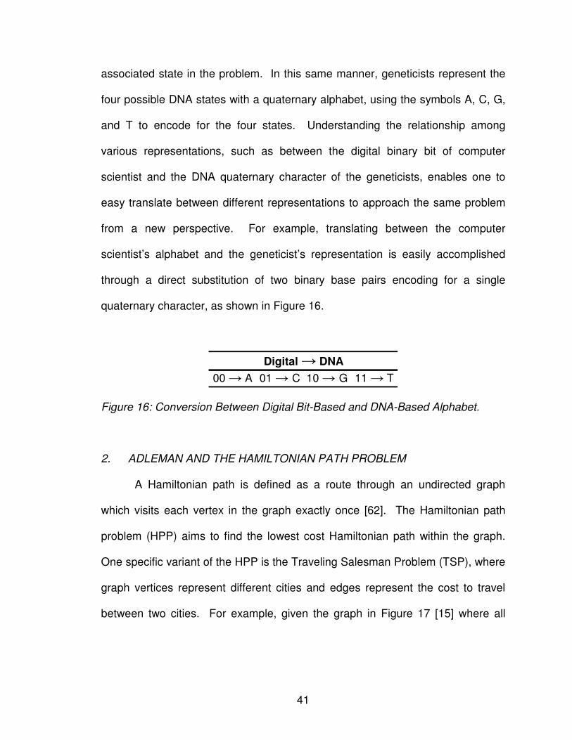
and T to encode for the four states. Understanding the relationship among
various representations, such as between the digital binary bit of computer
scientist and the DNA quaternary character of the geneticists, enables one to
easy translate between different representations to approach the same problem
from a new perspective. For example, translating between the computer
scientist’s alphabet and the geneticist’s representation is easily accomplished
through a direct substitution of two binary base pairs encoding for a single
quaternary character, as shown in Figure 16.
00 → A 01 → C 10 → G 11 → T
Digital → DNA
Figure 16: Conversion Between Digital Bit-Based and DNA-Based Alphabet.
2. ADLEMAN AND THE HAMILTONIAN PATH PROBLEM
A Hamiltonian path is defined as a route through an undirected graph
which visits each vertex in the graph exactly once [62]. The Hamiltonian path
problem (HPP) aims to find the lowest cost Hamiltonian path within the graph.
One specific variant of the HPP is the Traveling Salesman Problem (TSP), where
graph vertices represent different cities and edges represent the cost to travel
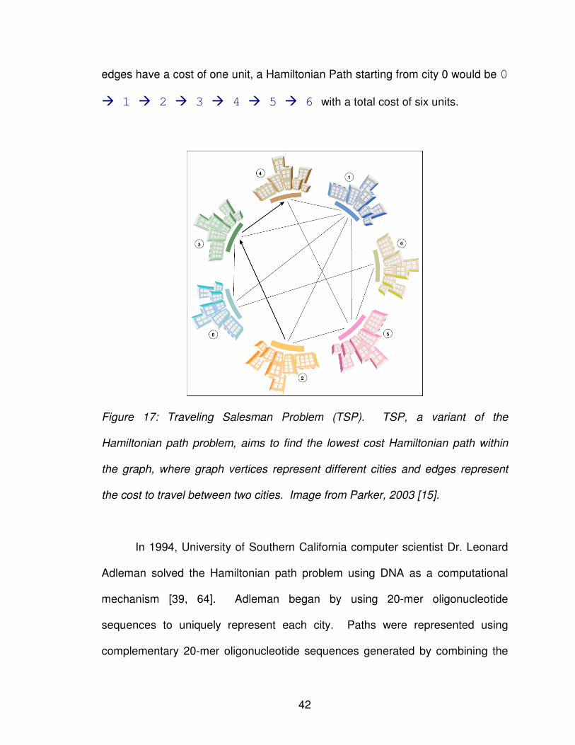
between two cities. For example, given the graph in Figure 17 [15] where all
42
edges have a cost of one unit, a Hamiltonian Path starting from city 0 would be 0
� 1 � 2 � 3 � 4 � 5 � 6 with a total cost of six units.
Figure 17: Traveling Salesman Problem (TSP). TSP, a variant of the
Hamiltonian path problem, aims to find the lowest cost Hamiltonian path within
the graph, where graph vertices represent different cities and edges represent
the cost to travel between two cities. Image from Parker, 2003 [15].
In 1994, University of Southern California computer scientist Dr. Leonard
Adleman solved the Hamiltonian path problem using DNA as a computational
mechanism [39, 64]. Adleman began by using 20-mer oligonucleotide
sequences to uniquely represent each city. Paths were represented using
complementary 20-mer oligonucleotide sequences generated by combining the
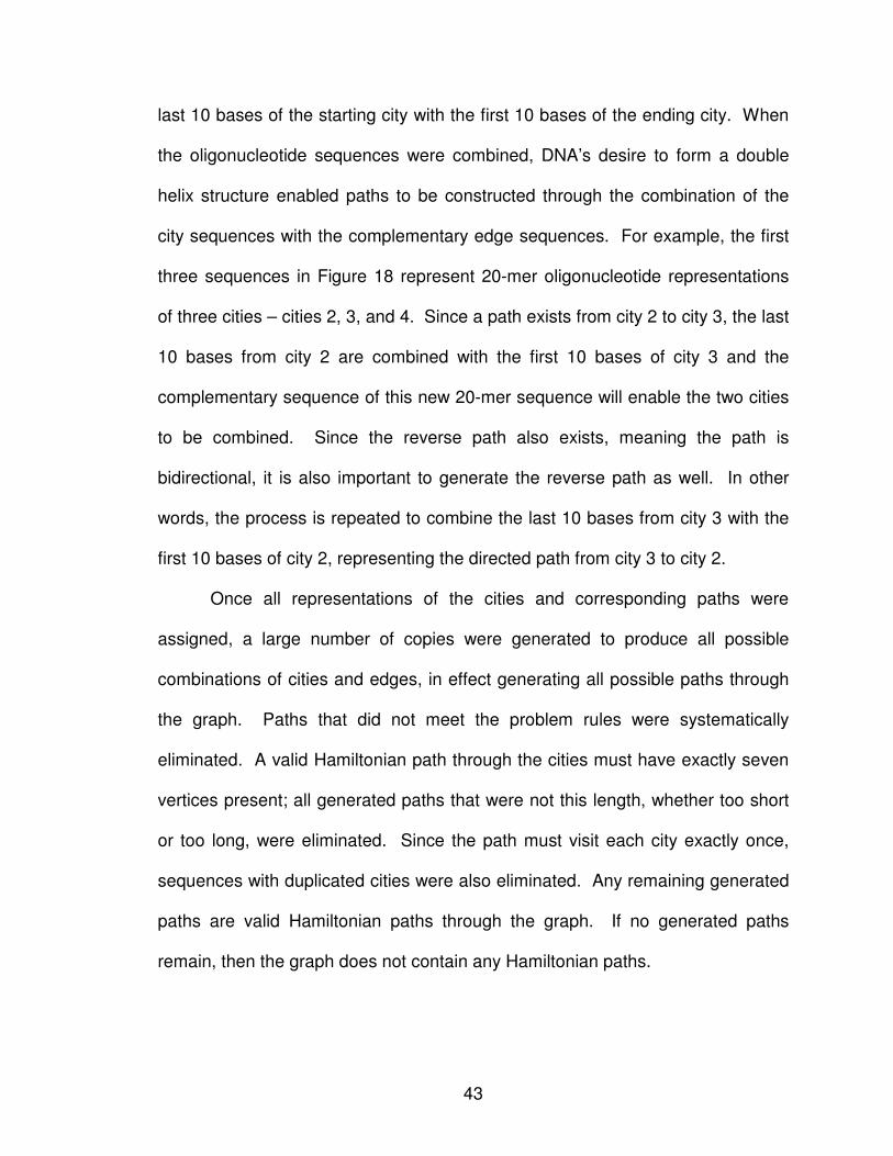
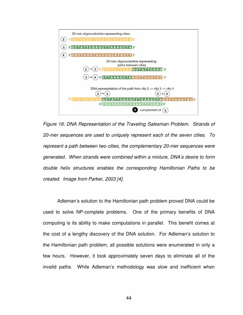
43
last 10 bases of the starting city with the first 10 bases of the ending city. When
the oligonucleotide sequences were combined, DNA’s desire to form a double
helix structure enabled paths to be constructed through the combination of the
city sequences with the complementary edge sequences. For example, the first
three sequences in Figure 18 represent 20-mer oligonucleotide representations
of three cities – cities 2, 3, and 4. Since a path exists from city 2 to city 3, the last
10 bases from city 2 are combined with the first 10 bases of city 3 and the
complementary sequence of this new 20-mer sequence will enable the two cities
to be combined. Since the reverse path also exists, meaning the path is
bidirectional, it is also important to generate the reverse path as well. In other
words, the process is repeated to combine the last 10 bases from city 3 with the
first 10 bases of city 2, representing the directed path from city 3 to city 2.
Once all representations of the cities and corresponding paths were
assigned, a large number of copies were generated to produce all possible
combinations of cities and edges, in effect generating all possible paths through
the graph. Paths that did not meet the problem rules were systematically
eliminated. A valid Hamiltonian path through the cities must have exactly seven
vertices present; all generated paths that were not this length, whether too short
or too long, were eliminated. Since the path must visit each city exactly once,
sequences with duplicated cities were also eliminated. Any remaining generated
paths are valid Hamiltonian paths through the graph. If no generated paths
remain, then the graph does not contain any Hamiltonian paths.
44
Figure 18: DNA Representation of the Traveling Salesman Problem. Strands of
20-mer sequences are used to uniquely represent each of the seven cities. To
represent a path between two cities, the complementary 20-mer sequences were
generated. When strands were combined within a mixture, DNA’s desire to form
double helix structures enables the corresponding Hamiltonian Paths to be
created. Image from Parker, 2003 [4].
Adleman’s solution to the Hamiltonian path problem proved DNA could be
used to solve NP-complete problems. One of the primary benefits of DNA
computing is its ability to make computations in parallel. This benefit comes at
the cost of a lengthy discovery of the DNA solution. For Adleman’s solution to
the Hamiltonian path problem, all possible solutions were enumerated in only a
few hours. However, it took approximately seven days to eliminate all of the
invalid paths. While Adleman’s methodology was slow and inefficient when
45
compared with today’s methodologies, it is still a lengthy process to biologically
find the DNA solutions among a given mixture.
DNA has the ability to store a vast amount of information. Current
methods of data storage require approximately 1012 nm3 of space to store a
single bit, while DNA has the ability to store a single bit in only 1 nm3 [15].
However, DNA representation of problems can be difficult. Adleman represented
each city and edge with a 20-mer sequence to ensure there would be no errors in
his calculations of the Hamiltonian paths. If one were to scale the Hamiltonian
path problem from the original seven cities to two hundred cities, the DNA
required to represent all of the cities and corresponding edges would be greater
than the weight of earth.
Finally, since Adleman’s experiment was limited to only seven cities, he
could represent the cities with distinctly different sequences as to minimize the
number of alignments that would result in solutions that do not exist. However,
as the number of cities increase, it becomes more difficult to uniquely represent
the cities in such a manner as to avoid mismatched alignments. Therefore,
additional error-checking would be required to ensure accurate solutions.
3. USING MULTIPLE SEQUENCE ALIGNMENT IN ERROR REDUCTION
DNA allows for a drastic reduction in storage space per bit compared with
traditional digital computing. As a result, redundant storage capabilities and
parallel processing on the same data are feasible. However, if the storage or
computation results in inconsistencies, determining which are correct and which
46
are not is problematic. The bioinformatics technique of multiple sequence
alignment yields insight into how the issue of data integrity can be solved.
3.1 Multiple sequence alignment
Multiple sequence alignment is the process of finding a representative, or
consensus, model of the similarities between three or more sequences. Like
pairwise sequence alignment, it finds an optimal solution for the model conditions
placed upon it. If conditions are changed, then the model may or may not hold.
For a set of highly conserved sequences, the multiple sequence alignment is
easily seen, even with the naked eye. As sequences diverge, so does the
complexity of finding the best alignment [65].
Multiple sequence alignment begins by finding the optimal pairwise
sequence alignment between each pair of sequences. Once found, there are a
number of approaches used to discover the underlying model. The top three
approaches are progressive [65], iterative [66], and statistical or probabilistic
modeling [67]. Progressive modeling begins with the alignment of the two most
similar sequences and iteratively adds sequences to the alignment in descending
order of similarity. Iterative modeling aligns any pair of similar sequences or set
of sequences, continually clustering until only one group remains.
Finally, statistical or probabilistic modeling selects the ordering of
alignment based on a given statistical or probabilistic model believed to represent
the given set of sequences. Once a multiple sequence alignment is in place, it
can be described using a number of different approaches. The most useful of
47
these represents the alignment as a statistical model, known as a profile Hidden
Markov Model (HMM) [68]. HMMs have the power to represent the alignment
through states for insertions, deletions, and matches/mismatches found within
the alignment. For the match/mismatch and insertion states, an associated
emission probability is given to the observed characters for a particular position.
3.2 Multiple Sequence Alignment for Error Reduction
Since multiple sequence alignment is sensitive to sequence similarities, it
can be used to combine the multiple copies of the same file to find the most
probabilistic contents. There are three scenarios that can be discovered: (1)
areas completely conserved among all of the sequences, (2) areas highly
conserved among the sequences, and (3) areas not conserved among the
sequences. Each of these scenarios directly corresponds with the level of error
within the region.
First, consider areas that are completely conserved among all of the
sequences. In this case, no mutations have occurred in any of the file copies.
Since the region is an exact clone of all other copies, there are no discrepancies
introduced and as such, the region is completely 100% free of errors. For highly
conserved areas, discrepancies indicate potential areas that have been
introduced. Since a multitude of copies have been stored, then it is probable that
the majority of sequences will be highly correlated. Thus, the emission
properties of the associated Hidden Markov Model state will clearly indicate
which one of the bases is most probable of being emitted as it will have a
48
significantly higher emission over the remaining bases. It is important to note
that pseudocounts should not be introduced within the Hidden Markov Model, as
they will skew the emissions of the state.
Finally, consider areas that are not conserved among the sequences. It
may not be possible to determine the most probabilistic emission because a
significant number of discrepancies have been introduced into the region. Since
there can be no determination as to what the sequence was originally, this region
represents the system state of irrecoverable errors. In such circumstances, there
are a number of external alternatives to be considered. An artificial intelligent
agent could be introduced to make the final determination of the state.
Conversely, all of the represented sequences could be presented to the end user
to make the final determination as to what were the original contents of the file.
3.3 Improving the Multiple Sequence Alignment
The genetic code allows for a three-base nucleotide sequence (codon) to
encode for one of twenty amino acids within an organism, as discussed in
Chapter II: Introduction To Biology For The Computer Scientist. Consequently,
alignment of the translated amino acid sequences has a greater probability of
defining more highly conserved regions that may be indeterminate at a DNA
sequence level. Alignment of regions of low conservation can potentially be
improved by aligning the corresponding translated amino acid sequences.
While increased accuracy is possible, it comes at a cost of a dramatic increase in
the computational time required to find the alignment. As discussed in Chapter
49
II: Introduction to Biology for the Computer Scientist, translation of a DNA
sequence into its corresponding amino acid sequence results in six possible
sequences.
Thus, the pairwise alignment between two nucleotide sequences results in
thirty-six combinations from aligning each of the six amino acid sequences
translated from the first DNA sequence with each of the six amino acid
sequences translated from the second DNA sequence. The pairwise alignment
with the highest score is then deemed to be the best alignment.
3.4 Heuristic Improvements of the Algorithm
Knowing the aligned sequences are very similar, if not identical, a number
of heuristics can be applied to reduce the computational, storage, and time
complexity required for multiple sequence alignment. Continuing with the
discussion of the storage of a file, it is reasonable to assume that the majority of
sequences being aligned will be of the same length within a given threshold.
Since a file will not produce or reduce the amount of information contained within
it without external stimuli, one can quickly eliminate sequences disproportionately
longer or shorter than majority of sequences being aligned.
Sequences are highly similar, meaning the alignment will probabilistically
follow the diagonal of the dynamic programming alignment matrix [69, 70]. Thus,
one can reduce the computational and storage complexity by performing a
bounded alignment in which only cells within a given threshold above and below
the diagonal of the dynamic programming alignment matrix are calculated. The
50
appropriate threshold is dependent on the application, however for any sequence
set of substantial length, it is reasonable to assume that the threshold could be
set between 5-10% and still produce highly accurate results.
To further reduce these complexities, an intelligent agent could retain
probabilities of identical alignments without requiring actual storage of the
alignments. Specifically, if two or more sequences are identical, it is inefficient to
store the alignment, as the highest pairwise alignment is an exact copy of itself.
However, the frequencies of the identical sequences must be retained for the
Hidden Markov Model emissions to be accurate. If these frequencies are not
retained, then discrepancies in the alignment with be emphasized as the
frequency of the dominate character is decreased.
4. DISCUSSION
Duplicate copies of a file must be stored for accurate information retrieval.
Figure 19 shows eight generated strings representing encoding sequences of a
file. Changes are introduced within the sequences to represent mutations that
could occur within a biological environment.
Alignment of the nucleotide sequences in Figure 20 reveals completely
conserved, highly conserved, and indeterminate states. Completely conserved
states are indicated with bold, uppercase text; highly conserved states are
indicated with lowercase text; indeterminate states are indicated with a solid
circle. Using eight nucleotide sequences results in only fourteen of the twenty-
seven bases being completely conserved, or 51.9%. While only one state is
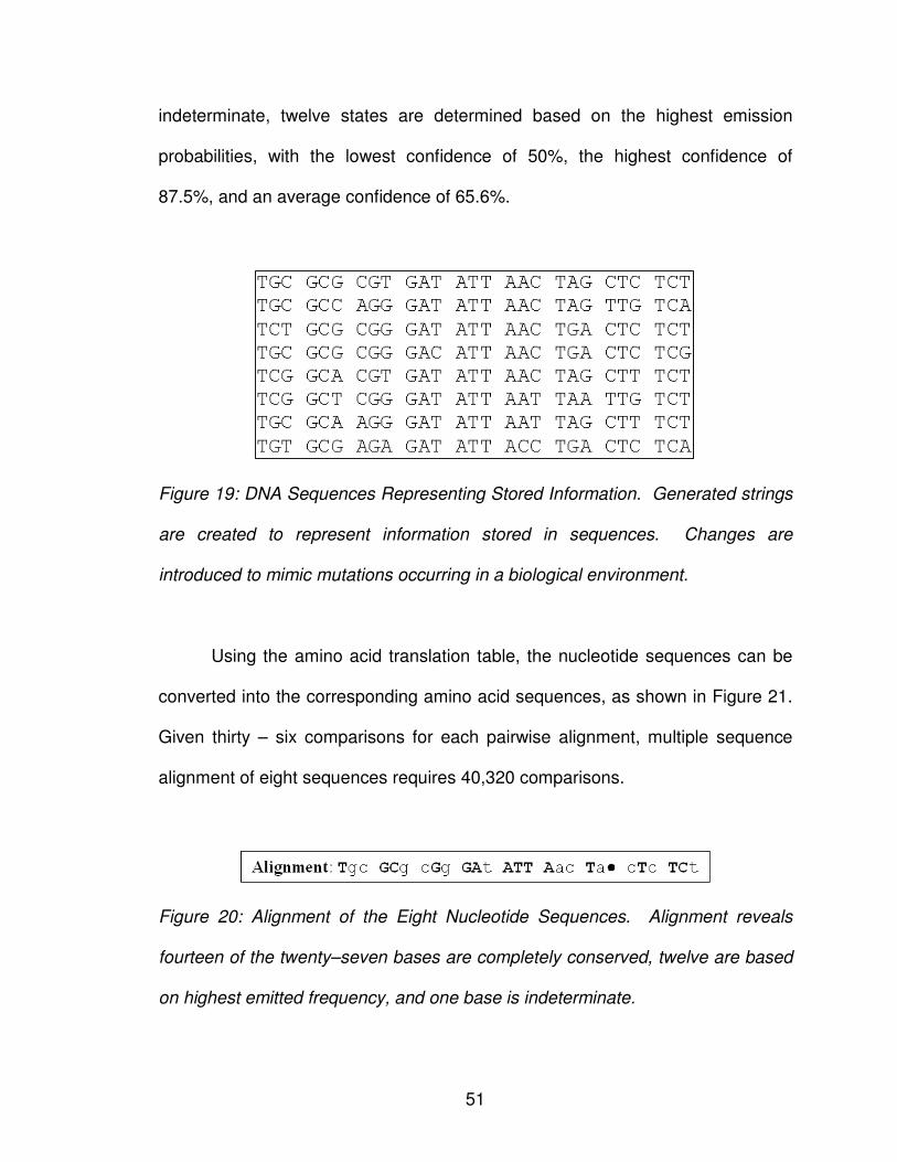
51
indeterminate, twelve states are determined based on the highest emission
probabilities, with the lowest confidence of 50%, the highest confidence of
87.5%, and an average confidence of 65.6%.
Figure 19: DNA Sequences Representing Stored Information. Generated strings
are created to represent information stored in sequences. Changes are
introduced to mimic mutations occurring in a biological environment.
Using the amino acid translation table, the nucleotide sequences can be
converted into the corresponding amino acid sequences, as shown in Figure 21.
Given thirty – six comparisons for each pairwise alignment, multiple sequence
alignment of eight sequences requires 40,320 comparisons.
Figure 20: Alignment of the Eight Nucleotide Sequences. Alignment reveals
fourteen of the twenty–seven bases are completely conserved, twelve are based
on highest emitted frequency, and one base is indeterminate.
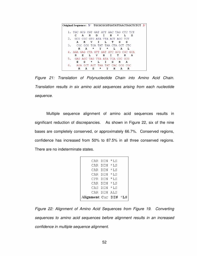
52
Figure 21: Translation of Polynucleotide Chain into Amino Acid Chain.
Translation results in six amino acid sequences arising from each nucleotide
sequence.
Multiple sequence alignment of amino acid sequences results in
significant reduction of discrepancies. As shown in Figure 22, six of the nine
bases are completely conserved, or approximately 66.7%. Conserved regions,
confidence has increased from 50% to 87.5% in all three conserved regions.
There are no indeterminate states.
Figure 22: Alignment of Amino Acid Sequences from Figure 19. Converting
sequences to amino acid sequences before alignment results in an increased
confidence in multiple sequence alignment.
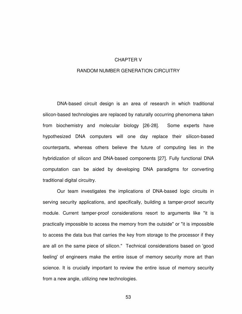
53
CHAPTER V
RANDOM NUMBER GENERATION CIRCUITRY
DNA-based circuit design is an area of research in which traditional
silicon-based technologies are replaced by naturally occurring phenomena taken
from biochemistry and molecular biology [26-28]. Some experts have
hypothesized DNA computers will one day replace their silicon-based
counterparts, whereas others believe the future of computing lies in the
hybridization of silicon and DNA-based components [27]. Fully functional DNA
computation can be aided by developing DNA paradigms for converting
traditional digital circuitry.
Our team investigates the implications of DNA-based logic circuits in
serving security applications, and specifically, building a tamper-proof security
module. Current tamper-proof considerations resort to arguments like "it is
practically impossible to access the memory from the outside" or "it is impossible
to access the data bus that carries the key from storage to the processor if they
are all on the same piece of silicon." Technical considerations based on 'good
feeling' of engineers make the entire issue of memory security more art than
science. It is crucially important to review the entire issue of memory security
from a new angle, utilizing new technologies.
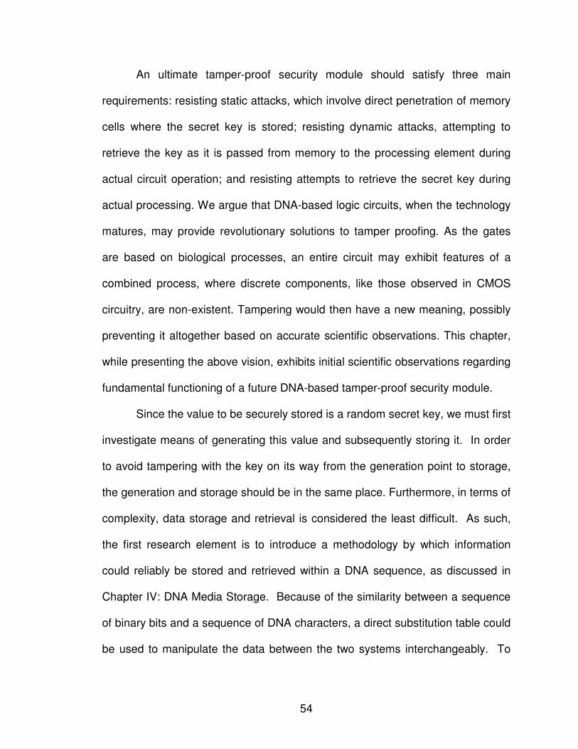
54
An ultimate tamper-proof security module should satisfy three main
requirements: resisting static attacks, which involve direct penetration of memory
cells where the secret key is stored; resisting dynamic attacks, attempting to
retrieve the key as it is passed from memory to the processing element during
actual circuit operation; and resisting attempts to retrieve the secret key during
actual processing. We argue that DNA-based logic circuits, when the technology
matures, may provide revolutionary solutions to tamper proofing. As the gates
are based on biological processes, an entire circuit may exhibit features of a
combined process, where discrete components, like those observed in CMOS
circuitry, are non-existent. Tampering would then have a new meaning, possibly
preventing it altogether based on accurate scientific observations. This chapter,
while presenting the above vision, exhibits initial scientific observations regarding
fundamental functioning of a future DNA-based tamper-proof security module.
Since the value to be securely stored is a random secret key, we must first
investigate means of generating this value and subsequently storing it. In order
to avoid tampering with the key on its way from the generation point to storage,
the generation and storage should be in the same place. Furthermore, in terms of
complexity, data storage and retrieval is considered the least difficult. As such,
the first research element is to introduce a methodology by which information
could reliably be stored and retrieved within a DNA sequence, as discussed in
Chapter IV: DNA Media Storage. Because of the similarity between a sequence
of binary bits and a sequence of DNA characters, a direct substitution table could
be used to manipulate the data between the two systems interchangeably. To
55
ensure data is accurately retrieved, multiple sequence alignment enables
multiple copies of the same file to find the most probabilistic contents. Like a
parity bit, the multiple sequence alignment can indicate that a possible error has
occurred. However, while a parity bit can only indicate that an error has
occurred, multiple sequence alignment enables the location and type of the
possible error to be determined.
Having shown a methodology by which data can be accurately stored and
retrieved, the next research component toward devising a DNA-based tamper-
proof security module would be to devise a methodology by which one could
generate a secret key within the module. As an initial step, a random number
generation (RNG) circuitry has been developed. Here, we propose that the
secret key, which is actually a random value, be generated by the DNA-based
non-volatile memory that subsequently stores the key. A copy of the generated
key is then made to share with other friendly parties. Security applications
requiring RNG, beside key generation, pertain to nonces (numbers used once),
salts in certain signature schemes, and one-time pads. These are essential
security components. Any current commercial microchip dedicated to security
applications has RNG circuitry and any standard on security applications
includes an RNG chapter.
The remainder of the chapter begins by describing the biological process
by which sequences are synthesized in Section 2. Section 3 defines random
number generation through DNA sequences. Section 4 describes plasmid
vectors, the biological tool by which DNA sequences can be temporarily stored.
56
The random number generation circuitry is discussed in Section 5, followed by
the statistical methods utilized to evaluate randomness for the simulation.
Finally, justification for DNA-Based Random Number Generation is provided in
Section 7.
1. OLIGONUCLEOTIDE SYNTHESIS
Oligonucleotide synthesis is the process in which short sequences of
nucleic acids are produced. There are two primary methods of synthesizing
oligonucleotide sequences – sequential [71] and solid phase synthesis [72].
Sequential synthesis occurs by deprotecting the 5’ phosphate then adding the
phosphoramidites of the desired nucleic acid in sequential order until the
sequence is completed. Sequentially synthesized sequences have a low
tolerance to error, and as such are not suitable for creating sequences greater
than one hundred nucleotide bases in length.
Solid phase synthesis of an oligonucleotide sequence occurs as a five
step process. The 3’ end of the initial nucleotide is bound to a solid support
column. A purified solution of the next nucleic acid is then pumped through the
support column to adhere a single nucleotide base to the bounded sequence.
The remaining solution mixture is then washed out of the support column. The
synthesis process continues until the oligonucleotide sequence is created.
Finally, the completed oligonucleotide sequence is cleaved from the support
column.
57
Regardless of whether the oligonucleotide sequence is created through
sequential or solid phase synthesis, there are four steps to the actual process.
The first step, detritylation, releases the 5’ hydroxyl group of the ending
nucleotide. Then, the phosphate group of the proceeding nucleotide is removed,
enabling the two nucleotides to be bound together. Capping blocks non-reacting
nucleotides from incorrectly synthesizing to the sequence, allowing excess
nucleotides to be washed off. Finally, oxidation allows the two bounded
nucleotides to become permanently stable.
2. RANDOM NUMBER GENERATION WITH DNA
A random number, in its primitive form, is a sequence of digits selected at
random to generate a number within a given range modeling a given distribution.
For example, to generate a random binary number with a range of 0 to 210
following a uniform distribution, one would randomly select either a zero or one
independently for each of the ten bits, with the probability of selecting zero equal
to 50% and the probability of selecting one equal to 50%.
To generate a random DNA sequence following a uniform distribution, one
would randomly select one of four possible characters – A, C, G, T – for each
place in the sequence, with each character having the probability of being
selected equal to 25%. Assigning a 2-bit value to each character, a sequence of
4n characters generates a random number of n bytes.
58
3. PHYSICALLY SYNTHESIZING THE RANDOM NUMBER SEQUENCE
While either method of oligonucleotide synthesis will enable a sequence to
be generated, solid phase synthesis is the most effective method of creating a
random oligonucleotide sequence. The practical application of randomly
assigning a nucleotide to the sequence will simplify the solid phase synthesis
process. Rather than using a purified solution of a single nucleic acid mixture, a
mixture of nucleic acids of a predetermined distribution could be repeatedly
washed through the support column. For example, if a sequence with uniform
distribution of each of the four nucleotides is desired, a mixture containing 25%
A’s, 25% C’s, 25% G’s, and 25% T’s can be created. This solution mixture would
be continuously used, enabling nucleotides to randomly adhere to the sequence
until the desired length is achieved.
It is important to note the simplification of the cleansing process. Solid
phase synthesis requires that one must cleanse the support column of any
residue nucleic acid to prevent one from erroneously adhering to the sequence.
There is no restriction on which nucleotide should adhere to the sequence next,
therefore cleansing residue nucleotides from the support column is not necessary
since all nucleic acid assignments are valid assignments.
4. TEMPORARY STORAGE OF RANDOM NUMBERS
Plasmid vectors are small, circular DNA molecules found in bacteria that
enable inserted DNA gene sequences to be transported between various
organisms [73]. In order to encompass the gene sequence, plasmid vectors are
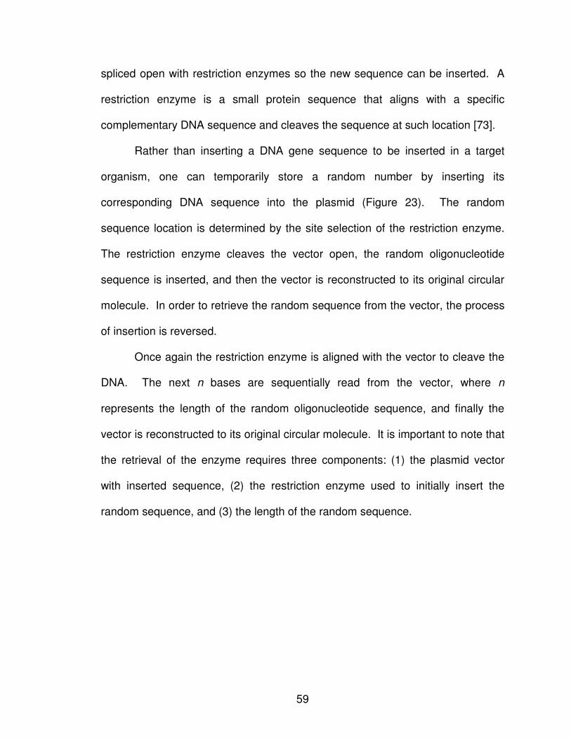
59
spliced open with restriction enzymes so the new sequence can be inserted. A
restriction enzyme is a small protein sequence that aligns with a specific
complementary DNA sequence and cleaves the sequence at such location [73].
Rather than inserting a DNA gene sequence to be inserted in a target
organism, one can temporarily store a random number by inserting its
corresponding DNA sequence into the plasmid (Figure 23). The random
sequence location is determined by the site selection of the restriction enzyme.
The restriction enzyme cleaves the vector open, the random oligonucleotide
sequence is inserted, and then the vector is reconstructed to its original circular
molecule. In order to retrieve the random sequence from the vector, the process
of insertion is reversed.
Once again the restriction enzyme is aligned with the vector to cleave the
DNA. The next n bases are sequentially read from the vector, where n
represents the length of the random oligonucleotide sequence, and finally the
vector is reconstructed to its original circular molecule. It is important to note that
the retrieval of the enzyme requires three components: (1) the plasmid vector
with inserted sequence, (2) the restriction enzyme used to initially insert the
random sequence, and (3) the length of the random sequence.
60
Figure 23. Illustration of the Insertion of Chromosomal DNA into a Plasmid Vector
Cut by a Restriction Enzyme. Image adapted from [74].
5. RANDOM NUMBER GENERATION CIRCUITRY
A random number generation circuit must be capable of creating each
component required. The circuit must be able to create the random sequence,
translate it into the corresponding random number, and output the random
number value.
Once the microfluidic device receives an input signal to generate a
random number, the first task is to create a random oligonucleotide sequence.
Therefore, there must be some renewable mechanism by which each of the four
nucleic acids could be selected as a possible next base. It is envisioned such
mechanism would be comprised of four fluidic wells each containing a
61
fluorescently-labeled pure mixture of one nucleic acid which could be refilled as
quantities became diminished.
A transportation tube would independently pull a specified quantity of each
nucleic acid and deposit into the mixing chamber. The mixing chamber would
combine the four quantities to create the solution mixture. Using solid phase
synthesis, the solution mixture would be poured over a support column to create
the random sequence until a given length is reached.
It is important to note the distribution probability dependence on the
solution mixture. If the sequence generated is to have equal distribution of the
nucleotides over the length of the sequence, then the same solution mixture can
be repeatedly poured over the support column. Since each base should have
equal probability of being one of the four nucleotides, it is critical that the solution
mixture be based on selection with replacement rather than selection without
replacement. Without replacing the adhered nucleotide, the probability of the
given base being selected decreases with each additional sequence bit added.
However, it is important to note that a minute amount of the solution contains an
immense amount of each nucleotide. A quantity of one micro liter contains 5 x
1011 molecules [75]. Thus, removing one nucleotide will still maintain an overall
equal distribution. Therefore, the mixing chamber could combine one micro liter
of each nucleotide solution and continuously pour the solution over the column
until the desired sequence length is reached.
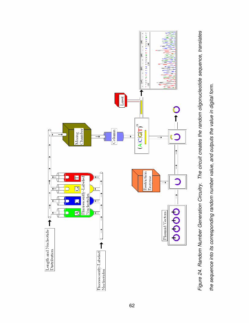
62
Fig
ure
24
. R
an
do
m N
um
be
r G
ene
ratio
n C
ircu
itry
. T
he
circu
it c
rea
tes t
he
ra
nd
om
olig
on
ucle
otid
e s
eq
ue
nce,
tran
sla
tes
the
se
que
nce in
to its
co
rre
sp
ond
ing
ra
ndo
m n
um
be
r va
lue
, a
nd
ou
tpu
ts th
e v
alu
e in
dig
ita
l fo
rm.
63
Once a sequence is created, it must be translated by passing it through a
laser that enables each of the fluorescently-labeled nucleotide bases to be
distinguished in a chromatogram, as described in Chapter II: Introduction to
Biology for the Computer Scientist. Translation from the nucleotide sequence
composition to the digitally equivalent random number is achieved through the
process described in Chapter IV: DNA Media Storage Section 1: DNA
Representation of Digital Information.
A created sequence that is not immediately translated quickly becomes
deteriorated by environmental factors, making the sequence unusable.
Therefore, if a sequence is to be stored for later translation, the circuit must
provide a temporary storage mechanism by which the sequence could be
preserved. One method of temporary storage involves inserting the sequence
into plasmid vectors. Just as the nucleotides were independently pulled from
fluidic wells, a plasmid vector could be pulled from an onboard renewable well.
Using a restriction enzyme, the vector is spliced open and the random
oligonucleotide sequence is inserted to recombine the two spliced ends. The
vector has thus encompassed the random sequence into its own DNA, enabling
the sequence to be temporarily stored.
Simply creating the sequence and enabling temporary storage is of no
value if the sequence cannot be decoded into a digitally equivalent random
value. In order to accomplish this, one must first determine the sequence
composition in nucleotides. Using the same restriction enzyme used to insert the
sequence in the plasmid vector enables one to locate the random sequence in
64
the DNA. After cutting the sequence from the vector, the sequence could then
be directly translated. Thus, there are two possible outputs of the microfluidic
circuit – (1) the chromatogram of the translated sequence and (2) the plasmid
vector temporarily storing the random sequence.
In addition to translating the sequence into its corresponding digital value,
it could be beneficial to store the random sequence long term for use at some
future time. Rather than outputting the sequence to a laser for translation, one
could output the vector-cut sequence to a microarray well location for permanent
storage. Thus, one could potentially create a random number repository by
generating enough random sequences to fill each location on a microarray, then
referencing a new well when a random number is needed.
6. CIRCUIT FABRICATION CONSIDERATIONS
It is essential to evaluate the feasibility of fabricating the circuitry of Figure
24 as a stand-alone micro-circuit, using current or envisioned future
technologies. Size was of crucial consideration in the design of the microfluidic
device. Transportation tubes between the various components are on the scale
of nanometers. Storage devices are micro-scaled, with a capacity of 10 micro
liters for the various nucleotide solutions, plasmid vectors, and restriction
enzymes. As such, fabrication of the device would be on the same scale as their
silicon counterparts.
Liquids do not dry up; rather, they are consumed by the circuit just as
electricity is consumed by their silicon counterparts. This is not considered a
65
limitation of DNA-based circuitry. Regardless of the venue, there is no perpetual
circuit in existence. Just as the silicon chip must be replenished with electricity to
remain functional, the DNA chip must be replenished with nucleotide solutions,
plasmid vectors, and restriction enzymes.
7. EVALUATING RANDOMNESS
In order to be truly random, a sequence of numbers must meet two
statistical properties – uniformity and independence [76, 77]. In other words,
every number in the sequence must be selected from a continuous uniform
distribution over the interval [0,1] independent of the selection of any other
number. This implies two properties:
1. Every possible value within the interval has an equal probability of
being selected as the value of the random variable.
2. Each random number selected is selected completely independent
of any previous or future number selections.
A frequency test [76, 77] is used to test the uniformity of a sequence of
numbers. A frequency test compares the generated set of numbers to a uniform
distribution; the hypotheses are thus:
H0: Ri ~ U[0,1]
H1: Ri !~ U[0,1]
An autocorrelation test [76, 77] is used to test the independence of the
sequence numbers. An autocorrelation test compares the correlation between
66
the sequence samples to the expected correlation of zero; the hypotheses are
thus:
H0: Ri ~ independently
H1: Ri !~ independently
For both the frequency and autocorrelation test, one is testing to see if one
can reject the null hypothesis (H0) at a specified level of significance, α. The null
hypothesis is rejected when the sequence of numbers shows evidence of being
non-uniformity or dependence, respectively. It is important to note that failure to
reject the null hypothesis does not directly imply that the sequence is uniform or
that the samples are independent; it implies that there is no evidence supporting
non-uniformity or dependence using the test at hand. There is no test or set of
tests that guarantees that a generated sequence of numbers is truly random.
8. SIMULATING THE RANDOM NUMBER GENERATION CIRCUITRY
It is important to simulate the generation of a series of variates to test if
the assumptions of uniformity and independence hold, indicating elements that
are random. Simulating the proposed random number generator circuit to verify
randomness will require a number of tasks; first and foremost is the generation of
random variates following uniform distribution.
The simulation is initialized with the number and length of sequences to be
generated. Recognizing that a minute amount of DNA solution contains an
immense amount of nucleotides, the quantity of each nucleotide available is
initially ignored in the initial simulation.
67
Once initialized, the first step of the RNG Circuitry Simulation is the
construction of the nucleotide sequences. To mimic the biological synthesis of
nucleotide sequences using solid phase synthesis, each sequence is initialized
with a single nucleotide. After all sequences have acquired a single nucleotide,
an additional nucleotide is then appended to each of the sequences. This
process is continuously repeated until the desired sequence length is achieved
for the total number of sequences. While this method of sequence generation is
more resource and time intensive, it replicates the solid phase synthesis process
utilized in sequential synthesis in a laboratory.
In order to select which nucleotide will be appended to the sequence at
hand, the simulation generates a uniform random number between zero and one
using a linear congruential random number generator [78]. Because each
nucleotide has an equal probability of selection, a piecewise cumulative
distribution function will indicate which nucleotide should be selected. In other
words, the cumulative distribution function has the piecewise values of 0 to .25
representing A, .26 to .50 representing C, .51 to .75 representing G, and .76 to
1.00 representing T. The value of the generated random value corresponds to
the selected nucleotide to be appended.
Once all nucleotide sequences are created, each sequence is translated
to its corresponding binary value through direct substitution. Each nucleotide is
sequentially read and the corresponding value is substituted; A, C, G, and T are
replaced with 00, 01, 10, and 11, respectively. These translated sequences can
subsequently be examined using one of the sixteen standardized analysis
68
techniques of the National Institute of Standards and Technologies (NIST) to test
for randomness [79].
In the ideal setting, each simulation would be tested against all sixteen
random number generation tests. Because only a simulation is being tested, the
random number generation tests have been limited to three of the most common
tests – the frequency (monobit) test, the frequency test within a block, and the
runs test [80]. These tests were selected because combined, the three tests
check for uniformity of values and independence between samples.
The frequency (monobit) test examines the number of zeros and ones
present in the entire set of sequences developed. In a truly random system, the
proportion of zeros should be equal to the proportion of ones. This test examines
how statistically close the number of ones is equal to one-half.
The runs test examines the frequency and length of uninterrupted
sequences of identical bits within the entire set of sequences. In other words,
this test examines the oscillation between zeros and ones over the entire set of
sequences.
The longest runs test is an extension of the runs test that examines the
frequencies of the longest run of ones across the sequence set. In other words,
the longest run of ones is determined for each sequence, and the overall
frequencies are examined to see if they align with the longest run of ones
expected in a random sequence of the given length.
In order to gain accurate insight into DNA random number generation, the
simulation was run for sequence lengths of 32, 64, 128, 256, and 512
69
nucleotides, which corresponds to 64, 128, 256, 512, and 1024 bit sequences
(results not shown). For each of these five lengths, 1,000, 10,000, and 100,000
sequences were generated and tested for each of the three NIST tests selected.
Of all 45 tests run, only two tests failed for the sequences; the two tests that
failed were the frequency (monobit) test for 1,000 sequences of 256 nucleotides
and 1,000 sequences of 512 nucleotides. All sequence sets developed passed
both the runs test and the longest run test.
Re-simulating the sets of sequences yields different results (Table 3).
This is the direct result of new generated random numbers selecting different
nucleotide variates to be appended to the DNA sequence, thereby yielding new
sequential values. Re-simulating all fifteen sequence sets results in all 45 NIST
random number generation tests being passed.
The simulation confirms that the randomly generated DNA sequences
pass three of the NIST tests for randomness. Therefore, it is essential to verify
the assumption of nucleotide selection without replacement is valid. The
simulation was re-initialized with the number and length of sequences to be
generated with the additional variable of the quantity of nucleotides available. By
including the quantity of each nucleotide available in the simulation parameters,
the assumption of selection without replacement can be scientifically confirmed if
the DNA sequences successfully pass the previously confirmed NIST tests for
randomness.
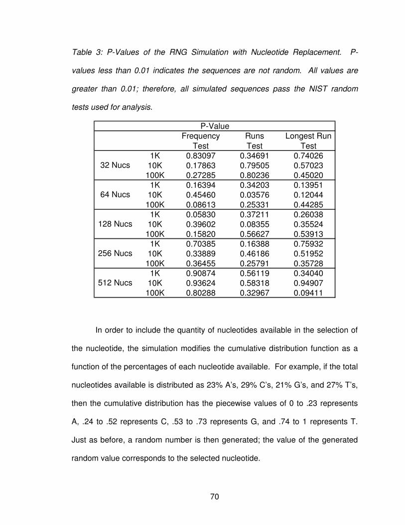
70
Table 3: P-Values of the RNG Simulation with Nucleotide Replacement. P-
values less than 0.01 indicates the sequences are not random. All values are
greater than 0.01; therefore, all simulated sequences pass the NIST random
tests used for analysis.
Frequency
Test
Runs
Test
Longest Run
Test
1K 0.83097 0.34691 0.74026
10K 0.17863 0.79505 0.57023
100K 0.27285 0.80236 0.45020
1K 0.16394 0.34203 0.13951
10K 0.45460 0.03576 0.12044
100K 0.08613 0.25331 0.44285
1K 0.05830 0.37211 0.26038
10K 0.39602 0.08355 0.35524
100K 0.15820 0.56627 0.53913
1K 0.70385 0.16388 0.75932
10K 0.33889 0.46186 0.51952
100K 0.36455 0.25791 0.35728
1K 0.90874 0.56119 0.34040
10K 0.93624 0.58318 0.94907
100K 0.80288 0.32967 0.09411
P-Value
256 Nucs
512 Nucs
32 Nucs
64 Nucs
128 Nucs
In order to include the quantity of nucleotides available in the selection of
the nucleotide, the simulation modifies the cumulative distribution function as a
function of the percentages of each nucleotide available. For example, if the total
nucleotides available is distributed as 23% A’s, 29% C’s, 21% G’s, and 27% T’s,
then the cumulative distribution has the piecewise values of 0 to .23 represents
A, .24 to .52 represents C, .53 to .73 represents G, and .74 to 1 represents T.
Just as before, a random number is then generated; the value of the generated
random value corresponds to the selected nucleotide.
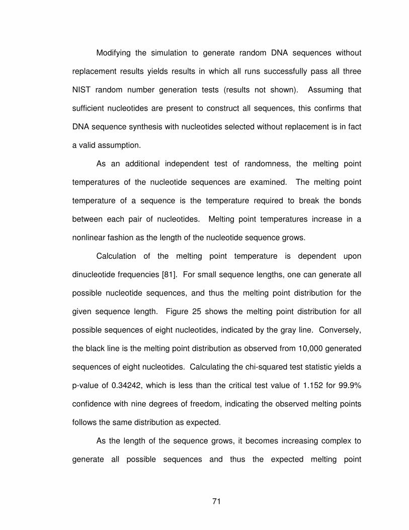
71
Modifying the simulation to generate random DNA sequences without
replacement results yields results in which all runs successfully pass all three
NIST random number generation tests (results not shown). Assuming that
sufficient nucleotides are present to construct all sequences, this confirms that
DNA sequence synthesis with nucleotides selected without replacement is in fact
a valid assumption.
As an additional independent test of randomness, the melting point
temperatures of the nucleotide sequences are examined. The melting point
temperature of a sequence is the temperature required to break the bonds
between each pair of nucleotides. Melting point temperatures increase in a
nonlinear fashion as the length of the nucleotide sequence grows.
Calculation of the melting point temperature is dependent upon
dinucleotide frequencies [81]. For small sequence lengths, one can generate all
possible nucleotide sequences, and thus the melting point distribution for the
given sequence length. Figure 25 shows the melting point distribution for all
possible sequences of eight nucleotides, indicated by the gray line. Conversely,
the black line is the melting point distribution as observed from 10,000 generated
sequences of eight nucleotides. Calculating the chi-squared test statistic yields a
p-value of 0.34242, which is less than the critical test value of 1.152 for 99.9%
confidence with nine degrees of freedom, indicating the observed melting points
follows the same distribution as expected.
As the length of the sequence grows, it becomes increasing complex to
generate all possible sequences and thus the expected melting point
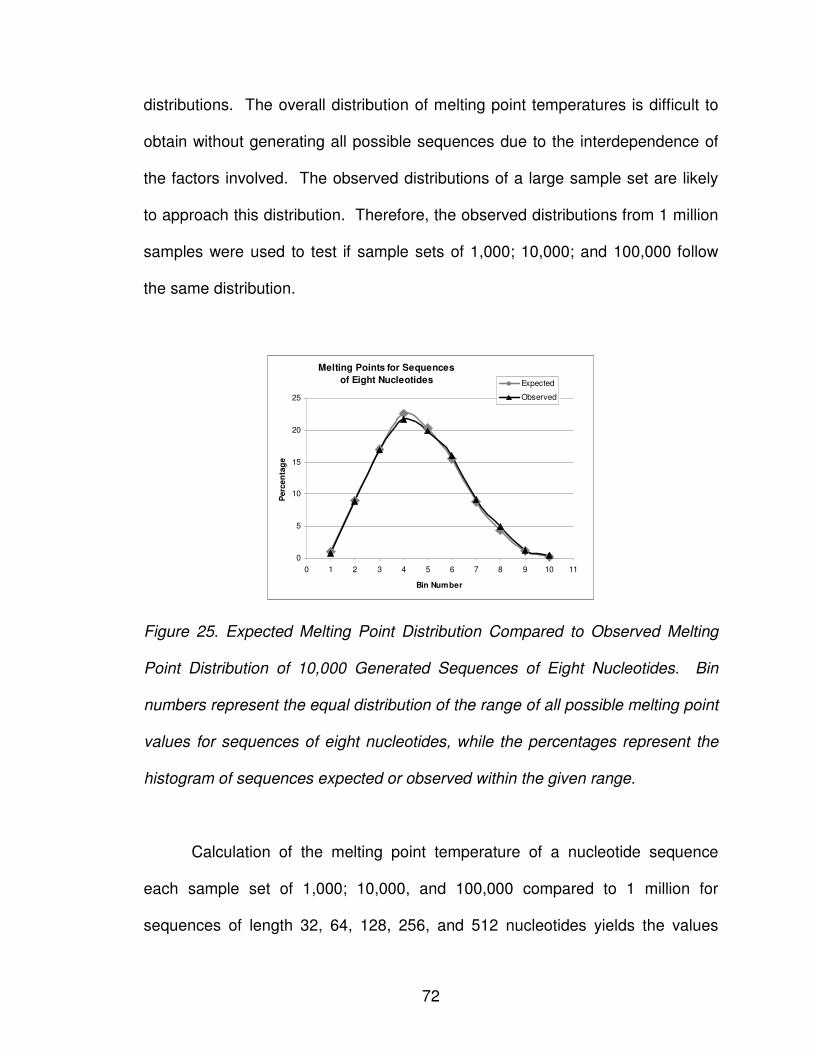
72
distributions. The overall distribution of melting point temperatures is difficult to
obtain without generating all possible sequences due to the interdependence of
the factors involved. The observed distributions of a large sample set are likely
to approach this distribution. Therefore, the observed distributions from 1 million
samples were used to test if sample sets of 1,000; 10,000; and 100,000 follow
the same distribution.
Melting Points for Sequences
of Eight Nucleotides
0
5
10
15
20
25
0 1 2 3 4 5 6 7 8 9 10 11
Bin Number
Perc
en
tag
e
Expected
Observed
Figure 25. Expected Melting Point Distribution Compared to Observed Melting
Point Distribution of 10,000 Generated Sequences of Eight Nucleotides. Bin
numbers represent the equal distribution of the range of all possible melting point
values for sequences of eight nucleotides, while the percentages represent the
histogram of sequences expected or observed within the given range.
Calculation of the melting point temperature of a nucleotide sequence
each sample set of 1,000; 10,000, and 100,000 compared to 1 million for
sequences of length 32, 64, 128, 256, and 512 nucleotides yields the values
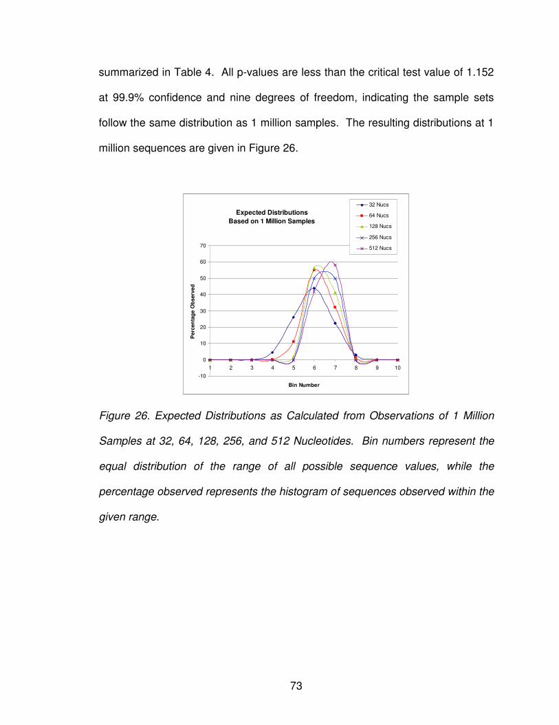
73
summarized in Table 4. All p-values are less than the critical test value of 1.152
at 99.9% confidence and nine degrees of freedom, indicating the sample sets
follow the same distribution as 1 million samples. The resulting distributions at 1
million sequences are given in Figure 26.
Expected Distributions
Based on 1 Million Samples
-10
0
10
20
30
40
50
60
70
1 2 3 4 5 6 7 8 9 10
Bin Number
Perc
en
tag
e O
bserv
ed
32 Nucs
64 Nucs
128 Nucs
256 Nucs
512 Nucs
Figure 26. Expected Distributions as Calculated from Observations of 1 Million
Samples at 32, 64, 128, 256, and 512 Nucleotides. Bin numbers represent the
equal distribution of the range of all possible sequence values, while the
percentage observed represents the histogram of sequences observed within the
given range.
74
Table 4. P-Values of Sample Sets When Compared with 1 Million Samples. All
p-values are less than the critical test value, indicating the sample sets follow the
same distribution as 1 million samples.
1K 10K 100K
32 Nucs 0.76069 0.07354 0.00672
64 Nucs 0.19900 0.01897 0.00585
128 Nucs 0.27373 0.04409 0.00496
256 Nucs 0.22612 0.01580 0.00177
P-Values
Critical Test Value = 1.152, (P=0.001)
9. JUSTIFICATION FOR DNA-BASED RANDOM NUMBER GENERATION
DNA-based random variate generation using solid phase synthesis
enables the development of a myriad of variates in parallel fashion. One cycle of
the proposed random number generator circuitry produces approximately one
million uniformly distributed random variates. However, because of the time
constraints required to chemically create and read the oligonucleotide sequences
within the lab, it is currently faster to digitally generate random variates on a
standard Pentium 4 2GHz computer than generate their DNA-based
counterparts.
However, as research continues, scientists are finding more efficient and
accurate methodologies by which to synthesize oligonucleotides and
systematically read their nucleotide arrays. Thus, it is imaginable the scientists
will one day find a methodology by which DNA-based random variates can be
generated in the same time constraints as their digital equivalents, but not in the
immediately foreseeable future.
75
In addition to the extended time required to generate and read DNA-based
random variates over their digital counterparts, an external transformation is
required to produce variates following non-uniform statistical distributions. Since
there is no current methodology by which to transform variates in parallel, both
digital and DNA-based variates have equivalent conversion times.
Once DNA computing achieves the ability by which to computationally
solve complex mathematical equations, DNA-based uniform variates will be
capable of being simultaneously translated as opposed to the serial
transformation of digital variates. DNA-based random variate generation could
then theoretically rival its digital counterparts in speed if the parallel
transformation processing negates the additional time requirements to chemically
synthesize the oligonucleotide sequences.
76
CHAPTER VI
DESIGN OF A DNA-BASED SHIFT REGISTER
Traditional silicon-based circuitry is susceptible to security attack as a
consequence of the static nature of its design. Metrics utilized to evaluate
security are often based on the 'good feeling' of engineers rather than empirical
evidence. Assessments often result in statements such as "it is practically
impossible to access the memory from the outside" or "it is impossible to access
the data bus that carries the key from storage to the processor if they are all on
the same piece of silicon," diminishing the entire subject of security to a mere art
form rather than scientific proof. The reality is, once a static circuit is obtained by
an attacker, it is a matter of time before one can reverse engineer its
configuration.
True tamper-proof security must satisfy three principle requirements:
resisting static attacks, involving direct penetration of memory cells; and resisting
dynamic attacks, attempting to access information as it is passed from memory
to the processing unit and attempting to access information during actual
processing [82]. To circumvent such tampering, circuits must be dynamic by
nature. We argue that DNA-based logic circuits, when the technology matures,
may provide revolutionary solutions to tamper proofing. A DNA-based design
77
enables circuitry to be based on biochemical and environmental stimuli. Discrete
components, such as those observed in CMOS circuits, are non-existent.
Tampering would thus have new meaning, possibly preventing it altogether
based on accurate scientific observations.
With this vision in mind, biological methodologies have been developed to
mimic existing silicon-based technologies in data manipulation as a first step.
Within the digital world, data manipulation encompasses a number of essential
processes, including data generation, storage, retrieval, and processing. In
terms of complexity, data storage and retrieval is considered the least difficult.
As such, the first research element is to introduce a methodology by which
information could reliably be stored and retrieved within a DNA sequence (see
Chapter IV: DNA Media Storage).
The next research component is to devise a methodology by which one
could generate information. A novel schema for a microfluidic chip was
developed; solid phase synthesis enables random sequence generation, plasmid
vectors in conjunction with restriction enzymes enable temporary storage, and
chromatograms enable the random value to be output to the user (see Chapter
V: Random Number Generation Circuitry).
Once a methodology is in place to generate and store information in a
DNA-based computer, the final step is to connect this information together to
create a logic-based system. A shift register is a primary component of the
computational processor that enables information computation at a gate level
followed by shifting of the information to the proceeding gate. Simply moving the
78
data by itself has no computational meaning. A shift register requires the
integration of both logic and shifting, thereby creating a complete processing unit
that performs serial calculations on an input stream of information. Thus, its
development is critical to the continued advancement of DNA computing.
1. DNA-BASED LOGIC GATES
DNA has a number of characteristics that enable one to mimic traditional
logical operations, as discussed in Chapters III: Designing Biological Logic
Gates. DNA prefers to be in double stranded form, while single stranded DNA
sequences naturally migrate towards complementary sequences to form double
stranded complexes. Complementary sequences pair the bases adenine (A)
with thymine (T) and cytosine (C) with guanine (G). DNA sequences pair in an
antiparallel manner, with the 5’ end of one sequence pairing with the
corresponding 3’ end of the complementary sequence. When complementary
sequences are written in the 5’ � 3’ direction, the complementary sequence
pairing is observed in the opposite order (read right to left), and is called the
reverse complement [73]. Consider the complementary sequences
ACTGACGGA and TCCGTCAGT. The complementary base of the first A of the
first sequence is the last T of the second sequence. Likewise, the second base,
C, of the first sequence pairs with the second to last base, G, of the second
sequence.
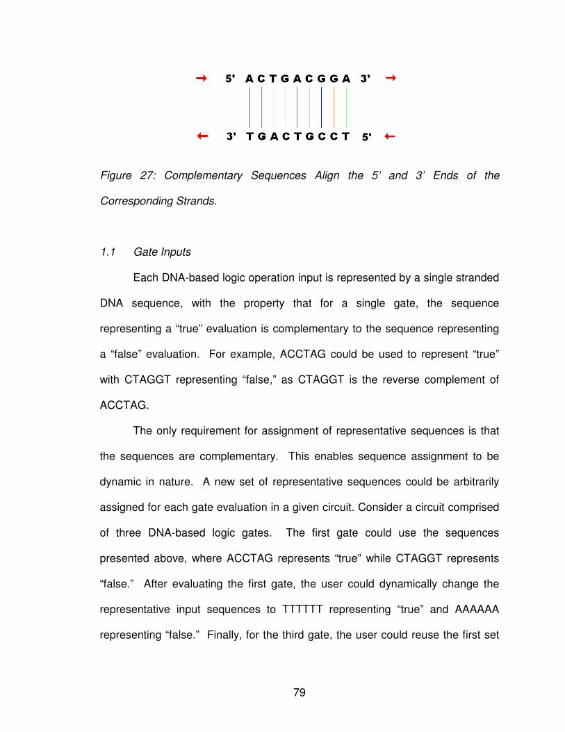
79
Figure 27: Complementary Sequences Align the 5’ and 3’ Ends of the
Corresponding Strands.
1.1 Gate Inputs
Each DNA-based logic operation input is represented by a single stranded
DNA sequence, with the property that for a single gate, the sequence
representing a “true” evaluation is complementary to the sequence representing
a “false” evaluation. For example, ACCTAG could be used to represent “true”
with CTAGGT representing “false,” as CTAGGT is the reverse complement of
ACCTAG.
The only requirement for assignment of representative sequences is that
the sequences are complementary. This enables sequence assignment to be
dynamic in nature. A new set of representative sequences could be arbitrarily
assigned for each gate evaluation in a given circuit. Consider a circuit comprised
of three DNA-based logic gates. The first gate could use the sequences
presented above, where ACCTAG represents “true” while CTAGGT represents
“false.” After evaluating the first gate, the user could dynamically change the
representative input sequences to TTTTTT representing “true” and AAAAAA
representing “false.” Finally, for the third gate, the user could reuse the first set
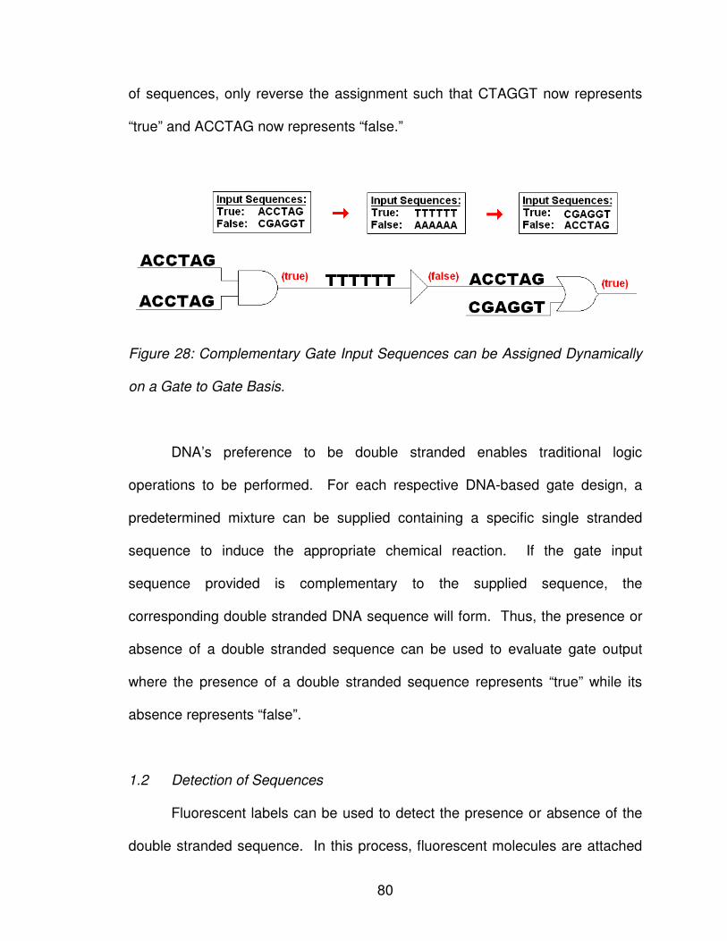
80
of sequences, only reverse the assignment such that CTAGGT now represents
“true” and ACCTAG now represents “false.”
Figure 28: Complementary Gate Input Sequences can be Assigned Dynamically
on a Gate to Gate Basis.
DNA’s preference to be double stranded enables traditional logic
operations to be performed. For each respective DNA-based gate design, a
predetermined mixture can be supplied containing a specific single stranded
sequence to induce the appropriate chemical reaction. If the gate input
sequence provided is complementary to the supplied sequence, the
corresponding double stranded DNA sequence will form. Thus, the presence or
absence of a double stranded sequence can be used to evaluate gate output
where the presence of a double stranded sequence represents “true” while its
absence represents “false”.
1.2 Detection of Sequences
Fluorescent labels can be used to detect the presence or absence of the
double stranded sequence. In this process, fluorescent molecules are attached
81
to the nucleotide sequence, and absorb and emit light at a particular wavelength.
Thus, by attaching the fluorescent molecule to one of the strands of the double
stranded sequence, the double stranded sequence can be detected as present
by examining the sequence solution at the fluorescent probe’s characteristic
wavelength.
One efficient methodology for fluorescently labeling a nucleotide sequence
is direct bonding of the fluorescent dye to the sequence chain through the sugar
ring, the phosphate backbone, or directly to the nucleotide itself [11]. To label
the sugar ring, DNA depurination frees the aldehde group of the terminating
sugar (5’ or 3’ end) such that it can form a covalent bond with the fluorescent
agent. Conversely, labeling the phosphate backbone is achieved by synthesizing
a dansyl derivative that directly reacts with the 5’-phosphate end of the
nucleotide chain.
Directly labeling the nucleotide base involves reacting with one or more of
the positional bases of the nucleotides. Since the single stranded sequence will
be utilized in annealing to the complementary strand, it is critical that the
fluorescent dye reaction does not interfere with sites involved in base pairing.
Pyrimidine (thymine and adenine) labeling can be achieved through a cyclo-
addition reaction at the 5th- and 6th- positions, while purine (cytosine and
guanine) labeling can be achieved through an acetamide reaction at the 8th-
position [11]. It is worth noting that not every nucleotide needs to be
fluorescently labeled. A representative nucleotide (such as guanine) could be
labeled within the sequence to observe the presence of the sequence.
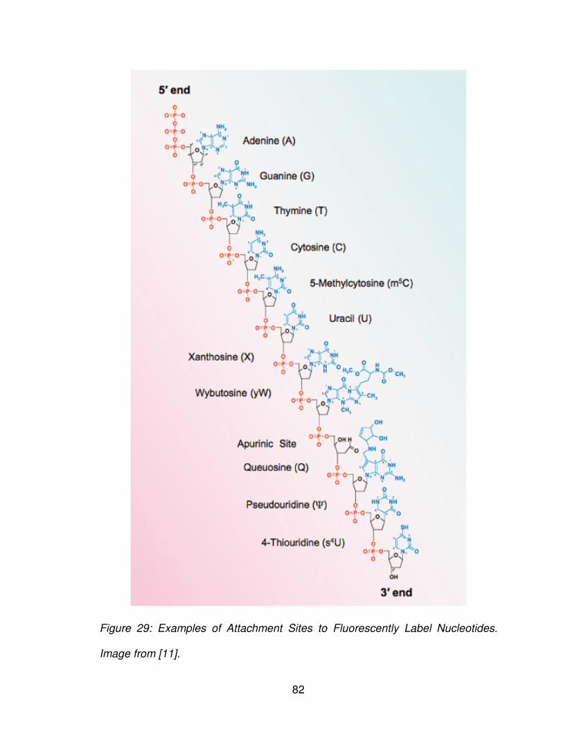
82
Figure 29: Examples of Attachment Sites to Fluorescently Label Nucleotides.
Image from [11].
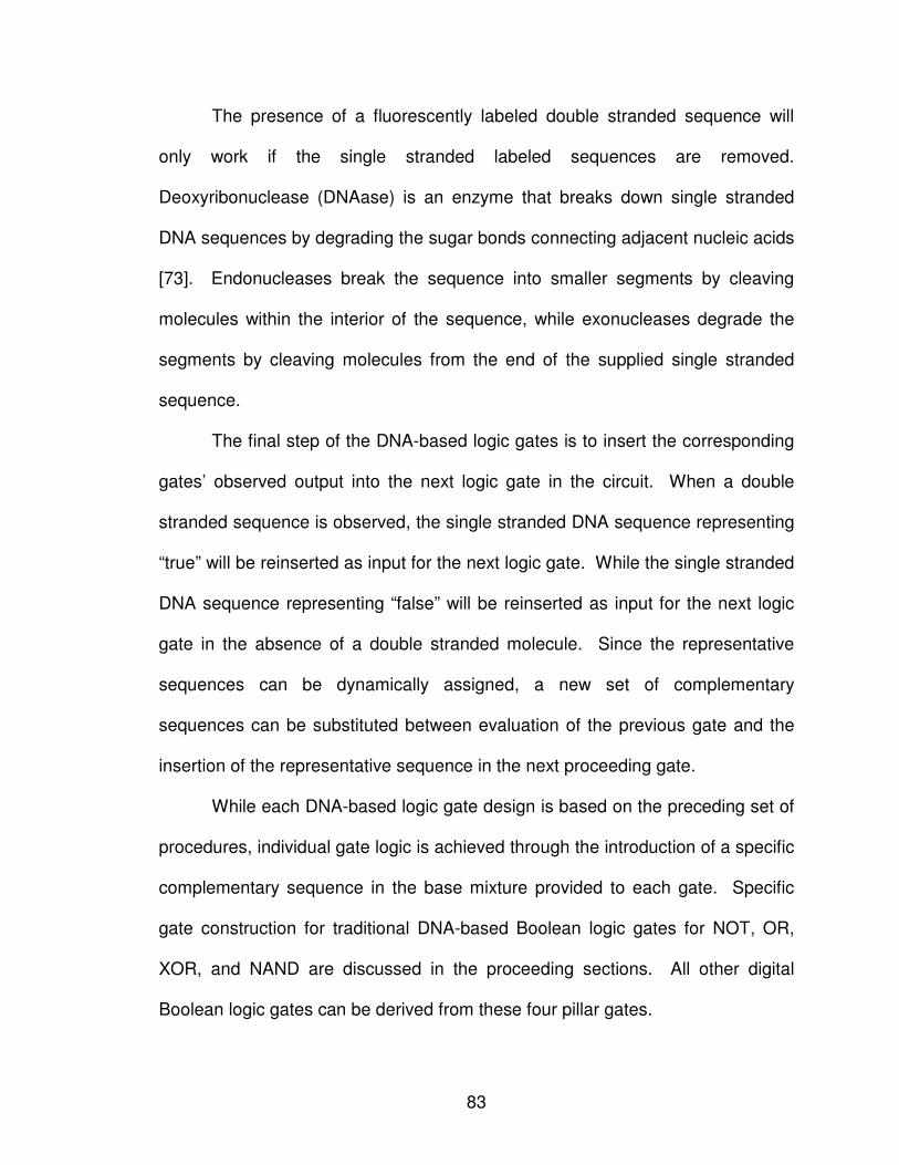
83
The presence of a fluorescently labeled double stranded sequence will
only work if the single stranded labeled sequences are removed.
Deoxyribonuclease (DNAase) is an enzyme that breaks down single stranded
DNA sequences by degrading the sugar bonds connecting adjacent nucleic acids
[73]. Endonucleases break the sequence into smaller segments by cleaving
molecules within the interior of the sequence, while exonucleases degrade the
segments by cleaving molecules from the end of the supplied single stranded
sequence.
The final step of the DNA-based logic gates is to insert the corresponding
gates’ observed output into the next logic gate in the circuit. When a double
stranded sequence is observed, the single stranded DNA sequence representing
“true” will be reinserted as input for the next logic gate. While the single stranded
DNA sequence representing “false” will be reinserted as input for the next logic
gate in the absence of a double stranded molecule. Since the representative
sequences can be dynamically assigned, a new set of complementary
sequences can be substituted between evaluation of the previous gate and the
insertion of the representative sequence in the next proceeding gate.
While each DNA-based logic gate design is based on the preceding set of
procedures, individual gate logic is achieved through the introduction of a specific
complementary sequence in the base mixture provided to each gate. Specific
gate construction for traditional DNA-based Boolean logic gates for NOT, OR,
XOR, and NAND are discussed in the proceeding sections. All other digital
Boolean logic gates can be derived from these four pillar gates.
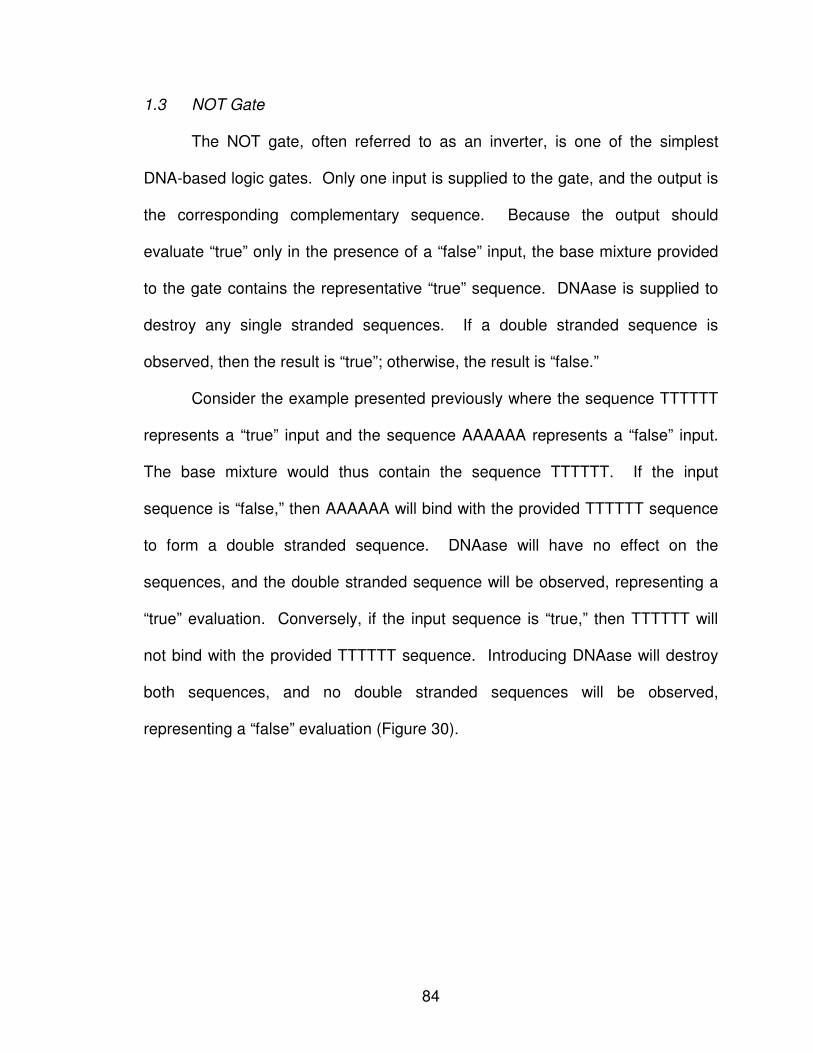
84
1.3 NOT Gate
The NOT gate, often referred to as an inverter, is one of the simplest
DNA-based logic gates. Only one input is supplied to the gate, and the output is
the corresponding complementary sequence. Because the output should
evaluate “true” only in the presence of a “false” input, the base mixture provided
to the gate contains the representative “true” sequence. DNAase is supplied to
destroy any single stranded sequences. If a double stranded sequence is
observed, then the result is “true”; otherwise, the result is “false.”
Consider the example presented previously where the sequence TTTTTT
represents a “true” input and the sequence AAAAAA represents a “false” input.
The base mixture would thus contain the sequence TTTTTT. If the input
sequence is “false,” then AAAAAA will bind with the provided TTTTTT sequence
to form a double stranded sequence. DNAase will have no effect on the
sequences, and the double stranded sequence will be observed, representing a
“true” evaluation. Conversely, if the input sequence is “true,” then TTTTTT will
not bind with the provided TTTTTT sequence. Introducing DNAase will destroy
both sequences, and no double stranded sequences will be observed,
representing a “false” evaluation (Figure 30).
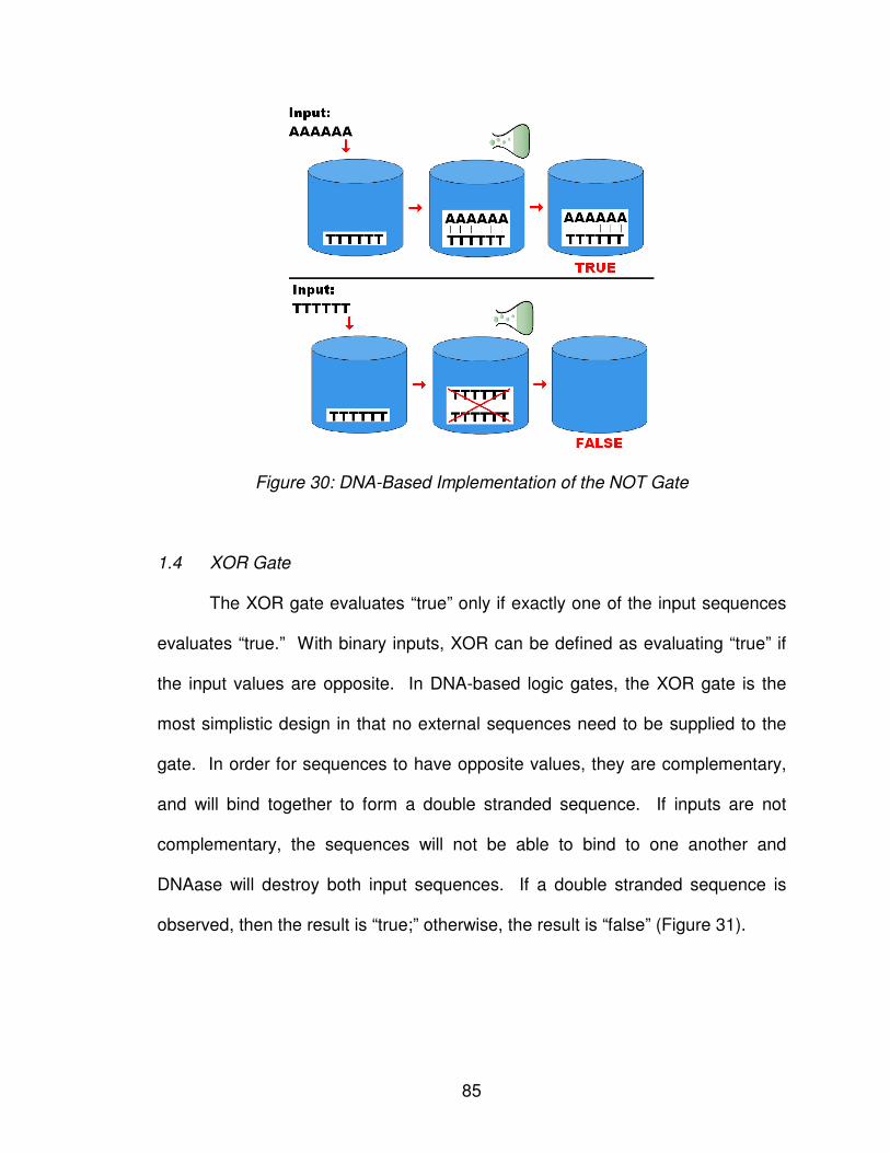
85
Figure 30: DNA-Based Implementation of the NOT Gate
1.4 XOR Gate
The XOR gate evaluates “true” only if exactly one of the input sequences
evaluates “true.” With binary inputs, XOR can be defined as evaluating “true” if
the input values are opposite. In DNA-based logic gates, the XOR gate is the
most simplistic design in that no external sequences need to be supplied to the
gate. In order for sequences to have opposite values, they are complementary,
and will bind together to form a double stranded sequence. If inputs are not
complementary, the sequences will not be able to bind to one another and
DNAase will destroy both input sequences. If a double stranded sequence is
observed, then the result is “true;” otherwise, the result is “false” (Figure 31).
86
Figure 31: DNA-Based Implementation of the XOR Gate
1.5 OR Gate
The OR gate evaluates “true” if one or both of the gate inputs are “true.”
Introducing the “false” sequence in the base mixture will require at least one of
the inputs be “true” in order to form a double stranded sequence. DNAase will
destroy any single stranded sequence in the mixture. If a double stranded
sequence is observed, then the result is “true”; otherwise, the result is “false.”
Consider the example above where the sequence TTTTTT represents a
“true” input and the sequence AAAAAA represents a “false” input. If both of the
input sequences are “true” TTTTTT sequences, then one of the sequences will
combine with the supplied “false” AAAAAA sequence to produce a double
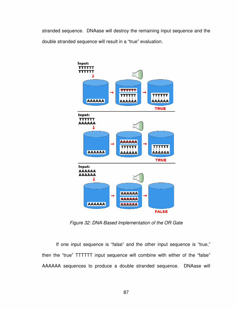
87
stranded sequence. DNAase will destroy the remaining input sequence and the
double stranded sequence will result in a “true” evaluation.
Figure 32: DNA-Based Implementation of the OR Gate
If one input sequence is “false” and the other input sequence is “true,”
then the “true” TTTTTT input sequence will combine with either of the “false”
AAAAAA sequences to produce a double stranded sequence. DNAase will
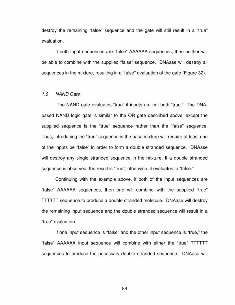
88
destroy the remaining “false” sequence and the gate will still result in a “true”
evaluation.
If both input sequences are “false” AAAAAA sequences, then neither will
be able to combine with the supplied “false” sequence. DNAase will destroy all
sequences in the mixture, resulting in a “false” evaluation of the gate (Figure 32).
1.6 NAND Gate
The NAND gate evaluates “true” if inputs are not both “true.” The DNA-
based NAND logic gate is similar to the OR gate described above, except the
supplied sequence is the “true” sequence rather than the “false” sequence.
Thus, introducing the “true” sequence in the base mixture will require at least one
of the inputs be “false” in order to form a double stranded sequence. DNAase
will destroy any single stranded sequence in the mixture. If a double stranded
sequence is observed, the result is “true”; otherwise, it evaluates to “false.”
Continuing with the example above, if both of the input sequences are
“false” AAAAAA sequences, then one will combine with the supplied “true”
TTTTTT sequence to produce a double stranded molecule. DNAase will destroy
the remaining input sequence and the double stranded sequence will result in a
“true” evaluation.
If one input sequence is “false” and the other input sequence is “true,” the
“false” AAAAAA input sequence will combine with either the “true” TTTTTT
sequences to produce the necessary double stranded sequence. DNAase will
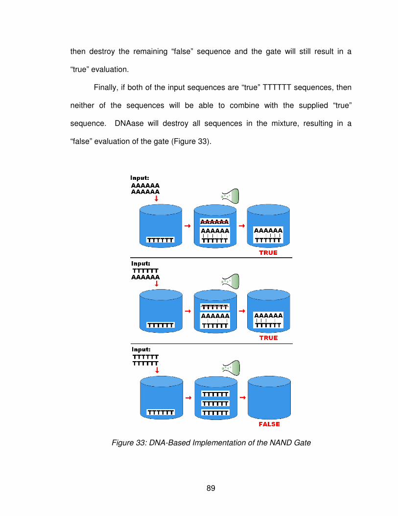
89
then destroy the remaining “false” sequence and the gate will still result in a
“true” evaluation.
Finally, if both of the input sequences are “true” TTTTTT sequences, then
neither of the sequences will be able to combine with the supplied “true”
sequence. DNAase will destroy all sequences in the mixture, resulting in a
“false” evaluation of the gate (Figure 33).
Figure 33: DNA-Based Implementation of the NAND Gate
90
1.7 AND, NOR, and XNOR Gates
NOT, XOR, OR, and NAND represent four of the seven most common
Boolean logic gates. From these four DNA-based logic gates, one can devise a
DNA-based representation for all other digital Boolean logic gates. Consider the
three remaining digital logic gates of the seven most common – AND, NOR, and
XNOR. The AND gate, which evaluates “true” only when both inputs are “true,”
is created by applying the NOT gate to the output of the NAND gate. The NOR
gate, which evaluates “true” when both inputs are “false,” is created by applying
the NOT gate to the result of the OR gate. Finally, the XNOR gate, which
evaluates “true” when both inputs are the same, is created by applying the NOT
gate to one of the inputs, then applying the XOR gate to the result and the other
input. Like the preceding gate designs, the presence of a double stranded
sequence indicates a “true” evaluation of the gate, while the absence of a double
stranded sequence indicates a “false” evaluation of the gate.
1.8 Obfuscating the Logic Gates
It is worth noting the significant contribution of the DNA-based gate design
described. Gates are obfuscated by removing the physical sequence
connections present in current DNA-based designs. Current logic gate designs
enable circuits to be reverse engineered by examining the unique alignment
sequences used to represent specific logic gates. The proposed gates are a
function of the chemical reactions among input sequences and base mixtures,
meaning the physical blueprint of the circuit cannot simply be observed.
91
One can further obfuscate the shift register design by altering the input
sequence representative strands. “True” and “false” sequences can be any
complementary pair of DNA sequences, where adenine (A) is complementary of
thymine (T) and cytosine (C) is complementary of guanine (G). For simplicity,
the examples above use the sequence AAAAAA to represent “false” and the
sequence TTTTTT to represent “true.” However, the sequence ACCTAG could
just as easily been used to represent “true” and the sequence CGAGGT as
“false.”
This obfuscation is further enhanced by enabling a variety of sequence
combinations representing “true” and “false” to be utilized throughout the circuit
evaluation. Because the design is a chemical reaction among sequences, and
the single stranded sequence corresponding to the preceding gate’s output is
supplied to the proceeding gate, one could systematically change the
representative sequences at any transitional points between gates. This
introduces an interesting phenomenon in the evaluation of the circuit. Even if an
outsider is able to determine the output sequence, one would not be able to
decipher if the sequence represents a “true” or “false” evaluation.
Furthermore, the length of the sequences could be easily modified. Six
was chosen to achieve a low probability of 1:46 (1:4096) that the sequence would
randomly align. It is equally attainable to create input sequences of 100
nucleotides or greater in length, yielding a probability of 1:4n, where n is the
length of the sequence.
92
1.9 From Logic Gates to Circuits
With each DNA-based logic gate having a variety of sequence
combinations representing “true” and “false,” a feedback mechanism must be
implemented by which a gate can interpret the output of the preceding gate.
Without introducing a feedback mechanism, input sequences may have no valid
meaning. If two gates, each with a unique set of input sequences, serve as
inputs into a third gate, there must be a method by which the gate output can be
accurately relayed as a valid input into the new gate. Without such
communication, the proceeding gate will not be able to form the double stranded
molecule, always resulting in a “false” output evaluation.
One method by which gates with distinctive inputs could communicate is
through a “look ahead” mechanism, wherein the current gate could format its
output in terms of the proceeding gate. The proposed molecular logic gate
design evaluation of output is based on the presence or absence of the double
stranded sequence; the single stranded input sequence for the next sequential
gate is then constructed using DNA replication. Rather than constructing the
single stranded sequence representing the output based on current gate’s
associated sequences, the single stranded sequence can be constructed from
the proceeding gate’s sequence pair.
Consider the circuit presented in Figure 34, wherein the outputs from an
AND gate and an OR gate are combined through a XOR gate. Input for the AND
gate is the sequence combination ACCTAG and CTAGGT, while input for the OR
gate is the sequence combination TTGCAT and ATGCAA each representing
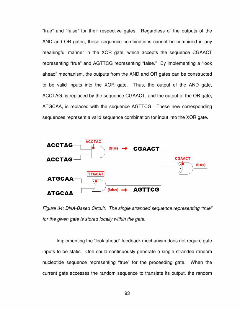
93
“true” and “false” for their respective gates. Regardless of the outputs of the
AND and OR gates, these sequence combinations cannot be combined in any
meaningful manner in the XOR gate, which accepts the sequence CGAACT
representing “true” and AGTTCG representing “false.” By implementing a “look
ahead” mechanism, the outputs from the AND and OR gates can be constructed
to be valid inputs into the XOR gate. Thus, the output of the AND gate,
ACCTAG, is replaced by the sequence CGAACT, and the output of the OR gate,
ATGCAA, is replaced with the sequence AGTTCG. These new corresponding
sequences represent a valid sequence combination for input into the XOR gate.
Figure 34: DNA-Based Circuit. The single stranded sequence representing “true”
for the given gate is stored locally within the gate.
Implementing the “look ahead” feedback mechanism does not require gate
inputs to be static. One could continuously generate a single stranded random
nucleotide sequence representing “true” for the proceeding gate. When the
current gate accesses the random sequence to translate its output, the random
94
sequence is locked from further changes. Locking the random sequence
ensures all inputs to the gate are valid sequences because all are generated
from the same random sequence. Once all inputs to the gate have been
generated, the lock is removed and random sequences are continually generated
for the given gate. A feedback mechanism implemented in this manner
maintains the dynamic nature of gate inputs without continued interaction from
the circuit designer.
1.10 Non-Boolean DNA-Based Logic Gates
A DNA-based design to logic gates enables one to break out of the
Boolean logic mentality. By design, digital circuits are limited to the Boolean
inputs of zero and one. DNA, however, is comprised of four nucleotides –
adenine (A), cytosine (C), guanine (G), and thymine (T), enabling four possible
input values, not two. With four inputs, output values are no longer restricted
exclusively to “true” or “false.” Rather, one can now consider three possible
output values for a DNA-based logic gate design – (1) inputs are identical, (2)
inputs are complementary, or (3) inputs are different. An output of “identical”
implies the two nucleotide inputs are the same nucleotide base. An output of
“complementary” implies the first input base will pair when in the presence of the
second. Complementary input sequences pair adenine (A) and thymine (T)
bases and pair cytosine (C) and guanine (G) bases. Finally, an output of
“different” implies the two nucleotide input bases are neither the same nor
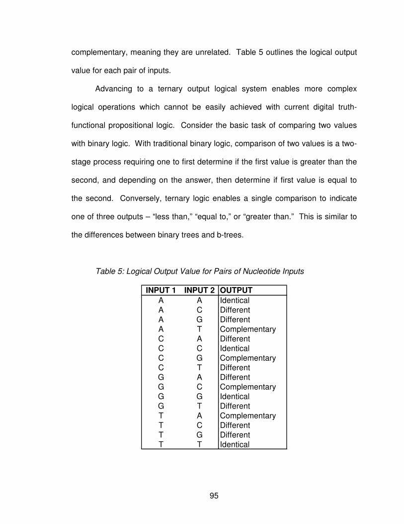
95
complementary, meaning they are unrelated. Table 5 outlines the logical output
value for each pair of inputs.
Advancing to a ternary output logical system enables more complex
logical operations which cannot be easily achieved with current digital truth-
functional propositional logic. Consider the basic task of comparing two values
with binary logic. With traditional binary logic, comparison of two values is a two-
stage process requiring one to first determine if the first value is greater than the
second, and depending on the answer, then determine if first value is equal to
the second. Conversely, ternary logic enables a single comparison to indicate
one of three outputs – “less than,” “equal to,” or “greater than.” This is similar to
the differences between binary trees and b-trees.
Table 5: Logical Output Value for Pairs of Nucleotide Inputs
INPUT 1 INPUT 2 OUTPUT
A A Identical
A C Different
A G Different
A T Complementary
C A Different
C C Identical
C G Complementary
C T Different
G A Different
G C Complementary
G G Identical
G T Different
T A Complementary
T C Different
T G Different
T T Identical
96
With ternary systems having the benefit of an additional output stage over
their binary counterparts, why did ternary systems fail to thrive? The twentieth
century has multiple attempts to design and fabricate digital tri-state logic gates,
including the Setun system developed at Moscow State University [83] and the
ternac system developed at the State University of New York at Buffalo [84].
While some were successful, solutions were often cost-prohibitive and unreliable
when compared to their binary counterparts. DNA-based logic gates are the first
proposed solution to naturally produce a ternary logical system.
The benefits of DNA-based logic gates are not limited to the reduction in
the number of the gates based on the additional representation of an additional
output state; it also enables circuits to be compressed based on inputs. The
proposed DNA-based logic gate output evaluation is based solely on the
presence or absence of the double stranded molecule. Thus, a myriad of input
sequences can be condensed into a single gate mixture. For example, a series
of OR gates can be integrated into a single DNA-based OR gate. The presence
of a single “true” sequence in the mixture will result in the formation of the double
stranded molecule regardless of the magnitude of inputs present. Perhaps the
benefits of DNA-based logic gate design lies not in mimicking the Boolean logic
of their digital counterparts, but in devising a new set of logical operations
enabled by the ternary logic structure combined with the DNA-based design.
97
2. THE SHIFTING ELEMENT
A shift register is a primary component of the computational processor that
enables information computation at a gate level and then shifts the information to
the proceeding gate [53]. Simply moving the data by itself has no computational
meaning. A shift register requires the integration of both logic and shifting,
thereby creating a complete processing unit that performs serial calculations on
an input stream of information. It is the integration of logic and shifting that
enables information processing and computation in a shift register. Therefore,
the ability to integrate will be the defining characteristic in determining which
biological elements will be incorporated into the shift register.
2.1 Biological Approach to Shifting
The biological process of alternative splicing naturally lends itself to
isolating a given segment of information from the stream of data for a DNA-based
shift register. Alternative splicing is a molecular biology process utilized to
produce multiple protein isoforms from a single gene through various
sequentially-ordered subset permutations of the set of possible exons [73]. A
DNA sequence is subdivided into exons, encoding regions of nucleic acid
sequences expressed in translation for protein formation, and introns, non-coding
regions of nucleic acid sequences independent of protein formation. Prior to
protein formation, intronic regions are discarded while select exonic regions are
recombined in sequential order. The protein isoform being created determines
which, if any, exonic regions will be discarded. Figure 35 shows three of the

98
possible fifteen splices that can be created from the four exonic DNA: (1)
combining the first, third, and last exons, (2) combining all four exonic regions,
(3) combining the first, second, and last exons. The splicing of different exons to
produce distinct proteins is called alternative splicing.
It is important to note that any subset of exons is a valid splice
permutation only if sequential order is maintained. Permutations not maintaining
sequential ordering are not valid splices for protein isoforms. For example, the
alternative splice combining the second, first, and last exons is invalid because
the second exon precedes the first exon.
Figure 35: Alternative Splicing Enables Specific Exonic Regions of DNA to be
Selected from the Entire Sequence. Intronic regions, indicated in white, are
spliced from the sequence. The remaining exonic regions are sequentially
concatenated to form valid alternative splices.
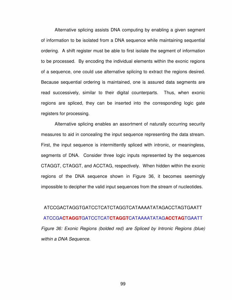
99
Alternative splicing assists DNA computing by enabling a given segment
of information to be isolated from a DNA sequence while maintaining sequential
ordering. A shift register must be able to first isolate the segment of information
to be processed. By encoding the individual elements within the exonic regions
of a sequence, one could use alternative splicing to extract the regions desired.
Because sequential ordering is maintained, one is assured data segments are
read successively, similar to their digital counterparts. Thus, when exonic
regions are spliced, they can be inserted into the corresponding logic gate
registers for processing.
Alternative splicing enables an assortment of naturally occurring security
measures to aid in concealing the input sequence representing the data stream.
First, the input sequence is intermittently spliced with intronic, or meaningless,
segments of DNA. Consider three logic inputs represented by the sequences
CTAGGT, CTAGGT, and ACCTAG, respectively. When hidden within the exonic
regions of the DNA sequence shown in Figure 36, it becomes seemingly
impossible to decipher the valid input sequences from the stream of nucleotides.
ATCCGACTAGGTGATCCTCATCTAGGTCATAAAATATAGACCTAGTGAATT
ATCCGACTAGGTGATCCTCATCTAGGTCATAAAATATAGACCTAGTGAATT
Figure 36: Exonic Regions (bolded red) are Spliced by Intronic Regions (blue)
within a DNA Sequence.
100
In addition to concealing input sequences within a stream of nucleotides,
alternative splicing enables one to selectively choose which inputs to apply to a
given gate. For example, if the input stream in Figure 36 represents the two
input values for a DNA-based AND gate, one has three valid pairs of inputs from
which to choose: (1) the first and second exons, (2) the first and third exons, and
(3) the second and third exons. Even if an intruder were to determine which
regions were exonic, and thus which sequences represent the logic gate inputs,
he or she would be left with only a probabilistic guess as to which exonic regions
would be selected.
2.2 Implementing Alternative Splicing
While alternative splicing occurs naturally and seems ideal in theory to
implement the shifting aspect, it is impractical to synthetically coerce splicing to
occur at designated locations. To date, the mechanisms by which DNA selects
exonic regions from a given sequence are not fully understood. Inserting foreign
DNA sequences into exonic regions could yield unpredictable results. There is
no guarantee the intended input sequence will not be spliced out as an intronic
region from the input stream.
However, one can mimic the functionality of alternative splicing through
the use of restriction enzymes. A restriction enzyme is a small protein sequence
that aligns with a specific complementary DNA sequence and cleaves the
sequence at such location (Klug and Cummings 2003). In mimicking alternative
splicing, input sequences are inserted between predetermined restriction enzyme
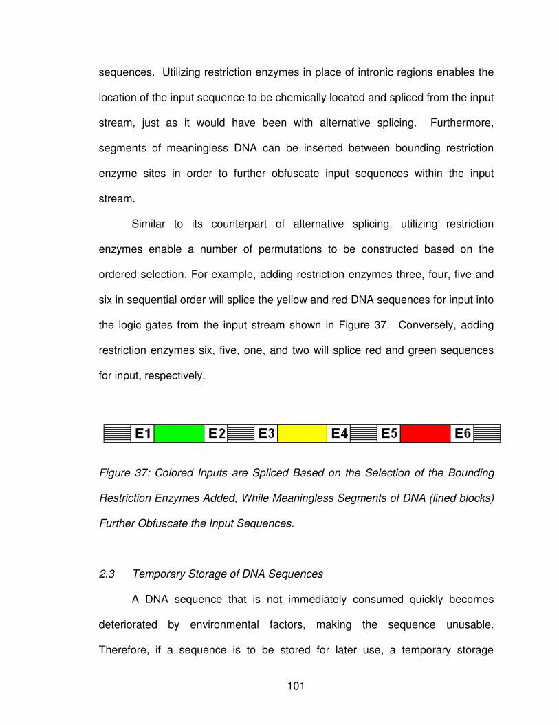
101
sequences. Utilizing restriction enzymes in place of intronic regions enables the
location of the input sequence to be chemically located and spliced from the input
stream, just as it would have been with alternative splicing. Furthermore,
segments of meaningless DNA can be inserted between bounding restriction
enzyme sites in order to further obfuscate input sequences within the input
stream.
Similar to its counterpart of alternative splicing, utilizing restriction
enzymes enable a number of permutations to be constructed based on the
ordered selection. For example, adding restriction enzymes three, four, five and
six in sequential order will splice the yellow and red DNA sequences for input into
the logic gates from the input stream shown in Figure 37. Conversely, adding
restriction enzymes six, five, one, and two will splice red and green sequences
for input, respectively.
Figure 37: Colored Inputs are Spliced Based on the Selection of the Bounding
Restriction Enzymes Added, While Meaningless Segments of DNA (lined blocks)
Further Obfuscate the Input Sequences.
2.3 Temporary Storage of DNA Sequences
A DNA sequence that is not immediately consumed quickly becomes
deteriorated by environmental factors, making the sequence unusable.
Therefore, if a sequence is to be stored for later use, a temporary storage
102
mechanism must be provided to preserve the sequence. One method of
temporary storage involves inserting the sequence into plasmid vectors. This
technique is covered in detail in Section 5.4.
In order to retrieve the random sequence from the vector, the process of
insertion is reversed. Once again the restriction enzyme is aligned with the
vector to cleave the DNA. The next n bases are sequentially read from the
vector, where n represents the length of the random oligonucleotide sequence,
and finally the vector is reconstructed to its original circular molecule. It is
important to note that the retrieval of the enzyme requires three components: (1)
the plasmid vector with inserted sequence, (2) the restriction enzyme used to
initially insert the random sequence, and (3) the length of the random sequence.
3. CIRCUIT FABRICATION
It is imperative to assess the practicality of fabricating the proposed DNA-
based shift register using current and envisioned future technologies. To begin,
elements selected for use in the prototype schema are tools and techniques
currently employed in biochemical and molecular laboratories on a microscopic
level. Requiring such enables one to theoretically be able to construct the circuit
here and now, provided funding and resource availability. While the end goal is
mass production, invention of prototypes demonstrating successful integration
are often cost prohibitive initially.
Fabrication requires the presence of the microfluidic inputs to the circuit,
including the single stranded DNA sequences, fluorescently labeled molecules,
103
DNAase, restriction enzymes and plasmid vectors. Liquids do not dry up; rather,
they are consumed by the circuit just as electricity is consumed by their silicon
counterparts. This is not considered a limitation of DNA-based circuitry.
Regardless of the venue, there is no perpetual circuit in existence. Just as the
silicon chip must be replenished with electricity to remain functional, the DNA
chip must be replenished with nucleotide solutions, plasmid vectors, and
restriction enzymes.
DNA-based circuit design is inherently scalable on an almost endless
spectrum. This is enabled by integrating input sequence construction with the
evaluation of the preceding logic gate. Essentially such a design eliminates fan-
out limitations on circuit size found in digital counterparts. It is envisioned that
single stranded inputs are created dynamically just prior to individual gate
evaluation, reducing degradation of input sequences, while other microfluidic
resources required are continually pulled as needed from an on-board renewable
well.
104
CHAPTER VII
CONCLUSION
Adleman hypothesized that ‘‘for the long-term, one can only speculate
about the prospects for molecular computation.” With each new theory
introduced, we move closer to the practical applications afforded by DNA
computing. It is unrealistic to predict DNA computing will form the sole basis of
the next generation of technology; however, when combined with current
technologies, could form a hybridization capable of achieving the fast
computational benefits of DNA with the flexibility of current silicon.
DNA-based circuit design is continually evolving as DNA paradigms can
be developed to represent their digital equivalents. This research is dedicated to
the development of DNA-based methodologies to mimic the digitally based data
manipulation counterpart. DNA-based circuitry, when the technology matures,
has the potential to form the basis for a tamper-proof security module,
revolutionizing the meaning and concept of tamper-proofing and possibly
preventing it altogether based on accurate scientific observations.
First, a novel approach in which DNA could theoretically be used as a
means of storing files is introduced. Through the use of multiple sequence
alignment combined with intelligent heuristics, the most probabilistic file contents
105
can be determined with minimal errors. Completely conserved regions have no
discrepancies and as such are 100% error free. Highly conserved regions have
minimal discrepancies, whose correct content can be determined based on the
emission probabilities of the associated Hidden Markov Model. Finally, poorly
conserved regions represent the most difficult areas because of the high
discrepancies with low emission probabilities. However, using the associated
translated amino acid sequences, it is possible to improve the accuracy of the
region’s emission probabilities with multiple codons encoding a single amino
acid.
The next research component devised is a random number generation
circuitry, demonstrating how data can be generated using DNA sequences. A
random number generation (RNG) circuitry demonstrates how a microfluidic
device can act as a random number generator. A novel prototype schema
employs solid-phase synthesis of oligonucleotides for random construction of
DNA sequences; temporary storage is achieved through plasmid vectors;
chromatogram analysis enables the translation from a sequence to its digitally
equivalent random number. Long term storage is achieved through spotted
microarray fabrication, which enables each sequence’s expression levels to be
permanently stored. To verify randomness, one must verify that sequences have
uniformity and are non-correlated. A wet-lab experiment is required to verify no
correlation exists between the previously selected nucleotide and the next
randomly selected nucleotide in sequence generation. After generating a
multitude of sequences, they must be translated into their digital form through a
106
chromatogram. A discussion of how to evaluate sequence randomness is
included, as well as how these techniques are applied to a simulation of the
random number generation circuitry. Simulation results show generated
sequences successfully pass three selected NIST random number generation
tests.
Once a methodology is in place to generate and store information in a
DNA-based computer, the final step is to connect this information together to
create a logic-based system. A shift register requires the integration of both logic
and shifting, thereby creating a complete processing unit that performs serial
calculations on an input stream of information. A novel logic gate design based
on chemical reactions is presented in which observance of double stranded
sequences indicates a truth evaluation. Circuits are obfuscated by removing of
physical sequence connections, allowing client-specific representative strands for
input sequences, altering the input sequence strands over time, and varying the
input sequence length. Shifting along the input stream to parse individual inputs
is accomplished through simulated alternative splicing of DNA sequences stored
in plasmid vectors.
Traditional silicon-based circuitry is susceptible to security attack as a
consequence of the static nature of its design. True tamper-proof security
requires circuits be dynamic by nature. We argue that DNA-based logic circuits,
when the technology matures, may provide revolutionary solutions to tamper
proofing. A DNA-based design enables circuitry to be based on biochemical and
environmental stimuli.
107
As a first step, DNA-based methodologies have been developed to mimic
existing silicon-based technologies in information storage, random number
generation, and a shift register. With each of these new theories introduced, we
move closer to the practical applications afforded by DNA computing. It is
unrealistic to predict DNA computing will form the sole basis of the next
generation of technology; however, when combined with current technologies, it
could form a hybridization capable of achieving the fast computational benefits of
DNA with the flexibility of current silicon. Regardless of what the future may hold,
this research further develops DNA-based methodologies to mimic digital data
manipulation.
108
REFERENCES
[1] National Center for Biotechnology Information (NCBI), "A Science Primer: Just the Facts: A Basic Introduction to the Science Underlying NCBI Resources," Mar 29, 2004,
[http://www.ncbi.nlm.nih.gov/About/primer/bioinformatics.html]
[2] National Institute of Health (NIH), "NIH Working Definition of Bioinformatics and Computational Biology,"
[http://www.bisti.nih.gov/docs/CompuBioDef.pdf]
[3] L. Hunter, Artificial Intelligence and Molecular Biology: Molecular Biology for the Computer Scientist: AAAI Press, 1993.
[4] A. Brazma, H. Parkinson, T. Schlitt, and M. Shojatalab, "A Quick Introduction to Elements of Biology - Cells, Molecules, Genes, Functional Genomics, Microarrays,"
[http://www.ebi.ac.uk/microarray/biology_intro.html]
[5] S. Elrod and W. Stansfield, Genetics, 4th ed. New York: McGraw-Hill Companies, 2002.
[6] G. M. Cooper and R. E. Hausman, The Cell: A Molecular Approach, Fourth ed. Washington, D.C.: ASM Press, 2007.
[7] F. Crick, "Central Dogma of Molecular Biology," Nature, vol. 227, pp. 561-563, 1970.
[8] Access Excellence @ the National Health Museum, "The Central Dogma of Molecular Biology,"
[http://www.accessexcellence.org/RC/VL/GG/central.php]
[9] S. Henikoff, "Beyond the central dogma," Bioinformatics, vol. 18, pp. 223-225, Feb 1 2002.
[10] A. Fire, S. Xu, M. K. Montgomery, S. A. Kostas, S. E. Driver, and C. C. Mello, "Potent and specific genetic interference by double-stranded RNA in Caenorhabditis elegans," Nature, vol. 391, pp. 806-811, 1998.
109
[11] L. J. Kricka and P. Fortina, "Analytical Ancestry: "Firsts" in Fluorescent Labeling of Nucleosides, Nucleotides, and Nucleic Acids," Clin Chem, vol. 55, pp. 670-683, Apr 1 2009.
[12] R. H. Lyons, "Interpretation of Sequencing Chromatograms," [http://seqcore.brcf.med.umich.edu/doc/dnaseq/interpret.html]
[13] D. Graur and W.-H. Li, Fundamentals of Molecular Evolution, Second ed. Sunderland: Sinauer Associates Inc, 2000.
[14] R. P. Feynman, "Plenty of Room at the Bottom," in Annual Meeting of the American Physical Society California Institute of Technology (Caltech), Pasadena, CA 1959.
[15] J. Parker, "Computing with DNA," European Molecular Biology Organization Reports, vol. 4, pp. 7-10, Jan 2003.
[16] T. Simonite, "DNA Processors Cash in on Silicon's Weaknesses," New Scientist, vol. 191, pp. 24-25, 2006.
[17] A. J. Ruben and L. F. Landweber, "The Past, Present and Future of Molecular Computing," Nature Reviews Molecular Cell Biology, vol. 1, pp. 69-72, 2000.
[18] J. H. Reif, "Computing: Successes and Challenges," Science, vol. 296, pp. 478-479, Apr 19 2002.
[19] Z. F. Qiu, "Advance the DNA Computing," Doctor of Philosophy: Computer Engineering, Texas A&M University, 2003.
[20] P. Fu, "Biomolecular Computing: Is It ready to Take Off?," Biotechnology Journal, vol. 2, pp. 91-101, Jan 2007.
[21] S. Kesh and W. Raghupathi, "Critical Issues in Bioinformatics and Computing," Perspectives in Health Information Management, vol. 1, p. 9, 2004.
[22] J. H. Reif, "Paradigms for Biomolecular Computation," in Unconventional Models of Computation, 1 ed, C. Calude, J. Casti, and M. J. Dinneen, Eds. Singapore: Springer-Verlag Singapore Pte Ltd., 1998, pp. 72-93.
[23] C. C. Maley, "DNA Computation: Theory, Practice, and Prospects," IEEE Transactions on Evolutionary Computation, vol. 6, p. 201, Fall 1998.
[24] J. Liu and K. C. Tsui, "Toward Nature-Inspired Computing," Communications of the ACM, vol. 49, pp. 59-64, 2006.
110
[25] C. Wu, "DNA Computing Tricks Add up to Progress," Science News, vol. 154, p. 263, 1998.
[26] A. Fujiwara, K. i. Matsumoto, and W. Chen, "Procedures for Logic and Arithmetic Operations with DNA Molecules," International Journal of Foundations of Computer Science, vol. 15, pp. 461-474, 2004.
[27] T. Schneider and P. N. Hengen, "Molecular Computing Elements, Gates and Flip-Flops," USA, Ed. USA, p. 37 2004.
[28] G. Seelig, D. Soloveichik, D. Y. Zhang, and E. Winfree, "Enzyme-Free Nucleic Acid Logic Circuits," Science, vol. 314, pp. 1585-1588, Dec 8 2006.
[29] A. P. de Silva, S. A. d. Silva, A. S. Dissanayake, and K. R. A. S. Sandanayake, "Compartmental Fluorescent pH Indicators with Nearly Complete Predictability of Indicator Parameters; Molecular Engineering of pH Sensors," Journal of the Chemical Society, Chemical Communications, pp. 1054-1056, 1989.
[30] F. M. Raymo and S. Giordani, "All-Optical Processing with Molecular Switches," Proceedings of the National Academy of Sciences of the United States of America, vol. 99, pp. 4941-4944, 2002.
[31] A. P. de Silva, H. Q. N. Gunaratne, and C. P. McCoy, "Molecular Photoionic AND Logic Gates with Bright Fluorescence and "Off-On" Digital Action," Journal of the American Chemical Society, vol. 119, pp. 7891-7892, 1997.
[32] L. Gobbi, P. Seiler, and F. Diederich, "A Novel Three-Way Chromophoric Molecular Switch: pH and Light Controllable Switching Cycles," Angewandte Chemie International Edition, vol. 38, pp. 674-678, 1999.
[33] A. P. de Silva and N. D. McClenaghan, "Molecular-Scale Logic Gates," Chemistry - A European Journal, vol. 10, pp. 574-586, 2004.
[34] A. Okamoto, K. Tanaka, and I. Saito, "DNA Logic Gates," Journal of the American Chemical Society, vol. 126, pp. 9458-9463, 2004.
[35] A. Saghatelian, N. H. Volcker, K. M. Guckian, V. S.-Y. Lin, and M. R. Ghadiri, "DNA-Based Photonic Logic Gates: AND, NAND, and INHIBIT," Journal of the American Chemical Society, vol. 125, pp. 346-347, 2003.
[36] M. N. Stojanovic, T. E. Mitchell, and D. Stefanovic, "Deoxyribozyme-Based Logic Gates," Journal of the American Chemical Society, vol. 124, pp. 3555-3561, 2002.
111
[37] L. Wang, Q. Liu, A. G. Frutos, S. D. Gillmor, A. J. Thiel, T. C. Strother, A. E. Condon, R. M. Corn, M. G. Lagally, and L. M. Smith, "Surface-Based DNA Computing Operations: DESTROY and READOUT," Biosystems, vol. 52, pp. 189-191, 1999.
[38] A. Fujiwara, S. Kamio, and J. L. Bordim, "Procedures for Multiple Input Functions with DNA Molecules," International Journal of Foundations of Computer Science, vol. 16, pp. 37-54, 2005.
[39] L. M. Adleman, "Molecular Computation of Solutions to Combinatorial Problems," Science, vol. 266, pp. 1021-1024, Nov 11 1994.
[40] R. J. Lipton, "DNA Solution of Hard Computational Problems," Science, vol. 268, pp. 542-545, Apr 28 1995.
[41] R. S. Braich, N. Chelyapov, C. Johnson, P. W. K. Rothemund, and L. Adleman, "Solution of a 20-Variable 3-SAT Problem on a DNA Computer," Science, vol. 296, pp. 499-502, Apr 19 2002.
[42] M. Guo, W.-L. Chang, M. Ho, J. Lu, and J. Cao, "Is Optimal Solution of Every NP-Complete or NP-Hard Problem Determined From Its Characteristic for DNA-Based Computing," Biosystems, vol. 80, pp. 71-82, 2005.
[43] C. V. Henkel, T. Bäck, J. N. Kok, G. Rozenberg, and H. P. Spaink, "DNA Computing of Solutions to Knapsack Problems," Biosystems, vol. 88, pp. 156-162, 2007.
[44] J. Y. Lee, S.-Y. Shin, T. H. Park, and B.-T. Zhang, "Solving Traveling Salesman Problems with DNA Molecules Encoding Numerical Values," Biosystems, vol. 78, pp. 39-47, 2004.
[45] D. Li, X. Li, H. Huang, and X. Li, "Scalability of the Surface-Based DNA Algorithm for 3-SAT," Biosystems, vol. 85, pp. 95-98, 2006.
[46] C.-H. Lin, H.-P. Cheng, C.-B. Yang, and C.-N. Yang, "Solving Satisfiability Problems Using a Novel Microarray-Based DNA Computer," Biosystems, vol. 90, pp. 242-252, 2007.
[47] W. Liu, L. Gao, X. Liu, S. Wang, and J. Xu, "Solving the 3-SAT Problem Based on DNA Computing," Journal of Chemical Information and Computer Sciences, vol. 43, pp. 1872-1875, 2003.
[48] Y. Liu, J. Xu, L. Pan, and S. Wang, "DNA Solution of a Graph Coloring Problem," Journal of Chemical Information and Computer Sciences, vol. 42, pp. 524-528, 2002.
112
[49] C.-N. Yang and C.-B. Yang, "A DNA Solution of SAT Problem by a Modified Sticker Model," Biosystems, vol. 81, pp. 1-9, 2005.
[50] Z. Yin, F. Zhang, and J. Xu, "A Chinese Postman Problem Based on DNA Computing," Journal of Chemical Information and Computer Sciences, vol. 42, pp. 222-224, 2002.
[51] D. Boneh, C. Dunworth, R. J. Lipton, and J. Sgall, "On the Computational Power of DNA," Discrete Applied Mathematics, vol. 71, pp. 79-94, 1996.
[52] D. Beaver, "A Universal Molecular Computer," in DNA Based Computers: Proceedings of a DIMACS Workshop vol. 27, R. J. Lipton and E. B. Baum, Eds.: Amer Mathematical Society, 1995, pp. 29-36.
[53] J. G. Brookshear, Computer Science: An Overview, Ninth ed.: Addison Wesley, 2006.
[54] M. Ogihara and A. Ray, "Simulating Boolean Circuits on a DNA Computer," in Annual Conference on Research and Computational Molecular Biology, and First Annual International Conference on Computational Molecular Biology, Santa Fe, New Mexico, United States, 1997, pp. 226-231.
[55] M. Amos and P. E. Dunne, "DNA Simulation of Boolean Circuits," in Genetic Programming 1998, San Francisco, CA, 1998.
[56] P. E. Dunne, The Complexity of Boolean Networks vol. 29. London: Academic Press Professional, Inc., 1988.
[57] M. A. Harrison, Introduction to Switching and Automata Theory: McGraw-Hill, 1965.
[58] I. Wegener, The Complexity of Boolean Functions: Wiley-Teubner, 1987.
[59] R. Weiss and S. Basu, "The Device Physics of Cellular Logic Gates," in 8th International Symposium on High-Performance Computer Architecture: The First Workshop on Non-Silicon Computing (NSC-1), Cambridge, MA, 2002, pp. 54-61.
[60] F. Guarnieri, M. Fliss, and C. Bancroft, "Making DNA Add," Science, vol. 273, pp. 220-223, 1996.
[61] W.-L. Chang, M. Ho, and M. Guo, "Molecular Solutions for the Subset-Sum Problem on DNA-Based Supercomputing," Biosystems, vol. 73, pp. 117-130, 2004.
[62] S. Baase and A. V. Gelder, Computer Algorithms: Introduction to Design & Analysis, Third ed. Reading, MA: Addison-Wesley, 2000.
113
[63] W.-L. Chang, M. Guo, and M. S.-H. Ho, "Fast Parallel Molecular Algorithms for DNA-Based Computation: Factoring Integers," IEEE Transactions on NanoBioScience, vol. 4, pp. 149-163, 2005.
[64] M. Amos, Theoretical and Experimental DNA Computation Netherlands: Springer, 2005.
[65] J. Pevsner, Bioinformatics and functional genomics. Hoboken: John Wiley and Sons, 2003.
[66] D. W. Mount, Bioinformatics: sequence and genome analysis, 2nd ed. Cold Spring Harbor: Cold Spring Harbor Laboratory Press, 2004.
[67] R. Durbin, S. R. Eddy, A. Krogh, and G. Mitchison, Biological sequence analysis: probabilistic models of proteins and nucleic acids, 11th ed. Cambridge: Cambridge University Press, 2006.
[68] L. R. Rabiner and B. H. Juang, "An introduction to hidden Markov models," ASSP Magazine, IEEE, vol. 3, pp. 4-16, 1986.
[69] H. Carrillo and D. Lipman, "The Multiple Sequence Alignment Problem in Biology," Society for Industrial and Applied Mathematics, vol. 48, pp. 1073-1082, 1988.
[70] E. W. Myers, "An Overview of Sequence Comparison Algorithms in Molecular Biology," University of Arizona, Department of Computer Science, Technical Report TR 91-29, 1991.
[71] R. Katakai and M. Goodman, "Polydepsipeptides. 9. Synthesis of Sequential Polymers Containing Some Amino Acids Having Polar Side Chains and (S)-lactic Acid," Macromolecules, vol. 15, pp. 25-30, 1982.
[72] R. B. Merrifield, "Solid Phase Peptide Synthesis. I. The Synthesis of a Tetrapeptide," Journal of the American Chemical Society, vol. 85, pp. 2149-2154, 1963.
[73] W. S. Klug and M. R. Cummings, Genetics: A Molecular Approach, First ed. Upper Saddle River, NJ: Pearson Education, Inc, 2003.
[74] U.S. Department of Energy Genome Research Projects, "PRIMER: Genomics and Its Impact on Science and Society: The Human Genome Project and Beyond," Oak Ridge National Laboratory 2008.
[75] S. Hart, "Test-tube Survival of the Molecularly Fit," Bioscience, vol. 43, pp. 738-741, 1993.
114
[76] J. Banks, J. S. C. II, B. L. Nelson, and D. M. Nicol, Discrete-Event System Simulation, Fourth ed. Upper Saddle River, NJ: Pearson Prentice Hall, 2005.
[77] D. C. Montgomery, Design and Analysis of Experiments, Fifth ed. New York, NY: John Wiley and Sons, Inc, 2001.
[78] D. E. Knuth, The Art of Computer Programming, Volume 2: Seminumerical Algorithms, Third ed. vol. 2: Addison-Wesley Professional, 1997.
[79] A. Rukhin, J. Soto, J. Nechvatal, M. Smid, E. Barker, S. Leigh, M. Levenson, M. Vangel, D. Banks, A. Heckert, J. Dray, and S. Vo, "A Statistical Test Suite for Random and Pseudorandom Number Generators for Cryptographic Applications," National Institute of Standards and Technology May 15 2001.
[80] A. Weigl and W. Anheier, "Hardware Comparison of Seven Random Number Generators for Smart Cards," in ITG-GI-GMM Workshop of Test Methods and Reliability of Circuits and Systems, Timmendorfer Beach, 2003, pp. 55-58.
[81] W. Rychlik, W. J. Spencer, and R. E. Rhoads, "Optimization of the annealing temperature for DNA amplification in vitro," Nucleic Acids Research, vol. 18, pp. 6409-6412, Nov 21 1990.
[82] B. Arazi, "Comprehensive security in constrained environments," in 4th Cyber Security & Information Intelligence Research Workshop (CSIIRW-08), Oak Ridge National Laboratory, 2008.
[83] G. Trogemann and W. Ernst, Computing in Russia: The History of Computer Devices and Information Technology reveals. Braunschweig/Wiesbaden: GWV-Vieweg, 2001.
[84] G. Frieder, "Ternary computers: part I: motivation for ternary computers," in Conference record of the 5th annual workshop on Microprogramming Urbana, Illinois: ACM 1972.
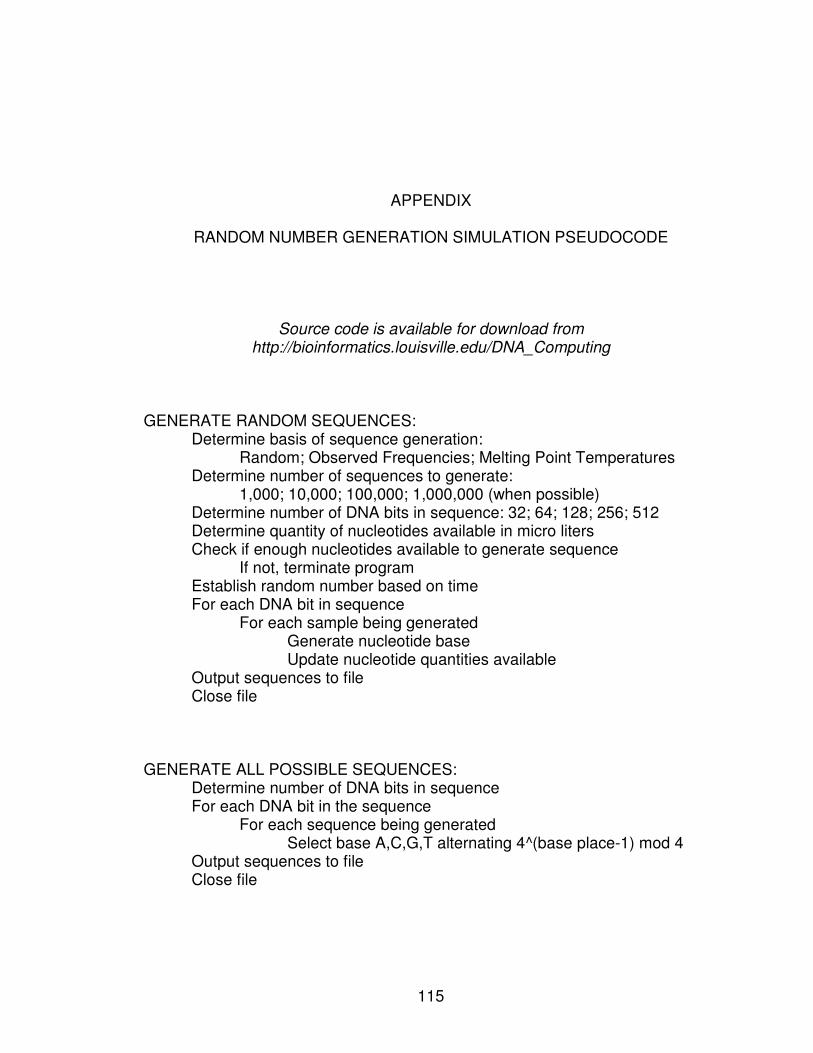
115
APPENDIX
RANDOM NUMBER GENERATION SIMULATION PSEUDOCODE
Source code is available for download from
http://bioinformatics.louisville.edu/DNA_Computing GENERATE RANDOM SEQUENCES: Determine basis of sequence generation:
Random; Observed Frequencies; Melting Point Temperatures Determine number of sequences to generate:
1,000; 10,000; 100,000; 1,000,000 (when possible) Determine number of DNA bits in sequence: 32; 64; 128; 256; 512 Determine quantity of nucleotides available in micro liters Check if enough nucleotides available to generate sequence If not, terminate program Establish random number based on time For each DNA bit in sequence For each sample being generated Generate nucleotide base Update nucleotide quantities available Output sequences to file Close file GENERATE ALL POSSIBLE SEQUENCES: Determine number of DNA bits in sequence For each DNA bit in the sequence For each sequence being generated Select base A,C,G,T alternating 4^(base place-1) mod 4 Output sequences to file Close file
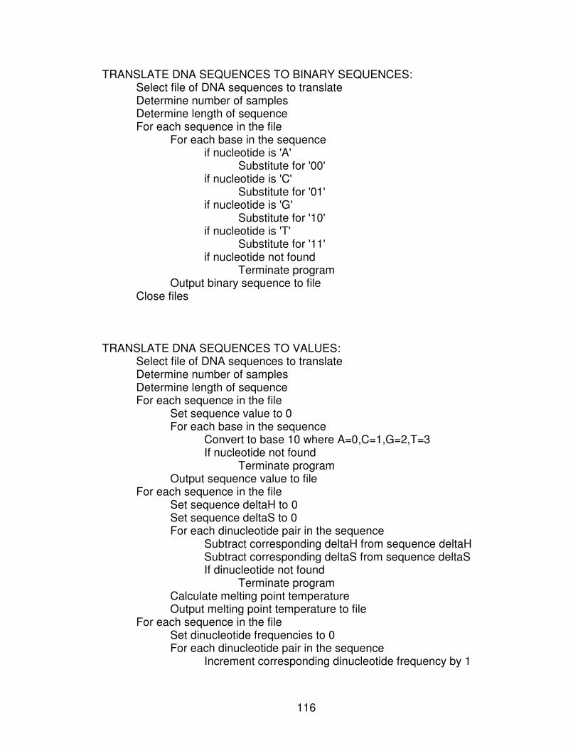
116
TRANSLATE DNA SEQUENCES TO BINARY SEQUENCES: Select file of DNA sequences to translate Determine number of samples Determine length of sequence For each sequence in the file For each base in the sequence if nucleotide is 'A' Substitute for '00' if nucleotide is 'C' Substitute for '01' if nucleotide is 'G' Substitute for '10' if nucleotide is 'T' Substitute for '11' if nucleotide not found Terminate program Output binary sequence to file Close files TRANSLATE DNA SEQUENCES TO VALUES: Select file of DNA sequences to translate Determine number of samples Determine length of sequence For each sequence in the file Set sequence value to 0 For each base in the sequence Convert to base 10 where A=0,C=1,G=2,T=3 If nucleotide not found Terminate program Output sequence value to file For each sequence in the file Set sequence deltaH to 0 Set sequence deltaS to 0 For each dinucleotide pair in the sequence Subtract corresponding deltaH from sequence deltaH Subtract corresponding deltaS from sequence deltaS If dinucleotide not found Terminate program Calculate melting point temperature Output melting point temperature to file For each sequence in the file Set dinucleotide frequencies to 0 For each dinucleotide pair in the sequence Increment corresponding dinucleotide frequency by 1
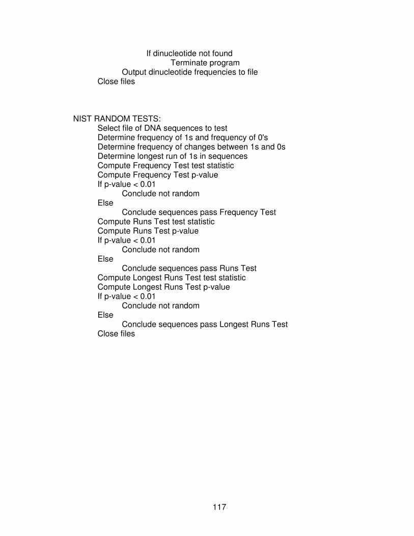
117
If dinucleotide not found Terminate program Output dinucleotide frequencies to file Close files NIST RANDOM TESTS: Select file of DNA sequences to test Determine frequency of 1s and frequency of 0's Determine frequency of changes between 1s and 0s Determine longest run of 1s in sequences Compute Frequency Test test statistic Compute Frequency Test p-value If p-value < 0.01 Conclude not random Else Conclude sequences pass Frequency Test Compute Runs Test test statistic Compute Runs Test p-value If p-value < 0.01 Conclude not random Else Conclude sequences pass Runs Test Compute Longest Runs Test test statistic Compute Longest Runs Test p-value If p-value < 0.01 Conclude not random Else Conclude sequences pass Longest Runs Test Close files
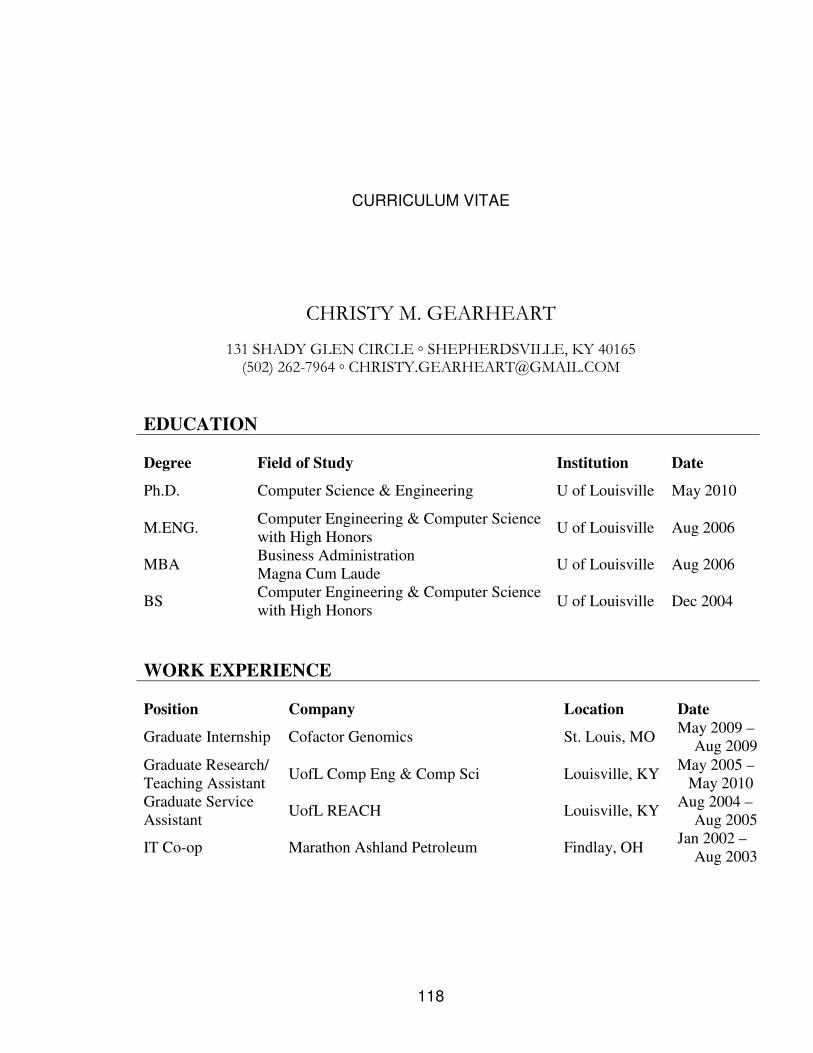
118
CURRICULUM VITAE
CHRISTY M. GEARHEART
131 SHADY GLEN CIRCLE ◦ SHEPHERDSVILLE, KY 40165 (502) 262-7964 ◦ [email protected]
EDUCATION
Degree Field of Study Institution Date
Ph.D. Computer Science & Engineering U of Louisville May 2010
M.ENG. Computer Engineering & Computer Science
with High Honors U of Louisville Aug 2006
MBA Business Administration
Magna Cum Laude U of Louisville Aug 2006
BS Computer Engineering & Computer Science
with High Honors U of Louisville Dec 2004
WORK EXPERIENCE
Position Company Location Date
Graduate Internship Cofactor Genomics St. Louis, MO May 2009 –
Aug 2009
Graduate Research/
Teaching Assistant UofL Comp Eng & Comp Sci Louisville, KY
May 2005 –
May 2010
Graduate Service
Assistant UofL REACH Louisville, KY
Aug 2004 –
Aug 2005
IT Co-op Marathon Ashland Petroleum Findlay, OH Jan 2002 –
Aug 2003
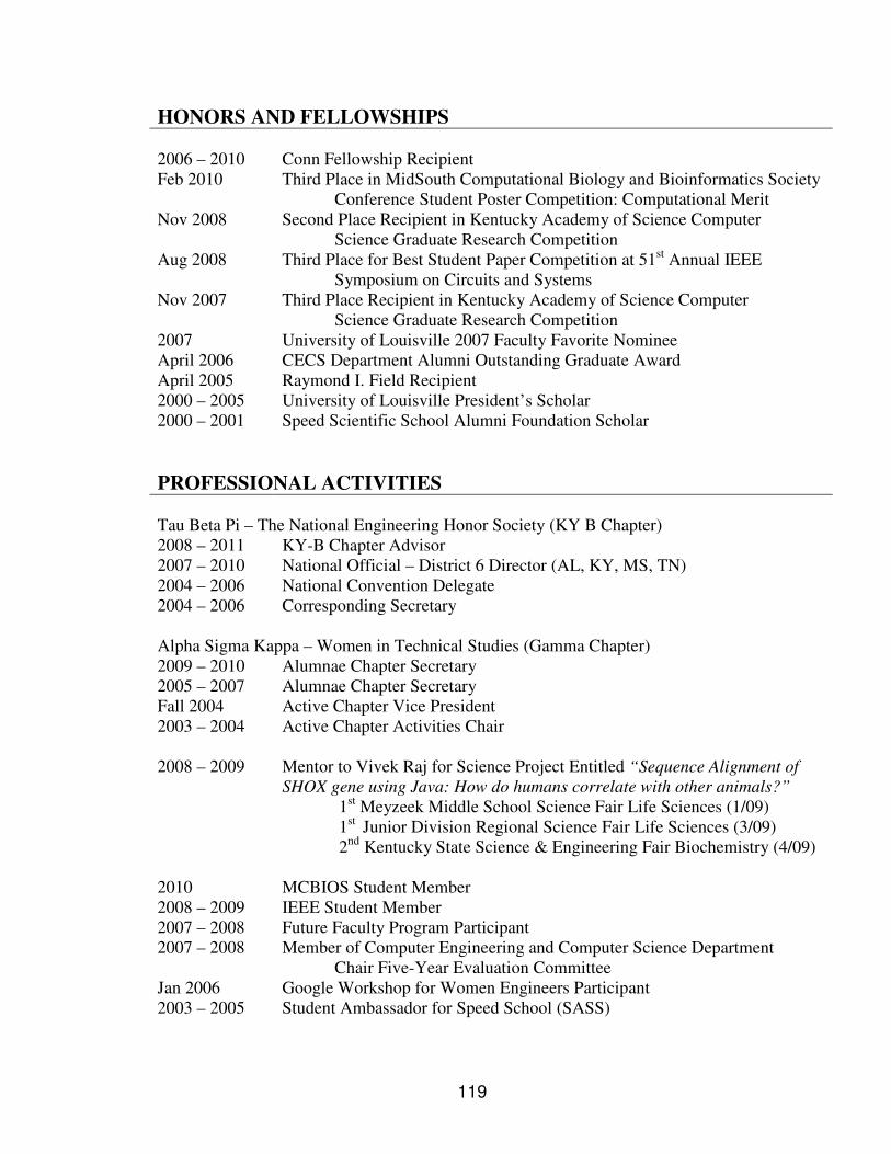
119
HONORS AND FELLOWSHIPS
2006 – 2010 Conn Fellowship Recipient
Feb 2010 Third Place in MidSouth Computational Biology and Bioinformatics Society
Conference Student Poster Competition: Computational Merit
Nov 2008 Second Place Recipient in Kentucky Academy of Science Computer
Science Graduate Research Competition
Aug 2008 Third Place for Best Student Paper Competition at 51st Annual IEEE
Symposium on Circuits and Systems
Nov 2007 Third Place Recipient in Kentucky Academy of Science Computer
Science Graduate Research Competition
2007 University of Louisville 2007 Faculty Favorite Nominee
April 2006 CECS Department Alumni Outstanding Graduate Award
April 2005 Raymond I. Field Recipient
2000 – 2005 University of Louisville President’s Scholar
2000 – 2001 Speed Scientific School Alumni Foundation Scholar
PROFESSIONAL ACTIVITIES
Tau Beta Pi – The National Engineering Honor Society (KY B Chapter)
2008 – 2011 KY-B Chapter Advisor
2007 – 2010 National Official – District 6 Director (AL, KY, MS, TN)
2004 – 2006 National Convention Delegate
2004 – 2006 Corresponding Secretary
Alpha Sigma Kappa – Women in Technical Studies (Gamma Chapter)
2009 – 2010 Alumnae Chapter Secretary
2005 – 2007 Alumnae Chapter Secretary
Fall 2004 Active Chapter Vice President
2003 – 2004 Active Chapter Activities Chair
2008 – 2009 Mentor to Vivek Raj for Science Project Entitled “Sequence Alignment of
SHOX gene using Java: How do humans correlate with other animals?”
1st Meyzeek Middle School Science Fair Life Sciences (1/09)
1st
Junior Division Regional Science Fair Life Sciences (3/09)
2nd
Kentucky State Science & Engineering Fair Biochemistry (4/09)
2010 MCBIOS Student Member
2008 – 2009 IEEE Student Member
2007 – 2008 Future Faculty Program Participant
2007 – 2008 Member of Computer Engineering and Computer Science Department
Chair Five-Year Evaluation Committee
Jan 2006 Google Workshop for Women Engineers Participant
2003 – 2005 Student Ambassador for Speed School (SASS)
120
PEER REVIEWED PUBLICATIONS
C. Gearheart, E. Rouchka, B. Arazi, “DNA-Based Homogenous Logic Design and Its
Applications,” Under Review for BMC Bioinformatics.
C. Gearheart, E. Rouchka, B. Arazi, “DNA-Based Dynamic Logic Circuitry,” Under Review
for 53rd IEEE International Midwest Symposium on Circuits and Systems (MWSCAS).
C. Gearheart, B. Arazi, E. Rouchka, “DNA-Based Random Number Generation in Security
Circuitry,” To Appear in Bio Systems (Accepted March 10, 2010).
C. Bogard, B. Arazi, E. Rouchka, “Toward DNA-Based Security Circuitry: First Step –
Random Number Generation,” 51st Midwest Symposium on Circuits and Systems
(MWSCAS 2008) Knoxville, TN. 2008, pp 597-600.
C. Bogard, E. Rouchka, B. Arazi, “DNA Media Storage,” Progress in Natural Science, Vol
18(5): May 2008, pp 603-609.
C. Bogard, E. Rouchka, B. Arazi, “DNA Media Storage,” The International Conference on
Bio-Inspired Computing: Theories and Applications (BIC-TA 2007) Proceedings.
Zhengzhou, China: Nov 2007, pp 236-239.
C. Bogard, Advancements in Frameworks for Educational Games Through Sound Software
Engineering Principles, M.Eng Thesis, July 2006.
C. Bogard, “Designing Educational Games,” 8th
International Conference on Computer
Games, Artificial Intelligence and Mobile Systems (CGAMES 2006) Proceedings.
Louisville, KY: July 2006, 6 pages on CD.
PRESENTATIONS
Mar 2010 Design of a DNA-Based Shift Register
University of Louisville Graduate Research Symposium Louisville, KY USA
Nov 2009 A Survey of DNA Computing: Data Manipulations
Computer Science & Engineering Seminar Louisville, KY USA
Nov 2008 Towards DNA Computing: First Step – Random Number Generation
Kentucky Academy of Sciences Annual Conference (KAS) Lexington, KY
USA
Second Place in Graduate Research Competition
121
Aug 2008 Towards DNA Computing: First Step – Random Number Generation
51st Annual IEEE International Midwest Symposium on Circuits and
Systems (MWSCAS 2008) Knoxville, TN USA
Third Place in Best Student Paper Competition
Nov 2007 DNA Media Storage
Kentucky Academy of Sciences Annual Conference (KAS) Louisville, KY
USA
Third Place in Computer Science Graduate Research Competition
Sept 2007 DNA Media Storage
International Conference on Bio-Inspired Computing: Theories and
Applications (BIC-TA 2007) Zhengzhou, China
July 2006 Advancements in Frameworks for Educational Games Through Sound
Software Engineering Principles
University of Louisville Computer Engineering & Computer Science
Louisville, KY USA
July 2006 Designing Educational Games
International Conference on Computer Games, Artificial Intelligence, and
Mobile Systems (CGAMES 2006) Louisville, KY USA
POSTER PRESENTATIONS
C. Gearheart, E. Rouchka, B. Arazi, “Design of a DNA-Based Shift Register” UT-ORNL-
KBRIN Bioinformatics Summit 2010, Cadiz, KY, Mar 2010, Cadiz, KY
C. Gearheart, E. Rouchka, B. Arazi, “Design of a DNA-Based Shift Register” The Seventh
Annual Conference of the MidSouth Computational Bioloy and Bioinformatics Society
(MCBIOS VII), Feb 2010, Jonesboro, AR.
Third Place in Student Poster Competition: Computational Merit
C. Bogard, B. Arazi, E. Rouchka, “Simulation of a DNA-Based Random Number
Generation,” DNA15 The 15th
International Meeting on DNA Computing and
Molecular Programming, June 2009, Fayetteville, AR.
C. Bogard, B. Arazi, E. Rouchka, “Toward DNA-based Security Circuitry: First Step –
Random Number Generation,” UT-ORNL-KBRIN Bioinformatics Summit 2008, Cadiz,
KY, Apr 2008, Cadiz, KY.
C. Bogard, E. Rouchka, B. Arazi, “DNA Media Storage,” University of Louisville Speed
School of Engineering E-Expo 2008, Mar 2008, Louisville, KY.
C. Bogard, E. Rouchka, B. Arazi, “DNA Media Storage,” Kentucky Biomedical Research
Infrastructure Network (KBRIN) Semi-Annual Meeting, Dec 2007, Louisville, KY.
122
CONFERENCES ATTENDED
Mar 2010 UT-ORNL-KBRIN Bioinformatics Summit 2010, Cadiz, KY
Feb 2010 The Seventh Annual Conference of the MidSouth Computational Bioloy and
Bioinformatics Society (MCBIOS VII), Feb 2010, Jonesboro, AR
June 2009 15th
International Meeting on DNA Computing and Molecular Programming
(DNA15), Fayetteville, AR
Mar 2009 UT-ORNL-KBRIN Bioinformatics Summit 2009, Pikeville, TN
Nov 2008 Kentucky Academy of Sciences (KAS), Lexington, KY
Aug 2008 51st Annual IEEE International Symposium on Circuits and Systems,
Knoxville, TN
May 2008 2008 IEEE Symposium on Security and Privacy (SP08), Oakland, CA
Apr 2008 UT-ORNL-KBRIN Bioinformatics Summit 2008, Cadiz, KY
Nov 2007 Kentucky Academy of Sciences (KAS), Louisville, KY
Sept 2007 International Conference Bio-Inspired Computing: Theories and
Applications (BIC-TA 2007), Zhengzhou, China
May 2007 Indy Regional Bioinformatics Conference (Indy ’07), Indianapolis, IN
Apr 2007 UT-ORNL-KBRIN Bioinformatics Summit 2007, Buchanan, TN
July 2006 International Conference on Computer Games, Artificial Intelligence, and
Mobile Systems (CGAMES 2006), Louisville, KY
RELEVANT COURSEWORK
Artificial Intelligence Design of Computer Algorithms
Algebraic Statistics for Genetics and Molecular Biology
Computational Biology Human Computer Interaction
Bioinformatics Hypertext and Multimedia
College Teaching Network Security
Combinatorial Optimization Performance Evaluations of
Computer Forensics Computer Systems
Cryptography Project Management
Data Mining Simulation of Discrete Systems
Design of Compilers Web Mining
123
REFERENCES
Dr. Eric C. Rouchka Doctoral Advisor and Assistant Professor
Computer Engineering & Computer Science
Duthie Center for Engineering
University of Louisville
Louisville, Kentucky 40292
502-852-1695
Dr. Jarret Glasscock Chief Technical Officer
Cofactor Genomics
3141 Olive Street
St Louis, Missouri 63103
314-952-5834
Dr. Adel Elmaghraby Department Chair
Computer Engineering & Computer Science
Duthie Center for Engineering
University of Louisville
Louisville, Kentucky 40292
502-852-0470