Embed Size (px)
DESCRIPTION
Design Basis report of Chennai Metro
Citation preview
General Consultants for Chennai Metro Rail
Project, Phase - I
DESIGN BASIS REPORT
CHENNAI METRO RAIL LIMITED METRO RAIL PROJECT – PHASE - I
VOLUME – 5
PART – II
DMRC’S DESIGN BASIS REPORT FOR VIADUCT
(APRIL 2009)
DMRC’s Design Basis Report For Viaduct (April 2009)
CHENNAI METRO RAIL CORPORATION LIMITED
ELEVATED VIADUCT DESIGN BASIS REPORT
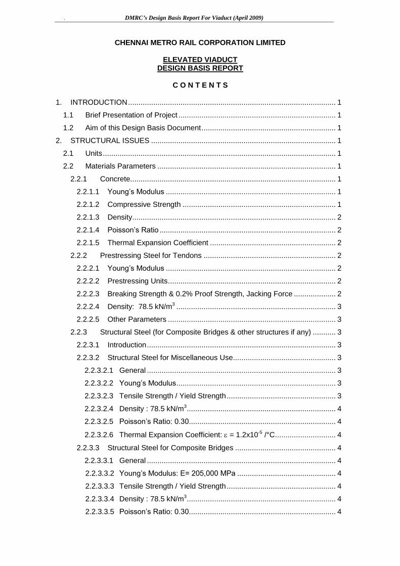
C O N T E N T S
1. INTRODUCTION ................................................................................................... 1
1.1 Brief Presentation of Project ........................................................................... 1
1.2 Aim of this Design Basis Document ................................................................ 1
2. STRUCTURAL ISSUES ........................................................................................ 1
2.1 Units ............................................................................................................... 1
2.2 Materials Parameters ..................................................................................... 1
2.2.1 Concrete.................................................................................................. 1
2.2.1.1 Young‟s Modulus ................................................................................. 1
2.2.1.2 Compressive Strength ......................................................................... 1
2.2.1.3 Density................................................................................................. 2
2.2.1.4 Poisson‟s Ratio .................................................................................... 2
2.2.1.5 Thermal Expansion Coefficient ............................................................ 2
2.2.2 Prestressing Steel for Tendons ............................................................... 2
2.2.2.1 Young‟s Modulus ................................................................................. 2
2.2.2.2 Prestressing Units ................................................................................ 2
2.2.2.3 Breaking Strength & 0.2% Proof Strength, Jacking Force .................... 2
2.2.2.4 Density: 78.5 kN/m3 ............................................................................ 3
2.2.2.5 Other Parameters ................................................................................ 3
2.2.3 Structural Steel (for Composite Bridges & other structures if any) ........... 3
2.2.3.1 Introduction .......................................................................................... 3
2.2.3.2 Structural Steel for Miscellaneous Use................................................. 3
2.2.3.2.1 General .......................................................................................... 3
2.2.3.2.2 Young‟s Modulus ............................................................................ 3
2.2.3.2.3 Tensile Strength / Yield Strength .................................................... 3
2.2.3.2.4 Density : 78.5 kN/m3 ....................................................................... 4
2.2.3.2.5 Poisson‟s Ratio: 0.30 ...................................................................... 4
2.2.3.2.6 Thermal Expansion Coefficient: = 1.2x10⁻⁵ /°C ............................. 4
2.2.3.3 Structural Steel for Composite Bridges ................................................ 4
2.2.3.3.1 General .......................................................................................... 4
2.2.3.3.2 Young‟s Modulus: E= 205,000 MPa ............................................... 4
2.2.3.3.3 Tensile Strength / Yield Strength .................................................... 4
2.2.3.3.4 Density : 78.5 kN/m3 ....................................................................... 4
2.2.3.3.5 Poisson‟s Ratio: 0.30 ...................................................................... 4
DMRC’s Design Basis Report For Viaduct (April 2009)
2.2.3.3.6 Thermal Expansion Coefficient: = 1.2x10⁻⁵ /°C ............................. 4
2.2.4 Reinforcement Steel (Rebars) ................................................................. 4
2.2.4.1 Young‟s Modulus: E= 200,000 MPa ..................................................... 4
2.2.4.2 Yield Stress: fy = 415 MPa. .................................................................. 4
2.2.4.3 Diameters [in mm]: 6, 8, 10, 12, 16, 20, 25, 28, 32, & 36...................... 5
2.2.4.4 Density: 78.5 kN/m3 ............................................................................. 5
2.3 Time-Dependent Characteristics of Materials ................................................. 5
2.4 Clearances ..................................................................................................... 5
2.4.1 Clearance for Road Traffic ...................................................................... 5
2.4.2 Clearances for Rolling Stock ................................................................... 5
2.4.2.1 Vertical Clearance ............................................................................... 5
2.4.2.2 Horizontal Clearance ........................................................................... 6
2.5 Seismic Design ............................................................................................... 6
2.5.1.1 General Principle ................................................................................. 6
2.5.1.2 Fundamental Vibration Period Calculation ........................................... 6
2.5.1.3 Response Spectrum Definition ............................................................. 7
2.5.1.3.1 Basic Design Response Spectrum ................................................. 7
2.5.1.3.2 Seismic Acceleration ...................................................................... 7
2.5.1.4 Vertical Seismic ................................................................................... 8
2.5.1.5 Seismic Combinations ......................................................................... 8
2.6 Vertical Deflections at Mid-Span ..................................................................... 8
2.7 Live Loads: Train & Footpath .......................................................................... 8
2.7.1 Vertical Train Live Load ........................................................................... 8
2.7.2 Horizontal Train Live Load ....................................................................... 9
2.7.2.1 Braking and Traction ............................................................................ 9
2.7.2.2 Centrifugal Force ................................................................................. 9
2.7.3 Footpath Live Load .................................................................................. 9
2.8 Coefficient of Dynamic Impact (CDA) ............................................................. 9
2.9 Superimposed Dead Loads (SIDL) ................................................................. 9
2.10 Emergency Walkway on Viaducts................................................................. 10
2.11 Overall Temperature..................................................................................... 10
2.12 Differential Temperature ............................................................................... 10
2.13 Differential Settlement .................................................................................. 10
2.14 LWR Forces ................................................................................................. 10
2.15 Elementary Loads Definition ......................................................................... 11
2.16 Load Combinations Methodology ................................................................. 12
2.17 Allowable Stresses in Superstructures (SLS Check)..................................... 13
2.17.1 Precast Segmental Simple Spans (SLS Check) .................................... 13
DMRC’s Design Basis Report For Viaduct (April 2009)
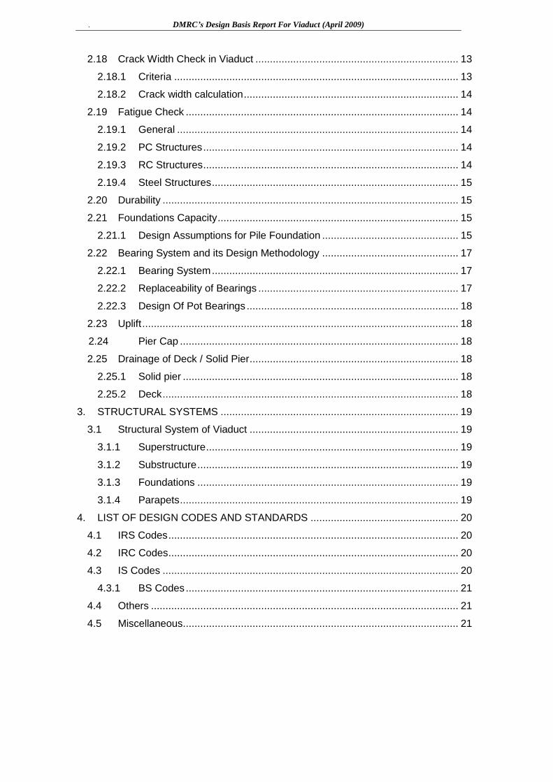
2.18 Crack Width Check in Viaduct ...................................................................... 13
2.18.1 Criteria .................................................................................................. 13
2.18.2 Crack width calculation .......................................................................... 14
2.19 Fatigue Check .............................................................................................. 14
2.19.1 General ................................................................................................. 14
2.19.2 PC Structures ........................................................................................ 14
2.19.3 RC Structures ........................................................................................ 14
2.19.4 Steel Structures ..................................................................................... 15
2.20 Durability ...................................................................................................... 15
2.21 Foundations Capacity ................................................................................... 15
2.21.1 Design Assumptions for Pile Foundation ............................................... 15
2.22 Bearing System and its Design Methodology ............................................... 17
2.22.1 Bearing System ..................................................................................... 17
2.22.2 Replaceability of Bearings ..................................................................... 17
2.22.3 Design Of Pot Bearings ......................................................................... 18
2.23 Uplift ............................................................................................................. 18
2.24 Pier Cap ................................................................................................ 18
2.25 Drainage of Deck / Solid Pier ........................................................................ 18
2.25.1 Solid pier ............................................................................................... 18
2.25.2 Deck ...................................................................................................... 18
3. STRUCTURAL SYSTEMS .................................................................................. 19
3.1 Structural System of Viaduct ........................................................................ 19
3.1.1 Superstructure ....................................................................................... 19
3.1.2 Substructure .......................................................................................... 19
3.1.3 Foundations .......................................................................................... 19
3.1.4 Parapets ................................................................................................ 19
4. LIST OF DESIGN CODES AND STANDARDS ................................................... 20
4.1 IRS Codes .................................................................................................... 20
4.2 IRC Codes .................................................................................................... 20
4.3 IS Codes ...................................................................................................... 20
4.3.1 BS Codes .............................................................................................. 21
4.4 Others .......................................................................................................... 21
4.5 Miscellaneous............................................................................................... 21

DMRC’s Design Basis Report For Viaduct (April 2009)
1
1. INTRODUCTION
1.1 Brief Presentation of Project
- This design basis report pertains to the viaduct portions of the Chennai Metro Phase-I project.
1.2 Aim of this Design Basis Document
This design basis note is being submitted highlighting the proposed design methodology for the project. All design works, cost estimates and BOQ calculations shall be performed taking into consideration this Design Basis Report.
2. STRUCTURAL ISSUES
2.1 Units
The main units used for design will be: [t], [m], [mm], [kN], [KN/m2], [MPa], [°C], [rad]
2.2 Materials Parameters
2.2.1 Concrete
2.2.1.1 Young’s Modulus
a) Instantaneous modulus: E is given as § 5.2.2.1 of IRS- CBC-1999:
For fck = 60 MPa Ei = 36,000 MPa (given in IRS-CBC)
For fck = 50 MPa Ei = 34,000 MPa (given in IRS-CBC)
For fck = 45 MPa Ei = 32,500 MPa (interpolated)
For fck = 35 MPa Ei = 29,500 MPa (interpolated)
b) Modular Ratio: Modular ratio for all concrete grades shall be taken as 10.
2.2.1.2 Compressive Strength
Durability provisions for structures shall be as per “severe” conditions of environment in accordance with IRS CBC: 1997, clause 5.4 (also refer Correction Slip No-1 dated 26.04-2000).
Keeping the durability and structural requirement, the proposed strength of various elements of structure will be as follows: - precast segmental box section fck = 50 MPa / 45 MPa - for pier (shaft & pier cap) fck = 45 MPa / 50 MPa/ 60 MPa - for bearing pad (mortar) fck = 75 MPa - for piles & pile cap fck = 30 MPa
DMRC’s Design Basis Report For Viaduct (April 2009)
2
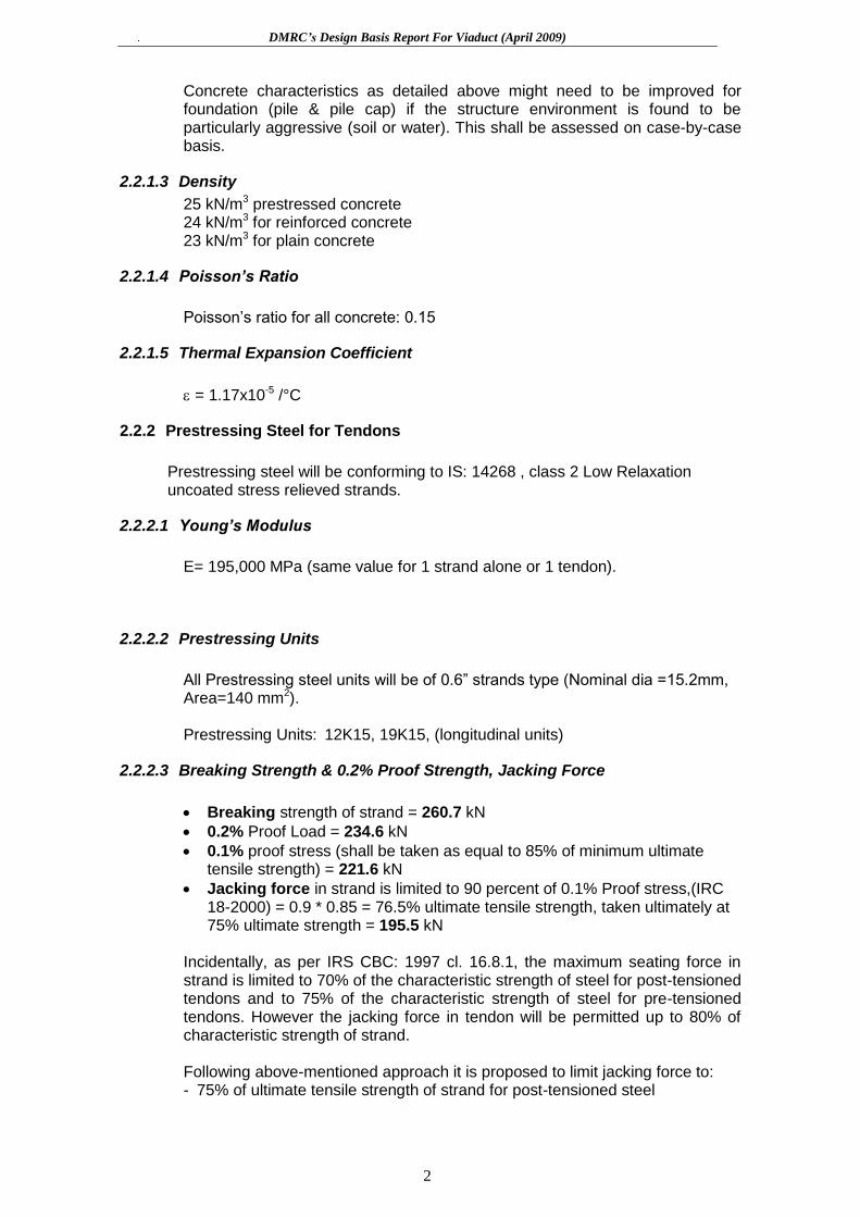
Concrete characteristics as detailed above might need to be improved for foundation (pile & pile cap) if the structure environment is found to be particularly aggressive (soil or water). This shall be assessed on case-by-case basis.
2.2.1.3 Density
25 kN/m3 prestressed concrete 24 kN/m3 for reinforced concrete 23 kN/m3 for plain concrete
2.2.1.4 Poisson’s Ratio
Poisson‟s ratio for all concrete: 0.15
2.2.1.5 Thermal Expansion Coefficient
= 1.17x10⁻⁵ /°C
2.2.2 Prestressing Steel for Tendons
Prestressing steel will be conforming to IS: 14268 , class 2 Low Relaxation uncoated stress relieved strands.
2.2.2.1 Young’s Modulus
E= 195,000 MPa (same value for 1 strand alone or 1 tendon).
2.2.2.2 Prestressing Units
All Prestressing steel units will be of 0.6” strands type (Nominal dia =15.2mm, Area=140 mm2). Prestressing Units: 12K15, 19K15, (longitudinal units)
2.2.2.3 Breaking Strength & 0.2% Proof Strength, Jacking Force
Breaking strength of strand = 260.7 kN
0.2% Proof Load = 234.6 kN
0.1% proof stress (shall be taken as equal to 85% of minimum ultimate tensile strength) = 221.6 kN
Jacking force in strand is limited to 90 percent of 0.1% Proof stress,(IRC 18-2000) = 0.9 * 0.85 = 76.5% ultimate tensile strength, taken ultimately at 75% ultimate strength = 195.5 kN
Incidentally, as per IRS CBC: 1997 cl. 16.8.1, the maximum seating force in strand is limited to 70% of the characteristic strength of steel for post-tensioned tendons and to 75% of the characteristic strength of steel for pre-tensioned tendons. However the jacking force in tendon will be permitted up to 80% of characteristic strength of strand.
Following above-mentioned approach it is proposed to limit jacking force to: - 75% of ultimate tensile strength of strand for post-tensioned steel

DMRC’s Design Basis Report For Viaduct (April 2009)
3
2.2.2.4 Density: 78.5 kN/m3
2.2.2.5 Other Parameters
Sheathing Corrugated HDPE Duct 107 mm (E 1 mm
tolerance) ID Anchorage set-in 6 mm
Friction (wobble) 0.0025 m-1
For cables with plan curvature, above value will be enhanced by 10% Friction (curvature) 0.17 rad-1
2.2.3 Structural Steel (for Composite Bridges & other structures if any)
2.2.3.1 Introduction
Structural steel will be used for special composite bridges and for miscellaneous use such as railing, supporting utilities, coverings etc.
2.2.3.2 Structural Steel for Miscellaneous Use
2.2.3.2.1 General
Two types of structural steel are proposed as per the following standards:
a) IS: 4923 “Hollow steel sections for structural use with Yst 310” b) IS: 2062 “Steel for General Structural Purposes (Grade B-Designation
410B)”
The hollow steel sections would be square (SHS) or rectangular (RHS). Other traditional rolled sections like plates, angles, channels, joists would also be used where necessary.
The base connections and connection with concrete shall be effected by internally threaded bolt sleeves (hot dipped galvanized @ 300 gm/ sqm) manufactured from IS: 2062 Grade B mild steel. The sleeve shall receive hexagon-head bolt M20 Class 8.8 as per IS: 1364 (Part 1) with galvanized spring washer. The connections within the steel structure would be effected essentially by direct welding of members with/ without gusset plates. The minimum thickness of metal for SHS/RHS sections for main chord members as well bracings shall be 4mm as applicable for steel tubes in clause 6.3 of IS: 806. Structural steel conforming to Grade Fe540HT as per IS: 8500 will be adopted in case high strength steel is required.
2.2.3.2.2 Young’s Modulus
E= 200,000 MPa
2.2.3.2.3 Tensile Strength / Yield Strength
For Hollow steel sections (conforming to IS: 4923)
Tensile strength shall be 450 Mpa;
DMRC’s Design Basis Report For Viaduct (April 2009)
4
Yield strength shall be 310Mpa.
For Structural Steel (Conforming to IS: 2062):
Tensile strength shall be 410 Mpa;
Yield strength shall be 250Mpa (for t<20mm), 240Mpa (for 20mm < t < 40mm) 230Mpa (for t > 40mm)
2.2.3.2.4 Density: 78.5 kN/m3
2.2.3.2.5 Poisson’s Ratio: 0.30
2.2.3.2.6 Thermal Expansion Coefficient: = 1.2x10⁻⁵ /°C
2.2.3.3 Structural Steel for Composite Bridges
2.2.3.3.1 General
The connections between steel members will be either bolted or/and welded. Welded connections are preferable. The design will be performed for one solution only, to be chosen and discussed according to the availability of contractor‟s expertise.
2.2.3.3.2 Young’s Modulus: E= 205,000 MPa
2.2.3.3.3 Tensile Strength / Yield Strength
ASTM A572 Grade 50 with a minimum guaranteed notched bar impact strength (Charpy energy) required at -20°c: 47 J
Fy = 350 MPa for t 100 mm
2.2.3.3.4 Density: 78.5 kN/m3
2.2.3.3.5 Poisson’s Ratio: 0.30
2.2.3.3.6 Thermal Expansion Coefficient: = 1.2x10⁻⁵ /°C
2.2.4 Reinforcement Steel (Rebars)
Only Thermo-mechanically treated reinforcement bars of grade Fe 500 (min.) conforming to IS: 1786 will be adopted. The extruded steel bars shall be out of billets and not out of scrap steel. The reinforcement steel bars manufactured in re-rolling mills shall not be procured under any circum stances. The steel bars manufactured by approved firms alone shall be procured and used for the structures.
Young‟s Modulus: E= 200,000 Mpa
Yield Stress: fy = 500 MPa.

DMRC’s Design Basis Report For Viaduct (April 2009)
5
2.2.4.1 Diameters [in mm]: 6, 8, 10, 12, 16, 20, 25, 28, 32, & 36.
2.2.4.2 Density: 78.5 kN/m3
2.3 Time-Dependent Characteristics of Materials
As the spans are to be constructed by precast segmental construction, the post-tensioning will be applied after the concrete has achieved its specified 28-days strength. Long-term losses will be calculated in accordance with IRS CBC 1997. Special
Purpose Software like ADAPT ABI may be used for continuous spans if any.
2.4 Clearances
2.4.1 Clearance for Road Traffic
5.50m at 0.475m (0.45m (width of the 1m-high Jersey-type crash barrier) +
0.025m (clearance between crash barrier and pier shaft)) from pier shaft outer
line.
2.4.2 Clearances for Rolling Stock
2.4.2.1 Vertical Clearance
Note that:
- The minimum plinth thickness is assumed as 195mm.
- The distance between top of rail and top of plinth is assumed as 219mm.
2100 mm 1090 mm
0.475m 0.475m
Road level Road finish level
5.500m 5.500m
Lower Rail
level
Parapet Top Level
DMRC’s Design Basis Report For Viaduct (April 2009)
6
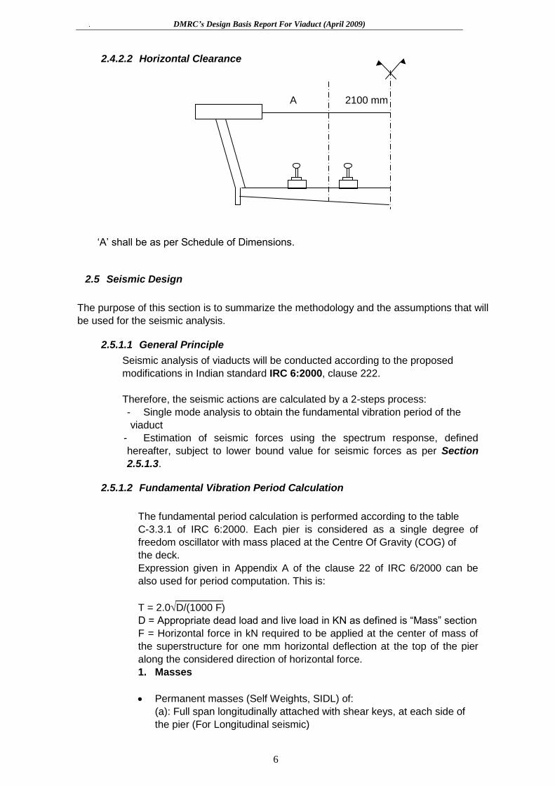
2.4.2.2 Horizontal Clearance
A 2100 mm
„A‟ shall be as per Schedule of Dimensions.
2.5 Seismic Design
The purpose of this section is to summarize the methodology and the assumptions that will
be used for the seismic analysis.
2.5.1.1 General Principle
Seismic analysis of viaducts will be conducted according to the proposed
modifications in Indian standard IRC 6:2000, clause 222.
Therefore, the seismic actions are calculated by a 2-steps process:
- Single mode analysis to obtain the fundamental vibration period of the
viaduct
- Estimation of seismic forces using the spectrum response, defined
hereafter, subject to lower bound value for seismic forces as per Section
2.5.1.3.
2.5.1.2 Fundamental Vibration Period Calculation
The fundamental period calculation is performed according to the table
C-3.3.1 of IRC 6:2000. Each pier is considered as a single degree of
freedom oscillator with mass placed at the Centre Of Gravity (COG) of
the deck.
Expression given in Appendix A of the clause 22 of IRC 6/2000 can be
also used for period computation. This is:
T = 2.0D/(1000 F)
D = Appropriate dead load and live load in KN as defined is “Mass” section
F = Horizontal force in kN required to be applied at the center of mass of
the superstructure for one mm horizontal deflection at the top of the pier
along the considered direction of horizontal force.
1. Masses
Permanent masses (Self Weights, SIDL) of:
(a): Full span longitudinally attached with shear keys, at each side of
the pier (For Longitudinal seismic)
DMRC’s Design Basis Report For Viaduct (April 2009)
7
(b): Half of spans on either side of pier (For Transverse seismic)
Mass of the pier cap (neglecting Shear-Key)
Mass of the top half of the pier
25% of Train mass will be considered while evaluating time period /
forces due to seismic in transverse direction. This percentage is only for
working out the magnitude of seismic force. Train mass shall not be
considered when acting in the direction of traffic i.e. longitudinal direction.
In both the seismic conditions (longitudinal as well as transverse), for
calculating the stresses due to vertical effect of live load, 50% of the
design live load shall be considered at the time of earthquake.
As per IRS Bridge Rules, correction slip no.22 dated 17 / 1 / 1994, in
transverse/ longitudinal seismic condition, only 50% of gross tractive effort
/ braking force will be considered.
2. Stiffness
Stiffness shall be calculated with the uncracked section characteristics
and with the concrete instantaneous modulus of elasticity, for all structural
elements.
Effect of the foundation system (pile-cap + piles + soil) in the flexibility
of the substructure is considered by a set of equivalent springs added
simulating pile-soil interaction (for details refer to pile stiffness
calculation).
2.5.1.3 Response Spectrum Definition
All numerical values mentioned in this chapter are based on a 5% damping
ratio, which will be used for the design.
2.5.1.3.1 Basic Design Response Spectrum
Response spectrum used for seismic calculation shall be as per (IS 1893
(part1) 2001), reproduced in IRC 6:2000.
2.5.1.3.2 Seismic Acceleration
Sa/g being computed by the relevant IRC:6 seismic acceleration can then
be calculated by:
Ah = (Z/2) * (I/R) * (Sa/g), where:
Ah = horizontal seismic coefficient to be considered in design.
(Seismic acceleration = Ah*g)
Z = Zone factor = 0.16 (Chennai region = zone III)
I = Importance factor = 1.5
R = Reduction factor = 2.5
As a result:
Ah = 0.048 *(Sa/g)

DMRC’s Design Basis Report For Viaduct (April 2009)
8
For reference, at the peak of the spectrum for 0.0 < T < 0.55 then:
Ah max = 0.048 * 2.5 = 0.12
Therefore 0.12g is the maximum acceleration that can be considered in
the design.
2.5.1.4 Vertical Seismic
The vertical seism will be taken as half of the horizontal seismic coefficient
(Ah).
Av = Ah/2
2.5.1.5 Seismic Combinations
As per IRC 6: 2000, the following seismic combinations will be considered:
a) Sx Sy
b) Sz Sy
Sx : Seismic force calculated by Ah in X direction ( x, axis of the project)
Sz : seismic force calculated by Ah in Z direction ( Z , transverse direction)
Sy: Vertical seism calculated by Av
2.6 Vertical Deflections at Mid-Span
Vertical deflection limit for PSC girders supporting tracks, under Live Load + dynamic
impact:
L/2400 (L =span length)
Vertical deflection limit for composite steel girder – concrete deck supporting tracks,
under Live Load + dynamic impact: L/1800 (L =span length)
2.7 Live Loads: Train & Footpath
2.7.1 Vertical Train Live Load
Each component of the structure shall be designed/checked for all possible combinations of
these loads and forces. They shall resist the effect of the worst combination:
All axle loads = 16 tons
Maximum number of successive cars = 6
Where,
a b c b a
DMRC’s Design Basis Report For Viaduct (April 2009)
9
L = 21300 (Length of a car)
a = 2150 (Overhang)
b = 2300 (Wheel base in a bogie)
c = 12400 (Distance between Axle-2 and Axle-3 in the car)
Maximum number of axles will be loaded on the superstructure to arrive at maximum
longitudinal force, max shear and max BM. Since both the tracks will be supported
by single box girder, hence superstructure, bearing and substructure will be checked
for one track loaded condition as well as both track loaded condition.
2.7.2 Horizontal Train Live Load
2.7.2.1 Braking and Traction
Braking load is taken as 15% of the unfactored vertical loads.
Traction load is taken as 18% of the unfactored vertical loads.
Since both the tracks are supported by a single girder, hence tractive force of one track
and braking force of another track will be taken in the same direction to produce worst
condition of loading.
As per IRS Bridge Rules, correction slip no.22 dated 17 / 1 / 1994, in transverse/
longitudinal seismic condition, only 50% of gross tractive effort / braking force will be
considered.
2.7.2.2 Centrifugal Force
Design Speed for various radii of curvature shall be as stipulated in Schedule of
Dimension.
2.7.3 Footpath Live Load
Footpath live load shall be adopted as 490 kg/m2. As footpath live load is to be
considered with carriageway live load without impact, this load will not be critical for any
design except the parapet.
2.8 Coefficient of Dynamic Impact (CDA)
Impact factor for longitudinal analysis shall be 1.2 while for transverse analysis the
same shall be 1.67.
2.9 Superimposed Dead Loads (SIDL)
Superimposed dead load will be 7.5 Metric tons/m.
It is highlighted that the design of concrete block underneath the rail, connection
of rail fastening with the concrete block and design of shear connectors between

DMRC’s Design Basis Report For Viaduct (April 2009)
10
super structure & track bed are excluded from the present consultancy
assignment.
2.10 Emergency Walkway on Viaducts
The proposed minimum width of parapet top flange is 1200mm.
2.11 Overall Temperature
An overall differential temperature of ±25°C (difference between construction
temperature and maximum/minimum coming temperature) will be considered.
2.12 Differential Temperature
For PSC box section, following temperature gradient will be considered for
design:
(a) 8 oC gradient across depth of box
(b) 5 oC inside the box
(c) 5 oC outside the box
2.13 Differential Settlement
Differential settlement between two adjacent viaduct piers will be:
12 mm for Long Term Settlement;
6 mm for Short Term Settlement
Differential settlement is to be considered only in the design of continuous
structures, if any.
LWR Forces
Appropriate horizontal load will be considered in the longitudinal direction as per
the Rail Structure interaction analysis depending on the fastening system
1200 min.
(top fiber)
DMRC’s Design Basis Report For Viaduct (April 2009)
11
adopted. This load will be considered with live loads but without seismic loads.
The methodology for computation of loads due to LWR shall be as per UIC-774.
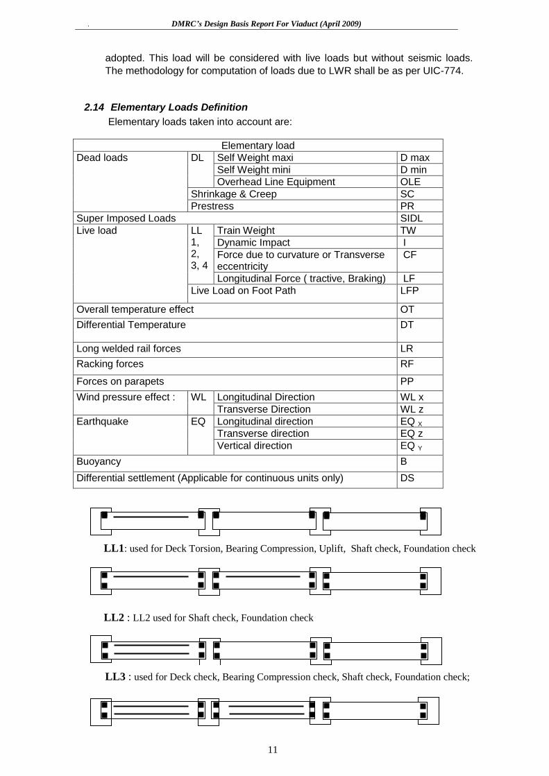
2.14 Elementary Loads Definition
Elementary loads taken into account are:
Elementary load
Dead loads DL
Self Weight maxi D max
Self Weight mini D min
Overhead Line Equipment OLE
Shrinkage & Creep SC
Prestress PR
Super Imposed Loads SIDL
Live load LL 1, 2, 3, 4
Train Weight TW
Dynamic Impact I
Force due to curvature or Transverse eccentricity
CF
Longitudinal Force ( tractive, Braking) LF
Live Load on Foot Path LFP
Overall temperature effect OT
Differential Temperature
DT
Long welded rail forces LR
Racking forces RF
Forces on parapets PP
Wind pressure effect : WL Longitudinal Direction WL x
Transverse Direction WL z
Earthquake EQ Longitudinal direction EQ X
Transverse direction EQ z
Vertical direction EQ Y
Buoyancy B
Differential settlement (Applicable for continuous units only) DS
LL1: used for Deck Torsion, Bearing Compression, Uplift, Shaft check, Foundation check
LL3 : used for Deck check, Bearing Compression check, Shaft check, Foundation check;
LL2 : LL2 used for Shaft check, Foundation check

DMRC’s Design Basis Report For Viaduct (April 2009)
12
2.15 Load Combinations Methodology
In each of SLS and ULS cases, 5 basic load combination groups, according to the
IRS- CBC, Second Revision,1997, Table-12 modified to the extent by the
contents of letter no. DMRC/Corp/20/Design/312/2005 dated 13 Sep 2005 are
considered. Due to the SHEAR-KEY, withstanding the horizontal forces,
combination group IV is eliminated. This combination case deals only with friction
forces on deck that is avoided by shear-keys.
Limit
State
Loads Symbol G I G II G III G V
Cracking +
Stress
G II a
Stress
G II b
Stress
Stress Stress
SL
S C
OM
BIN
AT
ION
S
Dead Loads DL 1.00 1.00 1.00 1.00 1.00
Shrinkage &
Creep
SC 1.00 1.00 1.00 1.00 1.00
Prestressing PR 1.00 1.00 1.00 1.00 1.00
Super Imposed
Loads
SIDL 1.20 1.20 1.20 1.20 1.00
Earth quake (**) EQ 1.00 1.00
Overall T (***) OT 1.00
Differential
Temperature
DT 0.80
Differential
settlement
DS 1.00
Live Load LL 1.00 1.00 1.00
Derailment Loads DR 1.00
UL
S C
OM
BIN
AT
ION
S
Dead Loads DL 1.35 1.35 1.35
Not to
be c
onsid
ere
d,
Per
IRS
: C
BC
CI 1
0.3
.1
1.35
Prestressing PR 1.15/0.87 (*) 1.15/0.87 (*) 1.15/0.87 (*) 1.15/0.87
(*)
Super Imposed
Loads
SIDL 1.35 1.35 1.35 1.35
Earth quake (**) EQ 1.60 1.25
Live Load LL 1.5 1.5
Derailment Loads DR 1.75
(*) 1.15/0.87 : according to IRS CBC art. 11.3.3., when the Prestressing PR increases
the section capacity vs. shear then PR is multiplied by 0.87. When the Prestressing PR
decreases the section capacity vs. shear then PR is multiplied by 1.15.
(**) It should be noted that temperature load case is never combined with seismic
loading.
50% LL effects (LL + LFP) have to be considered along with G II & GIII.
Structure has to be checked with appropriate Prestressing value, i.e. at construction and
at “infinity” stage (i.e. Year 120)
LL4: used for shaft check, Foundation check, Shear Key check

DMRC’s Design Basis Report For Viaduct (April 2009)
13
2.16 Allowable Stresses in Superstructures (SLS Check)
2.16.1 Precast Segmental Simple Spans (SLS Check)
No Load
Combination
Allowable
compressive
strength
Reference Allowable
Tensile
stress
Reference
At transfer and/or Construction stage, (In line with IRC: 6-2000)
1 DL + *DS +
App. PR
0.5 fci but <0.4 fck Cl 16.4.2.2(b) of
IRS CBC 1997
No tension
anywhere
2 Group 1+
50% EL
0.5 fci but <0.4 fck (Cl 16.4.2.2(b) of
IRS CBC 1997)
No tension
anywhere
During Service
3 SLS GI 0.4 fck (Cl. 16.4.2.2 (a)
of IRS CBC 1997
No tension
anywhere
Note 2 under
Table 11, IRS
CBC 1997,
and cl 17.3.3)
4 SLS GII 0.4 fck (Cl. 16.4.2.2 (a)
of IRS CBC 1997
No tension
anywhere
Note 2 under
Table 11, IRS
CBC 1997,
and cl 17.3.3)
5 SLS GIII 0.4 fck (Cl. 16.4.2.2 (a)
of IRS CBC 1997
No tension
anywhere
Note 2 under
Table 11, IRS
CBC 1997,
and cl 17.3.3)
Ultimate Limit State for Superstructure
Ultimate strength check for flexure as required in IRS Concrete Bridge Code, 1997, cl.
16.4.3. shall be made. Appropriate formulae or software may be used. Shear and
torsion shall be checked in accordance with IRS CBC 1997, cl 16.4.4 while calculating
maximum shear stress as per clause 6.4.4.5. “d” is the distance from the compression
face to the centroid of the actual steel area in tension zone . However “d” should not be
less than 0.8 times the overall depth of the member.
2.17 Crack Width Check in Viaduct
2.17.1 Criteria
Crack width in reinforced concrete members will be checked for SLS combination G I.
Crack width will be as per § 15.9.8.2 of IRS CBC. Crack width shall not exceed the
admissible value based on the exposure conditions defined in section 2.2.1.2.
For crack control in columns, cl.15.6.7 will be modified to the extent that actual axial
load will be considered to act simultaneously.
DMRC’s Design Basis Report For Viaduct (April 2009)
14
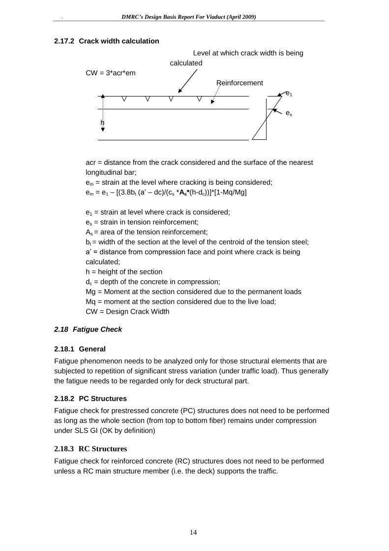
2.17.2 Crack width calculation
Level at which crack width is being
calculated
CW = 3*acr*em
Reinforcement
e1
es
h
acr = distance from the crack considered and the surface of the nearest
longitudinal bar;
em = strain at the level where cracking is being considered;
em = e1 – [(3.8bt (a‟ – dc)/(cs *As*(h-dc))]*[1-Mq/Mg]
e1 = strain at level where crack is considered;
es = strain in tension reinforcement;
As = area of the tension reinforcement;
bt = width of the section at the level of the centroid of the tension steel;
a‟ = distance from compression face and point where crack is being
calculated;
h = height of the section
dc = depth of the concrete in compression;
Mg = Moment at the section considered due to the permanent loads
Mq = moment at the section considered due to the live load;
CW = Design Crack Width
2.18 Fatigue Check
2.18.1 General
Fatigue phenomenon needs to be analyzed only for those structural elements that are
subjected to repetition of significant stress variation (under traffic load). Thus generally
the fatigue needs to be regarded only for deck structural part.
2.18.2 PC Structures
Fatigue check for prestressed concrete (PC) structures does not need to be performed
as long as the whole section (from top to bottom fiber) remains under compression
under SLS GI (OK by definition)
2.18.3 RC Structures
Fatigue check for reinforced concrete (RC) structures does not need to be performed
unless a RC main structure member (i.e. the deck) supports the traffic.

DMRC’s Design Basis Report For Viaduct (April 2009)
15
2.18.4 Steel Structures
Fatigue check is needed for steel or steel/concrete composite structures if any. Specific
Fatigue Rules as per BS: 5400-Part-10 may be followed.
Requirements of the IRS-CBC, § 13.4 shall be followed for reinforcement bar welding.
Lap welding & welding in part of deck slab subjected to concentrated loads shall not be
allowed.
2.19 Durability
Following specifications are intended to meet the durability requirements:
- Complete and adequate drainage;
- Sufficient concrete cover;
- Limiting crack width
- Appropriate concrete mixture design and good pouring, acceptable permeability
and surface finishing (IRS-CBC § 5.4)
2.20 Foundations Capacity
2.20.1 Design Assumptions for Pile Foundation
The pile cap/piles system supported by horizontal and vertical soil spring reactions is
idealized as a space frame (refer to § “Foundation stiffness” for stiffness of soil spring).
The forces applied by the pier are transferred to the bottom of the pile cap for this
purpose.
For piles and pile caps, the following load combinations shall be considered which is
part of the IRS CBC 1997, Table 12: Combinations I, II and IV.
The various specific assumptions made for the pile and pile cap design are as follows:
a) 1.50m diameter bored cast-in-situ vertical piles have been contemplated for the
foundation of piers.
b) The vertical capacity of the pile shall be based on static formula given in IS: 2911
(Part-1/Section-2). For pile carrying capacity, the SLS check only will be considered
and no reference will be made to ULS combinations. The lateral load capacity of pile
shall be evaluated by using empirical formulae given in IS:2911 ( Part-1/ section-2)
by limiting the lateral deflection of 5mm at its tip considering it as fixed headed pile
under normal conditions. The capacity so evaluated will be used purely for the
purpose of arriving at the upper bound of lateral load capacity. This deflection
limitation will not be applicable in load combinations with seismic conditions for
which the resulting stresses and capacity of the section would be the governing
criterion. The permissible increase in pile capacity for seismic load combinations
would be taken as 33.33% as per DMRC stipulations.
c) The following limiting values shall not be exceeded for computation of safe load:

DMRC’s Design Basis Report For Viaduct (April 2009)
16
(i) Results of sub-surface investigation will be used for adopting the `value
of angle of internal friction and cohesion of soil, c.
(ii) Angle of wall friction shall be taken as equal to deg.
(iii) Co-efficient of earth pressure “K” shall be taken as 1.0 generally for the
type of soil likely to be encountered.
(iv) Maximum overburden pressure at bottom of pile for calculation of shaft
resistance and end bearing resistance shall be limited to 15 times the
diameter of the pile. The maximum depth shall be considered from the
existing ground level.
(v) The entire overburden shall be assumed fully submerged for the purpose
of calculation of safe load.
(vi) Factor of safety to arrive at working load = 2.5.
(vii) Bulk density corresponding to 100% saturation shall be calculated and
used for working out submerged density of soil.
d) Initial load tests (not on working pile) shall be conducted first for determination of
safe vertical and lateral loads. The safe load shall be taken as least of (a) load
arrived at from the initial load test and (b) the calculated safe load based on static
formula. Initial test shall be conducted for a load of 2.5 times the safe vertical load
based on static formula.
e) Soil stiffness for lateral loads shall be taken from IS: 2911 (Part I/Section 2 Appendix
C). Unconfined compressive strength shall be calculated from results from
Geotechnical Investigation Report. Cohesion as calculated using unconsolidated
undrained test with required modification of angle of internal friction will be used for
working out unconfined compression strength.
f) Available geotechnical reports conclude in non liquefaction potential of the soil.
There is no historic recording of the phenomenon in the region. Despite this, the
liquefaction potential issue will be studied with the latest codal guidelines.
Liquefaction of soil will be considered for the upper strata for loose and poorly
graded sand whose SPT values is less than 15 at 5m from ground level and 25 at
10m from ground level (in accordance with IS:1893). In such condition, seismic will
be also applied on pile cap and portal action of the pile group will be considered.
When D(50) is less than 0.15mm, the SPT value to be considered for this purpose
shall be assumed as (N measured + 7.5). Due cognizance would be given to the
recommendations of the geo-technical consultants.
g) The working load on pile for vertical and horizontal loads shall be checked by
conducting routine tests during construction.
h) Spacing between the piles shall generally be not be less than 3 times the diameter
of pile in soil and 2.5 times the diameter when founded on rock.
i) Computation of bending moments along the pile length due to forces applied at the
pile cap level shall be based on a space frame model with actual stiffness of piles
restrained by springs simulating the soil stiffness. In case upper strata of soil will

DMRC’s Design Basis Report For Viaduct (April 2009)
17
have liquefaction potential, modifications in the soil springs will be introduced in the
idealization.
j) Pile cap shall be designed based on truss analogy for pile group having piles upto 5
in numbers. For other pile groups, bending theory using the space frame model
indicated above shall be employed for pile cap design. No support from soil below
pile cap shall be considered.
k) The top of pile cap shall be kept about 500mm below the existing ground level and
weight of the earth cover will be applied on top of pile cap when unfavorable. The
earth cover on pile cap for any favorable effect (stability, soil horizontal capacity.) will
be neglected
l) Pile & pile cap foundations shall be of M30.
m) The structural design of the pile and pile cap shall be checked in SLS and ULS
conditions. IRS CBC 1997 cl 15.6 shall be used for the piles. However, for crack
control in piles, cl 15.6.7 will be modified to the extent that actual axial load will be
considered to act simultaneously. For the pile cap reference will be made to cl. 15.4
and cl 15.8.3.
n) For pile carrying capacity, check shall be performed without any factorization of
loads.
2.21 Bearing System and its Design Methodology
2.21.1 Bearing System
Considering the span configuration and safety aspects of the structural system(in
normal and seismic condition), it is proposed to adopt elastomeric bearing placed
underneath box girder for transfer of vertical forces and shear key (protruding above the
pier head) for transfer of in-plane forces.
In such case, all horizontal longitudinal loads (traction / braking loads and longitudinal
seismic loads) are taken by restraining device which is a combination of horizontal tie-
bars connecting the deck with the shear key. Such arrangement of tie the superstructure
will be only done at one end of span while allowing unrestrained longitudinal movement
at the other end of the span by adequate sliding surfaces in contact with the deck.
The shear key at both end of span would also take the transverse loads (transverse
seismic, centrifugal, wind…). The shear key would anyway be also designed at each
pier head to prevent any large movements of deck due to unexpectedly larger seismic
loading (in both directions).
Concrete shear-key shall be adopted for this project.
2.21.2 Replaceability of Bearings
While finalizing the proposed bearing system, it will be kept in mind that accessibility
and replacement of each part of bearing are of paramount importance as the design life
of bearings is shorter than that of the structure. Keeping in view the above cited criteria,
all the bearings and pier caps will be detailed for replacement in the future.

DMRC’s Design Basis Report For Viaduct (April 2009)
18
2.21.3 Design Of Pot Bearings
All the pot bearings, if any, will be designed as per IRC: 83 Part-III. It is highlighted that
seismic forces used will correspond to forces as arrived from interim specification of
IRC: 6-2000.
2.22 Uplift
If found necessary, a hold-down device connecting the deck and the pier head would be
placed in order to prevent the deck from overturning. The hold-down device may be
integrated in the pot – bearing system or be a separate system constituted of bars
embedded in pier-cap and the viaduct with appropriate details permitting
translation/rotation. Other systems can also be foreseen.
Due to the lack of appropriate guidelines in Indian codes, the design criteria for hold-
down device (upward force limit requiring hold-down device, design formulas,..) will be
taken from the latest international practice ( AASHTO, MOTC codes ).
2.24 Pier Cap
Pier cap shall be designed as corbels if shear span to effective depth ration is less than
1. In other case, it shall be designed as flexural member.
2.25 Drainage of Deck / Solid Pier
2.25.1 Solid pier
The drain pipe of MS/GI with water collecting box at top with cover made up of mesh/jail
of MS/GI will be located within the solid pier to avoid aesthetics problems.
2.25.2 Deck
The top of soffit slab will be profiled so as collect the run-off water at two points by
providing a cross slope of 2.5%. Two nos of drainage pipes at each end of box girder
will be provided to collect the run-off and the same will be accommodated in the end
diaphragm in the form of Y-shape. Disposal of run-off water is affected by a runner pipe
inside the diaphragm provided at both end of girder and connected to down takes
embedded in the pier.
Design Basis Report For Viaduct
19
3. STRUCTURAL SYSTEMS
The work of whole stretch can be broadly classified into two parts namely, Viaduct & Ramp.
3.1 Structural System of Viaduct
3.1.1 Superstructure
The superstructure of a large part of the viaduct comprises of simply supported spans. However at major crossing / over or along existing bridge, special / steel girder – concrete deck composite unit will be provided.
Normally the super structure will be accommodating the two tracks situated at 4.1m c/c.
If the contractor opt the superstructure as box girder then the clear height inside the box girder to be minimum 1.0 m to facilitate inspection.
3.1.2 Substructure
The viaduct superstructure is supported on single cast-in-place RC pier.
The shape of the pier follows the flow of forces. For the standard spans, the pier gradually widens at the top to support the bearing under the box webs.
Cantilever piers will be designed for specific eccentricities & sizes will be confirmed thereon.
To prevent the direct collision of vehicle to pier, a Jersey shaped crash barrier of 1.0m height above existing road level shall be provided all around the pier with a gap of 25mm between the crash barrier and outer face of pier. The shape of upper part of pier has been so dimensioned that a required clearance of 5.5m is always available on roadside beyond vertical plane drawn on outer face of crash barrier. In such a situation, the minimum height of rail above the existing road is 9.5m.
The longitudinal center-to-center spacing of bearings over a pier would be about 1.7m. The space between the elastomeric bearings will be utilized for placing the lifting jack required for the replacement of elastomeric bearing. An outward slope of 1:200 will be provided at pier top for the drainage due to spilling of rainwater, if any.
3.1.3 Foundations
The entire stretch comprises of soil will be supported on suitable dia bored cast-in-situ vertical piles (viaduct). For typical piers, a pile group of 4 is foreseen.
In Rocky strata, if any, either open foundations or pile foundations (with toe socketted in rock) will be adopted depending on depth of rock from ground level. The same will be finalised on a case-by-case basis.
Initial pile load tests at several locations will be conducted. The intended methodology and equipment for pile installation will be employed while carrying out the initial pile load tests.
3.1.4 Parapets
Parapets shall be designed for footpath load & OHE mast loads as per the codal provisions of IS 456: 2000.
Design Basis Report For Viaduct
20
4. LIST OF DESIGN CODES AND STANDARDS
The following codes will be used in various stages of works (non-exhaustive list):
4.1 IRS Codes
IRS Substructure & Foundation Code 1985 (Include. CS 1 To CS 8) IRS Bridge Rules- 1986 (Include. CS 1 To 22) IRS Concrete Bridge Code 1997 (Include. CS 1 To CS 3)
4.2 IRC Codes
IRC: 5:1985 Standard Specification & Code Of Practice For Road Bridges-General Features Of Designs (Sixth Revision)
IRC-6-1966 Standard Specification & Code Of Practice For Road Bridges- Loads And Stresses (Third Revision)
IRC: 18-2000 Design Criteria For Prestressed Concrete Road Bridges (Post Tensioned Concrete) (3rd Revision)
IRC: 21-2000 Standard Specification & Code Of Practice For Road Bridges --Cement Concrete (Plain & Reinf.) (2nd Revision)
IRC: 78-1983 Standard Specifications & Code Of Practice For Road Bridges--Section Foundations & Sub-Structure. (1st Revision)
IRC: 83-1999: Standard Specifications & Code Of Practice For Road Bridges, Part-I Metallic Bearings
IRC: 83-1987: Standard Specifications & Code Of Practice For Road Bridges, Part-II
Elastomeric Bearings IRC: 83-1987: Standard Specifications & Code Of Practice For Road Bridges, Part-III
Pot, Pot-Cum-PTFE, Pin And Metallic Guide Bearings IRC-Sp-33-1989:Guidelines On Supplemental Measures For Design, Detailing &
Durability Of Important Bridge Structures (only Clause No- 1,2,3.1, 4.3.7, 4.3.8 & 4.3.9 are applicable)
4.3 IS Codes
IS: 269-1976 Specs for Ordinary and Low Heat Portland cement
IS: 383-1970 Specs for coarse and fine aggregate from natural sources for concrete
IS: 432-1982 Specs for Mild Steel & medium tensile steel bars (Part 1) IS: 455-1976 Specifications for Portland Slag Cement
IS: 456-2000 Code of Practice for Plain and Reinforced Concrete - based essentially on CP-110
IS: 800-1984 Code of Practice for General construction in steel IS: 875-1987 Code of Practice for Design Loads Parts 1,2,3,4 & 5 (other than
Earthquake) for Building and structures IS: 1080-1985 Design and Construction of shallow foundations in soils (Other than
Raft, Ring & Shell) IS: 1343-1980 Code of Practice for Prestressed Concrete – based essentially on CP-
110 IS: 1364-1992 Hexagon Head Bolts, screws & nuts of product grades A & B Part 1.
(Part 1) Hexagon Head Bolts (size range M1.6 to M64) IS: 1489 (Part 1) Specifications for Portland Pozzolana Cement (Flyash based) IS: 1786-1985 Specs. for High Strength Deformed steel bars and wires for concrete
reinforcement IS: 1893-1984 Criteria for Earthquake Resistant Design of structures
Design Basis Report For Viaduct
21
IS: 1904-1986 Design and Construction of Foundation in soils: General Requirements IS: 1905-1987 Code of Practice for Structural Use of Un-reinforced Masonry IS: 2062-1984 Specifications for Weldable structural steel IS: 2502-1963 Code of Practice for Bending and Fixing of Bars for Concrete
Reinforcement IS: 2911 Code of Practice for Design & Constr. of Pile Foundations Part 1 (Part 1/Sec 2) Concrete Piles. Section 2. Bored Cast-in-situ Piles IS: 2911 Code of Practice for Design & Constr. of Pile Foundations Part 4 Load test on Piles IS: 2950-1981 Designs and Construction of Raft Foundations IS: 4326-1993 Code of Practice for Earthquake Resistant Design and Construction of
Buildings IS: 4923-1997 Hollow steel sections for structural use -specification IS: 2062-1999 Steel for General Structural Purposes-specifications IS: 8009-1976 Calculation of settlement of shallow foundations IS: 8112-1989 Specification for 43 Grade Ordinary Portland cement IS: 8500-1991 Structural Steel –Micro alloyed (Medium and high strength qualities) IS: 9103-1999 Specifications for Admixtures for Concrete IS: 12070-1987 Code of Practice for Design and Construction of Shallow Foundations
on Rocks IS: 12269-1987 Specifications for 53 Grade Ordinary Portland cement IS: 13920-1993 Ductile Detailing of Reinforced Concrete Structures subjected to
Seismic Forces IS: 14268-1995 Uncoated Stress Relived Low relaxation Seven-ply Strands for
Prestressed Concrete IS: 14593-1998 Design And Construction Of Bored Cast-In-Situ Piles Founded On
Rocks- Guidelines
4.3.1 BS Codes
BS: 4447-1983 Specifications for the Performance of Prestressing Anchorages for Post-Tensioned Construction
BS: 4486 Specifications for High Tensile Steel bars used for Prestressing BS: 5400 Code Of Practice For Design Of Concrete BridgesPart-4-1990 BS: 5400 Code Of Practice For Fatigue Part-10-1990 BS: 8006 Code Of Practice For Strengthened Reinforced soils and other fills-1995 BS: 8007-1987 Design of Concrete Structures for Retaining Aqueous Liquids
4.4 Others
FIP Recommendations for the Acceptance of Post-Tensioning Systems
MOST Specifications for Road and Bridge Works – 1994
4.5 Miscellaneous
Any other codes & special publications as required and as mentioned in this report.