Embed Size (px)
Citation preview

DJP Sustainability Project
Communication Network Upgrade
Number: HO/1291/10/07
Page 1 of 31 SOW (Scope of Works)
DJP Sustainability Project
Design, supply, installation and commissioning of
additional DWDM and other Communication
Systems for the DJP and DWP Pipeline Networks.
Scope of Works (SOW)
TPL Review and Approval:
Compiled by: Reviewed by: Approved by:
Name: Henk Botes S. E. Ndlovu A Parson
Designate Network Engineer Specialist MC&I Manager
Date:
Signature:

DJP Sustainability Project
Communication Network Upgrade
Number: HO/1291/10/07
Page 2 of 31 SOW (Scope of Works)
SCOPE OF WORK (SOW)
Design, supply, installation and commissioning of
additional DWDM and other Communication
Systems for the DJP and DWP Pipeline Networks.
1.0 IDENTIFICATION OF THE PARTIES:
For the purpose of this document the following terms shall have the following meanings:
Owner shall mean Transnet Pipelines (TPL)
Employer or Client shall mean Transnet Pipelines (TPL).
Contractor shall mean the Successful Tenderer to be appointed by the Employer.
Supplier means a Subcontractor of, or supplier to the Contractor.
Contract shall mean a Legal Document mutually agreed between the Client and Contractor,
performing the required works to specifications.
Subcontractor means entity or person(s) not contracting with or employed directly by the Owner, but contracting with or employed by the Contractor or another Subcontractor,
Project Manager means the person appointed by the Employer who will attend to a wide range of duties as required by the contract.
Project Engineer means the person appointed by the Employer who will support the Project Manager performing a wide range of duties as required by the contract.
Supervisor means the person appointed by the Employer who will support the Project Manager and Project Engineer performing a wide range of duties as required by the contract.
Safety Officer shall mean the person appointed by the Employer to perform Safety
Inspections at all sites as stipulated by the contract.
Macro Design shall mean High Level Design (HLD).
Micro Design shall mean Low Level Design (LLD).

DJP Sustainability Project
Communication Network Upgrade
Number: HO/1291/10/07
Page 3 of 31 SOW (Scope of Works)
2.0 Abbreviations and definitions:
Abbreviation Description
AC Alternating current
AFC Approved for Construction
AFD Approved for Design
AFP Approved for Purchase
AIA Authorised Inspection Authority
ANSI American National Standard Institute
APC Angle Polished Connector
API American Petroleum Institute
ASME American Society of Mechanical Engineers
ASTM American Society for Testing Materials
ATN Access Transmission Network
BEP Basic Engineering Package
BOM Bill of Materials
CCC Compressor Control Cooperation
CCNA Cisco Certified Network Associate
CCTV Closed Circuit Television
CD Compact Disc
COID Compensation of Injuries and Diseases Act
CP Cathodic Protection
CWP Construction Work Package
DB Distribution Board
DC Direct Current
DCS Distributed Control System / the DCS provide the requisite process control
DJP Durban to Johannesburg Pipeline
DTE Data Terminal Equipment
DWDM Dense Wavelength Division Multiplex
E-212 The Contractors drawing and documentation requirements form
EC Electrical Completion
ECC Engineering and Construction Contract
EOJ End of Job
EPC Engineering, Procurement and Construction
EPCM Engineering, Procurement and Construction Management
ESD Emergency Shutdown System / the ESD implements the required 'critical' trips and interlocks
EW Early Warning
FAT Factory Acceptance Testing
FEA Finite Element Analysis
FFW Field Fit-up Weld
FMEA Failure Mode and Effect Analysis
FOB Free on Board
FOC Fibre Optic Cable
FTA Field Terminal Assembly
FW Field Weld
GA General Arrangement
GRP Glass Reinforced Plastic
Hardcopy Copy on paper
HAZOP Hazard and Operability Study

DJP Sustainability Project
Communication Network Upgrade
Number: HO/1291/10/07
Page 4 of 31 SOW (Scope of Works)
Abbreviation Description
HP High Pressure
HV High Voltage
HVAC Heating Ventilation and Air-Conditioning
IBL Inside Battery Limit
IC Instrumentation Completion
ICT Information Communication Technology
ICASA Independent Communications Authority of South Africa
IEC International Electro-Technical Commission
IMCC Intermediate Master Control Centre
I.R. Industrial Relations comprising all employment and labour policies, practices and procedures of the
Contractor and its sub-contractors pertaining to the Project
I.R.M Industrial Relations Manager appointed by the Employer to co-ordinate I.R. policies, practices and
procedures of the Contractor and its sub-contractors pertaining to the Project.
IS Intrinsically Safe
ISA Instrument Society of America
ISO International Standards Organisation
Iso Isometric Drawing
ITB Invitation to Bid
ITC Indicated Total Cost
LLD Low Level Design
LP Low Pressure
LV Low Voltage
MAWP Maximum Allowable Working Pressure
MBV Motorized Block Valve
MC Mechanical Completion
MCB Mini Circuit Breaker
MCC Motor Control Centre
MCP Motor Control Panel (Excitation panel)
MDMT Minimum Design Metal Temperature
MFD Mechanical Flow Diagram
MMI Man Machine Interface
MP Medium Pressure
MT Magnetic Particle Testing
MTTF Mean Time to Failure
MTTR Mean Time to Repair
MV Medium Voltage
MVA Mega Volt Amps
MW Megawatt
NCR Non Conformance Report
NDE Non-Destructive Examination
NDT Non-Destructive Testing
NEC3 New Engineering Contract
NFPA National Fire Protection Association
NMPP New Multi-Product Pipeline
NOC National Operation Centre
NOSA National Occupational Safety Association
NPSH Net Positive Suction Head
OBL Outside Battery Limit
ODF Optical Distribution Frame
OEM Original Equipment Manufacturer

DJP Sustainability Project
Communication Network Upgrade
Number: HO/1291/10/07
Page 5 of 31 SOW (Scope of Works)
Abbreviation Description
OHS ACT Occupational Health and Safety Act, Act Number 85 of 1993 as amended
ONS Optical Network System
OPC Optical Polish Conector
OTDR Optical Time Domain Reflectometer
OTS Operator Training Simulator
PAS Plant Automation System
P&G Preliminary and General
PC Practical Completion
PCN Process Control Network
PDA Potential Deviation Analysis
PDF Portable Document Format
PDU Power Distribution Unit
PEP Project Execution Plan
PFD Process Flow Diagram
PID Process and Instrument Diagram
PLC Programmable Logic Controller
ppm Parts Per Million
PQR Procedure Qualification Record
PSV Pressure Safety Valve
PT Liquid Penetrant Testing
PTP Production Test Plate
PVP Potential Variation From Plan
QA Quality Assurance
QC Quality Control
QCP Quality Control Plan
QMS Quality Management System (of the Employer)
RAM Reliability, Availability and Maintainability
RFC Ready for Commissioning
RFO Ready for Operation
SANS South African National Standards
SAT Site Acceptance Test
SCADA Supervisory Control and Data Acquisition
SPIR Spare Parts and Interchange ability Record
STM1 Synchronous Transport Module level-1
TFR Transnet Freight Rail
tpa Tons per annum / metric, 1000kg
TPL Transnet Pipelines
TSV Temperature Safety Valve
UDS User Design Specification
UPS Uninterruptible Power Supply
UV’s Utility vehicles
V Volts
VAC Volts Alternating Current
VIP’s Value Improvement Practices
VSD Variable Speed Drive

DJP Sustainability Project
Communication Network Upgrade
Number: HO/1291/10/07
Page 6 of 31 SOW (Scope of Works)
3.0 Basic Scope of Works:
3.1 Background (Overview):
3.1.1 Transnet Pipelines, a division of Transnet Ltd. currently operates over 3,000 km of
pipelines in the Republic of South Africa. TPL clients include BP, Chevron, Engen, Sasol
Oil, Sasol Gas, Shell and Total. Transnet Pipelines’ primary business is the provision of
infrastructure (pipelines, pumps stations, storage tanks etc.) for transporting of petroleum
products from the various manufacturing facilities to the South African market place.
3.1.2 One of these pipelines known as the Durban to Johannesburg Pipeline (DJP) is a refined
products pipeline that runs from the east coastline city of Durban to Sasolburg
approximately 120km to the south of Johannesburg. From there it connects with the inland
products pipeline network which receives additional products from inland refineries and
delivers these products to various points around the Johannesburg area and the inland
Provinces. The primary refined products that are transported in the pipeline system are
various grades of unleaded petrol, diesel and jet fuel.
3.1.3 The current DJP is 12” in diameter and has become capacity constrained and incapable of
supplying the needs of Transnet Pipeline’s clients. A new 24” pipeline has been
constructed by Transnet and it is known as the New Multi-Products Pipeline (NMPP)
3.1.4 Delays with the implementation of the NMPP network, due to various reasons, have
necessitated the DJP sustainability project. The aim of this project is to extend the useful
life of the DJP pipeline, by improving existing infrastructure, as cost effective as possible.
Key to this project is the requirement to maintain a sound communication network. The
existing communication network, is used to transfer process and control data from various
Pump Stations to the Master Control Center (MCC). The existing Frame Relay Network
Transmission Platform has become obsolete and therefore there is a requirement to
replace and upgrade the existing Process Control Network (PCN). The PCN must
therefore be engineered, installed and commissioned in accordance with internationally
accepted standards and procedures, as well as conforming to South African regulations.
The newly engineered solution is to be integrated into the existing DWDM, Dark Fibre and
microwave PCN equipment
3.2 General description of the works:
3.2.1 The existing communication network is making use of Neotel’s Frame Relay Network. The
Process Control, Voice and data are all routed via this Transmission platform. A variety of
Copper, Fibre and Radio (RF) links are used to establish Layer 1 connectivity.
3.2.2 The goal of this project is to replace the “older” type of Transmission platform with DWDM
and SDH network connections, either via Fibre or High Speed Radio connectivity were
applicable. The Ethernet via SDH connections required by TPL are to be supplied by
Transnet Freight Rail (TFR).
3.2.2.1 The communication system installed along the NMPP line is making use of Cisco
ONS 15454 DWDM system. The successful Contractor shall therefore be Cisco
Tier-1 certified, or as a minimum be supported by a certified contractor.
3.2.2.2 Tenderers are required to submit a Macro Design for the Works and equipment
required by TPL, with their Tender submission.

DJP Sustainability Project
Communication Network Upgrade
Number: HO/1291/10/07
Page 7 of 31 SOW (Scope of Works)
3.2.2.3 The successful Tenderer appointed by the Client, now referred to as Contractor,
be responsible to submit a Micro Design (LLD) after completing site inspections,
which is to be approved by the Project Manager and Project Engineer. It is
anticipated that the site inspections be aligned during equipment procurement
and delivery time frame, expected to be within a 6 to 8 weeks window.
3.2.2.3.1 Tenderers are to take note that 3 compulsory site assessments are to be
carried out during the tendering Phase. This is to ensure Tenders align
themselves with the conditions at typical Pump Stations. The site visit
date will be stipulated in other sections of this Tender.
3.2.2.3.2 The following sites are to be visited:
3.2.2.3.2.1 Duzi pumps station.
3.2.2.3.2.2 Ladysmith and
3.2.2.3.2.3 Wilge pump station.
3.2.3 Pump Station sites planned to make use of DWDM technology are listed below:
3.2.3.1 Contractors are requested to use the site Co-ordinate information listed in
Section 4.5, for calculating Optical losses between ONS nodes. The designs are
to take into consideration that the 24 Core is an ITU G625 rated cable.
Site Name DWDM Fibre/MW access Remarks
Howick DWDM Patched Fibre. Curently have DWDM fibre access No trenching required
Access to existing PCN Fibre
Van Reenen DWDM Fibre access required.
Trenching works required
To be priced as an option.
Scope inclusion at the descresion
of the Project Engineer
Mooi River DWDM Patched Fibre. Currently have DWDM fibre access. No No trenching required
Access to existing PCN Fibre
Duzi DWDM Fibre access required Trenching works required

DJP Sustainability Project
Communication Network Upgrade
Number: HO/1291/10/07
Page 8 of 31 SOW (Scope of Works)
3.2.4 Sites that are planned to make use of SDH (Ethernet) connectivity which are to be
supplied by Transnet Freight Rail (TFR), are listed below. A combination of Radio and
Fibre connections are to be used.
Site Name Fibre/MW
access Remarks
ARS920
switches
required
To be terminated at
NSB or DRS
Bethlehem
TPL Fibre non DWDM
To be priced as an option.
Scope inclusion at the
descresion of the Project
Engineer
Yes NSB
Newcastle Fibre non DWDM Yes DRS
Hillcrest Microwave Radio Yes DRS
Ladysmith Fibre non DWDM Yes DRS
Quagga Microwave Radio Yes DRS
Magdala Microwave Radio Yes NSB
Mngeni Microwave Radio Yes DRS
Wilge Microwave Radio Yes NSB
Fort Mistake Microwave Radio Yes NSB
3.2.5 Other sites, associated with this project are:
Site Name Fibre/MW
access ARS920 switches
required
North Station Building (NSB) Gateway Cisco 7606 installed
DRS (Durban Railway Station) Gateway Cisco 7604 installed
Main Control Center (iMCC) DWDM
(existing) Prime Optical (upgrade)
3.2.6 From the listings in section 3.2.4 above, at total of 9 x pump stations are planned to be
linked via Ethernet connections relayed via SDH physical layer. Either making use of radio
or “dark” Fibre connections. TFR (Transnet Freight Rail) are currently proposing to supply
the Radio and Fibre inter-linking networks. (This activity will thus NOT form Part of the
SCOPE of WORKS).

DJP Sustainability Project
Communication Network Upgrade
Number: HO/1291/10/07
Page 9 of 31 SOW (Scope of Works)
3.2.7 Tenderers are requested to quote for the option (A) to add additional ports to the existing
7606 and 7604 switches located at NSB and DRS respectively. In addition also quote for
the option (B) to replace these switches with later versions such as the Cisco ASR9000
series.
3.2.8 Tenderers are also requested to quote for the Supply and installation of Cisco ASR920
switches at each site listed in section 3.2.4, fitted with Ethernet trunk ports. The Client
requests that option (C) be included in the tender response, allowing the ASR920 to be
fitted with a STM-1 interface. These units are required to replace outdated Cisco 7201
gateways, currently in-use.
3.3 High Level works information summary (DWDM sites):
3.3.1 The Contractor is thus responsible to supply, install and commission the following: This is
a high level summary of the works to be completed by the Contractor. These points are
applicable to the sites listed in section 3.2.3.
3.3.1.1 The Contractor is advised that the Client shall free issue the following items
required at DWDM sites. These items are:
3.3.1.1.1 4 x 19” equipment cabinets.
3.3.1.1.2 Orange Ball Markers to be placed above each of the required manholes
at Duzi and Van Reenen.
3.3.1.1.3 Black HDPE ducts with yellow markings require at Duzi and Van Reenen
sites.
3.3.1.1.4 Fibre Optical Cable (FOC) 24 core SM, for connectivity at Duzi and Van
Reenen.
3.3.1.1.5 The Contractor to allow for delivery of these items listed above to site as
stipulated. These items are available from Transnet Pipelines Technical
Workshop in Alrode, Alberton, Gauteng Province.
3.3.1.2 Supply and installation of Eaton (Transnet approved) 5 KVA UPS’s in a 1+1
configuration for the 4 x DWDM sites listed.
3.3.1.3 It must be noted by the Contractor that Howick and Mooi River Pump Stations
are already equipped with 2 x ODF’s each. These are marked as X20 and X21
for the A and B sides respectively. Currently optical patch cords are used to
establish DWDM connectivity between nodes.
3.3.1.4 Supply and install UPS support brackets for each UPS.
3.3.1.5 The installation of free issued 19” equipment cabinets at the required sites.
3.3.1.6 Power and Earthing requirements for the equipment cabinet(s) are to be provided
in accordance with TPL specifications as listed in section 10.0
3.3.1.7 Supply and install AC mains cable between the LV bucket and the 19” rack-
mounted AC distribution unit, equipped with isolation and circuit breakers for the
UPS and ONS supply inputs.
3.3.1.7.1 Approx. 35m x Power cable per Pump Station are to be supplied and
installed. The cable must be of type: armed, 10mm2, fire resistant and
terminated both ends using cable glands.
3.3.1.7.2 Supply and install approx. 30m cable support tray between the LV panel
and 19” equipment cabinet.

DJP Sustainability Project
Communication Network Upgrade
Number: HO/1291/10/07
Page 10 of 31 SOW (Scope of Works)
3.3.1.7.3 Supply and install 32 Amp circuit breaker, in accordance to TPL
specifications, inside the LV bucket at each Pump Station.
3.3.1.7.4 2 x Red coloured Labels marked as “PCN Communication” be supplied
and fitted to the LV bucket at each site. One label to be fitted inside the
panel and the other on the LV Bucket door.
3.3.1.7.5 The 19” rack mounted AC distribution units are to be equipped with 1 x
60 Amp isolation switch at the input of the DB and 2 x 25 Amp circuit
breakers, feeding the 1+1 UPS input supply.
3.3.1.7.6 Supply a 3rd
circuit breaker rated at 15 Amps to feed the 5-way dedicated
power distribution unit. (PDU). The main function of this PDU is powering
Test equipment ONLY.
3.3.1.7.7 Supply and install approx. 35m x 70mm2 earth/grounding cable between
the Pump Station earth-bar and 19” equipment cabinet earth bar. Cable
glands and lugs are to be used, terminating the cable at the 19” cabinet
earth bar.
3.3.1.7.8 Issue Certificate of Compliance (COC) for each of the sites where
applicable.
3.3.1.8 Trenching of approx. 30m per site at Duzi and Van Reenen Pump Stations are
required, to allow for the re-routing of the NMPP 24 core blown optimized fibre
optic cable, also referred to as the Process Control Network cable (PCN).
3.3.1.9 Note: The NMPP FOC design allowed for approx. 4 km manhole spacing along
the pipe line. Fibre Optic Cable excess of approx. 15m per manhole was allowed
for by the NMPP design. The Contractor is required to release 5m FOC excess
from the 2 nearest manholes reference to the Pump Stations, allowing the
installation, termination and re-routing of the 24 core FOC at Duzi and Van
Reenen sites. The Client will assist the Contractor in locating these manholes by
using available RFID detectors.

DJP Sustainability Project
Communication Network Upgrade
Number: HO/1291/10/07
Page 11 of 31 SOW (Scope of Works)
Typical layout showing the NMPP pipeline, HDPE duct and manhole location
3.3.1.10 Free issued Ball markers are to be installed approx. 300mm above each of
the manholes.
3.3.1.11 The routing of the “new” trench will clearly and accurately be recorded on
Pump Station site layout drawings. Client to provide at award of contract.
3.3.1.12 Install 2 x 35m long Free Issued HDPE ducts (40mm x 3.7mm) to house the
2 x 24 core (PCN) Fibre Optic Cables towards Duzi and Van Reenen Pump
Stations. It is estimated that 130m per site will be adequate.
3.3.1.13 The bending radius of the HDPE ducts are 2.5m. The Contractor will ensure
this limitation is not exceeded.
3.3.1.14 The Contractor shall terminate the HDPE ducts inside the Pump Station,
underneath the Communication cabinet.
3.3.1.15 Supply and installation of an approved PVC manhole and dome joints at Duzi

DJP Sustainability Project
Communication Network Upgrade
Number: HO/1291/10/07
Page 12 of 31 SOW (Scope of Works)
and Van Reenen sites. The manholes shall allow for 2 x entries at each side.
One entry shall be used for the FOC routed along the pipeline and the second for
the “spur” towards the Pump Station. The Contractor are to allow for the required
couplings and splicing kits.
3.3.1.16 Supply and install warning tape, to be placed approx. 300mm above the
HDPE ducts. The tape shall be yellow with black lettering stating the following:
3.3.1.16.1 CAUTION TRANSNET FIBRE OPTIC TELECOM CABLE TEL:
0800203843. The warning tape shall be at least 300mm wide.
3.3.1.17 The Contractor is to take care NOT to damage the 48 core Fibre Optic Cable,
known as the EPN cable, during the excavation and rehabilitation stages of the
works. Any damage to this cable shall be for the Contractors account.
3.3.1.18 Deliver and installation of free issued 24 core FOC to Duzi and Van Reenen
Pump Stations. It is estimated that approx. 2 x 65m (130m in total) FOC per site
would be adequate.
3.3.1.18.1 The Contractor is required to perform OTDR tests on the 24 core free
issued Fibre Optic Cable, proving functionality, prior of delivery to site.
3.3.1.19 Supply and install 2 x Optical Patch Panels at Duzi and Van Reenen. One to
terminate the 24 core Optic cable, A-side, and the 2nd
Optical Patch Panel for the
B-side. All Fibres are to be terminated on to the 2 x Optical Patch Panels,
marked as X20 and X21.
3.3.1.20 All supplied Optical Patch Panels are to be equipped with E2000 (APC)
connectors.
3.3.1.21 Perform and record bi-directional OTDR tests per link.
3.3.1.22 Supply, Install and commission Cisco 15454 DWDM terminal/repeater
equipment with added DCU’s for supporting 4 x 10GBit/s nodes for each of the
sites listed. It is believed that M6 ONS chassis will offer adequate space.
3.3.1.23 Contractors to allow for the option to supply and configure Transponder cards
in a 1+1 configuration at each site.
3.3.1.24 NOTE: Commissioning of these sites will require network down time
along PL-1 (24” multiproduct pipeline), and prior approval from TPL
management must be obtained.
3.3.1.25 Supply and installation of 2 x 10m bi-directional Optical Patch Cords, per site,
equipped with LC to E2000 (APC) optical connectors. These are required to

DJP Sustainability Project
Communication Network Upgrade
Number: HO/1291/10/07
Page 13 of 31 SOW (Scope of Works)
interlink the Optical Patch Panels to the ONS equipment.
3.3.1.26 All Transponder blades shall be equipped with the required SFP’s (Small
Form Protocol) as listed in section 4.3
3.3.1.27 End-to-End link performance testing to be conducted by the Contractor and
inspected by the Client.
3.4 High Level works information summary (Linked either via Radio or Fibre):
This is a high level summary of the works to be completed by the Contractor and to be inspected
and approved by the Client. These points are applicable to the sites listed in section 3.2.4 above.
3.4.1 Supply and installation of Eaton (Transnet approved) 5 KVA UPS’s in a 1+0 configuration
for the 9 sites as indicated.
3.4.2 Supply and install UPS support brackets, due to the unit’s weight.
3.4.3 The supply and installation of 19” equipment cabinets. A total of 9 x 43U equipment
cabinets are to be allowed for by the Contractor. Refer to section 6.1.1 for more details.
3.4.4 Power and Earthing towards the equipment cabinet(s) are to be provided in accordance
with TPL specifications as indicated in section 10.1.
3.4.5 Supply and install AC mains supply, including rack-mounted AC-distribution with input
isolation and circuit breakers at the UPS and Cisco supplied switches.
3.4.5.1 Approx. 35m x Power cable per Pump Station are to be supplied and installed.
The cable must be of type SWA armored, 10mm2, fire resistant and terminated
both ends using cable glands.
3.4.5.2 Supply and install 32 Amp circuit breaker inside the LV bucket at each Pump
Station.
3.4.5.3 Supply and install approx. 30m cable support tray between the LV panel and 19”
equipment cabinet.
3.4.5.4 The 19” rack mounted AC distribution units are to be equipped with 1 x 60 Amp
isolation switch at the input of the DB and 2 x 25 Amp circuit breakers, feeding
the 1+0 UPS input supply. The 2nd
25 Amp circuit breaker shall be marked as
“SPARE”.
3.4.5.5 Supply a 3rd
circuit breaker rated at 15 Amps to feed the 5-way dedicated power
distribution unit. (PDU). The main function of this PDU is powering Test
equipment and set-up Laptop(s) ONLY.
3.4.5.6 Supply and install approx. 35m x 70mm2 earth/grounding cable between the
Pump Station earth-bar and 19” equipment cabinet. Cable glands are to be used,
terminating the cable at the 19” cabinet end.

DJP Sustainability Project
Communication Network Upgrade
Number: HO/1291/10/07
Page 14 of 31 SOW (Scope of Works)
3.4.6 Supply, installation and commissioning of Cisco ASR 920 (one per site) switch as
stipulated.
3.4.7 Supply and install a support bracket for each ASR 920 switch.
3.4.8 Supply and install 1 x duel Optical patch Cord, 5m long fitted with LC-to-LC connectors
should be adequate, between the ASR 920 and the Radio or Optical Patch Panel, for each
of the 9 sites listed.
3.4.9 Allow for High speed Ethernet Interfaces connections to be used between the Cisco ASR
920’s and the Radio Indoor units, including TFR SDH communication equipment located at
NSB and DRS.
3.4.10 The Contractor will allow for a NMS (Network Monitoring System) VLAN to be created on
one of the ASR 920 ports, which is to be used to monitor Microwave Radio link
performances at MCC.
3.5 High Level works information summary (for sites listed in section 3.2.5)
This is a high level summary of the works to be completed by the Contractor and to be inspected
and approved by the Client. This section list the work required at NSB, DRS and MCC
.
3.5.1 Supply and install additional Ethernet interface blades/ports at NSB and DRS to allow for
the 9 x additional in-land sites.
3.5.2 Supply and install heavy duty Optical interconnecting Fibre patch leads between the Cisco
7606 and 7604 towards the TFR SDH equipment. Length of 30m should be adequate at
each site.
3.5.3 Configure and setup the 7606 switch at NSB and the 7604 switch at DRS to manage the
additional Ethernet interface cards.
3.5.4 Configure these switches at NSB and DRS with an additional VLAN for the NMS services
required to be monitored at MCC.
3.5.5 Configure Cisco Prime Optical at MCC for the 4 additional DWDM sites.
3.5.6 Configure the Cisco ONS Node at MCC to allow NMS monitoring.
3.5.7 The Tenderer to allow for the provision of a Windows based workstation (PC) at MCC to
be used to monitor the in-land Microwave network performances.

DJP Sustainability Project
Communication Network Upgrade
Number: HO/1291/10/07
Page 15 of 31 SOW (Scope of Works)
3.5.8 The software required by the workstation, are to be supplied and installed by TFR.
3.5.9 Update existing documentation such as the Optical and Layer-3 Low Level Designs (LLD),
for approval.
3.6 High Level works information summary (General):
The following activities listed below are applicable to ALL sites.
3.6.1 Staging of Factory Acceptance Testing (FAT’s) – to be accepted by the Employer prior to
delivery and commissioning of the systems to site, in particular the Eaton 5KVA UPS’s.
3.6.2 Equipment acceptance inspection of all units’ prior to delivery to site, by the Client, are to
be scheduled and coordinated by the Contractor.
3.6.3 Marking and labelling all cables and components in accordance to the Client’s
specifications.
3.6.4 Issuing Network and site drawings (As Built) indicated in section 6.3.3.5 of this document,
to be approved by the Client.
3.6.5 Conduct Network Ready for Use test (NRFU’s).
3.6.6 Testing LSX, NMS and LMS VLAN fail-over at NSB via Sabre (STM-16) connection, as
supplied by TFR (SDH) network.
3.6.7 Defects identified during site inspection, and commissioning will be captured against the
responsible party and is to be resolved prior to handover unless agreed upon
3.6.8 Attend final site and network inspections.
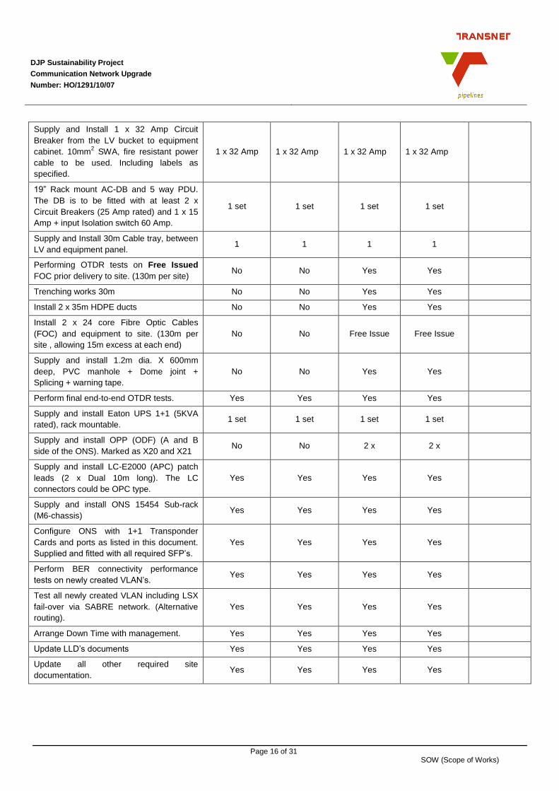
3.7 Activity summary at DWDM sites:
The Table below lists the activity and equipment to be supplied and installed per site, based on the
access technology applicable.
Activity and equipment supply +
installation works required.
Mooi River Howick Duzi Van Reenen Cost in SA
Rand (ZAR)
Delivering 19” equipment cabinet, FOC,
Power & Grounding Cables, ONS and other
installation materials to site.
Free Issue Free Issue Free Issue Free Issue
Equipment Rack installation with 35m
power cable (10mm2) and 35m
earthing/grounding (70mm2) cables.
1 x Cabinet 1 x Cabinet 1 x Cabinet 1 x Cabinet
DJP Sustainability Project
Communication Network Upgrade
Number: HO/1291/10/07
Page 16 of 31 SOW (Scope of Works)
Supply and Install 1 x 32 Amp Circuit
Breaker from the LV bucket to equipment
cabinet. 10mm2 SWA, fire resistant power
cable to be used. Including labels as
specified.
1 x 32 Amp 1 x 32 Amp 1 x 32 Amp 1 x 32 Amp
19” Rack mount AC-DB and 5 way PDU.
The DB is to be fitted with at least 2 x
Circuit Breakers (25 Amp rated) and 1 x 15
Amp + input Isolation switch 60 Amp.
1 set 1 set 1 set 1 set
Supply and Install 30m Cable tray, between
LV and equipment panel. 1 1 1 1
Performing OTDR tests on Free Issued
FOC prior delivery to site. (130m per site) No No Yes Yes
Trenching works 30m No No Yes Yes
Install 2 x 35m HDPE ducts No No Yes Yes
Install 2 x 24 core Fibre Optic Cables
(FOC) and equipment to site. (130m per
site , allowing 15m excess at each end)
No No Free Issue Free Issue
Supply and install 1.2m dia. X 600mm
deep, PVC manhole + Dome joint +
Splicing + warning tape.
No No Yes Yes
Perform final end-to-end OTDR tests. Yes Yes Yes Yes
Supply and install Eaton UPS 1+1 (5KVA
rated), rack mountable. 1 set 1 set 1 set 1 set
Supply and install OPP (ODF) (A and B
side of the ONS). Marked as X20 and X21 No No 2 x 2 x
Supply and install LC-E2000 (APC) patch
leads (2 x Dual 10m long). The LC
connectors could be OPC type.
Yes Yes Yes Yes
Supply and install ONS 15454 Sub-rack
(M6-chassis) Yes Yes Yes Yes
Configure ONS with 1+1 Transponder
Cards and ports as listed in this document.
Supplied and fitted with all required SFP’s.
Yes Yes Yes Yes
Perform BER connectivity performance
tests on newly created VLAN’s. Yes Yes Yes Yes
Test all newly created VLAN including LSX
fail-over via SABRE network. (Alternative
routing).
Yes Yes Yes Yes
Arrange Down Time with management. Yes Yes Yes Yes
Update LLD’s documents Yes Yes Yes Yes
Update all other required site
documentation. Yes Yes Yes Yes

DJP Sustainability Project
Communication Network Upgrade
Number: HO/1291/10/07
Page 17 of 31 SOW (Scope of Works)
Issue floor plans, site drawings, general
arrangement drawings for the
communication cabinet, interconnecting
arrangement, ODF arrangement, Single
Line Power arrangement required by the
project.
Yes Yes Yes Yes
Site inspection and hand over. Yes Yes Yes Yes
Attend and clear all punch items listed as
agreed. Yes Yes Yes Yes
3.8 Activity summary (Fibre and Radio sites):
Activity list including equipment
supply and installation at Pump
Stations.
Beth
lehem
TP
L
(Fib
re)
New
castle
(Fib
re)
Hillc
rest (R
ad
io)
Ladysm
ith (F
ibre
)
Quagg
a (R
ad
io)
Magd
ala
(Rad
io)
Mnge
ni (R
ad
io)
Wilg
e (R
ad
io)
Fort M
ista
ke
(Radio
)
Cost in
SA
Rand
Supply and delivery of 19” equipment cabinet
(43 U), UPS and equipment to site. 1 1 1 1 1 1 1 1 1
Equipment Rack installation with 35m Single
Phase power (10mm2.) and 35m earthing
(70mm2.) cables.
1 1 1 1 1 1 1 1 1
Supply and Install 1 x 32 Amp Circuit Breaker
from the LV bucket to equipment cabinet.
Single phase 10mm2 power cable. Armed,
Fire resistant type.
1 1 1 1 1 1 1 1 1
19” Rack mount AC-DB and 5 way PDU. The
DB is to be fitted with at least 2 x Circuit
Breakers (25 Amp rated) and 1 x 15 Amp +
input Isolation switch 60 Amp.
set set set set set set set set set
Supply and Install 30m Cable tray, between
LV and equipment panel. 1 1 1 1 1 1 1 1 1
Supply and install Eaton UPS 1+0 (5KVA
rated) with supporting bracket. 1 x 25 Amp CB
shall be used to power the UPS. The 2nd
CB
shall be marked as SPARE.
1 1 1 1 1 1 1 1 1
Supply and install LC-E2000 (APC) patch
leads (1 x Dual 10m long) between ASR920
and ODF unit at Fibre connected sites.
1 1 0 1 0 0 0 0 0
Supply and install LC-LC (OPC) patch leads
(1 x Dual 10m long) between ASR920 and
TFR radio indoor unit.
0 0 1 0 1 1 1 1 1
Supply and install Cisco ASR 920 switch with
supporting bracket.. 1 1 1 1 1 1 1 1 1
Configure ASR920 with VLAN as required. 1 1 1 1 1 1 1 1 1

DJP Sustainability Project
Communication Network Upgrade
Number: HO/1291/10/07
Page 18 of 31 SOW (Scope of Works)
Perform BER connectivity performance tests
on newly created VLAN’s. 1 1 1 1 1 1 1 1 1
Arrange Down Time with management to test
LSX connectivity. 1 1 1 1 1 1 1 1 1
Test all newly created VLAN including LSX
fail-over via SABRE network. (Alternative
routing).
Yes Yes Yes Yes Yes Yes Yes Yes Yes
Supply 20m RJ45 LAN connecting cable
(CAT5 min.) for LSX inter-linking. 1 1 1 1 1 1 1 1 1
Update LLD’s documents 1 1 1 1 1 1 1 1 1
Update site layout and other required site
documentation. 1 1 1 1 1 1 1 1 1
Site inspection and hand over. 1 1 1 1 1 1 1 1 1
Attend and clear all punch items listed and
agreed. 1 1 1 1 1 1 1 1 1
3.9 Activity summary at other sites:
Acitivity and equipment supply and installation at other Sites:
Option (A)
NS
B
DR
S
MC
C
Cost in
SA
Ran
d
Supply and install additional Ethernet ports for the 9 x In-land Pump Stations. (Min. 8 x additional ports per switch are required).
1 1 0
Configure switches and the ONS terminal at MCC for the additional VLAN’s and/or Ports.
1 1 1
Supply and install Heavy Duty Optical Patch leads (30m long) between Cisco switches and TFR SDH equipment.
4 5 0
Arrange Network Down Time with management. 1 1 1
Supply a Windows Based NMS work station for NMS monitoring. 0 0 1
Perform Network Ready For Use tests. (NRFU) Yes Yes Yes
Site inspection and network Handover. Yes Yes Yes
Acitivity and equipment supply and installation at other Sites:
Option (B)
Supply New Cisco 9000 series switches. 1 1 0

DJP Sustainability Project
Communication Network Upgrade
Number: HO/1291/10/07
Page 19 of 31 SOW (Scope of Works)
3.10 Required Spare units:
Spares to be included in Tender response are: Quantity Cost in SA Rand
Eaton 5 KVA UPS, AC 230 Volt, 50 Hz rated. Single Phase 2
Cisco ASR 920 switch Ethernet interface. (one to be kept at Durban and the second
in Johannesburg) 2
Cisco ASR 920 switch fitted with STM-1 trunk interface. Replacing 7201 units 2
Cisco High speed 8 x Port (minimum) Ethernet interface blades which are to be
used in conjunction with the Cisco 7606 and 7604 switches, located at NSB and
BRS.
2
Complete M6 Cisco ONS 15454 chassis equipped similar to the units planned to be
supplied and Installed at DWDM sites. Equipped with full set of SFP (Small Form
Protocol) connections.
1
Optical patch leads 10m each fitted with LC-to-E2000 (APC) Angle Polished
Connectors 2
Optical patch leads 10m each fitted with LC-to-LC (OPC) Optical Polished
Connectors. 2
4.0 Applicable Information:
4.1 Site names and Codes:
Station Name Number
NOC 99
MCC/ICC 98
Johannesburg NSB 96
Durban Railway Station (DRS) 97
Duzi 39
Howick 07
Mooi Rivier 54
Van Reenen 56
4.2 Process Control Network Performance criteria:
The PCN network minimum performance criteria shall meet the following parameters:
4.2.1 The network availability required to be greater than 99.4%.
4.2.2 Network response times required to be less than 400 milliseconds (ms)
4.2.3 The network equipment availability be greater than 99.9%.

DJP Sustainability Project
Communication Network Upgrade
Number: HO/1291/10/07
Page 20 of 31 SOW (Scope of Works)
4.2.4 Network response time be less than 50 milliseconds, excluding Cisco Router and Switch
alarm detection and switching latency. The end-to-end Latency shall however not exceed
150ms per link.
4.2.5 Support MTTR (mean time to respond) to be covered by a Services Level Agreement
(SLA), which is outside the scope of this Contract.
4.2.6 Support MTTR (mean time to restore), to be covered by a Services Level Agreement
(SLA), which is outside the scope of this Contract.
4.3 LAN/WAN connections required at the DWDM sites:
LAN and WAN connections required at the 4 x DWDM sites are listed below. These are in-line with
the NMPP requirement for PCS-7 platform.
Note 1: That LSX will mainly be used for the short term. However allowance are to be made for the
other “Future required” services. All applicable Ports are to be created on the ONS Transponder
Blades, that are to be supplied and configured in a 1+1 scenario, and be placed in IDLE/Blocked state
except LSX, LMS, H1 and the newly required NMS services, as indicated in the Table below.
Note 2: That a “NEW” Service are required to allow for the monitoring of Microwave Network
Management Services (NMS) from in-land sites liked via Radio transmission equipment.
Note 3: Security, Telephone and Data (ICT) services are not allowed for by this Scope of Works
document. These services are to be provided at a later stage if necessary.
Station Name
Term
inal /
Mete
ring
BU
S
Sys A
&B
CA
S
H1
ES
S
MM
S
CIS
CO
LM
S
PLM
S
PC
S7 O
S
LS
X
Inte
rne
t
DM
Z
NO
C
DM
Z
NM
S
NOC Y Y Y Y Y Y Y Y Y Y Y Y Y
202 Anton Lambede Y Y Y Y Y Y Y Y Y Y Y
Duzi Y* Y* Y* MBV Y* Y* Y
Howick Y* Y* Y* MBV Y* Y* MBV Y
Mooi River Y* Y* Y* MBV Y* Y* MBV Y
Van Reenen Y* Y* Y* MBV Y* Y* MBV Y
NSB 7604 Existing services to remain Y
DRS 7606 Existing services to remain Y
Note: Y* = Ports are to be created and Blocked until required at a later stage.
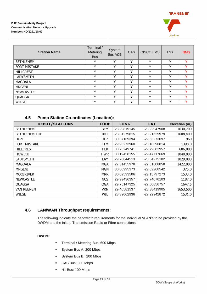
4.4 LAN/WAN requirements at In-Land sites:
The services listed below are to be created on the ASR920 to be installed at the sites as listed in the
table below. Ports to support Terminal Bus, System Bus A, System Bus B and CAS can be placed in
IDLE mode, until required.
DJP Sustainability Project
Communication Network Upgrade
Number: HO/1291/10/07
Page 21 of 31 SOW (Scope of Works)
Station Name
Terminal /
Metering
Bus
System
Bus A&B CAS CISCO LMS LSX NMS
BETHLEHEM Y Y Y Y Y Y
FORT MISTAKE Y Y Y Y Y Y
HILLCREST Y Y Y Y Y Y
LADYSMITH Y Y Y Y Y Y
MAGDALA Y Y Y Y Y Y
MNGENI Y Y Y Y Y Y
NEWCASTLE Y Y Y Y Y Y
QUAGGA Y Y Y Y Y Y
WILGE Y Y Y Y Y Y
4.5 Pump Station Co-ordinates (Location):
DEPOT/STATIONS CODE LONG LAT Elevation (m)
BETHLEHEM BEM 28.29819145 -28.22947908 1630,700
BETHLEHEM TOP BHT 28.31279815 -28.21629979 1608,400
DUZI DUZ 30.37169394 -29.53273097 960
FORT MISTAKE FTM 29.96273960 -28.18590814 1398,0
HILLCREST HLR 30.76249741 -29.79382957 686,000
HOWICK HWR 30.19458155 -29.47717669 1040,800
LADYSMITH LAY 29.78844513 -28.54275182 1029,000
MAGDALA MGA 27.31455978 -27.61600858 1422,000
MNGENI MGN 30.80995373 -29.82260542 375,0
MOOIRIVER MRR 30.02593506 -29.15797273 1533,0
NEWCASTLE NCS 29.99436357 -27.74070103 1187,0
QUAGGA QGA 29.75147325 -27.50850757 1647,5
VAN REENEN VRN 29.40581537 -28.38419905 1653,500
WILGE WIL 28.39002936 -27.22942872 1531,0
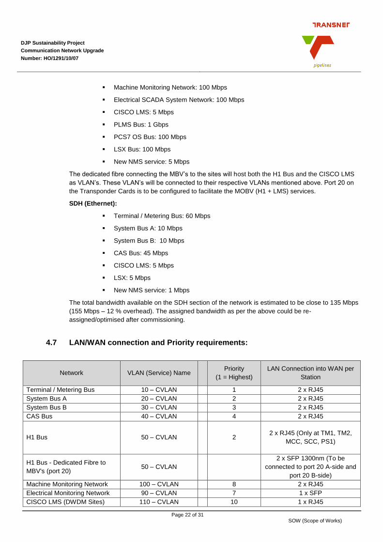
4.6 LAN/WAN Throughput requirements:
The following indicate the bandwidth requirements for the individual VLAN’s to be provided by the
DWDM and the inland Transmission Radio or Fibre connections:
DWDM:
Terminal / Metering Bus: 600 Mbps
System Bus A: 200 Mbps
System Bus B: 200 Mbps
CAS Bus: 300 Mbps
H1 Bus: 100 Mbps
DJP Sustainability Project
Communication Network Upgrade
Number: HO/1291/10/07
Page 22 of 31 SOW (Scope of Works)
Machine Monitoring Network: 100 Mbps
Electrical SCADA System Network: 100 Mbps
CISCO LMS: 5 Mbps
PLMS Bus: 1 Gbps
PCS7 OS Bus: 100 Mbps
LSX Bus: 100 Mbps
New NMS service: 5 Mbps
The dedicated fibre connecting the MBV’s to the sites will host both the H1 Bus and the CISCO LMS
as VLAN’s. These VLAN’s will be connected to their respective VLANs mentioned above. Port 20 on
the Transponder Cards is to be configured to facilitate the MOBV (H1 + LMS) services.
SDH (Ethernet):
Terminal / Metering Bus: 60 Mbps
System Bus A: 10 Mbps
System Bus B: 10 Mbps
CAS Bus: 45 Mbps
CISCO LMS: 5 Mbps
LSX: 5 Mbps
New NMS service: 1 Mbps
The total bandwidth available on the SDH section of the network is estimated to be close to 135 Mbps
(155 Mbps – 12 % overhead). The assigned bandwidth as per the above could be re-
assigned/optimised after commissioning.
4.7 LAN/WAN connection and Priority requirements:
Network VLAN (Service) Name Priority
(1 = Highest)
LAN Connection into WAN per
Station
Terminal / Metering Bus 10 – CVLAN 1 2 x RJ45
System Bus A 20 – CVLAN 2 2 x RJ45
System Bus B 30 – CVLAN 3 2 x RJ45
CAS Bus 40 – CVLAN 4 2 x RJ45
H1 Bus 50 – CVLAN 2 2 x RJ45 (Only at TM1, TM2,
MCC, SCC, PS1)
H1 Bus - Dedicated Fibre to
MBV's (port 20) 50 – CVLAN
2 x SFP 1300nm (To be
connected to port 20 A-side and
port 20 B-side)
Machine Monitoring Network 100 – CVLAN 8 2 x RJ45
Electrical Monitoring Network 90 – CVLAN 7 1 x SFP
CISCO LMS (DWDM Sites) 110 – CVLAN 10 1 x RJ45

DJP Sustainability Project
Communication Network Upgrade
Number: HO/1291/10/07
Page 23 of 31 SOW (Scope of Works)
Network VLAN (Service) Name Priority
(1 = Highest)
LAN Connection into WAN per
Station
LSX Bus 140 - CVLAN 1 1 x RJ45
NMS services for Radio sites 150- CVLAN 10 1 x RJ45
5.0 Work to be performed by the Contractor:
5.1 Design phase:
5.1.1 On acceptance of the MACRO design, to be submitted with Tender response
documentation, the successful Contractor shall be responsible to perform detailed network
design engineering of the communications network as described above. Excluding the
Microwave and “Dark” Fibre connections which are to be supplied by TFR, as previously
indicated.
5.1.2 The Contractor shall be responsible to compile detail system drawings, indicating
equipment layout, configuration and interconnectivity at each of the Nodes as listed above.
5.1.3 The Contractor shall be responsible to visit each of the listed sites to study the following:
5.1.3.1 Equipment room availability for hosting the supplied 19” equipment rack.
5.1.3.2 Study Power connectivity between the LV buckets and the equipment rack.
5.1.3.3 At Duzi and Van Reenen Pump Stations, study routing options available for
Trenching works required to house 2 x HDPE ducts.
5.1.4 The detailed design shall include proposed equipment rack layouts for Pump Station sites
and to be approved by the Project Manager and Project Engineers.
5.2 Design procedures
5.2.1 The Contractor submits all design documentation to the Project Engineers and the Project
Manager who shall be responsible for inspection, review and approval thereof.
5.2.2 The Project Engineers and the Project Manager checks and provides comments to the
Contractor’s designs, calculations and drawings. The Contractor reviews and incorporates
these comments into his design.
5.2.3 Approval of documents does not relieve the Contractor from any of his legal and
contractual liabilities and responsibilities.
5.3 Design Requirements and Reviews
5.3.1 The Contractor submits to the Project Manager all engineering documentation and
drawings as specified.
5.4 Procurement, fabrication and delivery phase
5.4.1 Inspection and Testing Requirements
5.4.1.1 The Contractor submits his procedures to the Project Manager for approval.

DJP Sustainability Project
Communication Network Upgrade
Number: HO/1291/10/07
Page 24 of 31 SOW (Scope of Works)
5.4.2 Delivery and storage requirements
5.4.2.1 Refer to Site Procedures as detailed in this Works Information document for
requirements prior to commence work on site.
5.4.3 Shipment of the Contractor supplied Equipment and Materials
5.4.3.1 The Contractor arranges all shipments of Materials and Equipment to the Site
and consigns all such shipments to the Contractor as consignee at the project
shipping address, freight fully prepaid (this includes all items, materials and
equipment free-issued) to the Contractor.
5.4.3.2 The Contractor to ensure demurrage agreements and settlements with carriers
for his shipments.
5.4.3.3 The Contractor advises the Project Manager in advance of all major shipments
of Materials and Equipment and co-ordinates with the Project Manager the
arrival, unloading and release of such. The Contractor promptly unloads its
shipments and promptly releases the carriers’ equipment.
6.0 Specific requirements to provide the Works:
The Contractor satisfies the requirements of each code, specification, attachments, drawings and all
other documents issued as an integral part of the Contract.
6.1 Supply and Installation:
All equipment shall be suitable for use in an industrial environment containing microscopic metallic
and liquid particles and dusty materials. Equipment shall operate reliably under the following ambient
conditions:
Temperature: -15 to +50 Deg. C
Humidity: 5 to 95% relative humidity
Elevation: Up to 2000 m above mean sea level
Power Supply: 230 VAC, 10A, single phase, 50 Hz
Voltage 90-110% of rated voltage
Frequency +/- 2% of rated frequency
6.1.1 Terminal and Pump Stations.
The following equipment is to be supplied and installed at DWDM and in-land Pump Stations.
6.1.1.1 Equipment Rack
6.1.1.1.1 All equipment racks shall be at least 43U high and suitable for mounting
standard 19” wide telecommunication equipment.
6.1.1.1.2 The rack shall allow for a minimum of 5 x AC (Dedicated) plugs rated at
15A each. These sockets are to be used for test and measuring
equipment.
6.1.1.1.3 Equipment racks shall be fitted with Fan trays. Cable Access to the
equipment rack shall be from the bottom, installed on computer flooring,
and the Fan tray shall therefore be located in the upper portion of the
rack.
6.1.1.1.4 Cable glands shall be used for all power and grounding cables.

DJP Sustainability Project
Communication Network Upgrade
Number: HO/1291/10/07
Page 25 of 31 SOW (Scope of Works)
6.1.1.1.5 Insulated Earth bar shall be available inside the rack, to be used for
earthing all sub-racks. The equipment rack earth bar shall be connected
to the station earth using at least 70m2 copper earth cable. Brass bolts
and nuts with serrated washers shall be used on all earth bar
connections.
6.1.1.1.6 The fibre optic ODF (Optical Distribution Frame) shall be located in the
same 19” rack. Optical patch tails shall be used to interconnect either the
Cisco ONS line drivers or the Cisco ASR920 switch to the ODF.
6.1.1.1.7 In the case of Computer Floor installations, the Equipment rack shall be
mounted on a suitable rated Galvanised Iron Frame with 4 supportive
legs by the Contractor. Each of these legs shall allow for an adjustable
nut at the bottom, to allow for proper alignment with the Computer Floor.
The Project Manager will inform the Contractor for the Computer Floor
heights, which in general is 450mm above the concrete floor.
6.1.1.2 Cisco ONS 15454 Equipment:
The Cisco ONS 15454 ETSI chassis have the following environmental
parameters.
Power consumption 1728 Watts
BTU per hour 6000 BTU
The Contractor to update this information and also provide the parameters
applicable to the ASR920 switch.
6.2 Construction management:
6.2.1 The Contractor manages it’s access to the working areas and the Site.
6.2.2 The Contractor manages it’s activities on Site to ensure that no interference takes place
between his work and that of others
6.2.3 The Contractor liaises with the Project Manager regarding utilities and telephone facilities
required for it’s site establishment
6.2.4 The Contractor liaises with the Project Manager regarding the location of waste disposal
sites and rubbish dumps.
6.2.5 The Contractor maintains and promotes labour harmony on the Site and the working
environment.
6.2.6 The Contractor immediately reports any potential labour disharmony to the Project
Manager
6.2.7 The Contractor does not recruit or employ any personnel from the Employer, sub-
contractor and others, without prior approval of the Project Manager
6.2.8 The Contractor co-ordinates with the facilities contractor in the working areas.
6.2.9 The Contractor's site supervisor is an experienced, qualified and responsible person who

DJP Sustainability Project
Communication Network Upgrade
Number: HO/1291/10/07
Page 26 of 31 SOW (Scope of Works)
is available at all times during progress of the works, and acts and represents the
Contractor, and all instructions given to him are binding as if given to the Contractor.
6.3 Fibre Optic cable Installation:
6.3.1 The Contractor shall as part of his scope supply, install and commission DHPE Ducts,
Manholes, Dome Joints and to install Free issued 24 core Blown optimised fibre optic
cables to complete the transmission links at sites stipulated. The Contractor shall comply
with Transnet Standards and procedures listed in section 10.1.
6.3.2 Commissioning and Support:
6.3.2.1 The Contractor is to check prior to commissioning and then have approved by
the Client the OTDR Fibre Test results during Commissioning of the cables.
6.3.2.2 The Contractor to provide support to the network, but is not responsible for the
monitoring, operations and maintenance of the PCN network. This SLA (Service
Level Agreement) does not form part of the scope of works. (will be addressed by
‘others’)
6.3.3 Hand-over procedures and documentation requirements.
6.3.3.1 The Client in conjunction with the Contractor shall inspect each of the sites as
listed, for proper installation standards which shall include wiring, earthing,
marking, routing and mounting standards. Approved punch lists shall be
completed per installation and added to the as built documentation.
6.3.3.2 Redundancy routing shall also be tested by the Contractor and witnessed by the
Client for functionality.
6.3.3.3 The Client shall highlight any defaults to the Contractor which are to be corrected
within the approved time frame.
6.3.3.4 The Project Manager to signoff all documents on acceptance.
6.3.3.5 The ‘As Built’ documents shall contain the following:
6.3.3.5.1 Equipment rack layouts also known as General Arrangement
6.3.3.5.2 Floor Plan layout.
6.3.3.5.3 Red Line site layout drawings, indicating the accurate routing of Fibre
Optic Cables added by the project.
6.3.3.5.4 Wiring diagrams (per site)
6.3.3.5.5 ODF arrangement
6.3.3.5.6 Wiring schedules (list of cable numbers).
6.3.3.5.7 Network Block diagrams.
6.3.3.5.8 Network interconnecting diagrams.
6.3.3.5.9 Heat load and power consumption table per site.
6.3.3.5.10 Bit Error Ratios (BER) results for all links provided.
6.3.3.5.11 OTDR results as measured per fibre.
6.3.3.5.12 Equipment schedules (list of equipment and serial numbers).
6.3.3.5.13 All COC documentation per required sites. (2 copies each)

DJP Sustainability Project
Communication Network Upgrade
Number: HO/1291/10/07
Page 27 of 31 SOW (Scope of Works)
6.3.4 Clean-up requirements
6.3.4.1 Upon completion of the works, the Contractor promptly returns unused materials
furnished by the Project Manager or the Employer and removes from the Site all
of the Contractor's equipment, material and like items, leaving the Site and the
vicinity clean, safe and ready for use.
7.0 Work, Health and Safety:
The Contactor will be responsible to appoint a Health and Safety Officer to the project, responsible to perform
necessary inspections, reports and taking corrective actions if and when required. The Client Health and
Safety appointed inspector will from time to time perform inspections, without prior notification, to verify the
Contactors code of conduct.
7.1 The Contractor and its sub-contractors who provide the Works at the Site at all times works safely and
comply strictly with all governmental, provincial, municipal and local laws, ordinances, regulations, by-
laws and acts of parliament pertaining to health or safety which are applicable to the Contractor and
its sub-contractors or to the work including without limitation the OHS Act, as amended, and
regulations there under, and the Contractor warrants that the work complies therewith.
7.2 The Contractor provides proof to the Project Manager that the Contractor and its sub-contractors
comply with the requirements of the COID Act 130 of 1993.
7.3 The Occupational Health and Safety Act No 85 of 1993 and the regulations promulgated in terms of
the Act, as amended, are the Act governing the Site. Specific attention is drawn to the requirements
of the Construction Regulations as promulgated in 2003.The Contractor and its sub-contractors
comply with all the legal requirements of the said Act whilst working on the Site. This agreement
serves to exclude the presumption in Section 37(1) of the Occupational Health and Safety Act and
serves to meet the requirements of Section 37(2) of the Act. Proof of the appointments made by the
Contractor and sub-contractors in accordance with the Act are available at the Site at all times while
the Contractor is providing the Works; for inspection by any representative of the Employer.
7.4 With regards to Section 37(2) of the OHS Act, the Contractor hereby acknowledges that it is an
Employer in its own right with duties as prescribed in the OHS Act, and the Contractor hereby ensures
that all work is performed and machinery and equipment used in accordance with the provisions of the
OHS Act. The Contractor hereby agrees to advise the Employer promptly if it is unable to comply with
the foregoing undertaking at any time for whatever reason.
7.5 The Contractor and its sub-contractor comply with the General Administrative Regulation 14 of the
OHS Act: “Notice of carrying out of construction work”. The details of the notice are delivered to the
Control Inspector, Department of Labour, in writing on official stationery (Letter head) of the
organisation and a copy is submitted to the Project Manager.
7.6 The Contractor and its sub-contractor comply with the requirements of the NOSA three (3) star
grading or equivalent accredited standards on Site until the completion date is achieved. All
temporary facilities erected by the Contractor at the Site conform to the NOSA three (3) star grading

DJP Sustainability Project
Communication Network Upgrade
Number: HO/1291/10/07
Page 28 of 31 SOW (Scope of Works)
requirements. If the Contractor needs any information on these requirements, he contacts the
Employers Environmental and Risk Departments.
7.7 The Contractor and its sub-contractor undertake that, in order to provide the Works within the
boundaries of the Site comply at all times with the instructions and requirements of the applicable
Employer codes and procedures. The Employer’s codes and procedures are available upon request.
7.8 The Contractor familiarises himself and its sub-contractor with the Employer’s codes, procedures and
assures compliance thereto by its employees and its sub-contractor employees. The Contractor
ensures that it is in possession of the latest editions of the applicable codes at all times. If any
requirements of the codes are in conflict with the requirements of the Occupational Health and Safety
Act of 1993, as amended, compliance to the said Act takes precedence.
7.9 The Contractor and its sub-contractor conduct a risk assessment performed by a competent person
before providing the Works at the Site. The risk assessment forms part of the health and safety
program applied on the Site by the Contractor. The risk assessment includes as a minimum:
7.9.1 The identification of the risks and hazards to which an individual’s health and safety may
be exposed;
7.9.2 The analysis and evaluation of the hazards identified;
7.9.3 A documented plan and safe work procedures to mitigate, reduce or control the risks
identified; and
7.9.4 A monitoring and review plan of the risks and hazards.
7.10 The Contractor and its sub-contractor ensure that a copy of the hazard identification and risk
assessment is available at the Site for inspection by an inspector. A duplicate copy is available for the
Employer, any employee, any organisation, health and safety representative or member of the health
and safety committee.
7.11 The Contractor and its sub-contractor submit and demonstrate to the Employer before providing the
Works a documented health and safety plan, based on the Employer’s health and safety specification
provided. The health and safety plan is applied from the starting date until the end of the defect
correction period. A copy of such plan is available on request from the Employer.
7.11.1 The Employer has the right to stop work whenever safety violations are observed which
could jeopardize the wellbeing of personnel and equipment. The expense of any such
work stoppage and resultant standby time are for the Contractor's account. The failure or
refusal of the Contractor to correct the observed violation may result in the termination of
the Contract, and/or the dismissal from the Site of those responsible for such failure or
refusal.
7.11.2 The Employer may inspect the Contractor’s Equipment, Plant and Materials and the
Contractor satisfies himself that his Equipment, Plant and Materials are safe to use before
commencement and during the works.
DJP Sustainability Project
Communication Network Upgrade
Number: HO/1291/10/07
Page 29 of 31 SOW (Scope of Works)
7.11.3 The Contractor undertakes to replace any Equipment, Plant and Materials which are in the
Employer’s opinion unsafe to use and the Employer may stop work in which the unsafe
item is being used. The Contractor undertakes to have hard hats, hand gloves, safety
shoes, long sleeved overalls and any other safety apparel and devices as the specific
areas or tasks require whilst working in the Working Areas.
7.12 To preserve the high safety standards, the Contractor undertakes to:
7.12.1 Successfully undergo safety induction training regarding the Employer’s safety
requirements of the specific Working Areas (the duration of the training depends on the
area and the specific requirements, but generally requires two hours or less).
7.12.2 Undergo training in the Employer’s Work Permit system (generally requires 2 hours)
7.12.3 Attend training for the entry into confined spaces when required.
7.12.4 The Contractor, its supervisor’s i.e. Persons appointed and/or responsible in terms of the
OHS Act and all its personnel are subject to, and will successfully undergo, training
regarding safety requirements of specific areas. The duration of the training depends on
the area and the specific requirements, but generally requires 2 (two) hours.
7.12.5 The Contractor with permanent site establishment within the Site has a minimum NOSA 3
star grading.
7.12.6 The Contractor provides identification badges to all its employees working either directly or
indirectly under its supervision. These badges are worn conspicuously by these employees
at all times when on the Site.
7.12.7 Smoking is not allowed in the work area(s) or outside of the designated smoking area.
7.12.8 The Contractor's personnel wears hard hats clearly marked with employee name,
company logo, safety boots, safety glasses and all other necessary and required safety
equipment and clothing.
8.0 Quality Requirements
8.1 General
8.1.1 The Contractor performs all quality related activities as specified in ISO 9001:2000 “Quality
Management Systems Requirements”, or equivalent acceptable to the Employer.
8.1.2 The Contractor provides the necessary quality management systems to ensure that the
quality of the works complies with the requirements of the Works Information.
8.1.3 The Employer reserves the right to review certified material test reports for all materials of

DJP Sustainability Project
Communication Network Upgrade
Number: HO/1291/10/07
Page 30 of 31 SOW (Scope of Works)
construction at any time during field erection. The Contractor maintains these documents
readily available for such review and submits all documents to the Employer on completion
of the works.
8.1.4 The Contractor's performance of his obligations under the Contract are not deemed
complete until the Project Manager is in receipt, on proper forms, of all Technical Data and
other documents to be submitted to the Project Manager as part of the Contractor's work.
Failure of the Contractor to comply with the Quality requirements entitles the Employer to
withhold any progress payment, or final payment, pending the Project Managers receipt of
all the above data without prejudice to any other remedy of the Employer.
8.1.5 The Contractor submits a comprehensive Project Quality Plan (PQP) specifically tailored to
the requirements of this Contract for the approval of the Employer. The Contractor will
carry out and monitor the Works in accordance with the approved Quality Plan.
9.0 Security and Site Procedures
9.1 Site security provision
9.1.1 The Contractor recognizes and accepts that the Employer considers the areas and
facilities affected by this project to be of vital concern to its operations. The Contractor
provides overall perimeter security and personnel and vehicle access for all such areas
and facilities including a security plan for the Contractor’s lay down sites and work sites.
The Employer/Project Manager may insist upon any additional security measures as may
be imposed by Government or other lawful body at any time, or deemed necessary from
time to time throughout the period the Contractor is on the Site.
9.2 Site work rules and regulations.
9.2.1 The Contractor complies with all currently applicable work rules and regulations as detailed
and stipulated by Transnet Site Security policy.
9.2.2 The Client does not permit personnel who are under the influence of drugs or alcohol to
enter the Works Area.
9.2.3 Only a valid identification document is accepted as proof of identity. (S.A Identity
Document or valid Passport)
9.3 Personal Entry Security Requirements
9.3.1 All the Contractor’s personnel receive a site access badge upon completion of all required
Site inductions.
9.4 Contractors vehicles access to Existing Sites
9.4.1 Only a limited number of the Contractor’s vehicles are allowed access to existing site and
facilities and this is determined on a need basis as motivated from time to time.
9.5 Work Permits.
9.5.1 The Contractor does not commence with any excavation without the necessary Excavation
Permits and the prior acceptance by the Employer.

DJP Sustainability Project
Communication Network Upgrade
Number: HO/1291/10/07
Page 31 of 31 SOW (Scope of Works)
10.0 Related Documents:
10.1 The following documents (latest revisions) must be studied in conjunction with the Scope of Works.
These documents list and stipulate TPL’s specifications and requirements.
10.1.1 PL727-11 Code of Practice, Cabling, Racking, Trenching & Earthing.
10.1.2 PL711-10 Specifications for equipment Cabinets to house Electronic Equipment
10.1.3 PL631-9 Specification for Low Voltage Switchgear DB’s
10.1.4 PL 100 Drawing Standards.
10.1.5 PL 101 Plant & Equipment Tag Numbering Standards.
10.1.6 PL 102 Equipment, Instrument & Electrical Symbols Standards
10.1.7 PL 103 General Drawing Standards.
10.1.8 PL 720 Specifications for UPS.
10.1.9 PL 666-1 TPL Electrical Design Criteria.
10.2 Other related Documents:
10.2.1 2684358-N-A00-QA-TR-010_Transnet Pipelines TPL Project LSX Comm document
v2.0_signed TCP_TPL_18 03 2016
10.2.2 2684358-N-A00-QA-TR-011_Transnet Pipelines TPL Project ASR 920 POC - Test
document_v2.1_signed TCP_TPL_18 03 2016
10.2.3 2684358-J-A00-CS-SP-001 (01) - Pipeline Network Design Criteria
10.3 ITU Recommendations:
All listed ITU documents are available and accessable via the WEB.
10.3.1 [ITU-T G.826] Recommendation ITU-T G.826 (2002), End-to-end error performance
parameters and objectives for international, constant bit-rate digital paths and connections.
10.3.2 [ITU-T G.694.1] Recommendation ITU-T G.694.1 (2002), Spectral grids for WDM
applications: DWDM frequency grid.
10.3.3 [ITU-T G.694.2] Recommendation ITU-T G.694.2 (2003), Spectral grids for WDM
applications: CWDM wavelength grid.
10.3.4 [ITU-T G.698.2] Recommendation ITU-T G.698.2 (2007), Amplified multichannel DWDM
applications with single channel optical interfaces
10.3.5 [ITU-T G.691] Recommendation ITU-T G.691 (2006), Optical interfaces for single channel
STM-64 and other SDH systems with optical amplifiers
*** END OF DOCUMENT ***


![VOLUME 2, SECTION 2.1: PROGRAM MANAGEMENT · 2018. 11. 6. · 2.1.1 Contractor’s Program Organization [C.3.2.2.1] ... contracting) in leadership positions . Enterprise SM Volume](https://img.pdfslide.us/doc/110x75/60e778ed06ea14064e25e16f/volume-2-section-21-program-management-2018-11-6-211-contractoras-program.jpg)