Embed Size (px)
Citation preview

Outline
• Motivation / Applications
• System architecture
• Current status
• Feature wishlist / future work

Introduction
• 7 people doing full time research specifically on unmanned systems– Project management: Halvor Bjordal, Lorns Bakstad
• Involved in other Nato STO groups– SCI-186 (finished), «Architectures for ops. with manned/unmanned
systems»– SCI-ET-004 (just starting), «Simulation and analysis of future ops. with
manned/unmanned air and ground vehicles»– Both chaired by Morten Hansbø (FFI)
• Disclaimer: Started at FFI in March this year– Background in materials science / semiconductors– Materials for high temperature / high power electronics– Solar cells

Motivation
Theoretical analysis• Modelling
• Architectures, solutions, functionality• Concepts of operation (CONOPS)• Operational activities (TTP-tactics, techniques and procedures)
•Capabilities & goals: Measures of Merit• Theoretical evaluation and validation
Field tests• Field lab• RAVEN• FACNAV• C2ISR
composite structure Top level NCV-2
«Capability»Effectively and efficiently operate unmanned aircraft
together with manned aircraft.
«Capability»Operate lawfully and ethically
(adhere to the ROE)
«Capability»Achieve Desirable Effects (kinetic
and non-kinetic)
«Capability»Cooperative Joint ISR
«Capability»Command and control
«Capability»Airspace management
«Capability»Security
«Capability»Logistics and support
«Capability»Situation awareness generation
and maintenance
«Capability»Human-machine collaboration /
support human roles
«Capability»Communications and networking
«Capability»Planning, deliberation and
prediction
«Capability»Information management, storage
and distribution
«Capability»Survive to Operate / Operate
safely
NCV-2 Capability TaxonomySCI-186 Top Level
The NCV-2 describes the capabilities which must be realized by the solutions (the systems, their functions and the composition of resources in capability configurations). These solutions are described in the NSV. The capabilities in NCV-2 express the user requirements on the solution architecture, and further specify the highest level Vision and goals that are expressed in the NCV-1 Enterprise Vision. MoM-identification take input directly from the capabilities. The MoMs are what will actually be verified/measured to ascertain whether the capabilities are realised by the architecture. MoMs are described in separate diagrams.
«CapabilitySpecialization»
class NOV-2 Core of concept
«Node»Local data exploitation
and fusion (airborne)
«Node»Sensor and limited
data exploitation
NOV-2 Operational Node Relationship Description
«Node»Time critical info use
(strike)
(With alternatives for node realization)
«Node»C2 for manned and
UAS (local and remote)
An NOV-2 node relationship description with proposed options for node realisation by capability configurations, here represented by the various platform types. The relationship "NodeRealization" from NAFv3 is used between the nodes and the capability configurations.
The important idea/message in this diagram is that both C2 and sensor data exploitation is envisioned to be performed distributively and collaboratively, with much C2 and exploitation going on locally near the tactical operation (target area).
«Needline»
C2, Status, Selected imagery«Needline»
Selected Imagery, Target Information«Needline»
Selected Imagery, target information
«Needline»
C2, status, selected imagery«Needline»
Selected partially exploited data
«Needline»
Support analysis and synthesis of concepts and solutions for manned-unmanned combined operations
Simulation• Visualization
• Increase understanding
• Evaluation• Measurements• Qualitative evaluations

Goals for the simulator
• Provide effective visualization and scientific inspiration– Both aircraft (UAS) and ground (UGS) systems
• Evaluation of concepts and solutions– both quantitative (logging) and qualitative analysis
• Support research on complex issues– From BIG (organisational, concepts) to small (tactical, technical and human issues)
• Distributed, modular and flexible– Functionality located at several locations/workstations (e.g. navigation and payload op.)– Currently uses DIS, will use HLA
• Use existing components as much as possible– Little custom development, mostly integration of existing systems
• Use NATO standards (STANAG) for communication (control + data)– Allows HW-in-the-loop with existing ground station, autopilot, platforms, etc.

Applications

Example applications
Challenges which can be studied in simulations• Environmental
– Snow cover, precipitation, cloud coverage, wind
• Topographical– Link coverage in mountainous terrain (radio shadows)
• Technical– Ground station usability, endurance, navigation,
automation/autonomous operation, usefulness of particular technical solutions prior to practical implementation
• Organizational– optimal geographical distribution of UAS, operator/platform ratio,
integration with C2-systems & CSD

Shameless plugof Norwegian nature
Radio shadow, need• higher altitude aircraft• relay aircraft
Raven B useful altitude (AGL)
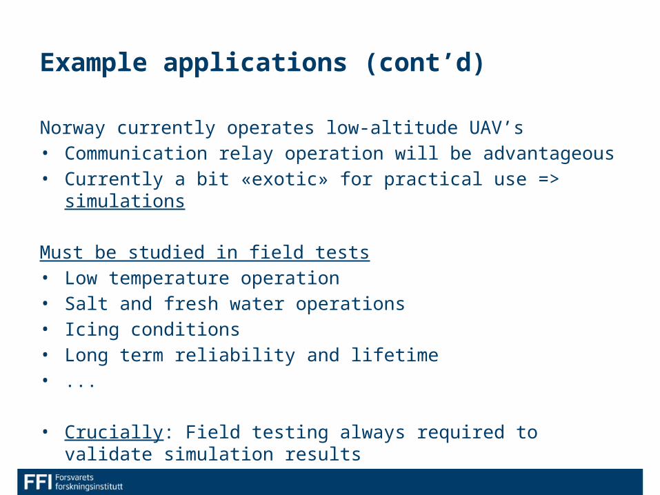
Norway currently operates low-altitude UAV’s• Communication relay operation will be advantageous• Currently a bit «exotic» for practical use => simulations
Must be studied in field tests• Low temperature operation• Salt and fresh water operations• Icing conditions• Long term reliability and lifetime• ...
• Crucially: Field testing always required to validate simulation results
Example applications (cont’d)

Simulator• Develop plugins for
– Ground control station (currently Maria, planning purchase of COTS)– Vehicle simulator (X-Plane, a serious game flight simulator)– Sensor simulator (VBS2, video transmission + sensor control)
Ground control station
Vehicle simulator Sensor simulator

UAS simulator
Ground station
Vehicle sim. Sensor sim.
STANAG 4586
Com-sim. (link quality)
Synchronization (HLA) Other sim.
PlatformsVSM
BMS / CSDCursor-on-target

UAS simulator
«Ground station»
Vehicle sim.«Sensor»
sim.
«STANAG 4586»
1:1
Synchronization (HLA) Other sim.
Platforms
BMS / CSDCursor-on-target

• Realism: Challenges with using e.g. VBS2 as image generator– Sensor has advanced features (e.g. much more advanced than Raven B)– Extremely good contrast images– High resolution (can be changed somewhat)– Noiseless sensors and radio reception => crystal clear images
– All of the above will be changed for the worse
• Need a communication simulator for generating link-issues– Long distance, loss of line-of-sight, weather, etc.– Will start with very simple simulator (link / no link), expand with time
Feature wishlist / todo-list

• Implement much better autopilot for vehicle simulator– Have successfully used hw-in-the-loop (ArduPilot) in related activity
• Fully STANAG compatible communication– Considering COTS software library (Instrument Control AB)
• Image analysis station– Already have an in-house prototype analysis station in our field lab– Will create a set up for analysis of simulated data with COTS software
• Use generated real time video in various image analysis techniques (detection, classification, scene reconstruction, ++)
• Generate simulated data for input to a coalition shared database (CSD)
Feature wishlist / todo-list (cont’d)

Raven UAV in VBS2 (640x480).
Questions?

Backup slides

Vehicle sim.Vehicle sim.Vehicle sim.
4586 (App. 1)
4609
4586 (App. 2)/CoT
4586 (App. 2) / 4609
GCSVisualization(Sensor sim)
Synchronization (HLA)
BMS(FACNAV)
CSDVehicle sim.
System architecture• Communications will follow UAV-related STANAG’s
– 4609 & 4545 for video/images, 4586 for control signals
Ground control station

Raven UAV in VBS2 (640x480).