Embed Size (px)
Citation preview
LARS BridgeTM Specification Analysis
LARS
(Load Analysis and Rating System)
Specification Analysis Manual
August 2010
Bentley Systems, Inc. Exton, PA
LARS BridgeTM Specification Analysis
2
Bentley, the "B" Bentley logo, and BridgeModeler and LARS are registered or non-
registered trademarks of Bentley Systems, Inc. or Bentley Software, Inc. All other marks
are the property of their respective owners.
If this software is acquired for or on behalf of the United States of America, its agencies
and/or instrumentalities ("U.S. Government"), it is provided with restricted rights. This
software and accompanying documentation are "commercial computer software" and
"commercial computer software documentation," respectively, pursuant to 48 C.F.R.
12.212 and 227.7202, and "restricted computer software" pursuant to 48 C.F.R. 52.227-
19(a), as applicable. Use, modification, reproduction, release, performance, display or
disclosure of this software and accompanying documentation by the U.S. Government are
subject to restrictions as set forth in this Agreement and pursuant to 48 C.F.R. 12.212,
52.227-19, 227.7202, and 1852.227-86, as applicable. Contractor/Manufacturer is
Bentley Systems, Incorporated, 685 Stockton Drive, Exton, PA 19341-0678.
Unpublished - rights reserved under the Copyright Laws of the United States and
International treaties.
© 2009, Bentley Systems, Incorporated. All Rights Reserved.
Including software, file formats, and audiovisual displays; may only be used pursuant to
applicable software license agreement; contains confidential and proprietary information
of Bentley Systems, Incorporated and/or third parties which is protected by copyright and
trade secret law and may not be provided or otherwise made available without proper
authorization.
LARS BridgeTM Specification Analysis
3
TABLE OF CONTENTS
INTRODUCTION..........................................................................................................................5
Description of LARS Analysis ......................................................................................................6
LARS Analysis Methods for Flexural Members .........................................................................7
1. STRUCTURAL STEEL AND COMPOSITE STEEL AND CONCRETE .......................14
1.1 Allowable Stress Design Method .....................................................................................20
1.1.1 Moment Analysis ......................................................................................................21
1.1.2 Moment Analysis for Hybrid Girders .......................................................................25
1.1.3 Shear Analysis ..........................................................................................................28
1.2 Load Factor Design Method ............................................................................................37
1.2.1 Moment Analysis for Compact Section, Braced Non-Compact and Unbraced
Non-Compact ...............................................................................................................41
1.2.2 Moment Analysis for Composite Compact Sections and Braced Non-Compact
Sections ........................................................................................................................49
1.2.3 Moment Analysis for Hybrid Girders ..........................................................................61
1.2.4 Shear Analysis .............................................................................................................67
1.2.5 Moment - Shear Interaction .........................................................................................71
1.2.6 Stiffener Requirements ................................................................................................74
1.2.7 Serviceability Moment Analysis ..................................................................................76
2. REINFORCED CONCRETE ...............................................................................................79
2.1 Allowable Stress Design Method .....................................................................................83
2.1.1 Moment Analysis .........................................................................................................84
2.1.2 Shear Analysis .............................................................................................................86
2.2 Load Factor Design Method ............................................................................................91
LARS BridgeTM Specification Analysis
4
2.2.1 Moment Analysis .........................................................................................................92
2.2.2 Shear Analysis ............................................................................................................100
3 . PRESTRESSED CONCRETE AND COMPOSITE PRESTRESSED CONCRETE ....105
3.1 Allowable Stress Design and Load Factor Design Methods........................................113
3.1.1 Moment Analysis .......................................................................................................114
3.1.2 Low Tendon Analysis ................................................................................................134
3.1.3 Shear Analysis ...........................................................................................................137
3.1.4 Serviceability Moment Analysis ................................................................................142
4. TIMBER ................................................................................................................................145
LARS BridgeTM Specification Analysis
5
INTRODUCTION
DESCRIPTION OF LARS ANALYSIS
LARS ANALYSIS METHODS
FOR
FLEXURAL MEMBERS
LARS BridgeTM Specification Analysis
6
Description of LARS Analysis
The basic analysis methods (i.e., section property, influence lines, and dead load and live load
analysis) of the Load Analysis Rating System (LARS) are very similar to those that have been
employed in BARS. The majority of analysis results are presented in LARS reports that have
headings and labels that fairly clearly describe the associated data. The key values that control
the evaluation of the bridge are the moment capacity and available capacity for Live Load +
Impact (LL + IMP). These results are produced by executing calculations that are defined by the
AASHTO Bridge Specifications, while using the data describing member section properties and
the moment and shear values that are applied to the section being analyzed. The calculations are
intermixed with logical tests of the intermediate results of the calculations. These logical tests
guide the analysis to the various calculations that relate to the type of member section (e.g., non-
composite, composite, compact, braced non-compact or unbraced non-compact for steel) within
a material of construction type (i.e., for steel, composite steel and concrete, reinforced concrete,
prestressed concrete, composite prestressed concrete). The following descriptions are directed
toward the clarification of the logical criteria and the calculation methods that produce the
moment capacity and the available capacity for LL + IMP for structural steel, composite steel
and concrete, reinforced concrete, prestressed concrete and composite prestressed concrete.
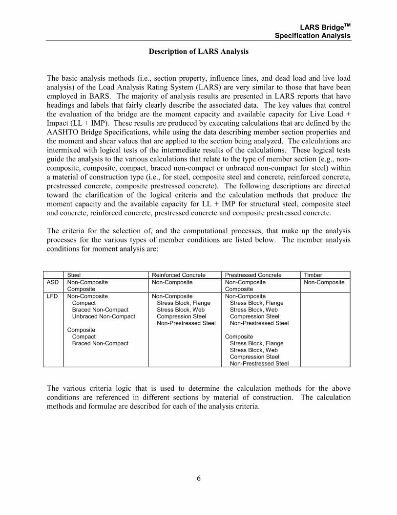
The criteria for the selection of, and the computational processes, that make up the analysis
processes for the various types of member conditions are listed below. The member analysis
conditions for moment analysis are:
Steel Reinforced Concrete Prestressed Concrete Timber
ASD Non-Composite Composite
Non-Composite Non-Composite Composite
Non-Composite
LFD Non-Composite Compact Braced Non-Compact Unbraced Non-Compact Composite Compact Braced Non-Compact
Non-Composite Stress Block, Flange Stress Block, Web Compression Steel Non-Prestressed Steel
Non-Composite Stress Block, Flange Stress Block, Web Compression Steel Non-Prestressed Steel Composite Stress Block, Flange Stress Block, Web Compression Steel Non-Prestressed Steel
The various criteria logic that is used to determine the calculation methods for the above
conditions are referenced in different sections by material of construction. The calculation
methods and formulae are described for each of the analysis criteria.
LARS BridgeTM Specification Analysis
7
LARS Analysis Methods for Flexural Members
The following is a discussion of the way in which LARS analyzes flexural members for the
various conditions of:
• ASD or LFD analysis methods
• Non-composite or composite action
• Positive or negative bending
• Analysis of top or bottom of section
• Structural steel sections resistance to local buckling and torsional buckling
• Reinforced concrete shape types with reinforcing for tension only, or tension and
compression
• Prestressed concrete shape types and analysis methods
The discussion utilizes a series of tables to depict the manner in which LARS performs its
analysis for the various interrelationships between each of these conditions. These tables address
only the general form of the analysis. Later sections of this document will describe the detailed
criteria to select the specific equations, and the formulae used in accordance with the Bridge
Specifications.
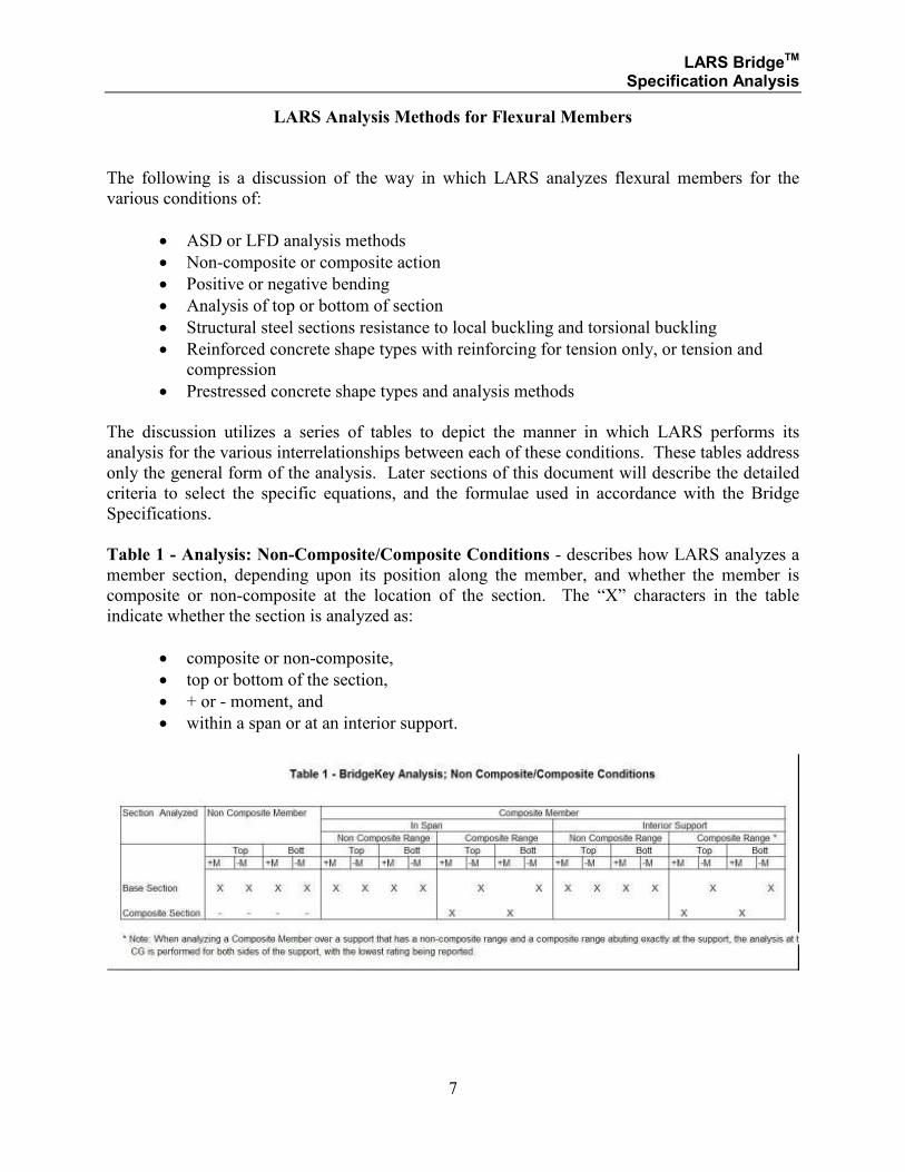
Table 1 - Analysis: Non-Composite/Composite Conditions - describes how LARS analyzes a
member section, depending upon its position along the member, and whether the member is
composite or non-composite at the location of the section. The “X” characters in the table
indicate whether the section is analyzed as:
• composite or non-composite,
• top or bottom of the section,
• + or - moment, and
• within a span or at an interior support.
LARS BridgeTM Specification Analysis
8
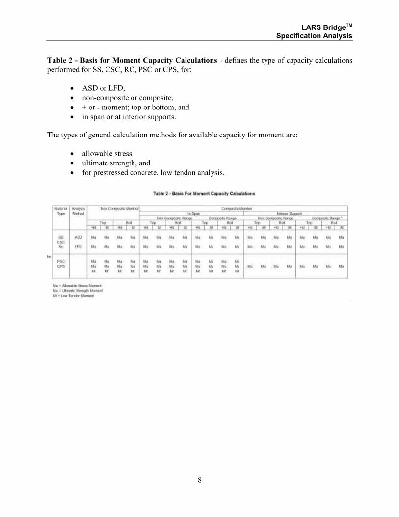
Table 2 - Basis for Moment Capacity Calculations - defines the type of capacity calculations
performed for SS, CSC, RC, PSC or CPS, for:
• ASD or LFD,
• non-composite or composite,
• + or - moment; top or bottom, and
• in span or at interior supports.
The types of general calculation methods for available capacity for moment are:
• allowable stress,
• ultimate strength, and
• for prestressed concrete, low tendon analysis.
LARS BridgeTM Specification Analysis
9
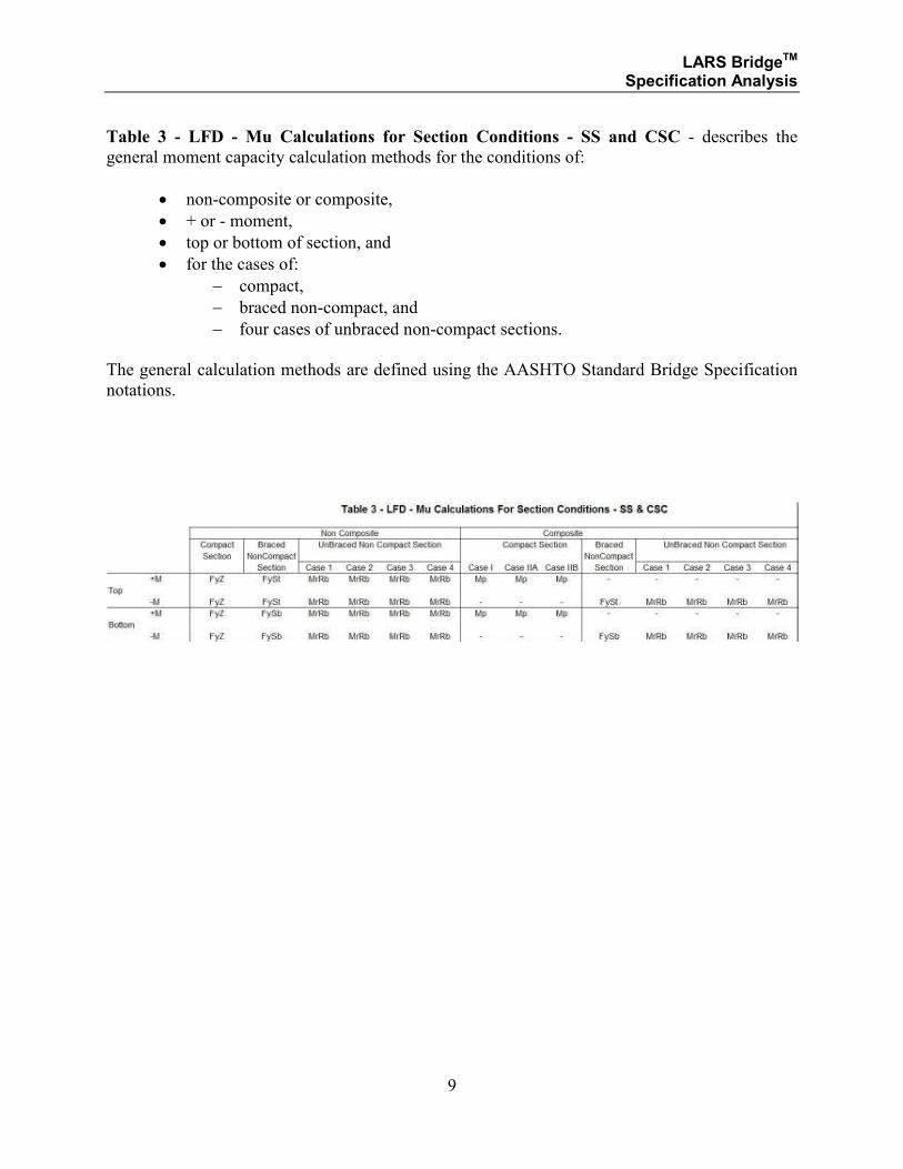
Table 3 - LFD - Mu Calculations for Section Conditions - SS and CSC - describes the
general moment capacity calculation methods for the conditions of:
• non-composite or composite,
• + or - moment,
• top or bottom of section, and
• for the cases of:
− compact,
− braced non-compact, and
− four cases of unbraced non-compact sections.
The general calculation methods are defined using the AASHTO Standard Bridge Specification
notations.
LARS BridgeTM Specification Analysis
10
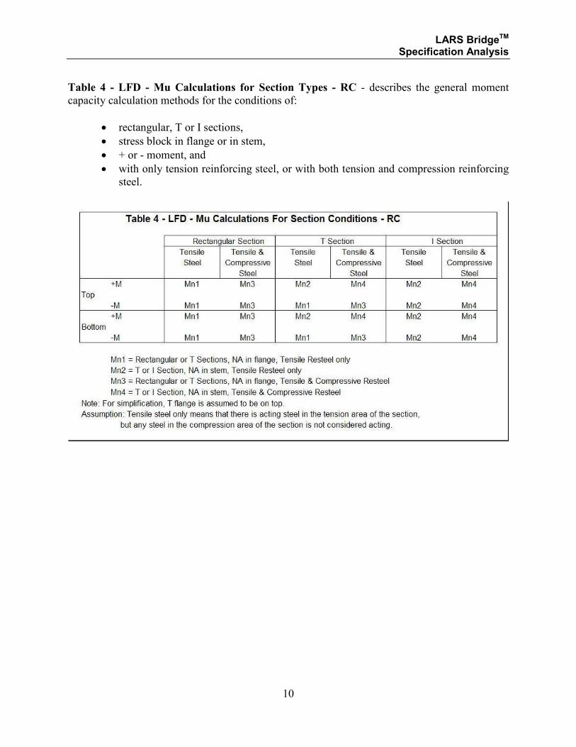
Table 4 - LFD - Mu Calculations for Section Types - RC - describes the general moment
capacity calculation methods for the conditions of:
• rectangular, T or I sections,
• stress block in flange or in stem,
• + or - moment, and
• with only tension reinforcing steel, or with both tension and compression reinforcing
steel.
LARS BridgeTM Specification Analysis
11
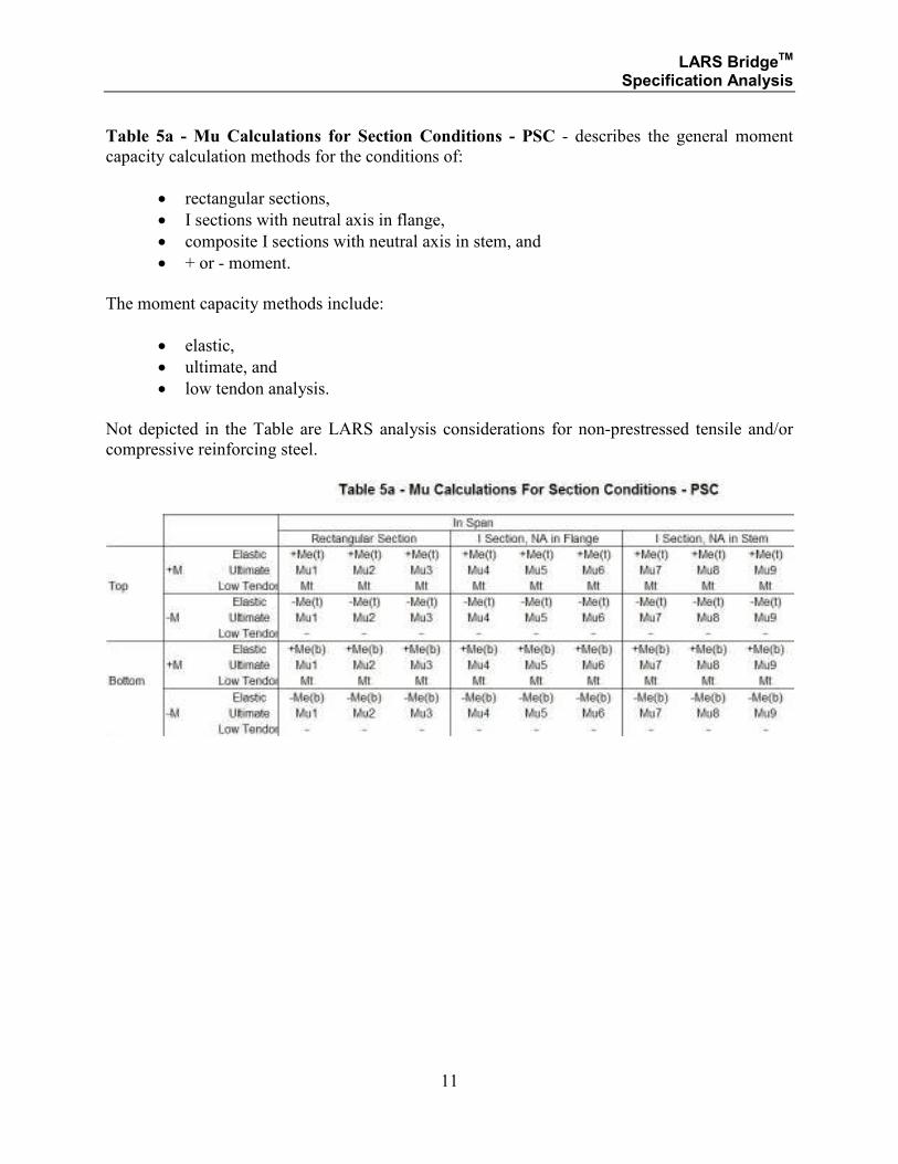
Table 5a - Mu Calculations for Section Conditions - PSC - describes the general moment
capacity calculation methods for the conditions of:
• rectangular sections,
• I sections with neutral axis in flange,
• composite I sections with neutral axis in stem, and
• + or - moment.
The moment capacity methods include:
• elastic,
• ultimate, and
• low tendon analysis.
Not depicted in the Table are LARS analysis considerations for non-prestressed tensile and/or
compressive reinforcing steel.
LARS BridgeTM Specification Analysis
12
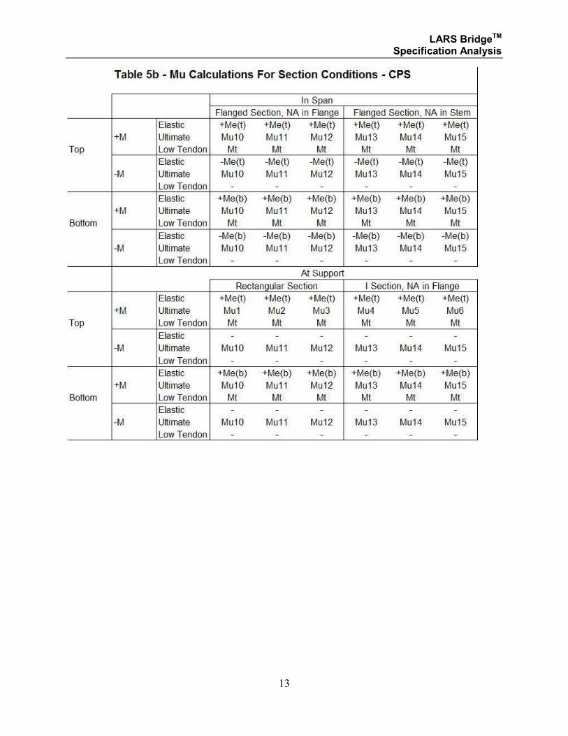
Table 5b - Mu Calculations for Section Conditions - CPS - describes the general moment
capacity calculation methods for the conditions of:
• flanged sections with neutral axis in the flange,
• flanged sections with neutral axis in the stem,
• sections in span or at interior supports, and
• + or - moment.
The moment capacity methods include:
• elastic,
• ultimate, and
• low tendon analysis.
Not depicted in the Table are LARS analysis considerations for non-prestressed tensile and/or
compressive reinforcing steel.
LARS BridgeTM Specification Analysis
13
LARS BridgeTM Specification Analysis
14
SECTION 1
STRUCTURAL STEEL
AND
COMPOSITE STEEL AND CONCRETE
LARS BridgeTM Specification Analysis
15
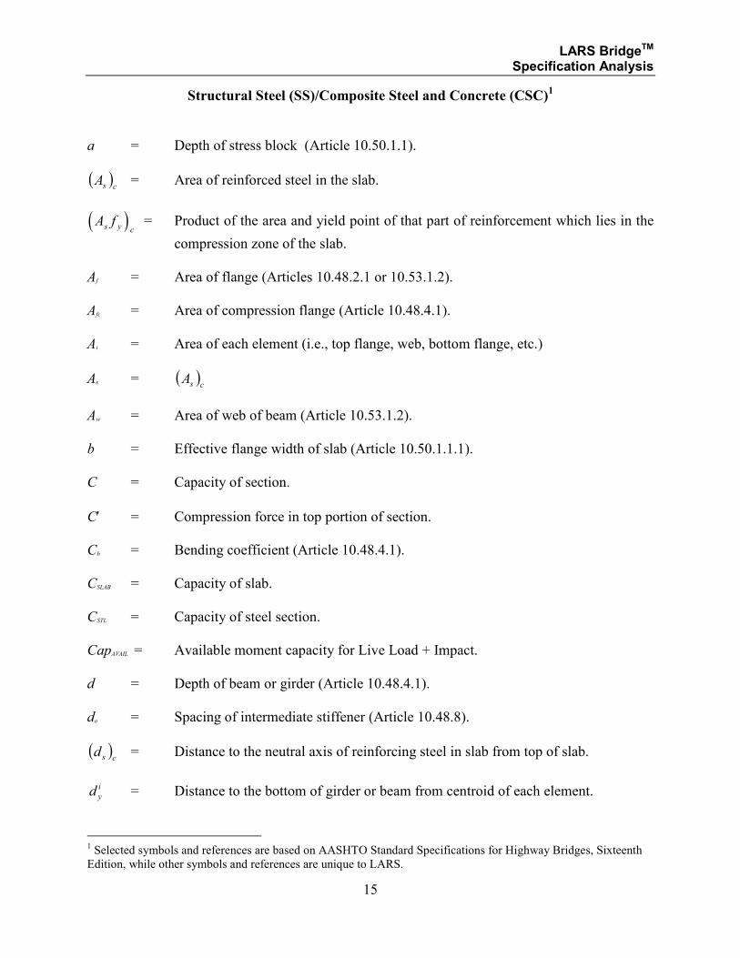
Structural Steel (SS)/Composite Steel and Concrete (CSC)1
a = Depth of stress block (Article 10.50.1.1).
( )csA = Area of reinforced steel in the slab.
( )A fs y c = Product of the area and yield point of that part of reinforcement which lies in the
compression zone of the slab.
Af = Area of flange (Articles 10.48.2.1 or 10.53.1.2).
Afc = Area of compression flange (Article 10.48.4.1).
Ai = Area of each element (i.e., top flange, web, bottom flange, etc.)
As = ( )csA
Aw = Area of web of beam (Article 10.53.1.2).
b = Effective flange width of slab (Article 10.50.1.1.1).
C = Capacity of section.
C′ = Compression force in top portion of section.
Cb = Bending coefficient (Article 10.48.4.1).
CSLAB = Capacity of slab.
CSTL = Capacity of steel section.
CapAVAIL = Available moment capacity for Live Load + Impact.
d = Depth of beam or girder (Article 10.48.4.1).
do = Spacing of intermediate stiffener (Article 10.48.8).
( )csd = Distance to the neutral axis of reinforcing steel in slab from top of slab.
d y
i = Distance to the bottom of girder or beam from centroid of each element.
1 Selected symbols and references are based on AASHTO Standard Specifications for Highway Bridges, Sixteenth
Edition, while other symbols and references are unique to LARS.
LARS BridgeTM Specification Analysis
16
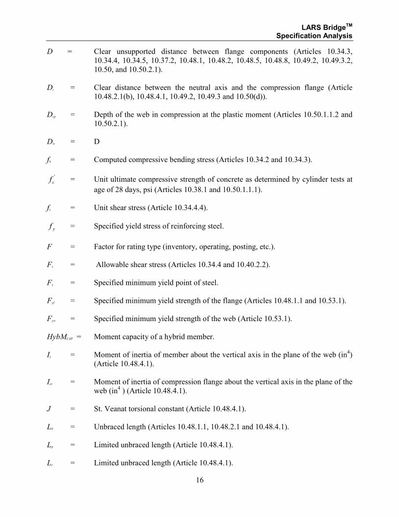
D = Clear unsupported distance between flange components (Articles 10.34.3,
10.34.4, 10.34.5, 10.37.2, 10.48.1, 10.48.2, 10.48.5, 10.48.8, 10.49.2, 10.49.3.2,
10.50, and 10.50.2.1).
Dc = Clear distance between the neutral axis and the compression flange (Article
10.48.2.1(b), 10.48.4.1, 10.49.2, 10.49.3 and 10.50(d)).
Dcp = Depth of the web in compression at the plastic moment (Articles 10.50.1.1.2 and
10.50.2.1).
Dw = D
fb = Computed compressive bending stress (Articles 10.34.2 and 10.34.3).
fc' = Unit ultimate compressive strength of concrete as determined by cylinder tests at
age of 28 days, psi (Articles 10.38.1 and 10.50.1.1.1).
fv = Unit shear stress (Article 10.34.4.4).
f y = Specified yield stress of reinforcing steel.
F = Factor for rating type (inventory, operating, posting, etc.).
Fv = Allowable shear stress (Articles 10.34.4 and 10.40.2.2).
Fy = Specified minimum yield point of steel.
Fyf = Specified minimum yield strength of the flange (Articles 10.48.1.1 and 10.53.1).
Fyw = Specified minimum yield strength of the web (Article 10.53.1).
HybMCAP = Moment capacity of a hybrid member.
Iy = Moment of inertia of member about the vertical axis in the plane of the web (in4)
(Article 10.48.4.1).
Iyc = Moment of inertia of compression flange about the vertical axis in the plane of the
web (in4 ) (Article 10.48.4.1).
J = St. Veanat torsional constant (Article 10.48.4.1).
Lb = Unbraced length (Articles 10.48.1.1, 10.48.2.1 and 10.48.4.1).
Lp = Limited unbraced length (Article 10.48.4.1).
Lr = Limited unbraced length (Article 10.48.4.1).
LARS BridgeTM Specification Analysis
17
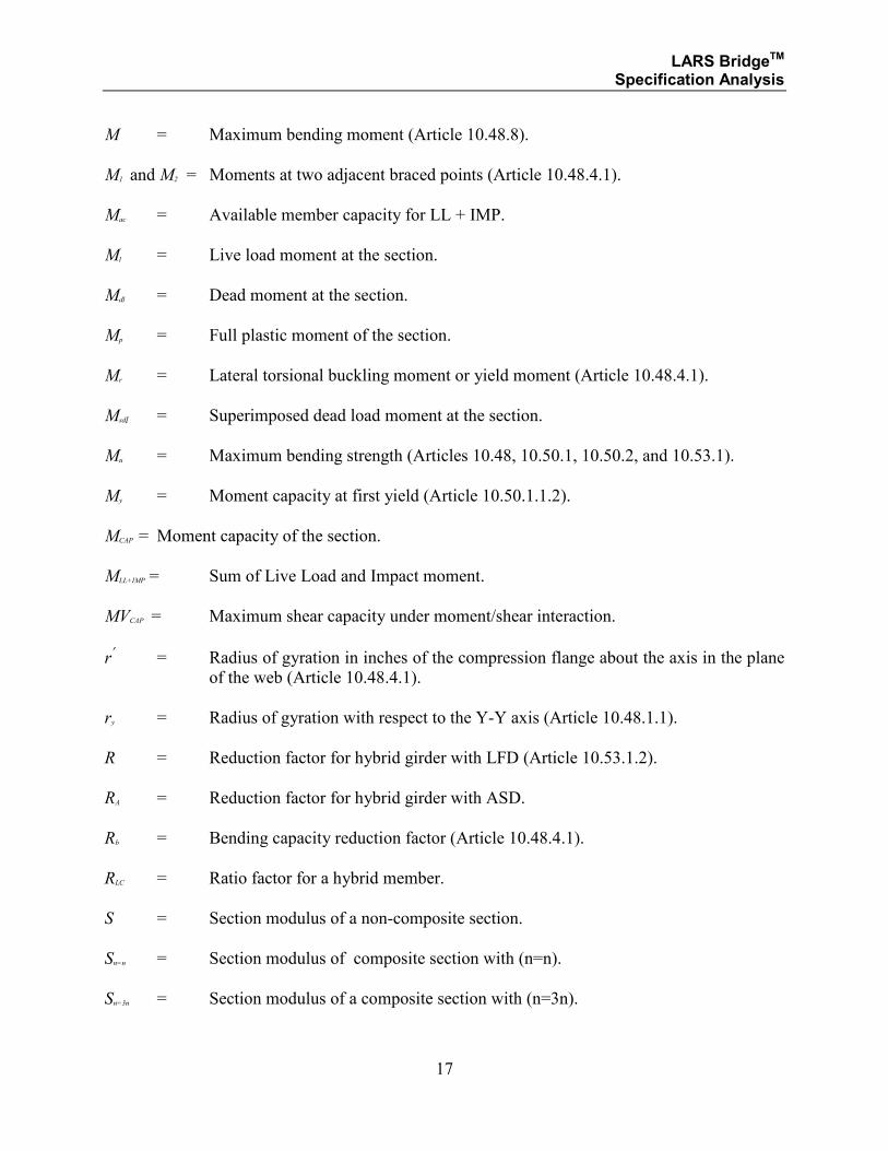
M = Maximum bending moment (Article 10.48.8).
M1 and M2 = Moments at two adjacent braced points (Article 10.48.4.1).
Mac = Available member capacity for LL + IMP.
Ml = Live load moment at the section.
Mdl = Dead moment at the section.
Mp = Full plastic moment of the section.
Mr = Lateral torsional buckling moment or yield moment (Article 10.48.4.1).
Msdl = Superimposed dead load moment at the section.
Mu = Maximum bending strength (Articles 10.48, 10.50.1, 10.50.2, and 10.53.1).
My = Moment capacity at first yield (Article 10.50.1.1.2).
MCAP = Moment capacity of the section.
MLL+IMP = Sum of Live Load and Impact moment.
MVCAP = Maximum shear capacity under moment/shear interaction.
r′
= Radius of gyration in inches of the compression flange about the axis in the plane
of the web (Article 10.48.4.1).
ry = Radius of gyration with respect to the Y-Y axis (Article 10.48.1.1).
R = Reduction factor for hybrid girder with LFD (Article 10.53.1.2).
RA = Reduction factor for hybrid girder with ASD.
Rb = Bending capacity reduction factor (Article 10.48.4.1).
RLC = Ratio factor for a hybrid member.
S = Section modulus of a non-composite section.
Sn=n = Section modulus of composite section with (n=n).
Sn=3n = Section modulus of a composite section with (n=3n).
LARS BridgeTM Specification Analysis
18
Sx = S
Sxc = Section modulus with respect to the compression flange (in3) (Article 10.48.4.1).
tf = Thickness of the flange.
ts = Effective thickness of slab.
ttf = Thickness of top flange (Article 10.50.1.1.1).
tw = Web thickness, in (Articles 10.34.3, 10.34.4, 10.34.5, 10.37.2, 10.48, 10.49.2, and
10.49.3).
V = Shearing force (Article 10.48.8).
Vdl = Dead load shear at a section.
Vsdl = Superimposed dead load shear at a section.
Vu = Maximum shear force (Articles 10.48.8, and 10.53.1.4).
VAVAIL = Available shear capacity for Live Load + Impact.
VCAP = Shear capacity.
VDL = Vdl
VLL+IMP = Sum of Live Load and Impact shear.
VSDL = Vsdl
y−
= Location of steel sections from neutral axis (Article 10.50.1.1.1).
Z = Plastic section modulus (Articles 10.48.1 and 10.53.1.1).
λ = A constant related to limitation of Dc/tw .
β = Area of the web divided by the area of the tension flange, Aw/Af (Articles 10.40.2,
and 10.53.1.2).
ϕ = Distance from the outer edge of the tension flange to the neutral axis divided by
the depth of the steel section (Article 10.40.2).
LARS BridgeTM Specification Analysis
19
α = Inclination angle of a bent up reinforcement or minimum specified yield strength
of the web divided by the minimum specified yield strength of the tension flange
(Article 10.40.2).
ρ = Fyw/Fyf (Article 10.53.1.2).
LARS BridgeTM Specification Analysis
20
SECTION 1.1
STRUCTURAL STEEL
AND
COMPOSITE STEEL AND CONCRETE
ALLOWABLE STRESS DESIGN METHOD
LARS BridgeTM Specification Analysis
21
Structural Steel (SS)/Composite Steel and Concrete (CSC)
The various criteria logic that is used to determine the calculation methods for the above listed
conditions are referenced below by number. The calculation methods and formulae are
referenced by number.
ASD
ASD analysis will be performed for every flexural member that has data sufficient for this
analysis, regardless of whether an LFD analysis is requested.
Non-Composite:
• A member will be considered as non-composite if the member is designed as SS.
• The values for available capacity for LL + IMP and moment capacity for all non-
composite members are calculated by the formulae of MS-1a and MS-1b for non-hybrid
girders, and MH-1a and MH-1b for hybrid girders.
• The radius for all available capacity for LL + IMP and shear capacity for all non-
composite members are calculated by the formulae of VS-1a and VS-1b, and VS2.1a and
VS.1b through VS-2.3a and VS-2.3b.
Composite:
• A member will be considered as composite if the member is designed as CSC, and
concrete slab has been described.
• The values for available capacity for LL + IMP and moment capacity for all composite
members are calculated by the formulae of MS-2a and MS-2b.
LARS BridgeTM Specification Analysis
22
SECTION 1.1.1
STRUCTURAL STEEL
AND
COMPOSITE STEEL AND CONCRETE
ALLOWABLE STRESS DESIGN METHOD
MOMENT ANALYSIS
LARS BridgeTM Specification Analysis
23
Structural Steel (SS)/Composite Steel and Concrete (CSC)
ASD
Moment Analysis Method for SS Member
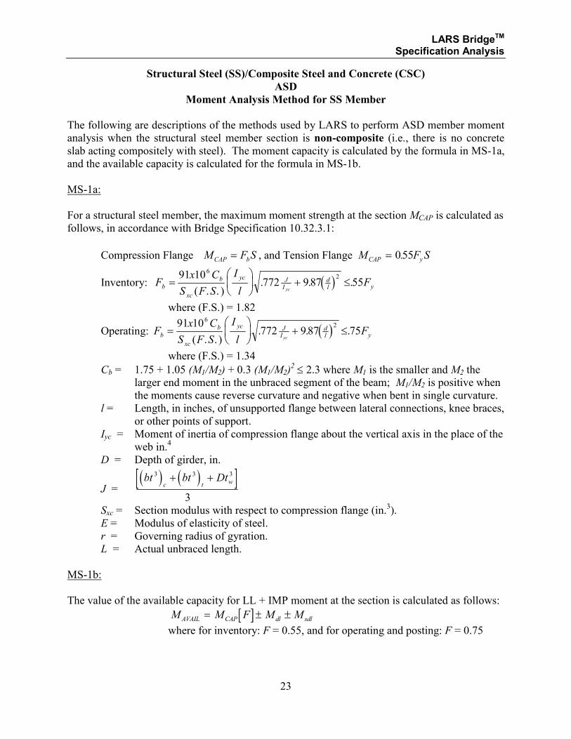
The following are descriptions of the methods used by LARS to perform ASD member moment
analysis when the structural steel member section is non-composite (i.e., there is no concrete
slab acting compositely with steel). The moment capacity is calculated by the formula in MS-1a,
and the available capacity is calculated for the formula in MS-1b.
MS-1a:
For a structural steel member, the maximum moment strength at the section MCAP is calculated as
follows, in accordance with Bridge Specification 10.32.3.1:
Compression Flange SFM bCAP = , and Tension Flange M F SCAP y= 055.
Inventory: ( )Fx C
S F S
I
lFb
b
xc
yc JI
dl yyc
=
+ ≤
91 10772 987 55
62
( . . ). . .
where (F.S.) = 1.82
Operating: ( )Fx C
S F S
I
lFb
b
xc
yc JI
dl yyc
=
+ ≤
91 10772 987 75
62
( . . ). . .
where (F.S.) = 1.34
Cb = 1.75 + 1.05 (M1/M2) + 0.3 (M1/M2)2 ≤ 2.3 where M1 is the smaller and M2 the
larger end moment in the unbraced segment of the beam; M1/M2 is positive when
the moments cause reverse curvature and negative when bent in single curvature.
l = Length, in inches, of unsupported flange between lateral connections, knee braces,
or other points of support.
Iyc = Moment of inertia of compression flange about the vertical axis in the place of the
web in.4
D = Depth of girder, in.
J = ( ) ( )[ ]bt bt Dt
c t w
3 3 3
3
+ +
Sxc = Section modulus with respect to compression flange (in.3).
E = Modulus of elasticity of steel.
r = Governing radius of gyration.
L = Actual unbraced length.
MS-1b:
The value of the available capacity for LL + IMP moment at the section is calculated as follows:
[ ]M M F M MAVAIL CAP dl sdl= ± ±
where for inventory: F = 0.55, and for operating and posting: F = 0.75
LARS BridgeTM Specification Analysis
24
Structural Steel (SS)/Composite Steel and Concrete (CSC)
ASD
Moment Analysis Method for CSC Member
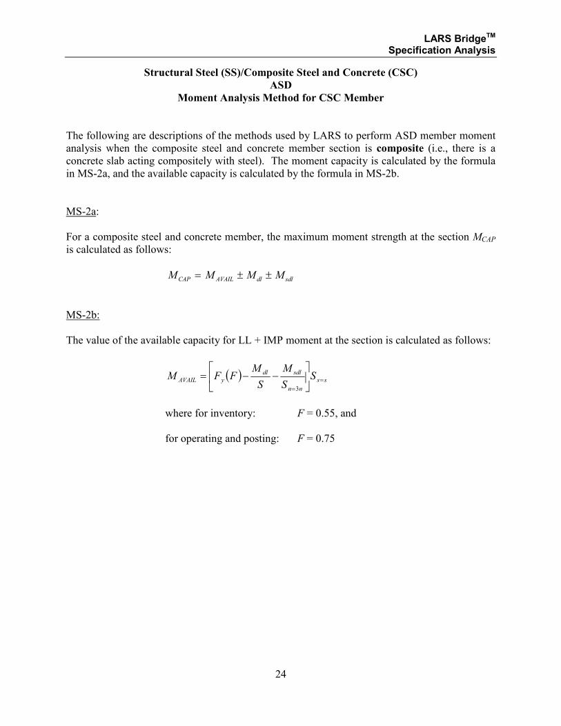
The following are descriptions of the methods used by LARS to perform ASD member moment
analysis when the composite steel and concrete member section is composite (i.e., there is a
concrete slab acting compositely with steel). The moment capacity is calculated by the formula
in MS-2a, and the available capacity is calculated by the formula in MS-2b.
MS-2a:
For a composite steel and concrete member, the maximum moment strength at the section MCAP
is calculated as follows:
M M M MCAP AVAIL dl sdl= ± ±
MS-2b:
The value of the available capacity for LL + IMP moment at the section is calculated as follows:
( ) ss
nn
sdldl
yAVAIL SS
M
S
MFFM =
=
−−=
3
where for inventory: F = 0.55, and
for operating and posting: F = 0.75
LARS BridgeTM Specification Analysis
25
SECTION 1.1.2
STRUCTURAL STEEL
AND
COMPOSITE STEEL AND CONCRETE
ALLOWABLE STRESS DESIGN METHOD
MOMENT ANALYSIS
FOR
HYBRID GIRDERS
LARS BridgeTM Specification Analysis
26
Structural Steel (SS)/Composite Steel and Concrete (CSC)
ASD
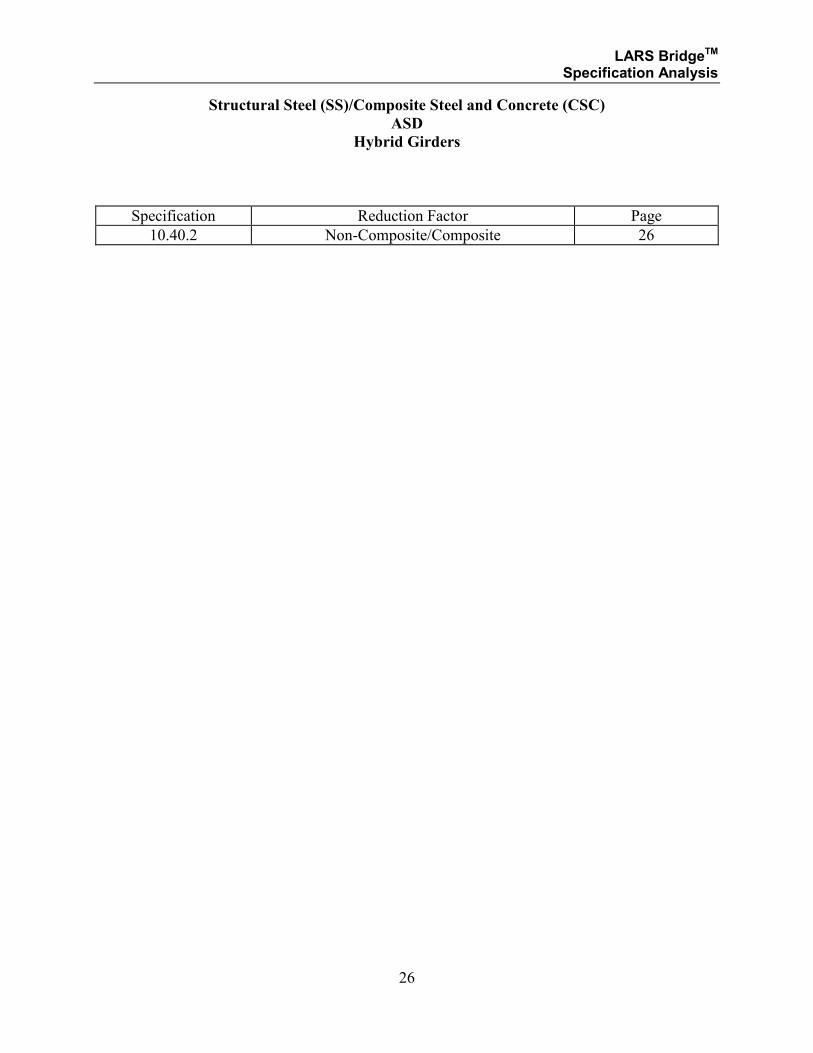
Hybrid Girders
Specification Reduction Factor Page
10.40.2 Non-Composite/Composite 26
LARS BridgeTM Specification Analysis
27
Structural Steel (SS)/Composite Steel and Concrete (CSC)
ASD
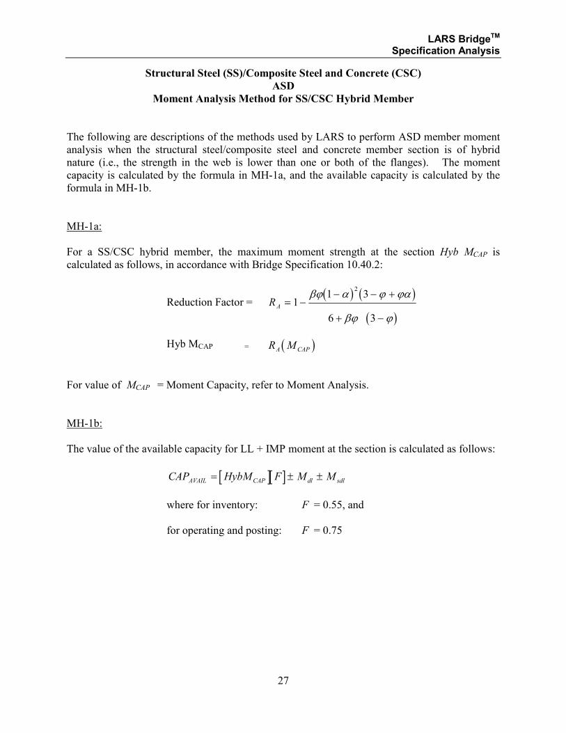
Moment Analysis Method for SS/CSC Hybrid Member
The following are descriptions of the methods used by LARS to perform ASD member moment
analysis when the structural steel/composite steel and concrete member section is of hybrid
nature (i.e., the strength in the web is lower than one or both of the flanges). The moment
capacity is calculated by the formula in MH-1a, and the available capacity is calculated by the
formula in MH-1b.
MH-1a:
For a SS/CSC hybrid member, the maximum moment strength at the section Hyb MCAP is
calculated as follows, in accordance with Bridge Specification 10.40.2:
Reduction Factor = ( ) ( )
( )RA = −
− − +
+ −
11 3
6 3
2βϕ α ϕ ϕα
βϕ ϕ
Hyb MCAP = ( )R MA CAP
For value of MCAP = Moment Capacity, refer to Moment Analysis.
MH-1b:
The value of the available capacity for LL + IMP moment at the section is calculated as follows:
[ ][ ]CAP HybM F M MAVAIL CAP dl sdl= ± ±
where for inventory: F = 0.55, and
for operating and posting: F = 0.75

LARS BridgeTM Specification Analysis
28
SECTION 1.1.3
STRUCTURAL STEEL
AND
COMPOSITE STEEL AND CONCRETE
ALLOWABLE STRESS DESIGN METHOD
SHEAR ANALYSIS
LARS BridgeTM Specification Analysis
29
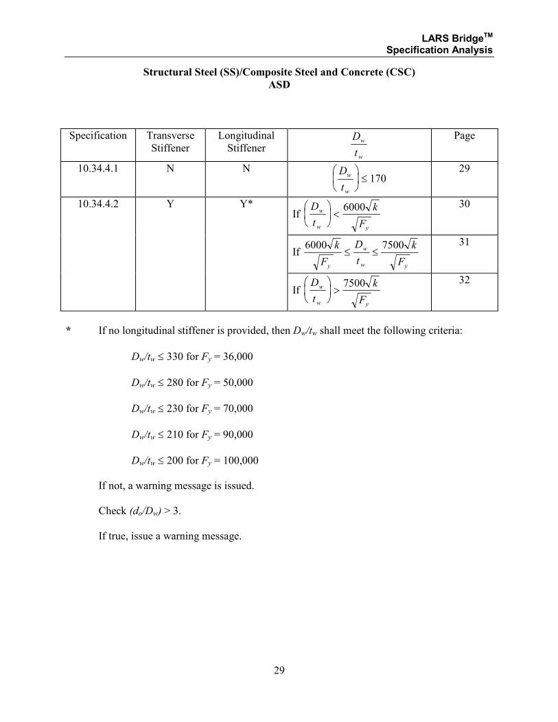
Structural Steel (SS)/Composite Steel and Concrete (CSC)
ASD
Specification Transverse
Stiffener
Longitudinal
Stiffener D
t
w
w
Page
10.34.4.1 N N D
t
w
w
≤ 170
29
10.34.4.2 Y Y* If
D
t
k
F
w
w y
<
6000
30
If
6000 7500k
F
D
t
k
Fy
w
w y
≤ ≤ 31
If
D
t
k
F
w
w y
>
7500
32
* If no longitudinal stiffener is provided, then Dw/tw shall meet the following criteria:
Dw/tw ≤ 330 for Fy = 36,000
Dw/tw ≤ 280 for Fy = 50,000
Dw/tw ≤ 230 for Fy = 70,000
Dw/tw ≤ 210 for Fy = 90,000
Dw/tw ≤ 200 for Fy = 100,000
If not, a warning message is issued.
Check (do/Dw) > 3.
If true, issue a warning message.
LARS BridgeTM Specification Analysis
30
Structural Steel (SS)/Composite Steel and Concrete (CSC)
ASD
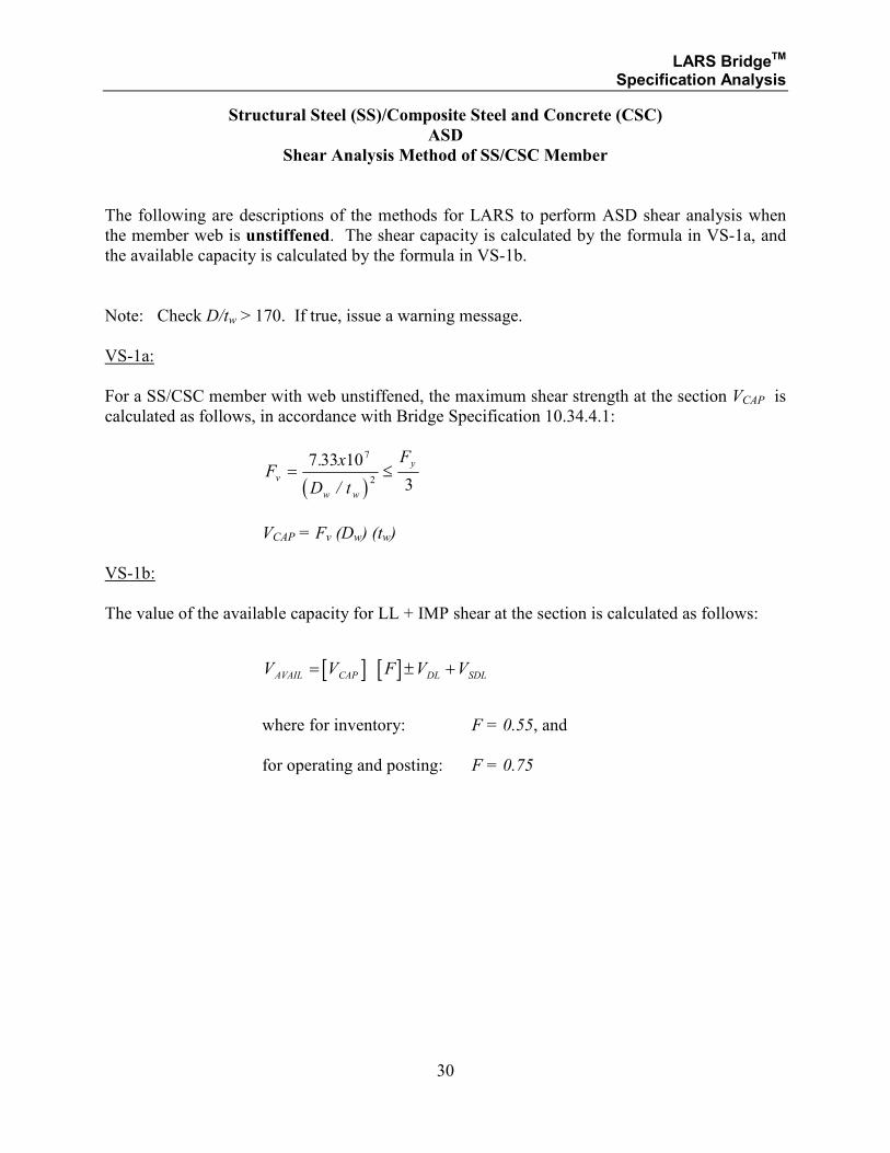
Shear Analysis Method of SS/CSC Member
The following are descriptions of the methods for LARS to perform ASD shear analysis when
the member web is unstiffened. The shear capacity is calculated by the formula in VS-1a, and
the available capacity is calculated by the formula in VS-1b.
Note: Check D/tw > 170. If true, issue a warning message.
VS-1a:
For a SS/CSC member with web unstiffened, the maximum shear strength at the section VCAP is
calculated as follows, in accordance with Bridge Specification 10.34.4.1:
( )
Fx
D t
Fv
w w
y= ≤
7 33 10
3
7
2
.
/
VCAP = Fv (Dw) (tw)
VS-1b:
The value of the available capacity for LL + IMP shear at the section is calculated as follows:
[ ] [ ]V V F V VAVAIL CAP DL SDL= ± +
where for inventory: F = 0.55, and
for operating and posting: F = 0.75
LARS BridgeTM Specification Analysis
31
Structural Steel (SS)/Composite Steel and Concrete (CSC)
ASD
Shear Analysis Method for SS/CSC Member
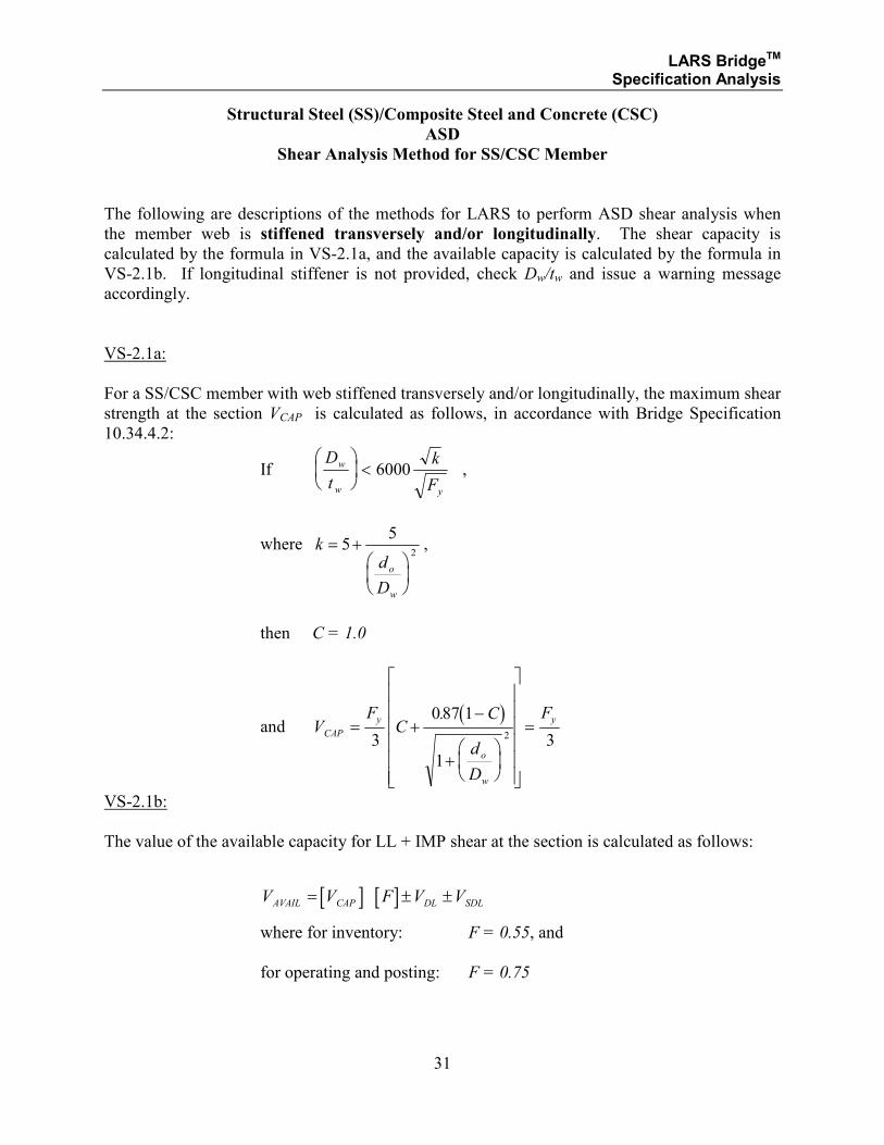
The following are descriptions of the methods for LARS to perform ASD shear analysis when
the member web is stiffened transversely and/or longitudinally. The shear capacity is
calculated by the formula in VS-2.1a, and the available capacity is calculated by the formula in
VS-2.1b. If longitudinal stiffener is not provided, check Dw/tw and issue a warning message
accordingly.
VS-2.1a:
For a SS/CSC member with web stiffened transversely and/or longitudinally, the maximum shear
strength at the section VCAP is calculated as follows, in accordance with Bridge Specification
10.34.4.2:
If D
t
k
F
w
w y
< 6000 ,
where kd
D
o
w
= +
55
2,
then C = 1.0
and ( )
VF
CC
d
D
FCAP
y
o
w
y= +−
+
=3
087 1
1
32
.
VS-2.1b:
The value of the available capacity for LL + IMP shear at the section is calculated as follows:
[ ] [ ]V V F V VAVAIL CAP DL SDL= ± ±
where for inventory: F = 0.55, and
for operating and posting: F = 0.75
LARS BridgeTM Specification Analysis
32
Structural Steel (SS)/Composite Steel and Concrete (CSC)
ASD
Shear Analysis Method for SS/CSC Member
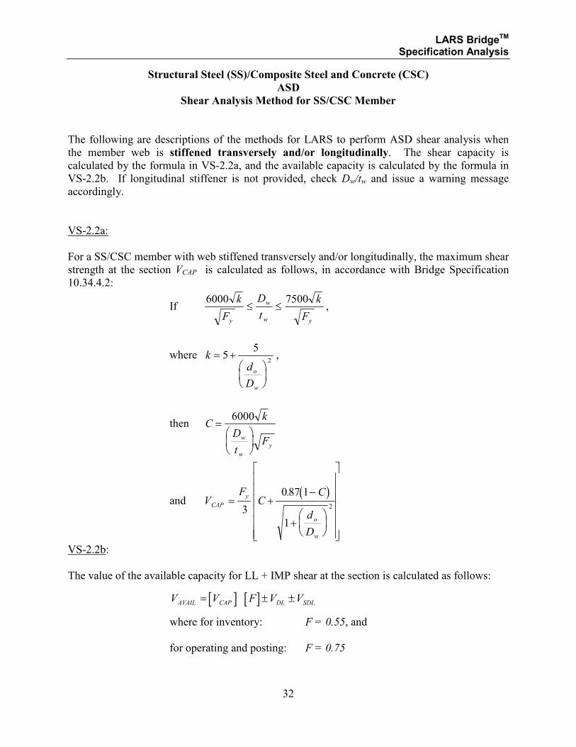
The following are descriptions of the methods for LARS to perform ASD shear analysis when
the member web is stiffened transversely and/or longitudinally. The shear capacity is
calculated by the formula in VS-2.2a, and the available capacity is calculated by the formula in
VS-2.2b. If longitudinal stiffener is not provided, check Dw/tw and issue a warning message
accordingly.
VS-2.2a:
For a SS/CSC member with web stiffened transversely and/or longitudinally, the maximum shear
strength at the section VCAP is calculated as follows, in accordance with Bridge Specification
10.34.4.2:
If 6000 7500k
F
D
t
k
Fy
w
w y
≤ ≤ ,
where kd
D
o
w
= +
55
2,
then Ck
D
tFw
w
y
=
6000
and ( )
VF
CC
d
D
CAP
y
o
w
= +−
+
3
087 1
1
2
.
VS-2.2b:
The value of the available capacity for LL + IMP shear at the section is calculated as follows:
[ ] [ ]V V F V VAVAIL CAP DL SDL= ± ±
where for inventory: F = 0.55, and
for operating and posting: F = 0.75
LARS BridgeTM Specification Analysis
33
Structural Steel (SS)/Composite Steel and Concrete (CSC)
ASD
Shear Analysis Method for SS/CSC Member
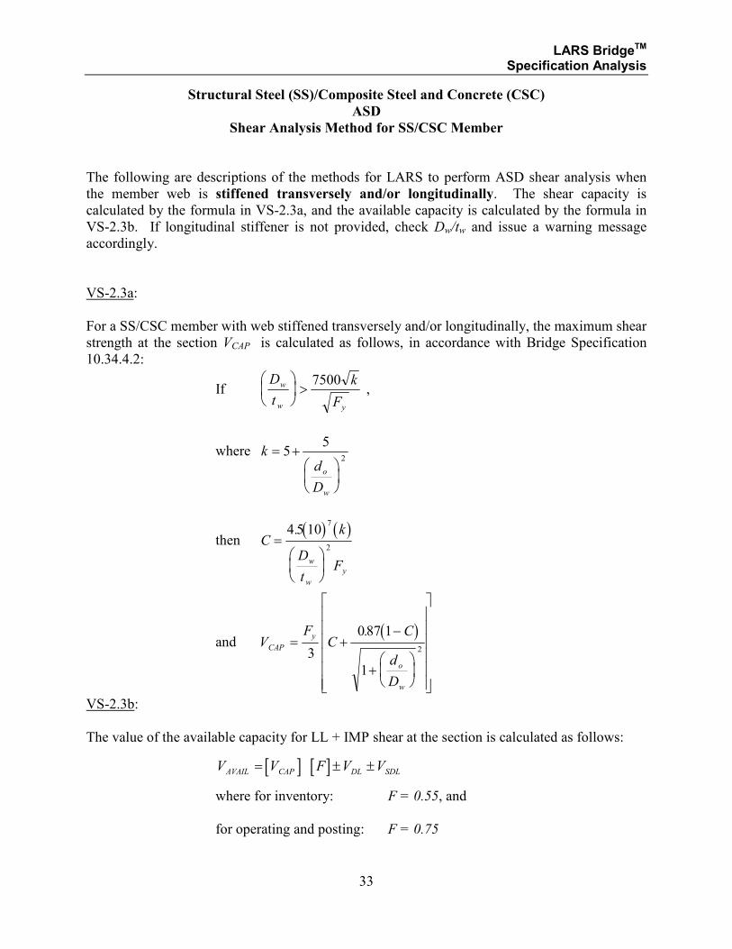
The following are descriptions of the methods for LARS to perform ASD shear analysis when
the member web is stiffened transversely and/or longitudinally. The shear capacity is
calculated by the formula in VS-2.3a, and the available capacity is calculated by the formula in
VS-2.3b. If longitudinal stiffener is not provided, check Dw/tw and issue a warning message
accordingly.
VS-2.3a:
For a SS/CSC member with web stiffened transversely and/or longitudinally, the maximum shear
strength at the section VCAP is calculated as follows, in accordance with Bridge Specification
10.34.4.2:
If D
t
k
F
w
w y
>
7500 ,
where kd
D
o
w
= +
55
2
then ( ) ( )
Ck
D
tFw
w
y
=
4 5 107
2
.
and ( )
VF
CC
d
D
CAP
y
o
w
= +−
+
3
087 1
1
2
.
VS-2.3b:
The value of the available capacity for LL + IMP shear at the section is calculated as follows:
[ ] [ ]V V F V VAVAIL CAP DL SDL= ± ±
where for inventory: F = 0.55, and
for operating and posting: F = 0.75
LARS BridgeTM Specification Analysis
34
Structural Steel (SS)/Composite Steel and Concrete (CSC)
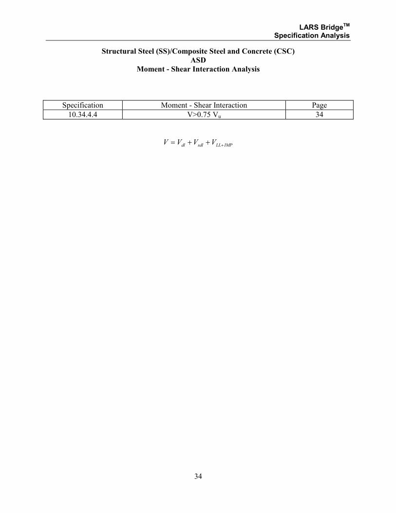
ASD
Moment - Shear Interaction Analysis
Specification Moment - Shear Interaction Page
10.34.4.4 V>0.75 Vu 34
V V V Vdl sdl LL IMP= + + +
LARS BridgeTM Specification Analysis
35
Structural Steel (SS)/Composite Steel and Concrete (CSC)
ASD
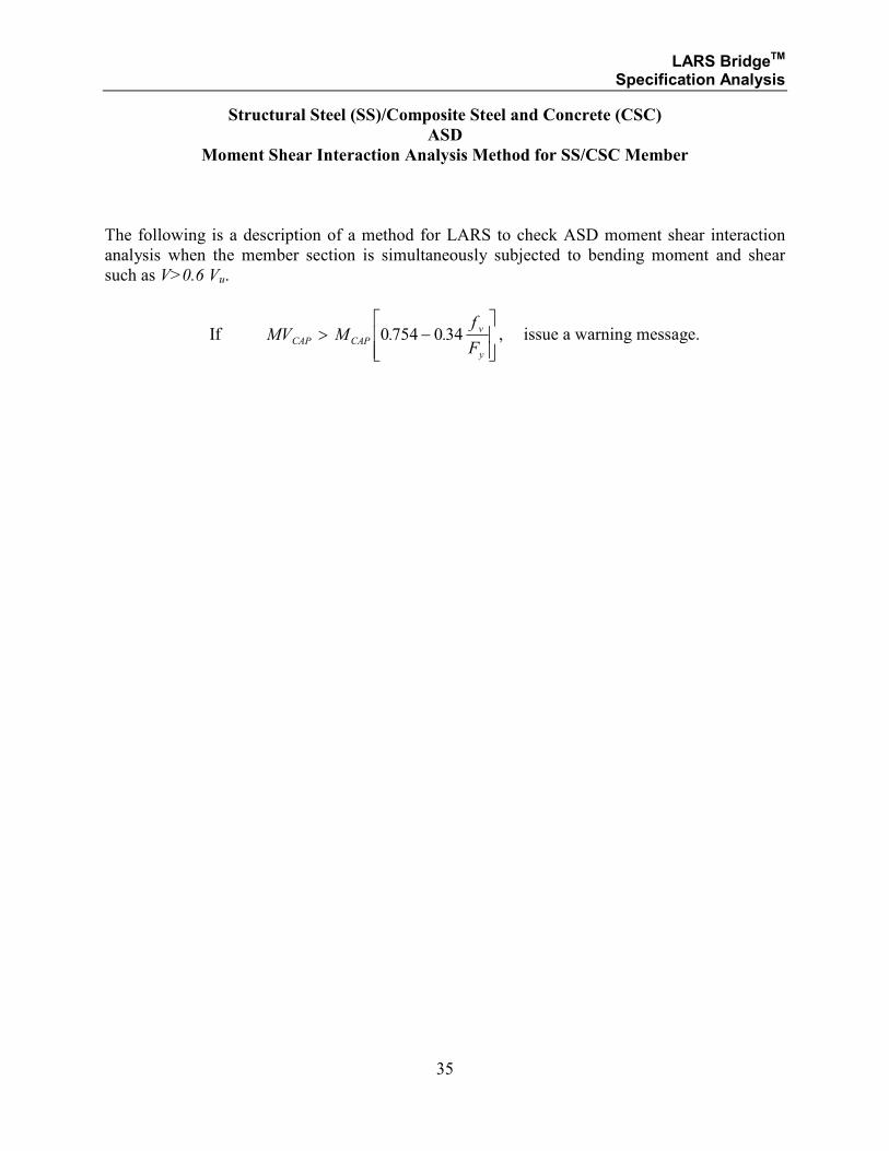
Moment Shear Interaction Analysis Method for SS/CSC Member
The following is a description of a method for LARS to check ASD moment shear interaction
analysis when the member section is simultaneously subjected to bending moment and shear
such as V>0.6 Vu.
If MV Mf
FCAP CAP
v
y
> −
0 754 0 34. . , issue a warning message.
LARS BridgeTM Specification Analysis
36
Structural Steel (SS)/Composite Steel and Concrete (CSC)
ASD
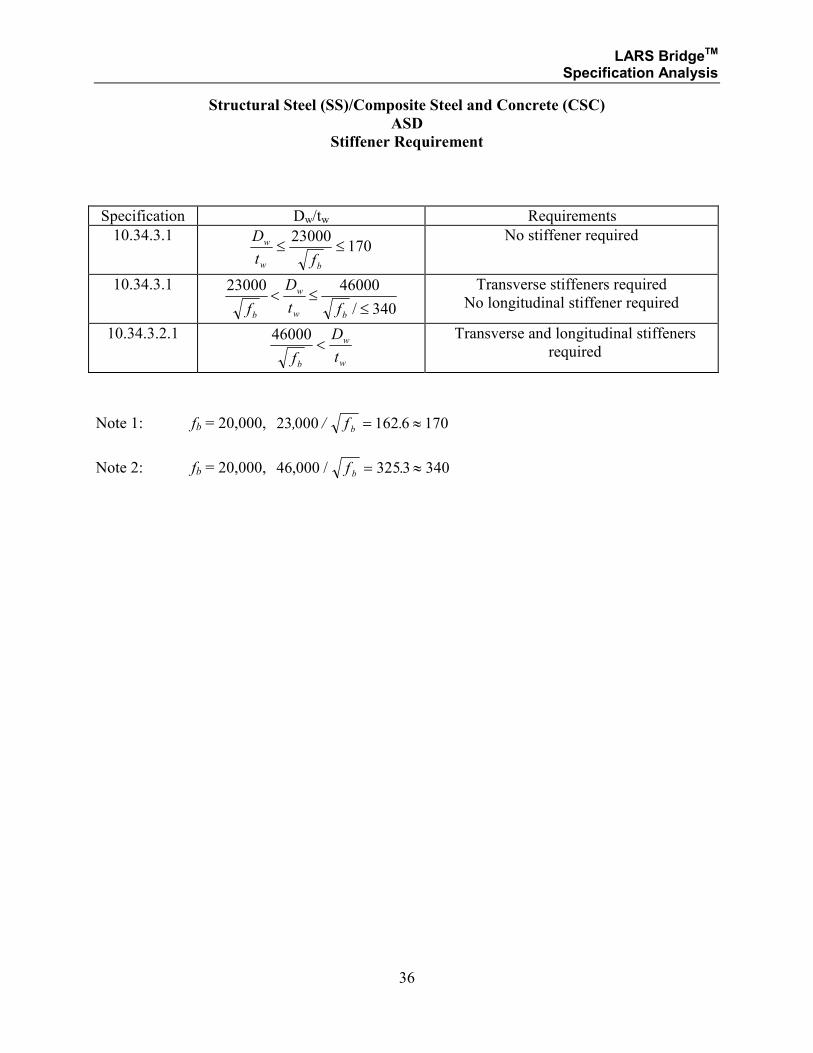
Stiffener Requirement
Specification Dw/tw Requirements
10.34.3.1 170
23000≤≤
bw
w
ft
D
No stiffener required
10.34.3.1
340/
4600023000
≤≤<
bw
w
b ft
D
f
Transverse stiffeners required
No longitudinal stiffener required
10.34.3.2.1
w
w
bt
D
f<
46000
Transverse and longitudinal stiffeners
required
Note 1: fb = 20,000, 23 000 162 6 170, / .f b = ≈
Note 2: fb = 20,000, 46 000 3253 340, / .f b = ≈
LARS BridgeTM Specification Analysis
37
SECTION 1.2
STRUCTURAL STEEL
AND
COMPOSITE STEEL AND CONCRETE
LOAD FACTOR DESIGN METHOD
LARS BridgeTM Specification Analysis
38
Structural Steel (SS)/Composite Steel and Concrete (CSC)
LFD
Qualifications for Determining Analysis Method for Member
The following are descriptions of the qualifications to determine the methods for LARS to
perform LFD member analysis. These qualifications are derived from the AASHTO Standard
Specifications for Highway Bridges, Sixteenth Edition, 1996. The qualifications for analysis
selection are listed separately for each LFD condition, along with references to the appropriate
Specification Number. The LFD analysis types are as follows:
• Non-Composite
• Compact
• Braced Non-Compact
• Unbraced Non-Compact
• Composite
• Compact
• Non-Compact
LARS BridgeTM Specification Analysis
39
Structural Steel (SS)/Composite Steel and Concrete (CSC)
LFD
The various criteria logic that is used to determine the calculation methods for the above listed
conditions are referenced below by number. The calculation methods and formulae are
referenced by number.
Non-Composite:
A member will be considered as non-composite if it is designated as SS.
1. Compact
• The criteria to determine whether or not a member is to be analyzed by non-composite,
compact methods is determined by the logic and calculations shown on page 42.
• The values for available capacity for LL + IMP and moment capacity and for non-
composite, compact members are calculated by the formulae discussed under SS-
M1and SS-M1b on page 45.
2. Braced Non-Compact
• The criteria to determine whether or not a member is to be analyzed by non-
composite, braced, non-compact methods is determined by the logic and calculations
shown on page 43.
• The values for available capacity for LL + IMP and moment capacity for non-
composite, braced, non-compact members are calculated by the formulae discussed
under SS-M2a and SS-M2b on page 45.
3. Unbraced Non-Compact
• The criteria to determine whether or not a member is to be analyzed by non-
composite, unbraced, non-compact methods is determined by the logic and
calculations shown on page 44.
• The values for available capacity for LL + IMP and moment capacity for non-
composite, unbraced, non-compact members are calculated by the formulae discussed
under SS-M3a and SS-M3b on page 48, where Mr used in SS-M3a is computed for
the controlling case (I through IV) outlined under SS-M3 on pages 1-46 and 1-47.
LARS BridgeTM Specification Analysis
40
Composite:
A member will be considered as composite if the concrete slab has been described.
1. Compact
• The criteria to determine whether or not a member is to be analyzed by composite,
compact methods is determined by the logic and calculations shown on page 1-50 to
1-55.
• The values for available capacity for LL + IMP and moment capacity and for
composite, compact members are calculated by the formulae discussed in CSC-M1a
and CSC-M1b on pages 1-56 and 1-57.
2. Braced Non-Compact
• The criteria to determine whether or not a member is to be analyzed by composite,
braced, non-compact methods is determined by the logic and calculations shown on
page 1-50 and 1-57.
• The values for available capacity for LL + IMP and moment capacity for composite,
braced, non-compact members are calculated by the formulae discussed in CSC-M2a
and CSC-M2b on page 1-58.
3. Unbraced Non-Compact
• The criteria to determine whether or not a member is to be analyzed by composite,
unbraced, non-compact methods is determined by the logic and calculations of 1-46
and 1-47.
• The values for available capacity for LL + IMP and moment capacity for composite,
unbraced, non-compact members are calculated by the formulae of 1-48.
LARS BridgeTM Specification Analysis
41
SECTION 1.2.1
STRUCTURAL STEEL
LOAD FACTOR DESIGN METHOD
MOMENT ANALYSIS
FOR:
• COMPACT SECTION
• BRACED NON-COMPACT
• UNBRACED NON-COMPACT
LARS BridgeTM Specification Analysis
42
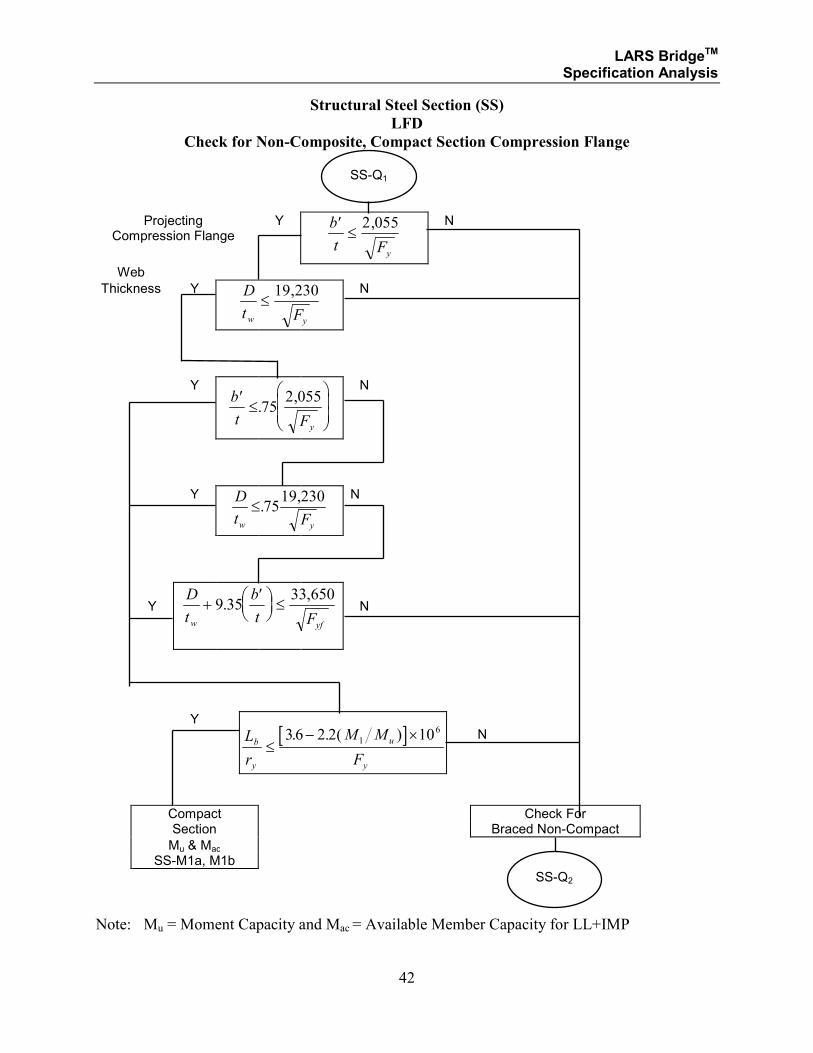
Structural Steel Section (SS)
LFD
Check for Non-Composite, Compact Section Compression Flange
Projecting Compression Flange
Y ′≤
b
t Fy
2 055,
N
Web
Thickness Y D
t Fw y
≤19 230,
N
Y ′≤
b
t Fy
.,
752 055
N
Y D
t Fw y
≤.,
7519 230
N
Y
D
t
b
t Fw yf
+′
≤9 35
33 650.
,
N
Y
[ ]L
r
M M
F
b
y
u
y
≤− ×36 2 2 101
6. . ( )
N
Compact Check For Section Braced Non-Compact
Mu & Mac SS-M1a, M1b
Note: Mu = Moment Capacity and Mac = Available Member Capacity for LL+IMP
SS-Q1
SS-Q2
LARS BridgeTM Specification Analysis
43
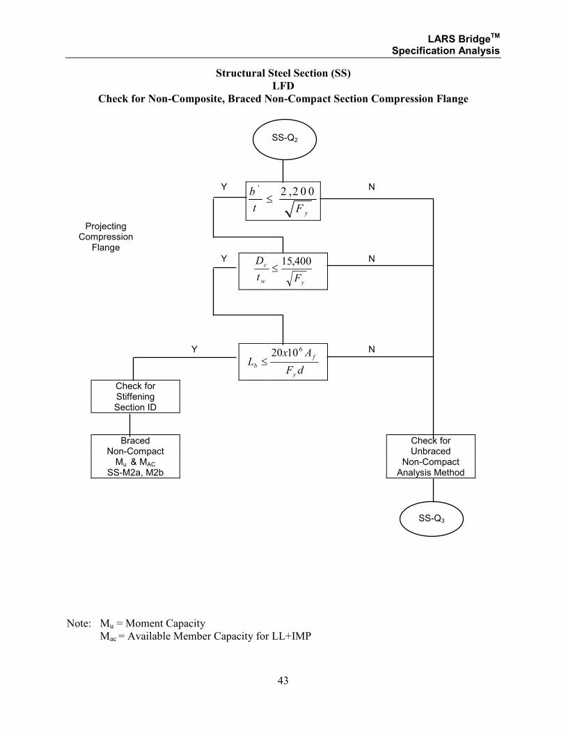
Structural Steel Section (SS)
LFD
Check for Non-Composite, Braced Non-Compact Section Compression Flange
Y b
t F y
' ,≤
2 2 0 0
N
Projecting Compression
Flange
Y D
t F
c
w y
≤15 400,
N
Y
Lx A
F db
f
y
≤20 10 6
N
Check for Stiffening Section ID
Braced Check for Non-Compact Unbraced Mu & MAC Non-Compact SS-M2a, M2b Analysis Method
Note: Mu = Moment Capacity
Mac = Available Member Capacity for LL+IMP
SS-Q2
SS-Q3
LARS BridgeTM Specification Analysis
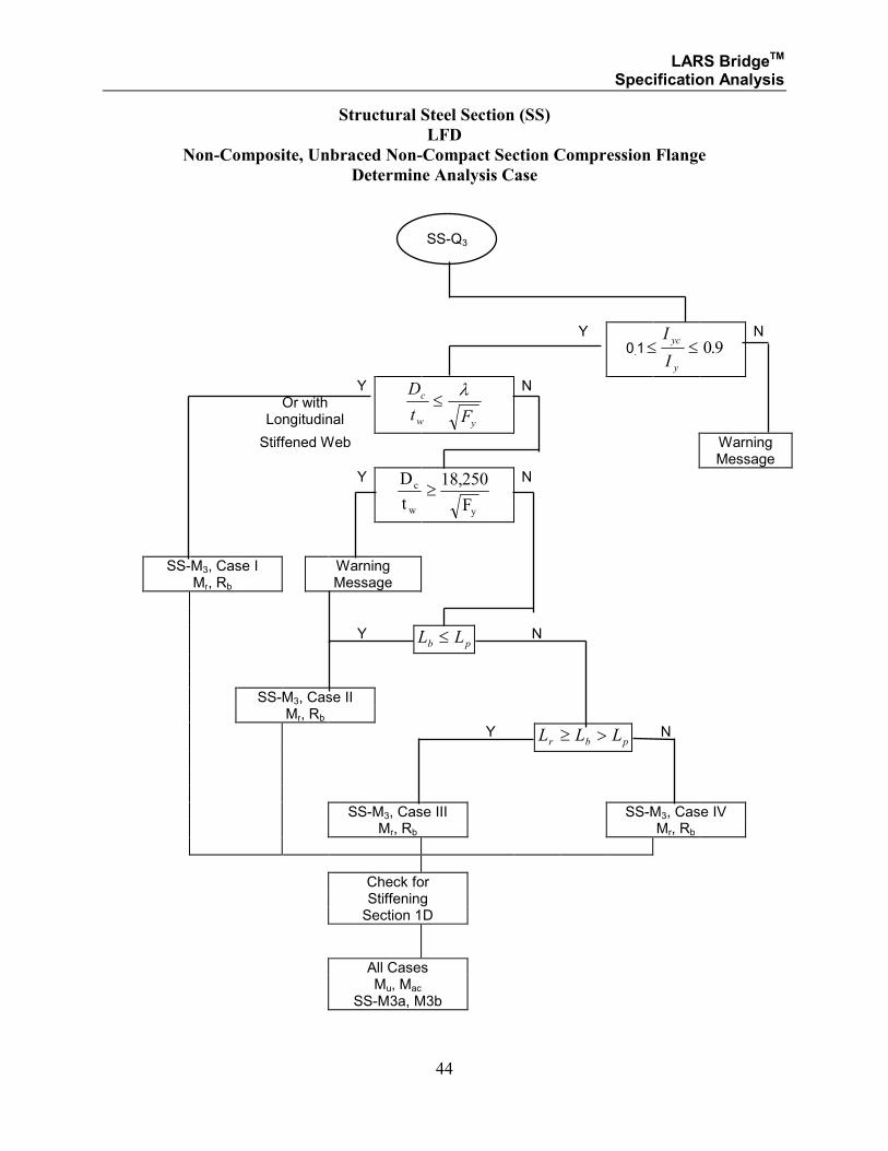
44
Structural Steel Section (SS)
LFD
Non-Composite, Unbraced Non-Compact Section Compression Flange
Determine Analysis Case
Y 0.1≤ ≤
I
I
yc
y
0 9. N
Y Or with
Longitudinal
D
t F
c
w y
≤λ
N
Stiffened Web Warning Message
Y D
t F
c
w y
≥18 250,
N
SS-M3, Case I Warning Mr, Rb Message
Y L Lb p≤ N
SS-M3, Case II Mr, Rb
Y L L Lr b p≥ > N
SS-M3, Case III SS-M3, Case IV Mr, Rb Mr, Rb
Check for Stiffening Section 1D
All Cases Mu, Mac SS-M3a, M3b
SS-Q3
LARS BridgeTM Specification Analysis
45
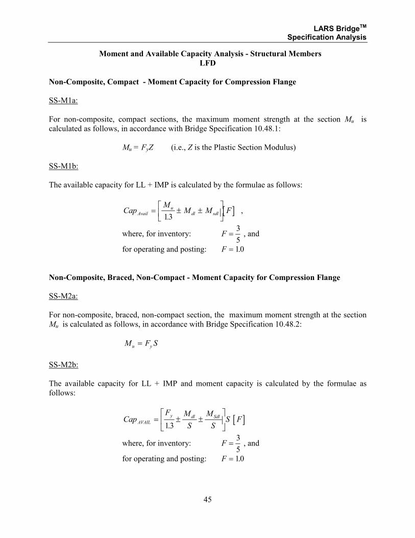
Moment and Available Capacity Analysis - Structural Members
LFD
Non-Composite, Compact - Moment Capacity for Compression Flange
SS-M1a:
For non-composite, compact sections, the maximum moment strength at the section Mu is
calculated as follows, in accordance with Bridge Specification 10.48.1:
Mu = FyZ (i.e., Z is the Plastic Section Modulus)
SS-M1b:
The available capacity for LL + IMP is calculated by the formulae as follows:
[ ]CapM
M M FAvail
u
dl sdl= ± ±
13.
,
where, for inventory: F =3
5 , and
for operating and posting: F = 10.
Non-Composite, Braced, Non-Compact - Moment Capacity for Compression Flange
SS-M2a:
For non-composite, braced, non-compact section, the maximum moment strength at the section
Mu is calculated as follows, in accordance with Bridge Specification 10.48.2:
M F Su y=
SS-M2b:
The available capacity for LL + IMP and moment capacity is calculated by the formulae as
follows:
[ ]CapF M
S
M
SS FAVAIL
y dl Sdl= ± ±
13.
where, for inventory: F =3
5 , and
for operating and posting: F = 10.
LARS BridgeTM Specification Analysis
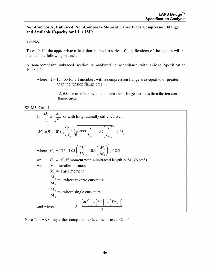
46
Non-Composite, Unbraced, Non-Compact - Moment Capacity for Compression Flange
and Available Capacity for LL + IMP
SS-M3:
To establish the appropriate calculation method, a series of qualifications of the section will be
made in the following manner.
A non-composite unbraced section is analyzed in accordance with Bridge Specification
10.48.4.1:
where λ = 15,400 for all members with a compression flange area equal to or greater
than the tension flange area.
= 12,500 for members with a compression flange area less than the tension
flange area.
SS-M3, Case I
If D
t F
c
w y
≤λ
or with longitudinally stiffened web,
M x CI
L
J
I
d
LMr b
yc
b yc b
y=
+
≤91 10 0 772 9 876
2
. .
where CM
M
M
Mb = +
+
≤175 105 0 3 2 31
2
1
2
. . . , . 2
,
or Cb = 10. , if moment within unbraced length ≤ M s (Note*)
with M1= smaller moment
M 2 = larger moment
M
M
1
2
= + where reverse curvature
M
M
1
2
= - where single curvature
and where [ ] [ ] ][ ]
Jbt bt Dt
b tw
=+ +3 3 3
3
Note *: LARS may either compute the Cb value or use a Cb = 1
LARS BridgeTM Specification Analysis
47
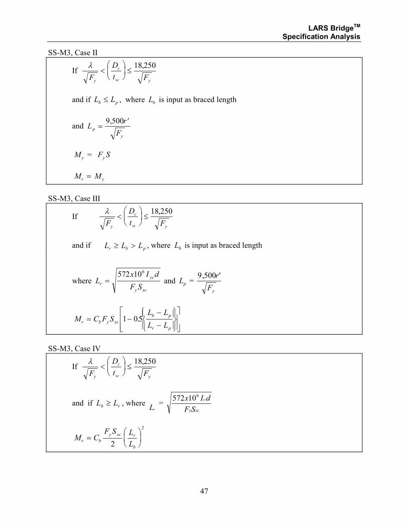
SS-M3, Case II
If λF
D
t Fy
c
w y
<
≤
18 250,
and if L Lb p≤ , where Lb is input as braced length
and Lr
Fp
y
=′9 500,
M y = F Sy
M Mr y=
SS-M3, Case III
If λF
D
t Fy
c
w y
<
≤
18 250,
and if L L Lr b p≥ > , where Lb is input as braced length
where Lx I d
F Sr
yc
y xc
=572 106
and Lp = 9 500, 'r
Fy
M C F SL L
L Lr b y xc
b p
r p
= −−
−
1 05.
SS-M3, Case IV
If λF
D
t Fy
c
w y
<
≤
18 250,
and if L Lb r≥ , where rL =
572 106x I d
F S
yc
y xc
M CF S L
Lr b
y xc r
b
=
2
2
LARS BridgeTM Specification Analysis
48
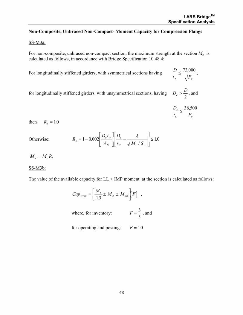
Non-Composite, Unbraced Non-Compact- Moment Capacity for Compression Flange
SS-M3a:
For non-composite, unbraced non-compact section, the maximum strength at the section Mu is
calculated as follows, in accordance with Bridge Specification 10.48.4:
For longitudinally stiffened girders, with symmetrical sections having D
t Fw y
≤73 000,
,
for longitudinally stiffened girders, with unsymmetrical sections, having DD
c >2, and
D
t F
c
w y
≤36 500,
then Rb = 10.
Otherwise: RD t
A
D
t M Sb
c w
fc
c
w r xc
= −
−
≤1 0 002 10.
/.
λ
M M Ru r b=
SS-M3b:
The value of the available capacity for LL + IMP moment at the section is calculated as follows:
[ ]CapM
M M FAvail
u
dl sdl= ± ±
13.
,
where, for inventory: F =3
5 , and
for operating and posting: F = 10.
LARS BridgeTM Specification Analysis
49
SECTION 1.2.2
COMPOSITE STRUCTURAL STEEL AND CONCRETE
LOAD FACTOR DESIGN METHODS
MOMENT ANALYSIS
FOR:
• COMPOSITE COMPACT SECTIONS
• BRACED, NON-COMPACT SECTIONS
LARS BridgeTM Specification Analysis
50
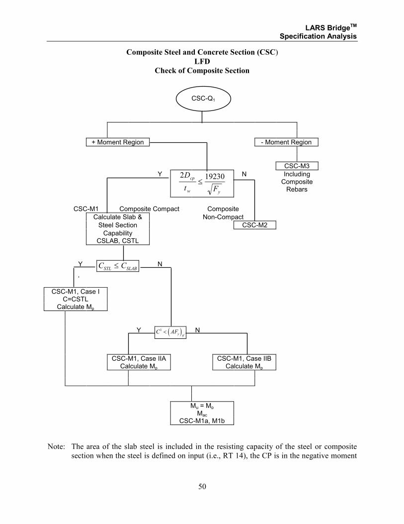
Composite Steel and Concrete Section (CSC)
LFD
Check of Composite Section
+ Moment Region - Moment Region
CSC-M3
Y 2 19230D
t F
cp
w y
≤
N Including Composite Rebars
CSC-M1 Composite Compact Composite
Calculate Slab & Non-Compact
Steel Section CSC-M2
Capability CSLAB, CSTL
Y C CSTL SLAB≤ N
CSC-M1, Case I C=CSTL
Calculate Mp
Y ( )C AFy tf
1 < N
CSC-M1, Case IIA CSC-M1, Case IIB Calculate Mp Calculate Mp
Mu = Mp Mac CSC-M1a, M1b
Note: The area of the slab steel is included in the resisting capacity of the steel or composite
section when the steel is defined on input (i.e., RT 14), the CP is in the negative moment
CSC-Q1
LARS BridgeTM Specification Analysis
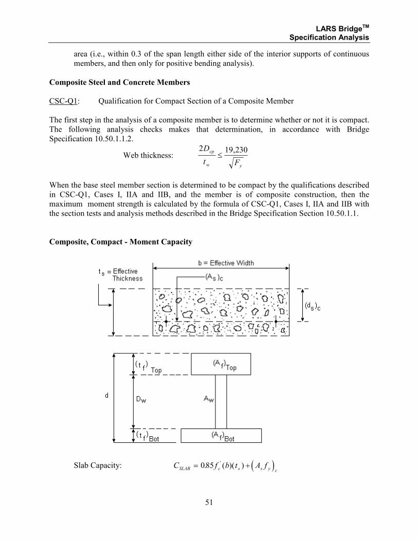
51
area (i.e., within 0.3 of the span length either side of the interior supports of continuous
members, and then only for positive bending analysis).
Composite Steel and Concrete Members
CSC-Q1: Qualification for Compact Section of a Composite Member
The first step in the analysis of a composite member is to determine whether or not it is compact.
The following analysis checks makes that determination, in accordance with Bridge
Specification 10.50.1.1.2.
Web thickness: 2 19 230D
t F
cp
w y
≤,
When the base steel member section is determined to be compact by the qualifications described
in CSC-Q1, Cases I, IIA and IIB, and the member is of composite construction, then the
maximum moment strength is calculated by the formula of CSC-Q1, Cases I, IIA and IIB with
the section tests and analysis methods described in the Bridge Specification Section 10.50.1.1.
Composite, Compact - Moment Capacity
Slab Capacity: ( )C f b t A fSLAB c s s y c= +085. ( )( )'
LARS BridgeTM Specification Analysis
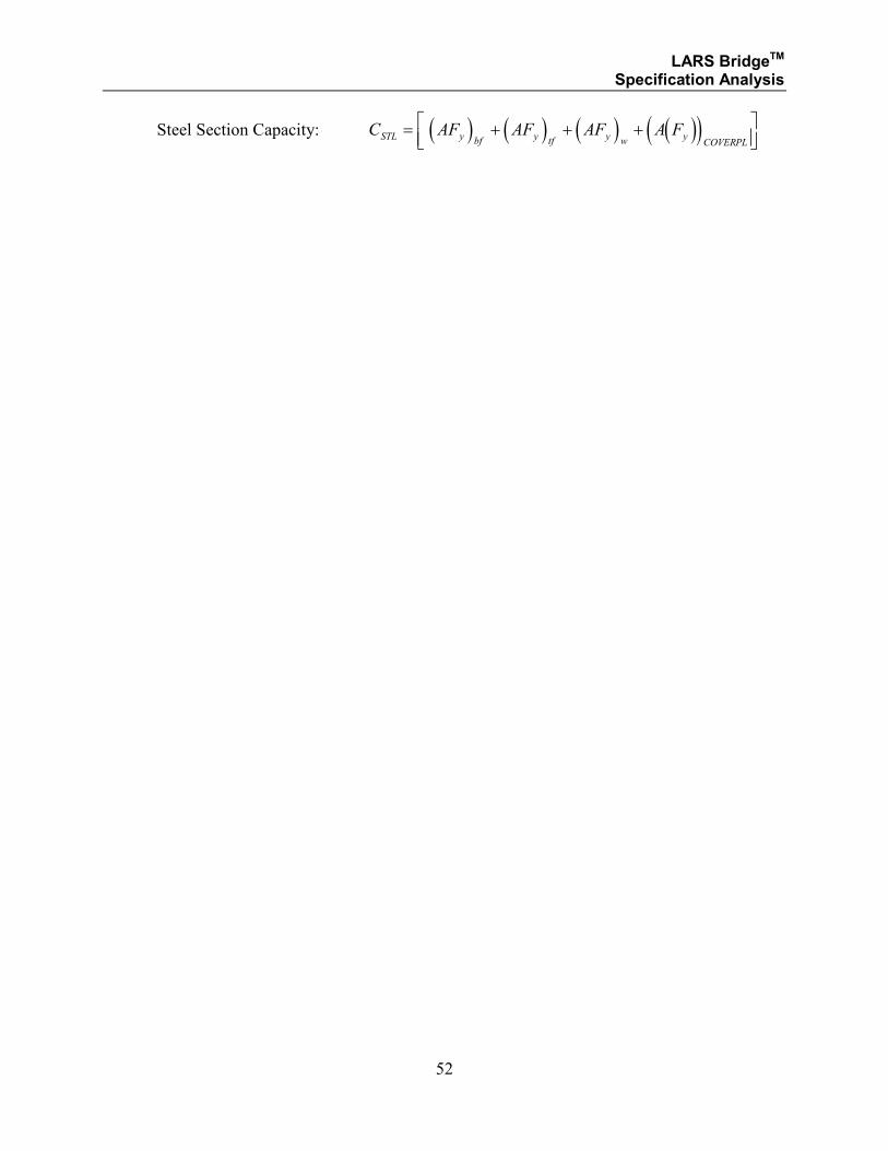
52
Steel Section Capacity: ( ) ( ) ( ) ( )( )C AF AF AF A FSTL y bf y tf y w yCOVERPL
= + + +
LARS BridgeTM Specification Analysis
53
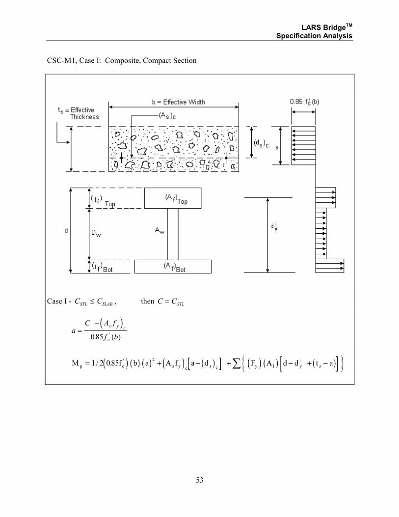
CSC-M1, Case I: Composite, Compact Section
Case I - C CSTL SLAB≤ , then C CSTL=
( )
aC A f
f b
s y c
c
=−
085. ( )'
( ) ( ) ( ) ( ) ( )[ ] ( ) ( ) ( )[ ]{ }M f b a A f a d F A d d t ap c s y c s c y i y
i
s= + − + − + −∑1 2 0852
/ . '
LARS BridgeTM Specification Analysis
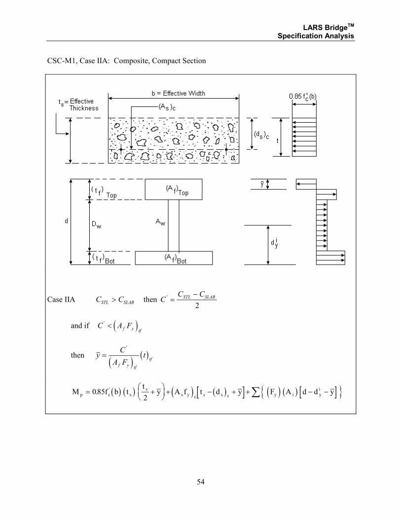
54
CSC-M1, Case IIA: Composite, Compact Section
Case IIA C CSTL SLAB> then CC CSTL SLAB' =
−
2
and if ( )C A Ff y tf
' <
then ( )
( )yC
A Ft
f y tf
tf=
'
( ) ( ) ( ) ( )[ ] ( ) ( ) [ ]{ }M f b tt
y A f t d y F A d d yp c s
s
s y c s s c y i y
i= +
+ − + + − −∑085
2. '
LARS BridgeTM Specification Analysis
55
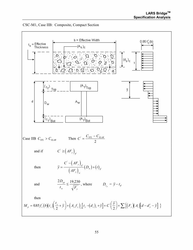
CSC-M1, Case IIB: Composite, Compact Section
Case IIB C CSTL SLAB> Then CC CSTL SLAB' =
−
2
and if ( )C AFy tf
' ≥
then ( )
( )( ) ( )y
C AF
AFD t
y tf
y w
w tf=
−+
'
and 2 19 230D
t F
cp
w y
≤,
, where Dcp = y ttf−
then
( )( ) ( ) ( )[ ] ( ){ ( )[ ] }M f b tt
y A f t d y Cy
F A d d yp c s
s
s y c s s c y i y
i= +
+ − + +
+ − −∑085
2 2. ' '
LARS BridgeTM Specification Analysis
56
Composite, Compact - Moment Capacity
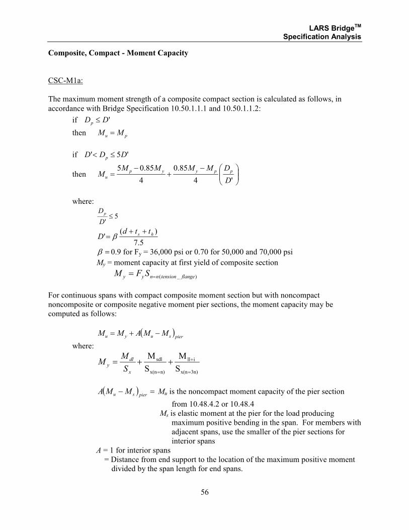
CSC-M1a:
The maximum moment strength of a composite compact section is calculated as follows, in
accordance with Bridge Specification 10.50.1.1.1 and 10.50.1.1.2:
if 'DDp ≤
then pu MM =
if '5' DDD p ≤<
then
−+
−=
'4
85.0
4
85.05
D
DMMMMM
ppyyp
u
where:
5'≤
D
Dp
5.7
)(' hs ttd
D++
= β
=β 0.9 for Fy = 36,000 psi or 0.70 for 50,000 and 70,000 psi
My = moment capacity at first yield of composite section
)_( flangetensionnnyy SFM ==
For continuous spans with compact composite moment section but with noncompact
noncomposite or composite negative moment pier sections, the moment capacity may be
computed as follows:
( )piersuyu MMAMM −+=
where:
S
M
S
M
3n)x(n
ill
n)x(n
sdl
=
+
=
++=x
dly
S
MM
( ) =−piersu MMA Mu is the noncompact moment capacity of the pier section
from 10.48.4.2 or 10.48.4
Ms is elastic moment at the pier for the load producing
maximum positive bending in the span. For members with
adjacent spans, use the smaller of the pier sections for
interior spans
A = 1 for interior spans
= Distance from end support to the location of the maximum positive moment
divided by the span length for end spans.
LARS BridgeTM Specification Analysis
57
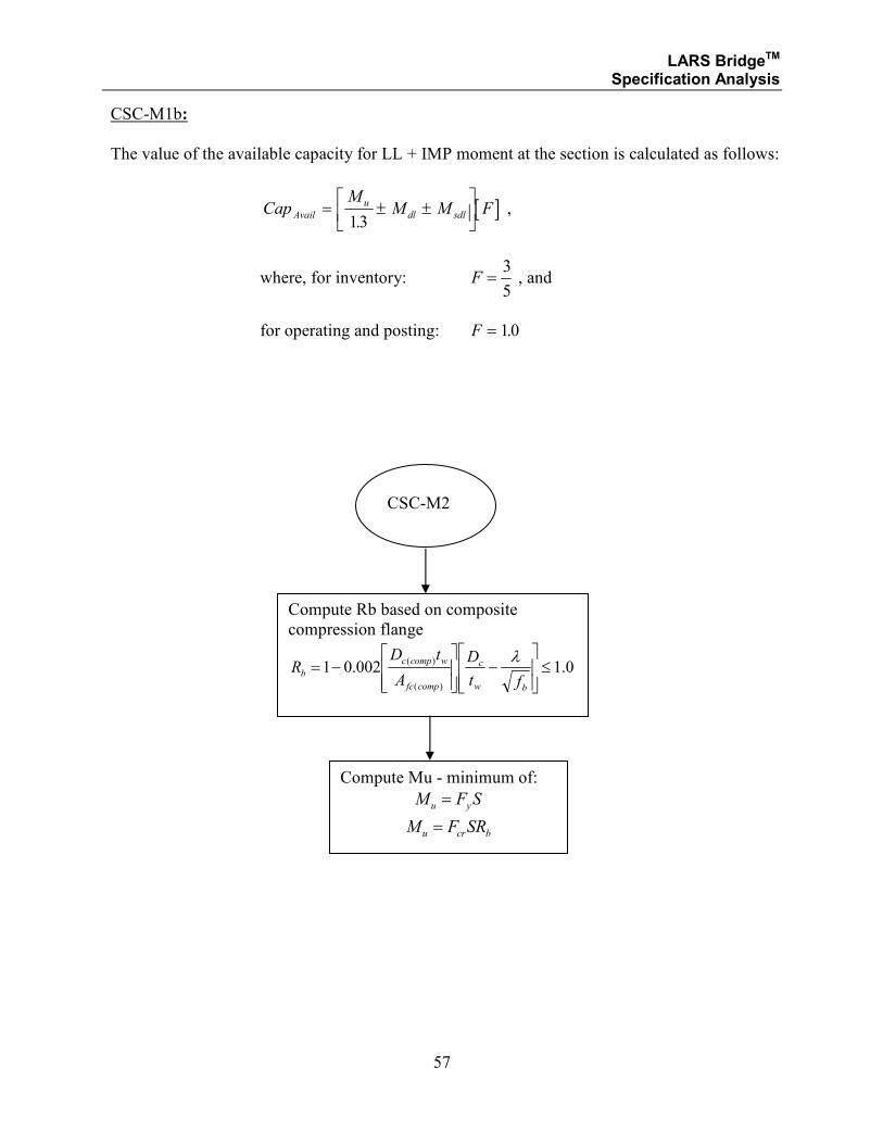
CSC-M1b:
The value of the available capacity for LL + IMP moment at the section is calculated as follows:
[ ]CapM
M M FAvail
u
dl sdl= ± ±
13.
,
where, for inventory: F =3
5 , and
for operating and posting: F = 10.
CSC-M2
Compute Rb based on composite
compression flange
0.1002.01)(
)( ≤
−
−=
bw
c
compfc
wcompc
bft
D
A
tDR
λ
Compute Mu - minimum of:
SFM yu =
bcru SRFM =
LARS BridgeTM Specification Analysis
58
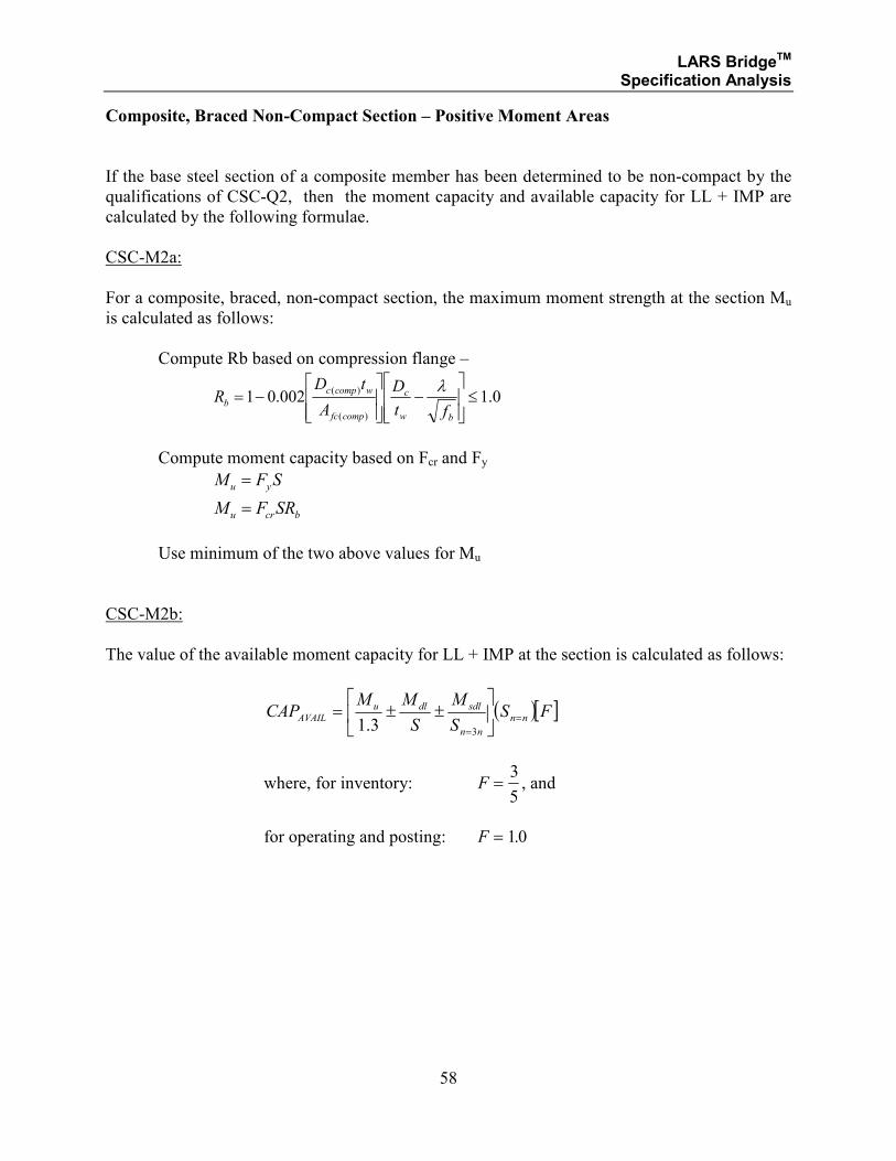
Composite, Braced Non-Compact Section – Positive Moment Areas
If the base steel section of a composite member has been determined to be non-compact by the
qualifications of CSC-Q2, then the moment capacity and available capacity for LL + IMP are
calculated by the following formulae.
CSC-M2a:
For a composite, braced, non-compact section, the maximum moment strength at the section Mu
is calculated as follows:
Compute Rb based on compression flange –
0.1002.01)(
)( ≤
−
−=
bw
c
compfc
wcompc
bft
D
A
tDR
λ
Compute moment capacity based on Fcr and Fy
SFM yu =
bcru SRFM =
Use minimum of the two above values for Mu
CSC-M2b:
The value of the available moment capacity for LL + IMP at the section is calculated as follows:
( )[ ]FSS
M
S
MMCAP nn
nn
sdldluAVAIL =
=
±±=
33.1
where, for inventory: F =3
5, and
for operating and posting: F = 10.
LARS BridgeTM Specification Analysis
59
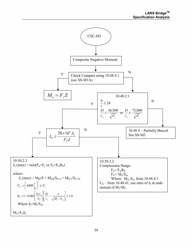
CSC-M3
Composite Negative Moment
Check Compact using 10.48.4.1
(see SS-M1A)
ZFM yu =
Y N
10.48.2.1
24≤t
b
yw Ft
D 500,36≤ or
yw Ft
D 000,73≤
dF
AL
y
f
b
61020×≤
10.50.2.2
fu (max) < min(Fu=Fy or Fu=FcrRb)
where:
fu (max) = Mdl/S + Msdl/Sn=n + Mll+i/Sn=3n
ycr F
b
tF ≤
=2
4400
0.1/
002.01 ≤
−
−=
xcrw
c
fc
wcb
SMt
D
A
tDR
λ
Where fb=Mr/Sxc
Mu=FuSx
10.48.4 – Partially Braced
See SS-M3
10.50.2.2
Compression flange:
Fu= FcrRb
Fu < Mu/Sxc
Where: Mu, Sxc from 10.48.4.1
Cb – from 10.48.41, use ratio of fb at ends
instead of M1/M2
N Y
N Y
LARS BridgeTM Specification Analysis
60
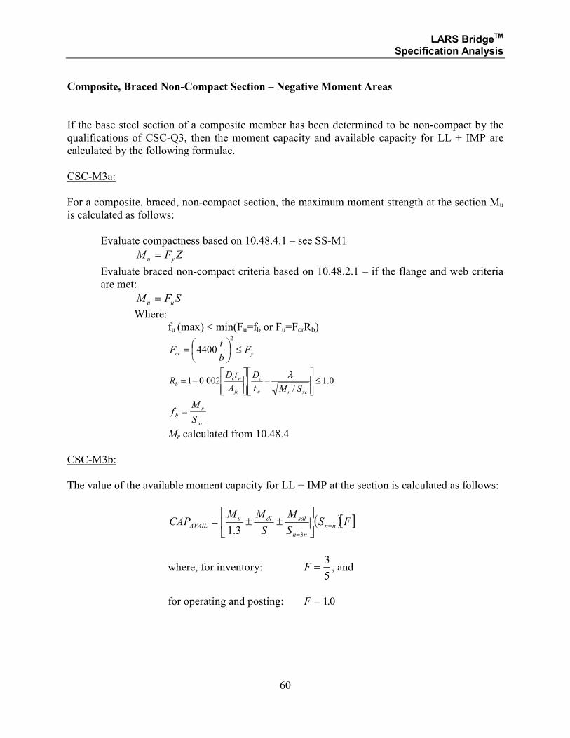
Composite, Braced Non-Compact Section – Negative Moment Areas
If the base steel section of a composite member has been determined to be non-compact by the
qualifications of CSC-Q3, then the moment capacity and available capacity for LL + IMP are
calculated by the following formulae.
CSC-M3a:
For a composite, braced, non-compact section, the maximum moment strength at the section Mu
is calculated as follows:
Evaluate compactness based on 10.48.4.1 – see SS-M1
ZFM yu =
Evaluate braced non-compact criteria based on 10.48.2.1 – if the flange and web criteria
are met:
SFM uu =
Where:
fu (max) < min(Fu=fb or Fu=FcrRb)
ycr F
b
tF ≤
=2
4400
0.1/
002.01 ≤
−
−=
xcrw
c
fc
wcb
SMt
D
A
tDR
λ
xc
r
bS
Mf =
Mr calculated from 10.48.4
CSC-M3b:
The value of the available moment capacity for LL + IMP at the section is calculated as follows:
( )[ ]FSS
M
S
MMCAP nn
nn
sdldluAVAIL =
=
±±=
33.1
where, for inventory: F =3
5, and
for operating and posting: F = 10.
LARS BridgeTM Specification Analysis
61
SECTION 1.2.3
STRUCTURAL STEEL
AND
COMPOSITE STEEL AND CONCRETE
LOAD FACTOR DESIGN METHOD
MOMENT ANALYSIS
FOR:
• HYBRID GIRDERS
LARS BridgeTM Specification Analysis
62
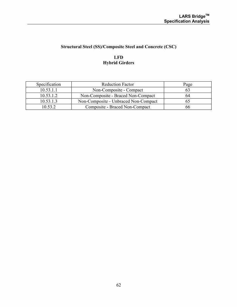
Structural Steel (SS)/Composite Steel and Concrete (CSC)
LFD
Hybrid Girders
Specification Reduction Factor Page
10.53.1.1 Non-Composite - Compact 63
10.53.1.2 Non-Composite - Braced Non-Compact 64
10.53.1.3 Non-Composite - Unbraced Non-Compact 65
10.53.2 Composite - Braced Non-Compact 66
LARS BridgeTM Specification Analysis
63
Structural Steel (SS)/Composite Steel and Concrete (CSC)
LFD
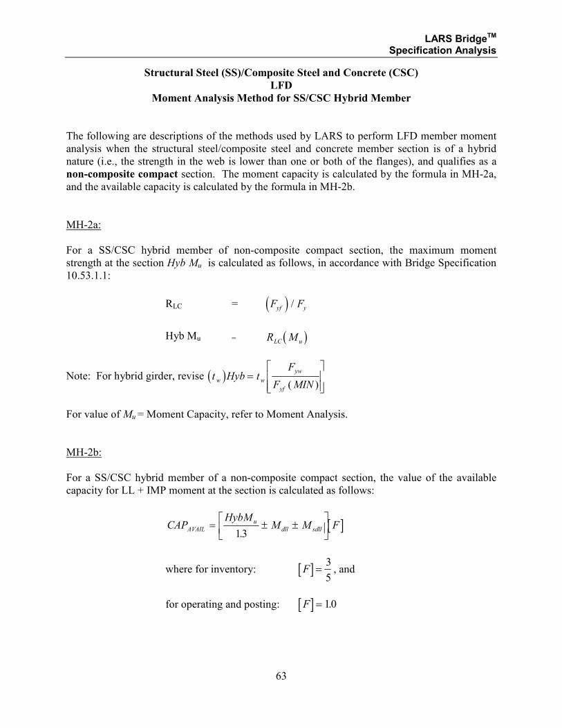
Moment Analysis Method for SS/CSC Hybrid Member
The following are descriptions of the methods used by LARS to perform LFD member moment
analysis when the structural steel/composite steel and concrete member section is of a hybrid
nature (i.e., the strength in the web is lower than one or both of the flanges), and qualifies as a
non-composite compact section. The moment capacity is calculated by the formula in MH-2a,
and the available capacity is calculated by the formula in MH-2b.
MH-2a:
For a SS/CSC hybrid member of non-composite compact section, the maximum moment
strength at the section Hyb Mu is calculated as follows, in accordance with Bridge Specification
10.53.1.1:
RLC = ( )F Fyf y/
Hyb Mu = ( )R MLC u
Note: For hybrid girder, revise ( )t Hyb tF
F MINw w
yw
yf
=
( )
For value of Mu = Moment Capacity, refer to Moment Analysis.
MH-2b:
For a SS/CSC hybrid member of a non-composite compact section, the value of the available
capacity for LL + IMP moment at the section is calculated as follows:
[ ]CAPHybM
M M FAVAIL
u
dll sdll= ± ±
13.
where for inventory: [ ]F =3
5, and
for operating and posting: [ ]F = 10.
LARS BridgeTM Specification Analysis
64
Structural Steel (SS)/Composite Steel and Concrete (CSC)
LFD
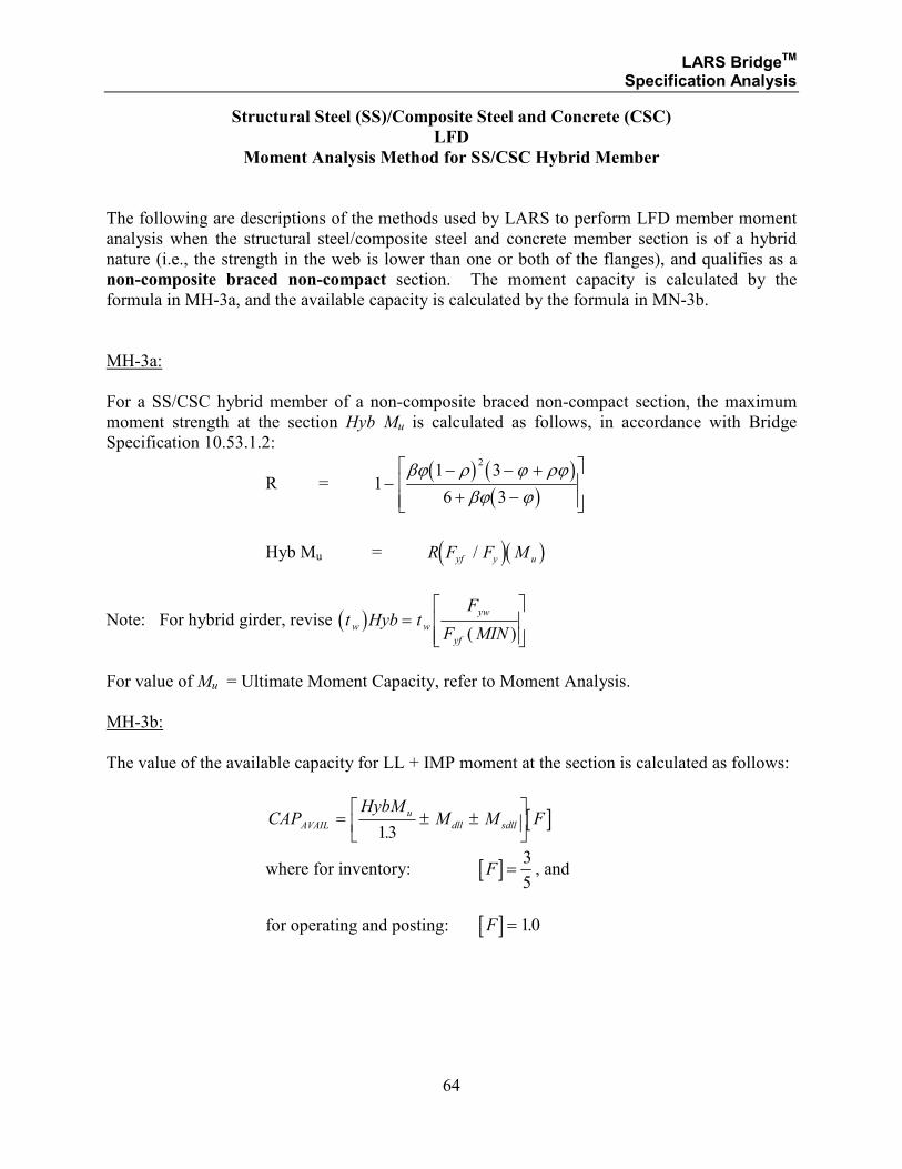
Moment Analysis Method for SS/CSC Hybrid Member
The following are descriptions of the methods used by LARS to perform LFD member moment
analysis when the structural steel/composite steel and concrete member section is of a hybrid
nature (i.e., the strength in the web is lower than one or both of the flanges), and qualifies as a
non-composite braced non-compact section. The moment capacity is calculated by the
formula in MH-3a, and the available capacity is calculated by the formula in MN-3b.
MH-3a:
For a SS/CSC hybrid member of a non-composite braced non-compact section, the maximum
moment strength at the section Hyb Mu is calculated as follows, in accordance with Bridge
Specification 10.53.1.2:
R = ( ) ( )
( )1
1 3
6 3
2
−− − +
+ −
βϕ ρ ϕ ρϕ
βϕ ϕ
Hyb Mu = ( )( )R F F Myf y u/
Note: For hybrid girder, revise ( )t Hyb tF
F MINw w
yw
yf
=
( )
For value of Mu = Ultimate Moment Capacity, refer to Moment Analysis.
MH-3b:
The value of the available capacity for LL + IMP moment at the section is calculated as follows:
[ ]CAPHybM
M M FAVAIL
u
dll sdll= ± ±
13.
where for inventory: [ ]F =3
5, and
for operating and posting: [ ]F = 10.
LARS BridgeTM Specification Analysis
65
Structural Steel (SS)/Composite Steel and Concrete (CSC)
LFD
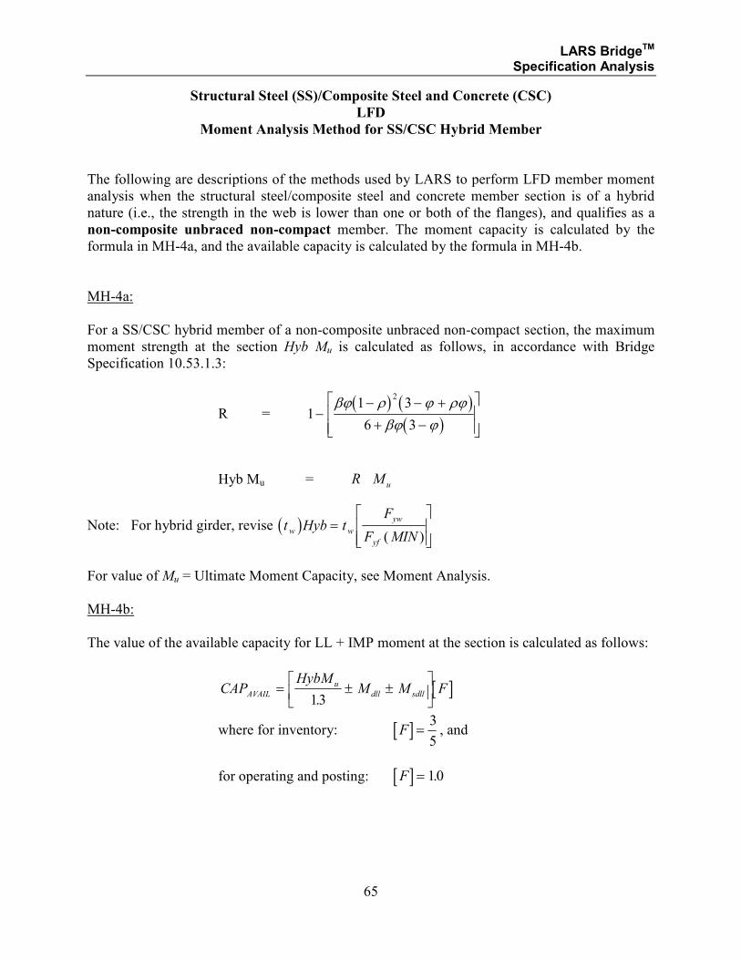
Moment Analysis Method for SS/CSC Hybrid Member
The following are descriptions of the methods used by LARS to perform LFD member moment
analysis when the structural steel/composite steel and concrete member section is of a hybrid
nature (i.e., the strength in the web is lower than one or both of the flanges), and qualifies as a
non-composite unbraced non-compact member. The moment capacity is calculated by the
formula in MH-4a, and the available capacity is calculated by the formula in MH-4b.
MH-4a:
For a SS/CSC hybrid member of a non-composite unbraced non-compact section, the maximum
moment strength at the section Hyb Mu is calculated as follows, in accordance with Bridge
Specification 10.53.1.3:
R = ( ) ( )
( )1
1 3
6 3
2
−− − +
+ −
βϕ ρ ϕ ρϕ
βϕ ϕ
Hyb Mu = R M u
Note: For hybrid girder, revise ( )t Hyb tF
F MINw w
yw
yf
=
( )
For value of Mu = Ultimate Moment Capacity, see Moment Analysis.
MH-4b:
The value of the available capacity for LL + IMP moment at the section is calculated as follows:
[ ]CAPHybM
M M FAVAIL
u
dll sdll= ± ±
13.
where for inventory: [ ]F =3
5, and
for operating and posting: [ ]F = 10.
LARS BridgeTM Specification Analysis
66
Structural Steel (SS)/Composite Steel and Concrete (CSC)
LFD
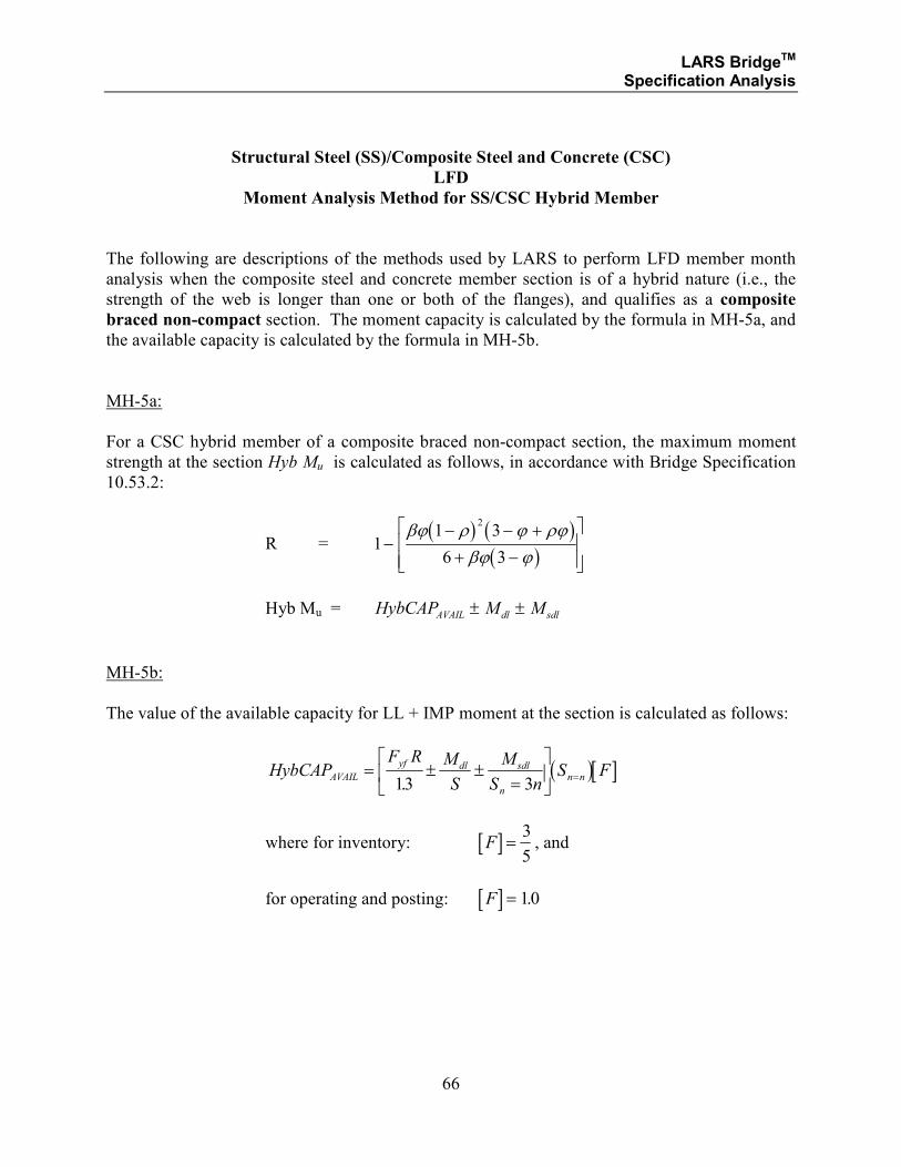
Moment Analysis Method for SS/CSC Hybrid Member
The following are descriptions of the methods used by LARS to perform LFD member month
analysis when the composite steel and concrete member section is of a hybrid nature (i.e., the
strength of the web is longer than one or both of the flanges), and qualifies as a composite
braced non-compact section. The moment capacity is calculated by the formula in MH-5a, and
the available capacity is calculated by the formula in MH-5b.
MH-5a:
For a CSC hybrid member of a composite braced non-compact section, the maximum moment
strength at the section Hyb Mu is calculated as follows, in accordance with Bridge Specification
10.53.2:
R = ( ) ( )
( )1
1 3
6 3
2
−− − +
+ −
βϕ ρ ϕ ρϕ
βϕ ϕ
Hyb Mu = HybCAP M MAVAIL dl sdl± ±
MH-5b:
The value of the available capacity for LL + IMP moment at the section is calculated as follows:
( )[ ]HybCAPF R M
S
M
S nS FAVAIL
yf dl sdl
n
n n= ± ±=
=
13 3.
where for inventory: [ ]F =3
5, and
for operating and posting: [ ]F = 10.
LARS BridgeTM Specification Analysis
67
SECTION 1.2.4
STRUCTURAL STEEL
AND
COMPOSITE STEEL AND CONCRETE
LOAD FACTOR DESIGN METHOD
SHEAR ANALYSIS
LARS BridgeTM Specification Analysis
68
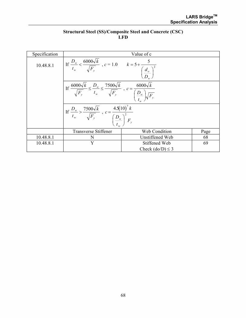
Structural Steel (SS)/Composite Steel and Concrete (CSC)
LFD
Specification Value of c
10.48.8.1 If D
t
k
F
w
w y
<6000
, c = 1.0 kd
D
o
w
= +
55
2
If
6000 7500k
F
D
t
k
Fy
w
w y
≤ ≤ , ck
D
tFw
w
y
=
6000
If
D
t
k
F
w
w y
>7500
, ( )
ck
D
tFw
w
y
=
4 5 107
2
.
Transverse Stiffener Web Condition Page
10.48.8.1 N Unstiffened Web 68
10.48.8.1 Y Stiffened Web
Check (do/D) ≤ 3 69
LARS BridgeTM Specification Analysis
69
Structural Steel (SS)/Composite Steel and Concrete (CSC)
LFD
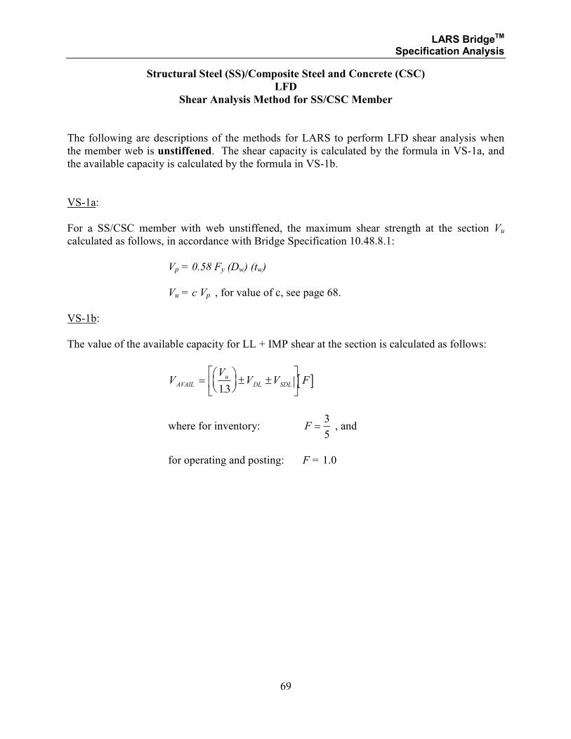
Shear Analysis Method for SS/CSC Member
The following are descriptions of the methods for LARS to perform LFD shear analysis when
the member web is unstiffened. The shear capacity is calculated by the formula in VS-1a, and
the available capacity is calculated by the formula in VS-1b.
VS-1a:
For a SS/CSC member with web unstiffened, the maximum shear strength at the section Vu
calculated as follows, in accordance with Bridge Specification 10.48.8.1:
Vp = 0.58 Fy (Dw) (tw)
Vu = c Vp , for value of c, see page 68.
VS-1b:
The value of the available capacity for LL + IMP shear at the section is calculated as follows:
[ ]VV
V V FAVAIL
u
DL SDL=
± ±
13.
where for inventory: F =3
5 , and
for operating and posting: F = 1.0
LARS BridgeTM Specification Analysis
70
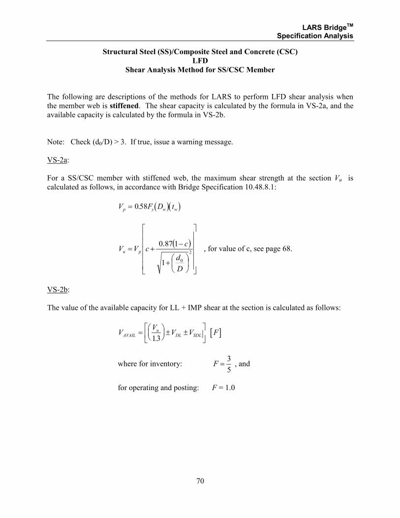
Structural Steel (SS)/Composite Steel and Concrete (CSC)
LFD
Shear Analysis Method for SS/CSC Member
The following are descriptions of the methods for LARS to perform LFD shear analysis when
the member web is stiffened. The shear capacity is calculated by the formula in VS-2a, and the
available capacity is calculated by the formula in VS-2b.
Note: Check (d0/D) > 3. If true, issue a warning message.
VS-2a:
For a SS/CSC member with stiffened web, the maximum shear strength at the section Vu is
calculated as follows, in accordance with Bridge Specification 10.48.8.1:
( )( )V F D tp y w w= 058.
( )
+
−+=
2
01
187.0
D
d
ccVV pu , for value of c, see page 68.
VS-2b:
The value of the available capacity for LL + IMP shear at the section is calculated as follows:
[ ]VV
V V FAVAILu
DL SDL=
± ±
13.
where for inventory: F =3
5 , and
for operating and posting: F = 1.0
LARS BridgeTM Specification Analysis
71
SECTION 1.2.5
STRUCTURAL STEEL
AND
COMPOSITE STEEL AND CONCRETE
LOAD FACTOR DESIGN METHOD
FOR
MOMENT - SHEAR INTERACTION
LARS BridgeTM Specification Analysis
72
Structural Steel (SS)/Composite Steel and Concrete (CSC)
LFD
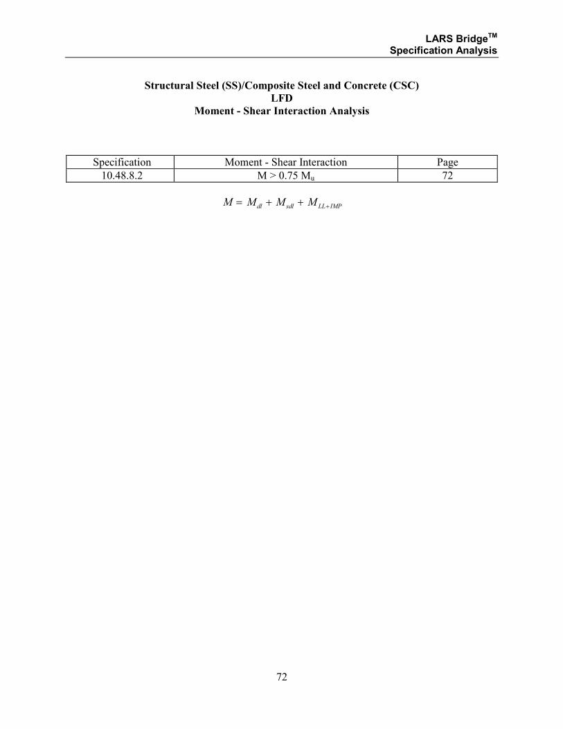
Moment - Shear Interaction Analysis
Specification Moment - Shear Interaction Page
10.48.8.2 M > 0.75 Mu 72
M M M Mdl sdl LL IMP= + + +
LARS BridgeTM Specification Analysis
73
Structural Steel (SS)/Composite Steel and Concrete (CSC)
LFD
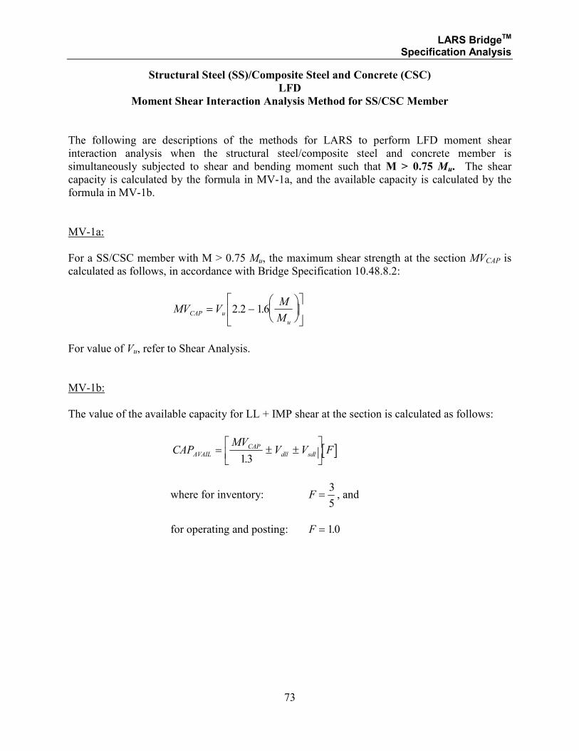
Moment Shear Interaction Analysis Method for SS/CSC Member
The following are descriptions of the methods for LARS to perform LFD moment shear
interaction analysis when the structural steel/composite steel and concrete member is
simultaneously subjected to shear and bending moment such that M > 0.75 Mu. The shear
capacity is calculated by the formula in MV-1a, and the available capacity is calculated by the
formula in MV-1b.
MV-1a:
For a SS/CSC member with M > 0.75 Mu, the maximum shear strength at the section MVCAP is
calculated as follows, in accordance with Bridge Specification 10.48.8.2:
MV VM
MCAP u
u
= −
2 2 16. .
For value of Vu, refer to Shear Analysis.
MV-1b:
The value of the available capacity for LL + IMP shear at the section is calculated as follows:
[ ]CAPMV
V V FAVAIL
CAP
dll sdl= ± ±
13.
where for inventory: F =3
5, and
for operating and posting: F = 10.

LARS BridgeTM Specification Analysis
74
SECTION 1.2.6
STRUCTURAL STEEL
AND
COMPOSITE STEEL AND CONCRETE
LOAD FACTOR DESIGN METHODS
FOR
STIFFENER REQUIREMENTS
LARS BridgeTM Specification Analysis
75
Structural Steel (SS)/Composite Steel and Concrete (CSC)
LFD
Stiffener Requirement
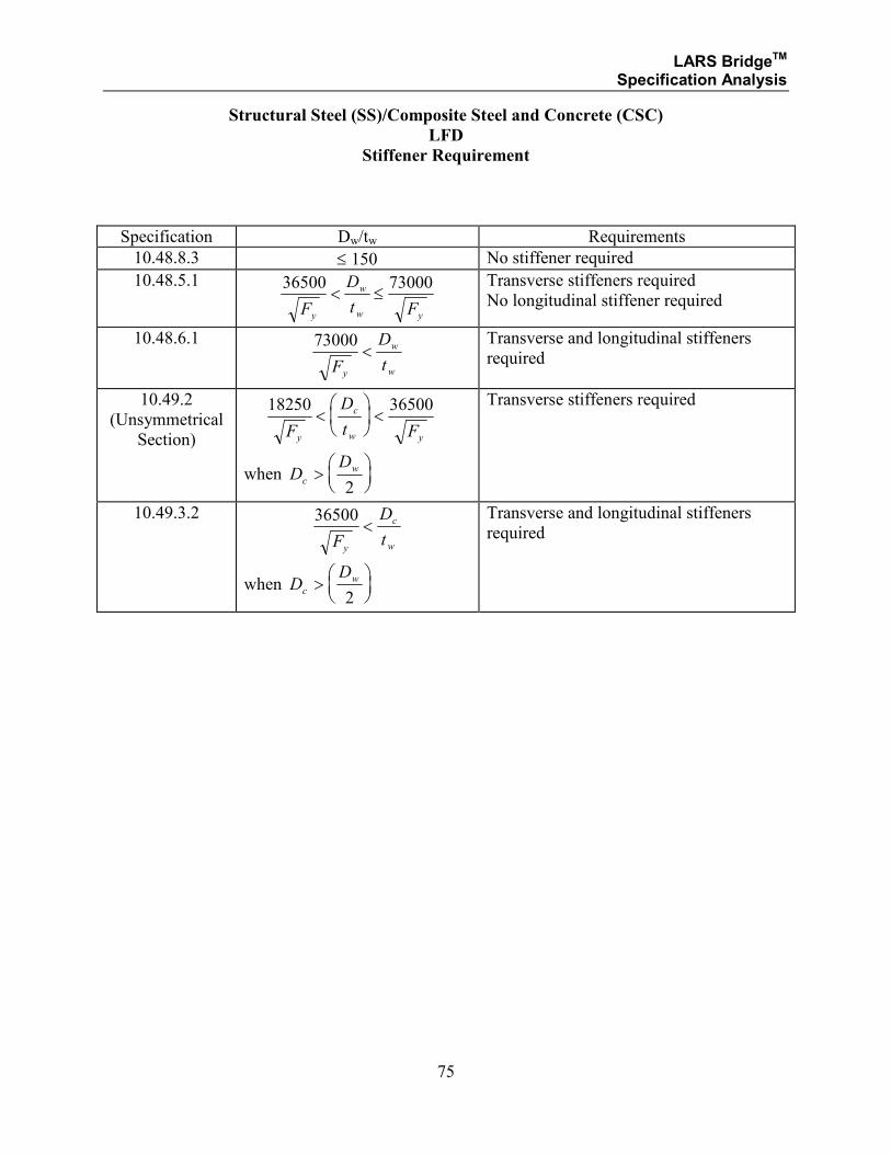
Specification Dw/tw Requirements
10.48.8.3 ≤ 150 No stiffener required
10.48.5.1 36500 73000
F
D
t Fy
w
w y
< ≤ Transverse stiffeners required
No longitudinal stiffener required
10.48.6.1
73000
F
D
ty
w
w
< Transverse and longitudinal stiffeners
required
10.49.2
(Unsymmetrical
Section)
18250 36500
F
D
t Fy
c
w y
<
<
when DD
c
w>
2
Transverse stiffeners required
10.49.3.2 36500
F
D
ty
c
w
<
when DD
c
w>
2
Transverse and longitudinal stiffeners
required
LARS BridgeTM Specification Analysis
76
SECTION 1.2.7
STRUCTURAL STEEL
AND
COMPOSITE STEEL AND CONCRETE
LOAD FACTOR DESIGN METHOD
FOR
SERVICEABILITY MOMENT ANALYSIS

LARS BridgeTM Specification Analysis
77
Structural Steel (SS)/Composite Steel and Concrete (CSC)
LFD
Serviceability Moment Analysis
Specification Member Page
10.57.1* Non-Composite Structural Steel (SS) 77
10.57.2* Composite Steel and Concrete (CSC) 78
* Also see Manual for Condition Evaluation of Bridges, 6.6.3.1.
LARS BridgeTM Specification Analysis
78
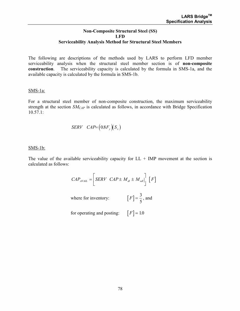
Non-Composite Structural Steel (SS)
LFD
Serviceability Analysis Method for Structural Steel Members
The following are descriptions of the methods used by LARS to perform LFD member
serviceability analysis when the structural steel member section is of non-composite
construction. The serviceability capacity is calculated by the formula in SMS-1a, and the
available capacity is calculated by the formula in SMS-1b.
SMS-1a:
For a structural steel member of non-composite construction, the maximum serviceability
strength at the section SMCAP is calculated as follows, in accordance with Bridge Specification
10.57.1:
( )( )SERV CAP F Sy x= 08.
SMS-1b:
The value of the available serviceability capacity for LL + IMP movement at the section is
calculated as follows:
[ ]CAP SERV CAP M M FAVAIL dl sdl= ± ±
where for inventory: [ ]F =3
5, and
for operating and posting: [ ]F = 10.
LARS BridgeTM Specification Analysis
79
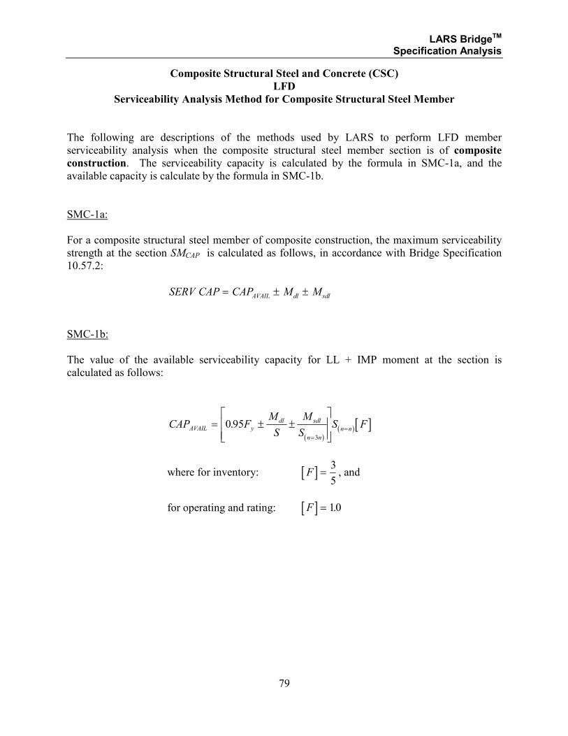
Composite Structural Steel and Concrete (CSC)
LFD
Serviceability Analysis Method for Composite Structural Steel Member
The following are descriptions of the methods used by LARS to perform LFD member
serviceability analysis when the composite structural steel member section is of composite
construction. The serviceability capacity is calculated by the formula in SMC-1a, and the
available capacity is calculate by the formula in SMC-1b.
SMC-1a:
For a composite structural steel member of composite construction, the maximum serviceability
strength at the section SMCAP is calculated as follows, in accordance with Bridge Specification
10.57.2:
SERV CAP CAP M MAVAIL dl sdl= ± ±
SMC-1b:
The value of the available serviceability capacity for LL + IMP moment at the section is
calculated as follows:
( )
( ) [ ]CAP FM
S
M
SS FAVAIL y
dl sdl
n n
n n= ± ±
=
=0 953
.
where for inventory: [ ]F =3
5, and
for operating and rating: [ ]F = 10.
LARS BridgeTM Specification Analysis
80
SECTION 1.3.2
COMPOSITE STRUCTURAL STEEL AND CONCRETE
LOAD RESISTANCE FACTOR DESIGN METHODS
STRENGTH LIMIT STATE ANALYSIS
FOR:
• COMPOSITE COMPACT SECTIONS
• NONCOMPACT SECTIONS
LARS BridgeTM Specification Analysis
81
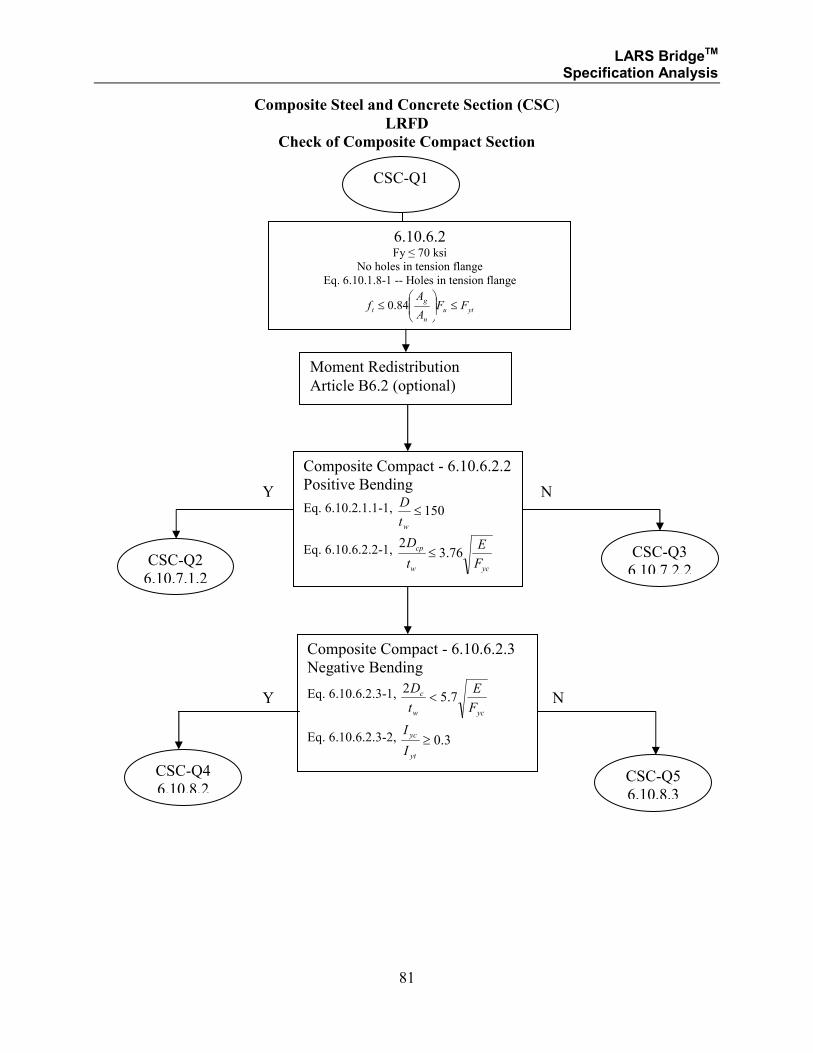
Composite Steel and Concrete Section (CSC)
LRFD
Check of Composite Compact Section
6.10.6.2 Fy ≤ 70 ksi
No holes in tension flange
Eq. 6.10.1.8-1 -- Holes in tension flange
ytu
n
g
t FFA
Af ≤
≤ 84.0
CSC-Q1
Composite Compact - 6.10.6.2.2
Positive Bending
Eq. 6.10.2.1.1-1, 150≤wt
D
Eq. 6.10.6.2.2-1,
ycw
cp
F
E
t
D76.3
2≤
N Y
Composite Compact - 6.10.6.2.3
Negative Bending
Eq. 6.10.6.2.3-1,
ycw
c
F
E
t
D7.5
2<
Eq. 6.10.6.2.3-2, 3.0≥yt
yc
I
I
CSC-Q2
6.10.7.1.2
CSC-Q3
6.10.7.2.2
CSC-Q4
6.10.8.2 CSC-Q5
6.10.8.3
N Y
Moment Redistribution
Article B6.2 (optional)
LARS BridgeTM Specification Analysis
82
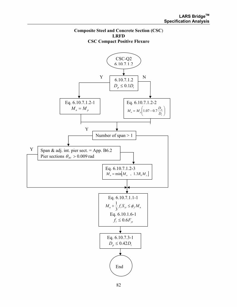
Composite Steel and Concrete Section (CSC)
LRFD
CSC Compact Positive Flexure
6.10.7.1.2
tp DD 1.0≤
Eq. 6.10.7.1.2-1
pn MM =
Eq. 6.10.7.1.2-2
−=
t
p
pnD
DMM 7.007.1
CSC-Q2
6.10.7.1.2
Eq. 6.10.7.1.2-3 [ ]yhnn MRMM 3.1,min=
Eq. 6.10.7.3-1
tp DD 42.0≤
Y N
Number of span > 1
Y
Span & adj. int. pier sect. = App. B6.2
Pier sections 009.0>RLθ rad
Eq. 6.10.7.1.1-1
nfxtru MSfM φ≤+3
1
Eq. 6.10.1.6-1
ytFf 6.0≤l
End
Y
LARS BridgeTM Specification Analysis
83
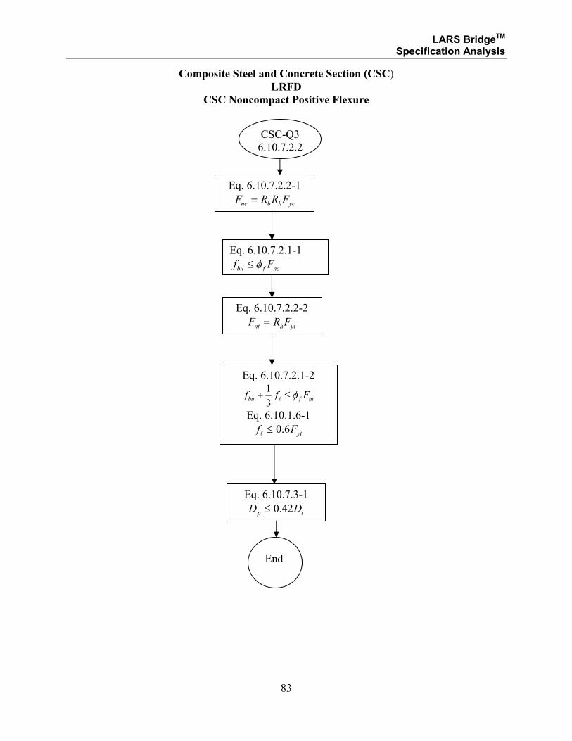
Composite Steel and Concrete Section (CSC)
LRFD
CSC Noncompact Positive Flexure
Eq. 6.10.7.2.2-1
ychbnc FRRF =
CSC-Q3
6.10.7.2.2
Eq. 6.10.7.3-1
tp DD 42.0≤
Eq. 6.10.7.2.1-2
ntfbu Fff φ≤+l
3
1
Eq. 6.10.1.6-1
ytFf 6.0≤l
End
Eq. 6.10.7.2.1-1
ncfbu Ff φ≤
Eq. 6.10.7.2.2-2
ythnt FRF =
LARS BridgeTM Specification Analysis
84
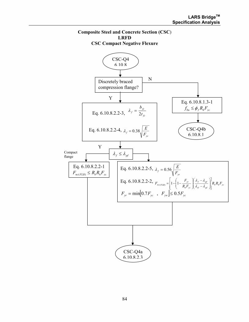
Composite Steel and Concrete Section (CSC)
LRFD
CSC Compact Negative Flexure
CSC-Q4
6.10.8
Y
Discretely braced
compression flange?
N
Y
Eq. 6.10.8.2.2-3, fc
fc
ft
b
2=λ
Eq. 6.10.8.2.2-4, yc
fF
E38.0=λ
pff λλ ≤
Eq. 6.10.8.2.2-1
ychbFLBnc FRRF ≤)(
CSC-Q4b
6.10.8.1
Compact
flange
Eq. 6.10.8.2.2-5, yr
fF
E56.0=λ
Eq. 6.10.8.2.2-2, ychb
pfrf
pff
ych
yr
FLBnc FRRFR
FF
−
−
−−=
λλ
λλ11
)(
[ ] ycywycyr FFFF 5.0,7.0min ≤=
CSC-Q4a
6.10.8.2.3
Eq. 6.10.8.1.3-1
ychfbu FRf φ≤
LARS BridgeTM Specification Analysis
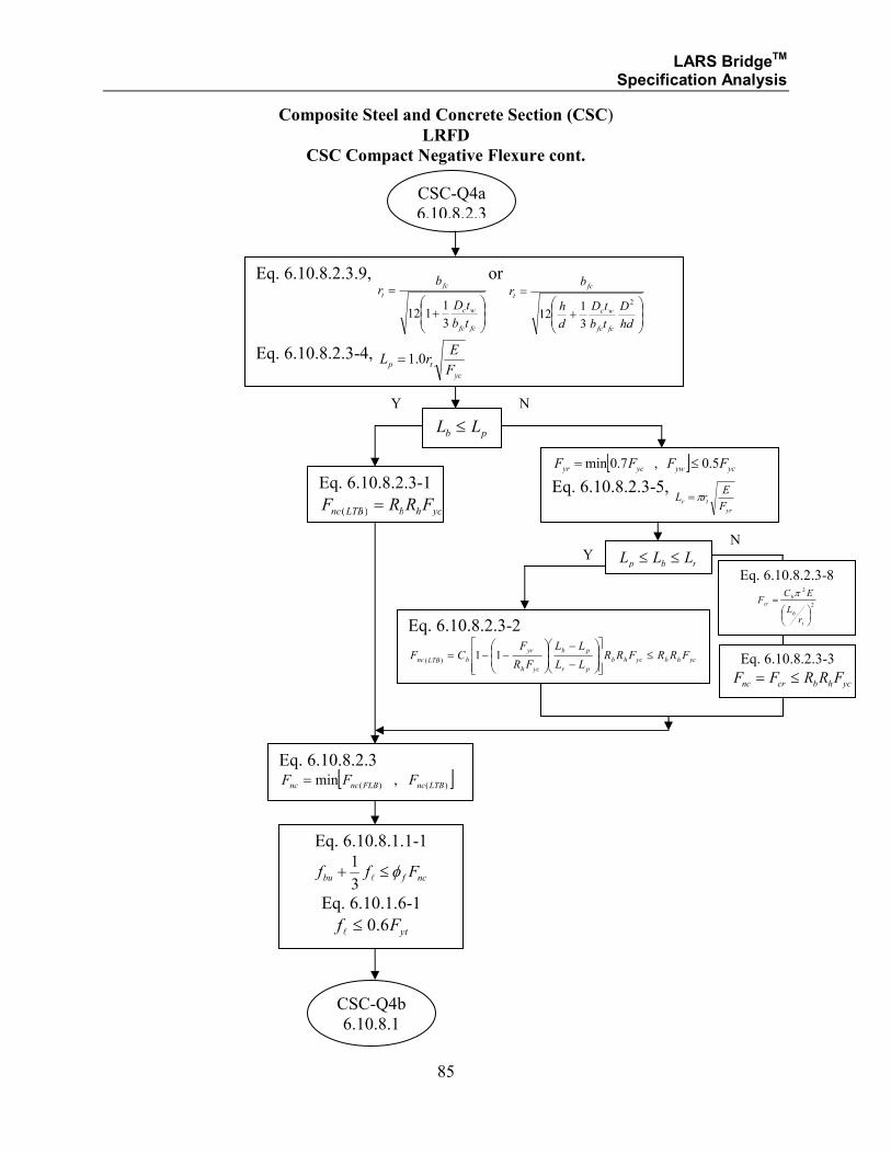
85
Composite Steel and Concrete Section (CSC)
LRFD
CSC Compact Negative Flexure cont.
Eq. 6.10.8.2.3.9,
+
=
fcfc
wc
fc
t
tb
tD
br
3
1112
or
+
=
hd
D
tb
tD
d
h
br
fcfc
wc
fc
t2
3
112
Eq. 6.10.8.2.3-4, yc
tpF
ErL 0.1=
CSC-Q4a
6.10.8.2.3
pb LL ≤
Y N
Eq. 6.10.8.2.3-1
ychbLTBnc FRRF =)(
Eq. 6.10.8.2.3 [ ])()( ,min LTBncFLBncnc FFF =
Eq. 6.10.8.1.1-1
ncfbu Fff φ≤+l
3
1
Eq. 6.10.1.6-1
ytFf 6.0≤l
[ ] ycywycyr FFFF 5.0,7.0min ≤=
Eq. 6.10.8.2.3-5,
yr
trF
ErL π=
rbp LLL ≤≤ Y N
Eq. 6.10.8.2.3-2
ychbychb
pr
pb
ych
yr
bLTBnc FRRFRRLL
LL
FR
FCF ≤
−
−
−−= 11
)(
Eq. 6.10.8.2.3-3
ychbcrnc FRRFF ≤=
CSC-Q4b
6.10.8.1
Eq. 6.10.8.2.3-8
2
2
=
t
b
b
cr
rL
ECF
π

LARS BridgeTM Specification Analysis
86
Composite Steel and Concrete Section (CSC)
LRFD
CSC Compact Negative Flexure cont.
Discretely braced
tension flange?
Y N
Eq. 6.10.8.1.3-1
ythfbu FRf φ≤
Eq. 6.10.8.3-1
ythnt FRF =
Eq. 6.10.8.1.2-1
ntfbu Fff φ≤+l
3
1
Eq. 6.10.1.6-1
ytFf 6.0≤l
End
CSC-Q4b
6.10.8.1

LARS BridgeTM Specification Analysis
87
Note: The area of the slab steel is included in the resisting capacity of the steel or
composite section when the steel is defined on input (i.e., RT 14), the CP is in the
negative moment area (i.e., within 0.3 of the span length either side of the interior
supports of continuous members, and then only for positive bending analysis).
LARS BridgeTM Specification Analysis
88
Eq. A6.2.2-4,
yc
p
yc
p
Dpwrw
Dpww
p
ych
pcM
M
M
M
M
MRR
c
c ≤
−
−
−−=
)(
)(11
λλ
λλ
Eq. A6.2.2-5,
yt
p
yt
p
Dpwrw
Dpww
p
yth
ptM
M
M
M
M
MRR
c
c ≤
−
−
−−=
)(
)(11
λλ
λλ
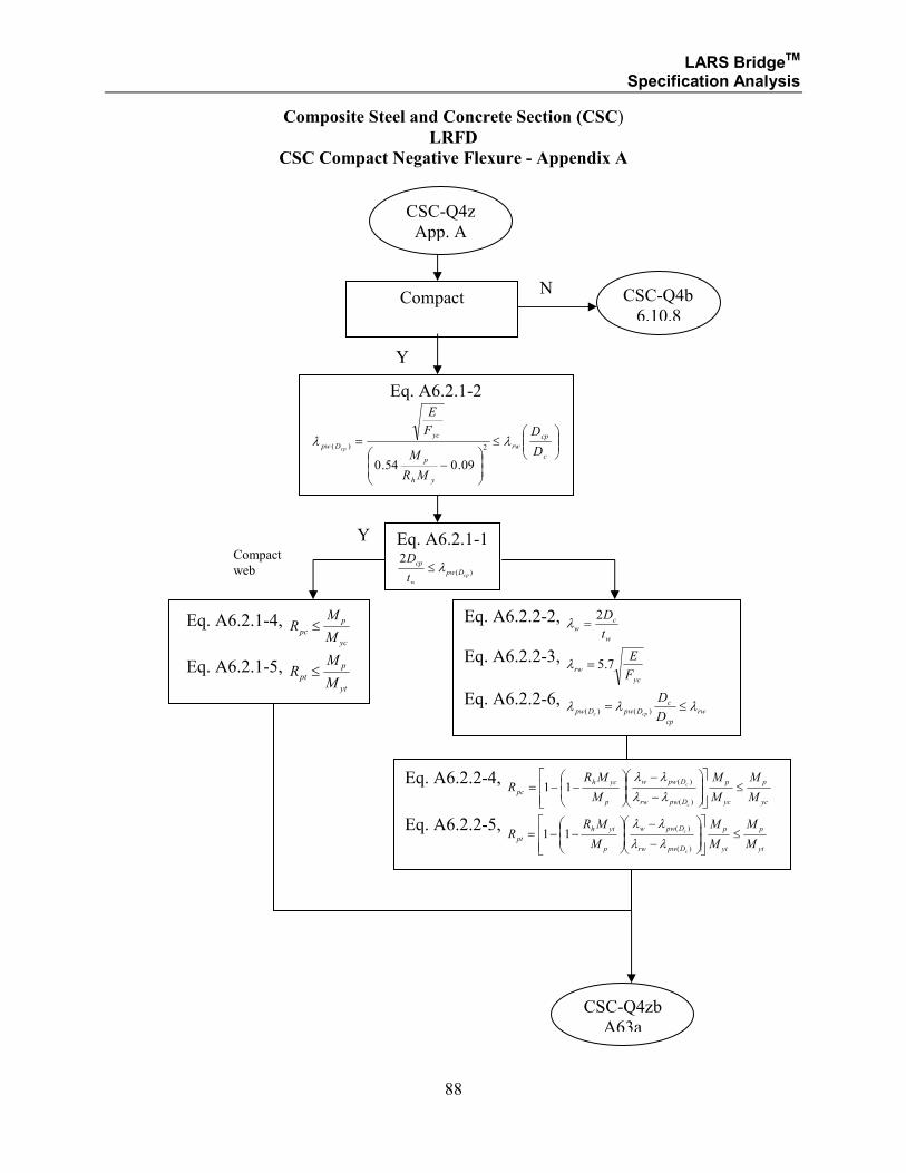
Composite Steel and Concrete Section (CSC)
LRFD
CSC Compact Negative Flexure - Appendix A
CSC-Q4z
App. A
Y
Compact N
Y
Eq. A6.2.1-2
≤
−
=c
cp
rw
yh
p
yc
DpwD
D
MR
M
F
E
cpλλ
2)(
09.054.0
Eq. A6.2.1-1
)(
2
cpDpw
w
cp
t
Dλ≤
Eq. A6.2.1-4, yc
p
pcM
MR ≤
Eq. A6.2.1-5, yt
p
ptM
MR ≤
CSC-Q4b
6.10.8
Compact
web
Eq. A6.2.2-2, w
cw
t
D2=λ
Eq. A6.2.2-3, yc
rwF
E7.5=λ
Eq. A6.2.2-6, rw
cp
cDpwDpw
D
Dcpc
λλλ ≤= )()(
CSC-Q4zb
A63a
LARS BridgeTM Specification Analysis
89
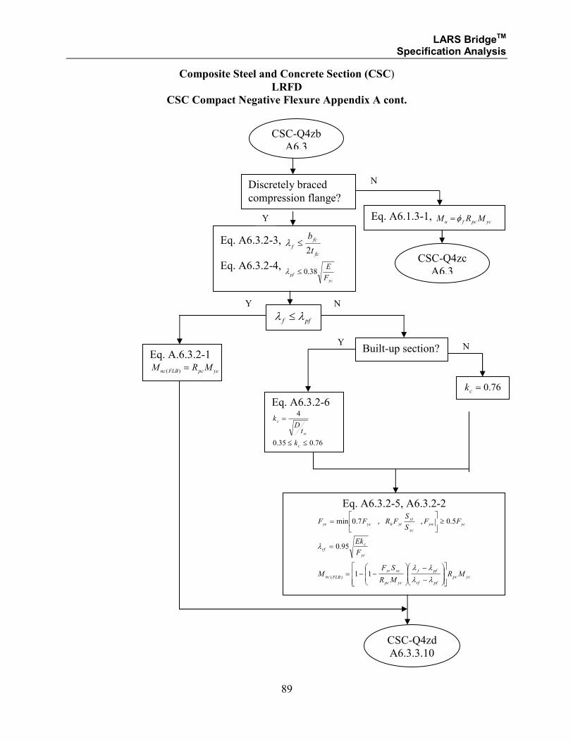
Composite Steel and Concrete Section (CSC)
LRFD
CSC Compact Negative Flexure Appendix A cont.
Discretely braced
compression flange?
CSC-Q4zb
A6.3
Eq. A6.3.2-3, fc
fc
ft
b
2≤λ
Eq. A6.3.2-4,
yc
pfF
E38.0≤λ
Y
N
pff λλ ≤
Eq. A.6.3.2-1
ycpcFLBnc MRM =)(
Eq. A6.3.2-5, A6.3.2-2
ycpc
pfrf
pff
ycpc
xcyr
FLBnc
yr
c
rf
ycyw
xc
xt
ythycyr
MRMR
SFM
F
Ek
FFS
SFRFF
−
−
−−=
=
≥
=
λλ
λλ
λ
11
95.0
5.0,,7.0min
)(
Eq. A6.1.3-1, ycpcfu MRM φ=
Y N
Eq. A6.3.2-6
76.035.0
4
≤≤
=
c
w
c
k
tD
k
76.0=ck
CSC-Q4zd
A6.3.3.10
CSC-Q4zc
A6.3
Y N
Built-up section?
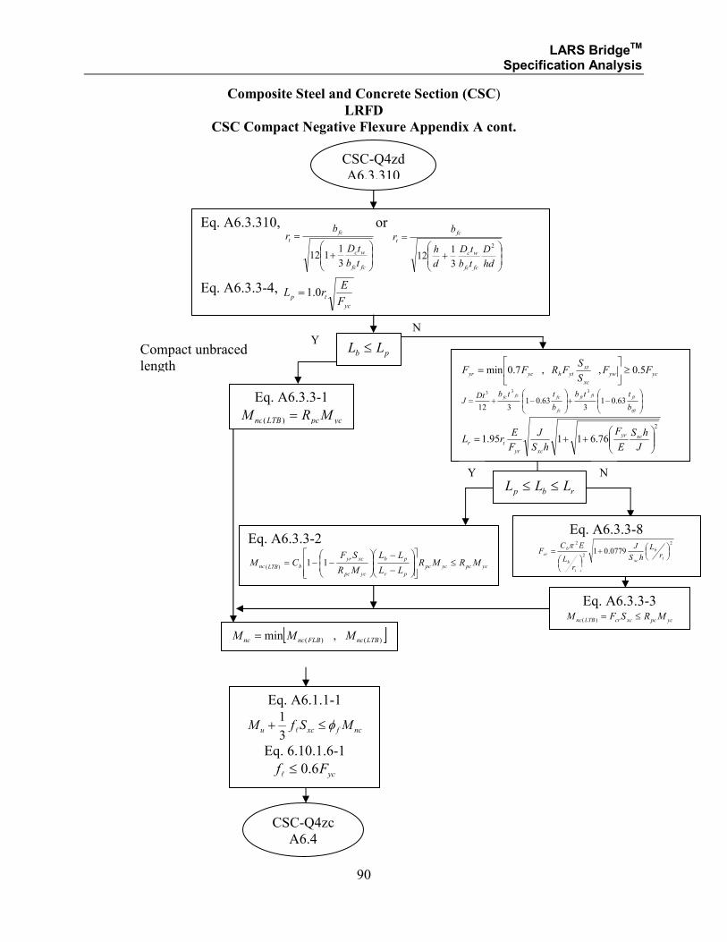
LARS BridgeTM Specification Analysis
90
Composite Steel and Concrete Section (CSC)
LRFD
CSC Compact Negative Flexure Appendix A cont.
CSC-Q4zd
A6.3.310
Eq. A6.3.310,
+
=
fcfc
wc
fc
t
tb
tD
br
3
1112
or
+
=
hd
D
tb
tD
d
h
br
fcfc
wc
fc
t2
3
112
Eq. A6.3.3-4, yc
tpF
ErL 0.1=
pb LL ≤ Y
N
Eq. A6.3.3-1
ycpcLTBnc MRM =)(
[ ])()( ,min LTBncFLBncnc MMM =
Eq. A6.1.1-1
ncfxcu MSfM φ≤+l
3
1
Eq. 6.10.1.6-1
ycFf 6.0≤l
ycyw
xc
xtythycyr FFS
SFRFF 5.0,,7.0min ≥
=
−+
−+=
tft
ftftft
fc
fcfcfc
b
ttb
b
ttbDtJ 63.01
363.01
312
333
2
76.61195.1
++=
J
hS
E
F
hS
J
F
ErL xcyr
xcyr
tr
rbp LLL ≤≤ Y N
Eq. A6.3.3-2
ycpcycpc
pr
pb
ycpc
xcyr
bLTBnc MRMRLL
LL
MR
SFCM ≤
−
−
−−= 11
)(
Eq. A6.3.3-3
ycpcxccrLTBnc MRSFM ≤=)(
CSC-Q4zc
A6.4
Compact unbraced
length
Eq. A6.3.3-8 2
2
2
0779.01
+
=t
b
xc
t
b
b
cr rL
hS
J
rL
ECF
π
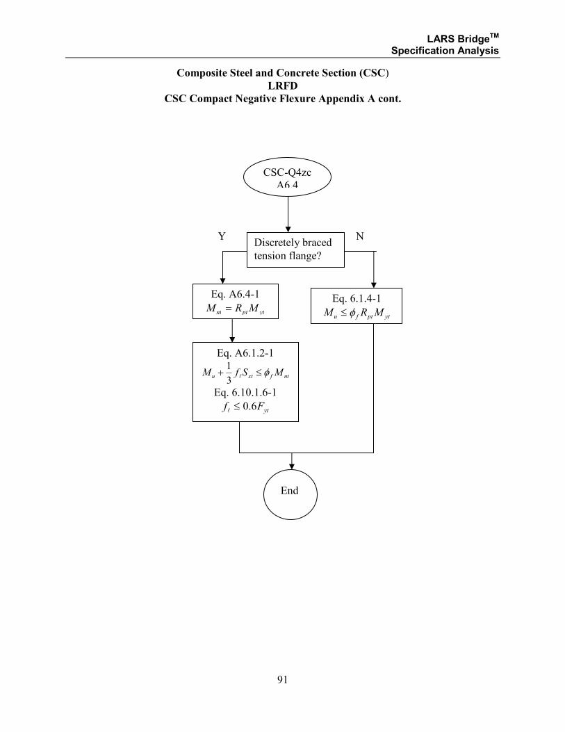
LARS BridgeTM Specification Analysis
91
Composite Steel and Concrete Section (CSC)
LRFD
CSC Compact Negative Flexure Appendix A cont.
Discretely braced
tension flange?
Y N
Eq. 6.1.4-1
ytptfu MRM φ≤
Eq. A6.4-1
ytptnt MRM =
Eq. A6.1.2-1
ntfxtu MSfM φ≤+l
3
1
Eq. 6.10.1.6-1
ytFf 6.0≤l
End
CSC-Q4zc
A6.4
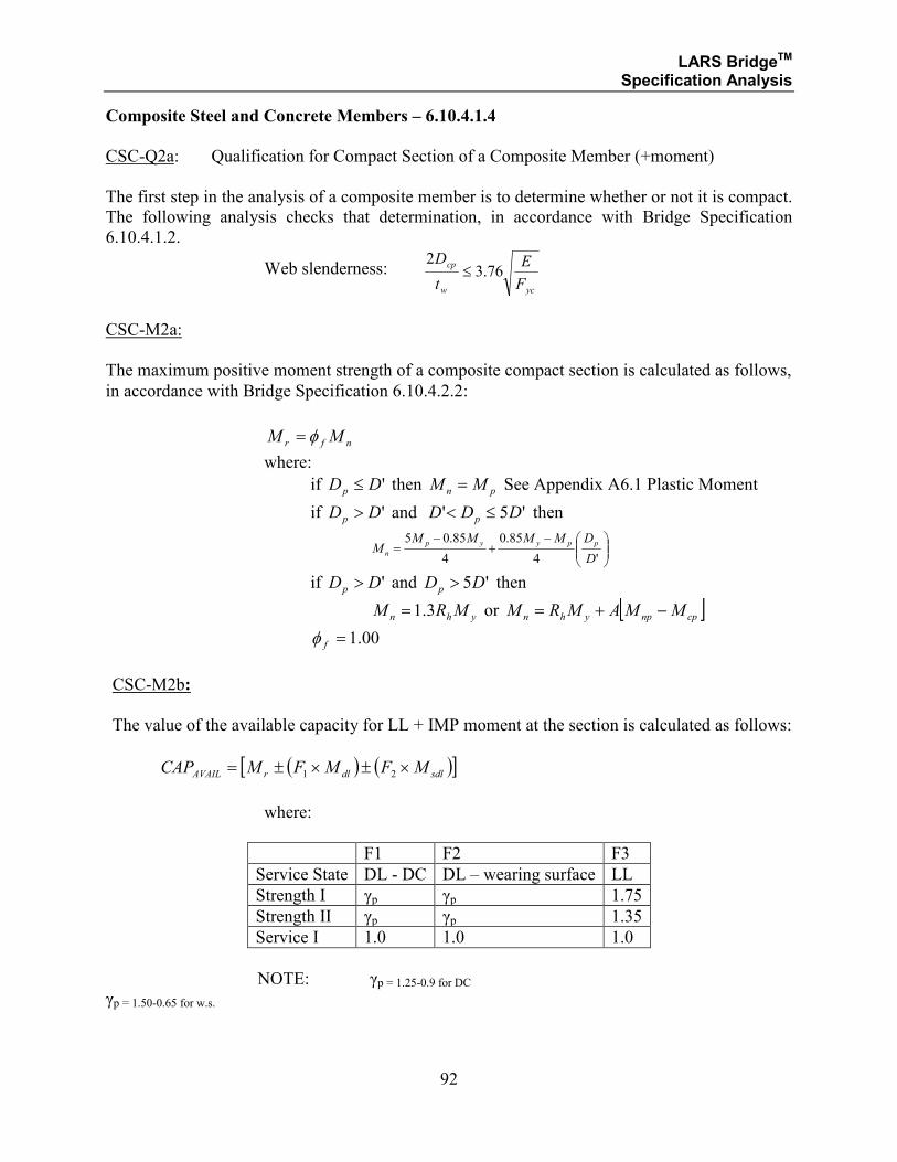
LARS BridgeTM Specification Analysis
92
Composite Steel and Concrete Members – 6.10.4.1.4
CSC-Q2a: Qualification for Compact Section of a Composite Member (+moment)
The first step in the analysis of a composite member is to determine whether or not it is compact.
The following analysis checks that determination, in accordance with Bridge Specification
6.10.4.1.2.
Web slenderness: ycw
cp
F
E
t
D76.3
2≤
CSC-M2a:
The maximum positive moment strength of a composite compact section is calculated as follows,
in accordance with Bridge Specification 6.10.4.2.2:
nfr MM φ=
where:
if 'DDp ≤ then pn MM = See Appendix A6.1 Plastic Moment
if 'DDp > and '5' DDD p ≤< then
−+
−=
'4
85.0
4
85.05
D
DMMMMM
ppyyp
n
if 'DDp > and '5DDp > then
yhn MRM 3.1= or [ ]cpnpyhn MMAMRM −+=
00.1=fφ
CSC-M2b:
The value of the available capacity for LL + IMP moment at the section is calculated as follows:
( ) ( )[ ]sdldlrAVAIL MFMFMCAP ×±×±= 21
where:
F1 F2 F3
Service State DL - DC DL – wearing surface LL
Strength I γp γp 1.75
Strength II γp γp 1.35
Service I 1.0 1.0 1.0
NOTE: γp = 1.25-0.9 for DC γp = 1.50-0.65 for w.s.
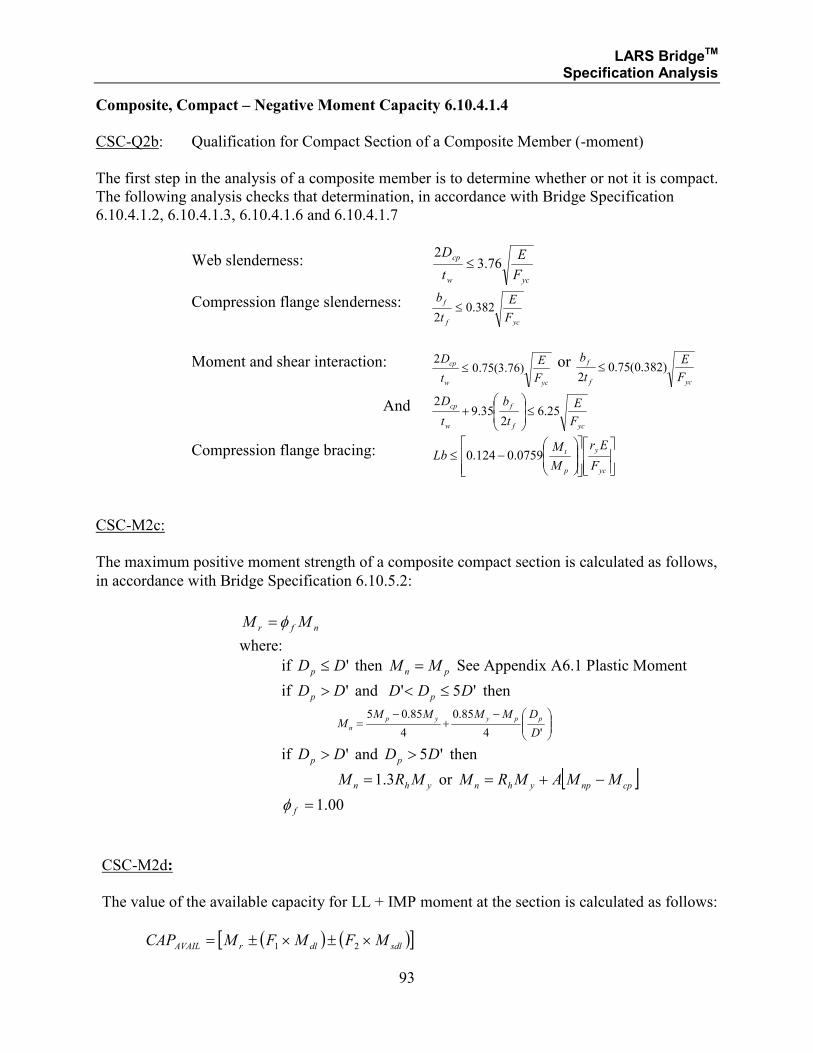
LARS BridgeTM Specification Analysis
93
Composite, Compact – Negative Moment Capacity 6.10.4.1.4
CSC-Q2b: Qualification for Compact Section of a Composite Member (-moment)
The first step in the analysis of a composite member is to determine whether or not it is compact.
The following analysis checks that determination, in accordance with Bridge Specification
6.10.4.1.2, 6.10.4.1.3, 6.10.4.1.6 and 6.10.4.1.7
Web slenderness: ycw
cp
F
E
t
D76.3
2≤
Compression flange slenderness: ycf
f
F
E
t
b382.0
2≤
Moment and shear interaction:
ycw
cp
F
E
t
D)76.3(75.0
2≤ or
ycf
f
F
E
t
b)382.0(75.0
2≤
And ycf
f
w
cp
F
E
t
b
t
D25.6
235.9
2≤
+
Compression flange bracing:
−≤
yc
y
p
t
F
Er
M
MLb 0759.0124.0
CSC-M2c:
The maximum positive moment strength of a composite compact section is calculated as follows,
in accordance with Bridge Specification 6.10.5.2:
nfr MM φ=
where:
if 'DDp ≤ then pn MM = See Appendix A6.1 Plastic Moment
if 'DDp > and '5' DDD p ≤< then
−+
−=
'4
85.0
4
85.05
D
DMMMMM
ppyyp
n
if 'DDp > and '5DDp > then
yhn MRM 3.1= or [ ]cpnpyhn MMAMRM −+=
00.1=fφ
CSC-M2d:
The value of the available capacity for LL + IMP moment at the section is calculated as follows:
( ) ( )[ ]sdldlrAVAIL MFMFMCAP ×±×±= 21
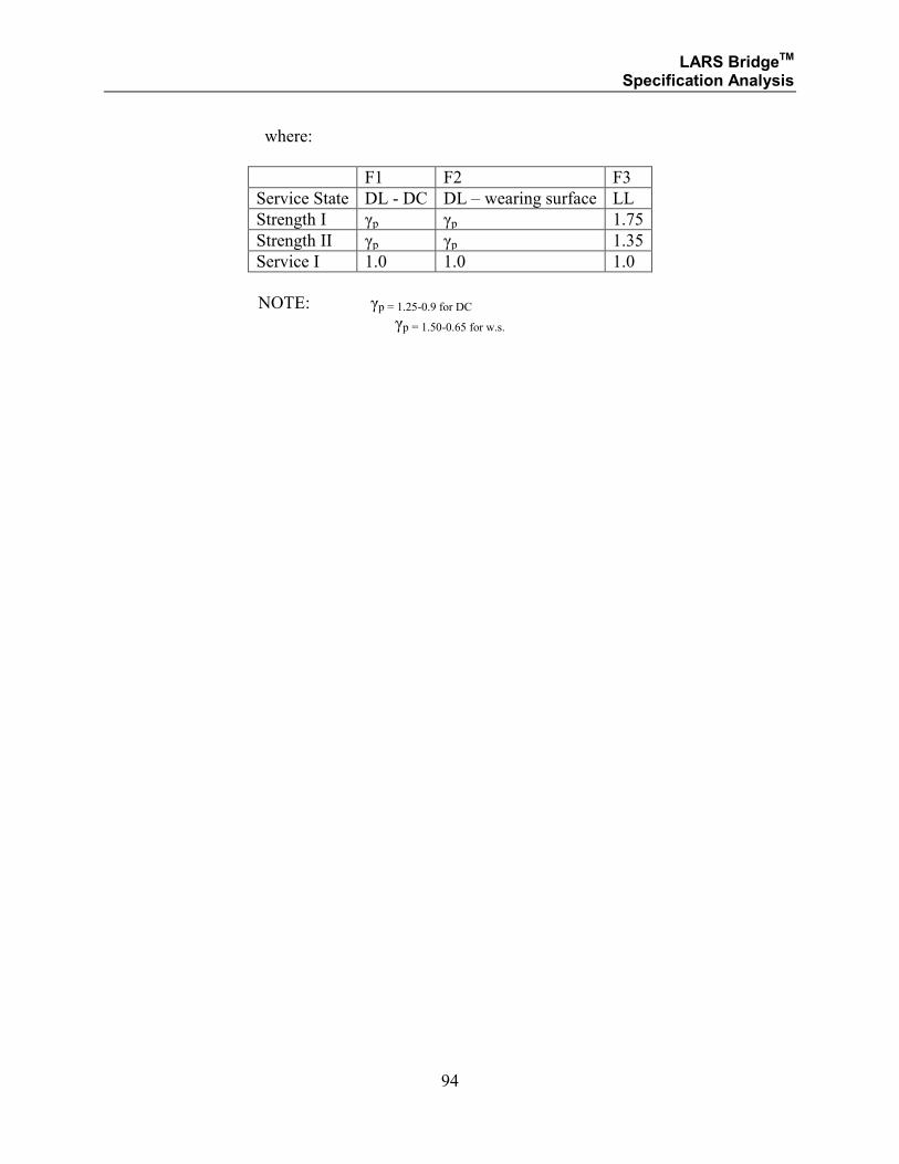
LARS BridgeTM Specification Analysis
94
where:
F1 F2 F3
Service State DL - DC DL – wearing surface LL
Strength I γp γp 1.75
Strength II γp γp 1.35
Service I 1.0 1.0 1.0
NOTE: γp = 1.25-0.9 for DC γp = 1.50-0.65 for w.s.
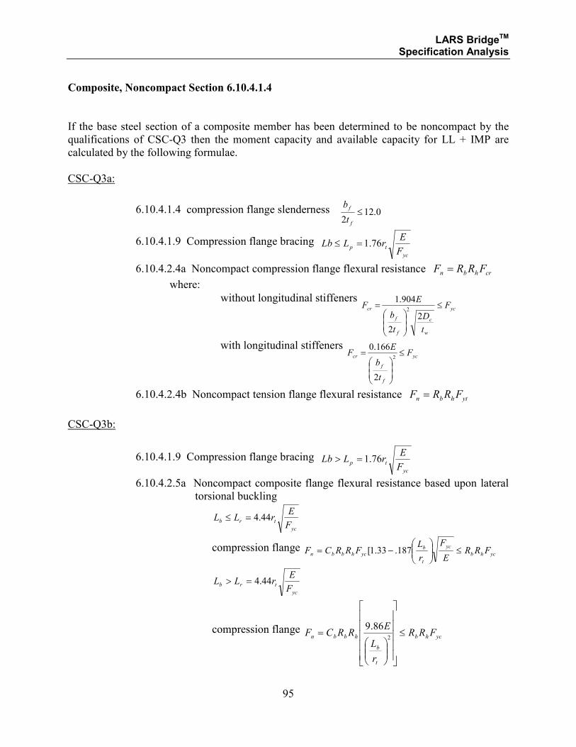
LARS BridgeTM Specification Analysis
95
Composite, Noncompact Section 6.10.4.1.4
If the base steel section of a composite member has been determined to be noncompact by the
qualifications of CSC-Q3 then the moment capacity and available capacity for LL + IMP are
calculated by the following formulae.
CSC-Q3a:
6.10.4.1.4 compression flange slenderness 0.122
≤f
f
t
b
6.10.4.1.9 Compression flange bracing yc
tpF
ErLLb 76.1=≤
6.10.4.2.4a Noncompact compression flange flexural resistance crhbn FRRF =
where:
without longitudinal stiffeners yc
w
c
f
f
cr F
t
D
t
b
EF ≤
=
2
2
904.12
with longitudinal stiffeners yc
f
f
cr F
t
b
EF ≤
=
2
2
166.0
6.10.4.2.4b Noncompact tension flange flexural resistance ythbn FRRF =
CSC-Q3b:
6.10.4.1.9 Compression flange bracing yc
tpF
ErLLb 76.1=>
6.10.4.2.5a Noncompact composite flange flexural resistance based upon lateral
torsional buckling
yc
trbF
ErLL 44.4=≤
compression flange ychb
yc
t
b
ychbbn FRRE
F
r
LFRRCF ≤
−= 187.33.1[
yc
trbF
ErLL 44.4=>
compression flange ychb
t
b
hbbn FRR
r
L
ERRCF ≤
=
2
86.9
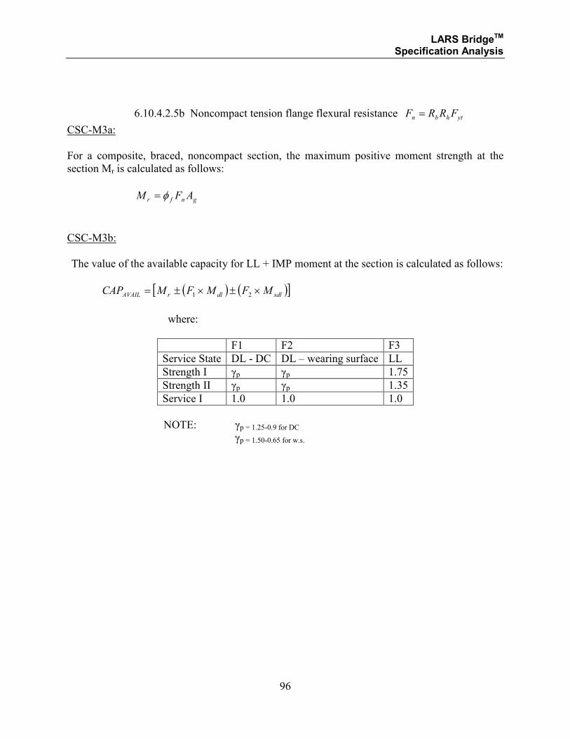
LARS BridgeTM Specification Analysis
96
6.10.4.2.5b Noncompact tension flange flexural resistance ythbn FRRF =
CSC-M3a:
For a composite, braced, noncompact section, the maximum positive moment strength at the
section Mr is calculated as follows:
gnfr AFM φ=
CSC-M3b:
The value of the available capacity for LL + IMP moment at the section is calculated as follows:
( ) ( )[ ]sdldlrAVAIL MFMFMCAP ×±×±= 21
where:
F1 F2 F3
Service State DL - DC DL – wearing surface LL
Strength I γp γp 1.75
Strength II γp γp 1.35
Service I 1.0 1.0 1.0
NOTE: γp = 1.25-0.9 for DC γp = 1.50-0.65 for w.s.
LARS BridgeTM Specification Analysis
97
SECTION 1.3
STRUCTURAL STEEL
AND
COMPOSITE STEEL AND CONCRETE
LOAD RESISTANCE AND FACTOR DESIGN METHOD
LARS BridgeTM Specification Analysis
98
LARS BridgeTM Specification Analysis
99
SECTION 1.3.2
COMPOSITE STRUCTURAL STEEL AND CONCRETE
LOAD RESISTANCE FACTOR DESIGN METHODS
STRENGTH LIMIT STATE ANALYSIS
FOR:
• COMPOSITE COMPACT SECTIONS
• COMPOSITE NONCOMPACT SECTIONS
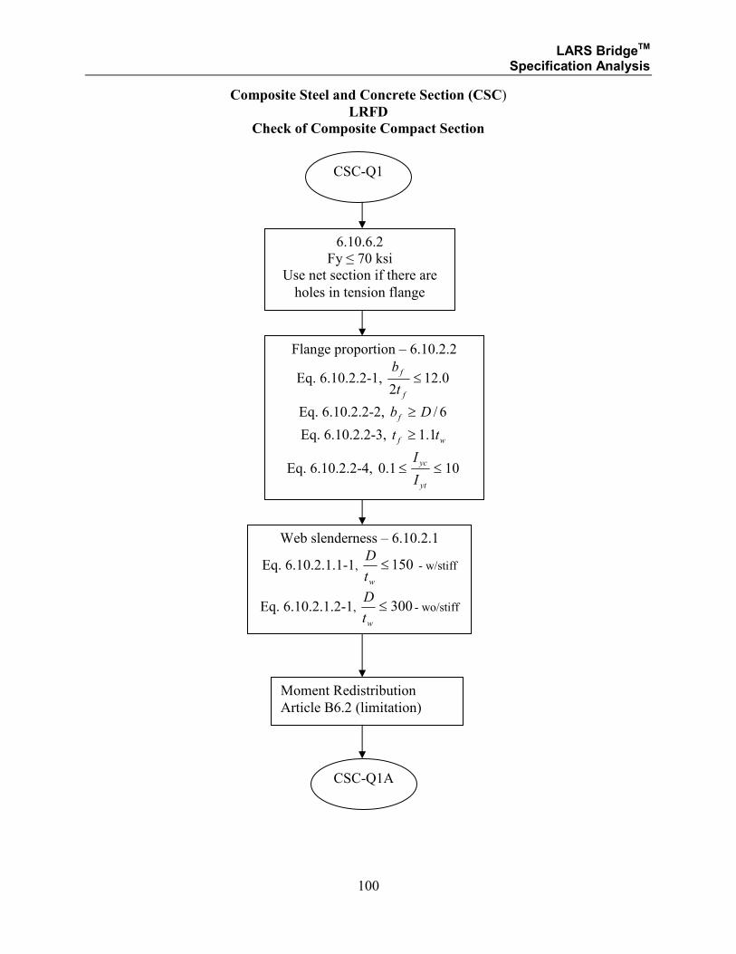
LARS BridgeTM Specification Analysis
100
Composite Steel and Concrete Section (CSC)
LRFD
Check of Composite Compact Section
6.10.6.2
Fy ≤ 70 ksi
Use net section if there are
holes in tension flange
CSC-Q1
Moment Redistribution
Article B6.2 (limitation)
Flange proportion – 6.10.2.2
Eq. 6.10.2.2-1, 0.122
≤f
f
t
b
Eq. 6.10.2.2-2, 6/Db f ≥
Eq. 6.10.2.2-3, wf tt 1.1≥
Eq. 6.10.2.2-4, 101.0 ≤≤yt
yc
I
I
Web slenderness – 6.10.2.1
Eq. 6.10.2.1.1-1, 150≤wt
D - w/stiff
Eq. 6.10.2.1.2-1, 300≤wt
D- wo/stiff
CSC-Q1A
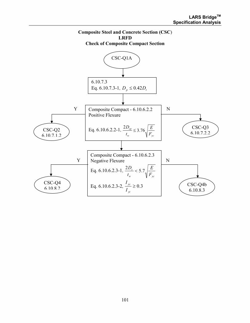
LARS BridgeTM Specification Analysis
101
Composite Steel and Concrete Section (CSC)
LRFD
Check of Composite Compact Section
CSC-Q1A
Composite Compact - 6.10.6.2.2
Positive Flexure
Eq. 6.10.6.2.2-1, ycw
cp
F
E
t
D76.3
2≤
N Y Composite Compact - 6.10.6.2.3
Negative Flexure
Eq. 6.10.6.2.3-1, ycw
c
F
E
t
D7.5
2<
Eq. 6.10.6.2.3-2, 3.0≥yt
yc
I
I
CSC-Q2
6.10.7.1.2
CSC-Q3
6.10.7.2.2
CSC-Q4
6.10.8.2 CSC-Q4b
6.10.8.3
N Y
6.10.7.3
Eq. 6.10.7.3-1, tp DD 42.0≤
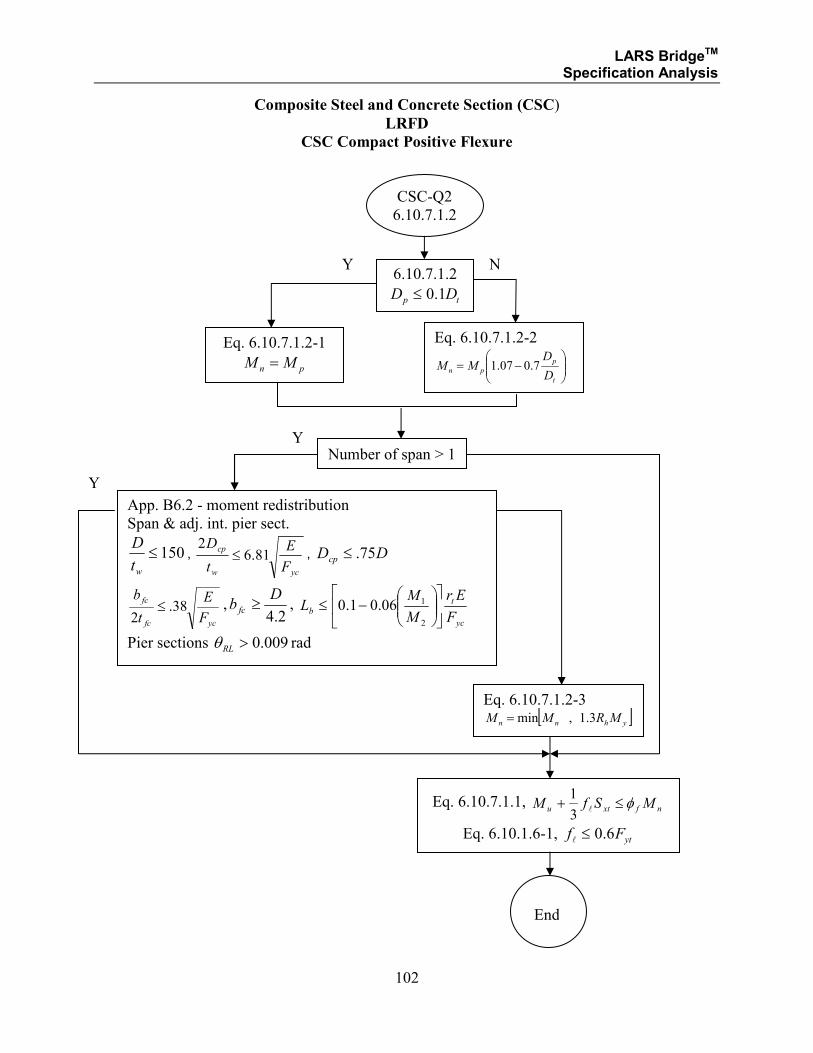
LARS BridgeTM Specification Analysis
102
Composite Steel and Concrete Section (CSC)
LRFD
CSC Compact Positive Flexure
6.10.7.1.2
tp DD 1.0≤
Eq. 6.10.7.1.2-1
pn MM =
Eq. 6.10.7.1.2-2
−=
t
p
pnD
DMM 7.007.1
CSC-Q2
6.10.7.1.2
Eq. 6.10.7.1.2-3 [ ]yhnn MRMM 3.1,min=
Y N
Number of span > 1 Y
App. B6.2 - moment redistribution
Span & adj. int. pier sect.
150≤wt
D,
ycw
cp
F
E
t
D81.6
2≤ , DDcp 75.≤
ycfc
fc
F
E
t
b38.
2≤ ,
2.4
Db fc ≥ ,
yc
tb
F
Er
M
ML
−≤
2
106.01.0
Pier sections 009.0>RLθ rad
Eq. 6.10.7.1.1, nfxtu MSfM φ≤+
l
3
1
Eq. 6.10.1.6-1, ytFf 6.0≤l
End
Y
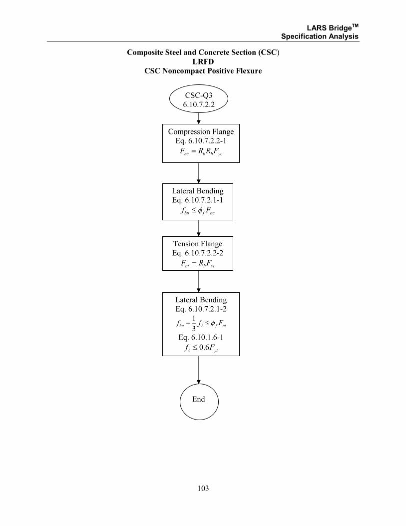
LARS BridgeTM Specification Analysis
103
Composite Steel and Concrete Section (CSC)
LRFD
CSC Noncompact Positive Flexure
Compression Flange
Eq. 6.10.7.2.2-1
ychbnc FRRF =
CSC-Q3
6.10.7.2.2
Lateral Bending
Eq. 6.10.7.2.1-2
ntfbu Fff φ≤+l
3
1
Eq. 6.10.1.6-1
ytFf 6.0≤l
End
Lateral Bending
Eq. 6.10.7.2.1-1
ncfbu Ff φ≤
Tension Flange
Eq. 6.10.7.2.2-2
ythnt FRF =
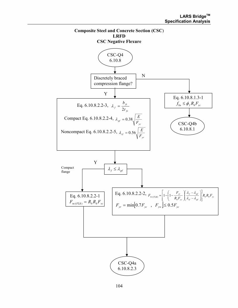
LARS BridgeTM Specification Analysis
104
Composite Steel and Concrete Section (CSC)
LRFD
CSC Negative Flexure
CSC-Q4
6.10.8
Y
Discretely braced
compression flange?
N
Y
Eq. 6.10.8.2.2-3, fc
fc
ft
b
2=λ
Compact Eq. 6.10.8.2.2-4, yc
pfF
E38.0=λ
Noncompact Eq. 6.10.8.2.2-5, yr
rfF
E56.0=λ
pff λλ ≤
Eq. 6.10.8.2.2-1
ychbFLBnc FRRF =)(
CSC-Q4b
6.10.8.1
Compact
flange
Eq. 6.10.8.2.2-2, ychb
pfrf
pff
ych
yr
FLBnc FRRFR
FF
−
−
−−=
λλ
λλ11
)(
[ ] ycywycyr FFFF 5.0,7.0min ≤=
CSC-Q4a
6.10.8.2.3
Eq. 6.10.8.1.3-1
ychfbu FRf φ≤
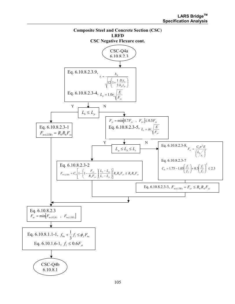
LARS BridgeTM Specification Analysis
105
Composite Steel and Concrete Section (CSC)
LRFD
CSC Negative Flexure cont.
Eq. 6.10.8.2.3.9,
+
=
fcfc
wc
fc
t
tb
tD
br
3
1112
Eq. 6.10.8.2.3-4, yc
tpF
ErL 0.1=
CSC-Q4a
6.10.8.2.3
pb LL ≤
Y N
Eq. 6.10.8.2.3-1
ychbLTBnc FRRF =)(
Eq. 6.10.8.2.3 [ ])()( ,min LTBncFLBncnc FFF =
Eq. 6.10.8.1.1-1, ncfbu Fff φ≤+
l
3
1
Eq. 6.10.1.6-1, ytFf 6.0≤l
[ ] ycywycyr FFFF 5.0,7.0min ≤=
Eq. 6.10.8.2.3-5,
yr
trF
ErL π=
rbp LLL ≤≤
Y N
Eq. 6.10.8.2.3-2
ychbychb
pr
pb
ych
yr
bLTBnc FRRFRRLL
LL
FR
FCF ≤
−
−
−−= 11
)(
Eq. 6.10.8.2.3-3, ychbcrLTBnc FRRFF ≤=)(
CSC-Q4b
6.10.8.1
Eq. 6.10.8.2.3-8,2
2
=
t
b
bcr
rL
ECF
π
Eq. 6.10.8.2.3-7
3.23.005.175.1
2
2
1
2
1 ≤
+
−=
f
f
f
fCb
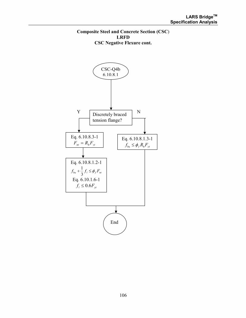
LARS BridgeTM Specification Analysis
106
Composite Steel and Concrete Section (CSC)
LRFD
CSC Negative Flexure cont.
Discretely braced
tension flange?
Y N
Eq. 6.10.8.1.3-1
ythfbu FRf φ≤
Eq. 6.10.8.3-1
ythnt FRF =
Eq. 6.10.8.1.2-1
ntfbu Fff φ≤+l
3
1
Eq. 6.10.1.6-1
ytFf 6.0≤l
End
CSC-Q4b
6.10.8.1
LARS BridgeTM Specification Analysis
107
Note: The area of the slab steel is included in the resisting capacity of the steel or
composite section when the steel is defined on input (i.e., RT 14), the CP is in the
negative moment area (i.e., within 0.3 of the span length either side of the interior
supports of continuous members, and then only for positive bending analysis).
LARS BridgeTM Specification Analysis
108
SECTION 1.2.5
STRUCTURAL STEEL
AND
COMPOSITE STEEL AND CONCRETE
LOAD RESISTANCE FACTOR DESIGN METHOD
SERVICE LIMIT STATE ANALYSIS
LARS BridgeTM Specification Analysis
109
Structural Steel (SS)/Composite Steel and Concrete (CSC)
LRFD
Service Limit State Analysis Method for SS/CSC Member
The following are descriptions of the methods for LARS to perform LFD service limit state
analysis. The elastic analysis specified in AASHTO LRFD 6.10.4 is used with the Load
Combination for Service II in AASHTO LRFD Table 3.4.1-1. The additional requirements for
service limit state are shown in SMS-Q1, and the available capacity is calculated by the formula
in SMS-M1.
For a SS/CSC member the moment resistance capacity is computed according AASHTO LRFD
6.10.4. In addition, the following requirements must be fulfilled.
SMS-Q1:
Web requirement (6.10.3.2.2): for SS - yw
w
cw F
t
D
kEf ≤
≤
2
9.0 α
for CSC - yw
w
c
cw F
t
D
kEf ≤
≤
2
9.0 α
Minimum negative slab reinforcement requirement (6.10.3.7):
a) total cross-sectional area > 1% of total slab cross-section area
when:
slab longitudinal tensile stress > rfφ
or
Load Combination Service II > rfφ
b) 60>yF ksi
c) Size > #6 bar
Flange stress (6.10.5.2): for SS - yff Ff 95.0≤
for CSC - yff Ff 80.0≤
NOTE: If satisfying the qualifications of 6.10.4.4 – moment redistribution may
be performed.
SMS-M1:
The value of the available capacity for LL + IMP moment at the section is calculated as follows:
( ) ( )[ ]sdldlrAVAIL MFMFMCAP ×±×±= 21
where:
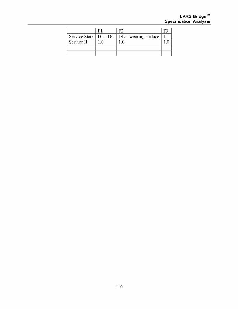
LARS BridgeTM Specification Analysis
110
F1 F2 F3
Service State DL - DC DL – wearing surface LL
Service II 1.0 1.0 1.0

LARS BridgeTM Specification Analysis
111
SECTION 1.2.6
STRUCTURAL STEEL
AND
COMPOSITE STEEL AND CONCRETE
LOAD RESISTANCE FACTOR DESIGN METHOD
FATIGUE LIMIT STATE ANALYSIS
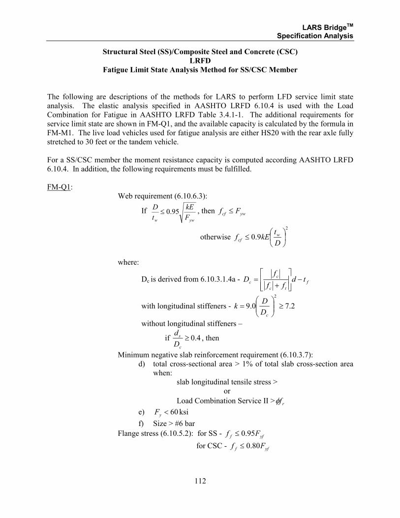
LARS BridgeTM Specification Analysis
112
Structural Steel (SS)/Composite Steel and Concrete (CSC)
LRFD
Fatigue Limit State Analysis Method for SS/CSC Member
The following are descriptions of the methods for LARS to perform LFD service limit state
analysis. The elastic analysis specified in AASHTO LRFD 6.10.4 is used with the Load
Combination for Fatigue in AASHTO LRFD Table 3.4.1-1. The additional requirements for
service limit state are shown in FM-Q1, and the available capacity is calculated by the formula in
FM-M1. The live load vehicles used for fatigue analysis are either HS20 with the rear axle fully
stretched to 30 feet or the tandem vehicle.
For a SS/CSC member the moment resistance capacity is computed according AASHTO LRFD
6.10.4. In addition, the following requirements must be fulfilled.
FM-Q1:
Web requirement (6.10.6.3):
If yww F
kE
t
D95.0≤ , then ywcf Ff ≤
otherwise
2
9.0
≤D
tkEf w
cf
where:
Dc is derived from 6.10.3.1.4a - f
tc
c
c tdff
fD −
+=
with longitudinal stiffeners - 2.70.9
2
≥
=
cD
Dk
without longitudinal stiffeners –
if 4.0≥c
s
D
d, then
Minimum negative slab reinforcement requirement (6.10.3.7):
d) total cross-sectional area > 1% of total slab cross-section area
when:
slab longitudinal tensile stress >
or
Load Combination Service II > rfφ
e) 60<yF ksi
f) Size > #6 bar
Flange stress (6.10.5.2): for SS - yff Ff 95.0≤
for CSC - yff Ff 80.0≤
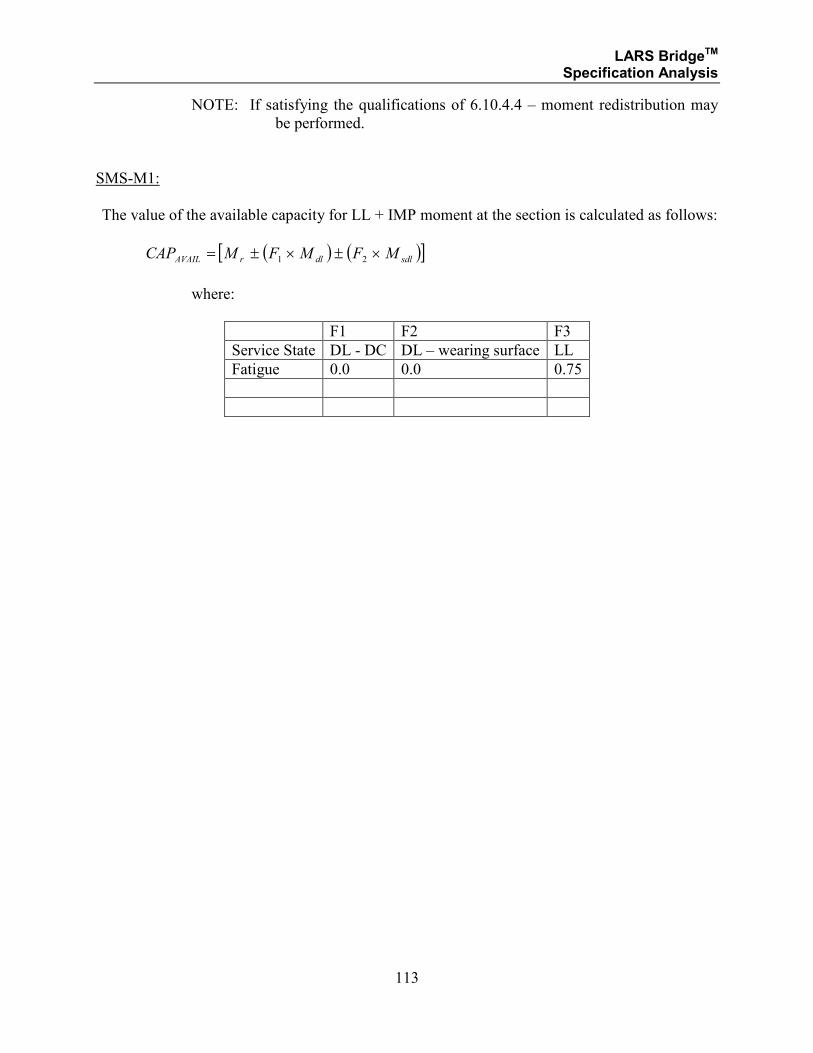
LARS BridgeTM Specification Analysis
113
NOTE: If satisfying the qualifications of 6.10.4.4 – moment redistribution may
be performed.
SMS-M1:
The value of the available capacity for LL + IMP moment at the section is calculated as follows:
( ) ( )[ ]sdldlrAVAIL MFMFMCAP ×±×±= 21
where:
F1 F2 F3
Service State DL - DC DL – wearing surface LL
Fatigue 0.0 0.0 0.75
LARS BridgeTM Specification Analysis
114
SECTION 1.2.3
STRUCTURAL STEEL
AND
COMPOSITE STEEL AND CONCRETE
LOAD RESISTANCE FACTOR DESIGN METHOD
MOMENT ANALYSIS
FOR:
• HYBRID GIRDERS

LARS BridgeTM Specification Analysis
115
Structural Steel (SS)/Composite Steel and Concrete (CSC)
LRFD
Hybrid Girders
Specification Reduction Factor Page
6.10.1.10.1 Reduction Factor 6-80
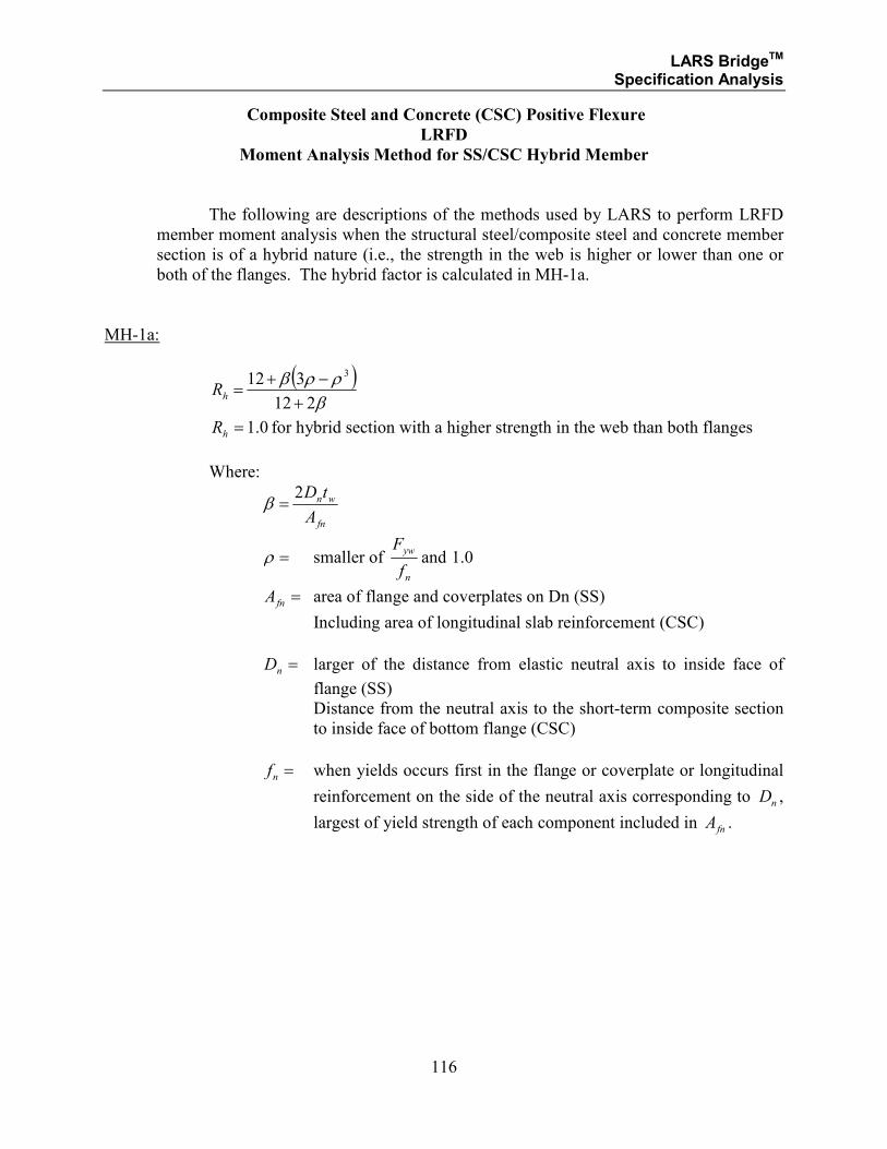
LARS BridgeTM Specification Analysis
116
Composite Steel and Concrete (CSC) Positive Flexure
LRFD
Moment Analysis Method for SS/CSC Hybrid Member
The following are descriptions of the methods used by LARS to perform LRFD
member moment analysis when the structural steel/composite steel and concrete member
section is of a hybrid nature (i.e., the strength in the web is higher or lower than one or
both of the flanges. The hybrid factor is calculated in MH-1a.
MH-1a:
( )βρρβ
212
312 3
+−+
=hR
0.1=hR for hybrid section with a higher strength in the web than both flanges
Where:
fn
wn
A
tD2=β
=ρ smaller of n
yw
f
Fand 0.1
=fnA area of flange and coverplates on Dn (SS)
Including area of longitudinal slab reinforcement (CSC)
=nD larger of the distance from elastic neutral axis to inside face of
flange (SS)
Distance from the neutral axis to the short-term composite section
to inside face of bottom flange (CSC)
=nf when yields occurs first in the flange or coverplate or longitudinal
reinforcement on the side of the neutral axis corresponding to nD ,
largest of yield strength of each component included in fnA .
LARS BridgeTM Specification Analysis
117
SECTION 1.2.4
STRUCTURAL STEEL
AND
COMPOSITE STEEL AND CONCRETE
LOAD RESISTANCE FACTOR DESIGN METHOD
Load Shedding Factor
LARS BridgeTM Specification Analysis
118
Structural Steel (SS)/Composite Steel and Concrete (CSC)
LRFD
Hybrid Girders
Specification Reduction Factor Page
6.10.1.10.2 Reduction Factor 6-81
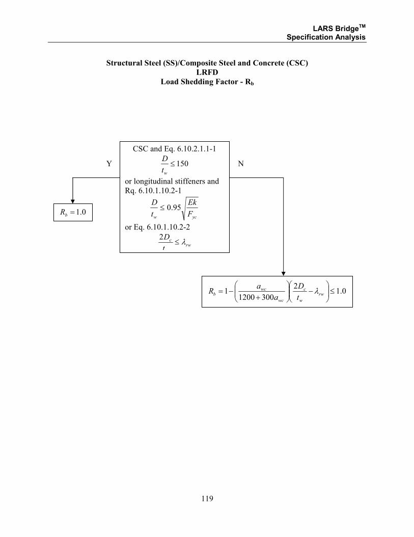
LARS BridgeTM Specification Analysis
119
Structural Steel (SS)/Composite Steel and Concrete (CSC)
LRFD
Load Shedding Factor - Rb
CSC and Eq. 6.10.2.1.1-1
150≤wt
D
or longitudinal stiffeners and
Rq. 6.10.1.10.2-1
ycw F
Ek
t
D95.0≤
or Eq. 6.10.1.10.2-2
rw
w
c
t
Dλ≤
2
Y N
0.1=bR
0.12
30012001 ≤
−
+−= rw
w
c
wc
wcb
t
D
a
aR λ
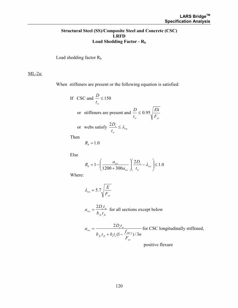
LARS BridgeTM Specification Analysis
120
Structural Steel (SS)/Composite Steel and Concrete (CSC)
LRFD
Load Shedding Factor - Rb
Load shedding factor Rb
ML-2a:
When stiffeners are present or the following equation is satisfied:
If CSC and 150≤wt
D
or stiffeners are present and ycw F
Ek
t
D95.0≤
or webs satisfy rw
w
c
t
Dλ≤
2
Then
0.1=bR
Else
0.12
30012001 ≤
−
+−= rw
w
c
wc
wcb
t
D
a
aR λ
Where:
yc
rwF
E7.5=λ
fcfc
wcwc
tb
tDa
2= for all sections except below
nF
ftbtb
tDa
yc
DCssfcfc
wcwc
3/)1(
2
1−+= for CSC longitudinally stiffened,
positive flexure
LARS BridgeTM Specification Analysis
121
SECTION 1.2.7
STRUCTURAL STEEL
AND
COMPOSITE STEEL AND CONCRETE
LOAD RESISTANCE FACTOR DESIGN METHOD
FOR
SERVICE LIMIT STATE ANALYSIS
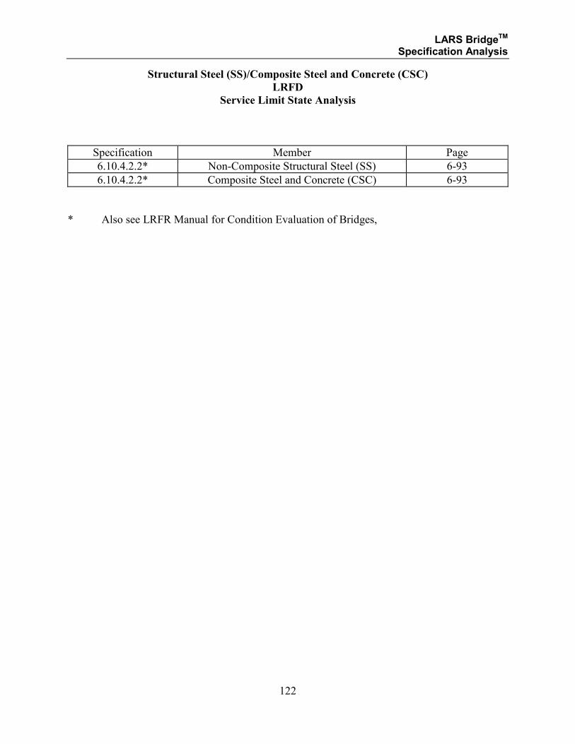
LARS BridgeTM Specification Analysis
122
Structural Steel (SS)/Composite Steel and Concrete (CSC)
LRFD
Service Limit State Analysis
Specification Member Page
6.10.4.2.2* Non-Composite Structural Steel (SS) 6-93
6.10.4.2.2* Composite Steel and Concrete (CSC) 6-93
* Also see LRFR Manual for Condition Evaluation of Bridges,
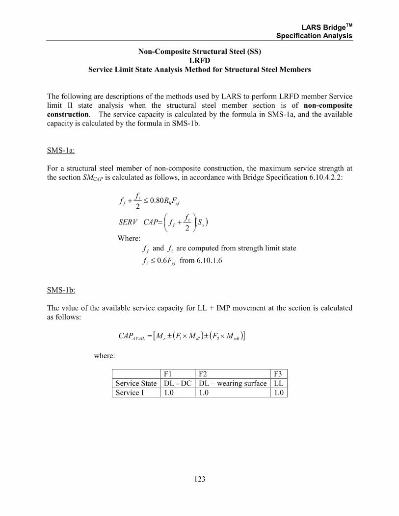
LARS BridgeTM Specification Analysis
123
Non-Composite Structural Steel (SS)
LRFD
Service Limit State Analysis Method for Structural Steel Members
The following are descriptions of the methods used by LARS to perform LRFD member Service
limit II state analysis when the structural steel member section is of non-composite
construction. The service capacity is calculated by the formula in SMS-1a, and the available
capacity is calculated by the formula in SMS-1b.
SMS-1a:
For a structural steel member of non-composite construction, the maximum service strength at
the section SMCAP is calculated as follows, in accordance with Bridge Specification 6.10.4.2.2:
( )xf
sfhf
Sf
fCAPSERV
FRf
f
+=
≤+
2
80.02
l
l
Where:
ff and lf are computed from strength limit state
yfFf 6.0≤l
from 6.10.1.6
SMS-1b:
The value of the available service capacity for LL + IMP movement at the section is calculated
as follows:
( ) ( )[ ]sdldlrAVAIL MFMFMCAP ×±×±= 21
where:
F1 F2 F3
Service State DL - DC DL – wearing surface LL
Service I 1.0 1.0 1.0
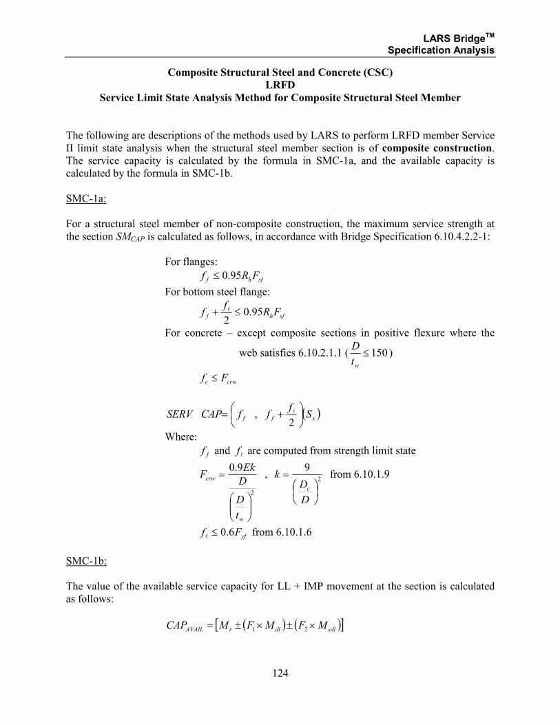
LARS BridgeTM Specification Analysis
124
Composite Structural Steel and Concrete (CSC)
LRFD
Service Limit State Analysis Method for Composite Structural Steel Member
The following are descriptions of the methods used by LARS to perform LRFD member Service
II limit state analysis when the structural steel member section is of composite construction.
The service capacity is calculated by the formula in SMC-1a, and the available capacity is
calculated by the formula in SMC-1b.
SMC-1a:
For a structural steel member of non-composite construction, the maximum service strength at
the section SMCAP is calculated as follows, in accordance with Bridge Specification 6.10.4.2.2-1:
For flanges:
sfhf FRf 95.0≤
For bottom steel flange:
sfhf FRf
f 95.02≤+ l
For concrete – except composite sections in positive flexure where the
web satisfies 6.10.2.1.1 ( 150≤wt
D)
crwc Ff ≤
( )xff Sf
ffCAPSERV
+=2
, l
Where:
ff and lf are computed from strength limit state
2
9.0
=
w
crw
t
D
D
EkF ,
2
9
=
D
Dk
c
from 6.10.1.9
yfFf 6.0≤l
from 6.10.1.6
SMC-1b:
The value of the available service capacity for LL + IMP movement at the section is calculated
as follows:
( ) ( )[ ]sdldlrAVAIL MFMFMCAP ×±×±= 21

LARS BridgeTM Specification Analysis
125
where:
F1 F2 F3
Service State DL - DC DL – wearing surface LL
Service I 1.0 1.0 1.0
LARS BridgeTM Specification Analysis
126
SECTION 1.2.4
STRUCTURAL STEEL
AND
COMPOSITE STEEL AND CONCRETE
LOAD FACTOR DESIGN METHOD
SHEAR ANALYSIS
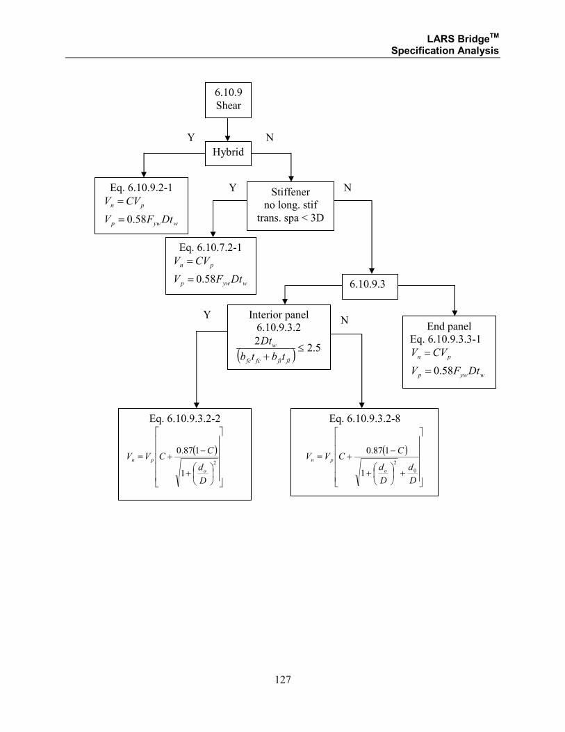
LARS BridgeTM Specification Analysis
127
6.10.9
Shear
Hybrid
Eq. 6.10.9.2-1
wywp
pn
DtFV
CVV
58.0=
=
6.10.9.3
Eq. 6.10.7.2-1
wywp
pn
DtFV
CVV
58.0=
=
Stiffener
no long. stif
trans. spa < 3D
Y
Y
N
N
Interior panel
6.10.9.3.2
( ) 5.22
≤+ ftftfcfc
w
tbtb
Dt
End panel
Eq. 6.10.9.3.3-1
wywp
pn
DtFV
CVV
58.0=
=
Eq. 6.10.9.3.2-2
( )
+
−+=
2
1
187.0
D
d
CCVV
o
pn
Eq. 6.10.9.3.2-8
( )
+
+
−+=
D
d
D
d
CCVV
o
pn
0
2
1
187.0
Y N
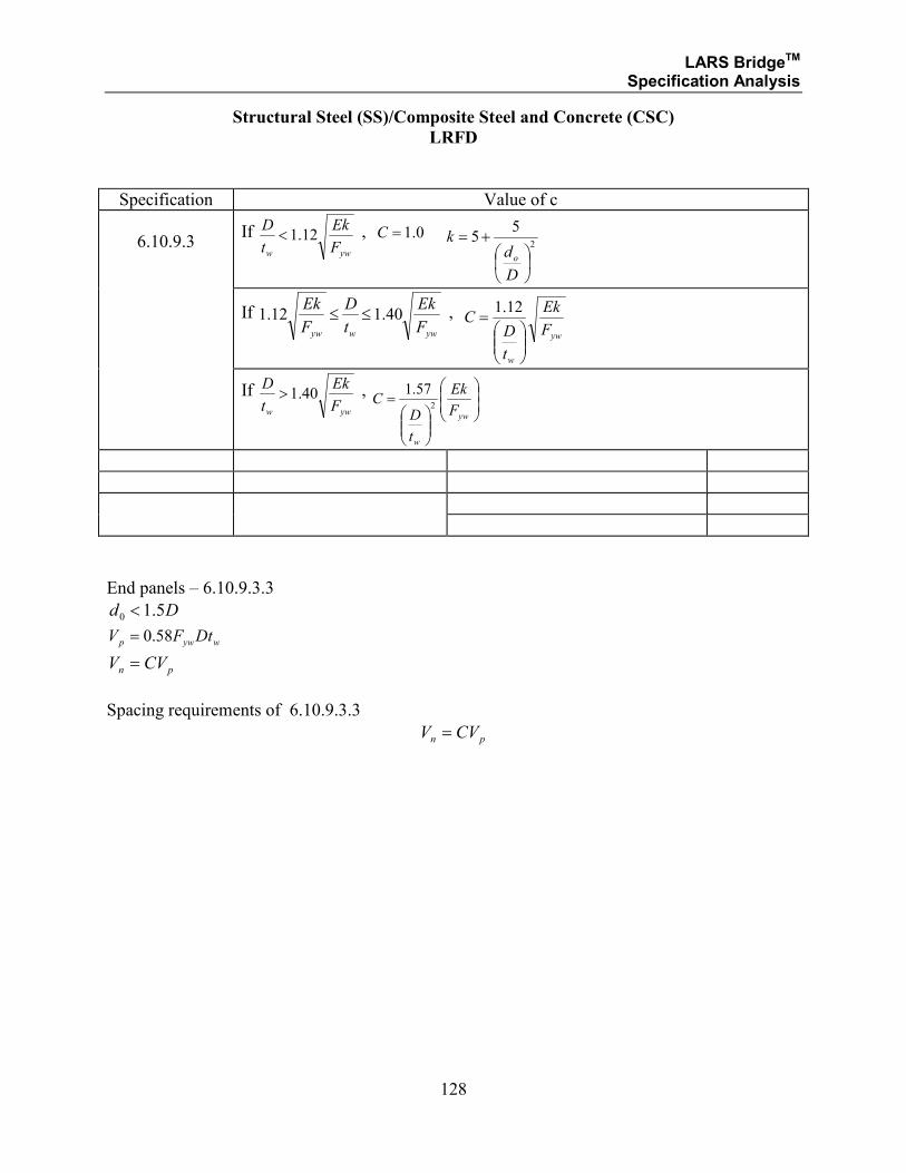
LARS BridgeTM Specification Analysis
128
Structural Steel (SS)/Composite Steel and Concrete (CSC)
LRFD
Specification Value of c
6.10.9.3
If yww F
Ek
t
D12.1< , 0.1=C
2
55
+=
D
dk
o
If ywwyw F
Ek
t
D
F
Ek40.112.1 ≤≤ ,
yw
w
F
Ek
t
DC
=
12.1
If
yww F
Ek
t
D40.1> ,
=
yw
w
F
Ek
t
DC
2
57.1
End panels – 6.10.9.3.3
Dd 5.10 <
wywp DtFV 58.0=
pn CVV =
Spacing requirements of 6.10.9.3.3
pn CVV =
LARS BridgeTM Specification Analysis
129
Structural Steel (SS)/Composite Steel and Concrete (CSC)
LRFD
Shear Analysis Method for SS/CSC Member
The following are descriptions of the methods for LARS to perform LFD shear analysis when
the member web is unstiffened for hybrid and homogeneous members. The shear capacity is
calculated by the formula in VS-1a, and the available capacity is calculated by the formula in
VS-1b.
For a SS/CSC member with web stiffened, the maximum shear strength at the section Vn
calculated as follows, in accordance with Bridge Specification 6.10.9.2:
VS-Q1:
pn CVV =
where
wywp DtFV 58.0=
VS-1a:
For a composite, unbraced, noncompact section, the maximum positive moment strength at the
section Vr is calculated as follows:
nvr VV φ=
VS-1b:
The value of the available capacity for LL + IMP moment at the section is calculated as follows:
( ) ( )[ ]sdldlrAVAIL VFVFVCAP ×±×±= 21
where:
F1 F2 F3
Service State DL - DC DL – wearing surface LL
Strength I γp γp 1.75
Strength II γp γp 1.35
Service I 1.0 1.0 1.0
NOTE: γp = 1.25-0.9 for DC γp = 1.50-0.65 for w.s.
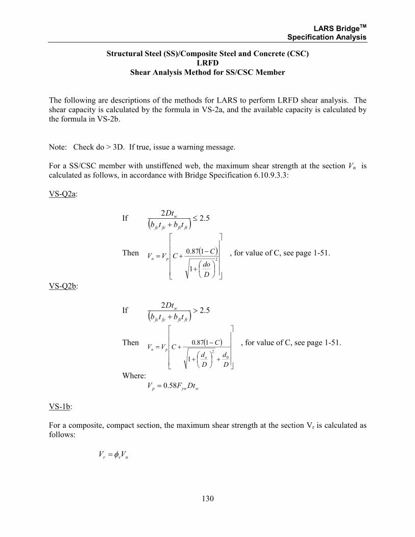
LARS BridgeTM Specification Analysis
130
Structural Steel (SS)/Composite Steel and Concrete (CSC)
LRFD
Shear Analysis Method for SS/CSC Member
The following are descriptions of the methods for LARS to perform LRFD shear analysis. The
shear capacity is calculated by the formula in VS-2a, and the available capacity is calculated by
the formula in VS-2b.
Note: Check do > 3D. If true, issue a warning message.
For a SS/CSC member with unstiffened web, the maximum shear strength at the section Vn is
calculated as follows, in accordance with Bridge Specification 6.10.9.3.3:
VS-Q2a:
If ( ) 5.22
≤+ ftftfcfc
w
tbtb
Dt
Then ( )
+
−+=
2
1
187.0
D
do
CCVV pn
, for value of C, see page 1-51.
VS-Q2b:
If ( ) 5.22
>+ ftftfcfc
w
tbtb
Dt
Then ( )
+
+
−+=
D
d
D
d
CCVV
o
pn
0
2
1
187.0 , for value of C, see page 1-51.
Where:
wywp DtFV 58.0=
VS-1b:
For a composite, compact section, the maximum shear strength at the section Vr is calculated as
follows:
nvr VV φ=
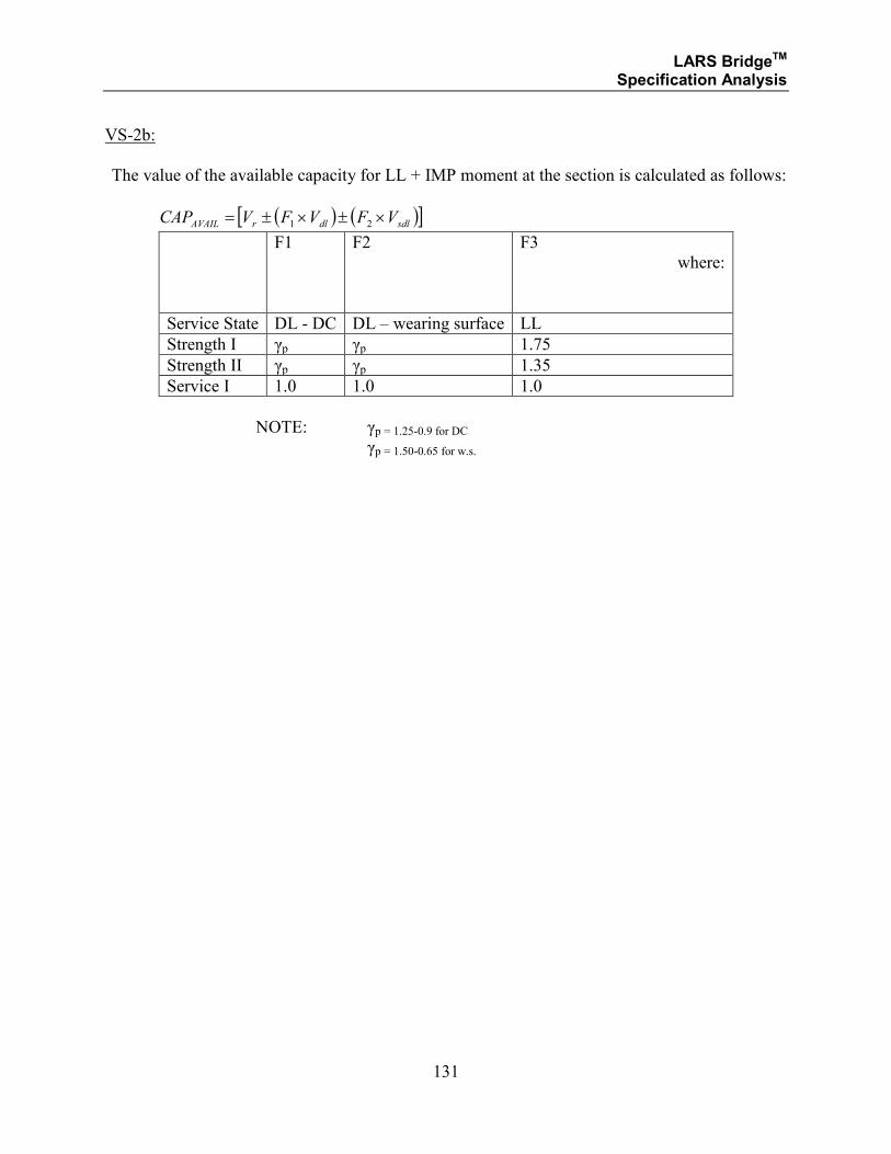
LARS BridgeTM Specification Analysis
131
VS-2b:
The value of the available capacity for LL + IMP moment at the section is calculated as follows:
( ) ( )[ ]sdldlrAVAIL VFVFVCAP ×±×±= 21
F1 F2 F3
where:
Service State DL - DC DL – wearing surface LL
Strength I γp γp 1.75
Strength II γp γp 1.35
Service I 1.0 1.0 1.0
NOTE: γp = 1.25-0.9 for DC γp = 1.50-0.65 for w.s.
LARS BridgeTM Specification Analysis
132
SECTION 2
REINFORCED CONCRETE
LARS BridgeTM Specification Analysis
133
Reinforced Concrete (RC)2
a = Depth of equivalent rectangular stress block (Article 8.16.2.7).
As = Area of tension reinforcement, sq.in.
As
' = Area of compression reinforcement, sq.in.
Asf = Area of reinforcement to develop compressive strength of overhanging flanges of
I- and T-sections (Article 8.16.3.3.2).
Av = Area of shear reinforcement within a distance s.
b = Width of compression face of member.
b’ = bw
bw = Web width, or diameter of circular section (Article 8.15.5.1.1).
CAPAVAIL= Available capacity in moment for Live Load + Impact.
d = Distance from extreme compression fiber to centroid of tension reinforcement.
d′ = Distance from extreme compression fiber to centroid of compression
reinforcement, in.
fc'
= Specified compression strength of concrete, psi.
fs = Tensile stress in reinforcement at service loads, psi (Article 8.15.2.2).
fy = Specified yield strength of reinforcement, psi.
F = Factor of rating type (inventory, operating, posting, etc.)
hf = Compression flange thickness of I- and T-sections.
j = Section value in a reinforced concrete section with ASD related to equivalent
moment arm (jd).
k = Section value in a reinforced concrete section with ASD related to equivalent
compressive depth (kd).
2 Selected symbols and references are based on AASHTO Standard Specifications for Highway Bridges, Sixteenth
Edition, while other symbols and references are unique to LARS.
LARS BridgeTM Specification Analysis
134
M = Computed moment capacity (Article 8.24.2.3).
MCAP * = Moment capacity.
Mdl * = Dead load moment at the section.
Mn = Nominal moment strength of a section.
Msdl * = Superimposed dead load moment at the section.
Mu = Factored moment at section.
n = Modular ratio of elasticity = Es/Ec (Article 8.15.3.4).
s = Spacing of shear reinforcement in the direction parallel to the longitudinal
reinforcement.
vc = Allowable shear stress of concrete.
vs = Allowable shear stress of shear reinforcement.
V = Total shear force at section.
Vc = Nominal shear strength provided by concrete (Article 8.16.6.1).
Vs = Nominal shear strength provided by shear reinforcement (Article 8.16.6.1).
Vu = Factored shear force at section (Article 8.16.6.1).
VAVAIL *= Available capacity in shear for Live Load + Impact.
VDL * = Dead load shear.
VSDL * = Superimposed dead load shear.
α = Angle between inclined shear reinforcement and longitudinal axis of member.
φ = Strength reduction factor (Article 8.16.1.2).
ρ = Tension reinforcement ratio = As/bwd, As/bd.
LARS BridgeTM Specification Analysis
135
Reinforced Concrete (RC)
The various criteria logic that is used to determine the calculation methods for the various
analysis conditions are referenced below by number. The calculation methods and formulae are
referenced by number.
ASD
ASD analysis will be performed for every flexural member that has data sufficient for this
analysis, regardless of whether an LFD analysis is requested.
Non-Composite:
• All reinforced concrete members will be analyzed as non-composite since composite
reinforced concrete member analysis is not included in LARS Release 1.7 or 2.0.
• The values for available capacity for LL + IMP and moment capacity for all non-
composite members are calculated by the formulae.
LFD
Non-Composite:
• All reinforced concrete members will be analyzed as non-composite since composite
reinforced concrete member analysis is not included in LARS Release 1.7 or 2.0.
• The values for available capacity for LL + IMP and moment capacity for all non-
composite members are calculated by the formulae.
LARS BridgeTM Specification Analysis
136
SECTION 2.1
REINFORCED CONCRETE
ALLOWABLE STRESS DESIGN METHOD
LARS BridgeTM Specification Analysis
137
SECTION 2.1.1
REINFORCED CONCRETE
ALLOWABLE STRESS DESIGN METHOD
MOMENT ANALYSIS
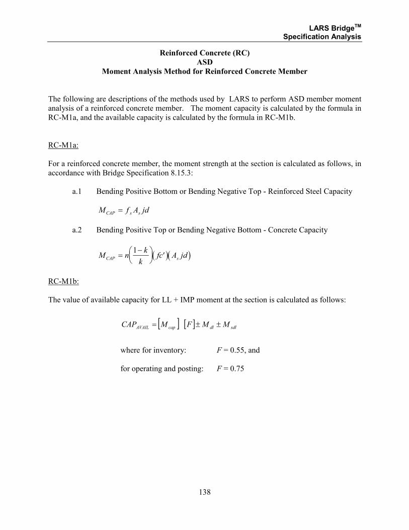
LARS BridgeTM Specification Analysis
138
Reinforced Concrete (RC)
ASD
Moment Analysis Method for Reinforced Concrete Member
The following are descriptions of the methods used by LARS to perform ASD member moment
analysis of a reinforced concrete member. The moment capacity is calculated by the formula in
RC-M1a, and the available capacity is calculated by the formula in RC-M1b.
RC-M1a:
For a reinforced concrete member, the moment strength at the section is calculated as follows, in
accordance with Bridge Specification 8.15.3:
a.1 Bending Positive Bottom or Bending Negative Top - Reinforced Steel Capacity
M f A jdCAP s s=
a.2 Bending Positive Top or Bending Negative Bottom - Concrete Capacity
( )( )M nk
kfc A jdCAP s=
−
′
1
RC-M1b:
The value of available capacity for LL + IMP moment at the section is calculated as follows:
[ ] [ ] sdldlcapAVAIL MMFMCAP ±±=
where for inventory: F = 0.55, and
for operating and posting: F = 0.75
LARS BridgeTM Specification Analysis
139
SECTION 2.1.2
REINFORCED CONCRETE
ALLOWABLE STRESS DESIGN METHOD
SHEAR ANALYSIS
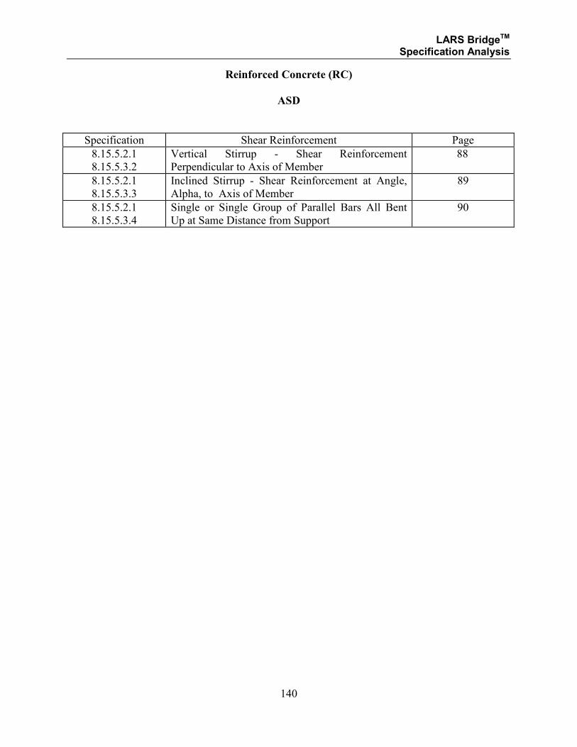
LARS BridgeTM Specification Analysis
140
Reinforced Concrete (RC)
ASD
Specification Shear Reinforcement Page
8.15.5.2.1
8.15.5.3.2
Vertical Stirrup - Shear Reinforcement
Perpendicular to Axis of Member
88
8.15.5.2.1
8.15.5.3.3
Inclined Stirrup - Shear Reinforcement at Angle,
Alpha, to Axis of Member
89
8.15.5.2.1
8.15.5.3.4
Single or Single Group of Parallel Bars All Bent
Up at Same Distance from Support
90
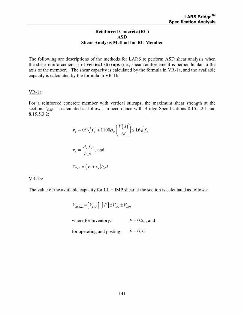
LARS BridgeTM Specification Analysis
141
Reinforced Concrete (RC)
ASD
Shear Analysis Method for RC Member
The following are descriptions of the methods for LARS to perform ASD shear analysis when
the shear reinforcement is of vertical stirrups (i.e., shear reinforcement is perpendicular to the
axis of the member). The shear capacity is calculated by the formula in VR-1a, and the available
capacity is calculated by the formula in VR-1b.
VR-1a:
For a reinforced concrete member with vertical stirrups, the maximum shear strength at the
section VCAP is calculated as follows, in accordance with Bridge Specifications 8.15.5.2.1 and
8.15.5.3.2:
( )
v fV d
Mfc c m c= +
≤09 1100 16. .' 'ρ
vA f
b ss
v s
w
= , and
( )V v v b dCAP c s w= +
VR-1b:
The value of the available capacity for LL + IMP shear at the section is calculated as follows:
[ ] [ ]V V F V VAVAIL CAP DL SDL= ± ±
where for inventory: F = 0.55, and
for operating and posting: F = 0.75
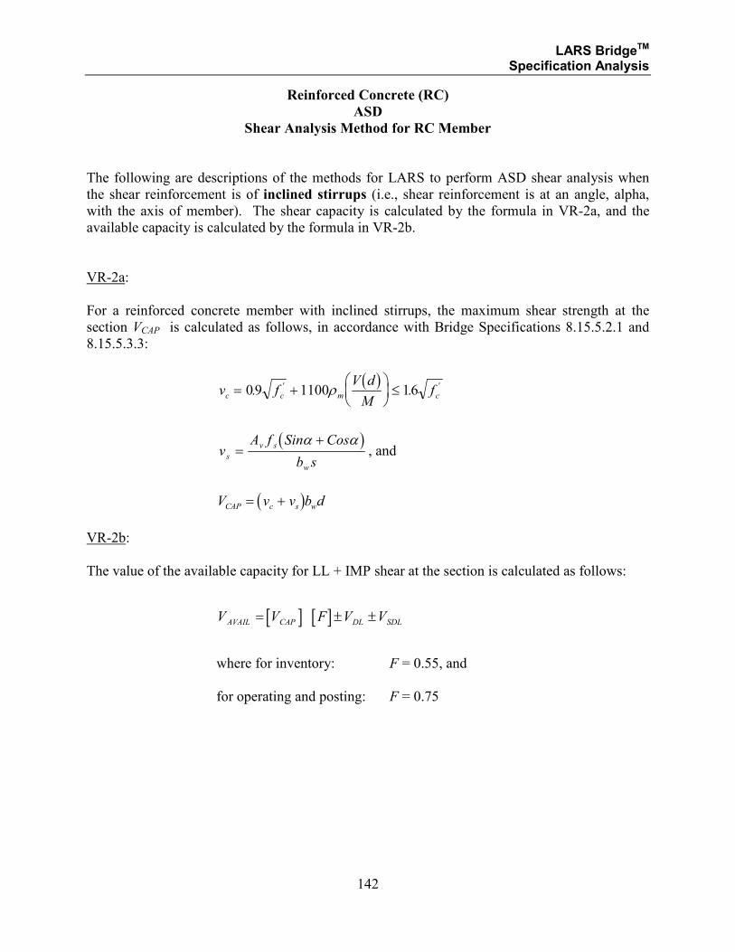
LARS BridgeTM Specification Analysis
142
Reinforced Concrete (RC)
ASD
Shear Analysis Method for RC Member
The following are descriptions of the methods for LARS to perform ASD shear analysis when
the shear reinforcement is of inclined stirrups (i.e., shear reinforcement is at an angle, alpha,
with the axis of member). The shear capacity is calculated by the formula in VR-2a, and the
available capacity is calculated by the formula in VR-2b.
VR-2a:
For a reinforced concrete member with inclined stirrups, the maximum shear strength at the
section VCAP is calculated as follows, in accordance with Bridge Specifications 8.15.5.2.1 and
8.15.5.3.3:
( )
v fV d
Mfc c m c= +
≤09 1100 16. .' 'ρ
( )
vA f Sin Cos
b ss
v s
w
=+α α
, and
( )V v v b dCAP c s w= +
VR-2b:
The value of the available capacity for LL + IMP shear at the section is calculated as follows:
[ ] [ ]V V F V VAVAIL CAP DL SDL= ± ±
where for inventory: F = 0.55, and
for operating and posting: F = 0.75
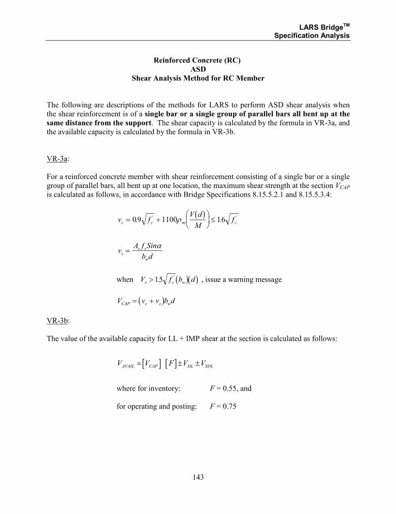
LARS BridgeTM Specification Analysis
143
Reinforced Concrete (RC)
ASD
Shear Analysis Method for RC Member
The following are descriptions of the methods for LARS to perform ASD shear analysis when
the shear reinforcement is of a single bar or a single group of parallel bars all bent up at the
same distance from the support. The shear capacity is calculated by the formula in VR-3a, and
the available capacity is calculated by the formula in VR-3b.
VR-3a:
For a reinforced concrete member with shear reinforcement consisting of a single bar or a single
group of parallel bars, all bent up at one location, the maximum shear strength at the section VCAP
is calculated as follows, in accordance with Bridge Specifications 8.15.5.2.1 and 8.15.5.3.4:
( )
v fV d
Mfc c m c= +
≤09 1100 16. .' 'ρ
vA f Sin
b ds
v s
w
=α
when ( )( )V f b ds c w> 15. ' , issue a warning message
( )V v v b dCAP c s w= +
VR-3b:
The value of the available capacity for LL + IMP shear at the section is calculated as follows:
[ ] [ ]V V F V VAVAIL CAP DL SDL= ± ±
where for inventory: F = 0.55, and
for operating and posting: F = 0.75
LARS BridgeTM Specification Analysis
144
SECTION 2.2
REINFORCED CONCRETE
LOAD FACTOR DESIGN METHOD
LARS BridgeTM Specification Analysis
145
SECTION 2.2.1
REINFORCED CONCRETE
LOAD FACTOR DESIGN METHOD
MOMENT ANALYSIS
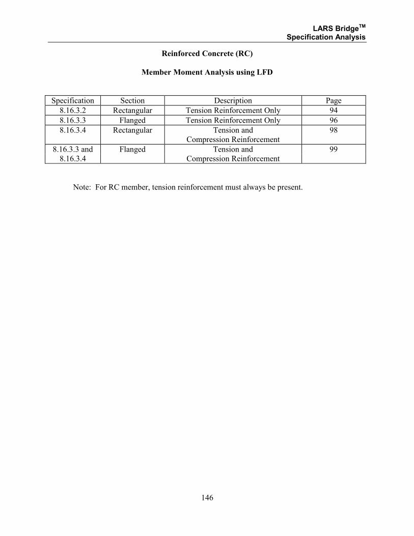
LARS BridgeTM Specification Analysis
146
Reinforced Concrete (RC)
Member Moment Analysis using LFD
Specification Section Description Page
8.16.3.2 Rectangular Tension Reinforcement Only 94
8.16.3.3 Flanged Tension Reinforcement Only 96
8.16.3.4 Rectangular Tension and
Compression Reinforcement
98
8.16.3.3 and Flanged Tension and 99
8.16.3.4 Compression Reinforcement
Note: For RC member, tension reinforcement must always be present.
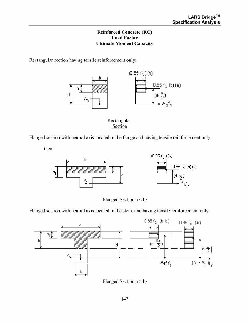
LARS BridgeTM Specification Analysis
147
Reinforced Concrete (RC)
Load Factor
Ultimate Moment Capacity
Rectangular section having tensile reinforcement only:
Rectangular
Section
Flanged section with neutral axis located in the flange and having tensile reinforcement only:
then
Flanged Section a < hf
Flanged section with neutral axis located in the stem, and having tensile reinforcement only.
Flanged Section a > hf
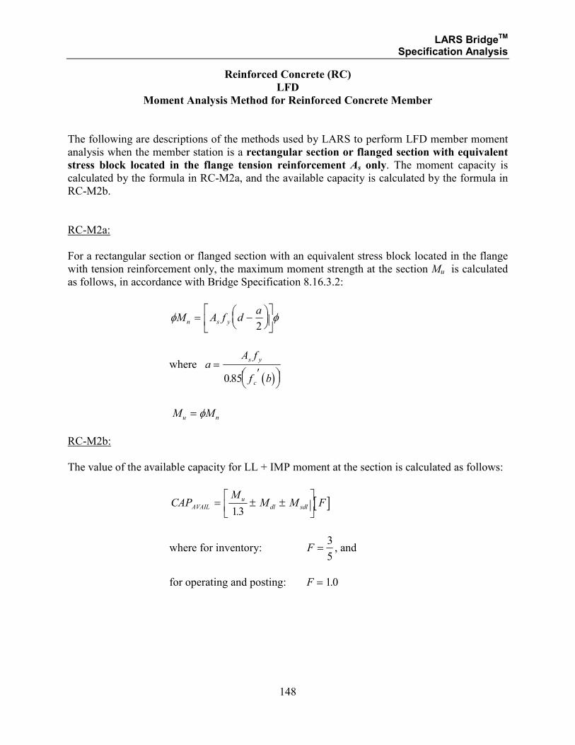
LARS BridgeTM Specification Analysis
148
Reinforced Concrete (RC)
LFD
Moment Analysis Method for Reinforced Concrete Member
The following are descriptions of the methods used by LARS to perform LFD member moment
analysis when the member station is a rectangular section or flanged section with equivalent
stress block located in the flange tension reinforcement As only. The moment capacity is
calculated by the formula in RC-M2a, and the available capacity is calculated by the formula in
RC-M2b.
RC-M2a:
For a rectangular section or flanged section with an equivalent stress block located in the flange
with tension reinforcement only, the maximum moment strength at the section Mu is calculated
as follows, in accordance with Bridge Specification 8.16.3.2:
φ φM A f da
n s y= −
2
where
( )a
A f
f b
s y
c
=′
085.
M Mu n= φ
RC-M2b:
The value of the available capacity for LL + IMP moment at the section is calculated as follows:
[ ]CAPM
M M FAVAIL
u
dl sdl= ± ±
13.
where for inventory: F =3
5, and
for operating and posting: F = 10.
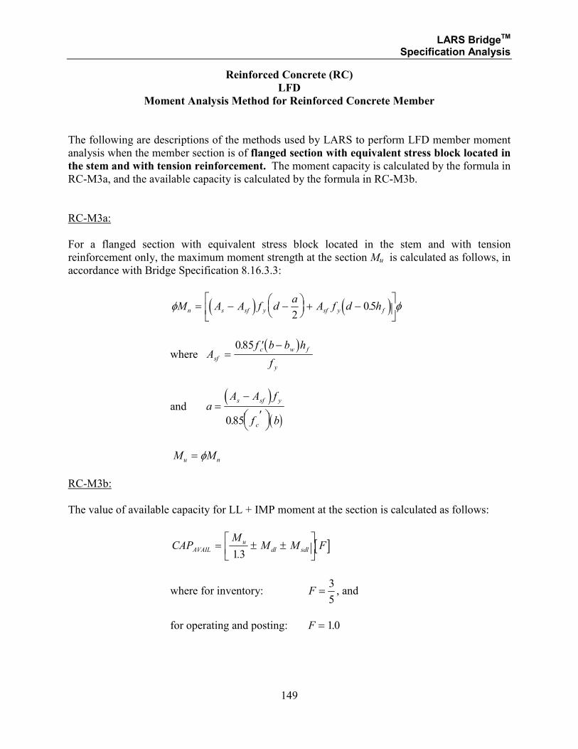
LARS BridgeTM Specification Analysis
149
Reinforced Concrete (RC)
LFD
Moment Analysis Method for Reinforced Concrete Member
The following are descriptions of the methods used by LARS to perform LFD member moment
analysis when the member section is of flanged section with equivalent stress block located in
the stem and with tension reinforcement. The moment capacity is calculated by the formula in
RC-M3a, and the available capacity is calculated by the formula in RC-M3b.
RC-M3a:
For a flanged section with equivalent stress block located in the stem and with tension
reinforcement only, the maximum moment strength at the section Mu is calculated as follows, in
accordance with Bridge Specification 8.16.3.3:
( ) ( )φ φM A A f da
A f d hn s sf y sf y f= − −
+ −
2
05.
where ( )
Af b b h
fsf
c w f
y
=′ −085.
and ( )
( )a
A A f
f b
s sf y
c
=−
′
085.
M Mu n= φ
RC-M3b:
The value of available capacity for LL + IMP moment at the section is calculated as follows:
[ ]CAPM
M M FAVAIL
u
dl sdl= ± ±
13.
where for inventory: F =3
5, and
for operating and posting: F = 10.
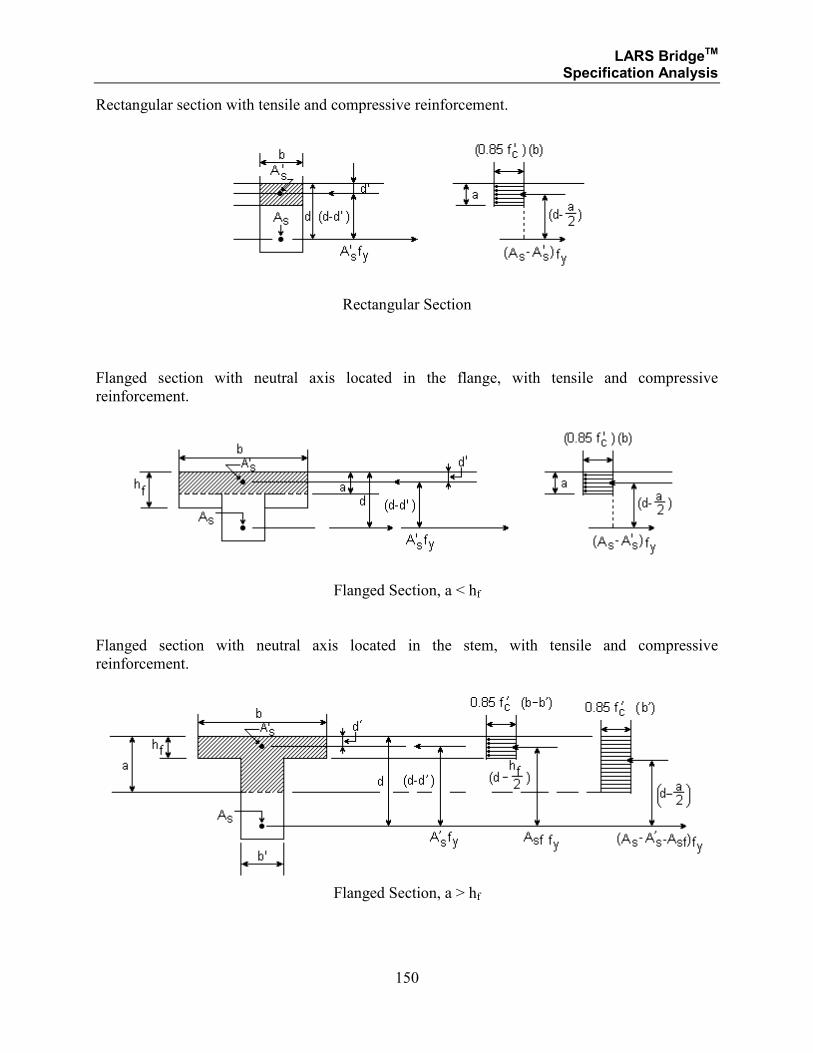
LARS BridgeTM Specification Analysis
150
Rectangular section with tensile and compressive reinforcement.
Rectangular Section
Flanged section with neutral axis located in the flange, with tensile and compressive
reinforcement.
Flanged Section, a < hf
Flanged section with neutral axis located in the stem, with tensile and compressive
reinforcement.
Flanged Section, a > hf
LARS BridgeTM Specification Analysis
151
Reinforced Concrete (RC)
LFD
Moment Analysis Method for Reinforced Concrete Members
The following are descriptions of the methods for LARS to perform LFD member moment
analysis when the member section is a rectangular section or flanged section with equivalent
stress block located in the flange and with tension reinforcement As , and compression
reinforcement As
′. The moment capacity is calculated by the formula in RC-M4a, and the
available capacity is calculated by the formula in RC-M4b.
RC-M4a:
For a rectangular section or flanged section with an equivalent stress block located in the flange
and with tension reinforcement and compression reinforcement, the maximum moment strength
at the section Mu is calculated as follows, in accordance with Bridge Specification 8.16.3.4:
( )φ φM A A f da
A f d dn s s y s y= − ′
−
+
′ − ′
2
where ( )
( )a
A A f
f b
s s y
c
=− ′
′
085.
M Mu n= φ
RC-M4b:
The value of the available capacity for LL + IMP moment at the section is calculated as follows:
[ ]CAPM
M M FAVAIL
u
dl sdl= ± ±
13.
where for inventory: F =3
5, and
for operating and posting: F = 10.
LARS BridgeTM Specification Analysis
152
Reinforced Concrete (RC)
LFD
Moment Analysis Method for Reinforced Concrete Member
The following are descriptions of the methods for LARS to perform LFD member moment
analysis, when the member section is of a flanged section with the equivalent stress block
located in the stem, with tension reinforcement As , and compression reinforcement As
′.
The moment capacity is calculated by the formula in RC-M5a, and the available capacity is
calculated by the formula in RC-M5b.
RC-M5a:
For a flanged section with an equivalent stress block located in the stem, with tension
reinforcement and compression reinforcement, the maximum moment strength at the section Mu
is calculated as follows, in accordance with Bridge Specifications 8.16.3.3 and 8.16.3.4:
( ) ( )φ φM A A A f da
A f d d A f d hn s s sf y s y sf y f= − ′ −
−
+
′ − ′ + −
2
05.
where ( )
Af b b h
fsf
c f
y
=′ − ′085.
and
( )a
A A A f
f b
s s sf y
c
=− ′ −
′
085.
M Mu n= φ
RC-M5b:
The value of the available capacity for LL + IMP moment at the section is calculated as follows:
[ ]CAPM
M M FAVAIL
u
dl sdl= ± ±
13.
where for inventory: F =3
5, and
for operating and posting: F = 10.
LARS BridgeTM Specification Analysis
153
SECTION 2.2.2
REINFORCED CONCRETE
LOAD FACTOR DESIGN METHOD
SHEAR ANALYSIS
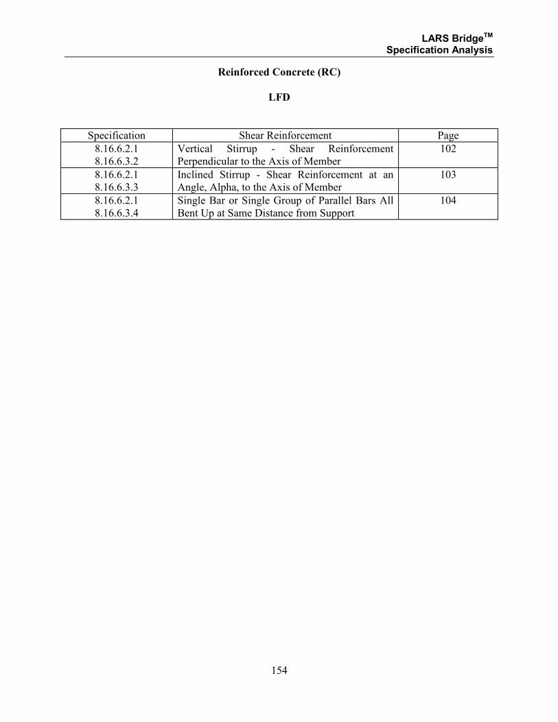
LARS BridgeTM Specification Analysis
154
Reinforced Concrete (RC)
LFD
Specification Shear Reinforcement Page
8.16.6.2.1
8.16.6.3.2
Vertical Stirrup - Shear Reinforcement
Perpendicular to the Axis of Member
102
8.16.6.2.1
8.16.6.3.3
Inclined Stirrup - Shear Reinforcement at an
Angle, Alpha, to the Axis of Member
103
8.16.6.2.1
8.16.6.3.4
Single Bar or Single Group of Parallel Bars All
Bent Up at Same Distance from Support
104
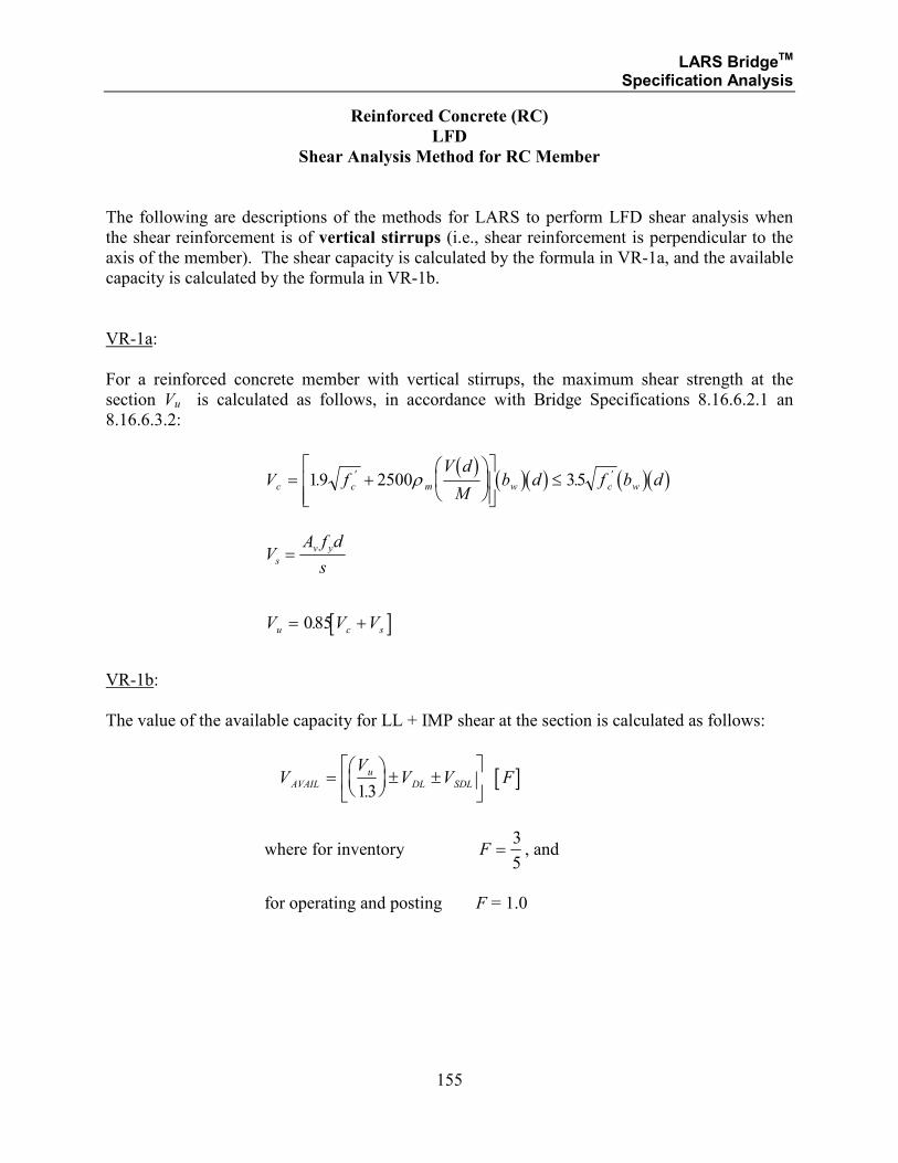
LARS BridgeTM Specification Analysis
155
Reinforced Concrete (RC)
LFD
Shear Analysis Method for RC Member
The following are descriptions of the methods for LARS to perform LFD shear analysis when
the shear reinforcement is of vertical stirrups (i.e., shear reinforcement is perpendicular to the
axis of the member). The shear capacity is calculated by the formula in VR-1a, and the available
capacity is calculated by the formula in VR-1b.
VR-1a:
For a reinforced concrete member with vertical stirrups, the maximum shear strength at the
section Vu is calculated as follows, in accordance with Bridge Specifications 8.16.6.2.1 an
8.16.6.3.2:
( ) ( )( ) ( )( )V f
V d
Mb d f b dc c m w c w= +
≤19 2500 35. .' 'ρ
VA f d
ss
v y=
[ ]V V Vu c s= +085.
VR-1b:
The value of the available capacity for LL + IMP shear at the section is calculated as follows:
[ ]VV
V V FAVAIL
u
DL SDL=
± ±
13.
where for inventory F =3
5, and
for operating and posting F = 1.0
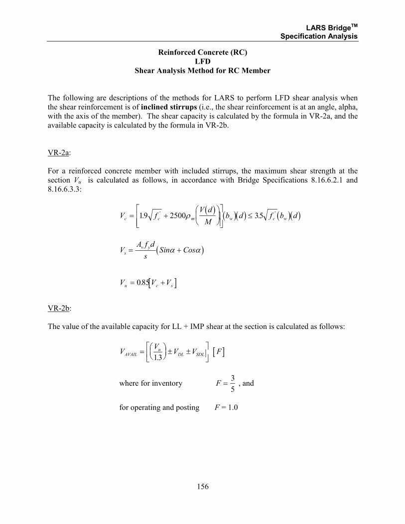
LARS BridgeTM Specification Analysis
156
Reinforced Concrete (RC)
LFD
Shear Analysis Method for RC Member
The following are descriptions of the methods for LARS to perform LFD shear analysis when
the shear reinforcement is of inclined stirrups (i.e., the shear reinforcement is at an angle, alpha,
with the axis of the member). The shear capacity is calculated by the formula in VR-2a, and the
available capacity is calculated by the formula in VR-2b.
VR-2a:
For a reinforced concrete member with included stirrups, the maximum shear strength at the
section Vu is calculated as follows, in accordance with Bridge Specifications 8.16.6.2.1 and
8.16.6.3.3:
( ) ( )( ) ( )( )V f
V d
Mb d f b dc c m w c w= +
≤19 2500 35. .' 'ρ
( )VA f d
sSin Coss
v y= +α α
[ ]V V Vu c s= +085.
VR-2b:
The value of the available capacity for LL + IMP shear at the section is calculated as follows:
[ ]VV
V V FAVAILu
DL SDL=
± ±
13.
where for inventory F =3
5 , and
for operating and posting F = 1.0
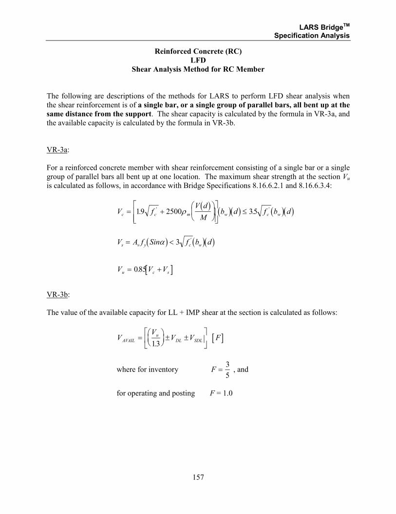
LARS BridgeTM Specification Analysis
157
Reinforced Concrete (RC)
LFD
Shear Analysis Method for RC Member
The following are descriptions of the methods for LARS to perform LFD shear analysis when
the shear reinforcement is of a single bar, or a single group of parallel bars, all bent up at the
same distance from the support. The shear capacity is calculated by the formula in VR-3a, and
the available capacity is calculated by the formula in VR-3b.
VR-3a:
For a reinforced concrete member with shear reinforcement consisting of a single bar or a single
group of parallel bars all bent up at one location. The maximum shear strength at the section Vu
is calculated as follows, in accordance with Bridge Specifications 8.16.6.2.1 and 8.16.6.3.4:
( ) ( )( ) ( )( )V f
V d
Mb d f b dc c m w c w= +
≤19 2500 35. .' 'ρ
( ) ( )( )V A f Sin f b ds v y c w= <α 3 '
[ ]V V Vu c s= +085.
VR-3b:
The value of the available capacity for LL + IMP shear at the section is calculated as follows:
[ ]VV
V V FAVAIL
u
DL SDL=
± ±
13.
where for inventory F =3
5 , and
for operating and posting F = 1.0

LARS BridgeTM Specification Analysis
158
SECTION 2.2.2
REINFORCED CONCRETE
LOAD RESISTANCE DESIGN METHOD
STRENGTH MOMENT ANALYSIS
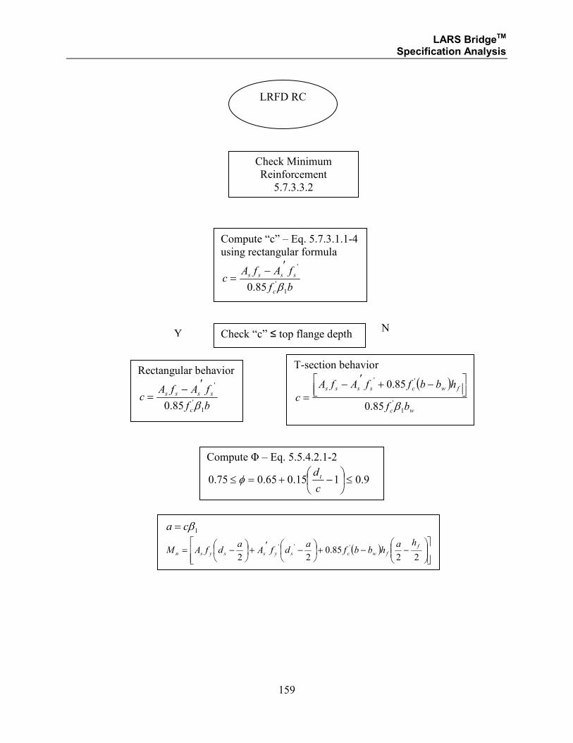
LARS BridgeTM Specification Analysis
159
Check Minimum
Reinforcement
5.7.3.3.2
Compute “c” – Eq. 5.7.3.1.1-4
using rectangular formula
bf
fAfAc
c
ssss
1
'
'
85.0 β
′−=
Check “c” ≤ top flange depth
Compute Φ – Eq. 5.5.4.2.1-2
9.0115.065.075.0 ≤
−+=≤
c
d tφ
Rectangular behavior
bf
fAfAc
c
ssss
1
'
'
85.0 β
′−=
T-section behavior
( )
wc
fwcssss
bf
hbbffAfA
c1
'
''
85.0
85.0
β
−+′−
=
Y N
1βca =
( )
−−+
−′+
−=22
85.022
''' f
fwcsyssysn
hahbbf
adfA
adfAM
LRFD RC
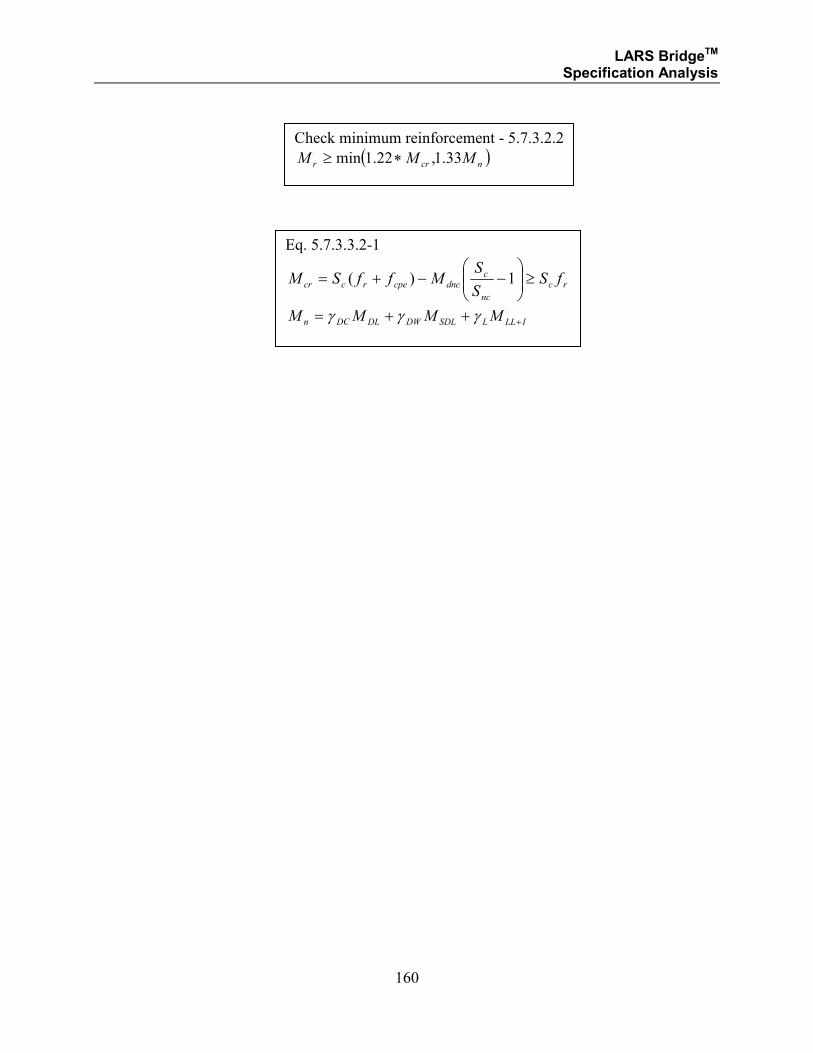
LARS BridgeTM Specification Analysis
160
Check minimum reinforcement - 5.7.3.2.2
( )ncrr MMM 33.1,22.1min ∗≥
Eq. 5.7.3.3.2-1
rc
nc
cdnccperccr fS
S
SMffSM ≥
−−+= 1)(
ILLLSDLDWDLDCn MMMM +++= γγγ
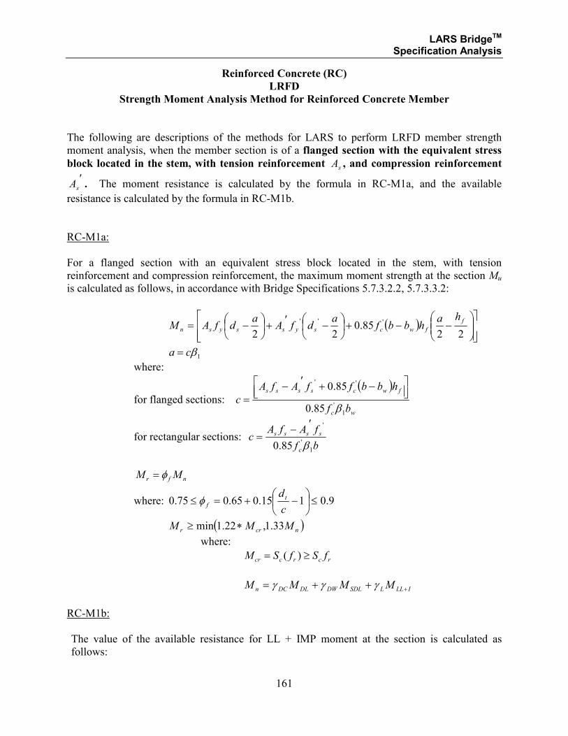
LARS BridgeTM Specification Analysis
161
Reinforced Concrete (RC)
LRFD
Strength Moment Analysis Method for Reinforced Concrete Member
The following are descriptions of the methods for LARS to perform LRFD member strength
moment analysis, when the member section is of a flanged section with the equivalent stress
block located in the stem, with tension reinforcement As , and compression reinforcement
As
′. The moment resistance is calculated by the formula in RC-M1a, and the available
resistance is calculated by the formula in RC-M1b.
RC-M1a:
For a flanged section with an equivalent stress block located in the stem, with tension
reinforcement and compression reinforcement, the maximum moment strength at the section Mu
is calculated as follows, in accordance with Bridge Specifications 5.7.3.2.2, 5.7.3.3.2:
( )
−−+
−′+
−=22
85.022
''' f
fwcsyssysn
hahbbf
adfA
adfAM
1βca =
where:
for flanged sections:
( )
wc
fwcssss
bf
hbbffAfA
c1
'
''
85.0
85.0
β
−+′−
=
for rectangular sections: bf
fAfAc
c
ssss
1
'
'
85.0 β
′−=
nfr MM φ=
where: 9.0115.065.075.0 ≤
−+=≤
c
d tfφ
( )ncrr MMM 33.1,22.1min ∗≥
where:
rcrccr fSfSM ≥= )(
ILLLSDLDWDLDCn MMMM +++= γγγ
RC-M1b:
The value of the available resistance for LL + IMP moment at the section is calculated as
follows:
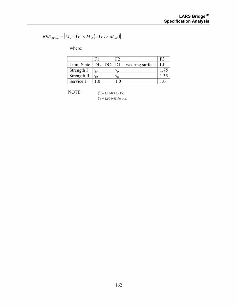
LARS BridgeTM Specification Analysis
162
( ) ( )[ ]sdldlrAVAIL MFMFMRES ×±×±= 21
where:
F1 F2 F3
Limit State DL - DC DL – wearing surface LL
Strength I γp γp 1.75
Strength II γp γp 1.35
Service I 1.0 1.0 1.0
NOTE: γp = 1.25-0.9 for DC γp = 1.50-0.65 for w.s.
LARS BridgeTM Specification Analysis
SECTION 2.2.2
REINFORCED CONCRETE
LOAD RESISTANCE DESIGN METHOD
STRENGTH SHEAR ANALYSIS
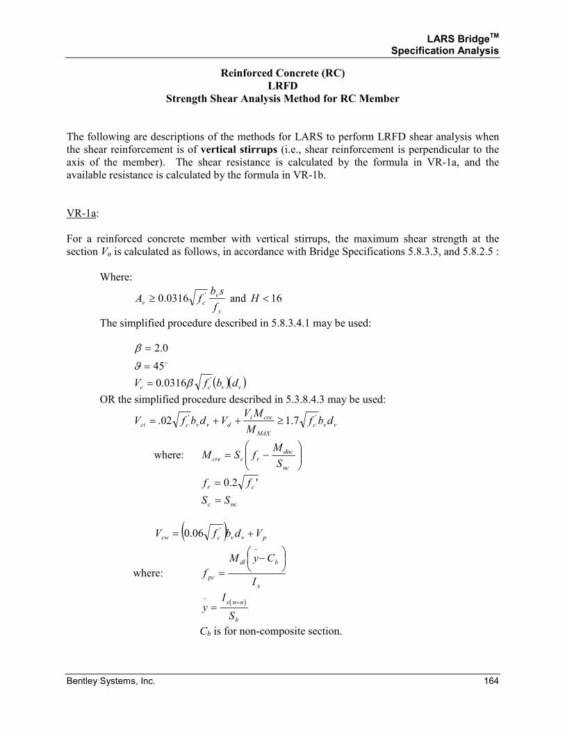
LARS BridgeTM Specification Analysis
Bentley Systems, Inc. 164
Reinforced Concrete (RC)
LRFD
Strength Shear Analysis Method for RC Member
The following are descriptions of the methods for LARS to perform LRFD shear analysis when
the shear reinforcement is of vertical stirrups (i.e., shear reinforcement is perpendicular to the
axis of the member). The shear resistance is calculated by the formula in VR-1a, and the
available resistance is calculated by the formula in VR-1b.
VR-1a:
For a reinforced concrete member with vertical stirrups, the maximum shear strength at the
section Vn is calculated as follows, in accordance with Bridge Specifications 5.8.3.3, and 5.8.2.5 :
Where:
y
v
cvf
sbfA '0316.0≥ and 16<H
The simplified procedure described in 5.8.3.4.1 may be used:
o45
0.2
=
=
ϑ
β
( )( )vvcc dbfV '0316.0 β=
OR the simplified procedure described in 5.3.8.4.3 may be used:
vvc
MAX
crei
dvvcci dbfM
MVVdbfV '' 7.102. ≥++=
where:
−=
nc
dnc
rccreS
MfSM
'2.0 cr ff =
ncc SS =
( ) pvvccw VdbfV += '06.0
where: x
bdl
pcI
CyM
f
−
=
−
( )
yI
S
x n n
b
− ==
Cb is for non-composite section.
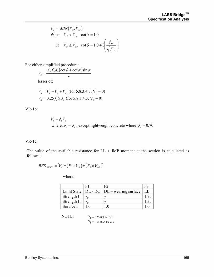
LARS BridgeTM Specification Analysis
Bentley Systems, Inc. 165
( )V MIN V Vc ci cw= ,
When 0.1cot =< ϑcwci VV
Or
+=≥
c
pc
cwcif
fVV
'30.1cotϑ
For either simplified procedure:
( )s
dfAV
vyv
s
ααϑ sincotcot +=
lesser of:
pscn VVVV ++= (for 5.8.3.4.3, Vp = 0)
vvcn dbfV '25.0= (for 5.8.3.4.3, Vp = 0)
VR-1b:
nvr VV φ=
where: fv φφ = , except lightweight concrete where 70.0=vφ
VR-1c:
The value of the available resistance for LL + IMP moment at the section is calculated as
follows:
( ) ( )[ ]sdldlrAVAIL VFVFVRES ×±×±= 21
where:
F1 F2 F3
Limit State DL - DC DL – wearing surface LL
Strength I γp γp 1.75
Strength II γp γp 1.35
Service I 1.0 1.0 1.0
NOTE: γp = 1.25-0.9 for DC γp = 1.50-0.65 for w.s.

LARS BridgeTM Specification Analysis
Bentley Systems, Inc. 166
SECTION 2.2.3
REINFORCED CONCRETE
LOAD RESISTANCE DESIGN METHOD
SERVICE ANALYSIS
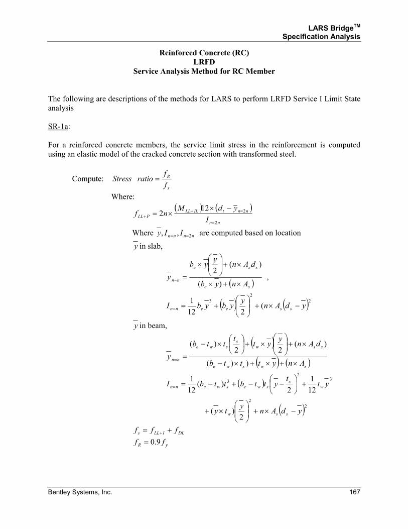
LARS BridgeTM Specification Analysis
Bentley Systems, Inc. 167
Reinforced Concrete (RC)
LRFD
Service Analysis Method for RC Member
The following are descriptions of the methods for LARS to perform LRFD Service I Limit State
analysis
SR-1a:
For a reinforced concrete members, the service limit stress in the reinforcement is computed
using an elastic model of the cracked concrete section with transformed steel.
Compute: s
R
f
fratioStress =
Where:
( ) ( )nn
nntILLL
PLLI
ydMnf
2
2122
=
=++
−××=
Where nnnn IIy 2,, == are computed based on location
y in slab,
( )se
sse
nnAnyb
dAny
yb
y×+×
×+
×
==)(
)(2
,
( ) ( )22
3
(212
1ydAn
yybybI sseenn −×+
+==
y in beam,
( )( ) ( )swswe
ssw
s
swe
nnAnytttb
dAny
ytt
ttb
y×+×+×−
×+
×+
×−
==))(
)(22
)(
( )
( )22
32
3
2)(
12
1
2)(
12
1
ydAny
ty
ytt
yttbttbI
ssw
w
s
sweswenn
−×+
×+
+
−−+−==
DLILLs fff += +
yR ff 9.0=
LARS BridgeTM Specification Analysis
Bentley Systems, Inc. 168
NOTE: When the stress ratio is less than 1, the rating factor is the value of the stress
ratio

LARS BridgeTM Specification Analysis
Bentley Systems, Inc. 169
SECTION 3
PRESTRESSED CONCRETE
AND
COMPOSITE PRESTRESSED CONCRETE
LARS BridgeTM Specification Analysis
Bentley Systems, Inc. 170
Prestressed Concrete (PSC)3
a = Depth of compression block.
alow = Distance from centroid of prestressing steel to lowest strand.
A = Area of prestressed concrete beam.
As = Area of non-prestressed tension reinforcement (Article 9.19).
Asf = Steel area required to develop the compressive strength of the overhanging
portions of the flange (Article 9.17).
Asr = Steel area required to develop the compressive strength of the web of a flanged
member section (Articles 9.17 - 9.19).
As
' = Area of compression reinforcement (Article 9.19).
As
* = Area of prestressing steel (Article 9.17).
ASL = Area of slab reinforcement.
Av = Area of web reinforcement (Article 9.20).
b = Width of flange of flanged member or width of rectangular member.
b′ = Width of a web of a flanged member.
bSLAB = Effective width of the slab.
bTOPFLG = Width of top flange of the concrete section.
bWEB = b′
c = Distance to the neutral axis from the top of the section.
C = Total compressive force in the section.
CAPAVAIL = Available moment capacity of the section.
C1 = Equivalent compressive force to develop rectangular portion of the section.
3 Selected symbols and references are based on AASHTO Standard Specifications for Highway Bridges, Sixteenth
Edition, while other symbols and references are unique to LARS.
LARS BridgeTM Specification Analysis
Bentley Systems, Inc. 171
C2 = Equivalent compressive force to develop overhung flanges of the section.
d = Distance from extreme compressive fiber to centroid of the prestressing force.
d′ = Distance of the centroid of slab reinforcement from the top of the section.
dt = Distance from the extreme compressive fiber to the centroid of the non-
prestressed tension reinforcement (Articles 9.17 - 9.19).
dSL = Distance from centroid of slab reinforcement to bottom of section.
e = ec
ec = Distance to centroid of PS/C beam from centroid of prestressing force.
Ec = Strain at extreme compression fiber.
fc' = Compressive strength of concrete at 28 days.
fcSLAB'
= fc'of the slab.
fd = Stress due to unfactored dead load, at extreme fiber of section when tensile stress
is caused by externally applied loads (Article 9.20).
fpc = Compressive stress in concrete (after allowance for all prestress losses) at centroid
of cross section resisting externally applied loads or at junction of web and flange
when the centroid lies within the flange. (In a composite member, fpc is resultant
compressive stress at centroid of composite section, or at junction of web and
flange when the centroid lies within the flange, due to both prestress and moments
resisted by precast member acting alone.) (Article 9.20)
fpe = Compressive stress in concrete due to effective prestress forces only (after
allowance for all prestress losses) at extreme fiber of section where tensile stress
is caused by externally applied loads (Article 9.20).
f s' = Ultimate stress of prestressing steel (Articles 9.15 and 9.17).
f su* = Average stress in prestressing steel at ultimate load.
fsy = Yield stress of non-prestressed conventional reinforcement in tension (Articles
9.19 and 9.20).
f sy' = f y
'
fsySLAB = Yield stress of slab reinforcement.
LARS BridgeTM Specification Analysis
Bentley Systems, Inc. 172
f y' = Yield stress of non-prestressed conventional reinforcement (Article 9.19).
F = Factor of rating type (inventory, operating, posting, etc.)
Ff = Final prestressing force.
Min = Minimum
Mcr = Moment causing flexural cracking at section due to externally applied loads
(Article 9.20).
Mcr
* = Cracking moment (Article 9.18).
Mdl = Dead load moment at the section.
Msdl = Superimposed dead load moment at the section.
Mu = Factored moment at section ≤ φ Mn (Articles 9.17 and 9.18).
MMAX = Maximum total moment at the section.
p = As/bdt, ratio of non-prestressed tension reinforcement (Articles 9.17 - 9.19).
pSL = ASL/db, ratio of slab reinforcement.
p′ = As′ /bd, ratio of compression reinforcement (Article 9.19).
p* = As*/bd, ratio of prestressing steel (Articles 9.17 and 9.19).
S = Section modulus of the section.
Sb
+ = Section modulus at bottom fiber of the section for positive bending moment.
Sb
− = Section modulus at bottom fiber of the section for negative bending moment.
St
+ = Section modulus at top fiber of the section for positive bending moment.
St
_ = Section modulus at top fiber of the section for negative bending moment.
SMCAP = Serviceability moment capacity.
t = Average thickness of the flange of a flanged member (Articles 9.17 and 9.18).
tBOTFLG = Thickness of bottom flange of the concrete section.
LARS BridgeTM Specification Analysis
Bentley Systems, Inc. 173
T = Total tension force in a section.
T1 = Equivalent tension force to develop rectangular portion of the section.
T2 = Equivalent tension force to develop overhung portion of the section.
Vc = Nominal shear strength provided by concrete (Article 9.20).
Vci = Nominal shear strength provided by concrete when diagonal cracking results from
combined shear and moment (Article 9.20).
Vcw = Nominal shear strength provided by concrete when diagonal cracking results from
excessive principal tensile stress in web (Article 9.20).
Vd = Shear force at section due to unfactored dead load (Article 9.20).
Vi = Factored shear force at section due to externally applied loads occurring
simultaneously with Mmax (Article 9.20).
Vp = Vertical component of effective prestress force at section (Article 9.20).
Vs = Nominal shear strength provided by shear reinforcement (Article 9.20).
Vu = Factored shear force at section (Article 9.20).
VAVAIL = Available shear capacity for Live Load + Impact.
VDL = Dead load shear at the section.
VSDL = Superimposed dead load shear at the section.
Yt = Distance from centroidal axis of gross section, neglecting reinforcement, to
extreme fiber in tension (Article 9.20).
Z = Equivalent section modulus.
β 1 = Factor for concrete strength as defined in Article 8.16.2.7 (Articles 9.17 - 9.19).
β 1 = 0.85 for f psc
' ≤ 4000
β 1 =0.85-(0.05) ( )f c' / .− ≥4000 1000 0 65
LARS BridgeTM Specification Analysis
Bentley Systems, Inc. 174
Prestressed Concrete (PSC) and Composite Prestressed Concrete (CPS)
The various criteria logic that is used to determine the calculation methods for the above listed
conditions are referenced below by number. The calculation methods and formulae are
referenced by number.
ASD
The elastic stresses are checked to satisfy the Allowable Stress Design method.
LFD
Non-Composite:
A section will be considered as non-composite if the member is designated as PSC, or if the
member is designated as CPS, but the section is located in a range designated as non-composite.
1. Rectangular Section Analysis, PSC
The values for non-composite moment capacity and for available capacity for LL
+ IMP are calculated by the formulae PS-M1a and PS-M1b to PS-M3a and PS-
M3b, depending upon whether a section has tension and/or compression non-
prestressed reinforcing steel and whether the reinforcing index is ≤ β1.
2. I-Shape Section Analysis, PSC
The values for non-composite moment capacity and for available capacity for LL
+ IMP are calculated by the formulae PS-M4a and PS-M4b to PS-M9a and PS-
M9b, depending upon whether a section has tension and/or compression non-
prestressed reinforcing steel, the depth of the compression stress block is greater
or less than the I section flange and whether the reinforcing index is ≤ β1.
Composite:
A section will be considered as composite if the member is designated as CPS, and the section is
located in a range designated as composite.
1. I-Shape Section Analysis, PSC
The values for non-composite moment capacity and for available capacity for LL
+ IMP are calculated by the formulae CP-M1a and CP-M1b to CP-M6a and CP-
M6b, depending upon whether a section has tension and/or compression non-
prestressed reinforcing steel, the depth of the compression stress block is greater
or less than the I section flange and whether the reinforcing index is ≤ β1.
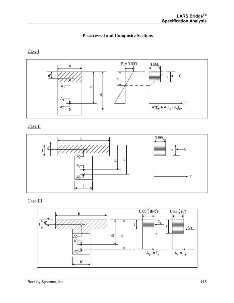
LARS BridgeTM Specification Analysis
Bentley Systems, Inc. 175
Prestressed and Composite Sections
Case I
Case II
Case III
LARS BridgeTM Specification Analysis
Bentley Systems, Inc. 176
SECTION 3.1
PRESTRESSED CONCRETE
AND
COMPOSITE PRESTRESSED CONCRETE
ALLOWABLE STRESS DESIGN AND LOAD FACTOR DESIGN METHODS
LARS BridgeTM Specification Analysis
Bentley Systems, Inc. 177
SECTION 3.1.1
PRESTRESSED CONCRETE
AND
COMPOSITE PRESTRESSED CONCRETE
ALLOWABLE STRESS DESIGN AND LOAD FACTOR DESIGN METHOD
MOMENT ANALYSIS
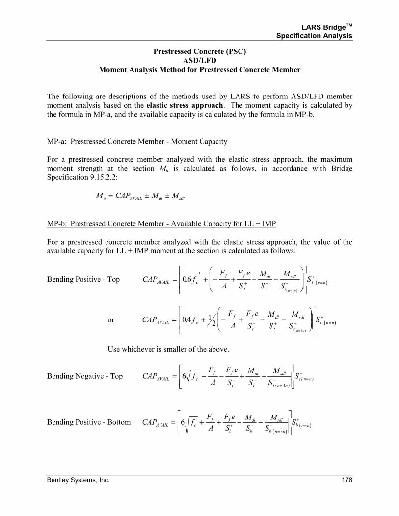
LARS BridgeTM Specification Analysis
Bentley Systems, Inc. 178
Prestressed Concrete (PSC)
ASD/LFD
Moment Analysis Method for Prestressed Concrete Member
The following are descriptions of the methods used by LARS to perform ASD/LFD member
moment analysis based on the elastic stress approach. The moment capacity is calculated by
the formula in MP-a, and the available capacity is calculated by the formula in MP-b.
MP-a: Prestressed Concrete Member - Moment Capacity
For a prestressed concrete member analyzed with the elastic stress approach, the maximum
moment strength at the section Mu is calculated as follows, in accordance with Bridge
Specification 9.15.2.2:
M CAP M Mu AVAIL dl sdl= ± ±
MP-b: Prestressed Concrete Member - Available Capacity for LL + IMP
For a prestressed concrete member analyzed with the elastic stress approach, the value of the
available capacity for LL + IMP moment at the section is calculated as follows:
Bending Positive - Top
( )
( )CAP fF
A
F e
S
M
S
M
SSAVAIL c
f f
t
dl
t
sdl
t
t n n
n n
= ′ + − + − −
+ + +
+=
=
06
3
.
or
( )
( )CAP fF
A
F e
S
M
S
M
SSAVAIL c
f f
t
dl
t
sdl
t
t n n
n n
= + − + − −
+ + +
+=
=
04 12
3
. '
Use whichever is smaller of the above.
Bending Negative - Top CAP fF
A
F e
S
M
S
M
SSAVAIL c
f f
t
dl
t
sdl
t n n
t n n= + − + +
− −=
− =−6
3
'
( )
( )
Bending Positive - Bottom ( )
( )CAP fF
A
F e
S
M
S
M
SSAVAIL c
f f
b
dl
b
sdl
b n n
b n n= + + − −
+ + +=
+=6
3
'
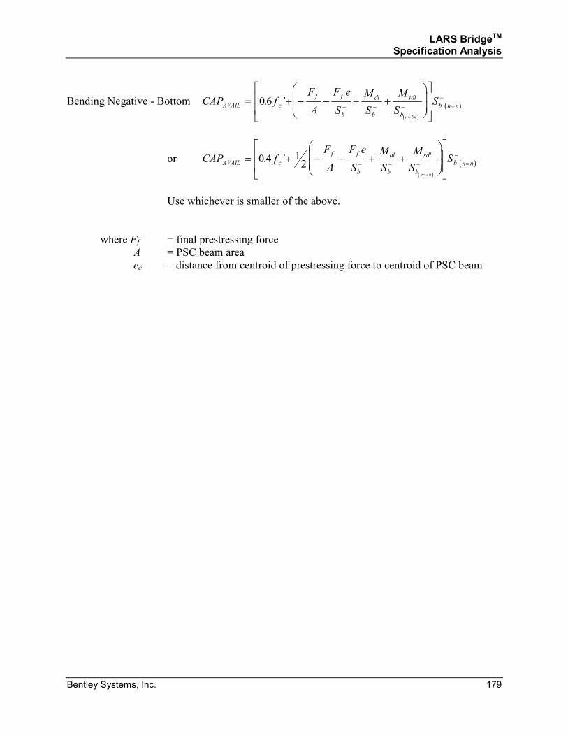
LARS BridgeTM Specification Analysis
Bentley Systems, Inc. 179
Bending Negative - Bottom
( )
( )CAP fF
A
F e
S
M
S
M
SSAVAIL c
f f
b
dl
b
sdl
b
b n n
n n
= + − − + +
− − −
−=
=
06
3
. '
or
( )
( )CAP fF
A
F e
S
M
S
M
SSAVAIL c
f f
b
dl
b
sdl
b
b n n
n n
= + − − + +
− − −
−=
=
0 4 12
3
. '
Use whichever is smaller of the above.
where Ff = final prestressing force
A = PSC beam area
ec = distance from centroid of prestressing force to centroid of PSC beam
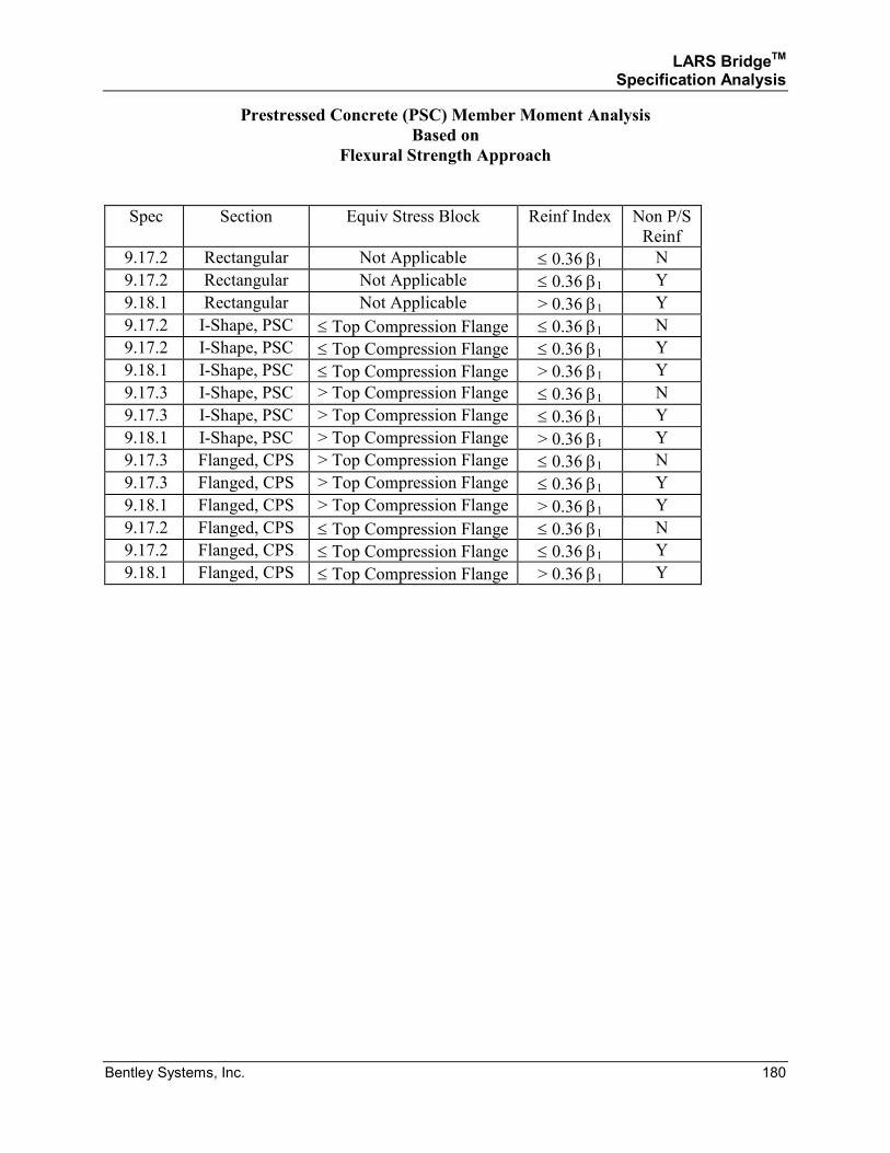
LARS BridgeTM Specification Analysis
Bentley Systems, Inc. 180
Prestressed Concrete (PSC) Member Moment Analysis
Based on
Flexural Strength Approach
Spec Section Equiv Stress Block Reinf Index Non P/S
Reinf
9.17.2 Rectangular Not Applicable ≤ 0.36 β1 N
9.17.2 Rectangular Not Applicable ≤ 0.36 β1 Y
9.18.1 Rectangular Not Applicable > 0.36 β1 Y
9.17.2 I-Shape, PSC ≤ Top Compression Flange ≤ 0.36 β1 N
9.17.2 I-Shape, PSC ≤ Top Compression Flange ≤ 0.36 β1 Y
9.18.1 I-Shape, PSC ≤ Top Compression Flange > 0.36 β1 Y
9.17.3 I-Shape, PSC > Top Compression Flange ≤ 0.36 β1 N
9.17.3 I-Shape, PSC > Top Compression Flange ≤ 0.36 β1 Y
9.18.1 I-Shape, PSC > Top Compression Flange > 0.36 β1 Y
9.17.3 Flanged, CPS > Top Compression Flange ≤ 0.36 β1 N
9.17.3 Flanged, CPS > Top Compression Flange ≤ 0.36 β1 Y
9.18.1 Flanged, CPS > Top Compression Flange > 0.36 β1 Y
9.17.2 Flanged, CPS ≤ Top Compression Flange ≤ 0.36 β1 N
9.17.2 Flanged, CPS ≤ Top Compression Flange ≤ 0.36 β1 Y
9.18.1 Flanged, CPS ≤ Top Compression Flange > 0.36 β1 Y
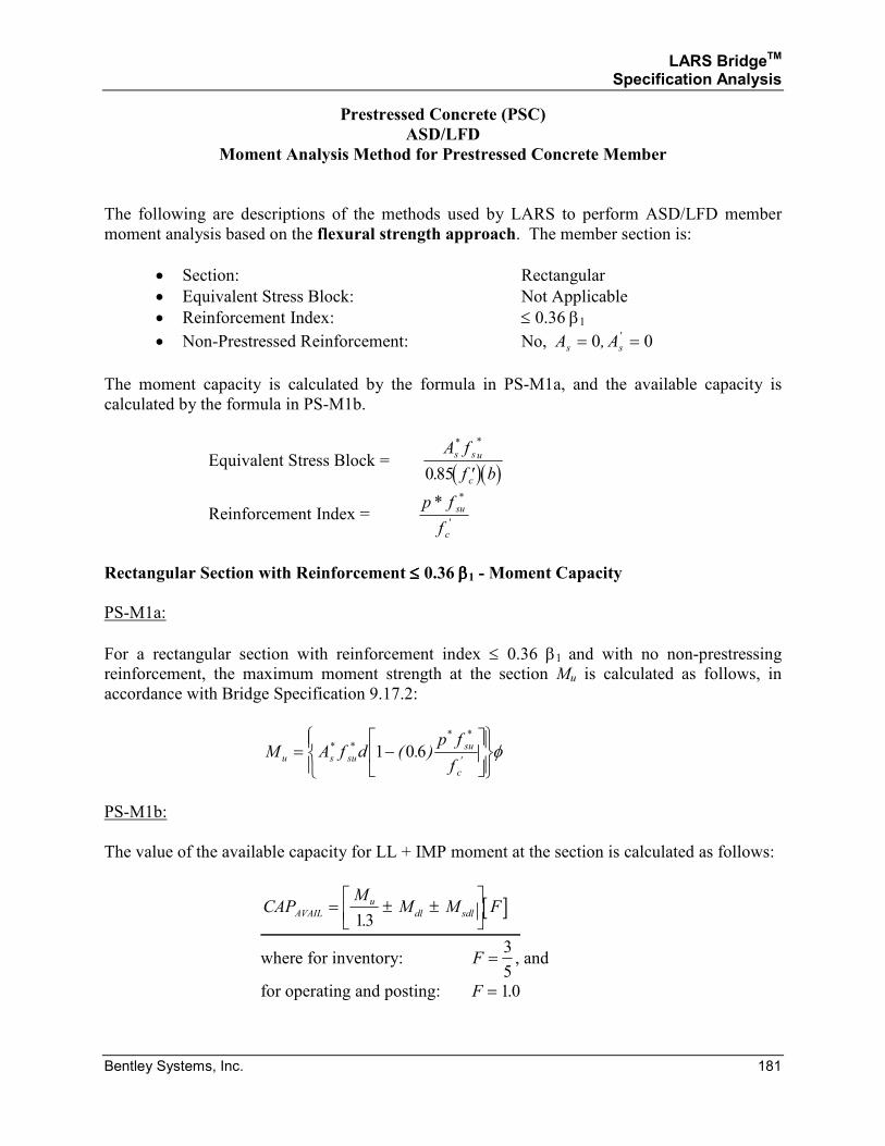
LARS BridgeTM Specification Analysis
Bentley Systems, Inc. 181
Prestressed Concrete (PSC)
ASD/LFD
Moment Analysis Method for Prestressed Concrete Member
The following are descriptions of the methods used by LARS to perform ASD/LFD member
moment analysis based on the flexural strength approach. The member section is:
• Section: Rectangular
• Equivalent Stress Block: Not Applicable
• Reinforcement Index: ≤ 0.36 β1
• Non-Prestressed Reinforcement: No, A As s= =0 0, '
The moment capacity is calculated by the formula in PS-M1a, and the available capacity is
calculated by the formula in PS-M1b.
Equivalent Stress Block = ( )( )A f
f b
s s u
c
* *
.0 85 ′
Reinforcement Index = p f
f
su
c
* *
'
Rectangular Section with Reinforcement ≤≤≤≤ 0.36 ββββ1 - Moment Capacity
PS-M1a:
For a rectangular section with reinforcement index ≤ 0.36 β1 and with no non-prestressing
reinforcement, the maximum moment strength at the section Mu is calculated as follows, in
accordance with Bridge Specification 9.17.2:
M A f dp f
fu s su
su
c
= −
* *
* *
'( . )1 0 6 φ
PS-M1b:
The value of the available capacity for LL + IMP moment at the section is calculated as follows:
[ ]CAPM
M M FAVAIL
u
dl sdl= ± ±
13.
where for inventory: F =3
5, and
for operating and posting: F = 10.
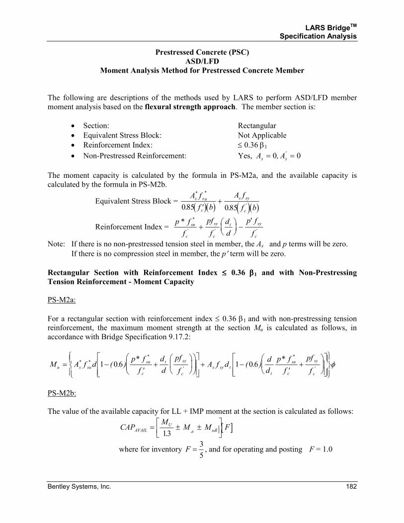
LARS BridgeTM Specification Analysis
Bentley Systems, Inc. 182
Prestressed Concrete (PSC)
ASD/LFD
Moment Analysis Method for Prestressed Concrete Member
The following are descriptions of the methods used by LARS to perform ASD/LFD member
moment analysis based on the flexural strength approach. The member section is:
• Section: Rectangular
• Equivalent Stress Block: Not Applicable
• Reinforcement Index: ≤ 0.36 β1
• Non-Prestressed Reinforcement: Yes, A As s= =0 0, '
The moment capacity is calculated by the formula in PS-M2a, and the available capacity is
calculated by the formula in PS-M2b.
Equivalent Stress Block = ( )( ) ( )( )A f
f b
A f
f b
s su
c
s sy
c
* *
'. .085 085′+
Reinforcement Index = p f
f
pf
f
d
d
p f
f
su
c
sy
c
t sy
c
* '*
' ' '+
−
Note: If there is no non-prestressed tension steel in member, the As and p terms will be zero.
If there is no compression steel in member, the p′ term will be zero.
Rectangular Section with Reinforcement Index ≤≤≤≤ 0.36 ββββ1 and with Non-Prestressing Tension Reinforcement - Moment Capacity
PS-M2a:
For a rectangular section with reinforcement index ≤ 0.36 β1 and with non-prestressing tension
reinforcement, the maximum moment strength at the section Mu is calculated as follows, in
accordance with Bridge Specification 9.17.2:
M A f dp f
f
d
d
pf
fA f d
d
d
p f
f
pf
fu s su
su
c
t sy
c
s sy t
t
su
c
sy
c
= −′
+
+ −
′+
* *
*
'
*
'( . )
*( . )
*1 0 6 1 0 6 φ
PS-M2b:
The value of the available capacity for LL + IMP moment at the section is calculated as follows:
[ ]CAPM
M M FAVAIL
U
sdldl= ± ±
13.
where for inventory F =3
5, and for operating and posting F = 1.0
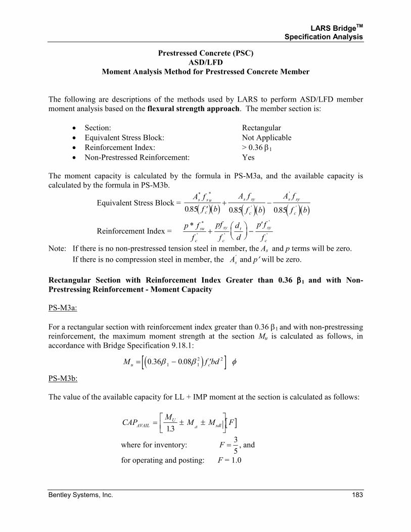
LARS BridgeTM Specification Analysis
Bentley Systems, Inc. 183
Prestressed Concrete (PSC)
ASD/LFD
Moment Analysis Method for Prestressed Concrete Member
The following are descriptions of the methods used by LARS to perform ASD/LFD member
moment analysis based on the flexural strength approach. The member section is:
• Section: Rectangular
• Equivalent Stress Block: Not Applicable
• Reinforcement Index: > 0.36 β1
• Non-Prestressed Reinforcement: Yes
The moment capacity is calculated by the formula in PS-M3a, and the available capacity is
calculated by the formula in PS-M3b.
Equivalent Stress Block = ( )( ) ( )( ) ( )( )
A f
f b
A f
f b
A f
f b
s s u
c
s sy
c
s sy
c
* *
'
'
'. . .085 085 085′+ −
Reinforcement Index = p f
f
pf
f
d
d
p f
f
su
c
sy
c
t sy
c
* *
' '
'
'+
−
′
Note: If there is no non-prestressed tension steel in member, the As and p terms will be zero.
If there is no compression steel in member, the As
' and p′ will be zero.
Rectangular Section with Reinforcement Index Greater than 0.36 ββββ1 and with Non- Prestressing Reinforcement - Moment Capacity
PS-M3a:
For a rectangular section with reinforcement index greater than 0.36 β1 and with non-prestressing
reinforcement, the maximum moment strength at the section Mu is calculated as follows, in
accordance with Bridge Specification 9.18.1:
( )[ ]M f bdu c= − ′0 36 0 081 1
2 2. .β β φ
PS-M3b:
The value of the available capacity for LL + IMP moment at the section is calculated as follows:
[ ]CAPM
M M FAVAIL
U
sdldl= ± ±
13.
where for inventory: F =3
5, and
for operating and posting: F = 1.0
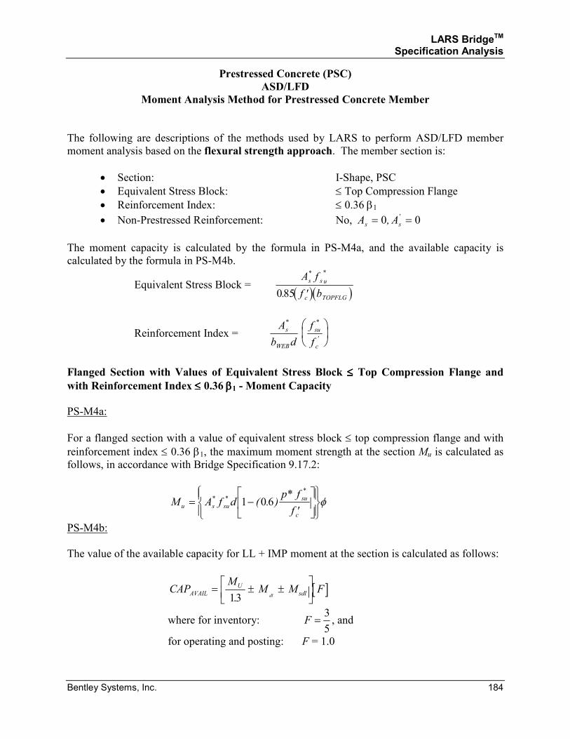
LARS BridgeTM Specification Analysis
Bentley Systems, Inc. 184
Prestressed Concrete (PSC)
ASD/LFD
Moment Analysis Method for Prestressed Concrete Member
The following are descriptions of the methods used by LARS to perform ASD/LFD member
moment analysis based on the flexural strength approach. The member section is:
• Section: I-Shape, PSC
• Equivalent Stress Block: ≤ Top Compression Flange
• Reinforcement Index: ≤ 0.36 β1
• Non-Prestressed Reinforcement: No, A As s= =0 0, '
The moment capacity is calculated by the formula in PS-M4a, and the available capacity is
calculated by the formula in PS-M4b.
Equivalent Stress Block = ( )( )A f
f b
s s u
c TOPFLG
* *
.085 ′
Reinforcement Index = A
b d
s
WEB
* f
f
su
c
*
'
Flanged Section with Values of Equivalent Stress Block ≤≤≤≤ Top Compression Flange and with Reinforcement Index ≤≤≤≤ 0.36 ββββ1 - Moment Capacity
PS-M4a:
For a flanged section with a value of equivalent stress block ≤ top compression flange and with
reinforcement index ≤ 0.36 β1, the maximum moment strength at the section Mu is calculated as
follows, in accordance with Bridge Specification 9.17.2:
M A f dp f
fu s su
su
c
= −′
* *
*
( . )*
1 0 6 φ
PS-M4b:
The value of the available capacity for LL + IMP moment at the section is calculated as follows:
[ ]CAPM
M M FAVAIL
U
sdldl= ± ±
13.
where for inventory: F =3
5, and
for operating and posting: F = 1.0
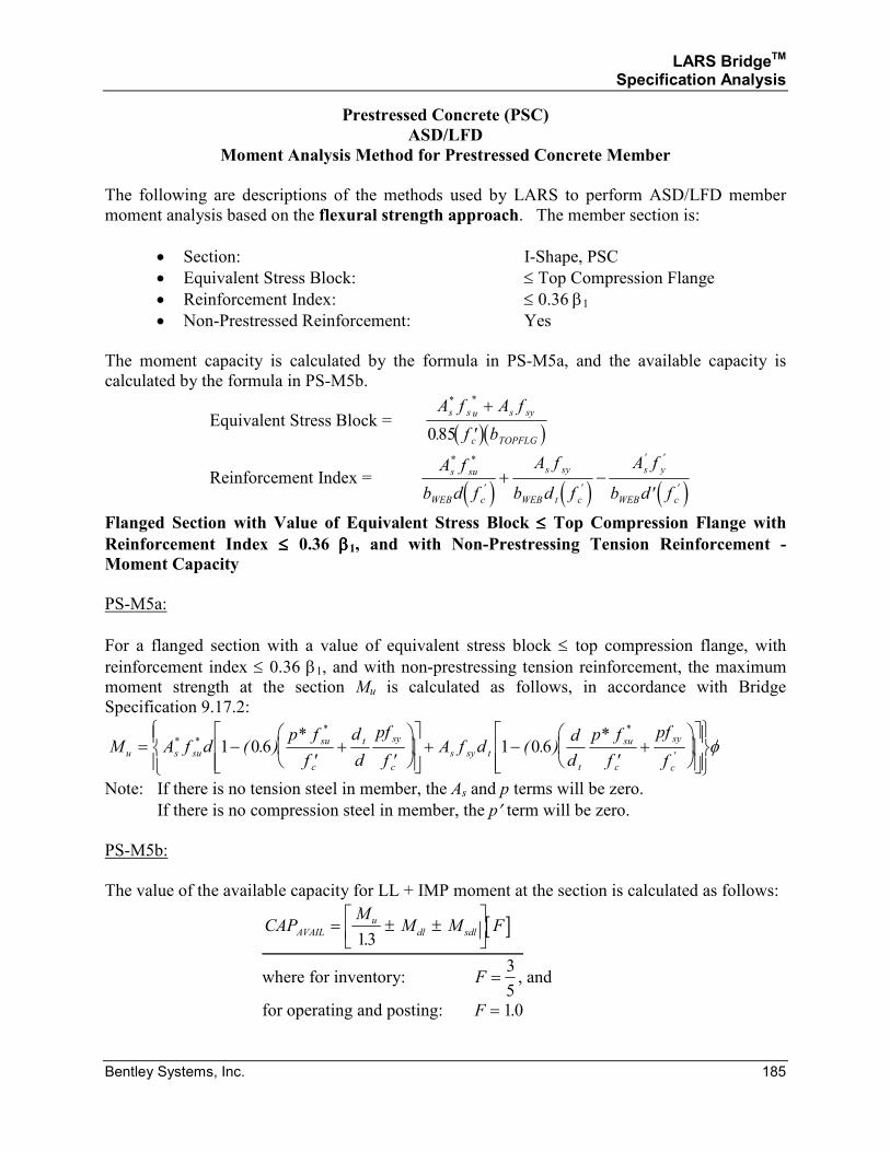
LARS BridgeTM Specification Analysis
Bentley Systems, Inc. 185
Prestressed Concrete (PSC)
ASD/LFD
Moment Analysis Method for Prestressed Concrete Member
The following are descriptions of the methods used by LARS to perform ASD/LFD member
moment analysis based on the flexural strength approach. The member section is:
• Section: I-Shape, PSC
• Equivalent Stress Block: ≤ Top Compression Flange
• Reinforcement Index: ≤ 0.36 β1
• Non-Prestressed Reinforcement: Yes
The moment capacity is calculated by the formula in PS-M5a, and the available capacity is
calculated by the formula in PS-M5b.
Equivalent Stress Block = ( )( )
A f A f
f b
s s u s sy
c TOPFLG
* *
.
+
′085
Reinforcement Index = ( ) ( ) ( )
A f
b d f
A f
b d f
A f
b d f
s su
WEB c
s sy
WEB t c
s y
WEB c
* *
' '
' '
'+ −
′
Flanged Section with Value of Equivalent Stress Block ≤≤≤≤ Top Compression Flange with Reinforcement Index ≤≤≤≤ 0.36 ββββ1, and with Non-Prestressing Tension Reinforcement - Moment Capacity
PS-M5a:
For a flanged section with a value of equivalent stress block ≤ top compression flange, with
reinforcement index ≤ 0.36 β1, and with non-prestressing tension reinforcement, the maximum
moment strength at the section Mu is calculated as follows, in accordance with Bridge
Specification 9.17.2:
M A f dp f
f
d
d
pf
fA f d
d
d
p f
f
pf
fu s su
su
c
t sy
c
s sy t
t
su
c
sy
c
= −′
+′
+ −
′+
* *
* *
'( . )
*( . )
*1 0 6 1 0 6 φ
Note: If there is no tension steel in member, the As and p terms will be zero.
If there is no compression steel in member, the p′ term will be zero.
PS-M5b:
The value of the available capacity for LL + IMP moment at the section is calculated as follows:
[ ]CAPM
M M FAVAIL
u
dl sdl= ± ±
13.
where for inventory: F =3
5, and
for operating and posting: F = 10.
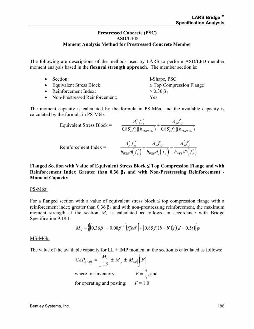
LARS BridgeTM Specification Analysis
Bentley Systems, Inc. 186
Prestressed Concrete (PSC)
ASD/LFD
Moment Analysis Method for Prestressed Concrete Member
The following are descriptions of the methods used by LARS to perform ASD/LFD member
moment analysis based in the flexural strength approach. The member section is:
• Section: I-Shape, PSC
• Equivalent Stress Block: ≤ Top Compression Flange
• Reinforcement Index: > 0.36 β1
• Non-Prestressed Reinforcement: Yes
The moment capacity is calculated by the formula in PS-M6a, and the available capacity is
calculated by the formula in PS-M6b.
Equivalent Stress Block = ( )( ) ( )( )A f
f b
A f
f b
s s u
c TOPFLG
s sy
c TOPFLG
* *
. .085 085′+
′
Reinforcement Index = ( ) ( ) ( )
A f
b d f
A f
b d f
A f
b d f
s su
WEB c
s sy
WEB t c
s y
WEB c
* *
' '
' '
'+ −
′
Flanged Section with Value of Equivalent Stress Block ≤≤≤≤ Top Compression Flange and with Reinforcement Index Greater than 0.36 ββββ1 and with Non-Prestressing Reinforcement - Moment Capacity
PS-M6a:
For a flanged section with a value of equivalent stress block ≤ top compression flange with a
reinforcement index greater than 0.36 β1 and with non-prestressing reinforcement, the maximum
moment strength at the section Mu is calculated as follows, in accordance with Bridge
Specification 9.18.1:
( )[ ] ( )( )( )[ ]{ }φββ tdtbbfdbfM ccu 5.085.008.036.02
11 −′−′+′′−=
MS-M6b:
The value of the available capacity for LL + IMP moment at the section is calculated as follows:
[ ]CAPM
M M FAVAIL
U
sdldl= ± ±
13.
where for inventory: F =3
5, and
for operating and posting: F = 1.0
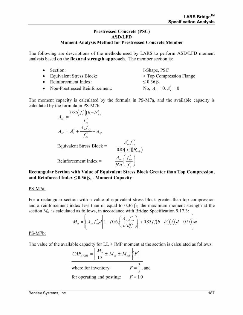
LARS BridgeTM Specification Analysis
Bentley Systems, Inc. 187
Prestressed Concrete (PSC)
ASD/LFD
Moment Analysis Method for Prestressed Concrete Member
The following are descriptions of the methods used by LARS to perform ASD/LFD moment
analysis based on the flexural strength approach. The member section is:
• Section: I-Shape, PSC
• Equivalent Stress Block: > Top Compression Flange
• Reinforcement Index: ≤ 0.36 β1
• Non-Prestressed Reinforcement: No, A As s= =0 0, '
The moment capacity is calculated by the formula in PS-M7a, and the available capacity is
calculated by the formula in PS-M7b.
( )( )
Af b b
fsf
c t
su
=−085. ''
*
A AA f
fAsr s
s sy
su
sf= + −*
*
Equivalent Stress Block = ( )( )A f
f b
sr s u
c web
* *
.085 ′ ′
Reinforcement Index = A
b d
f
f
sr su
c′
*
'
Rectangular Section with Value of Equivalent Stress Block Greater than Top Compression,
and Reinforced Index ≤≤≤≤ 0.36 ββββ1 - Moment Capacity
PS-M7a:
For a rectangular section with a value of equivalent stress block greater than top compression
and a reinforcement index less than or equal to 0.36 β1 the maximum moment strength at the
section Mu is calculated as follows, in accordance with Bridge Specification 9.17.3:
( )( )( )M A f dA f
b dff b b t d tu sr su
sr su
c
c= −′ ′
+ ′ − ′ −
*
*
( . ) . .1 06 085 05 φ
PS-M7b:
The value of the available capacity for LL + IMP moment at the section is calculated as follows:
[ ]CAPM
M M FAVAIL
u
dl sdl= ± ±
13.
where for inventory: F =3
5, and
for operating and posting: F = 10.
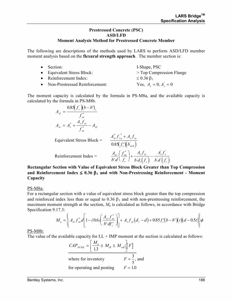
LARS BridgeTM Specification Analysis
Bentley Systems, Inc. 188
Prestressed Concrete (PSC)
ASD/LFD
Moment Analysis Method for Prestressed Concrete Member
The following are descriptions of the methods used by LARS to perform ASD/LFD member
moment analysis based on the flexural strength approach. The member section is:
• Section: I-Shape, PSC
• Equivalent Stress Block: > Top Compression Flange
• Reinforcement Index: ≤ 0.36 β1
• Non-Prestressed Reinforcement: Yes, A As s= =0 0, '
The moment capacity is calculated by the formula in PS-M8a, and the available capacity is
calculated by the formula in PS-M8b.
( )( )
Af b b
fsf
c t
su
=−085. ''
*
A AA f
fAsr s
s sy
su
sf= + −*
*
Equivalent Stress Block = ( )( )
A f A f
f b
sr s u s sy
c web
* *
'.
+
′0 85
Reinforcement Index = ( ) ( )
A
b d
f
f
A f
b d f
A f
b d f
sr su
c
s sy
t c
s y
c′
+ −
*
' ' '
' '
' ' '
Rectangular Section with Value of Equivalent Stress Block Greater than Top Compression
and Reinforcement Index ≤≤≤≤ 0.36 ββββ1 and with Non-Prestressing Reinforcement - Moment Capacity
PS-M8a:
For a rectangular section with a value of equivalent stress block greater than the top compression
and reinforced index less than or equal to 0.36 β1 and with non-prestressing reinforcement, the
maximum moment strength at the section, Mu is calculated as follows, in accordance with Bridge
Specification 9.17.3:
( ) ( )( )( )M A f dA f
b dfA f d d f b b t d tu sr su
sr su
c
s sy t c= −′ ′
+ − + ′ − ′ −
*
*
( . ) . .1 06 085 05 φ
PS-M8b:
The value of the available capacity for LL + IMP moment at the section is calculated as follows:
[ ]CAPM
M M FAVAIL
u
dl sdl= ± ±
13.
where for inventory F =3
5, and
for operating and posting F = 10.
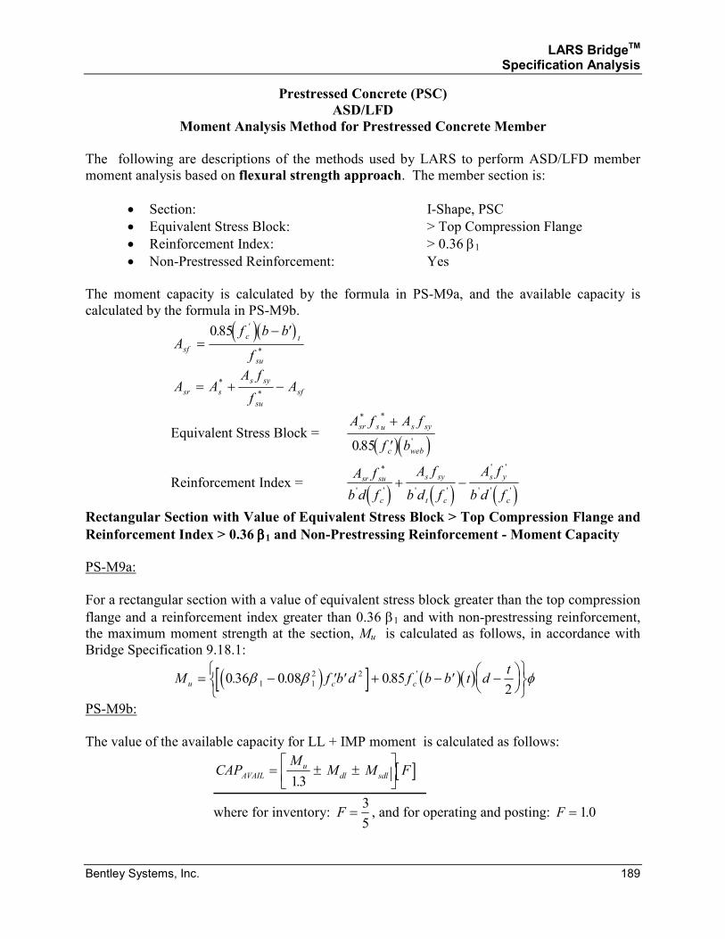
LARS BridgeTM Specification Analysis
Bentley Systems, Inc. 189
Prestressed Concrete (PSC)
ASD/LFD
Moment Analysis Method for Prestressed Concrete Member
The following are descriptions of the methods used by LARS to perform ASD/LFD member
moment analysis based on flexural strength approach. The member section is:
• Section: I-Shape, PSC
• Equivalent Stress Block: > Top Compression Flange
• Reinforcement Index: > 0.36 β1
• Non-Prestressed Reinforcement: Yes
The moment capacity is calculated by the formula in PS-M9a, and the available capacity is
calculated by the formula in PS-M9b.
( )( )
Af b b
fsf
c t
su
=−085. ''
*
A AA f
fAsr s
s sy
su
sf= + −*
*
Equivalent Stress Block = ( )( )
A f A f
f b
sr s u s sy
c web
* *
'.
+
′085
Reinforcement Index = ( ) ( ) ( )
A f
b d f
A f
b d f
A f
b d f
sr su
c
s sy
t c
s y
c
*
' ' ' '
' '
' ' '+ −
Rectangular Section with Value of Equivalent Stress Block > Top Compression Flange and
Reinforcement Index > 0.36 ββββ1 and Non-Prestressing Reinforcement - Moment Capacity
PS-M9a:
For a rectangular section with a value of equivalent stress block greater than the top compression
flange and a reinforcement index greater than 0.36 β1 and with non-prestressing reinforcement,
the maximum moment strength at the section, Mu is calculated as follows, in accordance with
Bridge Specification 9.18.1:
( )[ ] ( )( )M f b d f b b t dt
u c c= − ′ ′ + − ′ −
0 36 0 08 0852
1 1
2 2. . . 'β β φ
PS-M9b:
The value of the available capacity for LL + IMP moment is calculated as follows:
[ ]CAPM
M M FAVAIL
u
dl sdl= ± ±
13.
where for inventory: F =3
5, and for operating and posting: F = 10.
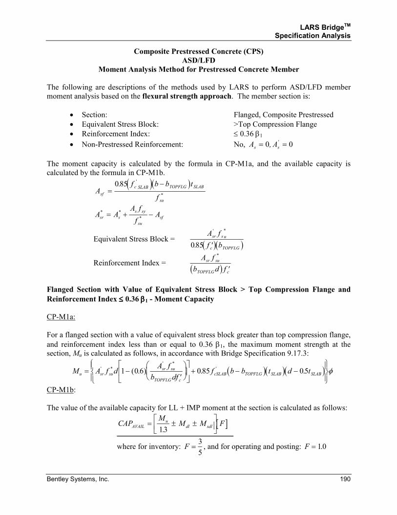
LARS BridgeTM Specification Analysis
Bentley Systems, Inc. 190
Composite Prestressed Concrete (CPS)
ASD/LFD
Moment Analysis Method for Prestressed Concrete Member
The following are descriptions of the methods used by LARS to perform ASD/LFD member
moment analysis based on the flexural strength approach. The member section is:
• Section: Flanged, Composite Prestressed
• Equivalent Stress Block: >Top Compression Flange
• Reinforcement Index: ≤ 0.36 β1
• Non-Prestressed Reinforcement: No, A As s= =0 0, '
The moment capacity is calculated by the formula in CP-M1a, and the available capacity is
calculated by the formula in CP-M1b.
( )( )
Af b b t
fsf
c SLAB TOPFLG SLAB
su
=−085. '
*
A AA f
fAsr s
s sy
su
sf
* *
*= + −
Equivalent Stress Block = ( )( )A f
f b
sr s u
c TOPFLG
' *
.085 ′
Reinforcement Index = ( )
A f
b d f
sr su
TOPFLG c
*
′
Flanged Section with Value of Equivalent Stress Block > Top Compression Flange and
Reinforcement Index ≤≤≤≤ 0.36 ββββ1 - Moment Capacity
CP-M1a:
For a flanged section with a value of equivalent stress block greater than top compression flange,
and reinforcement index less than or equal to 0.36 β1, the maximum moment strength at the
section, Mu is calculated as follows, in accordance with Bridge Specification 9.17.3:
( )( )( )M A f dA f
b dff b b t d tu sr su
sr su
TOPFLG c
cSLAB TOPFLG SLAB SLAB= −′
+ − −
' *
' *
'( . ) . .1 0 6 0 85 05 φ
CP-M1b:
The value of the available capacity for LL + IMP moment at the section is calculated as follows:
[ ]CAPM
M M FAVAIL
u
dl sdl= ± ±
13.
where for inventory: F =3
5, and for operating and posting: F = 10.
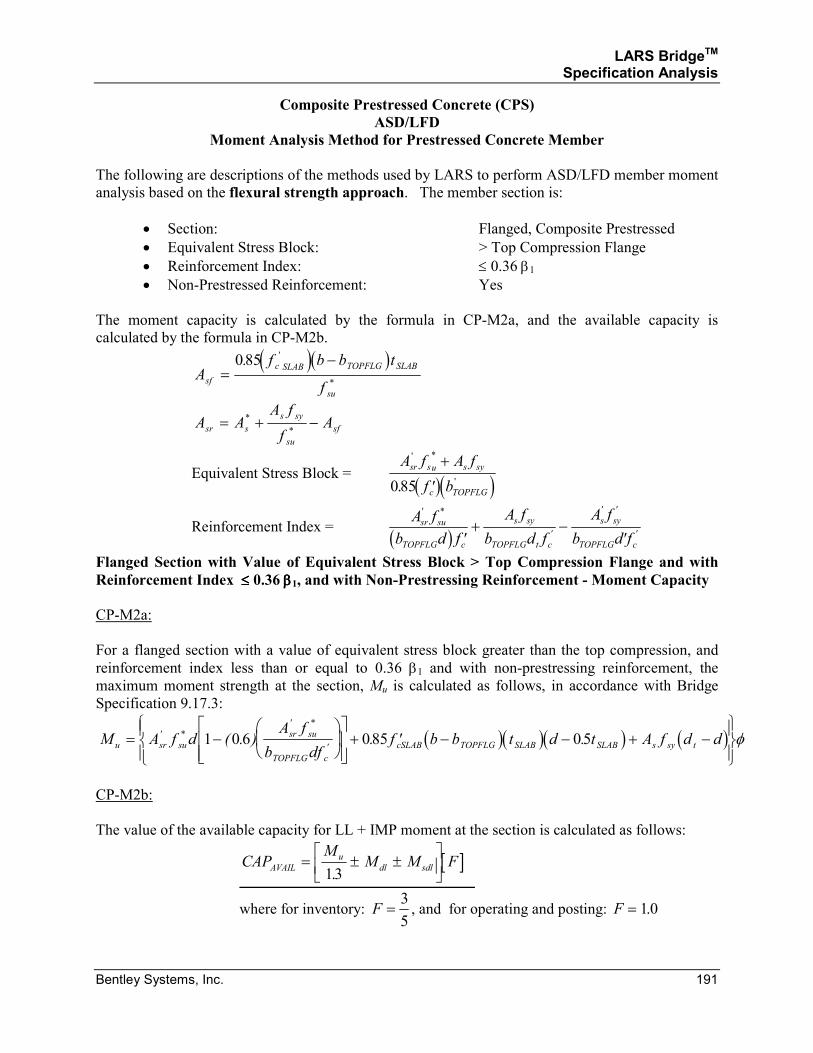
LARS BridgeTM Specification Analysis
Bentley Systems, Inc. 191
Composite Prestressed Concrete (CPS)
ASD/LFD
Moment Analysis Method for Prestressed Concrete Member
The following are descriptions of the methods used by LARS to perform ASD/LFD member moment
analysis based on the flexural strength approach. The member section is:
• Section: Flanged, Composite Prestressed
• Equivalent Stress Block: > Top Compression Flange
• Reinforcement Index: ≤ 0.36 β1
• Non-Prestressed Reinforcement: Yes
The moment capacity is calculated by the formula in CP-M2a, and the available capacity is
calculated by the formula in CP-M2b.
( )( )
Af b b t
fsf
c SLAB TOPFLG SLAB
su
=−085. '
*
A AA f
fAsr s
s sy
su
sf= + −*
*
Equivalent Stress Block = ( )( )
A f A f
f b
sr su s sy
c TOPFLG
' *
'.
+
′085
Reinforcement Index = ( )
A f
b d f
A f
b d f
A f
b d f
sr su
TOPFLG c
s sy
TOPFLG t c
s sy
TOPFLG c
' *
'
' '
'′+ −
′
Flanged Section with Value of Equivalent Stress Block > Top Compression Flange and with
Reinforcement Index ≤≤≤≤ 0.36 ββββ1, and with Non-Prestressing Reinforcement - Moment Capacity
CP-M2a:
For a flanged section with a value of equivalent stress block greater than the top compression, and
reinforcement index less than or equal to 0.36 β1 and with non-prestressing reinforcement, the
maximum moment strength at the section, Mu is calculated as follows, in accordance with Bridge
Specification 9.17.3:
( )( )( ) ( )M A f dA f
b dff b b t d t A f d du sr su
sr su
TOPFLG c
cSLAB TOPFLG SLAB SLAB s sy t= −
+ ′ − − + −
' *
' *
'( . ) . .1 0 6 085 05 φ
CP-M2b:
The value of the available capacity for LL + IMP moment at the section is calculated as follows:
[ ]CAPM
M M FAVAIL
u
dl sdl= ± ±
13.
where for inventory: F =3
5, and for operating and posting: F = 10.
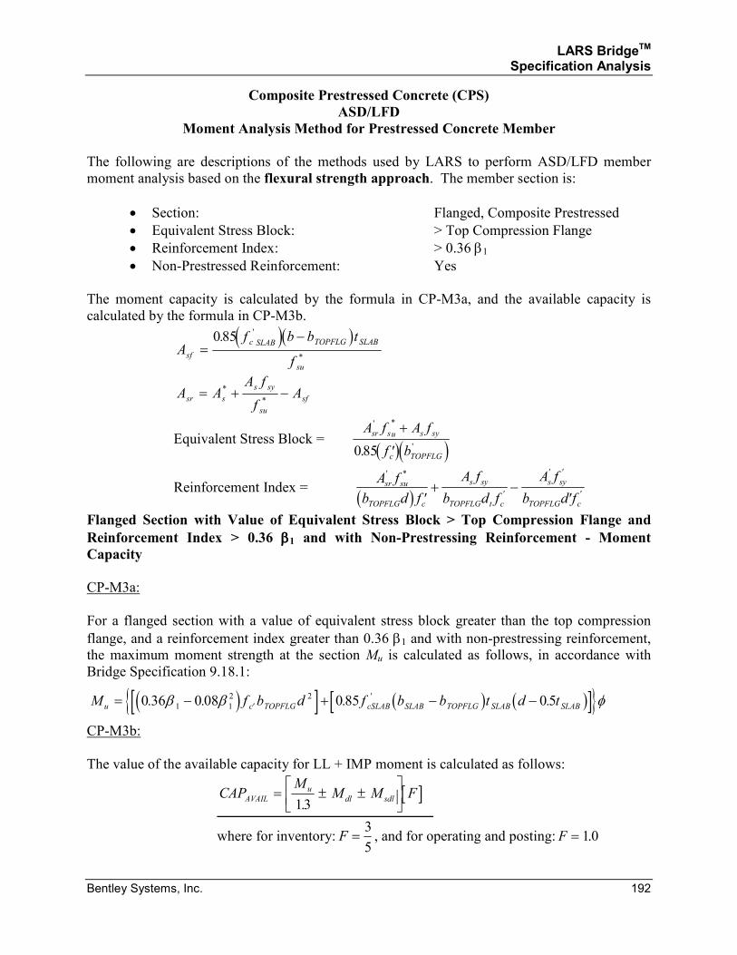
LARS BridgeTM Specification Analysis
Bentley Systems, Inc. 192
Composite Prestressed Concrete (CPS)
ASD/LFD
Moment Analysis Method for Prestressed Concrete Member
The following are descriptions of the methods used by LARS to perform ASD/LFD member
moment analysis based on the flexural strength approach. The member section is:
• Section: Flanged, Composite Prestressed
• Equivalent Stress Block: > Top Compression Flange
• Reinforcement Index: > 0.36 β1
• Non-Prestressed Reinforcement: Yes
The moment capacity is calculated by the formula in CP-M3a, and the available capacity is
calculated by the formula in CP-M3b.
( )( )
Af b b t
fsf
c SLAB TOPFLG SLAB
su
=−085. '
*
A AA f
fAsr s
s sy
su
sf= + −*
*
Equivalent Stress Block = ( )( )
A f A f
f b
sr su s sy
c TOPFLG
' *
'.
+
′085
Reinforcement Index = ( )
A f
b d f
A f
b d f
A f
b d f
sr su
TOPFLG c
s sy
TOPFLG t c
s sy
TOPFLG c
' *
'
' '
'′+ −
′
Flanged Section with Value of Equivalent Stress Block > Top Compression Flange and
Reinforcement Index > 0.36 ββββ1 and with Non-Prestressing Reinforcement - Moment Capacity
CP-M3a:
For a flanged section with a value of equivalent stress block greater than the top compression
flange, and a reinforcement index greater than 0.36 β1 and with non-prestressing reinforcement,
the maximum moment strength at the section Mu is calculated as follows, in accordance with
Bridge Specification 9.18.1:
( )[ ] ( ) ( )[ ]{ }M f b d f b b t d tu c TOPFLG cSLAB SLAB TOPFLG SLAB SLAB= − + − −′0 36 0 08 085 051 1
2 2. . . .'β β φ
CP-M3b:
The value of the available capacity for LL + IMP moment is calculated as follows:
[ ]CAPM
M M FAVAIL
u
dl sdl= ± ±
13.
where for inventory: F =3
5, and for operating and posting: F = 10.
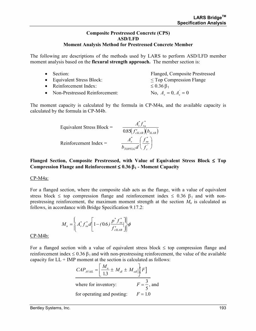
LARS BridgeTM Specification Analysis
Bentley Systems, Inc. 193
Composite Prestressed Concrete (CPS)
ASD/LFD
Moment Analysis Method for Prestressed Concrete Member
The following are descriptions of the methods used by LARS to perform ASD/LFD member
moment analysis based on the flexural strength approach. The member section is:
• Section: Flanged, Composite Prestressed
• Equivalent Stress Block: < Top Compression Flange
• Reinforcement Index: ≤ 0.36 β1
• Non-Prestressed Reinforcement: No, A As s= =0 0, '
The moment capacity is calculated by the formula in CP-M4a, and the available capacity is
calculated by the formula in CP-M4b.
Equivalent Stress Block = ( )( )A f
f b
s su
cSLAB SLAB
* *
.085 ′
Reinforcement Index = A
b d
f
f
s
TOPFLG
su
c
* *
'
Flanged Section, Composite Prestressed, with Value of Equivalent Stress Block ≤≤≤≤ Top Compression Flange and Reinforcement ≤≤≤≤ 0.36 ββββ1 - Moment Capacity
CP-M4a:
For a flanged section, where the composite slab acts as the flange, with a value of equivalent
stress block ≤ top compression flange and reinforcement index ≤ 0.36 β1 and with non-
prestressing reinforcement, the maximum moment strength at the section Mu is calculated as
follows, in accordance with Bridge Specification 9.17.2:
M A f dp f
fu s su
su
cSLAB
= −′
* *
* *
( . )1 06 φ
CP-M4b:
For a flanged section with a value of equivalent stress block ≤ top compression flange and
reinforcement index ≤ 0.36 β1 and with non-prestressing reinforcement, the value of the available
capacity for LL + IMP moment at the section is calculated as follows:
[ ]CAPM
M M FAVAIL
u
dl sdl= ± ±
13.
where for inventory: F =3
5, and
for operating and posting: F = 10.
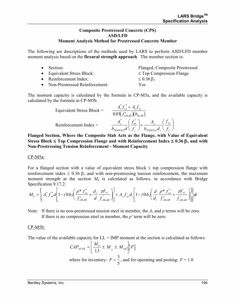
LARS BridgeTM Specification Analysis
Bentley Systems, Inc. 194
Composite Prestressed Concrete (CPS)
ASD/LFD
Moment Analysis Method for Prestressed Concrete Member
The following are descriptions of the methods used by LARS to perform ASD/LFD member
moment analysis based on the flexural strength approach. The member section is:
• Section: Flanged, Composite Prestressed
• Equivalent Stress Block: ≤ Top Compression Flange
• Reinforcement Index: ≤ 0.36 β1
• Non-Prestressed Reinforcement: Yes
The moment capacity is calculated by the formula in CP-M5a, and the available capacity is
calculated by the formula in CP-M5b.
Equivalent Stress Block = ( )( )
A f A f
f b
s su s sy
cSLAB SLAB
* *
.
+
′085
Reinforcement Index = A
b d
f
f
A
b d
f
f
s
TOPFLG
su
c
s
TOPFLG t
sy
c
* *
' '
+
Flanged Section, Where the Composite Slab Acts as the Flange, with Value of Equivalent
Stress Block ≤≤≤≤ Top Compression Flange and with Reinforcement Index ≤≤≤≤ 0.36 ββββ1 and with Non-Prestressing Tension Reinforcement - Moment Capacity
CP-M5a:
For a flanged section with a value of equivalent stress block ≤ top compression flange with
reinforcement index ≤ 0.36 β1 and with non-prestressing tension reinforcement, the maximum
moment strength at the section Mu is calculated as follows, in accordance with Bridge
Specification 9.17.2:
M A f dp f
f
d
d
pf
fA f d
d
d
p f
f
pf
fu s su
su
cSLAB
t sy
cSLAB
s sy t
t
su
cSLAB
sy
cSLAB
= −′
+
+ −
′+
* *
*
'
*
'( . )
*( . )
*1 0 6 1 06 φ
Note: If there is no non-prestressed tension steel in member, the As and p terms will be zero.
If there is no compression steel in member, the p′ term will be zero.
CP-M5b:
The value of the available capacity for LL + IMP moment at the section is calculated as follows:
[ ]CAPM
M M FAVAIL
U
sdldl= ± ±
13.
where for inventory: F =3
5, and for operating and posting: F = 1.0
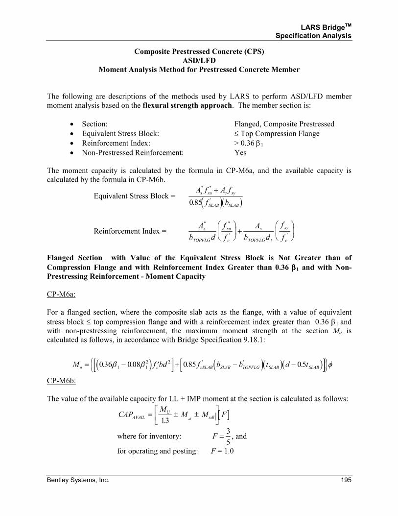
LARS BridgeTM Specification Analysis
Bentley Systems, Inc. 195
Composite Prestressed Concrete (CPS)
ASD/LFD
Moment Analysis Method for Prestressed Concrete Member
The following are descriptions of the methods used by LARS to perform ASD/LFD member
moment analysis based on the flexural strength approach. The member section is:
• Section: Flanged, Composite Prestressed
• Equivalent Stress Block: ≤ Top Compression Flange
• Reinforcement Index: > 0.36 β1
• Non-Prestressed Reinforcement: Yes
The moment capacity is calculated by the formula in CP-M6a, and the available capacity is
calculated by the formula in CP-M6b.
Equivalent Stress Block = ( )( )
A f A f
f b
s su s sy
SLAB SLAB
* *
'.
+
085
Reinforcement Index = A
b d
f
f
A
b d
f
f
s
TOPFLG
su
c
s
TOPFLG t
sy
c
* *
' '
+
Flanged Section with Value of the Equivalent Stress Block is Not Greater than of
Compression Flange and with Reinforcement Index Greater than 0.36 ββββ1 and with Non- Prestressing Reinforcement - Moment Capacity
CP-M6a:
For a flanged section, where the composite slab acts as the flange, with a value of equivalent
stress block ≤ top compression flange and with a reinforcement index greater than 0.36 β1 and
with non-prestressing reinforcement, the maximum moment strength at the section Mu is
calculated as follows, in accordance with Bridge Specification 9.18.1:
( )[ ] ( )( )( )[ ]{ }M f bd f b b t d tu c cSLAB SLAB TOPFLG SLAB SLAB= − ′ + − −036 008 085 051 1
2 2. . . .' 'β β φ
CP-M6b:
The value of the available capacity for LL + IMP moment at the section is calculated as follows:
[ ]CAPM
M M FAVAIL
U
sdldl= ± ±
13.
where for inventory: F =3
5, and
for operating and posting: F = 1.0
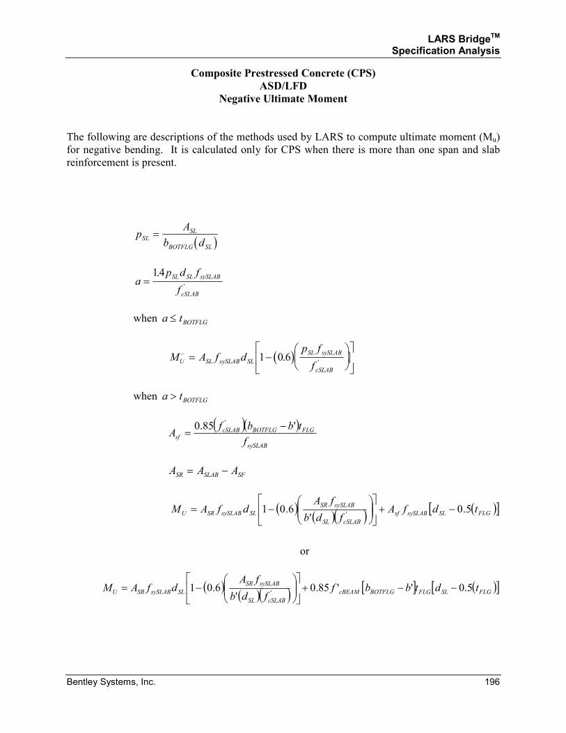
LARS BridgeTM Specification Analysis
Bentley Systems, Inc. 196
Composite Prestressed Concrete (CPS)
ASD/LFD
Negative Ultimate Moment
The following are descriptions of the methods used by LARS to compute ultimate moment (Mu)
for negative bending. It is calculated only for CPS when there is more than one span and slab
reinforcement is present.
( )
pA
b dSL
SL
BOTFLG SL
=
ap d f
f
SL SL sySLAB
cSLAB
=14.
'
when a tBOTFLG≤
( )M A f dp f
fU SL sySLAB SL
SL sySLAB
cSLAB
− = −
1 0 6.
'
when a tBOTFLG>
( )( )
sySLAB
FLGBOTFLGcSLABsf
f
tbbfA
'85.0 ' −=
A A ASR SLAB SF= −
( )
( )( ) ( )[ ]FLGSLsySLABsf
cSLABSL
sySLABSR
SLsySLABSRU tdfAfdb
fAdfAM 5.0
'6.01
'−+
−=
or
( )( )( ) [ ] ( )[ ]FLGSLFLGBOTFLGcBEAM
cSLABSL
sySLABSR
SLsySLABSRU tdtbbffdb
fAdfAM 5.0''85.0
'6.01
'−−+
−=
LARS BridgeTM Specification Analysis
Bentley Systems, Inc. 197
SECTION 3.1.2
PRESTRESSED CONCRETE
AND
COMPOSITE PRESTRESSED CONCRETE
ALLOWABLE STRESS DESIGN AND LOAD FACTOR DESIGN METHOD
LOW TENDON ANALYSIS
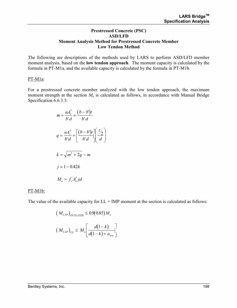
LARS BridgeTM Specification Analysis
Bentley Systems, Inc. 198
Prestressed Concrete (PSC)
ASD/LFD
Moment Analysis Method for Prestressed Concrete Member
Low Tendon Method
The following are descriptions of the methods used by LARS to perform ASD/LFD member
moment analysis, based on the low tendon approach. The moment capacity is calculated by the
formula in PT-M1a, and the available capacity is calculated by the formula in PT-M1b.
PT-M1a:
For a prestressed concrete member analyzed with the low tendon approach, the maximum
moment strength at the section Mu is calculated as follows, in accordance with Manual Bridge
Specification 6.6.3.3:
( )
mnA
b d
b b t
b d
s= +−*
'
'
'
( )
qnA
b d
b b t
b d
t
d
s= +−
*
'
'
'
2
k m q m= + −2 2
j k= −1 0 42.
M f A jdu s s= ' *
PT-M1b:
The value of the available capacity for LL + IMP moment at the section is calculated as follows:
( ) ( )M MCAP OUTLAYER u≤ 09 085. .
( ) ( )( )
M Md k
d k aCAP CL u
low
≤−
− +
1
1
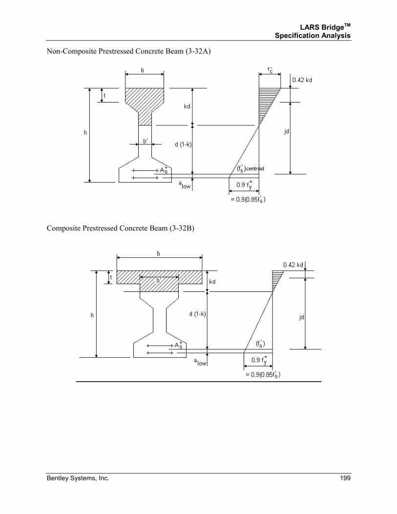
LARS BridgeTM Specification Analysis
Bentley Systems, Inc. 199
Non-Composite Prestressed Concrete Beam (3-32A)
Composite Prestressed Concrete Beam (3-32B)
LARS BridgeTM Specification Analysis
Bentley Systems, Inc. 200
SECTION 3.1.3
PRESTRESSED CONCRETE
AND
COMPOSITE PRESTRESSED CONCRETE
ALLOWABLE STRESS DESIGN AND LOAD FACTOR DESIGN METHODS
SHEAR ANALYSIS
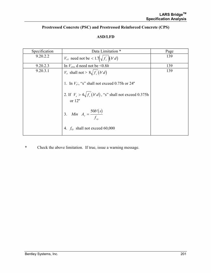
LARS BridgeTM Specification Analysis
Bentley Systems, Inc. 201
Prestressed Concrete (PSC) and Prestressed Reinforced Concrete (CPS)
ASD/LFD
Specification Data Limitation * Page
9.20.2.2 Vci need not be ( )( )< ′17. 'f b dc
139
9.20.2.3 In Vcw, d need not be <0.8h 139
9.20.3.1 Vs shall not > ( )8 f b dc
' ′
1. In Vs:, “s” shall not exceed 0.75h or 24″
2. If ( )V f b ds c> ′4 ' , “s” shall not exceed 0.375h
or 12″
3. ( )
Min Ab s
fv
sy
=′50
4. fsy shall not exceed 60,000
139
* Check the above limitation. If true, issue a warning message.
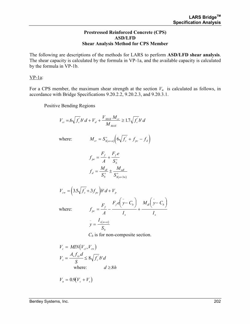
LARS BridgeTM Specification Analysis
Bentley Systems, Inc. 202
Prestressed Reinforced Concrete (CPS)
ASD/LFD
Shear Analysis Method for CPS Member
The following are descriptions of the methods for LARS to perform ASD/LFD shear analysis.
The shear capacity is calculated by the formula in VP-1a, and the available capacity is calculated
by the formula in VP-1b.
VP-1a:
For a CPS member, the maximum shear strength at the section Vu is calculated as follows, in
accordance with Bridge Specifications 9.20.2.2, 9.20.2.3, and 9.20.3.1.
Positive Bending Regions
V f b d VV M
Mf b dci c d
MAX cr
MAX
c= + + ≥. ' . '' '6 17
where: ( ) ( )M S f f fcr b n n c pc d= + −=+ 6 '
fF
A
F e
Spe
f f
b
= + +
( )
fM
S
M
Sd
dl
b
sdl
b n n
= ±+=
+3
( )V f f b d Vcw c pc p= + +35 3. . ''
where: fF
A
F e y C
I
M y C
Ipc
ff b
x
dl b
x
= −−
+
−
− −
( )
yI
S
x n n
b
− ==
Cb is for non-composite section.
( )V MIN V Vc ci cw= ,
VA f d
Sf b ds
v sy
c= ≤ 8 ' '
where: d h≥.8
( )V V Vu c s= +0 9.
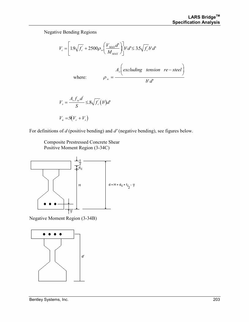
LARS BridgeTM Specification Analysis
Bentley Systems, Inc. 203
Negative Bending Regions
V fV d
Mb d f b dc c w
MAX
MAX
c= +
≤19 2500 35.
'' ' . ' '' 'ρ
where: ρ w
sA excluding tension re steel
b d=
−
' '
( )VA f d
Sf b ds
v sy
c= ≤'
'. ' '8
( )V V Vu c s= +.9
For definitions of d (positive bending) and d′ (negative bending), see figures below.
Composite Prestressed Concrete Shear
Positive Moment Region (3-34C)
Negative Moment Region (3-34B)
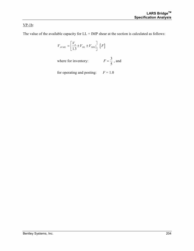
LARS BridgeTM Specification Analysis
Bentley Systems, Inc. 204
VP-1b:
The value of the available capacity for LL + IMP shear at the section is calculated as follows:
[ ]VV
V V FAVAIL
u
DL SDL= ± ±
13.
where for inventory: F =3
5 , and
for operating and posting: F = 1.0
LARS BridgeTM Specification Analysis
Bentley Systems, Inc. 205
SECTION 3.1.4
PRESTRESSED CONCRETE
AND
COMPOSITE PRESTRESSED CONCRETE
ALLOWABLE STRESS DESIGN AND LOAD FACTOR DESIGN METHODS
SERVICEABILITY MOMENT ANALYSIS
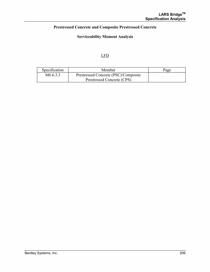
LARS BridgeTM Specification Analysis
Bentley Systems, Inc. 206
Prestressed Concrete and Composite Prestressed Concrete
Serviceability Moment Analysis
LFD
Specification Member Page
M6.6.3.3 Prestressed Concrete (PSC)/Composite
Prestressed Concrete (CPS)
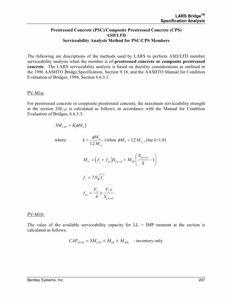
LARS BridgeTM Specification Analysis
Bentley Systems, Inc. 207
Prestressed Concrete (PSC)/Composite Prestressed Concrete (CPS)
ASD/LFD
Serviceability Analysis Method for PSC/CPS Members
The following are descriptions of the methods used by LARS to perform ASD/LFD member
serviceability analysis when the member is of prestressed concrete or composite prestressed
concrete. The LARS serviceability analysis is based on ductility considerations as outlined in
the 1996 AASHTO Bridge Specification, Section 9.18, and the AASHTO Manual for Condition
Evaluation of Bridges, 1994, Section 6.6.3.3.
PV-M1a:
For prestressed concrete or composite prestressed concrete, the maximum serviceability strength
at the section SMCAP is calculated as follows, in accordance with the Manual for Condition
Evaluation of Bridges, 6.6.3.3:
( )SM k MCAP n= φ
where: kM
M
n
cr
=φ12.
(when φM Mn cr< 12. , else k=1.0)
( ) ( )( )
M f f S MS
Scr r pe n n DL
n n= + + −
=
=1
f fr c= 7 5. '
( )
fF
A
F e
Spe
f f
n n
= ±=
PV-M1b:
The value of the available serviceability capacity for LL + IMP moment at the section is
calculated as follows:
CAP SM M MAVAIL CAP DL SDL= ± ± - inventory only
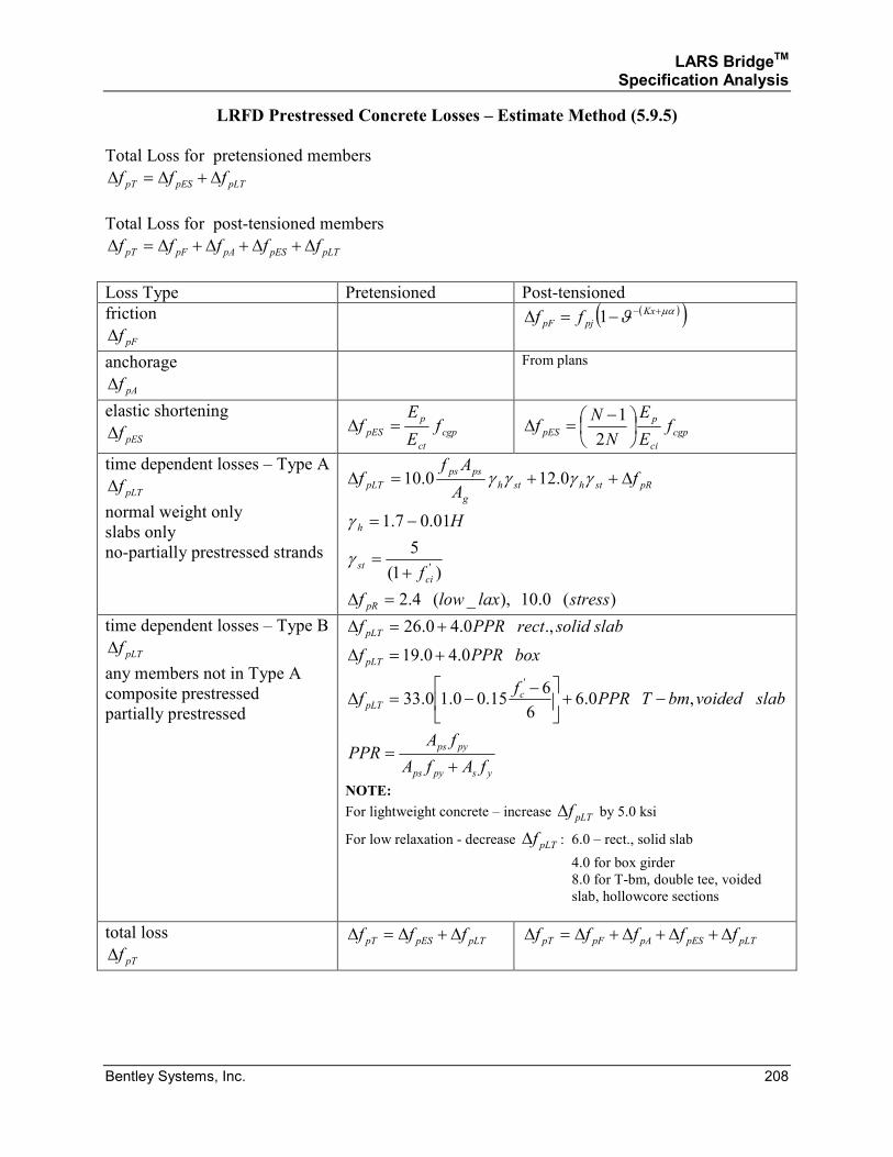
LARS BridgeTM Specification Analysis
Bentley Systems, Inc. 208
LRFD Prestressed Concrete Losses – Estimate Method (5.9.5)
Total Loss for pretensioned members
pLTpESpT fff ∆+∆=∆
Total Loss for post-tensioned members
pLTpESpApFpT fffff ∆+∆+∆+∆=∆
Loss Type Pretensioned Post-tensioned
friction
pFf∆
( )( )µαϑ +−−=∆ Kx
pjpF ff 1
anchorage
pAf∆
From plans
elastic shortening
pESf∆ cgp
ct
p
pES fE
Ef =∆ cgp
ci
p
pES fE
E
N
Nf
−=∆
2
1
time dependent losses – Type A
pLTf∆
normal weight only
slabs only
no-partially prestressed strands
)(0.10),_(4.2
)1(
5
01.07.1
0.120.10
'
stresslaxlowf
f
H
fA
Aff
pR
ci
st
h
pRsthsth
g
psps
pLT
=∆
+=
−=
∆++=∆
γ
γ
γγγγ
time dependent losses – Type B
pLTf∆
any members not in Type A
composite prestressed
partially prestressed
yspyps
pyps
cpLT
pLT
pLT
fAfA
fAPPR
slabvoidedbmTPPRf
f
boxPPRf
slabsolidrectPPRf
+=
−+
−−=∆
+=∆
+=∆
,0.66
615.00.10.33
0.40.19
.,0.40.26
'
NOTE:
For lightweight concrete – increase pLTf∆ by 5.0 ksi
For low relaxation - decrease pLTf∆ : 6.0 – rect., solid slab
4.0 for box girder
8.0 for T-bm, double tee, voided
slab, hollowcore sections
total loss
pTf∆ pLTpESpT fff ∆+∆=∆ pLTpESpApFpT fffff ∆+∆+∆+∆=∆
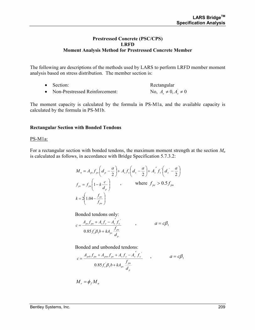
LARS BridgeTM Specification Analysis
Bentley Systems, Inc. 209
Prestressed Concrete (PSC/CPS)
LRFD
Moment Analysis Method for Prestressed Concrete Member
The following are descriptions of the methods used by LARS to perform LRFD member moment
analysis based on stress distribution. The member section is:
• Section: Rectangular
• Non-Prestressed Reinforcement: No, 0,0 ' ≠≠ ss AA
The moment capacity is calculated by the formula in PS-M1a, and the available capacity is
calculated by the formula in PS-M1b.
Rectangular Section with Bonded Tendons
PS-M1a:
For a rectangular section with bonded tendons, the maximum moment strength at the section Mu
is calculated as follows, in accordance with Bridge Specification 5.7.3.2:
−′+
−+
−=222
'' adfA
adfA
adfAM ssssssppspsn
−=
p
pupsd
ckff 1 , where pupe ff 5.0>
−=
pu
py
f
fk 04.12
Bonded tendons only:
p
pu
psc
ysyspups
d
fkAbf
fAfAfAc
+
′−+=
1
'
'
85.0 β
, 1βca =
Bonded and unbonded tendons:
p
pu
psc
ysyspepsupupsb
d
fkAbf
fAfAfAfAc
+
′−++=
1
'
'
85.0 β
, 1βca =
nfr MM φ=
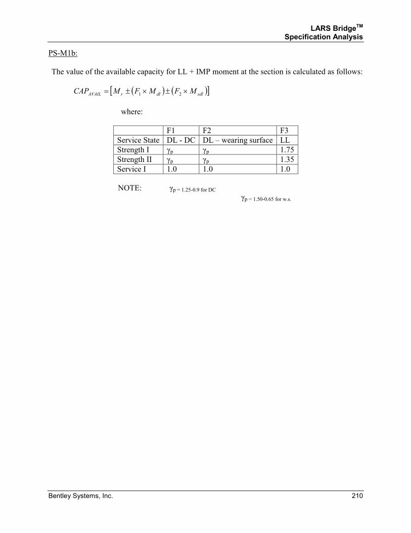
LARS BridgeTM Specification Analysis
Bentley Systems, Inc. 210
PS-M1b:
The value of the available capacity for LL + IMP moment at the section is calculated as follows:
( ) ( )[ ]sdldlrAVAIL MFMFMCAP ×±×±= 21
where:
F1 F2 F3
Service State DL - DC DL – wearing surface LL
Strength I γp γp 1.75
Strength II γp γp 1.35
Service I 1.0 1.0 1.0
NOTE: γp = 1.25-0.9 for DC γp = 1.50-0.65 for w.s.
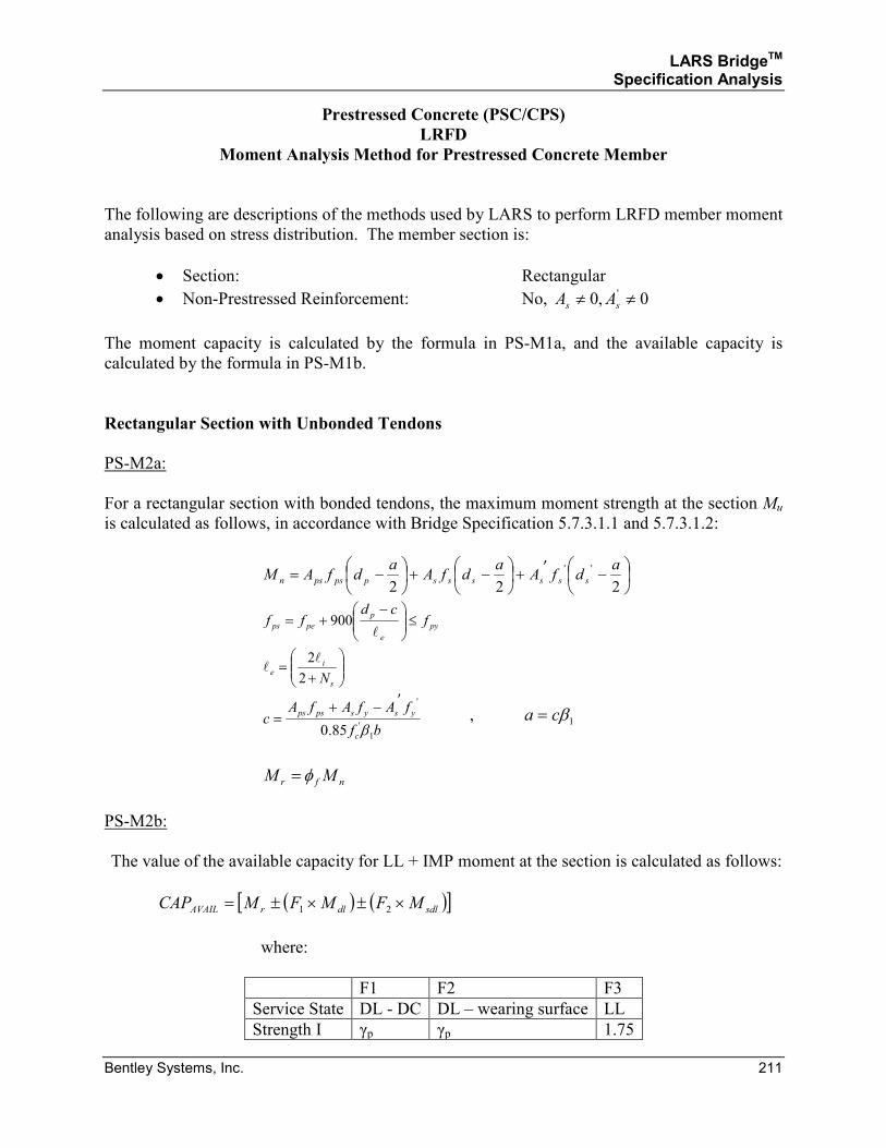
LARS BridgeTM Specification Analysis
Bentley Systems, Inc. 211
Prestressed Concrete (PSC/CPS)
LRFD
Moment Analysis Method for Prestressed Concrete Member
The following are descriptions of the methods used by LARS to perform LRFD member moment
analysis based on stress distribution. The member section is:
• Section: Rectangular
• Non-Prestressed Reinforcement: No, 0,0 ' ≠≠ ss AA
The moment capacity is calculated by the formula in PS-M1a, and the available capacity is
calculated by the formula in PS-M1b.
Rectangular Section with Unbonded Tendons
PS-M2a:
For a rectangular section with bonded tendons, the maximum moment strength at the section Mu
is calculated as follows, in accordance with Bridge Specification 5.7.3.1.1 and 5.7.3.1.2:
−′+
−+
−=222
'' adfA
adfA
adfAM ssssssppspsn
py
e
p
peps fcd
ff ≤
−+=
l900
+=
s
ie
N2
2ll
bf
fAfAfAc
c
ysyspsps
1
'
'
85.0 β
′−+= , 1βca =
nfr MM φ=
PS-M2b:
The value of the available capacity for LL + IMP moment at the section is calculated as follows:
( ) ( )[ ]sdldlrAVAIL MFMFMCAP ×±×±= 21
where:
F1 F2 F3
Service State DL - DC DL – wearing surface LL
Strength I γp γp 1.75
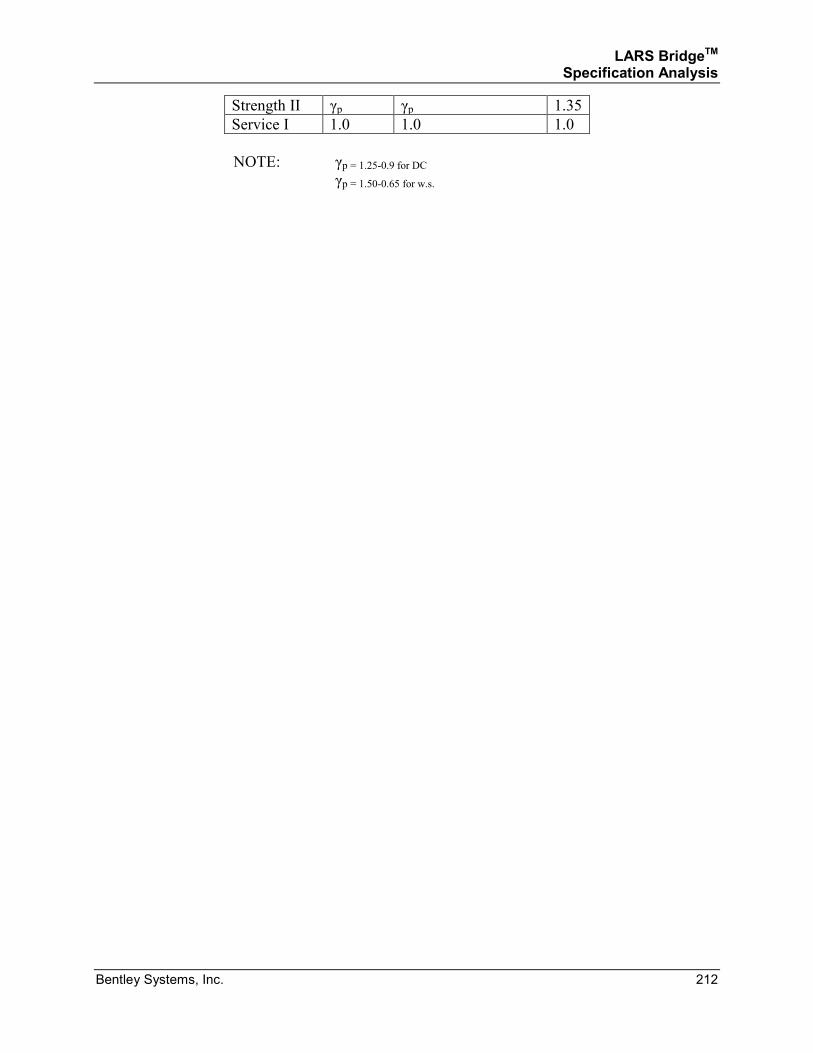
LARS BridgeTM Specification Analysis
Bentley Systems, Inc. 212
Strength II γp γp 1.35
Service I 1.0 1.0 1.0
NOTE: γp = 1.25-0.9 for DC γp = 1.50-0.65 for w.s.
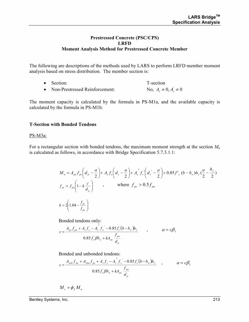
LARS BridgeTM Specification Analysis
Bentley Systems, Inc. 213
Prestressed Concrete (PSC/CPS)
LRFD
Moment Analysis Method for Prestressed Concrete Member
The following are descriptions of the methods used by LARS to perform LRFD member moment
analysis based on stress distribution. The member section is:
• Section: T-section
• Non-Prestressed Reinforcement: No, 0,0 ' ≠≠ ss AA
The moment capacity is calculated by the formula in PS-M1a, and the available capacity is
calculated by the formula in PS-M1b.
T-Section with Bonded Tendons
PS-M3a:
For a rectangular section with bonded tendons, the maximum moment strength at the section Mu
is calculated as follows, in accordance with Bridge Specification 5.7.3.1.1:
)22
()('85.0222
'' f
fwcssssssppspsn
hahbbf
adfA
adfA
adfAM −−+
−′+
−+
−=
−=
p
pupsd
ckff 1 , where pupe ff 5.0>
−=
pu
py
f
fk 04.12
Bonded tendons only:
( )
p
pu
pswc
fwcysyspups
d
fkAbf
hbbffAfAfAc
+
−−′−+=
β'
''
85.0
85.0 , 1βca =
Bonded and unbonded tendons:
( )
p
pu
pswc
fwcysyspepsupupsb
d
fkAbf
hbbffAfAfAfAc
+
−−′−++=
β'
''
85.0
85.0 , 1βca =
nfr MM φ=
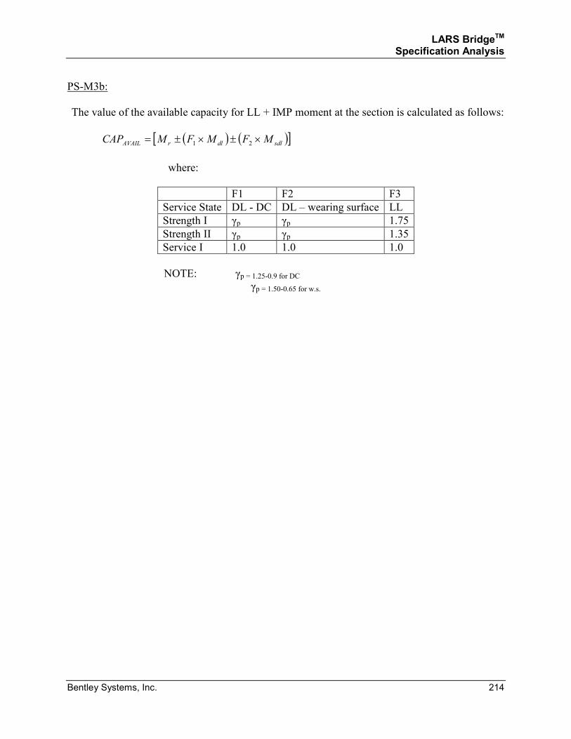
LARS BridgeTM Specification Analysis
Bentley Systems, Inc. 214
PS-M3b:
The value of the available capacity for LL + IMP moment at the section is calculated as follows:
( ) ( )[ ]sdldlrAVAIL MFMFMCAP ×±×±= 21
where:
F1 F2 F3
Service State DL - DC DL – wearing surface LL
Strength I γp γp 1.75
Strength II γp γp 1.35
Service I 1.0 1.0 1.0
NOTE: γp = 1.25-0.9 for DC γp = 1.50-0.65 for w.s.

LARS BridgeTM Specification Analysis
Bentley Systems, Inc. 215
Prestressed Concrete (PSC/CPS)
LRFD
Moment Analysis Method for Prestressed Concrete Member
The following are descriptions of the methods used by LARS to perform LRFD member moment
analysis based on stress distribution. The member section is:
• Section: T-section
• Non-Prestressed Reinforcement: No, 0,0 ' ≠≠ ss AA
The moment capacity is calculated by the formula in PS-M1a, and the available capacity is
calculated by the formula in PS-M1b.
T-Section with Unbonded Tendons
PS-M4a:
For a rectangular section with bonded tendons, the maximum moment strength at the section Mu
is calculated as follows, in accordance with Bridge Specification 5.7.3.1.1 and 5.7.3.1.2:
)22
()('85.0222
1
'' f
fwcssssssppspsn
hahbbf
adfA
adfA
adfAM −−+
−′+
−+
−=
py
e
p
peps fcd
ff ≤
−+=
l900
+=
s
ie
N2
2ll
( )
wc
fwcysyspsps
bf
hbbffAfAfAc
1
'
'
85.0
85.0
β
−−′−+= , 1βca =
nfr MM φ=
PS-M4b:
The value of the available capacity for LL + IMP moment at the section is calculated as follows:
( ) ( )[ ]sdldlrAVAIL MFMFMCAP ×±×±= 21
where:
F1 F2 F3
Service State DL - DC DL – wearing surface LL
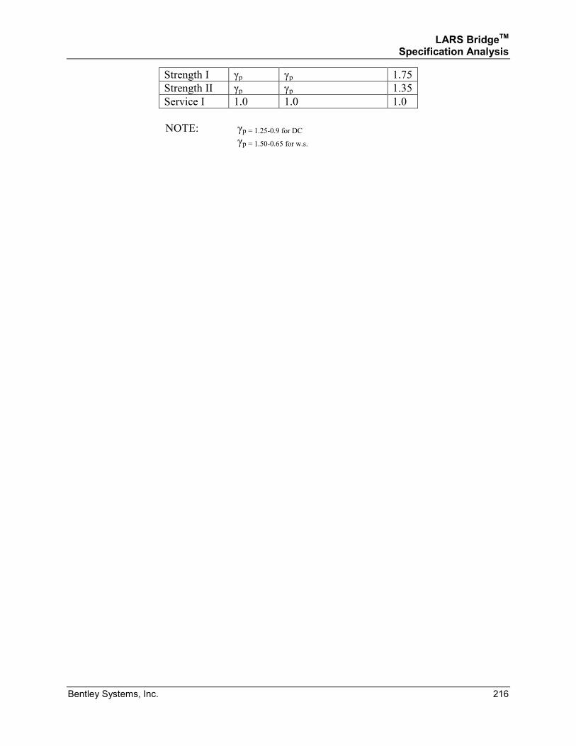
LARS BridgeTM Specification Analysis
Bentley Systems, Inc. 216
Strength I γp γp 1.75
Strength II γp γp 1.35
Service I 1.0 1.0 1.0
NOTE: γp = 1.25-0.9 for DC γp = 1.50-0.65 for w.s.
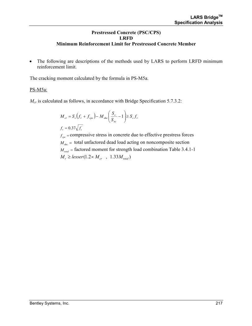
LARS BridgeTM Specification Analysis
Bentley Systems, Inc. 217
Prestressed Concrete (PSC/CPS)
LRFD
Minimum Reinforcement Limit for Prestressed Concrete Member
• The following are descriptions of the methods used by LARS to perform LRFD minimum
reinforcement limit.
The cracking moment calculated by the formula in PS-M5a.
PS-M5a:
Mcr is calculated as follows, in accordance with Bridge Specification 5.7.3.2:
( )rc
nc
c
dnccperccr fSS
SMffSM ≥
−−+= 1
'37.0 cr ff =
=cpef compressive stress in concrete due to effective prestress forces
=dncM total unfactored dead load acting on noncomposite section
=totalM factored moment for strength load combination Table 3.4.1-1
)33.1,2.1( totalcrr MMlesserM ×≥
LARS BridgeTM Specification Analysis
Bentley Systems, Inc. 218
SECTION 3.1.3
PRESTRESSED CONCRETE
AND
COMPOSITE PRESTRESSED CONCRETE
LOAD RESISTANCE FACTOR DESIGN METHODS
SHEAR ANALYSIS
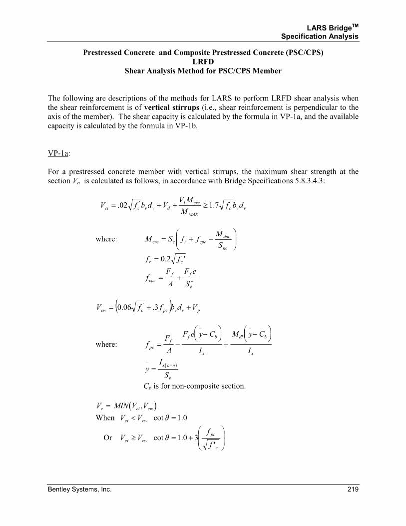
LARS BridgeTM Specification Analysis
Bentley Systems, Inc. 219
Prestressed Concrete and Composite Prestressed Concrete (PSC/CPS)
LRFD
Shear Analysis Method for PSC/CPS Member
The following are descriptions of the methods for LARS to perform LRFD shear analysis when
the shear reinforcement is of vertical stirrups (i.e., shear reinforcement is perpendicular to the
axis of the member). The shear capacity is calculated by the formula in VP-1a, and the available
capacity is calculated by the formula in VP-1b.
VP-1a:
For a prestressed concrete member with vertical stirrups, the maximum shear strength at the
section Vn is calculated as follows, in accordance with Bridge Specifications 5.8.3.4.3:
vvc
MAX
crei
dvvcci dbfM
MVVdbfV '' 7.102. ≥++=
where:
−+=
nc
dnc
cperccreS
MffSM
'2.0 cr ff =
+
+=b
ff
cpeS
eF
A
Ff
( ) pvvpcccw VdbffV ++= 3.06.0 '
where: fF
A
F e y C
I
M y C
Ipc
ff b
x
dl b
x
= −−
+
−
− −
( )
yI
S
x n n
b
− ==
Cb is for non-composite section.
( )V MIN V Vc ci cw= ,
When 0.1cot =< ϑcwci VV
Or
+=≥
c
pc
cwcif
fVV
'30.1cotϑ
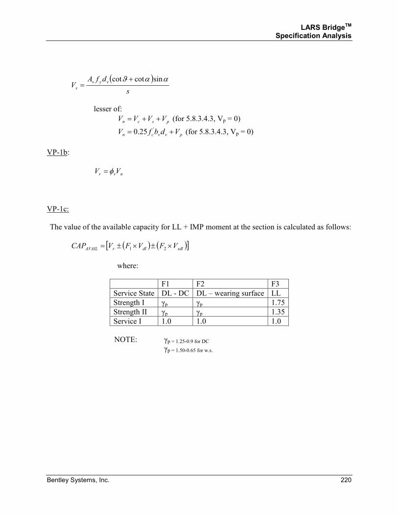
LARS BridgeTM Specification Analysis
Bentley Systems, Inc. 220
( )
s
dfAV
vyv
s
ααϑ sincotcot +=
lesser of:
pscn VVVV ++= (for 5.8.3.4.3, Vp = 0)
pvvcn VdbfV += '25.0 (for 5.8.3.4.3, Vp = 0)
VP-1b:
nvr VV φ=
VP-1c:
The value of the available capacity for LL + IMP moment at the section is calculated as follows:
( ) ( )[ ]sdldlrAVAIL VFVFVCAP ×±×±= 21
where:
F1 F2 F3
Service State DL - DC DL – wearing surface LL
Strength I γp γp 1.75
Strength II γp γp 1.35
Service I 1.0 1.0 1.0
NOTE: γp = 1.25-0.9 for DC γp = 1.50-0.65 for w.s.
LARS BridgeTM Specification Analysis
Bentley Systems, Inc. 221
SECTION 3.1.4
PRESTRESSED CONCRETE
AND
COMPOSITE PRESTRESSED CONCRETE
LOAD RESISTANCE FACTOR DESIGN METHODS
SERVICEABILITY ANALYSIS
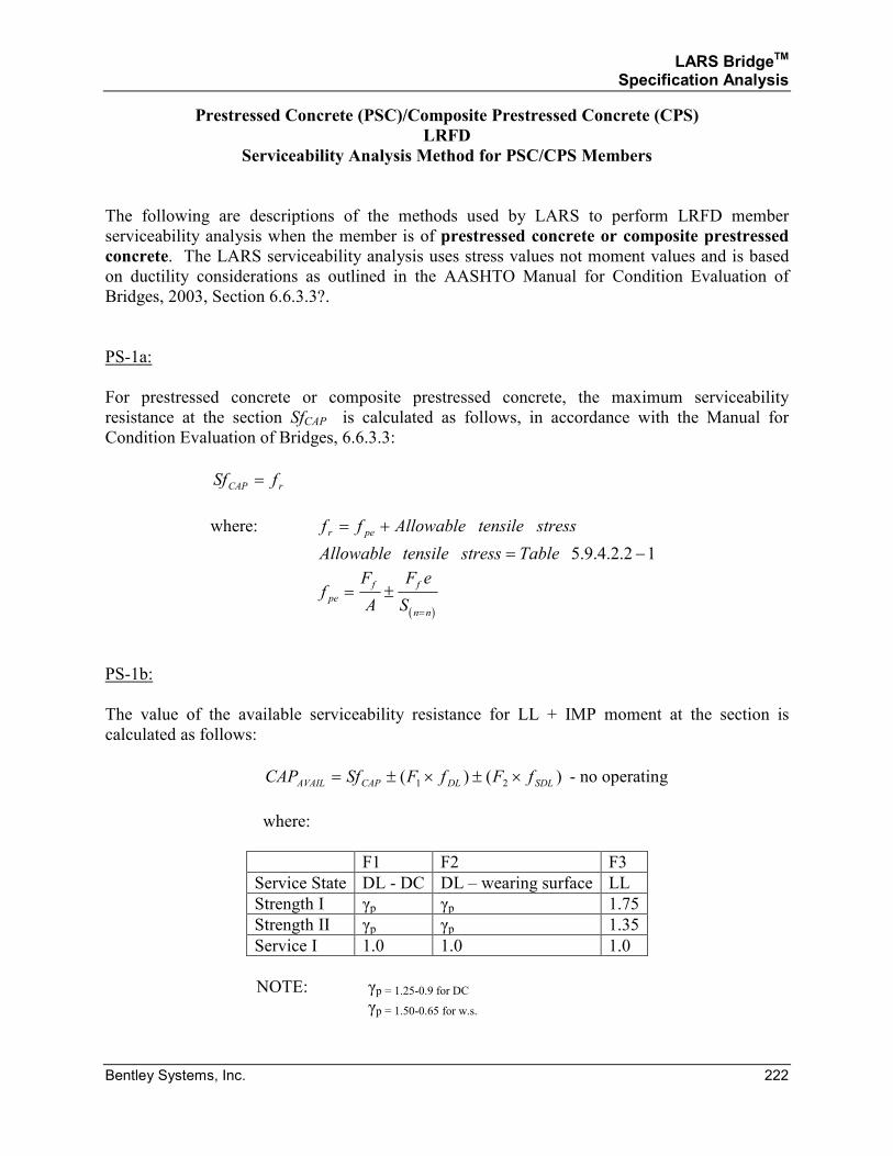
LARS BridgeTM Specification Analysis
Bentley Systems, Inc. 222
Prestressed Concrete (PSC)/Composite Prestressed Concrete (CPS)
LRFD
Serviceability Analysis Method for PSC/CPS Members
The following are descriptions of the methods used by LARS to perform LRFD member
serviceability analysis when the member is of prestressed concrete or composite prestressed
concrete. The LARS serviceability analysis uses stress values not moment values and is based
on ductility considerations as outlined in the AASHTO Manual for Condition Evaluation of
Bridges, 2003, Section 6.6.3.3?.
PS-1a:
For prestressed concrete or composite prestressed concrete, the maximum serviceability
resistance at the section SfCAP is calculated as follows, in accordance with the Manual for
Condition Evaluation of Bridges, 6.6.3.3:
rCAP fSf =
where: stresstensileAllowableff per +=
12.2.4.9.5 −= TablestresstensileAllowable
( )
fF
A
F e
Spe
f f
n n
= ±=
PS-1b:
The value of the available serviceability resistance for LL + IMP moment at the section is
calculated as follows:
)()( 21 SDLDLCAPAVAIL fFfFSfCAP ×±×±= - no operating
where:
F1 F2 F3
Service State DL - DC DL – wearing surface LL
Strength I γp γp 1.75
Strength II γp γp 1.35
Service I 1.0 1.0 1.0
NOTE: γp = 1.25-0.9 for DC γp = 1.50-0.65 for w.s.
LARS BridgeTM Specification Analysis
Bentley Systems, Inc. 223
LARS BridgeTM Specification Analysis
Bentley Systems, Inc. 224
SECTION 4
TIMBER
LARS BridgeTM Specification Analysis
Bentley Systems, Inc. 225
Timber (TMB)4
b = Width of bending member.
d = Depth of bending member.
fb = Allowable bending stress.
fv = Allowable shear stress.
F = Factor of rating type (inventory, operating, posting, etc.).
VAVAIL = Available shear capacity for Live Load + Impact.
VCAP = Shear capacity.
VDL = Dead load shear at the section.
VSDL = Superimposed dead load shear at the section.
4 Selected symbols and references are based on AASHTO Standard Specifications for Highway Bridges, Sixteenth
Edition, while other symbols and references are unique to LARS.
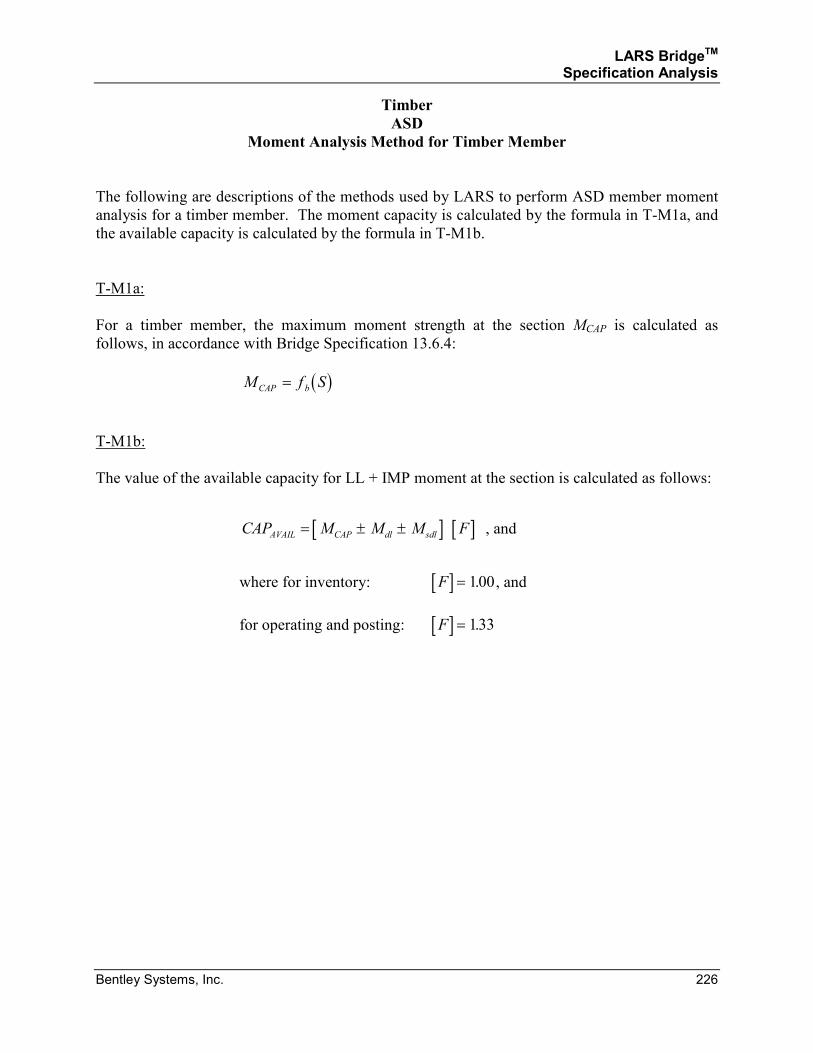
LARS BridgeTM Specification Analysis
Bentley Systems, Inc. 226
Timber
ASD
Moment Analysis Method for Timber Member
The following are descriptions of the methods used by LARS to perform ASD member moment
analysis for a timber member. The moment capacity is calculated by the formula in T-M1a, and
the available capacity is calculated by the formula in T-M1b.
T-M1a:
For a timber member, the maximum moment strength at the section MCAP is calculated as
follows, in accordance with Bridge Specification 13.6.4:
( )M f SCAP b=
T-M1b:
The value of the available capacity for LL + IMP moment at the section is calculated as follows:
[ ] [ ]CAP M M M FAVAIL CAP dl sdl= ± ± , and
where for inventory: [ ]F = 100. , and
for operating and posting: [ ]F = 133.
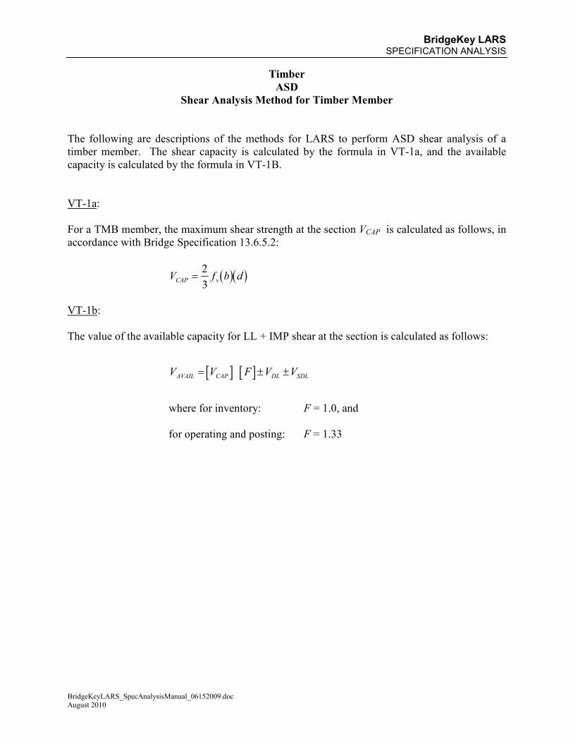
BridgeKey LARS SPECIFICATION ANALYSIS
BridgeKeyLARS_SpecAnalysisManual_06152009.doc August 2010
Timber
ASD
Shear Analysis Method for Timber Member
The following are descriptions of the methods for LARS to perform ASD shear analysis of a
timber member. The shear capacity is calculated by the formula in VT-1a, and the available
capacity is calculated by the formula in VT-1B.
VT-1a:
For a TMB member, the maximum shear strength at the section VCAP is calculated as follows, in
accordance with Bridge Specification 13.6.5.2:
( )( )V f b dCAP v=2
3
VT-1b:
The value of the available capacity for LL + IMP shear at the section is calculated as follows:
[ ] [ ]V V F V VAVAIL CAP DL SDL= ± ±
where for inventory: F = 1.0, and
for operating and posting: F = 1.33
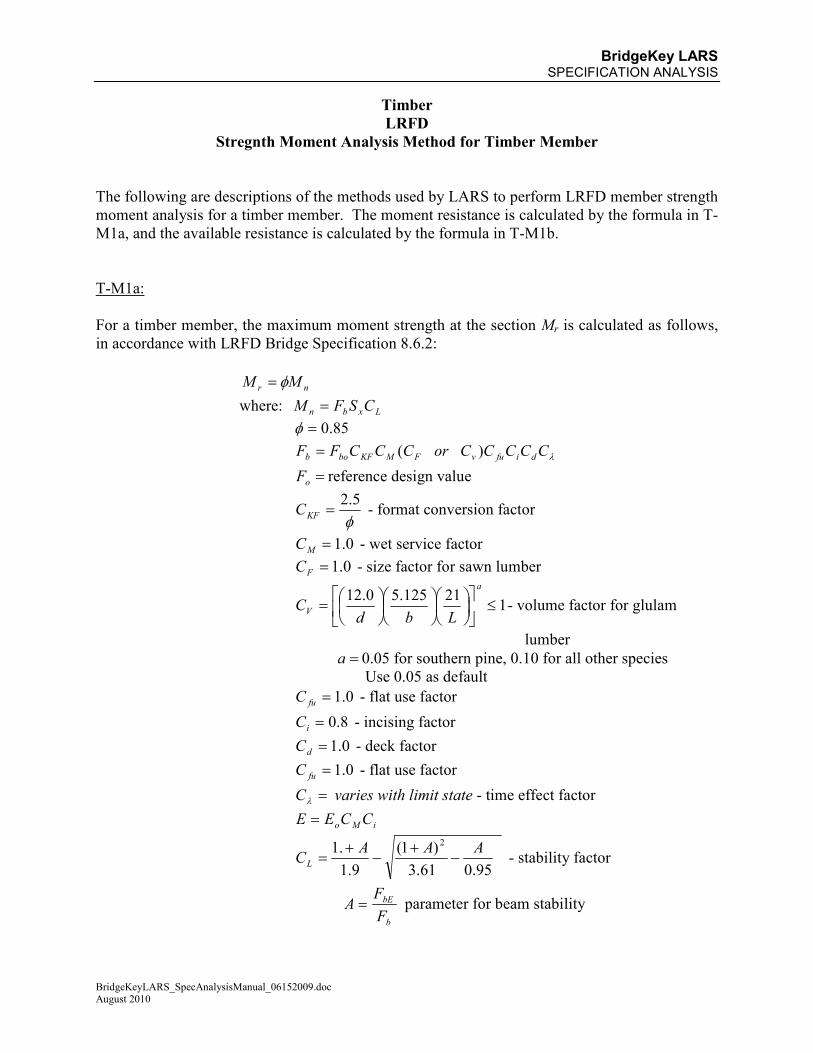
BridgeKey LARS SPECIFICATION ANALYSIS
BridgeKeyLARS_SpecAnalysisManual_06152009.doc August 2010
Timber
LRFD
Stregnth Moment Analysis Method for Timber Member
The following are descriptions of the methods used by LARS to perform LRFD member strength
moment analysis for a timber member. The moment resistance is calculated by the formula in T-
M1a, and the available resistance is calculated by the formula in T-M1b.
T-M1a:
For a timber member, the maximum moment strength at the section Mr is calculated as follows,
in accordance with LRFD Bridge Specification 8.6.2:
nr MM φ=
where: Lxbn CSFM =
85.0=φ
λCCCCCorCCCFF difuvFMKFbob )(=
=oF reference design value
φ5.2
=KFC - format conversion factor
0.1=MC - wet service factor
0.1=FC - size factor for sawn lumber
121125.50.12
≤
=a
VLbd
C - volume factor for glulam
lumber
=a 0.05 for southern pine, 0.10 for all other species
Use 0.05 as default
0.1=fuC - flat use factor
8.0=iC - incising factor
0.1=dC - deck factor
0.1=fuC - flat use factor
=λC varies with limit state - time effect factor
iMo CCEE =
95.061.3
)1(
9.1
.1 2 AAACL −
+−
+= - stability factor
b
bE
F
FA = parameter for beam stability
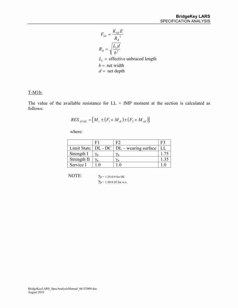
BridgeKey LARS SPECIFICATION ANALYSIS
BridgeKeyLARS_SpecAnalysisManual_06152009.doc August 2010
2
B
bE
bER
EKF =
2b
dLR e
B =
=eL effective unbraced length
=b net width
=d net depth
T-M1b:
The value of the available resistance for LL + IMP moment at the section is calculated as
follows:
( ) ( )[ ]sdldlrAVAIL MFMFMRES ×±×±= 21
where:
F1 F2 F3
Limit State DL - DC DL – wearing surface LL
Strength I γp γp 1.75
Strength II γp γp 1.35
Service I 1.0 1.0 1.0
NOTE: γp = 1.25-0.9 for DC γp = 1.50-0.65 for w.s.
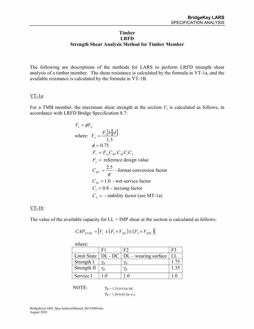
BridgeKey LARS SPECIFICATION ANALYSIS
BridgeKeyLARS_SpecAnalysisManual_06152009.doc August 2010
Timber
LRFD
Strength Shear Analysis Method for Timber Member
The following are descriptions of the methods for LARS to perform LRFD strength shear
analysis of a timber member. The shear resistance is calculated by the formula in VT-1a, and the
available resistance is calculated by the formula in VT-1B.
VT-1a:
For a TMB member, the maximum shear strength at the section Vr is calculated as follows, in
accordance with LRFD Bridge Specification 8.7:
nr VV φ=
where: [ ][ ]5.1
dbFV v
n =
75.0=φ
λCCCCFF iMKFvov =
=oF reference design value
φ5.2
=KFC - format conversion factor
0.1=MC - wet service factor
8.0=iC - incising factor
=LC - stability factor (see MT-1a)
VT-1b:
The value of the available capacity for LL + IMP shear at the section is calculated as follows:
( ) ( )[ ]SDLDLrAVAIL VFVFVCAP ×±×±= 21
where:
F1 F2 F3
Limit State DL - DC DL – wearing surface LL
Strength I γp γp 1.75
Strength II γp γp 1.35
Service I 1.0 1.0 1.0
NOTE: γp = 1.25-0.9 for DC γp = 1.50-0.65 for w.s.