Embed Size (px)
Citation preview
Disk-based StorageOct. 23, 2008
TopicsTopics Storage technologies and trends Locality of reference Caching in the memory hierarchy
lecture-17.ppt
15-213“The course that gives CMU its Zip!”
2 15-213, F’08
Announcements
Exam next ThursdayExam next Thursday style like exam #1: in class, open book/notes, no electronics
3 15-213, F’08
Disk-based storage in computers
Memory/storage hierarchyMemory/storage hierarchy Combining many technologies to balance costs/benefits Recall the memory hierarchy and virtual memory lectures
4 15-213, F’08
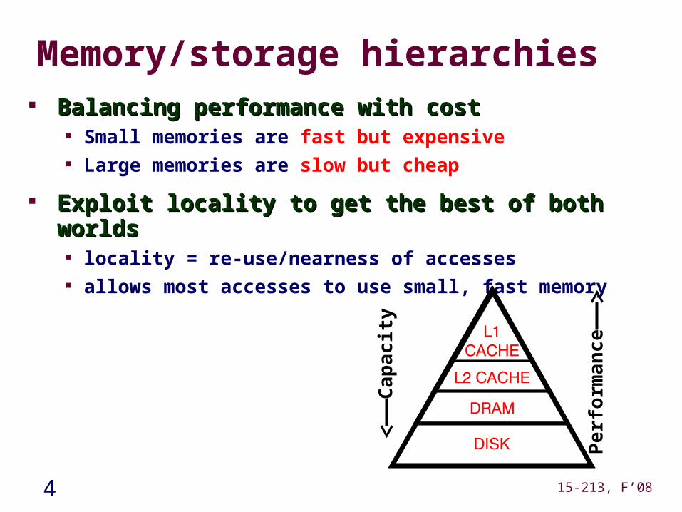
Memory/storage hierarchies Balancing performance with costBalancing performance with cost
Small memories are fast but expensive Large memories are slow but cheap
Exploit locality to get the best of both worldsExploit locality to get the best of both worlds locality = re-use/nearness of accesses allows most accesses to use small, fast memory
Ca
pac
ity
Pe
rfo
rma
nc
e
5 15-213, F’08
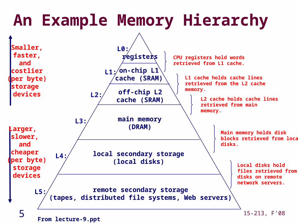
An Example Memory Hierarchy
registers
on-chip L1cache (SRAM)
main memory(DRAM)
local secondary storage(local disks)
Larger, slower,
and cheaper (per byte)storagedevices
remote secondary storage(tapes, distributed file systems, Web servers)
Local disks hold files retrieved from disks on remote network servers.
Main memory holds disk blocks retrieved from local disks.
off-chip L2cache (SRAM)
L1 cache holds cache lines retrieved from the L2 cache memory.
CPU registers hold words retrieved from L1 cache.
L2 cache holds cache lines retrieved from main memory.
L0:
L1:
L2:
L3:
L4:
L5:
Smaller,faster,and
costlier(per byte)storage devices
From lecture-9.ppt
6 15-213, F’08
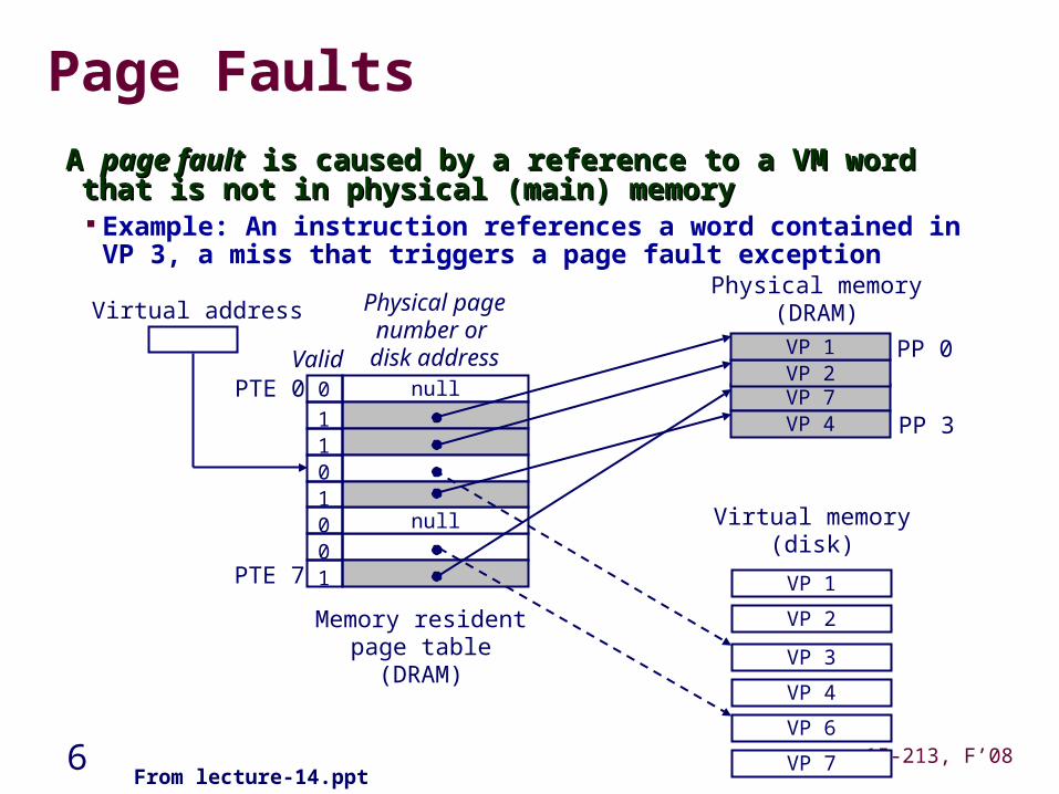
Page Faults
A A page faultpage fault is caused by a reference to a VM word that is not in is caused by a reference to a VM word that is not in physical (main) memoryphysical (main) memory Example: An instruction references a word contained in VP 3, a miss
that triggers a page fault exception
null
null
Memory residentpage table(DRAM)
Physical memory(DRAM)
VP 7VP 4
Virtual memory(disk)
Valid0
1
010
10
1
Physical pagenumber or
disk addressPTE 0
PTE 7
PP 0VP 2VP 1
PP 3
VP 1
VP 2
VP 4
VP 6
VP 7
Virtual address
VP 3
From lecture-14.ppt
7 15-213, F’08
Disk-based storage in computers
Memory/storage hierarchyMemory/storage hierarchy Combining many technologies to balance costs/benefits Recall the memory hierarchy and virtual memory lectures
PersistencePersistence Storing data for lengthy periods of time
DRAM/SRAM is “volatile”: contents lost if power lost Disks are “non-volatile”: contents survive power outages
To be useful, it must also be possible to find it again later this brings in many interesting data organization, consistency,
and management issues take 18-746/15-746 Storage Systems
we’ll talk a bit about file systems next
8 15-213, F’08
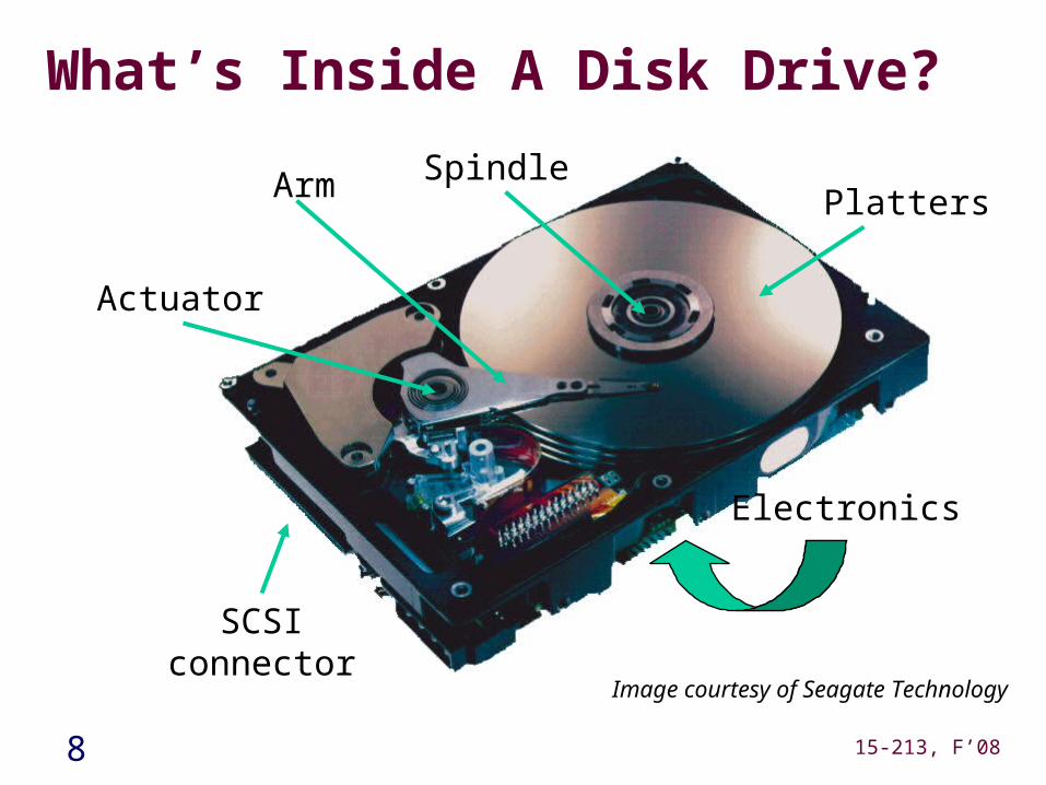
What’s Inside A Disk Drive?
SpindleArm
Actuator
Platters
Electronics
SCSIconnector
Image courtesy of Seagate Technology
9 15-213, F’08
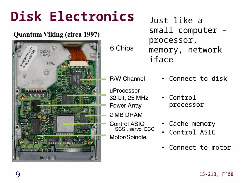
Disk Electronics
• Connect to disk
• Control processor
• Cache memory• Control ASIC
• Connect to motor
Just like a small computer – processor, memory, network iface
10 15-213, F’08
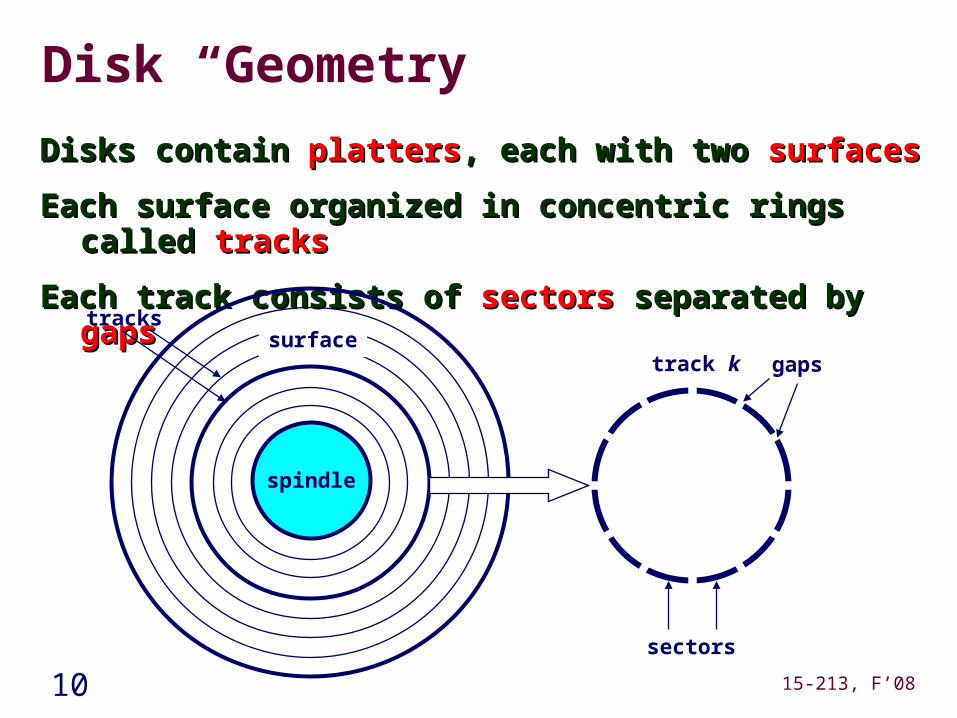
Disk “Geometry”
Disks contain Disks contain plattersplatters, each with two , each with two surfacessurfaces
Each surface organized in concentric rings called Each surface organized in concentric rings called trackstracks
Each track consists of Each track consists of sectorssectors separated by separated by gapsgaps
spindle
surfacetracks
track k
sectors
gaps
11 15-213, F’08
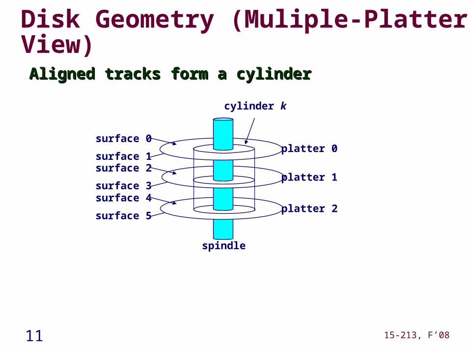
Disk Geometry (Muliple-Platter View)
Aligned tracks form a cylinderAligned tracks form a cylinder
surface 0
surface 1surface 2
surface 3surface 4
surface 5
cylinder k
spindle
platter 0
platter 1
platter 2
12 15-213, F’08
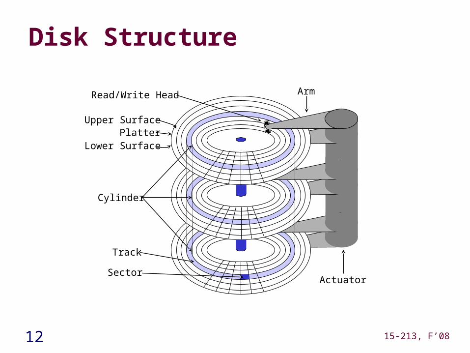
Disk Structure
Read/Write Head
Upper SurfacePlatter
Lower Surface
Cylinder
Track
Sector
Arm
Actuator
13 15-213, F’08
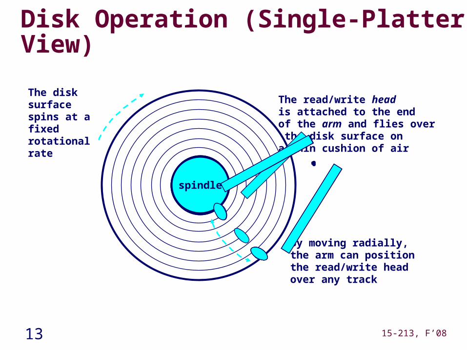
Disk Operation (Single-Platter View)
The disk surface spins at a fixedrotational rate
spindle
By moving radially, the arm can position the read/write head over any track
The read/write headis attached to the endof the arm and flies over the disk surface ona thin cushion of air
spin
dle
spindle
spin
dle
spindle
14 15-213, F’08
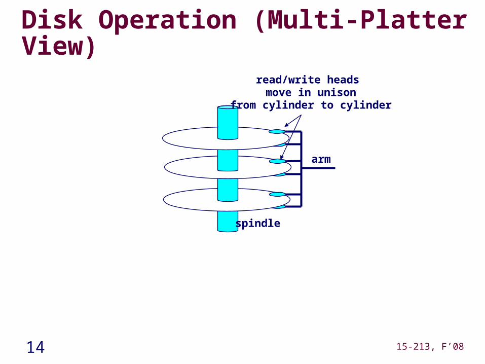
Disk Operation (Multi-Platter View)
arm
read/write heads move in unison
from cylinder to cylinder
spindle
15 15-213, F’08
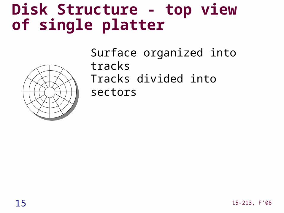
Tracks divided into sectors
Disk Structure - top view of single platter
Surface organized into tracks
16 15-213, F’08
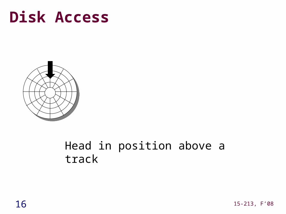
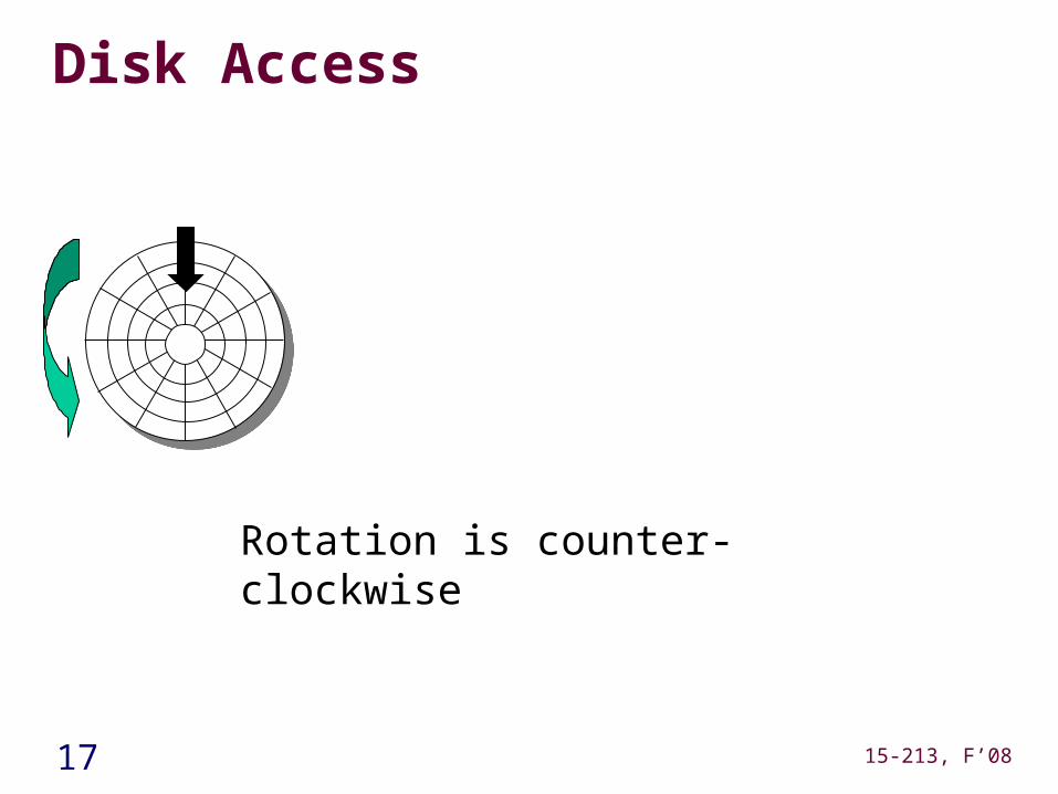
Disk Access
Head in position above a track
17 15-213, F’08
Disk Access
Rotation is counter-clockwise
18 15-213, F’08
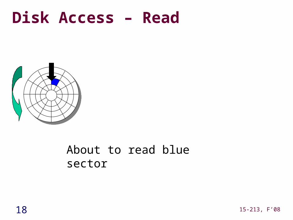
Disk Access – Read
About to read blue sector
19 15-213, F’08
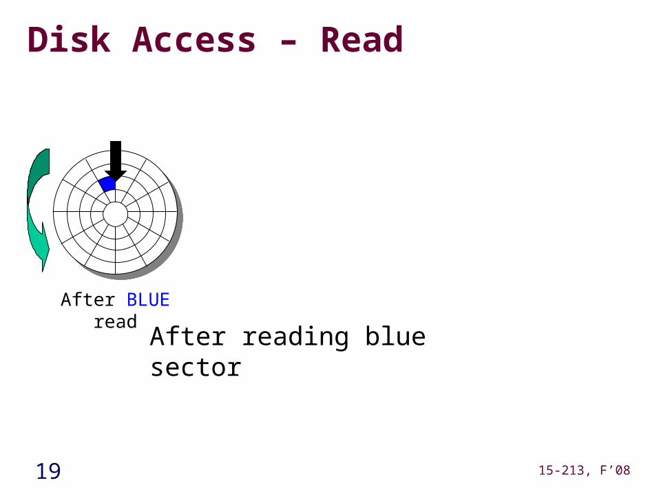
Disk Access – Read
After BLUE read
After reading blue sector
20 15-213, F’08
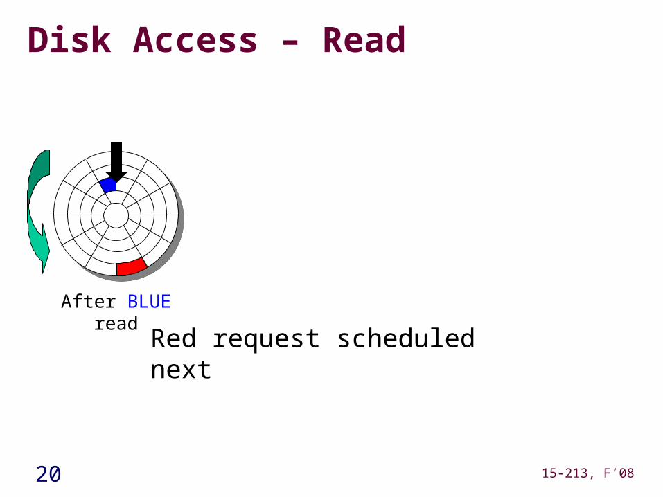
Disk Access – Read
After BLUE read
Red request scheduled next
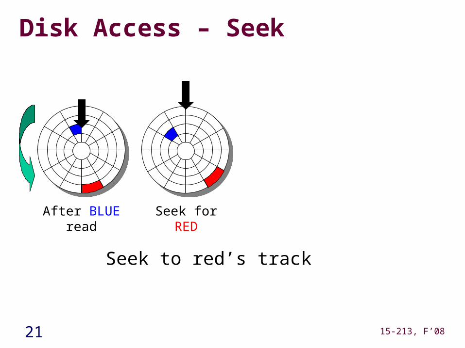
21 15-213, F’08
Disk Access – Seek
After BLUE read Seek for RED
Seek to red’s track
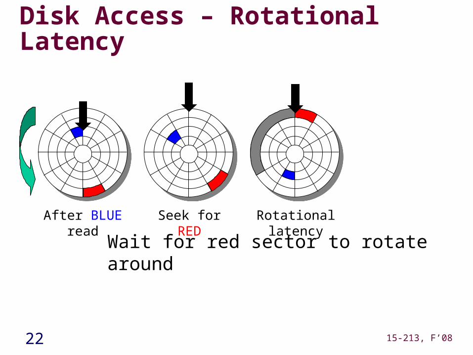
22 15-213, F’08
Disk Access – Rotational Latency
After BLUE read Seek for RED Rotational latency
Wait for red sector to rotate around
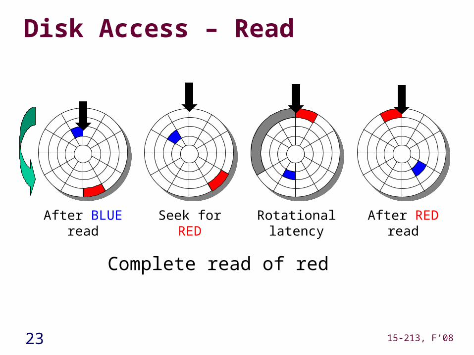
23 15-213, F’08
Disk Access – Read
After BLUE read Seek for RED Rotational latency After RED read
Complete read of red
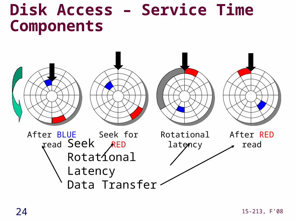
24 15-213, F’08
Disk Access – Service Time Components
After BLUE read Seek for RED Rotational latency After RED read
SeekRotational LatencyData Transfer
25 15-213, F’08
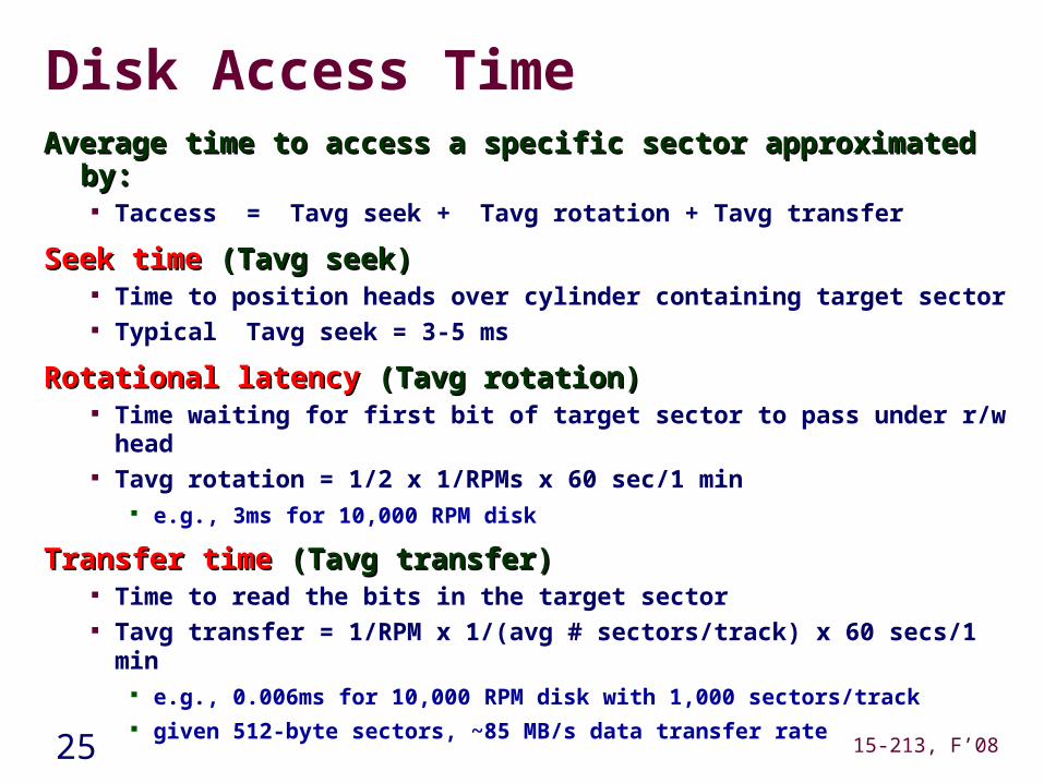
Disk Access TimeAverage time to access a specific sector approximated by:Average time to access a specific sector approximated by:
Taccess = Tavg seek + Tavg rotation + Tavg transfer
Seek timeSeek time (Tavg seek) (Tavg seek) Time to position heads over cylinder containing target sector Typical Tavg seek = 3-5 ms
Rotational latencyRotational latency (Tavg rotation) (Tavg rotation) Time waiting for first bit of target sector to pass under r/w head Tavg rotation = 1/2 x 1/RPMs x 60 sec/1 min
e.g., 3ms for 10,000 RPM disk
Transfer timeTransfer time (Tavg transfer) (Tavg transfer) Time to read the bits in the target sector Tavg transfer = 1/RPM x 1/(avg # sectors/track) x 60 secs/1 min
e.g., 0.006ms for 10,000 RPM disk with 1,000 sectors/track given 512-byte sectors, ~85 MB/s data transfer rate
26 15-213, F’08
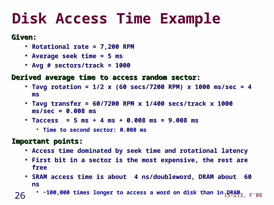
Disk Access Time ExampleGiven:Given:
Rotational rate = 7,200 RPM Average seek time = 5 ms Avg # sectors/track = 1000
Derived average time to access random sector:Derived average time to access random sector: Tavg rotation = 1/2 x (60 secs/7200 RPM) x 1000 ms/sec = 4 ms Tavg transfer = 60/7200 RPM x 1/400 secs/track x 1000 ms/sec =
0.008 ms Taccess = 5 ms + 4 ms + 0.008 ms = 9.008 ms
Time to second sector: 0.008 ms
Important points:Important points: Access time dominated by seek time and rotational latency First bit in a sector is the most expensive, the rest are free SRAM access time is about 4 ns/doubleword, DRAM about 60 ns
~100,000 times longer to access a word on disk than in DRAM
27 15-213, F’08
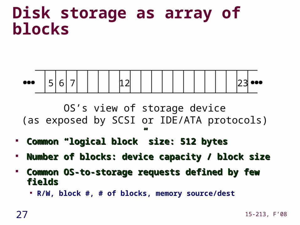
Disk storage as array of blocks
OS’s view of storage device(as exposed by SCSI or IDE/ATA protocols)
Common “logical block” size: 512 bytesCommon “logical block” size: 512 bytes
Number of blocks: device capacity / block sizeNumber of blocks: device capacity / block size
Common OS-to-storage requests defined by few fieldsCommon OS-to-storage requests defined by few fields R/W, block #, # of blocks, memory source/dest
65 7 12 23……
28 15-213, F’08
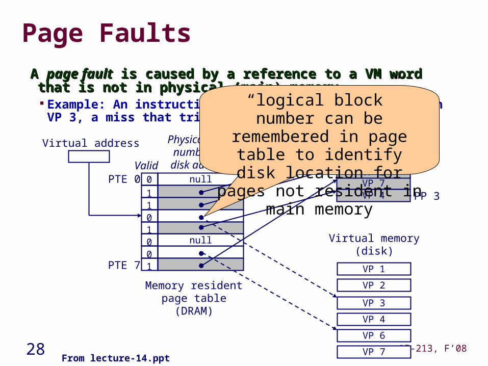
Page Faults
A A page faultpage fault is caused by a reference to a VM word that is not in is caused by a reference to a VM word that is not in physical (main) memoryphysical (main) memory Example: An instruction references a word contained in VP 3, a miss
that triggers a page fault exception
null
null
Memory residentpage table(DRAM)
Physical memory(DRAM)
VP 7VP 4
Virtual memory(disk)
Valid0
1
010
10
1
Physical pagenumber or
disk addressPTE 0
PTE 7
PP 0VP 2VP 1
PP 3
VP 1
VP 2
VP 4
VP 6
VP 7
Virtual address
VP 3
From lecture-14.ppt
“logical block” number can be remembered in page table to
identify disk location for pages not resident in main memory
29 15-213, F’08
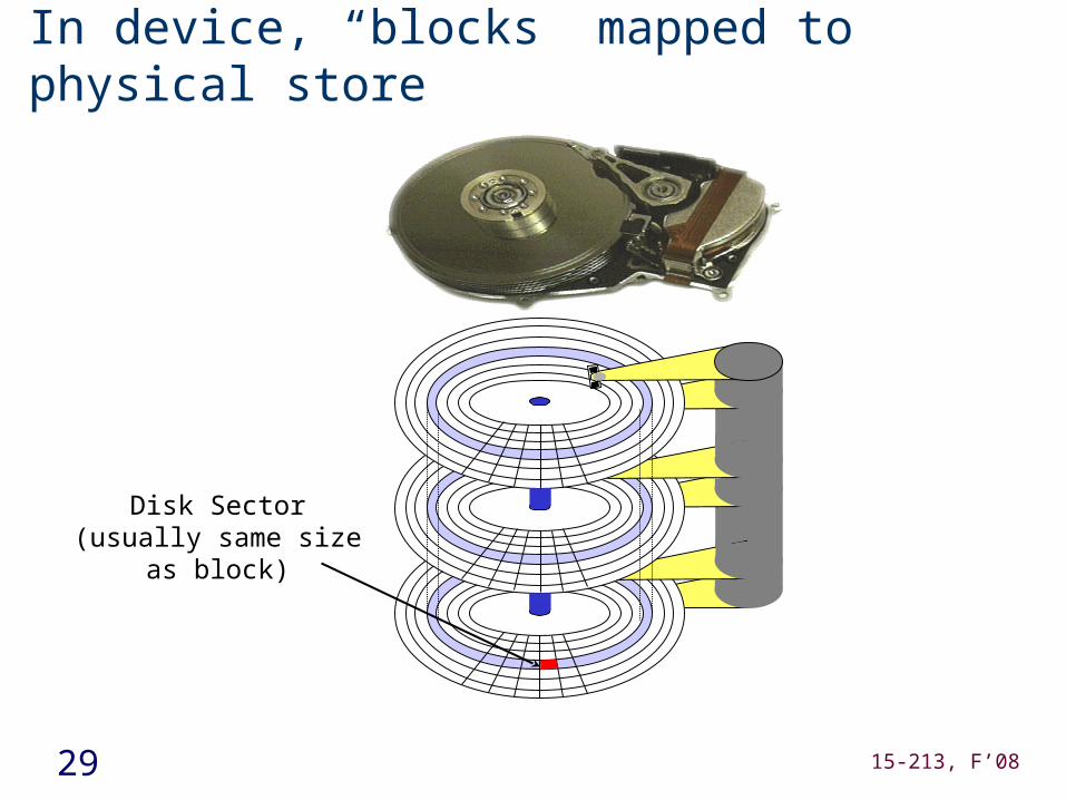
In device, “blocks” mapped to physical store
Disk Sector(usually same size as block)
30 15-213, F’08
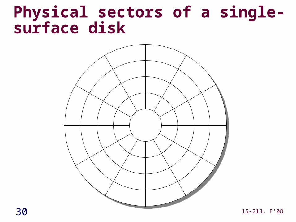
Physical sectors of a single-surface disk
31 15-213, F’08
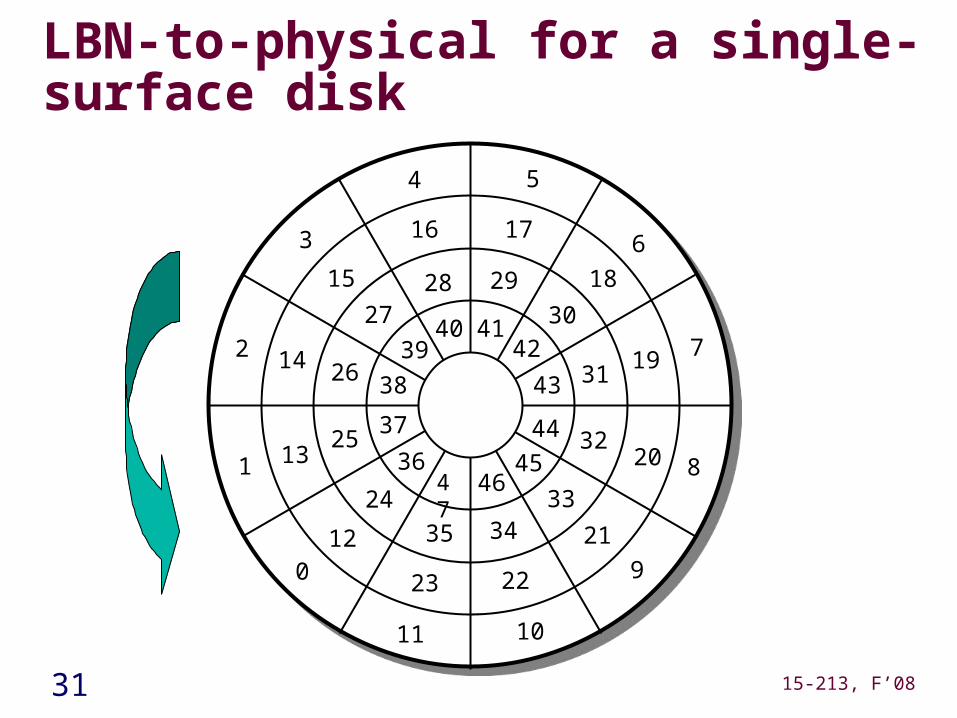
LBN-to-physical for a single-surface disk
10
9
8
7
6
54
3
2
1
012
13
11
22
18
16 17
19
20
21
24
15
14
23
28 2930
31
33
32
34
25
26
27
35
4142
43
44
464536
37
38
4039
47
32 15-213, F’08
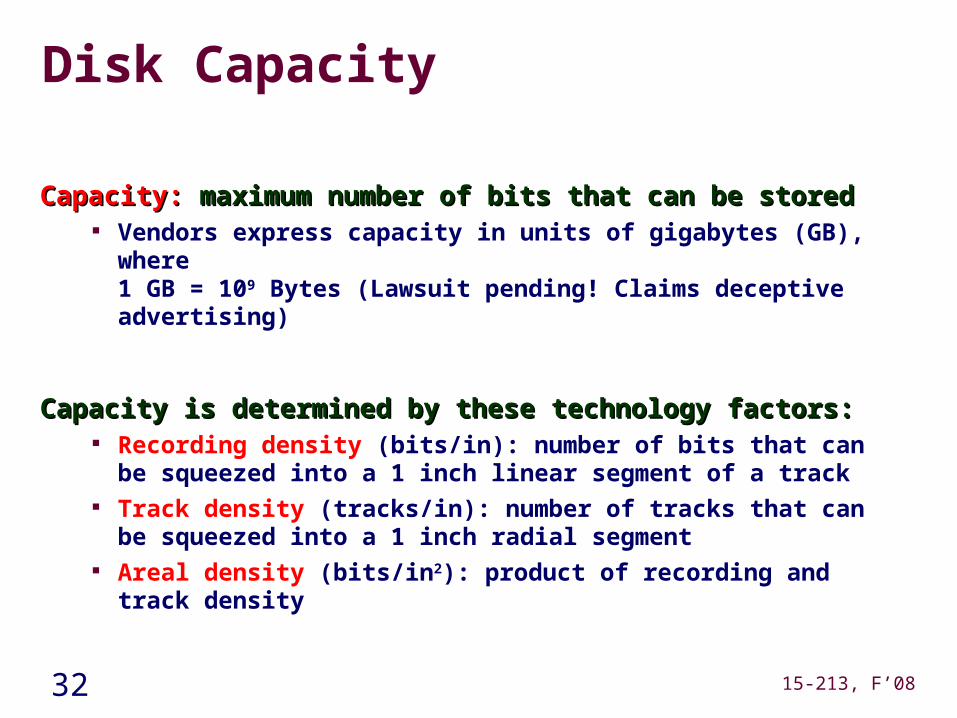
Disk Capacity
Capacity:Capacity: maximum number of bits that can be stored maximum number of bits that can be stored Vendors express capacity in units of gigabytes (GB), where
1 GB = 109 Bytes (Lawsuit pending! Claims deceptive advertising)
Capacity is determined by these technology factors:Capacity is determined by these technology factors: Recording density (bits/in): number of bits that can be squeezed
into a 1 inch linear segment of a track Track density (tracks/in): number of tracks that can be squeezed
into a 1 inch radial segment Areal density (bits/in2): product of recording and track density
33 15-213, F’08
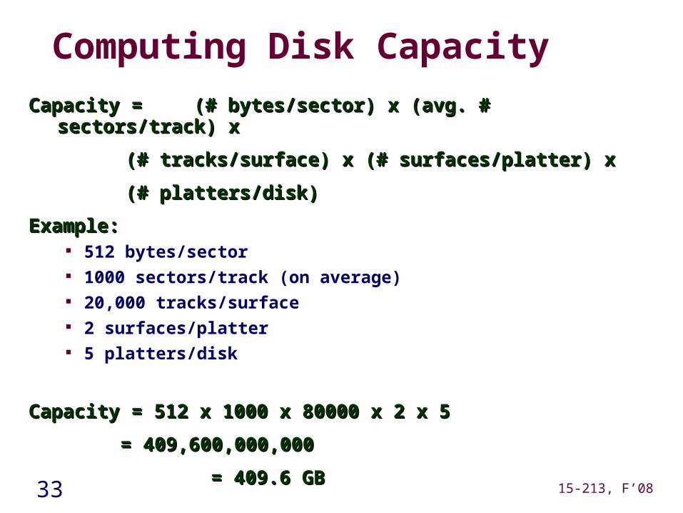
Computing Disk Capacity
Capacity = Capacity = (# bytes/sector) x (avg. # sectors/track) x(# bytes/sector) x (avg. # sectors/track) x
(# tracks/surface) x (# surfaces/platter) x(# tracks/surface) x (# surfaces/platter) x
(# platters/disk)(# platters/disk)
Example:Example: 512 bytes/sector 1000 sectors/track (on average) 20,000 tracks/surface 2 surfaces/platter 5 platters/disk
Capacity = 512 x 1000 x 80000 x 2 x 5Capacity = 512 x 1000 x 80000 x 2 x 5
= 409,600,000,000= 409,600,000,000
= 409.6 GB = 409.6 GB
34 15-213, F’08
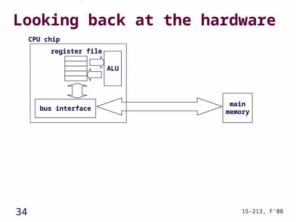
Looking back at the hardware
mainmemorybus interface
ALU
register file
CPU chip
35 15-213, F’08
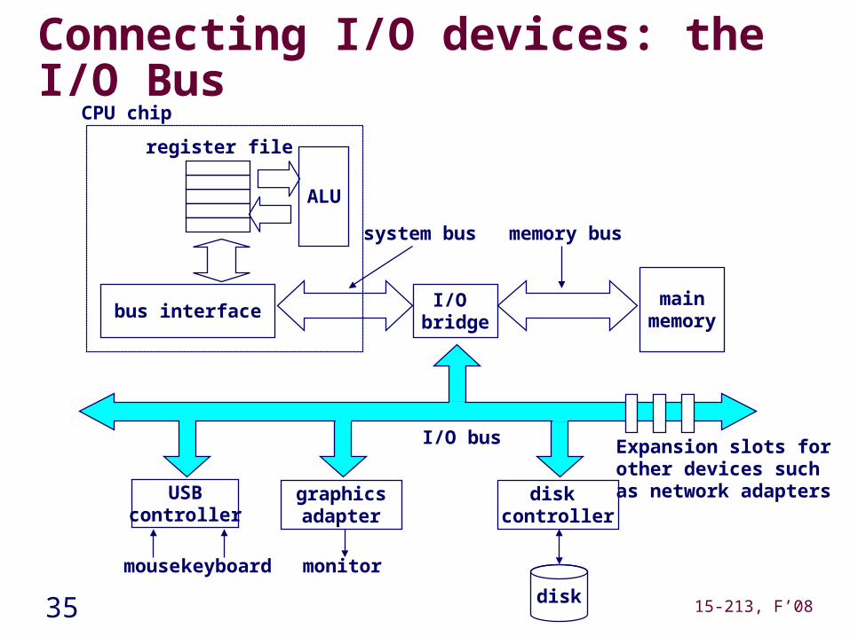
Connecting I/O devices: the I/O Bus
mainmemory
I/O bridge
bus interface
ALU
register file
CPU chip
system bus memory bus
USBcontroller
mousekeyboard
graphicsadapter
monitor
disk controller
disk
I/O bus Expansion slots forother devices suchas network adapters
36 15-213, F’08
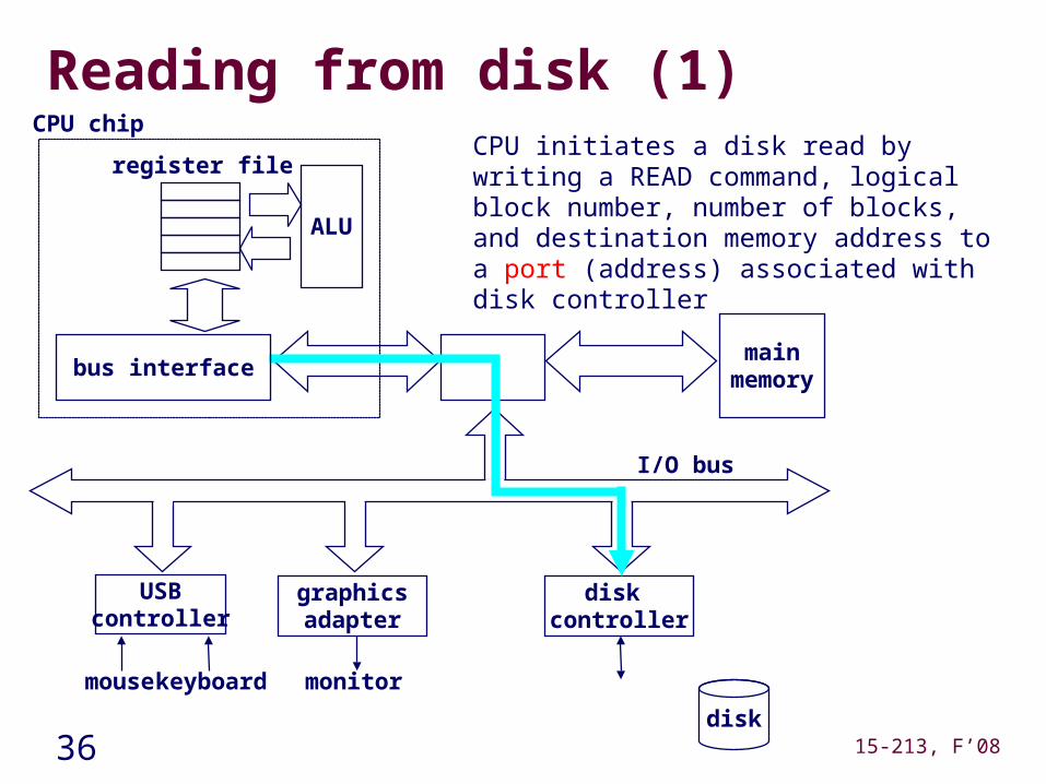
Reading from disk (1)
mainmemory
ALU
register file
CPU chip
disk controller
graphicsadapter
USBcontroller
mousekeyboard monitor
disk
I/O bus
bus interface
CPU initiates a disk read by writing a READ command, logical block number, number of blocks, and destination memory address to a port (address) associated with disk controller
37 15-213, F’08
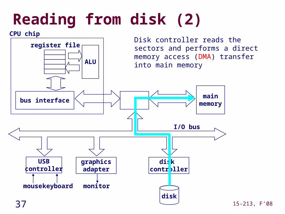
Reading from disk (2)
mainmemory
ALU
register file
CPU chip
disk controller
graphicsadapter
USBcontroller
mousekeyboard monitor
disk
I/O bus
bus interface
Disk controller reads the sectors and performs a direct memory access (DMA) transfer into main memory
38 15-213, F’08
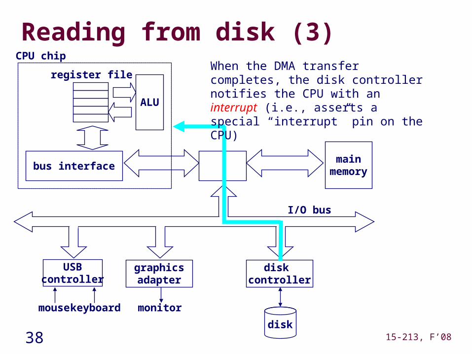
Reading from disk (3)
mainmemory
ALU
register file
CPU chip
disk controller
graphicsadapter
USBcontroller
mousekeyboard monitor
disk
I/O bus
bus interface
When the DMA transfer completes, the disk controller notifies the CPU with an interrupt (i.e., asserts a special “interrupt” pin on the CPU)