Embed Size (px)
Citation preview
Answers for energy.
Discover the World of FACTS TechnologyTechnical Compendium
www.siemens.com/energy/facts
Contents
Chapter Theme Page
1 Facts on FACTS – Theory and Applications 3
1.1 FACTS – What and why? 3
1.2 FACTS for supplying power – Now and in the future 3
1.3 Tasks of FACTS devices 3
2 Basics 4
2.1 Reactive power compensation 4
3 Parallel and Series 5
4 Parallel Compensation 6
4.1 Technology, theory, and basics 6
4.2 Mechanically switched compensation devices 7
4.3 SVC – Static VAR Compensator 8
4.4 SVC PLUS (STATCOM) 16
5 Series Compensation 17
5.1 Technology, theory, and basics 17
5.2 Types 17
5.3 Layout 20
6 Protection and Control 21
6.1 Hardware for control and protection 21
6.2 Human Machine Interface 21
7 Converters for FACTS 22
7.1 LTT – Light Triggered Thyristors 22
8 Complete Solutions 23
2
1.1 FACTS – What and why?FACTS is the acronym for Flexible AC Transmission Systems and refers to a group of resources used to overcome certain limitations in the static and dynamic transmission capacity of electrical networks.
The IEEE defines FACTS as “alternating current trans- mission systems incorporating power-electronics-based and other static controllers to enhance control-lability and power transfer capability.”
The main purpose of these systems is to supply the network as quickly as possible with inductive or capacitive reactive power that is adapted to its partic-ular requirements, while also improving transmission quality and the efficiency of the power transmission system.
1.2 FACTS for supplying power – Now and in the futureThe inevitable globalization and liberalization of energy markets associated with growing deregulation and privatization are increasingly resulting in bottle-necks, uncontrolled load flows, instabilities, and even power transmission failures. Power supplies are increasingly dependent on distributed power plants with higher voltage levels, a greater exchange within meshed systems, and transport to large load centers over what are often long distances. This type of power transmission must be implemented safely and cost-effectively with a view to the future.
Implementing new transmission systems and com-ponents is a long-term strategy for meeting these challenges. Over the short and medium term, modern transmission technologies can be employed at comparatively little expense to rectify or minimize bottlenecks and substantially improve the quality of supply. Often, this makes it possible to postpone investing in new plants and, as a result, to achieve critical advantages over the competition – especially important in de-regulated energy markets in which power supply companies are subject to extreme pricing pressure.
As a world leader in the power transmission and distribution industry, Siemens has developed a number of modern, flexible, high-capacity FACTS for efficiently and reliably regulating voltage, impedance, and phase angle when transmitting power over high-voltage lines.
FACTS provide■■ fast voltage regulation,■■ increased power transfer over long AC lines,■■ damping of active power oscillations, and■■ load flow control in meshed systems,
thereby significantly improving the stability and performance of existing and future transmission systems.
This means that with FACTS, power companies will be able to better utilize their existing transmission networks, substantially increase the availability and reliability of their line networks, and improve both dynamic and transient network stability while ensur-ing a better quality of supply.
1.3 Tasks of FACTS devicesFACTS systems perform the following tasks:■■ Control voltage under various load conditions■■ Balance reactive power (voltage, transmission losses)
■■ Increase the stability of power transmission over long distances
■■ Increase active power stability
1 Facts on FACTS – Theory and Applications
3
∆V
I
V1 V2
X
V2 = V1 – ∆V
V1
∆V
V2V1 V2
∆V
I
(ind.)
I
(cap.)
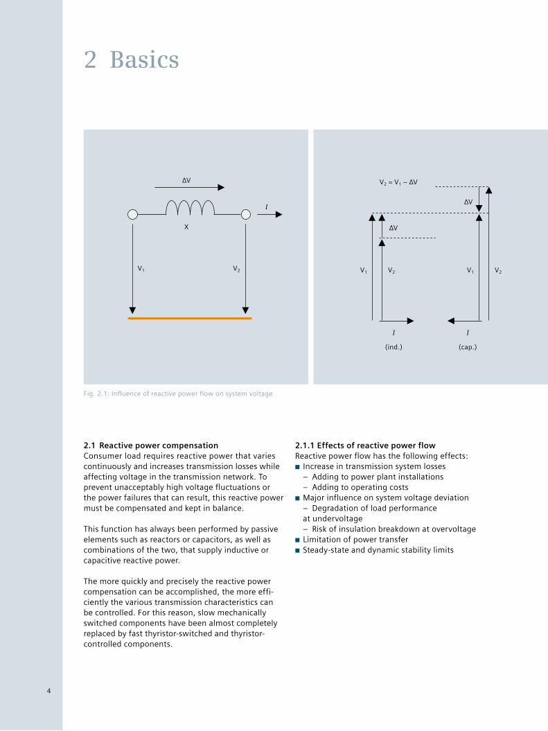
2.1 Reactive power compensationConsumer load requires reactive power that varies continuously and increases transmission losses while affecting voltage in the transmission network. To prevent unacceptably high voltage fluctuations or the power failures that can result, this reactive power must be compensated and kept in balance.
This function has always been performed by passive elements such as reactors or capacitors, as well as combinations of the two, that supply inductive or capacitive reactive power.
The more quickly and precisely the reactive power compensation can be accomplished, the more effi-ciently the various transmission characteristics can be controlled. For this reason, slow mechanically switched components have been almost completely replaced by fast thyristor-switched and thyristor- controlled components.
2.1.1 Effects of reactive power flow Reactive power flow has the following effects:■■ Increase in transmission system losses – Adding to power plant installations – Adding to operating costs
■■ Major influence on system voltage deviation – Degradation of load performance at undervoltage – Risk of insulation breakdown at overvoltage
■■ Limitation of power transfer■■ Steady-state and dynamic stability limits
2 Basics
Fig. 2.1: Influence of reactive power flow on system voltage
4
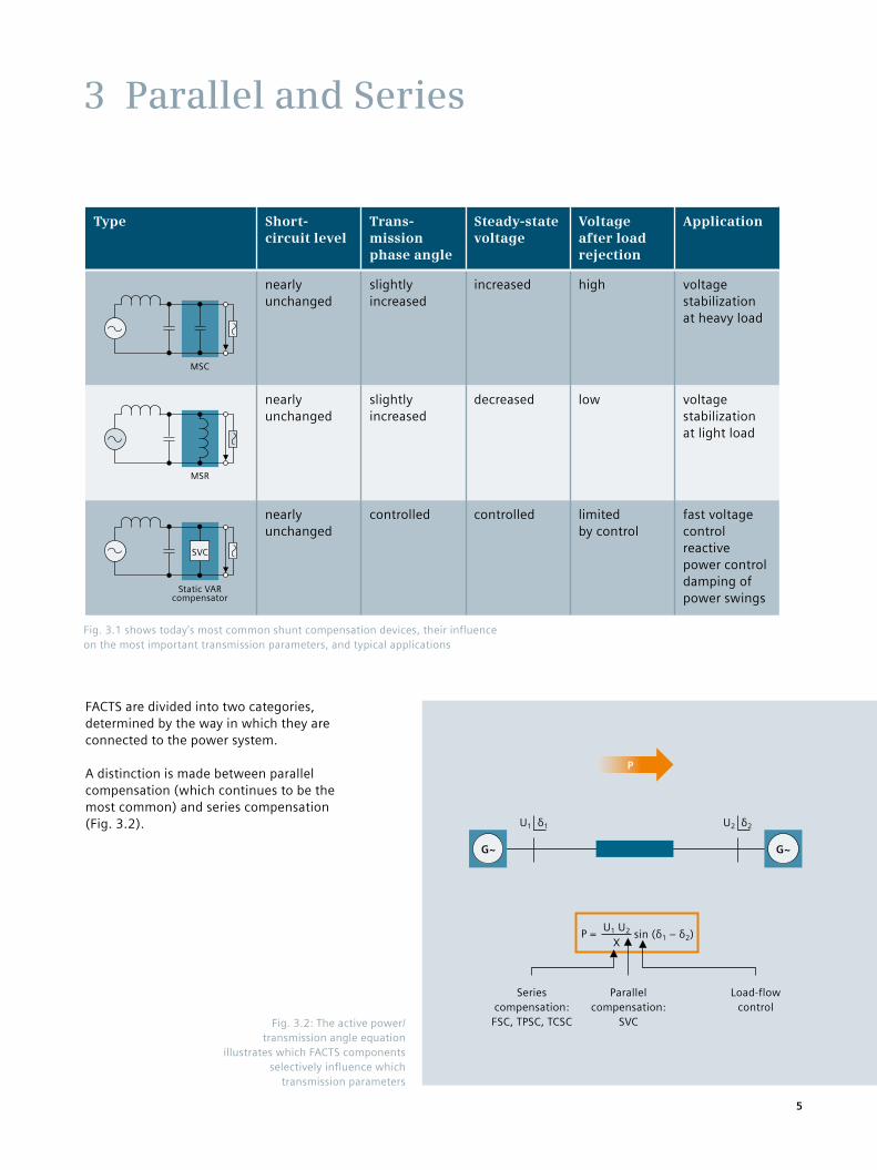
FACTS are divided into two categories, determined by the way in which they are connected to the power system.
A distinction is made between parallel compensation (which continues to be the most common) and series compensation (Fig. 3.2).
3 Parallel and Series
Type Short- circuit level
Trans- mission phase angle
Steady-state voltage
Voltage after load rejection
Application
MSC
nearly unchanged
slightly increased
increased high voltage stabilization at heavy load
MSR
nearly unchanged
slightly increased
decreased low voltage stabilization at light load
Static VAR compensator
SVC
nearly unchanged
controlled controlled limited by control
fast voltage control reactive power control damping of power swings
Fig. 3.1 shows today’s most common shunt compensation devices, their influence on the most important transmission parameters, and typical applications
P
G~ G~
U1 δ1 U2 δ2
Series compensation:
FSC, TPSC, TCSC
Parallel compensation:
SVC
Load-flow control
P = U1 U2
Xsin (δ1 – δ2)
Fig. 3.2: The active power/ transmission angle equation
illustrates which FACTS components selectively influence which
transmission parameters
5
4.1 Technology, theory, and basicsParallel (between a bus bar and ground) reactive power compensation can be used to selectively influence important transmission parameters. Parallel capacitor banks support the voltage under heavy load conditions. This protection can increase maximum transmittable power, regulate the voltage profile, and prevent voltage instability. Parallel reac-tors prevent overvoltages under low load conditions. The key components of a parallel reactive power compensation system are thyristor-switched capaci-tors (TSCs) and thyristor-controlled reactors (TCRs), which can be supplemented with filter branches as needed.
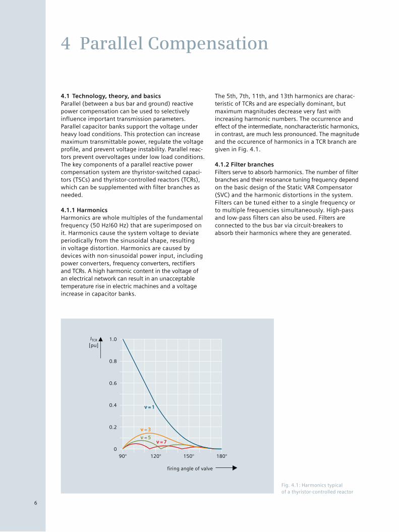
4.1.1 HarmonicsHarmonics are whole multiples of the fundamental frequency (50 Hz/60 Hz) that are superimposed on it. Harmonics cause the system voltage to deviate periodically from the sinusoidal shape, resulting in voltage distortion. Harmonics are caused by devices with non-sinusoidal power input, including power converters, frequency converters, rectifiers and TCRs. A high harmonic content in the voltage of an electrical network can result in an unacceptable temperature rise in electric machines and a voltage increase in capacitor banks.
The 5th, 7th, 11th, and 13th harmonics are charac-teristic of TCRs and are especially dominant, but maximum magnitudes decrease very fast with increasing harmonic numbers. The occurrence and effect of the intermediate, noncharacteristic harmonics, in contrast, are much less pronounced. The magnitude and the occurence of harmonics in a TCR branch are given in Fig. 4.1.
4.1.2 Filter branchesFilters serve to absorb harmonics. The number of filter branches and their resonance tuning frequency depend on the basic design of the Static VAR Compensator (SVC) and the harmonic distortions in the system. Filters can be tuned either to a single frequency or to multiple frequencies simultaneously. High-pass and low-pass filters can also be used. Filters are connected to the bus bar via circuit-breakers to absorb their harmonics where they are generated.
4 Parallel Compensation
Fig. 4.1: Harmonics typical of a thyristor-controlled reactor
firing angle of valve
0
0.2
0.4
0.6
0.8
1.0
90° 120° 150° 180°
ITCR [pu]
ν = 1
ν = 3
ν = 5ν = 7
6
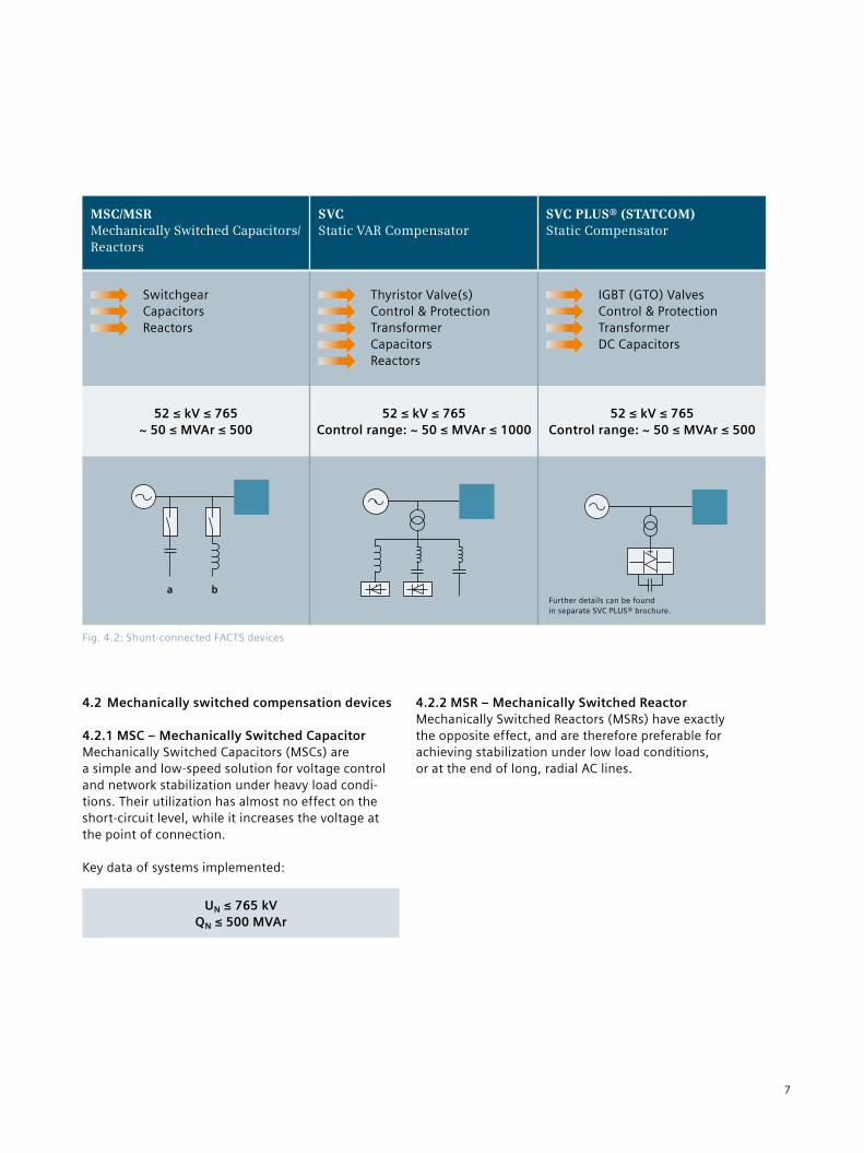
4.2 Mechanically switched compensation devices
4.2.1 MSC – Mechanically Switched CapacitorMechanically Switched Capacitors (MSCs) are a simple and low-speed solution for voltage control and network stabilization under heavy load condi-tions. Their utilization has almost no effect on the short-circuit level, while it increases the voltage at the point of connection.
Key data of systems implemented:
UN ≤ 765 kVQN ≤ 500 MVAr
4.2.2 MSR – Mechanically Switched ReactorMechanically Switched Reactors (MSRs) have exactly the opposite effect, and are therefore preferable for achieving stabilization under low load conditions, or at the end of long, radial AC lines.
Fig. 4.2: Shunt-connected FACTS devices
MSC/MSR Mechanically Switched Capacitors/Reactors
SVC Static VAR Compensator
SVC PLUS® (STATCOM) Static Compensator
Switchgear Capacitors Reactors
Thyristor Valve(s) Control & Protection Transformer Capacitors Reactors
IGBT (GTO) Valves Control & Protection Transformer DC Capacitors
52 ≤ kV ≤ 765~ 50 ≤ MVAr ≤ 500
52 ≤ kV ≤ 765Control range: ~ 50 ≤ MVAr ≤ 1000
52 ≤ kV ≤ 765Control range: ~ 50 ≤ MVAr ≤ 500
a bFurther details can be found in separate SVC PLUS® brochure.
7
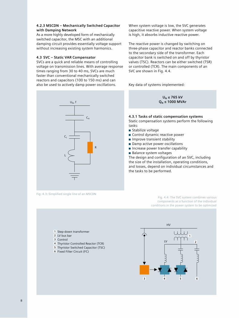
4.2.3 MSCDN – Mechanically Switched Capacitor with Damping NetworkAs a more highly developed form of mechanically switched capacitor, the MSC with an additional damping circuit provides essentially voltage support without increasing existing system harmonics.
4.3 SVC – Static VAR CompensatorSVCs are a quick and reliable means of controlling voltage on transmission lines. With average response times ranging from 30 to 40 ms, SVCs are much faster than conventional mechanically switched reactors and capacitors (100 to 150 ms) and can also be used to actively damp power oscillations.
When system voltage is low, the SVC generates capacitive reactive power. When system voltage is high, it absorbs inductive reactive power.
The reactive power is changed by switching on three-phase capacitor and reactor banks connected to the secondary side of the transformer. Each capacitor bank is switched on and off by thyristor valves (TSC). Reactors can be either switched (TSR) or controlled (TCR). The main components of an SVC are shown in Fig. 4.4.
Key data of systems implemented:
UN ≤ 765 kVQN ≤ 1000 MVAr
4.3.1 Tasks of static compensation systemsStatic compensation systems perform the following tasks:■■ Stabilize voltage■■ Control dynamic reactive power■■ Improve transient stability■■ Damp active power oscillations■■ Increase power transfer capability■■ Balance system voltages
The design and configuration of an SVC, including the size of the installation, operating conditions, and losses, depend on individual circumstances and the tasks to be performed.
Fig. 4.3: Simplified single line of an MSCDN
UN, f
CL
L
CH
R
Fig. 4.4: The SVC system combines various components as a function of the individual
conditions in the power system to be optimized
1 Step-down transformer 2 LV bus bar 3 Control 4 Thyristor Controlled Reactor (TCR) 5 Thyristor Switched Capacitor (TSC) 6 Fixed Filter Circuit (FC)
HV
LV
1
2
3 4 5 6
8
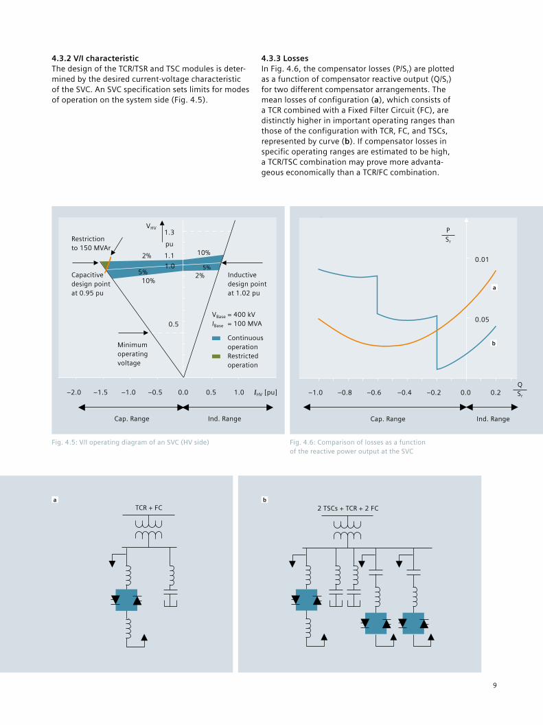
4.3.2 V/I characteristicThe design of the TCR/TSR and TSC modules is deter-mined by the desired current-voltage characteristic of the SVC. An SVC specification sets limits for modes of operation on the system side (Fig. 4.5).
Fig. 4.5: V/I operating diagram of an SVC (HV side)
VHV1.3
pu
1.1
1.0
0.5
10%
5%2%
2%
5%10%
Inductive design point at 1.02 pu
Restriction to 150 MVAr
Capacitive design point at 0.95 pu
Minimum operating voltage
–2.0 –1.5 –1.0 –0.5 0.0 0.5 1.0 IHV [pu]
VBase = 400 kV IBase = 100 MVA
Continuous operation
Restricted operation
Cap. Range Ind. Range
Fig. 4.6: Comparison of losses as a function of the reactive power output at the SVC
P Sr
= per-unit losses
Q Sr
= per-unit reactive power of compensator
Sr = rated reactive power of compensator
4.3.3 LossesIn Fig. 4.6, the compensator losses (P/Sr) are plotted as a function of compensator reactive output (Q/Sr) for two different compensator arrangements. The mean losses of configuration (a), which consists of a TCR combined with a Fixed Filter Circuit (FC), are distinctly higher in important operating ranges than those of the configuration with TCR, FC, and TSCs, represented by curve (b). If compensator losses in specific operating ranges are estimated to be high, a TCR/TSC combination may prove more advanta-geous economically than a TCR/FC combination.
TCR + FCa
2 TSCs + TCR + 2 FCb
–1.0 –0.8 –0.6 –0.4 –0.2 0.0 0.2Q Sr
Cap. Range Ind. Range
0.01
a
b
0.05
P Sr
9
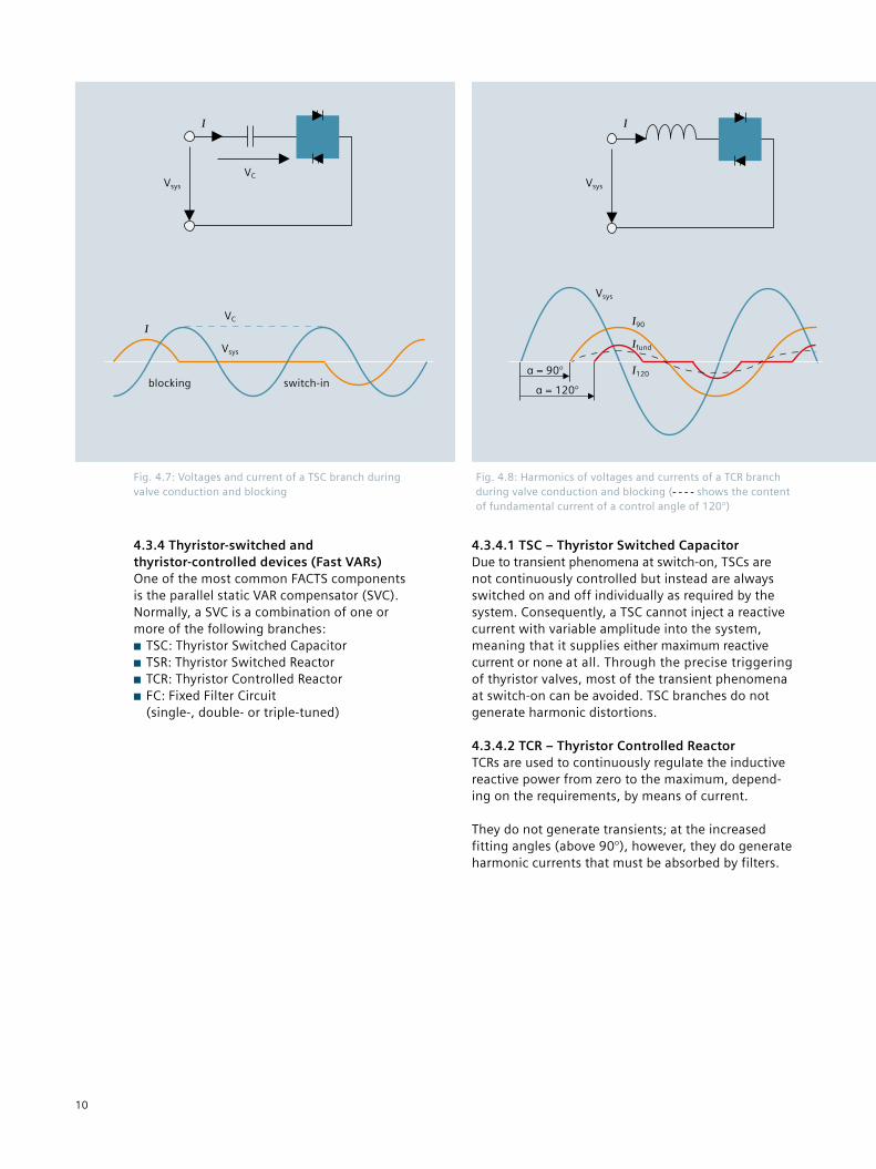
Fig. 4.7: Voltages and current of a TSC branch during valve conduction and blocking
I
VCVsys
IVC
Vsys
blocking switch-in
Fig. 4.8: Harmonics of voltages and currents of a TCR branch during valve conduction and blocking ( shows the content of fundamental current of a control angle of 120°)
I
Vsys
Vsys
I90
Ifund
I120α = 90°
α = 120°
4.3.4 Thyristor-switched and thyristor-controlled devices (Fast VARs)One of the most common FACTS components is the parallel static VAR compensator (SVC).Normally, a SVC is a combination of one or more of the following branches:■■ TSC: Thyristor Switched Capacitor■■ TSR: Thyristor Switched Reactor■■ TCR: Thyristor Controlled Reactor■■ FC: Fixed Filter Circuit (single-, double- or triple-tuned)
4.3.4.1 TSC – Thyristor Switched CapacitorDue to transient phenomena at switch-on, TSCs are not continuously controlled but instead are always switched on and off individually as required by the system. Consequently, a TSC cannot inject a reactive current with variable amplitude into the system, meaning that it supplies either maximum reactive current or none at all. Through the precise triggering of thyristor valves, most of the transient phenomena at switch-on can be avoided. TSC branches do not generate harmonic distortions.
4.3.4.2 TCR – Thyristor Controlled ReactorTCRs are used to continuously regulate the inductive reactive power from zero to the maximum, depend-ing on the requirements, by means of current.
They do not generate transients; at the increased fitting angles (above 90°), however, they do generate harmonic currents that must be absorbed by filters.
10
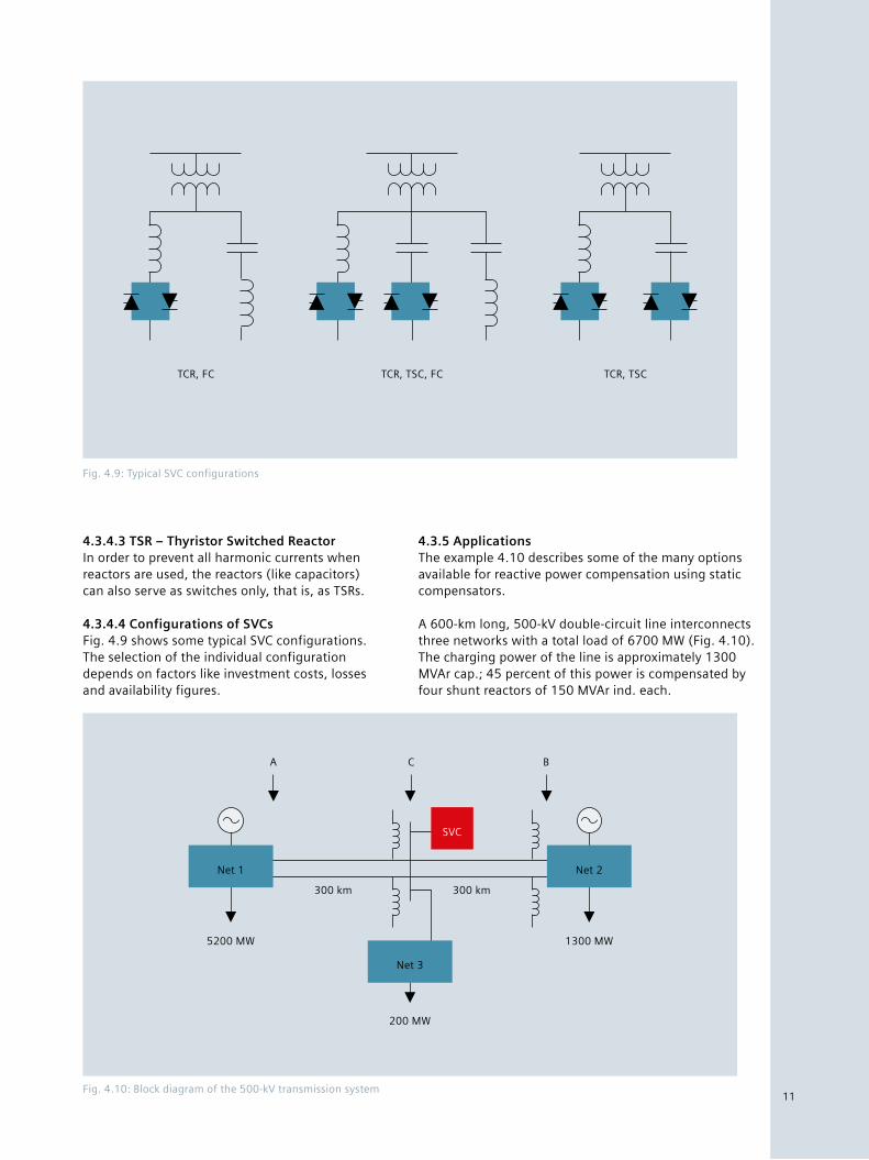
Fig. 4.10: Block diagram of the 500-kV transmission system
A C B
Net 2
1300 MW
SVC
Net 3
200 MW
Net 1
5200 MW
300 km 300 km
Fig. 4.9: Typical SVC configurations
TCR, FC TCR, TSC, FC TCR, TSC
4.3.4.3 TSR – Thyristor Switched ReactorIn order to prevent all harmonic currents when reactors are used, the reactors (like capacitors) can also serve as switches only, that is, as TSRs.
4.3.4.4 Configurations of SVCsFig. 4.9 shows some typical SVC configurations. The selection of the individual configuration depends on factors like investment costs, losses and availability figures.
4.3.5 ApplicationsThe example 4.10 describes some of the many options available for reactive power compensation using static compensators.
A 600-km long, 500-kV double-circuit line interconnects three networks with a total load of 6700 MW (Fig. 4.10). The charging power of the line is approximately 1300 MVAr cap.; 45 percent of this power is compensated by four shunt reactors of 150 MVAr ind. each.
11
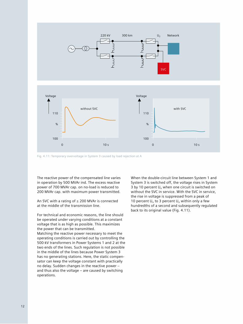
Fig. 4.11: Temporary overvoltage in System 3 caused by load rejection at A
Voltage
110
100
%
0 10 s
without SVC
Voltage
110
100
%
0 10 s
with SVC
220 kV 300 km U2 Network
SVC
The reactive power of the compensated line varies in operation by 500 MVAr ind. The excess reactive power of 700 MVAr cap. on no-load is reduced to 200 MVAr cap. with maximum power transmitted.
An SVC with a rating of ± 200 MVAr is connected at the middle of the transmission line.
For technical and economic reasons, the line should be operated under varying conditions at a constant voltage that is as high as possible. This maximizes the power that can be transmitted.Matching the reactive power necessary to meet the operating conditions is carried out by controlling the 500-kV transformers in Power Systems 1 and 2 at the two ends of the lines. Such regulation is not possible in the middle of the lines because Power System 3 has no generating stations. Here, the static compen-sator can keep the voltage constant with practically no delay. Sudden changes in the reactive power – and thus also the voltage – are caused by switching operations.
When the double-circuit line between System 1 and System 3 is switched off, the voltage rises in System 3 by 10 percent Un when one circuit is switched on without the SVC in service. With the SVC in service, the rise in voltage is suppressed from a peak of 10 percent Un to 3 percent Un within only a few hundredths of a second and subsequently regulated back to its original value (Fig. 4.11).
12
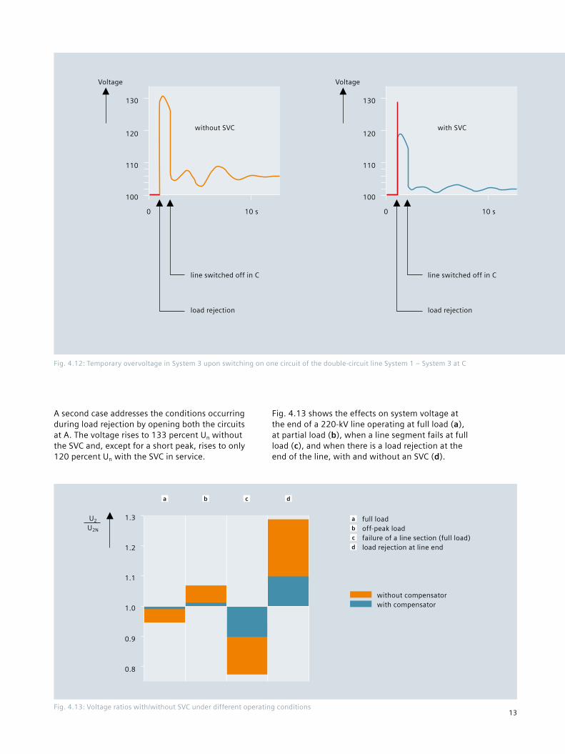
Fig. 4.13: Voltage ratios with/without SVC under different operating conditions
a b c d
1.3
1.2
1.1
1.0
0.9
0.8
U2 U2N
a full load b off-peak load c failure of a line section (full load) d load rejection at line end
without compensator with compensator
A second case addresses the conditions occurring during load rejection by opening both the circuits at A. The voltage rises to 133 percent Un without the SVC and, except for a short peak, rises to only 120 percent Un with the SVC in service.
Fig. 4.12: Temporary overvoltage in System 3 upon switching on one circuit of the double-circuit line System 1 – System 3 at C
Voltage
130
110
0
120
100
10 s
without SVC
load rejection
Voltage
130
110
0
120
100
10 s
with SVC
load rejection
Fig. 4.13 shows the effects on system voltage at the end of a 220-kV line operating at full load (a), at partial load (b), when a line segment fails at full load (c), and when there is a load rejection at the end of the line, with and without an SVC (d).
line switched off in C line switched off in C
13
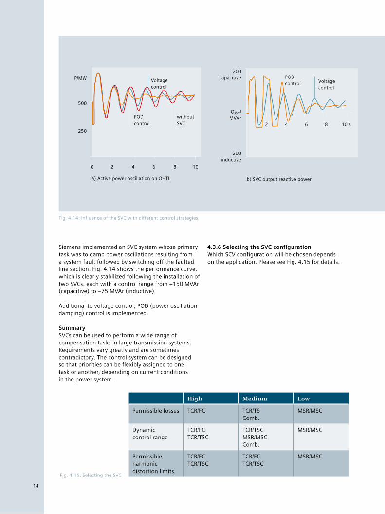
Siemens implemented an SVC system whose primary task was to damp power oscillations resulting from a system fault followed by switching off the faulted line section. Fig. 4.14 shows the performance curve, which is clearly stabilized following the installation of two SVCs, each with a control range from +150 MVAr (capacitive) to –75 MVAr (inductive).
Additional to voltage control, POD (power oscillation damping) control is implemented.
SummarySVCs can be used to perform a wide range of compensation tasks in large transmission systems. Requirements vary greatly and are sometimes contradictory. The control system can be designed so that priorities can be flexibly assigned to one task or another, depending on current conditions in the power system.
4.3.6 Selecting the SVC configurationWhich SCV configuration will be chosen depends on the application. Please see Fig. 4.15 for details.
Fig. 4.14: Influence of the SVC with different control strategies
250
0 2 4 6 8 10
500
Voltage control
POD control
without SVC
P/MW
a) Active power oscillation on OHTL
POD control Voltage
control
2 4 6 8 10 s
200 capacitive
200 inductive
QSVC/ MVAr
b) SVC output reactive power
Fig. 4.15: Selecting the SVC
High Medium Low
Permissible losses TCR/FC TCR/TS Comb.
MSR/MSC
Dynamic control range
TCR/FC TCR/TSC
TCR/TSC MSR/MSC Comb.
MSR/MSC
Permissible harmonic distortion limits
TCR/FC TCR/TSC
TCR/FC TCR/TSC
MSR/MSC
14
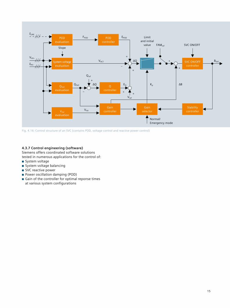
4.3.7 Control engineering (software)Siemens offers coordinated software solutions tested in numerous applications for the control of:■■ System voltage■■ System voltage balancing■■ SVC reactive power■■ Power oscillation damping (POD) ■■ Gain of the controller for optimal reponse times at various system configurations
Fig. 4.16: Control structure of an SVC (contains POD, voltage control and reactive power control)
ILINE
VHV~
IHV~
POD evaluation
System voltage evaluation
QSVC evaluation
VHV evaluation
POD controller
Q controller
Gain controller
Gain selector
Stability controller
SVC ON/OFF controller
FPOD EPOD
VACT
QSVC
Qref
∆Q
VHV
EQ
Vref
∆Q
Limit and initial
value FAMref SVC ON/OFF
BSVC
Kp ∆B
Normal/ Emergency mode
+
+
– ++
+
+–
Slope
+
15
4.4 SVC PLUS (STATCOM)Please refer to the separate available SVC PLUS brochure.
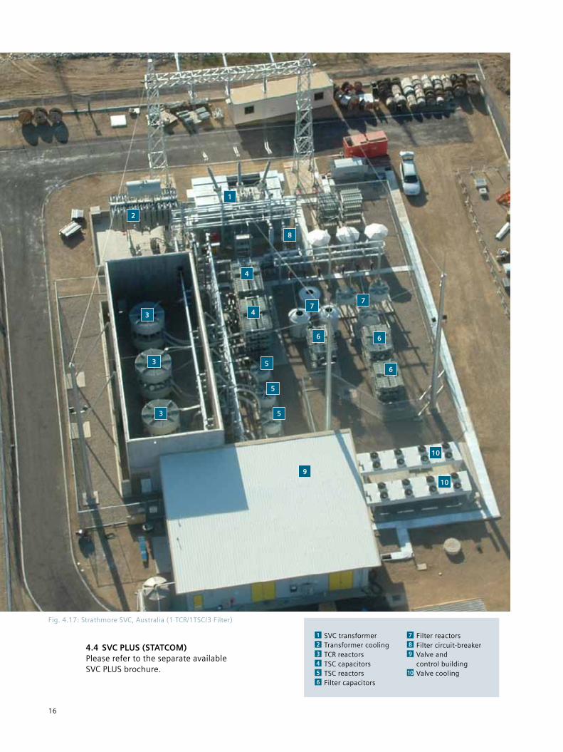
Fig. 4.17: Strathmore SVC, Australia (1 TCR/1TSC/3 Filter)
1
8
2
4
6
5
10
9
3
1 SVC transformer 2 Transformer cooling 3 TCR reactors 4 TSC capacitors 5 TSC reactors 6 Filter capacitors
7 Filter reactors 8 Filter circuit-breaker 9 Valve and control building 10 Valve cooling
4
3
3
5
5
6
77
6
10
16
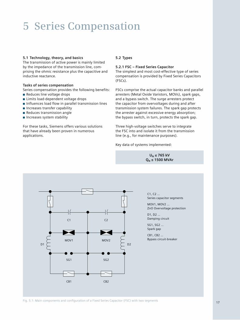
Fig. 5.1: Main components and configuration of a Fixed Series Capacitor (FSC) with two segments
5.1 Technology, theory, and basicsThe transmission of active power is mainly limited by the impedance of the transmission line, com- prising the ohmic resistance plus the capacitive and inductive reactance.
Tasks of series compensationSeries compensation provides the following benefits:■■ Reduces line voltage drops■■ Limits load-dependent voltage drops■■ Influences load flow in parallel transmission lines■■ Increases transfer capability■■ Reduces transmission angle■■ Increases system stability
For these tasks, Siemens offers various solutions that have already been proven in numerous applications.
5.2 Types
5.2.1 FSC – Fixed Series CapacitorThe simplest and most cost-effective type of series compensation is provided by Fixed Series Capacitors (FSCs).
FSCs comprise the actual capacitor banks and parallel arresters (Metal Oxide Varistors, MOVs), spark gaps, and a bypass switch. The surge arresters protect the capacitor from overvoltages during and after transmission system failures. The spark gap protects the arrester against excessive energy absorption; the bypass switch, in turn, protects the spark gap.
Three high-voltage switches serve to integrate the FSC into and isolate it from the transmission line (e.g., for maintenance purposes).
Key data of systems implemented:
UN ≤ 765 kVQN ≤ 1500 MVAr
5 Series Compensation
C1 C2
MOV1 MOV2
SG1 SG2
CB1 CB2
D1 D2
C1, C2 … Series capacitor segments
MOV1, MOV2 … ZnO Overvoltage protection
D1, D2 … Damping circuit
SG1, SG2 … Spark gap
CB1, CB2 … Bypass circuit-breaker
17
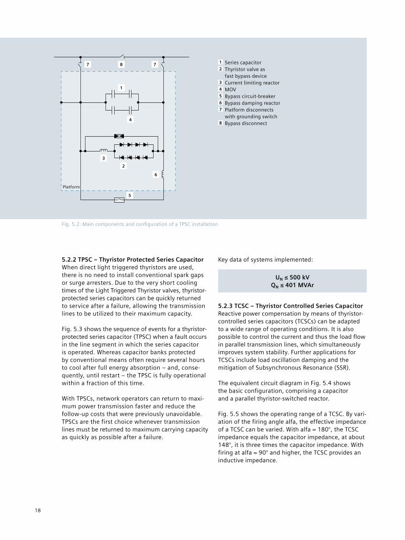
5.2.2 TPSC – Thyristor Protected Series CapacitorWhen direct light triggered thyristors are used, there is no need to install conventional spark gaps or surge arresters. Due to the very short cooling times of the Light Triggered Thyristor valves, thyristor-protected series capacitors can be quickly returned to service after a failure, allowing the transmission lines to be utilized to their maximum capacity.
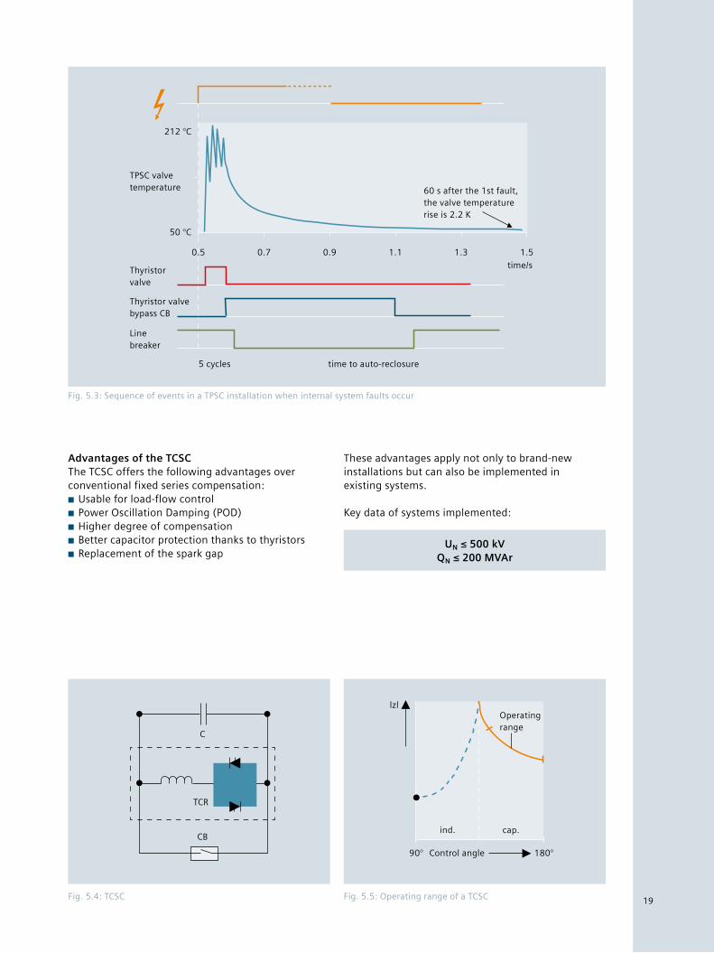
Fig. 5.3 shows the sequence of events for a thyristor-protected series capacitor (TPSC) when a fault occurs in the line segment in which the series capacitor is operated. Whereas capacitor banks protected by conventional means often require several hours to cool after full energy absorption – and, conse-quently, until restart – the TPSC is fully operational within a fraction of this time. With TPSCs, network operators can return to maxi-mum power transmission faster and reduce the follow-up costs that were previously unavoidable.TPSCs are the first choice whenever transmission lines must be returned to maximum carrying capacity as quickly as possible after a failure.
Key data of systems implemented:
UN ≤ 500 kVQN ≤ 401 MVAr
5.2.3 TCSC – Thyristor Controlled Series CapacitorReactive power compensation by means of thyristor-controlled series capacitors (TCSCs) can be adapted to a wide range of operating conditions. It is also possible to control the current and thus the load flow in parallel transmission lines, which simultaneously improves system stability. Further applications for TCSCs include load oscillation damping and the mitigation of Subsynchronous Resonance (SSR).
The equivalent circuit diagram in Fig. 5.4 shows the basic configuration, comprising a capacitor and a parallel thyristor-switched reactor.
Fig. 5.5 shows the operating range of a TCSC. By vari-ation of the firing angle alfa, the effective impedance of a TCSC can be varied. With alfa = 180°, the TCSC impedance equals the capacitor impedance, at about 148°, it is three times the capacitor impedance. With firing at alfa = 90° and higher, the TCSC provides an inductive impedance.
Fig. 5.2: Main components and configuration of a TPSC installation
1 Series capacitor 2 Thyristor valve as fast bypass device 3 Current limiting reactor 4 MOV 5 Bypass circuit-breaker 6 Bypass damping reactor 7 Platform disconnects with grounding switch 8 Bypass disconnect
Platform
1
2
3
4
5
6
7 78
18
Advantages of the TCSCThe TCSC offers the following advantages over conventional fixed series compensation:■■ Usable for load-flow control■■ Power Oscillation Damping (POD)■■ Higher degree of compensation■■ Better capacitor protection thanks to thyristors■■ Replacement of the spark gap
These advantages apply not only to brand-new installations but can also be implemented in existing systems.
Key data of systems implemented:
UN ≤ 500 kVQN ≤ 200 MVAr
Fig. 5.3: Sequence of events in a TPSC installation when internal system faults occur
212 °C
50 °C
0.5 0.7 0.9 1.1 1.3 1.5
time/s
60 s after the 1st fault, the valve temperature rise is 2.2 K
TPSC valve temperature
Thyristor valve
Thyristor valve bypass CB
Line breaker
5 cycles time to auto-reclosure
Fig. 5.4: TCSC Fig. 5.5: Operating range of a TCSC
C
TCR
CB
lzlOperating range
ind. cap.
90° 180°Control angle
19
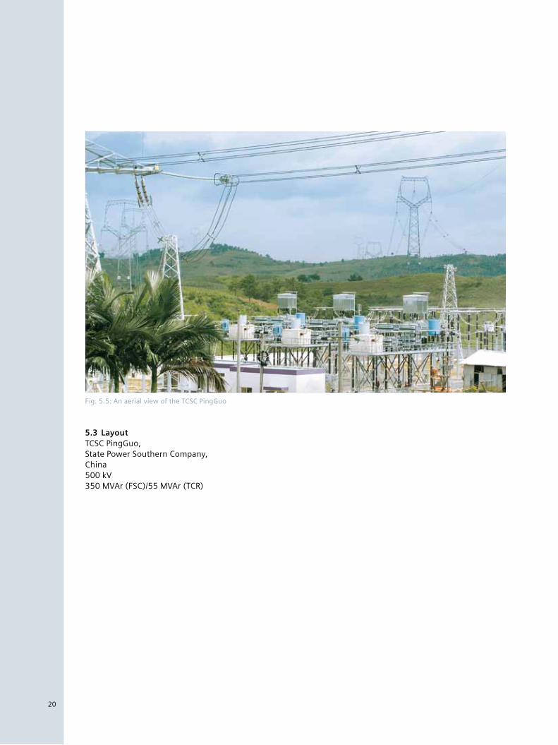
5.3 LayoutTCSC PingGuo, State Power Southern Company, China 500 kV 350 MVAr (FSC)/55 MVAr (TCR)
20
Fig. 5.5: An aerial view of the TCSC PingGuo
20
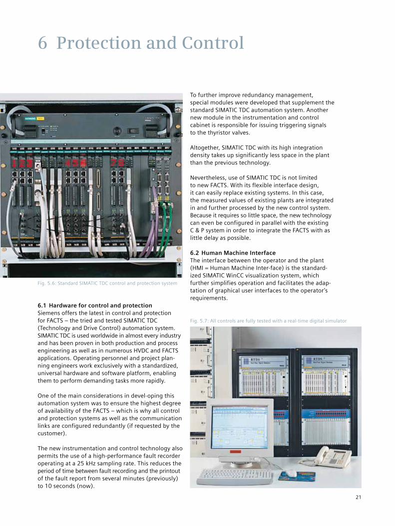
6.1 Hardware for control and protectionSiemens offers the latest in control and protection for FACTS – the tried and tested SIMATIC TDC (Technology and Drive Control) automation system. SIMATIC TDC is used worldwide in almost every industry and has been proven in both production and process engineering as well as in numerous HVDC and FACTS applications. Operating personnel and project plan-ning engineers work exclusively with a standardized, universal hardware and software platform, enabling them to perform demanding tasks more rapidly.
One of the main considerations in devel-oping this automation system was to ensure the highest degree of availability of the FACTS – which is why all control and protection systems as well as the communication links are configured redundantly (if requested by the customer).
The new instrumentation and control technology also permits the use of a high-performance fault recorder operating at a 25 kHz sampling rate. This reduces the period of time between fault recording and the printout of the fault report from several minutes (previously) to 10 seconds (now).
To further improve redundancy management, special modules were developed that supplement the standard SIMATIC TDC automation system. Another new module in the instrumentation and control cabinet is responsible for issuing triggering signals to the thyristor valves.
Altogether, SIMATIC TDC with its high integration density takes up significantly less space in the plant than the previous technology.
Nevertheless, use of SIMATIC TDC is not limited to new FACTS. With its flexible interface design, it can easily replace existing systems. In this case, the measured values of existing plants are integrated in and further processed by the new control system. Because it requires so little space, the new technology can even be configured in parallel with the existing C & P system in order to integrate the FACTS with as little delay as possible.
6.2 Human Machine Interface The interface between the operator and the plant (HMI = Human Machine Inter-face) is the standard-ized SIMATIC WinCC visualization system, which further simplifies operation and facilitates the adap-tation of graphical user interfaces to the operator’s requirements.
6 Protection and Control
Fig. 5.7: All controls are fully tested with a real-time digital simulator
Fig. 5.6: Standard SIMATIC TDC control and protection system
21
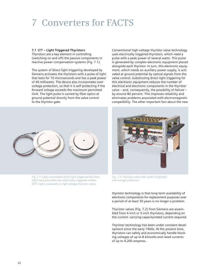
7.1 LTT – Light Triggered ThyristorsThyristors are a key element in controlling (switching on and off) the passive components in reactive power compensation systems (Fig. 7.1).
The system of direct light triggering developed by Siemens activates the thyristors with a pulse of light that lasts for 10 microseconds and has a peak power of 40 milliwatts. The device also incorporates over-voltage protection, so that it is self-protecting if the forward voltage exceeds the maximum permitted limit. The light pulse is carried by fiber optics at ground potential directly from the valve control to the thyristor gate.
Conventional high-voltage thyristor valve technology uses electrically triggered thyristors, which need a pulse with a peak power of several watts. This pulse is generated by complex electronic equipment placed alongside each thyristor. In turn, this electronic equip-ment, which needs an auxiliary power supply, is acti-vated at ground potential by optical signals from the valve control. Substituting direct light triggering for this electronic equipment reduces the number of electrical and electronic components in the thyristor valve – and, consequently, the possibility of failure – by around 80 percent. This improves reliability and eliminates problems associated with electromagnetic compatibility. The other important fact about the new
thyristor technology is that long-term availability of electronic components for replacement purposes over a period of at least 30 years is no longer a problem.
Thyristor valves (Fig. 7.2) from Siemens are assem-bled from 4-inch or 5-inch thyristors, depending on the current- carrying capacity/rated current required.
Thyristor technology has been under constant devel-opment since the early 1960s. At the present time, thyristors can safely and economically handle block-ing voltages of up to 8 kilovolts and rated currents of up to 4,200 amperes.
7 Converters for FACTS
Fig. 7.1: Easily assembled direct light triggered thyristors (left) have prevailed over electrically triggered models (ETT, right), especially in high-voltage thyristor valves
Fig. 7.2: Thyristor valve with wafer integrated overvoltage protection
22
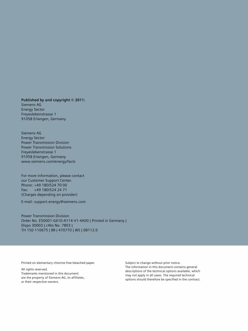
Complete solutions and services from a single sourceThe goal of modern power quality management is to provide stable, distortion-free voltage in a reliable manner. To this end, Siemens provides a single source for all the necessary FACTS equipment and a compre-hensive range of complementary services (Fig. 8.2), including basic system design, modeling, network analyses, civil works, project management, functional performance tests, delivery, and installation, as well as commissioning, on-site tests, and training of oper-ating personnel.
Siemens analyzes and calculates the power system requirements, develops customized solution concepts for complete system configurations and plants, and quickly implements them as turnkey systems. The delivery time for a typical SVC plant is from 15 to 24 months; FSC systems are ready to go in 10 to 15 months.
8 Complete Solutions
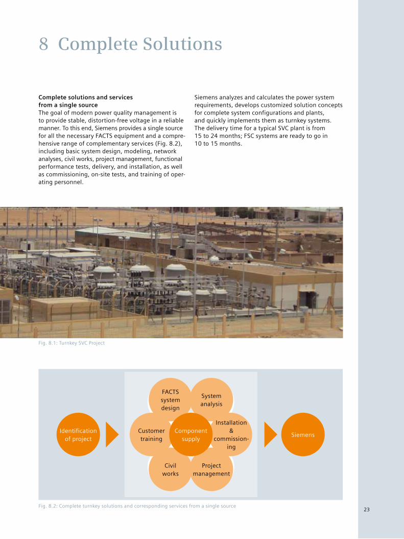
Fig. 8.1: Turnkey SVC Project
Fig. 8.2: Complete turnkey solutions and corresponding services from a single source
Identificationof project
Siemens
FACTSsystemdesign
Systemanalysis
Projectmanagement
Civilworks
Component supply
Installation &
commission-ing
Customertraining
23
Published by and copyright © 2011: Siemens AG Energy Sector Freyeslebenstrasse 1 91058 Erlangen, Germany
Siemens AG Energy Sector Power Transmission Division Power Transmission Solutions Freyeslebenstrasse 1 91058 Erlangen, Germany www.siemens.com/energy/facts
For more information, please contact our Customer Support Center. Phone: +49 180/524 70 00 Fax: +49 180/524 24 71 (Charges depending on provider)
E-mail: [email protected]
Power Transmission Division Order No. E50001-G610-A114-V1-4A00 | Printed in Germany | Dispo 30003 | c4bs No. 7803 | TH 150-110675 | BR | 470770 | WS | 08112.0
Printed on elementary chlorine-free bleached paper.
All rights reserved. Trademarks mentioned in this document are the property of Siemens AG, its affiliates, or their respective owners.
Subject to change without prior notice. The information in this document contains general descriptions of the technical options available, which may not apply in all cases. The required technical options should therefore be specified in the contract.


![Dynamic VAR Compensation using Static VAR Compensator · [2] Venkata Padmavathi.S. “Modeling and Simulation of Static Var Compensator to Enhance the Power System Security” conference](https://img.pdfslide.us/doc/110x75/5e7189d95c8ef147535b93c3/dynamic-var-compensation-using-static-var-2-venkata-padmavathis-aoemodeling.jpg)