Embed Size (px)
Citation preview

[email protected] © by CSP Products
499
XX
X 5
130V
DO
C:M
Features: - manufactured in Germany - CNC-machined from die cast aluminum - calipers with a piston diameter of 46.5mm - 22 versions with two different PCD´s are
available - stainless steel grease caps
Besonderheiten: - Hergestellt in Deutschland - CNC- bearbeitete Kokillen-Aluminium-Guß
Rohlinge - Bremsscheiben aus deutscher Fertigung - Schwimmsättel mit einem 46,5mm Kolben-
durchmesser eines deutschen Großserienher-stellers
- Momentan 22 Varianten mit zwei verschieden Lochkreisen lieferbar
- Nabenkappen aus Edelstahl
Disc Brake Kit 5-130, vented
Scheiben-Bremsanlage 5-130, innenbelüftet
Fit t ing Instruct ions Montageanlei tung
Version: 08/2016

[email protected] © by CSP Products
Version: 08/2016
1. General
NOTE: As when installing any performance product, a degree of mechanical abili-ty is required. If after reviewing the parts and instructions you don´t feel that you can properly complete this in-stallation, take your car to a compe-tent professional. Proper installation and adjustment will save time, money and aggravation.We recommend using this manual, to-gether with the applicable workshop manual for your car to help you with the installation.
WARNING: INCORRECT INSTALLATION OF THIS DISC BRAKE SYSTEM COULD RESULT IN VEHICLE DAMAGE, SERIOUS INJURY OR DEATH!
- Thank you for purchasing the CSP solid front disc brake system 5/130. Carefully installed, you'll really enjoy this brake system.
- These fitting instructions describes the in-stallation to the following models:Bug/Karmann Ghia pre 1965Bus 1950-1954Bus 1955-1963Bus 1964-1970Porsche 356A & 356B.
- Please use the checklist as soon as you un-pack your new kit. If something is missing call us up immediately.
- Before you start the job please take your time to read these instructions carefully. If you have any questions please call us at the given numbers.
- The kit includes all the parts that you'll need to convert your car to a solid front disc brake system with 5/130 bolt pattern.
- Only the adjusting nuts (Pos:2 in Fig.1) and
1. Allgemein
WICHTIG:Wie bei allen Fahrzeugteilen ist eine gewisse Sachkenntnis Vorausset-zung für eine korrekte Montage. Wenn sie nach Sichtung der Teile und der Montageanleitung nicht der Meinung sind die Montage durchführen zu kön-nen, wenden Sie sich an eine Fach-werkstatt um die Arbeiten ausführen zu lassen. Eine korrekte Montage und Einstellung spart Zeit, Kosten und Ärger.Wir empfehlen Ihnen diese Anleitung zusammen mit einem Reparaturhand-buch für Ihr Fahrzeug einzusetzen.
WICHTIG:Nach Durchführung der nachstehend beschriebenen Umrüstung erlischt die Betriebserlaubnis des Fahrzeuges! Die Abnahme gemäß §19 Abs 3. muss unverzüglich nach Montage er-folgen.
- Wir möchten Sie zu dem Kauf der CSP Scheiben-Bremsanlage innenbelüftet 5-130 beglückwünschen.Mit Sorgfalt montiert, werden Sie mit dieser Bremsanlage ein Menge Fahrspaß haben.
- In dieser Montageanleitung ist der Einbau für folgende Modelle beschrieben:Käfer/Karmann Ghia bis Bj. 1965Bus Bj. 1950-1954Bus Bj. 1955-1963Bus Bj. 1964-1970Porsche 356A & 356B
- Überprüfen Sie nach Erhalt der CSP-Bremsanlage die Vollständigkeit anhand der beigefügten Materialliste. Sollte entge-gen aller Erwartungen doch etwas fehlen, setzen Sie sich bitte unverzüglich mit uns in Verbindung.
- Nehmen Sie sich bitte die Zeit, und lesen Sie sich diese Montageanleitung sorgfältig durch,bevor Sie mit den Arbeiten beginnen. Bei Fragen oder Problemen stehen wir ger-ne telefonisch zur Verfügung.
- Der Lieferumfang der Bremsanlage beinhaltet sämtliche Teile, die Sie zur Umrüstung der Vorderachse auf Scheiben-bremse benötigen.Lediglich die Einstellmuttern (Pos:2 in
[email protected] © by CSP Products
Version: 08/2016
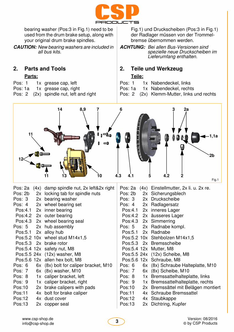
bearing washer (Pos:3 in Fig.1) need to be used from the drum brake setup, along with your original drum brake spindles.
CAUTION: New bearing washers are included in all bus kits.
2. Parts and Tools
Parts:
Pos: 1 1x grease cap, leftPos: 1a 1x grease cap, rightPos: 2 (2x) spindle nut, left and right
Pos: 2a (4x) damp spindle nut, 2x left&2x rightPos: 2b 2x locking tab for spindle nutsPos: 3 2x bearing washerPos: 4 2x wheel bearing setPos:4.1 2x inner bearingPos:4.2 2x outer bearingPos:4.3 2x wheel bearing seal
Pos: 5 2x hub assemblyPos:5.1 2x alloy hubPos:5.2 10x wheel stud M14x1,5Pos:5.3 2x brake rotorPos:5.4 12x safety nut, M8Pos:5.5 24x (12x) washer, M8Pos:5.6 12x allen hex bolt, M8
Pos: 6 6x (8x) bolt for caliper bracket, M10Pos: 7 6x (8x) washer, M10Pos: 8 1x caliper bracket, leftPos: 9 1x caliper bracket, rightPos:10 2x brake calipers with padsPos:11 4x bolt for brake caliperPos:12 4x dust coverPos:13 2x copper seal
Fig.1) und Druckscheiben (Pos:3 in Fig.1) der Radlager müssen von der Trommel-bremse übernommen werden.
ACHTUNG: Bei allen Bus-Versionen sind spezielle neue Druckscheiben im Lieferumfang enthalten.
2. Teile und Werkzeug
Teile:
Pos: 1 1x Nabendeckel, linksPos: 1a 1x Nabendeckel, rechtsPos: 2 (2x) Klemm-Mutter, links und rechts
Pos: 2a (4x) Einstellmutter, 2x li. u. 2x re.Pos: 2b 2x SicherungsblechPos: 3 2x DruckscheibePos: 4 2x RadlagersatzPos:4.1 2x inneres LagerPos:4.2 2x äusseres LagerPos:4.3 2x Simmerring
Pos: 5 2x Radnabe kompl.Pos:5.1 2x RadnabePos:5.2 10x Stehbolzen M14x1,5Pos:5.3 2x BremsscheibePos:5.4 12x Mutter, M8Pos:5.5 24x (12x) Scheibe, M8Pos:5.6 12x Schraube, M8
Pos: 6 6x (8x) Schraube Halteplatte, M10Pos: 7 6x (8x) Scheibe, M10Pos: 8 1x Bremssattelhalteplatte, linksPos: 9 1x Bremssattelhalteplatte, rechtsPos:10 2x Bremssättel mit Belägen montiertPos:11 4x Schraube BremssattelPos:12 4x StaubkappePos:13 2x Dichtring, Kupfer
Fig.15
1,1a
2b
2a3
24.24.3 4.110
678,914
1311
12
11
[email protected] © by CSP Products
Version: 08/2016
Pos:14 (2x) spindle with spigot ringPos:15 2x brake hosePos:16 1x LoctitePos:17 1x mounting tool
Tools:
1x 11mm combination wrench1x 14mm combination wrench1x 17mm combination wrench1x 19mm combination wrench1x 24mm combination wrench1x 8mm allen hex key1x 6mm allen hex key1x 19mm socket1x ratchet 1x torque wrench1x plastic hammer1x wire brush
brake fluidbrake cleanercleaning rag
3. Installation
3.1. Spindles
NOTE: The CSP-brake-system is engineered to work with drum brake spindles only.
- To fit this disc brake system to the front of your car, your spindles must meet the fol-lowing requirements:
-Check that the spindle isn´t worn. For measuring the spindle see Fig.2 and Tab.1.
-When you have a link pin axle, make sure that the king & link pins aren´t worn.See your workshop manual for details.
-Check spindle and backing plate mounting area for any rust or damage.
Pos:14 (2x) Achsschenkel mit DistanzringPos:15 2x BremsschlauchPos:16 1x SchraubensicherungsmittelPos:17 1x Kunststoff-Dorn
Werkzeug:
1x Ring-Maulschlüssel SW111x Ring-Maulschlüssel SW141x Ring-Maulschlüssel SW171x Ring-Maulschlüssel SW191x Ring-Maulschlüssel SW241x Nuß Innensechskant 8mm1x Nuß Innensechskant 6mm1x Nuß, SW191x Umschaltknarre1x Drehmomentschlüssel1x Kunststoffhammer1x Drahtbürste
BremsflüssigkeitBremsenreinigerPutzlappen
3. Voraussetzungen
3.1. Achsschenkel
WICHTIG:Es können grundsätzlich nur Trommelbrems-Achsschenkel zum Aufbau der CSP-Scheibenbremsanla-ge verwendet werden.
- Die Achsschenkel, die zum Aufbau der CSP-Bremse verwendet werden sollen, müssen bestimmte Anforderungen erfüllen:
-Die Radlagersitze dürfen nicht verschlissen sein! Überprüfen Sie bitte genau die Ober-flächen der Radlagersitze auf Beschädi-gungen. Für die maßliche Überprüfung der Lagersitz-Durchmesser haben wir Ihnen die Toleranzmaße in einer Tabelle zusam-men gestellt. Siehe Fig.2 und Tab. 1.
-Bei Bundbolzenachsen ist auf den ein-wandfreien Zustand der Achsschenkelbol-zen sowie der Bundbolzen zu achten!Die Beurteilungskriterien entnehmen Sie

[email protected] © by CSP Products
Version: 08/2016
3.2. Master cylinder (m/c)
CAUTION: It is essential to use a master cylin-der designed for disc brakes.
WARNING: If you use the front disc brake sys-tem with a drum brake master cylin-der, the built-in residual pressure valve will cause a steady pressure at the front wheel, causing them to drag, overheat and become damaged.
- Please note that all vehicles with drum brakes at the front need to change the mas-ter cylinder to a disc-brake type.
- Bug, Karmann GhiaThe disc brake master cylinder with part number 611 015 000 (RHD: 611 016 000) can be installed very easily when using the adapter kit 611 017 111 (RHD: 611 018 111)
bitte Ihrem Fahrzeug-Reparaturleitfaden.
-Auch der Bereich des Achsschenkelzap-fens wo der Simmerring des inneren Radla-gers anliegt muß auf Beschädigungen überprüft werden.
3.2. Hauptbremszylinder (HBZ)
WICHTIG: Es ist sehr wichtig, dass Ihr Fahr-zeug mit einem HBZ für Scheiben-bremse ausgerüstet ist!
ACHTUNG: Sollten Sie die CSP-Scheiben-bremse mit einem HBZ für Trom-melbremse benutzen, wird durch das im HBZ eingebaute Bodenven-til ein Vordruck erzeugt, der zu einem ständigen Bremsen und so-mit zu einer Überhitzung und Be-schädigung der Bremsanlage führt.
- Grundsätzlich muss bei allen Fahrzeugen mit Trommelbremse an der Vorderachse der Trommelbrems-HBZ gegen einen Scheibenbrems-HBZ ausgetauscht wer-den.
- Käfer,Karmann GhiaDer Einbau eines Scheibenbrems-HBZ ist beim Käfer, Karmann Ghia und Kübel pro-blemlos mit dem Hauptbremszylinder Best-Nr. 611 015 000 und dem Montagesatz Best-Nr. 611 017 111 möglich.
Tab.1
ModelModell
Bearing Seat TolerancesLagersitz-Toleranzen
Bug/Karmann Ghia -65with link pin axle
A: 24,99-25,00mm / 0.9837-0.9843 in.
Käfer/Karmann Ghia -65mit Bundbolzenachse
B: 19,98-19,99mm / 0.7866-0.7870 in.
Bus 50-63 A: 29,987-30,000mm / 1.1806-1.1811 in.
Bus Baujahr 1950-1963 B: 24,987-25,000mm / 0.9837-0.9843 in.
Bus 64-70 A: 31,733-31,745mm / 1.2493-1.2498 in.
Bus Baujahr 1964-1970 B: 19,033-19,045mm / 0.7493-0.7498 in.
Porsche 356A A: 24,99-25,00mm / 0.9837-0.9843 in.
B: 19,98-19,99mm / 0.7866-0.7870 in.
Porsche 356B A: 29,984-30,000mm / 1.1805-1.1811 in.
B: 19,980-19,993mm / 0.7866-0.7871 in. Fig.2
A B

[email protected] © by CSP Products
Version: 08/2016
- BusOn 1950-1967 buses the adapter kit 611 015 267 can be used to install the disc brake master cylinder 611 021 211AA. This m/c is normally used on buses 1971-1979.
- Porsche 356A und BThe master cylinder needs to be changed to the disc brake master cylinder 611 015 356. All necessary hardware is supplied with this master cylinder.
3.3. Wheels
- Generally this CSP-disc brake kit 5-130 is designed for 15" wheels.
4. Preparing the car
- Park your car on an even surface in your workshop. Loosen your front wheel bolts and raise your car with a jack at the right po-sition till the front wheels rotate free. Secure the car with some Axle stands.
- Remove the wheels. The original brake system needs to be stripped to the spindles.
- Empty the hydraulic system.
NOTE: Please note that the thrust washer and the adjusting nut are needed with the CSP-brake system. On Buses 50-70 only the adjusting nuts are reused.
NOTE: Please make sure that the spigot ring remains on the spindle on all Type-1 pre 65, Porsche 356, Type-2 pre 63 and Type-2 68-70 applications.
5. Installation
- BusBeim Bus Baujahr 1950-1967 muss auf den Scheibenbrems-HBZ aus dem Bus Baujahr 1971-1979 mit der Best-Nr. 611 021 211AA und dem passenden Einbausatz Best-Nr. 611 015 267 umgerüstet werden.
- Porsche 356A und BBeim Porsche 356A und B muss ebenso der Originale HBZ gegen eine Version für Scheibenbremsen ausgetauscht werden. Wir empfehlen Ihnen unseren HBZ mit der Best-Nr. 611 015 356 da er mit Montage-material für 356’er geliefert wird.
3.3. Felgen
- Grundsätzlich ist die CSP-Scheibenbrems-anlage 5-130 für den Betrieb mit 15-Zoll Felgen konstruiert.
4. Vorbereitung des Fahrzeuges
- Stellen Sie Ihr Fahrzeug auf einer ebenen Fläche in Ihrer Werkstatt ab. Lösen Sie die vorderen Radschrauben und heben Sie das Auto mittels eines Wagenhebers an geeig-neter Stelle an, bis die Vorderräder frei dre-hen. Sichern Sie das Fahrzeug mittels Unterstellböcke gegen Herabsinken.
- Demontieren Sie die Räder. Die Serien-bremsanlage muss nun bis auf die Achs-schenkel demontiert werden. Entleeren Sie dazu das Bremssystem und führen Sie die alte Bremsflüssigkeit einer sachgerechten Entsorgung zu.
ACHTUNG: Die Druckscheiben für die äußeren Radlager sowie die Einstellmuttern werden für die neue CSP-Brems-anlage wieder benötigt. Diese Teile bitte sorgfältig aufbe-wahren.Ausnahme ist der Bus, wo spezielle neue Druckscheiben im Lieferun-fang enthalten sind.
WICHTIG: Da Sicherungsbleche nur eimalig benutzt werden dürfen, müssen hier die Alten entsorgt werden.

[email protected] © by CSP Products
Version: 08/2016
5.1. Caliper bracket
- It is obvious that the use of a disc brake system requires brake calipers. To mount these calipers to your drum brake spindles, a special caliper bracket is installed to the original spindle with high grade allen head screws.
- Make sure that the surface on the spindle where the caliper bracket is to be bolted to is very clean!
WARNING: Clean the mounting surface on the spindle very carefully!
- Usually this area is very rusty so you should
take your time to clean the mounting sur-face. This can be done with a wire brush.
- The desired surface is shown in Fig.3.- The tapped holes of the mounting surface
are to be examined and cleaned carefully.
NOTE: Successful brake system installation and function depends on the proper preparation and mounting of the cali-per bracket!
WARNING: If your spindles have to be paint-ed, you have to install the caliper bracket before painting!! Otherwise the paint between the spindle and the bracket will cause problems with the brake perfor-mance.
5. Montage der Bremse
5.1. Bremsattelhalteplatte
- Um einen Bremssattel an einem Trommel-brems-Achsschenkel zu befestigen, benö-tigt man eine spezielle Halteplatte. Diese Bremssattelhalteplatte wird mittels hochfester Schrauben an den Befesti-gungspunkten der Bremsankerplatte montiert.
WICHTIG:Hierbei ist peinlichst darauf zu achten, dass die Kontaktflächen zwischen Achsschenkel und Bremssattelhalte-platte sauber sind!!
- In der Regel ist die Anschraubfläche bei gebrauchten Achsschenkeln sehr verrostet und muss mit geeigneten Mitteln (z.B. Drahtbürste/Schaber) soweit gereinigt wer-den, dass die Anschraubfläche metallisch rein ist.
ACHTUNG: Gehen Sie bei der Reinigung der in Fig.3 gezeigten Fläche sehr sorg-fältig vor, denn die reibungslose Funktion der CSP-Bremsanlage hängt im Wesentlichen von der Montage der Halteplatte ab!
WICHTIG:Die Anschraubfläche darf nicht lackiert, gepulvert, gewachst oder geölt werden! Sie muß metallisch rein sein!
Fig.3
Bug/Käfer -65,Karmann Ghia -65,Porsche 356A/B
Bug/Käfer 66-,Karmann Ghia 66-,Thing/Kübel
Bus 50-70 Type-3 / Typ-3

[email protected] © by CSP Products
Version: 08/2016
- When the mounting surface is rust-free & clean, the bracket can be installed with three or four M10 bolts using a washer and loctite shown in Fig.4.On all Bug, Karmann Ghia and Porsche 356A/B application you need to tighten three bolts up to a torque of 73Nm(54ft/lbs).Buses use four mounting bolts that need to be torqued to 73Nm (54ft/lbs) as well.
CAUTION: The caliper mounting bolts need to be loctited in place. The necessary loctite is supplied with the brake system hardware.
CAUTION: Be careful on the bus kit!! The caliper bracket can be installed in two, 180° different, positions. The correct position is when the two holes for mounting the caliper are in driving direction behind the spindle.
- Auf die saubere, metallisch reineAnschraubfläche des Achsschenkels wird jetzt mit den hochfesten Innensechskant-schrauben M10x20 und U-Scheibe die Bremssattelhalteplatte montiert siehe Fig.4.Beim Käfer/Karmann Ghia und Porsche 356A/B sind es drei Schrauben die mit ei-nem Drehmoment von 73 Nm angezogen werden. Beim Bus sind es 4 Schrauben die auch mit einem Drehmoment von 73 Nm angezogen werden.
ACHTUNG: Die Halteschrauben müssen mit Schraubensicherungsmittel einge-setzt werden.Das Schraubensicherungsmittel ist im Lieferumfang enthalten.
WICHTIG:Beim Bus können theoretisch die Bremssattelhalteplatten um 180° ver-dreht angebaut werden. Für die richtige Funktion muss der Bremssattel in Fahrtrichtung gesehen hinten angebracht werden.
Fig.4

[email protected] © by CSP Products
Version: 08/2016
5.2. Aluminum hub with rotor
- The alloy hub and rotors are pre-assembled by CSP, as are the wheel bearings.
CAUTION: The wheel studs are pre-installed by CSP and must not be removed under any circumstance. You will lose any guarantee when removing the studs.
CAUTION: In case of replacing worn discs please note that the six mounting bolts need to replaced also.
WARNING: If you are changing the discs, it is necessary to equally torque all mounting bolts to 32Nm (24ft/lbs) to avoid any chance of the disc not be-ing true.
- To install the hub with rotor on the spindle, the inner wheel bearing (Pos:4.1, Fig.1) has to be installed with the right amount of grease.
- Press in the seal (Pos:4.3, Fig.1) into the rear of the alloy hub.
- Make sure that the surface the seal runs on the spindle is free of damage and paint. Oil slightly.
NOTE: Bus kits with the part number 499 264 5130 will be supplied with two different size wheel bearing seals. The seal with the 45mm inner diameter need to be used on Buses 64-67 while the 50mm seal will fit 68-70 applications. So make sure you choose the correct seal before they are pressed into the hub assembly.
- Place the hub on the spindle and install the outer bearing (Pos:4.2, Fig.1) with plenty of grease.
- Install the bearing washer (Pos:3, Fig.1) and the spindle nut (Pos:2, Fig.1) or the hex spindle nuts (Pos:2a, Fig.1) with the locking tab (Pos:2b, Fig.1).
- Adjust the wheel bearing to manufacturer specifications. Please refer to your original workshop manual for the correct procedure which needs to be carefully followed.
5.2. Radnabe mit Bremsscheibe
- Die Radnaben mit Bremsscheiben sind von uns bereits vormontiert, d.h. die Radlager-schalen sind eingepresst, die Stehbolzen sind in der Nabe montiert und die Brems-scheibe ist mit Hilfe der sechs Befesti-gungsschrauben an der Radnabe befestigt.
ACHTUNG: Die Stehbolzen zur Befestigung der Felge sind unsererseits vormontiert und dürfen unter keinen Umstän-den entfernt werden! Sollten Sie die Radbolzen aus irgendeinem Grund entfernen, so entfällt jegli-cher Garantieanspruch!
ACHTUNG: Sollten die Bremsscheiben einmal erneuert werden, müssen auch die Befestigungsschrauben und Mut-tern erneuert werden.
WICHTIG: Für den korrekten Sitz der Brems-scheibe ist es sehr wichtig, dass alle 6 Befestigungsschrauben mit dem gleichen Drehmoment von 32 Nm angezogen werden!
- Zur Montage der Radnabe auf dem Achs-schenkel muß zuerst das innere Radlager (Pos:4.1, Fig.1) mit ausreichend Radlager-fett in die Radnabe eingesetzt werden.
- Pressen Sie nun den Simmerring (Pos:4.3, Fig.1) bündig in die hintere Bohrung der Radnabe.
ACHTUNG: Beim Bus Kit 499 264 5130 sind 2 , in der Größe unterschiedliche, Sim-merring-Paare dabei. Das Paar mit dem 50mm Innendurchmesser ist für die Baujahre 68-70, das andere Paar (45mm) für die Baujahre 64-67.
- Stülpen Sie die Radnabe mit innerem Rad-lager und Simmerring über den Achsschen-kelzapfen, bis zum Anschlag.
- Setzen Sie das äußere Radlager (Pos:4.2, Fig.1) mit reichlich Radlagerfett ein.
- Anschließend setzen Sie die Druckscheibe (Pos:3, Fig.1) auf den Achsschenkelzapfen und sichern sie entweder mit der Klemm-mutter (Pos:2, Fig.1) oder den 2 Einstell-muttern (Pos:2a, Fig.1) und einem Sicherungsblech (Pos:2b, Fig.1) .
- Stellen Sie das Radlagerspiel gemäß der Herstellerangabe aus Ihrem Fahrzeug-Re-paraturleitfaden ein.

[email protected] © by CSP Products
Version: 08/2016
- Don't forget to secure the adjusting nut.- The grease cap (Pos:1/1a, Fig.1) can be in-
stalled at this point. Make sure that the cap with the hole goes on the left side of the car.
- If you have removed the speedometer cable, now is the time to get it back in the spindle.
5.3. Caliper
- Before installing the brake caliper (Pos:15, Fig.1) , you should make sure that the rotor is free of oil or grease. Clean the rotor with a suitable cleaning fluid before mounting the caliper.
- The calipers are left and right handed. The picture Fig.6 shows you how the pads are installed correctly. Check that the springs are fitted correctly.
WARNING: The caliper is of a sliding design; please do not be tempted to slide the caliper apart too far as the two halves will become seperated.
WARNING: Please check the bleeder screws. They have to point upwards. Other-wise you will not be able to bleed your system!See Fig.6
- Install the caliper to the caliper bracket with the two M12x1.5 high grade bolts (Pos:16, Fig.1) and torque them up to 78Nm.Make sure to use the supplied Loctite on the threads ends of the mounting bolts.
- Vergessen Sie nicht, die Klemmutter fest-zuziehen bzw. das Sicherungsblech umzu-schlagen.
- Montieren Sie jetzt die Nabenkappe (Pos:1/1a, Fig.1) auf die Radnabe. Achten Sie hierbei darauf, dass die Kappe mit dem Loch für den Tachoantrieb auf der linken Fahrzeugseite montiert wird.
- Sollten Sie Ihre Tachowelle aus der Achs-schenkelbohrung entfernt haben, so ist nun der passende Moment gekommen, um die Tachowelle wieder korrekt zu montieren.
5.3. Bremssattel
- Vor der Montage des Bremssattels (Pos:15, Fig.1) sollten Sie sicherstellen, dass die Bremsscheibe frei von Öl oder Fettrückständen ist. Reinigen Sie die Bremsscheibe ggf. mit einer geeigneten Reinigungsflüssigkeit wie z.B. Bremsenreiniger.
- Montieren Sie die Bremsbeläge im Sattel wie in Fig.6 gezeigt. Achten Sie auf den richtigen Sitz der Federn.
ACHTUNG: Der Bremssattel braucht und darf nicht auseinander gebaut werden!
WICHTIG:Die Entlüfterschraube am Bremssattel muss nach oben zeigen, ansonsten sind Sie nicht in der Lage Ihr Bremssystem zu entlüften.
Siehe Fig.5
- Montieren Sie den Brems-sattel mit Bremsbelägen an der Bremssattelhalte-platte mit den M12x1,5 Feingewindeschrauben (Pos:16, Fig.1). Die Gewinde müssen mit dem mitgelieferten Schraubensicherungsmit-tel benetzt werden. An-schliessend sind die Schrauben mit einem Drehmoment von 78 Nm anzuziehen.
Fig.5

[email protected] © by CSP Products
Version: 08/2016
CAUTION:Adjust the pad gap only to rotor thick-ness, to avoid any possible problems when installing your wheels.
CAUTION:Remember any possible spacers that are installed between brake cali-per and the caliper bracket.See following chart for details.
- Press the dust covers over the caliper bolts. This is done with the special installation tool (see Fig.7) that is supplied with the kit.
- In case you need replacement covers, these are available individually under Part-# 611 485 000.
NOTE: Be sure to keep the tool for later use if you ever need to remove and replace the covers again.
5.4. Brake hoses
- The brake hose will be srewed directly into the caliper. Don’t forget to use the thin cop-per washer between the hose and the cali-per
- The other side of the brake hose is installed like the original hose.
ACHTUNG:Drücken Sie die Bremsbeläge nur soweit ausein-ander wie die Bremsscheibe stark ist. Um den Bremssattel optimal montieren zu können.
ACHTUNG:Beachten Sie die Distanzscheiben, die ggf. zwi-schen Bremssattel und Halteplatte gehören. Sie-he folgende Tabelle.
- Setzen Sie die Staubkappen auf die Brems-sattelschrauben. Benutzen Sie, wie in Fig.6 gezeigt, den mit-gelieferten Kunststoff-Dorn zum Montieren.
- Die Staubkappen sind auch als Ersatzteil unter der Best.-Nr. 611 485 000 erhältlich.
WICHTIG:Der Kunststoff-Dorn sollte für spätere Ver-wendungen (z.B. Brems-scheibenwech-sel) aufbewahrt werden!
5.4. Bremsschläuche
- Die Abdichtung des Bremsschlauches am Bremssattel erfolgt mit Hilfe eines Kupfer-Dichtring.
- Fahrzeugseitig muss die originale Haltevor-richtung verwendet werden.
Fig.6

[email protected] © by CSP Products
Version: 08/2016
CAUTION: Make sure that the hoses do not get in contact with any rotating parts and that the hoses are not twisted.
Repeat steps 5.1 to 5.5 for the other side of the car.
6. Master cylinder
- As already mentioned in chapter 3.2 it is very important to convert your car to a disc brake master cylinder.
- For the solid CSP-disc brakes we recom-mend a master cylinder with a piston diam-eter:- 20.64mm for Bug/Karmann Ghia.- 24mm for Bus.
- In the chart Tab.2 you find a complete over-view of the correct m/c and their mounting
hardware.- Make sure you use a correct master cylin-
der with your CSP solid front disc brakes. Further information is supplied with the master cylinder adapter kit installation in-structions.
- After mounting the CSP-disc brakes and master cylinder the brake system can be bled.
7. Wheels
- Our alloy hubs are delivered with wheel studs M14x1.5 installed. So in nearly all ap-plications it is necessary to change from bolts to nuts.
ACHTUNG: Achten Sie darauf, dass die Brems-schläuche nicht verdreht eingebaut werden. Ebenso muss die Frei-gängigkeit zu drehenden Teilen ge-währleistet sein!
Wiederholen Sie die Schritte 5.1 - 5.5 um die andere Fahrzeugseite zu montieren.
6. Hauptbremszylinder (HBZ)
- Wie schon im Kapitel 3.2 erwähnt ist es sehr wichtig Ihr Fahrzeug mit dem richtigen HBZ auszurüsten.
- Wir empfehlen Ihnen für die Vollscheiben-Bremsanlage einen HBZ mit einem Kolben-durchmesser von:- 20,64mm für Käfer/Karmann Ghia.- 24mm für Bus.
- In der Tabelle Tab.2 finden Sie eine kom-plette Übersicht der richtigen HBZ’s mit den
dazu passenden Montagesätze.- Nachdem die CSP-Bremsanlage und der
richtige Hauptbremszylinder montiert wor-den sind, kann die Bremsanlage wieder mit Bremsflüssigkeit befüllt und entlüftet wer-den. Hierbei können Sie in ähnlicher Weise vorgehen wie es in Ihrem Fahrzeug-Repa-raturleitfaden beschrieben ist.
7. Radbefestigung
- Da die Radnaben mit Stehbolzen M14x1,5 ausgerüstet sind, ist es in fast allen Anwen-dungen notwendig, dass Sie die vorderen Radschrauben gegen Radmuttern wech-seln müssen.
Tab.2
ModelModell
Master Cylinder (MC)Hauptbremszylinder (HBZ)
Mounting Hardware for MCMontagesatz für HBZ
Bug/Karmann Ghia, LHD #: 611 015 000 #: 611 017 111
Käfer/Karmann Ghia, Linkslenker
Bug/Karmann Ghia, RHD #: 611 016 000 #: 611 018 111
Käfer/Karmann Ghia, Rechtslenker
Bus 50-67, LHD & RHD #: 611 021 211AA #: 611 015 267
Bus Baujahr 1950-1967, LHD & RHD
Porsche 356A/356B, LHD & RHD #: 611 015 356 not necessary
Porsche 356A/356B,Links-&Rechtslenker keiner notwendig

[email protected] © by CSP Products
Version: 08/2016
NOTE: The studs are loctited into place and must not be removed! In nearly all ap-plications the wheel bolts or nuts have to be changed to match the M14x1,5 thread.
- Be sure to choose the right nuts that match the seat in the rim.The most common are shown in the chart Tab.3.
CAUTION: The wheel nuts must be torque to 110Nm / 81 ft/lbs. See Tab.5.
CAUTION: Don't forget to retighten the nuts after 50mls !
8. Torque Chart
- Make sure all bolts and nuts are torqued to the correct amount.
CAUTION: See the following chart Tab.5 for de-tails.
WICHTIG:Achten Sie darauf, dass Sie genau die richtigen Radmuttern für Ihre Felgen benutzen. Siehe Tab.3.
- Hierbei wird unterschieden zwischen Fel-gen mit Kugel- oder Kegelsitz. Die Kugel-sitz Felgen können weiterhin in der Ausführung des Kugelradius variieren.
WICHTIG:Die Radmuttern werden mit einem Drehmoment von 110Nm angezogen!Siehe auch Tabelle Tab.5.
WICHTIG:Bitte vergessen Sie nicht nach 50km die Radmuttern nachzuziehen!
8. Anzugsdrehmomente
- Es ist sehr wichtig die Schrauben und Muttern der CSP-Vollscheibenbremse mit dem richtigen Drehmoment anzuziehen.Die Tabelle Tab.4 gibt Ihnen die einzelnen Drehmomente an.
Tab.3
WheelFelge
Ball seat M14x1,5 R14M14x1,5 Kugelbund R14
Tapered M14x1,5 60°M14x1,5 Kegelbund 60°
Gasburner (Repro) X
Porsche Fuchs (Repro) X
Partnumber:Bestellnummer:
601 143 001 601 143 002C
BoltSchraube
DimensionsAbmessung
Torque in NmDrehmoment in Nm
Torque in ft/lbsDrehmoment in ft/lbs
CaliperM12x1,5x45mm 78 58
Bremssattel
Caliper BracketM10x20mm 73 54
Bremssattelhalteplatte
Caliper Bracket, Type-3/34 M10x1x20 / M10x1x55& M10 Nut / Mutter 77 57
Bremssattelhalteplatte, Typ-3/34
RotorM8x50mm 32 24
Bremsscheibe
Wheel NutM14x1,5 110 81
Radmutter
Brake Hose AdapterM10 25 30
Adapter Bremsleitung
Tab.4

[email protected] © by CSP Products
Version: 08/2016
9. Overall width change
- A result in installing the CSP-disc brake system is an overall width changing.
- The change in width is show below in the chart Tab.4:
9. Spurveränderung
- Durch die Montage der CSP-Vollscheiben-bremsanlage ergibt sich eine Änderung der Spurbreite.
- Die folgende Tabelle Tab.5 gibt Ihnen ge-naue Auskunft über die Spuränderung an Ihrem Fahrzeug.
Tab.5
ModelFahrzeug
Width Change (per side)Spuränderung pro Seite
compared togemessen gegenüber
Bug/Karmann Ghia -65with ball joint axle, (ZeroOffset Version)
+3,5 mm Brake Drum 58-65Bremstrommel 58-65
Bus 50-54+7 mm
Brake Drum 50-54Bremstrommel 50-54Bus Baujahr 1950-1954
Bus 55-63-2,5 mm
Brake Drum 55-63Bremstrommel 55-63Bus Baujahr 1955-1963
Bus 64-67-8 mm
Brake Drum 64-67Bremstrommel 64-67Bus Baujahr 1964-1967
Bus 68-70-8 mm
Brake Drum 68-70Bremstrommel 68-70Bus Baujahr 1968-1970
Porsche 356A+2 mm
Brake Drum 356ABremstrommel 356A
Porsche 356B+15 mm
Brake Drum 356BBremstrommel 356B

[email protected] © by CSP Products
Version: 08/2016
For questions and informations you can reach us at:
Custom & Speed PartsAutoteile GmbH
Am Redder 322941 Bargteheide
Germany
[email protected]. +49 (0)4532 202622
Fax. +49 (0)4532 2860888
Opening hours: (CET)Mo - Th: 09.00 am - 01.00 pm
02.00 pm - 05.00 pm
Fr: 09.00 am - 01.00 pm02.00 pm - 04.00 pm
Für Fragen und Informationen erreichen Sie uns auf folgenden Wegen:
Custom & Speed PartsAutoteile GmbH
Am Redder 322941 Bargteheide
[email protected]. +49 (0)4532 202622
Fax. +49 (0)4532 2860888
Öffnungszeiten: (MEZ)Mo - Do: 08.00 - 13.00
14.00 - 17.00
Fr: 08.00 - 13.0014.00 - 16.00