Embed Size (px)
Citation preview

www.troteclaser.com
DirectMark Tutorial 4 Direct marking of color images
DirectMark Tutorial 4 for ProMarker Series | V001_DM-Tutorial (06/2015)
ENGLISH

DirectMark Tutorial 4 Content
2 / 12 © Trotec Laser GmbHDirectMark Tutorial 4 for ProMarker Series | V001_DM-Tutorial (06/2015)
www.troteclaser.com
Content
1 Objectives of this tutorial ................................................................................................................ 3
2 Import image to Corel Draw ............................................................................................................ 4
3 Resample the image ......................................................................................................................... 5
4 Set parameters.................................................................................................................................. 6
5 Mark the image ................................................................................................................................. 8
6 FAQ on marking photorealistic images ....................................................................................... 10
What are the best DPI settings? ............................................................................................... 10 What does the pixel correction slider do?................................................................................. 10 Finding the right parameters of speed and frequency .............................................................. 11 What is dithering? ..................................................................................................................... 11

DirectMark Tutorial 4 Objectives of this tutorial
DirectMark Tutorial 4 for ProMarker Series | V001_DM-Tutorial (06/2015) © Trotec Laser GmbH 3 / 12
www.troteclaser.com
1 Objectives of this tutorial
This document will show:
Tips and tricks for photo realistic marking Requires:
ProMarker 300
20 Watt
F160 lens
Corel Draw installation
White polycarbonate card
Figure 1: ProMarker series

DirectMark Tutorial 4 Import image to Corel Draw
4 / 12 © Trotec Laser GmbHDirectMark Tutorial 4 for ProMarker Series | V001_DM-Tutorial (06/2015)
www.troteclaser.com
2 Import image to Corel Draw
1. Import the jpg-file supplied with this tutorial into Corel Draw. 2. Resize the image to 54x86mm or less so it will fit on the plastic card.

DirectMark Tutorial 4 Resample the image
DirectMark Tutorial 4 for ProMarker Series | V001_DM-Tutorial (06/2015) © Trotec Laser GmbH 5 / 12
www.troteclaser.com
3 Resample the image
To avoid Moiré effects the DPI setting of the image should be either exactly the same as the DPI set-tings used for marking or much higher. If they are just slightly off, e.g. the image has 505 DPI and as marked with 500 DPI a Moiré pattern in the form of dark and light patterns overlaid over the photo will appear.
1. For this tutorial the DPI settings of the original image are set to the actual DPI settings for marking which will be set to 500 DPI. In Corel Draw resampling is accessed through Bitmaps – Resample.
Enter a target DPI setting of 500 DPI as shown below. Note that in Corel the final size of the image needs to be set first as resizing the image will change DPI settings.

DirectMark Tutorial 4 Set parameters
6 / 12 © Trotec Laser GmbHDirectMark Tutorial 4 for ProMarker Series | V001_DM-Tutorial (06/2015)
www.troteclaser.com
3. Add a yellow rectangle around the image to serve as positioning graphic.
4 Set parameters
Print the page and change the marking properties as follows:
o Material: Plastic polycarbonate card Power 60% Marking speed 2.000mm/s Repetition rate 50,8kHz
o Photo mode o Resolution: 500 DPI o Dithering: Stucki o Pixel correction: -25
o Material: Stainless steel
Power 100% Marking speed 300mm/s Repetition rate 20kHz
o Material: Anodized aluminium
Power 100% Marking speed 2000mm/s Repetition rate 50,8kHz
o Material: Tromark LaserMax (PMMA black)
Power 70% Marking speed 2000mm/s Repetition rate 50,8kHz

DirectMark Tutorial 4 Set parameters
DirectMark Tutorial 4 for ProMarker Series | V001_DM-Tutorial (06/2015) © Trotec Laser GmbH 7 / 12
www.troteclaser.com

DirectMark Tutorial 4 Mark the image
8 / 12 © Trotec Laser GmbHDirectMark Tutorial 4 for ProMarker Series | V001_DM-Tutorial (06/2015)
www.troteclaser.com
5 Mark the image
1. Focus the laser on the plastic card
2. Exit the property window by pressing OK
3. Send the job to the ProMarker using Print
4. Position the job on the card
5. Turn off the pilot laser by pressing Border marking
6. Start the job

DirectMark Tutorial 4 Mark the image
DirectMark Tutorial 4 for ProMarker Series | V001_DM-Tutorial (06/2015) © Trotec Laser GmbH 9 / 12
www.troteclaser.com
The image should appear as shown below. Possible problems can include:
o Image is very dark: Check if DPI settings are too high, reduce laser power
o Horizontal lines appear in the photo: Be sure that the laser is not subjected to vibra-tions or moved during marking
o The photo seems to be overlaid with a pattern: Check the settings for marking speed and frequency. Check the DPI settings of the image in Corel Draw.
DirectMark Tutorial 4 FAQ on marking photorealistic images
10 / 12 © Trotec Laser GmbHDirectMark Tutorial 4 for ProMarker Series | V001_DM-Tutorial (06/2015)
www.troteclaser.com
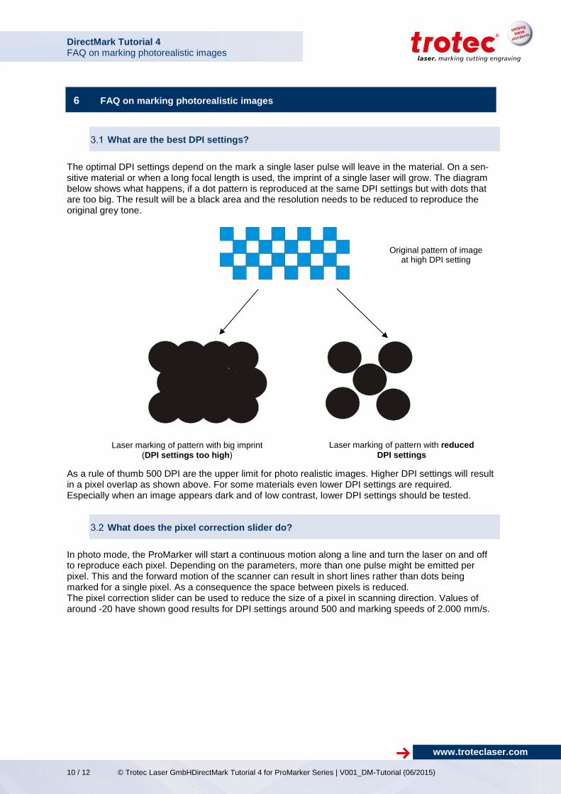
6 FAQ on marking photorealistic images
What are the best DPI settings?
The optimal DPI settings depend on the mark a single laser pulse will leave in the material. On a sen-sitive material or when a long focal length is used, the imprint of a single laser will grow. The diagram below shows what happens, if a dot pattern is reproduced at the same DPI settings but with dots that are too big. The result will be a black area and the resolution needs to be reduced to reproduce the original grey tone.
As a rule of thumb 500 DPI are the upper limit for photo realistic images. Higher DPI settings will result in a pixel overlap as shown above. For some materials even lower DPI settings are required. Especially when an image appears dark and of low contrast, lower DPI settings should be tested.
What does the pixel correction slider do?
In photo mode, the ProMarker will start a continuous motion along a line and turn the laser on and off to reproduce each pixel. Depending on the parameters, more than one pulse might be emitted per pixel. This and the forward motion of the scanner can result in short lines rather than dots being marked for a single pixel. As a consequence the space between pixels is reduced. The pixel correction slider can be used to reduce the size of a pixel in scanning direction. Values of around -20 have shown good results for DPI settings around 500 and marking speeds of 2.000 mm/s.
Original pattern of image at high DPI setting
Laser marking of pattern with big imprint
(DPI settings too high)
Laser marking of pattern with reduced
DPI settings

DirectMark Tutorial 4 FAQ on marking photorealistic images
DirectMark Tutorial 4 for ProMarker Series | V001_DM-Tutorial (06/2015) © Trotec Laser GmbH 11 / 12
www.troteclaser.com
Finding the right parameters of speed and frequency
When marking photo realistic images, a relationship between the marking speed and the frequency (repetition rate) of the laser should be observed. As the scanner moves the laser beam across the material, the laser is turned on and off at a rate defined by the density of pixels and the scanning speed of the laser. At the same time the laser itself emits pulses at a rate defined by the repetition rate (frequency) set in the marking parameters. If the combination of marking speed and frequency is chosen badly, the pixels will be marked with an overlying pattern. The figure schematically shows the pixel spacing for a 300 DPI bitmap compared to the distance be-tween two laser pulses at different laser settings. For the laser parameters (b) the spacing of two laser pulses is bigger then the pixel distance of the original image (a).
In multiple test the combination of 50kHz and 2.000 mm/s have shown the best results.
What is dithering?
Dithering, halftoning or rastering are terms used to describe a process whereby grey tone images are reproduced using black and white pixels of varying density only.1
1 Dithering, halftoning or rastering can also use a raster of multiple colors not only black and white
Without pixel reduction
With pixel reduction
a) Bitmap at 300 DPI
b) “Line” of pulses at 3.000M/s and 20kHz (Not enough pulses to reproduce pattern)
c) “Line” of pulses at 3.000M/s an 40kHz

DirectMark Tutorial 4 FAQ on marking photorealistic images
Trotec Laser GmbH Trotec Laser GmbH Linzer Straße 156 Freilingerstraße 99 A – 4600 Wels A – 4614 Marchtrenk AUSTRIA AUSTRIA Technische Änderungen vorbehalten
12 / 12 © Trotec Laser GmbHDirectMark Tutorial 4 for ProMarker Series | V001_DM-Tutorial (06/2015)
www.troteclaser.com
When marking photo realistic images, in a first step, a color image is first turned into a grey scale image. In a grey scale image, pixels vary in “darkness” e.g. 256 tones of grey as shown on the far right of the image below.
Source: Wikipedia
By its nature, a fibre laser is not able to change the power in-between two adjacent pixels. As a result, all pixels are marked using the same laser settings and will therefore appear in the same darkness. The grey tones contained in the original image therefore need to be reproduced using black and white pixels only. The gray scale image needs to be turned into an image containing only black and white pixels. This is called dithering or rastering. Instead of having pixels of different grey tones, the different shades of grey are represented by varying densities of pixels. There are different algorithms available to produce the pixel patterns (e.g. Floyd-Steinberger Jarvis, …). Depending on the algorithm used and the picture being rastered, the dithering patterns can introduce overlying patterns that may appear in the image requiring a different algorithm.
Subject to technical changes.