Embed Size (px)
Citation preview

Tutorial 13: Facade wizard
Copyright © 1995-2015 Esri. All rights reserved.
Table of ContentsTutorial 13: Facade wizard . . . . . . . . . . . . . . . . . . . . . . . . . . . . . . . . . . . . . . . . . . 3
Tutorial 13: Facade wizard
Copyright © 1995-2015 Esri. All rights reserved. 2
Tutorial 13: Facade wizardDownload items
• Tutorial data
• Tutorial PDF
Part 1: Intro and Basic Example
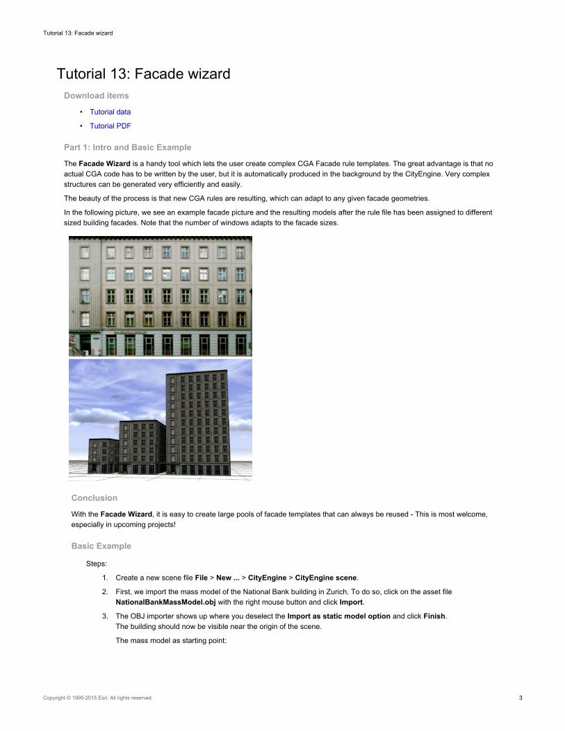
The Facade Wizard is a handy tool which lets the user create complex CGA Facade rule templates. The great advantage is that noactual CGA code has to be written by the user, but it is automatically produced in the background by the CityEngine. Very complexstructures can be generated very efficiently and easily.
The beauty of the process is that new CGA rules are resulting, which can adapt to any given facade geometries.
In the following picture, we see an example facade picture and the resulting models after the rule file has been assigned to differentsized building facades. Note that the number of windows adapts to the facade sizes.
Conclusion
With the Facade Wizard, it is easy to create large pools of facade templates that can always be reused - This is most welcome,especially in upcoming projects!
Basic Example
Steps:
1. Create a new scene file File > New ... > CityEngine > CityEngine scene.
2. First, we import the mass model of the National Bank building in Zurich. To do so, click on the asset fileNationalBankMassModel.obj with the right mouse button and click Import.
3. The OBJ importer shows up where you deselect the Import as static model option and click Finish.The building should now be visible near the origin of the scene.
The mass model as starting point:
Tutorial 13: Facade wizard
Copyright © 1995-2015 Esri. All rights reserved. 3
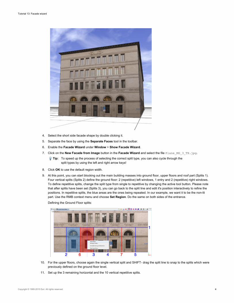
4. Select the short side facade shape by double clicking it.
5. Separate the face by using the Separate Faces tool in the toolbar.
6. Enable the Facade Wizard under Window > Show Facade Wizard.
7. Click on the New Facade from Image button in the Facade Wizard and select the file Plane_MG_3_TX.jpg.
Tip: To speed up the process of selecting the correct split type, you can also cycle through thesplit types by using the left and right arrow keys!
8. Click OK to use the default region width.
9. At this point, you can start blocking out the main building masses into ground floor, upper floors and roof part (Splits 1).Four vertical splits (Splits 2) define the ground floor: 2 (repetitive) left windows, 1 entry and 2 (repetitive) right windows.To define repetitive splits, change the split type from single to repetitive by changing the active tool button. Please notethat after splits have been set (Splits 3), you can go back to the split line and edit it's position interactively to refine thepositions. In repetitive splits, the blue areas are the ones being repeated. In our example, we want it to be the non-litpart. Use the RMB context menu and choose Set Region. Do the same on both sides of the entrance.
Defining the Ground Floor splits:
10. For the upper floors, choose again the single vertical split and SHIFT- drag the split line to snap to the splits which werepreviously defined on the ground floor level.
11. Set up the 3 remaining horizontal and the 10 vertical repetitive splits.
Tutorial 13: Facade wizard
Copyright © 1995-2015 Esri. All rights reserved. 4
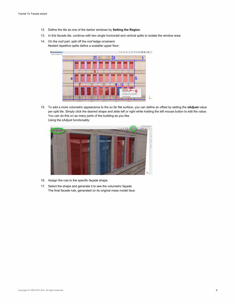
12. Define the tile as one of the darker windows by Setting the Region.
13. In this facade tile, continue with two single horizontal and vertical splits to isolate the window area.
14. On the roof part, split off the roof ledge ornament.Nested repetitive splits define a scalable upper floor:
15. To add a more volumetric appearance to the so far flat surface, you can define an offset by setting the zAdjust valueper split tile. Simply click the desired shape and slide left or right while holding the left mouse button to edit the value.You can do this on as many parts of the building as you like.Using the zAdjust functionality:
16. Assign the rule to the specific façade shape.
17. Select the shape and generate it to see the volumetric façade.The final facade rule, generated on its original mass model face:
Tutorial 13: Facade wizard
Copyright © 1995-2015 Esri. All rights reserved. 5
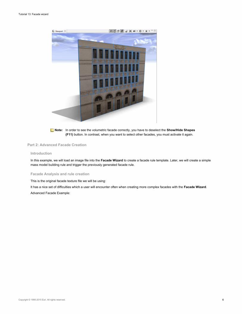
Note: In order to see the volumetric facade correctly, you have to deselect the Show/Hide Shapes(F11) button. In contrast, when you want to select other facades, you must activate it again.
Part 2: Advanced Facade Creation
Introduction
In this example, we will load an image file into the Facade Wizard to create a facade rule template. Later, we will create a simplemass model building rule and trigger the previously generated facade rule.
Facade Analysis and rule creation
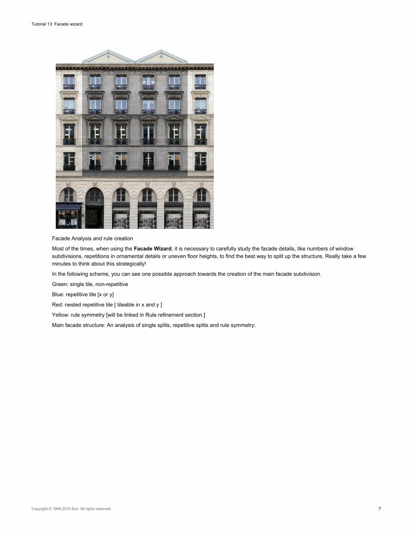
This is the original facade texture file we will be using:
It has a nice set of difficulties which a user will encounter often when creating more complex facades with the Facade Wizard.
Advanced Facade Example:
Tutorial 13: Facade wizard
Copyright © 1995-2015 Esri. All rights reserved. 6
Facade Analysis and rule creation
Most of the times, when using the Facade Wizard, it is necessary to carefully study the facade details, like numbers of windowsubdivisions, repetitions in ornamental details or uneven floor heights, to find the best way to split up the structure. Really take a fewminutes to think about this strategically!
In the following scheme, you can see one possible approach towards the creation of the main facade subdivision.
Green: single tile, non-repetitive
Blue: repetitive tile [x or y]
Red: nested repetitive tile [ tileable in x and y ]
Yellow: rule symmetry [will be linked in Rule refinement section.]
Main facade structure: An analysis of single splits, repetitive splits and rule symmetry:
Tutorial 13: Facade wizard
Copyright © 1995-2015 Esri. All rights reserved. 7
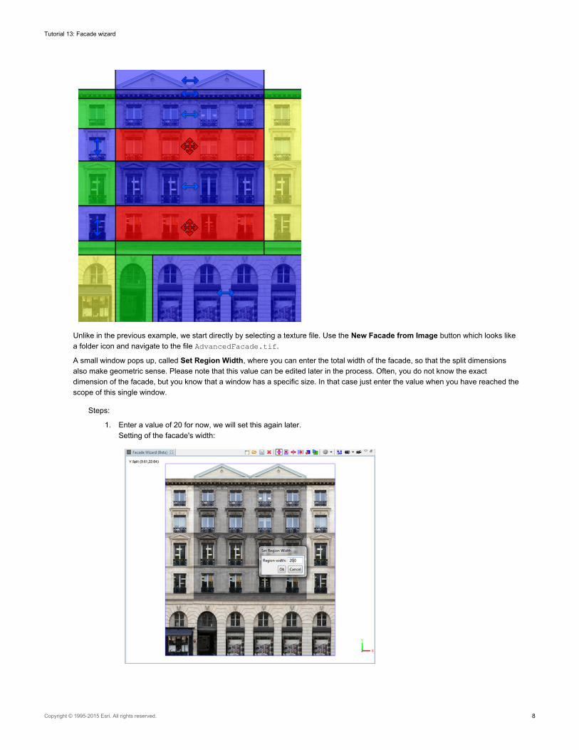
Unlike in the previous example, we start directly by selecting a texture file. Use the New Facade from Image button which looks likea folder icon and navigate to the file AdvancedFacade.tif.
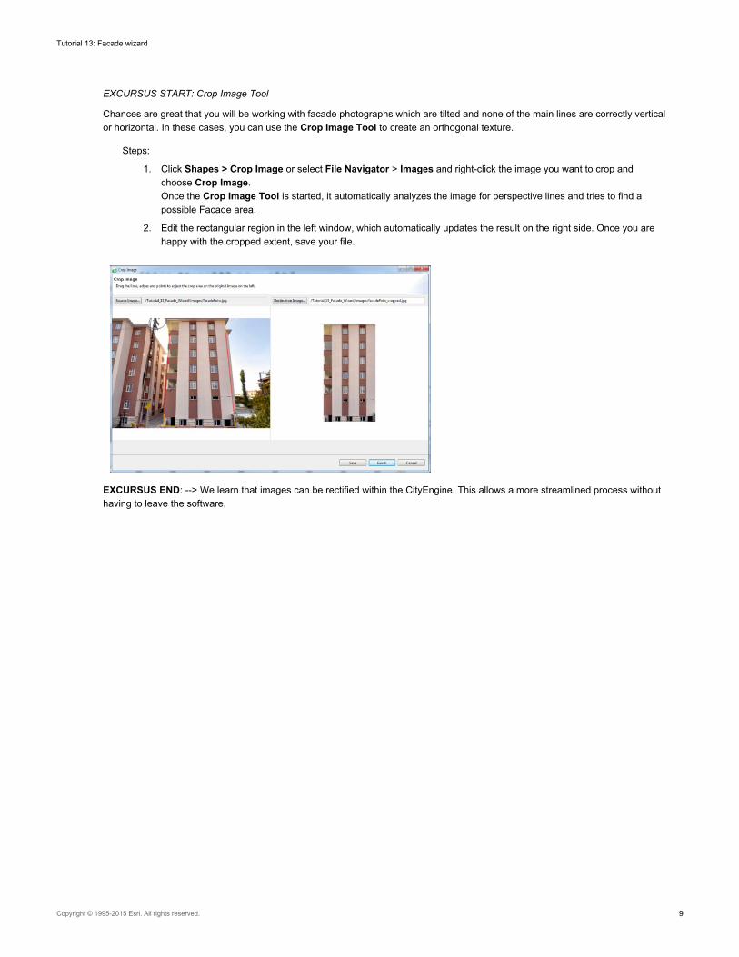
A small window pops up, called Set Region Width, where you can enter the total width of the facade, so that the split dimensionsalso make geometric sense. Please note that this value can be edited later in the process. Often, you do not know the exactdimension of the facade, but you know that a window has a specific size. In that case just enter the value when you have reached thescope of this single window.
Steps:
1. Enter a value of 20 for now, we will set this again later.Setting of the facade's width:
Tutorial 13: Facade wizard
Copyright © 1995-2015 Esri. All rights reserved. 8
EXCURSUS START: Crop Image Tool
Chances are great that you will be working with facade photographs which are tilted and none of the main lines are correctly verticalor horizontal. In these cases, you can use the Crop Image Tool to create an orthogonal texture.
Steps:
1. Click Shapes > Crop Image or select File Navigator > Images and right-click the image you want to crop andchoose Crop Image.Once the Crop Image Tool is started, it automatically analyzes the image for perspective lines and tries to find apossible Facade area.
2. Edit the rectangular region in the left window, which automatically updates the result on the right side. Once you arehappy with the cropped extent, save your file.
EXCURSUS END: --> We learn that images can be rectified within the CityEngine. This allows a more streamlined process withouthaving to leave the software.
Tutorial 13: Facade wizard
Copyright © 1995-2015 Esri. All rights reserved. 9
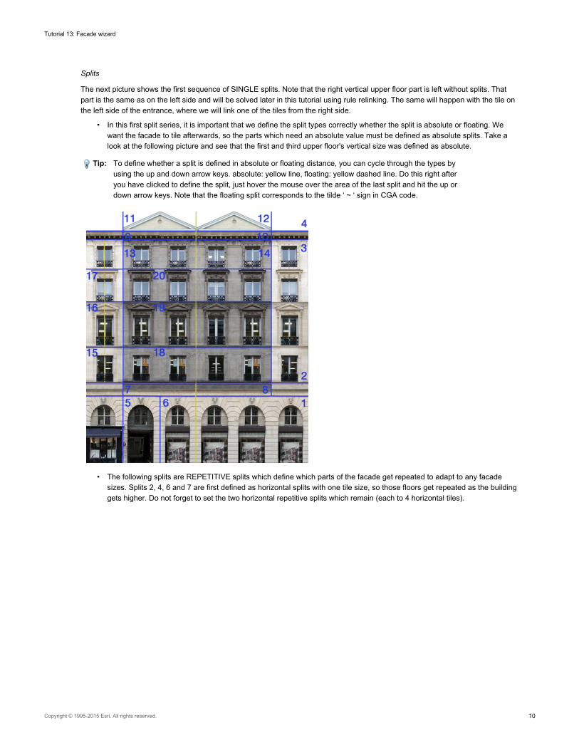
Splits
The next picture shows the first sequence of SINGLE splits. Note that the right vertical upper floor part is left without splits. Thatpart is the same as on the left side and will be solved later in this tutorial using rule relinking. The same will happen with the tile onthe left side of the entrance, where we will link one of the tiles from the right side.
• In this first split series, it is important that we define the split types correctly whether the split is absolute or floating. Wewant the facade to tile afterwards, so the parts which need an absolute value must be defined as absolute splits. Take alook at the following picture and see that the first and third upper floor's vertical size was defined as absolute.
Tip: To define whether a split is defined in absolute or floating distance, you can cycle through the types byusing the up and down arrow keys. absolute: yellow line, floating: yellow dashed line. Do this right afteryou have clicked to define the split, just hover the mouse over the area of the last split and hit the up ordown arrow keys. Note that the floating split corresponds to the tilde ‘ ~ ‘ sign in CGA code.
• The following splits are REPETITIVE splits which define which parts of the facade get repeated to adapt to any facadesizes. Splits 2, 4, 6 and 7 are first defined as horizontal splits with one tile size, so those floors get repeated as the buildinggets higher. Do not forget to set the two horizontal repetitive splits which remain (each to 4 horizontal tiles).
Tutorial 13: Facade wizard
Copyright © 1995-2015 Esri. All rights reserved. 10
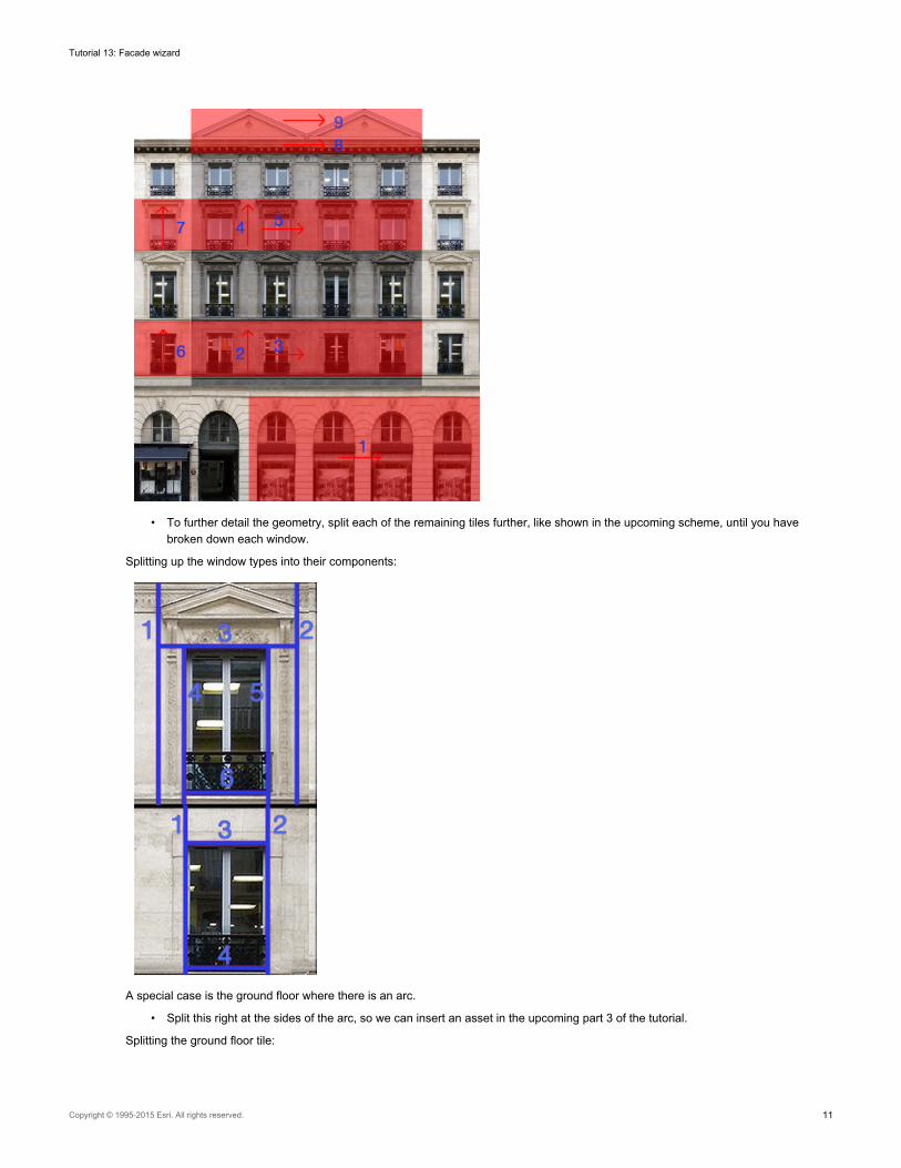
• To further detail the geometry, split each of the remaining tiles further, like shown in the upcoming scheme, until you havebroken down each window.
Splitting up the window types into their components:
A special case is the ground floor where there is an arc.
• Split this right at the sides of the arc, so we can insert an asset in the upcoming part 3 of the tutorial.
Splitting the ground floor tile:
Tutorial 13: Facade wizard
Copyright © 1995-2015 Esri. All rights reserved. 11
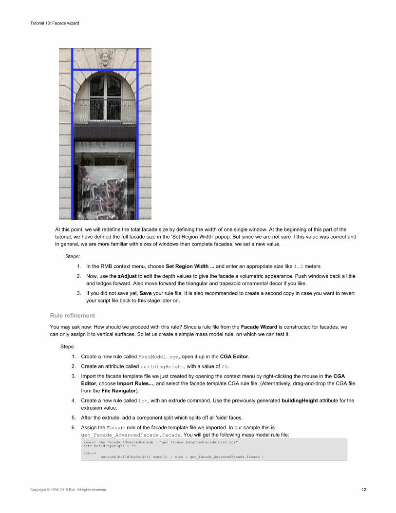
At this point, we will redefine the total facade size by defining the width of one single window. At the beginning of this part of thetutorial, we have defined the full facade size in the ‘Set Region Width’ popup. But since we are not sure if this value was correct andin general, we are more familiar with sizes of windows than complete facades, we set a new value.
Steps:
1. In the RMB context menu, choose Set Region Width ... and enter an appropriate size like 1.2 meters
2. Now, use the zAdjust to edit the depth values to give the facade a volumetric appearance. Push windows back a littleand ledges forward. Also move forward the triangular and trapezoid ornamental decor if you like.
3. If you did not save yet, Save your rule file. It is also recommended to create a second copy in case you want to revertyour script file back to this stage later on.
Rule refinement
You may ask now: How should we proceed with this rule? Since a rule file from the Facade Wizard is constructed for facades, wecan only assign it to vertical surfaces. So let us create a simple mass model rule, on which we can test it.
Steps:
1. Create a new rule called MassModel.cga, open it up in the CGA Editor.
2. Create an attribute called buildingHeight, with a value of 25.
3. Import the facade template file we just created by opening the context menu by right-clicking the mouse in the CGAEditor, choose Import Rules..., and select the facade template CGA rule file. (Alternatively, drag-and-drop the CGA filefrom the File Navigator).
4. Create a new rule called Lot, with an extrude command. Use the previously generated buildingHeight attribute for theextrusion value.
5. After the extrude, add a component split which splits off all 'side' faces.
6. Assign the Facade rule of the facade template file we imported. In our sample this isgen_Facade_AdvancedFacade.Facade. You will get the following mass model rule file:import gen_Facade_AdvancedFacade : "gen_Facade_AdvancedFacade_dist.cga"attr buildingHeight = 25
Lot-->extrude(buildingHeight) comp(f) { side : gen_Facade_AdvancedFacade.Facade }
Tutorial 13: Facade wizard
Copyright © 1995-2015 Esri. All rights reserved. 12
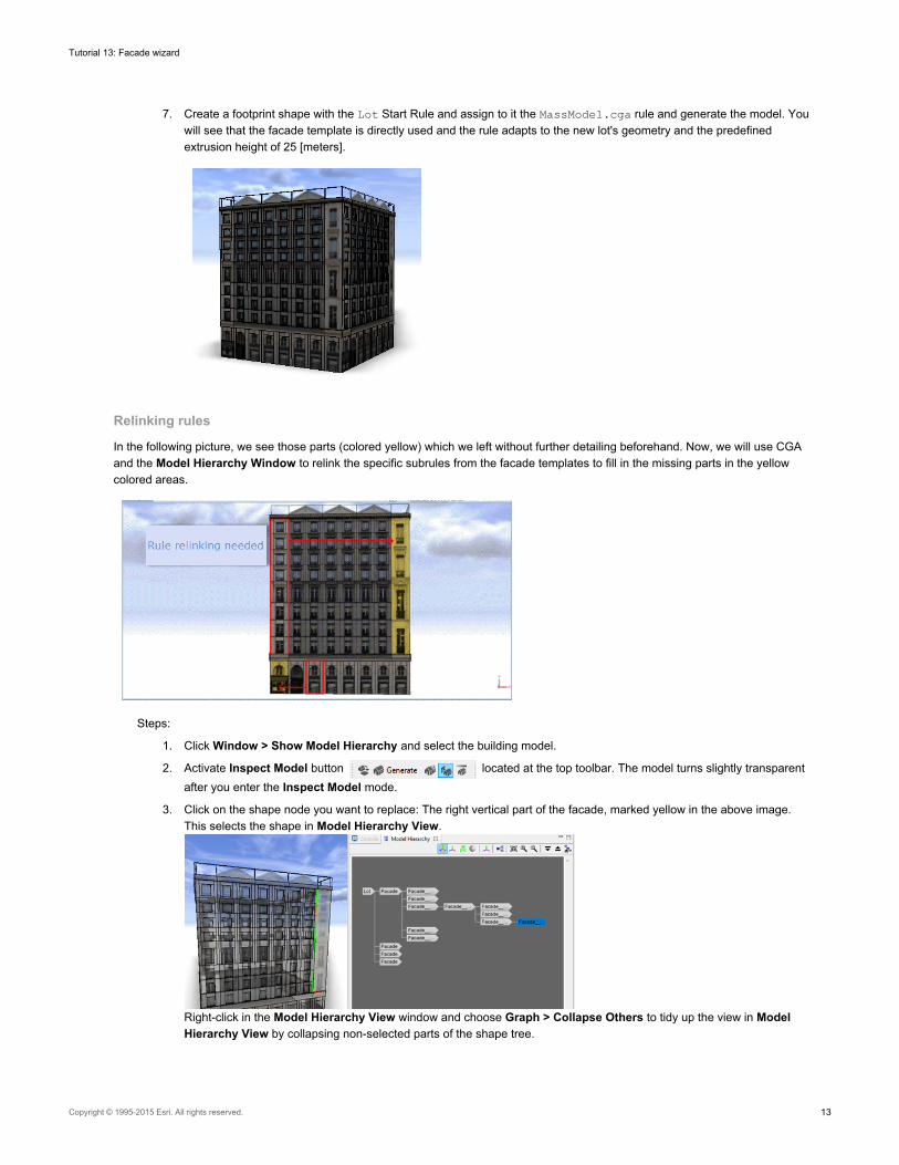
7. Create a footprint shape with the Lot Start Rule and assign to it the MassModel.cga rule and generate the model. Youwill see that the facade template is directly used and the rule adapts to the new lot's geometry and the predefinedextrusion height of 25 [meters].
Relinking rules
In the following picture, we see those parts (colored yellow) which we left without further detailing beforehand. Now, we will use CGAand the Model Hierarchy Window to relink the specific subrules from the facade templates to fill in the missing parts in the yellowcolored areas.
Steps:
1. Click Window > Show Model Hierarchy and select the building model.
2. Activate Inspect Model button located at the top toolbar. The model turns slightly transparentafter you enter the Inspect Model mode.
3. Click on the shape node you want to replace: The right vertical part of the facade, marked yellow in the above image.This selects the shape in Model Hierarchy View.
Right-click in the Model Hierarchy View window and choose Graph > Collapse Others to tidy up the view in ModelHierarchy View by collapsing non-selected parts of the shape tree.
Tutorial 13: Facade wizard
Copyright © 1995-2015 Esri. All rights reserved. 13
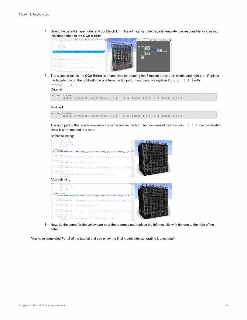
4. Select the parent shape node, and double click it. This will highlight the Facade template rule responsible for creatingthis shape node in the CGA Editor.
5. The selected rule in the CGA Editor is responsible for creating the 3 facade parts: Left, middle and right part. Replacethe facade rule on the right with the one from the left part. In our case, we replace Facade__1_3_3 withFacade__1_3_1.Original:
Facade__1_3 -->split(x, noAdjust) { 2.68: Facade__1_3_1 | ~10.62: Facade__1_3_2 | 2.66: Facade__1_3_3 }
Modified:
Facade__1_3 -->split(x, noAdjust) { 2.68: Facade__1_3_1 | ~10.62: Facade__1_3_2 | 2.66: Facade__1_3_1 }
The right part of the facade now uses the same rule as the left. The now unused rule Facade__1_3_3 can be deletedsince it is not needed any more.
Before relinking:
After relinking:
6. Now, do the same for the yellow part near the entrance and replace the left most tile with the one to the right of theentry.
You have completed Part 2 of the tutorial and can enjoy the final model after generating it once again:
Tutorial 13: Facade wizard
Copyright © 1995-2015 Esri. All rights reserved. 14
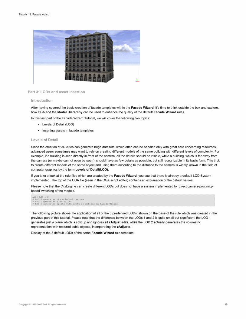
Part 3: LODs and asset insertion
Introduction
After having covered the basic creation of facade templates within the Facade Wizard, it's time to think outside the box and explore,how CGA and the Model Hierarchy can be used to enhance the quality of the default Facade Wizard rules.
In this last part of the Facade Wizard Tutorial, we will cover the following two topics:
• Levels of Detail (LOD)
• Inserting assets in facade templates
Levels of Detail
Since the creation of 3D cities can generate huge datasets, which often can be handled only with great care concerning resources,advanced users sometimes may want to rely on creating different models of the same building with different levels of complexity. Forexample, if a building is seen directly in front of the camera, all the details should be visible, while a building, which is far away fromthe camera (or maybe cannot even be seen), should have as few details as possible, but still recognizable in its basic form. This trickto create different models of the same object and using them according to the distance to the camera is widely known in the field ofcomputer graphics by the term Levels of Detail(LOD).
If you take a look at the rule files which are created by the Facade Wizard, you see that there is already a default LOD Systemimplemented. The top of the CGA file (seen in the CGA script editor) contains an explanation of the default values.
Please note that the CityEngine can create different LODs but does not have a system implemented for direct camera-proximity-based switching of the models.
attr LOD = 2# LOD 0 generates the original texture# LOD 1 generates flat splits# LOD 2 generates splits with depth as defined in Facade Wizard
The following picture shows the application of all of the 3 predefined LODs, shown on the base of the rule which was created in theprevious part of this tutorial. Please note that the difference between the LODs 1 and 2 is quite small but significant: the LOD 1generates just a plane which is split up and ignores all zAdjust edits, while the LOD 2 actually generates the volumetricrepresentation with textured cubic objects, incorporating the zAdjusts.
Display of the 3 default LODs of the same Facade Wizard rule template:
Tutorial 13: Facade wizard
Copyright © 1995-2015 Esri. All rights reserved. 15
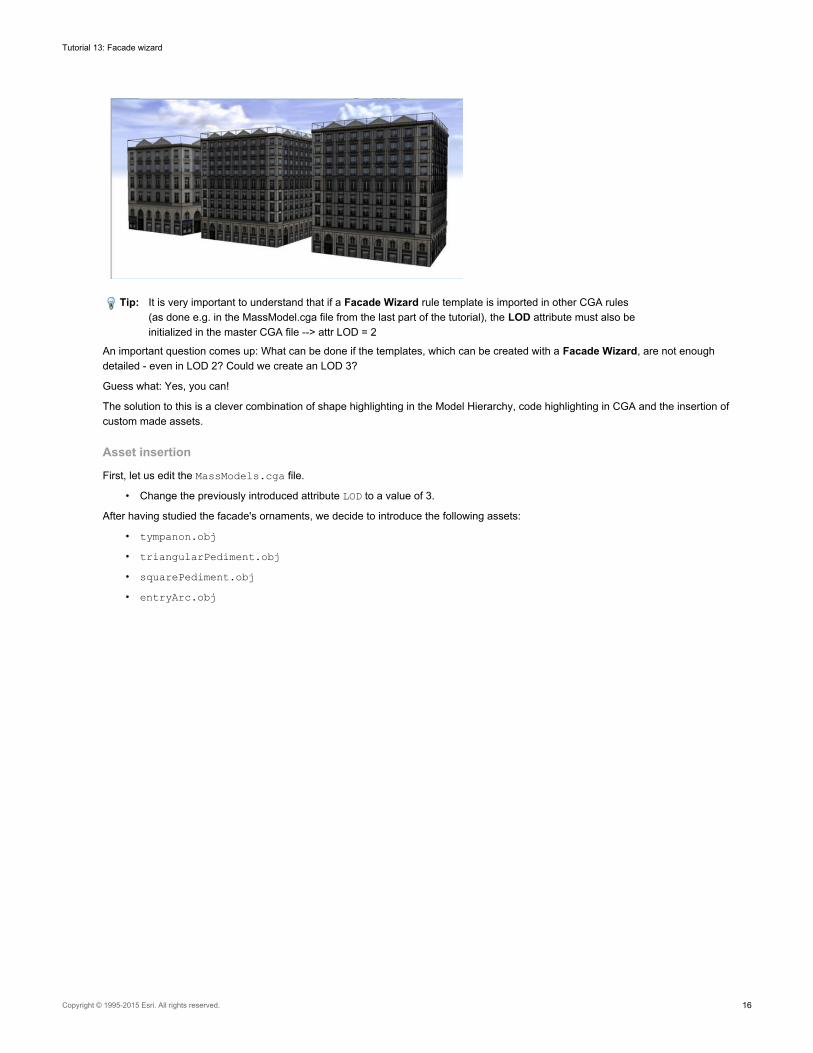
Tip: It is very important to understand that if a Facade Wizard rule template is imported in other CGA rules(as done e.g. in the MassModel.cga file from the last part of the tutorial), the LOD attribute must also beinitialized in the master CGA file --> attr LOD = 2
An important question comes up: What can be done if the templates, which can be created with a Facade Wizard, are not enoughdetailed - even in LOD 2? Could we create an LOD 3?
Guess what: Yes, you can!
The solution to this is a clever combination of shape highlighting in the Model Hierarchy, code highlighting in CGA and the insertion ofcustom made assets.
Asset insertion
First, let us edit the MassModels.cga file.
• Change the previously introduced attribute LOD to a value of 3.
After having studied the facade's ornaments, we decide to introduce the following assets:
• tympanon.obj
• triangularPediment.obj
• squarePediment.obj
• entryArc.obj
Tutorial 13: Facade wizard
Copyright © 1995-2015 Esri. All rights reserved. 16
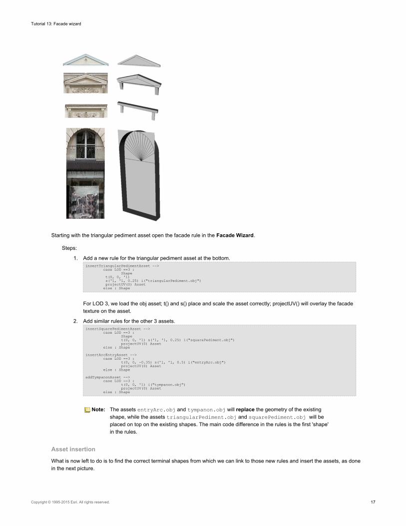
Starting with the triangular pediment asset open the facade rule in the Facade Wizard.
Steps:
1. Add a new rule for the triangular pediment asset at the bottom.insertTriangularPedimentAsset -->
case LOD ==3 :Shape
t(0, 0, '1)s('1, '1, 0.25) i("triangularPediment.obj")projectUV(0) Asset
else : Shape
For LOD 3, we load the obj asset; t() and s() place and scale the asset correctly; projectUV() will overlay the facadetexture on the asset.
2. Add similar rules for the other 3 assets.insertSquarePedimentAsset -->
case LOD ==3 :Shapet(0, 0, '1) s('1, '1, 0.25) i("squarePediment.obj")projectUV(0) Asset
else : Shape
insertArcEntryAsset -->case LOD ==3 :
t(0, 0, -0.35) s('1, '1, 0.5) i("entryArc.obj")projectUV(0) Asset
else : Shape
addTympanonAsset -->case LOD ==3 :
t(0, 0, '1) i("tympanon.obj")projectUV(0) Asset
else : Shape
Note: The assets entryArc.obj and tympanon.obj will replace the geometry of the existingshape, while the assets triangularPediment.obj and squarePediment.obj will beplaced on top on the existing shapes. The main code difference in the rules is the first 'shape'in the rules.
Asset insertion
What is now left to do is to find the correct terminal shapes from which we can link to those new rules and insert the assets, as donein the next picture.
Tutorial 13: Facade wizard
Copyright © 1995-2015 Esri. All rights reserved. 17
Steps:
1. Select the building and go into Inspect Model mode.
2. Select the shape where the asset is to be inserted.
3. In Model Hierarchy View, double-click the selected shape. This will highlight the facade template rule responsible forcreating this shape node in the CGA editor .
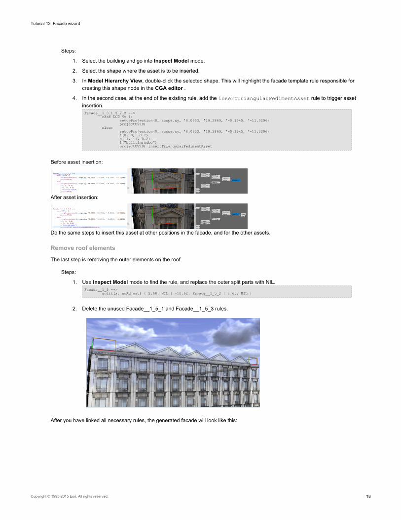
4. In the second case, at the end of the existing rule, add the insertTriangularPedimentAsset rule to trigger assetinsertion.Facade__1_3_1_2_2_2 -->
case LOD <= 1:setupProjection(0, scope.xy, '8.0953, '19.2869, '-0.1945, '-11.3296)projectUV(0)
else:setupProjection(0, scope.xy, '8.0953, '19.2869, '-0.1945, '-11.3296)t(0, 0, -0.2)s('1, '1, 0.2)i("builtin:cube")projectUV(0) insertTriangularPedimentAsset
Before asset insertion:
After asset insertion:
Do the same steps to insert this asset at other positions in the facade, and for the other assets.
Remove roof elements
The last step is removing the outer elements on the roof.
Steps:
1. Use Inspect Model mode to find the rule, and replace the outer split parts with NIL.Facade__1_5 -->
split(x, noAdjust) { 2.68: NIL | ~10.62: Facade__1_5_2 | 2.66: NIL }
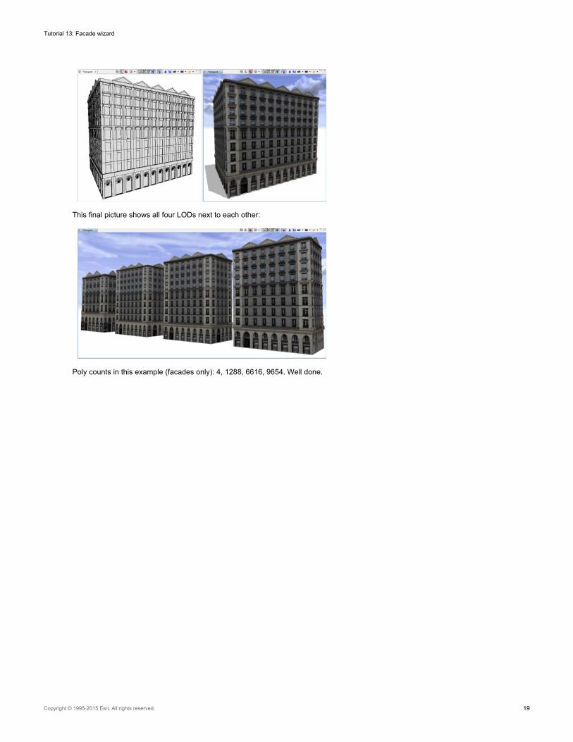
2. Delete the unused Facade__1_5_1 and Facade__1_5_3 rules.
After you have linked all necessary rules, the generated facade will look like this:
Tutorial 13: Facade wizard
Copyright © 1995-2015 Esri. All rights reserved. 18
This final picture shows all four LODs next to each other:
Poly counts in this example (facades only): 4, 1288, 6616, 9654. Well done.
Tutorial 13: Facade wizard
Copyright © 1995-2015 Esri. All rights reserved. 19


![[Tutorial] SilverDev Wizard - english](https://img.pdfslide.us/doc/110x75/5590d4f21a28ab65148b4717/tutorial-silverdev-wizard-english.jpg)