Embed Size (px)
Citation preview
DINO Peer Review 10 December 2003
ScienceJessica PipisDohy Faied
Paul KolesnikoffBrian Taylor
Miranda MeslohDavid Goluskin
DINO Peer Review April 18, 2023
Introduction
• The purpose of the science subsystem is to take stereoscopic images of clouds in order to create a topographic map of cloud heights.
• There will be two camera’s mounted at specific angles on the satellite.
• The gathered images will be sent to the flight computer where an algorithm will find matching points. Using these points the images will be overlaid creating a topographic map which will be sent back to CU.
• Also included is a description of an algorithm and test plan.
DINO Peer Review April 18, 2023
Requirements
• The Science subsystem shall be designed to meet all of DINO’s science objectives. It will implement a stereoscopic imaging technique in order to measure cloud heights.
• Clouds imaged in the visible spectrum
• Field of view of 40-55 degrees is needed for cameras.
• Cameras will have a resolution of better than 640x480.
• Shutter speed of 1/64th of a second or faster
• Ample amount of time shall be allotted for the software system to finish processing an image before another image is required
• Each of the multiple images used to produce a topographic map of the cloud must contain the same features
DINO Peer Review April 18, 2023
Requirements
• Mass- 0.56 kg on the main satellite • Power- less than 11 Watts on the main satellite • The Science subsystem will operate on 5V and/or
12V lines• All Science subsystem components shall comply
with NASA’s safety requirements – There shall be no pressurized vessels in the science
subsystem, including the lens of each camera– All components will comply with NASA’s outgassing
specifications– Any glass components shall comply with NASA’s regulations– All components shall either be contained or meet NASA’s
requirements to be a low-released mass part
DINO Peer Review April 18, 2023
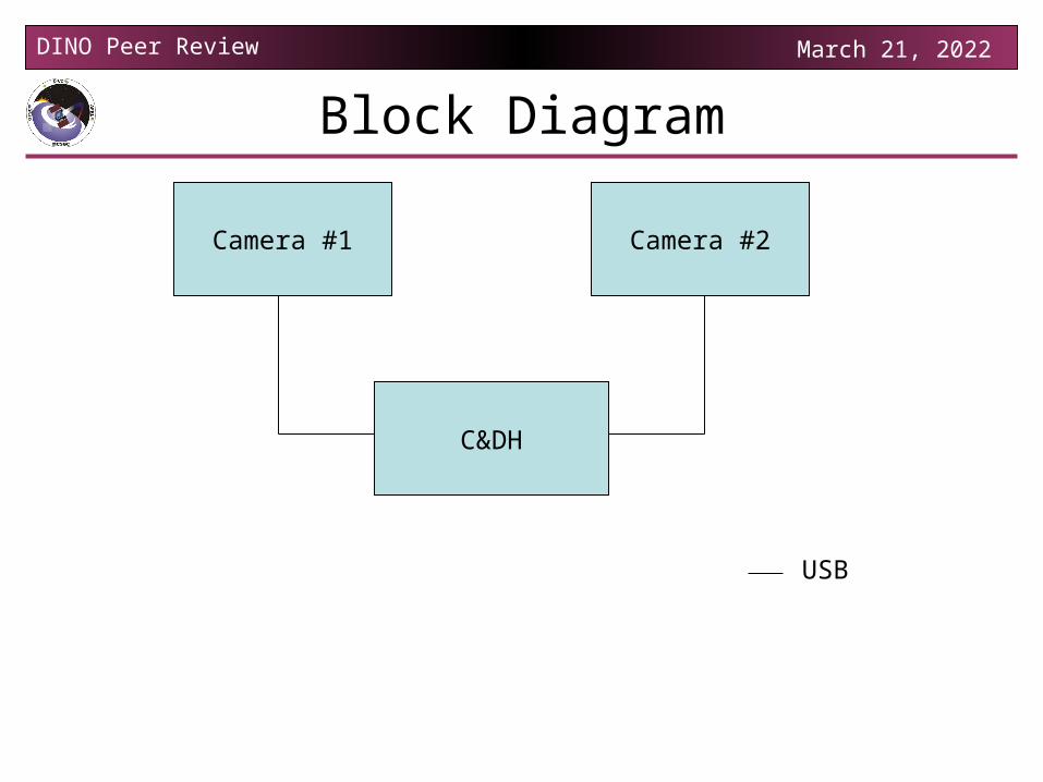
Block Diagram
Camera #1 Camera #2
C&DH
USB
DINO Peer Review April 18, 2023
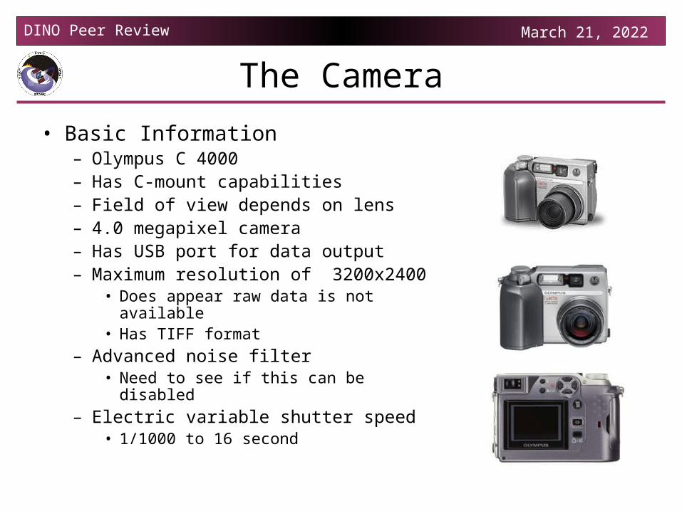
The Camera
• Basic Information– Olympus C 4000– Has C-mount capabilities– Field of view depends on lens– 4.0 megapixel camera– Has USB port for data output– Maximum resolution of 3200x2400
• Does appear raw data is not available• Has TIFF format
– Advanced noise filter• Need to see if this can be disabled
– Electric variable shutter speed• 1/1000 to 16 second
DINO Peer Review April 18, 2023
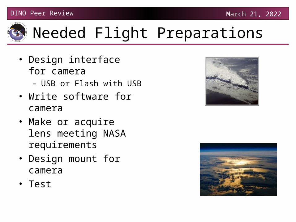
Needed Flight Preparations
• Design interface for camera– USB or Flash with USB
• Write software for camera • Make or acquire lens
meeting NASA requirements
• Design mount for camera• Test
DINO Peer Review April 18, 2023
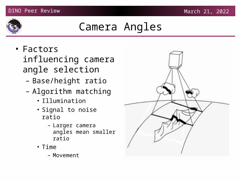
Camera Angles
• Factors influencing camera angle selection– Base/height ratio– Algorithm matching
• Illumination • Signal to noise ratio
– Larger camera angles mean smaller ratio
• Time– Movement
DINO Peer Review April 18, 2023
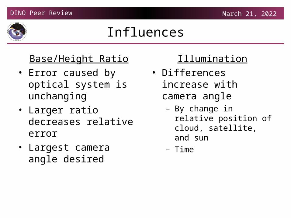
Influences
Base/Height Ratio• Error caused by optical
system is unchanging• Larger ratio decreases
relative error• Largest camera angle
desired
Illumination• Differences increase with
camera angle– By change in relative
position of cloud, satellite, and sun
– Time
DINO Peer Review April 18, 2023
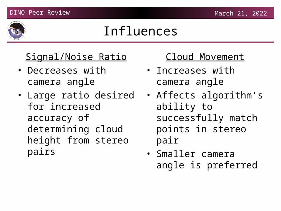
Influences
Signal/Noise Ratio• Decreases with camera
angle• Large ratio desired for
increased accuracy of determining cloud height from stereo pairs
Cloud Movement• Increases with camera
angle• Affects algorithm’s ability
to successfully match points in stereo pair
• Smaller camera angle is preferred
DINO Peer Review April 18, 2023
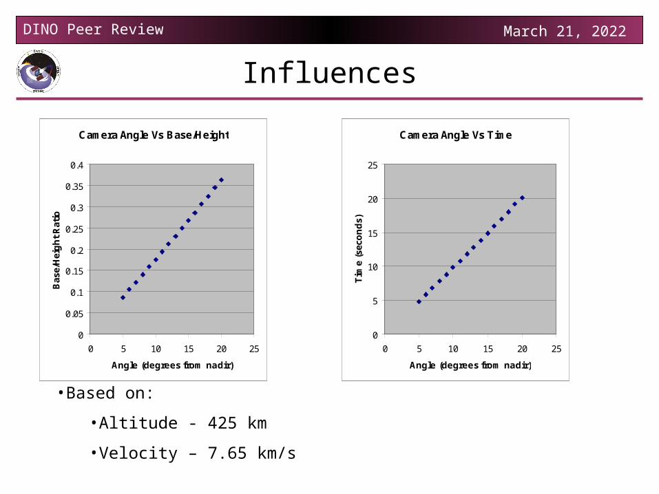
Influences
•Based on:
•Altitude - 425 km
•Velocity – 7.65 km/s
Camera Angle Vs Base/Height
0
0.05
0.1
0.15
0.2
0.25
0.3
0.35
0.4
0 5 10 15 20 25
Angle (degrees from nadir)
Bas
e/H
eig
ht
Rat
io
Camera Angle Vs Time
0
5
10
15
20
25
0 5 10 15 20 25
Angle (degrees from nadir)T
ime
(sec
on
ds)
DINO Peer Review April 18, 2023
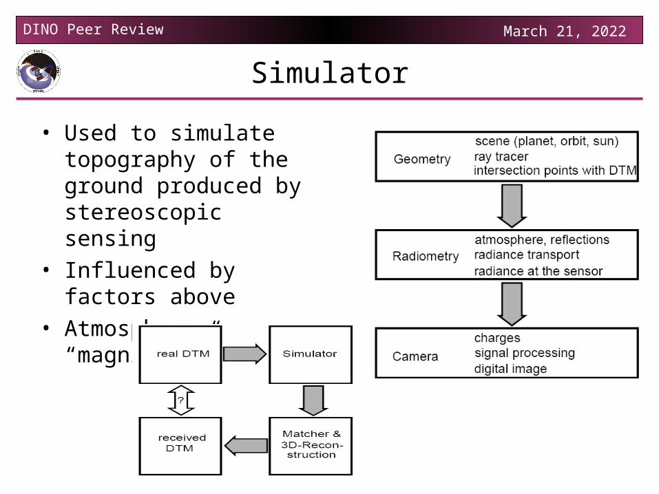
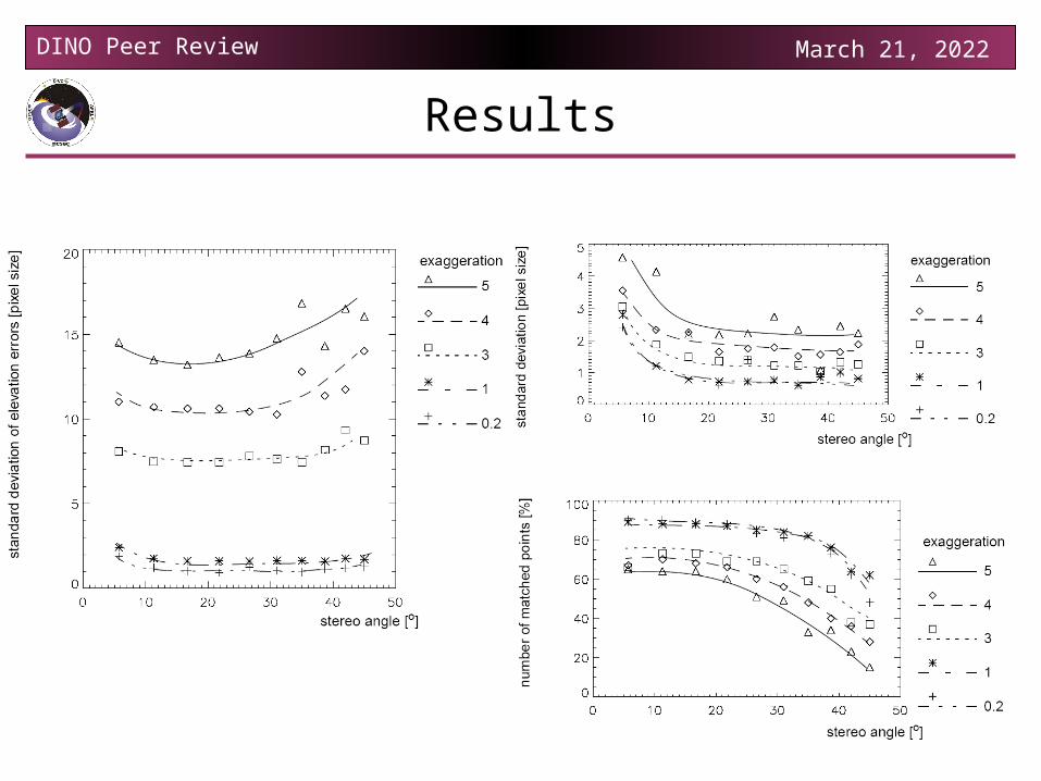
Simulator
• Used to simulate topography of the ground produced by stereoscopic sensing
• Influenced by factors above
• Atmosphere “magnifies” results
DINO Peer Review April 18, 2023
Results
DINO Peer Review April 18, 2023
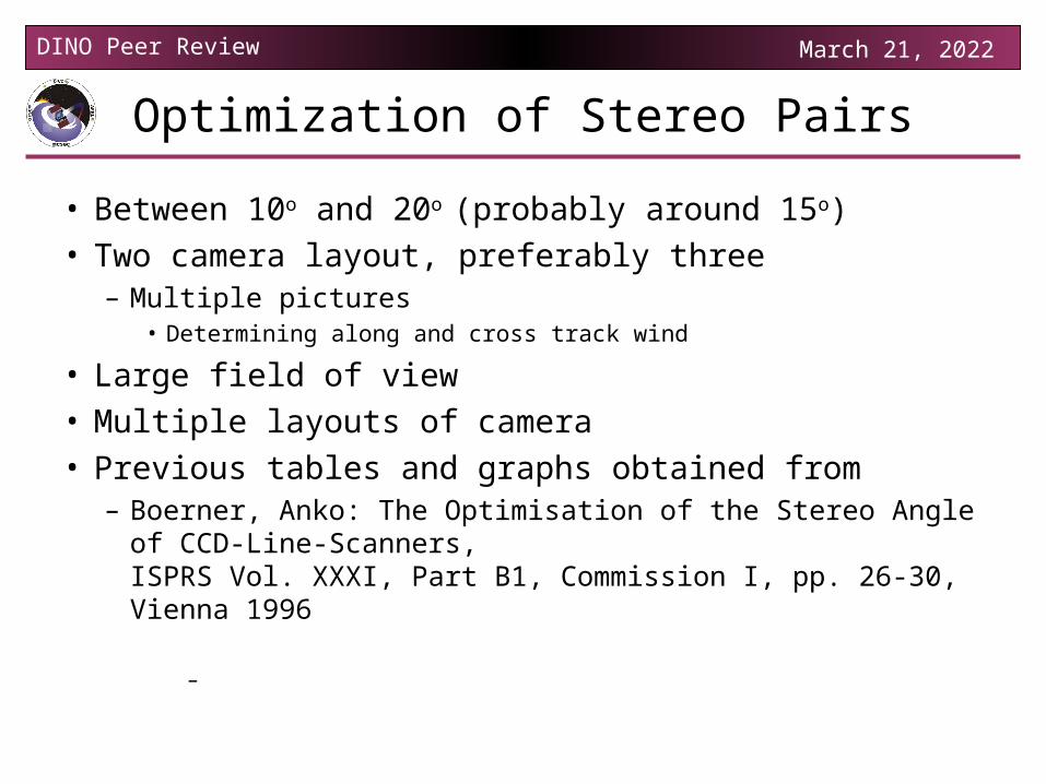
Optimization of Stereo Pairs
• Between 10o and 20o (probably around 15o)
• Two camera layout, preferably three– Multiple pictures
• Determining along and cross track wind
• Large field of view
• Multiple layouts of camera
• Previous tables and graphs obtained from – Boerner, Anko: The Optimisation of the Stereo Angle of CCD-
Line-Scanners,ISPRS Vol. XXXI, Part B1, Commission I, pp. 26-30, Vienna 1996
–
DINO Peer Review April 18, 2023
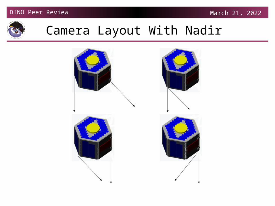
Camera Layout With Nadir
DINO Peer Review April 18, 2023
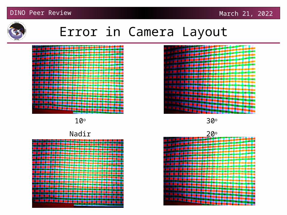
Error in Camera Layout
10o
Nadir
30o
20o
DINO Peer Review April 18, 2023
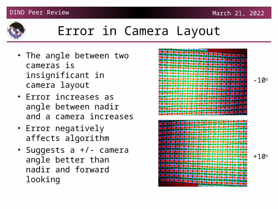
Error in Camera Layout
• The angle between two cameras is insignificant in camera layout
• Error increases as angle between nadir and a camera increases
• Error negatively affects algorithm
• Suggests a +/- camera angle better than nadir and forward looking
-10o
+10o
DINO Peer Review April 18, 2023
Camera Layout
• Third camera preferable to normalize +/- camera views
• Can obtain nadir camera view with – Two cameras– Multiple pictures– Large field of view (dependant on number of pictures
taken)
• Can have lower resolution in vertical direction
DINO Peer Review April 18, 2023
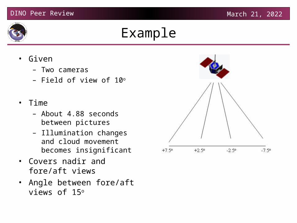
Example
• Given– Two cameras
– Field of view of 10o
• Time – About 4.88 seconds between
pictures
– Illumination changes and cloud movement becomes insignificant
• Covers nadir and fore/aft views• Angle between fore/aft views
of 15o
DINO Peer Review April 18, 2023
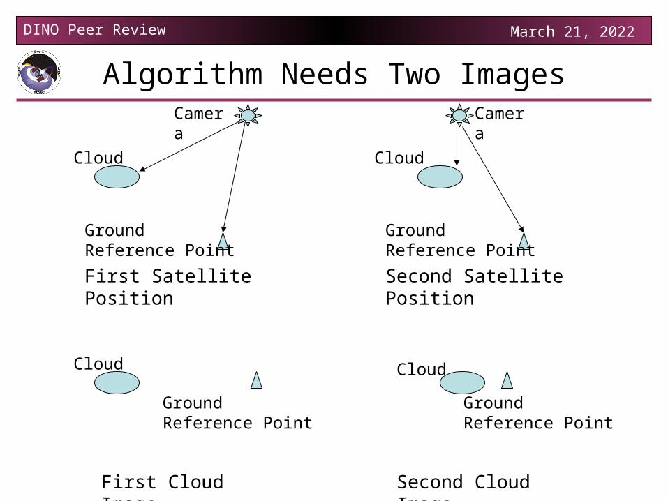
Algorithm Needs Two Images
Ground Reference Point
Cloud
Camera
Ground Reference Point
Cloud
Ground Reference Point
Cloud
Camera
Ground Reference Point
Cloud
First Satellite Position Second Satellite Position
First Cloud Image Second Cloud Image
DINO Peer Review April 18, 2023
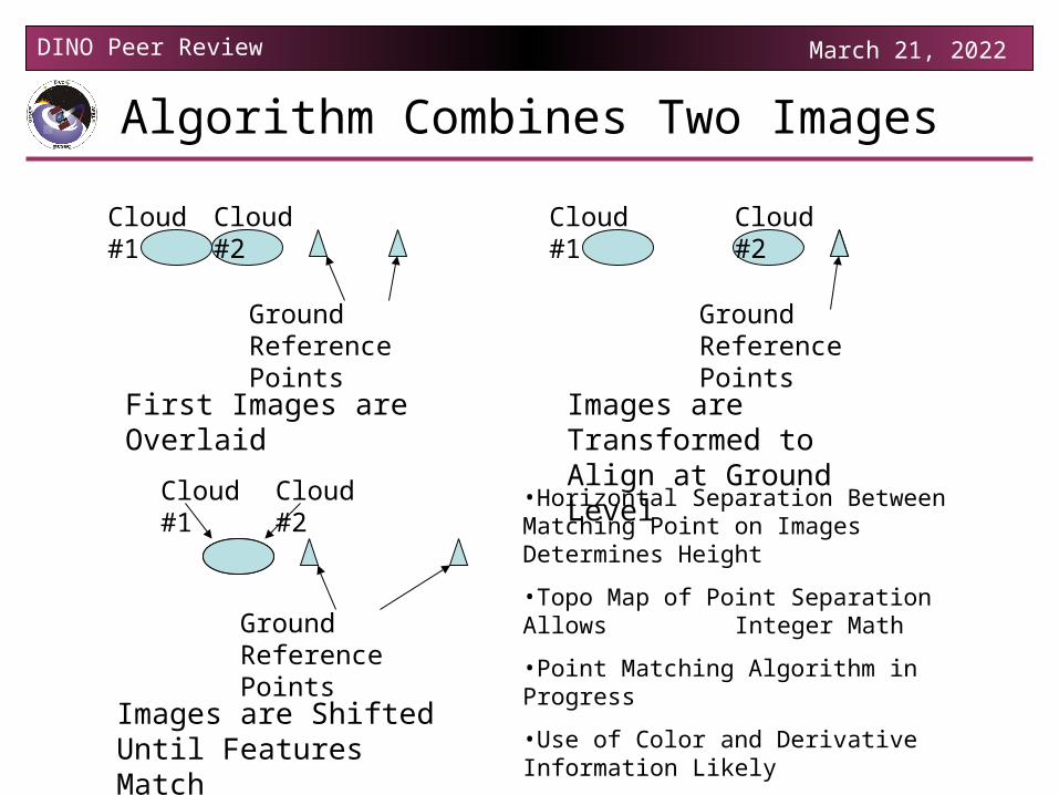
Algorithm Combines Two Images
Cloud #1
Ground Reference Points
Cloud #2
First Images are Overlaid
•Horizontal Separation Between Matching Point on Images Determines Height
•Topo Map of Point Separation Allows Integer Math
•Point Matching Algorithm in Progress
•Use of Color and Derivative Information Likely
Cloud #1 Cloud #2
Images are Transformed to Align at Ground Level
Ground Reference Points
Cloud #1
Ground Reference Points
Cloud #2
Images are Shifted Until Features Match
DINO Peer Review April 18, 2023
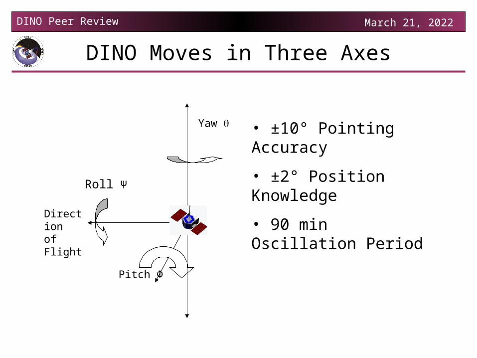
DINO Moves in Three Axes
Pitch Φ
Yaw
Roll Ψ
Direction of Flight
• ±10° Pointing Accuracy
• ±2° Position Knowledge
• 90 min Oscillation Period
DINO Peer Review April 18, 2023
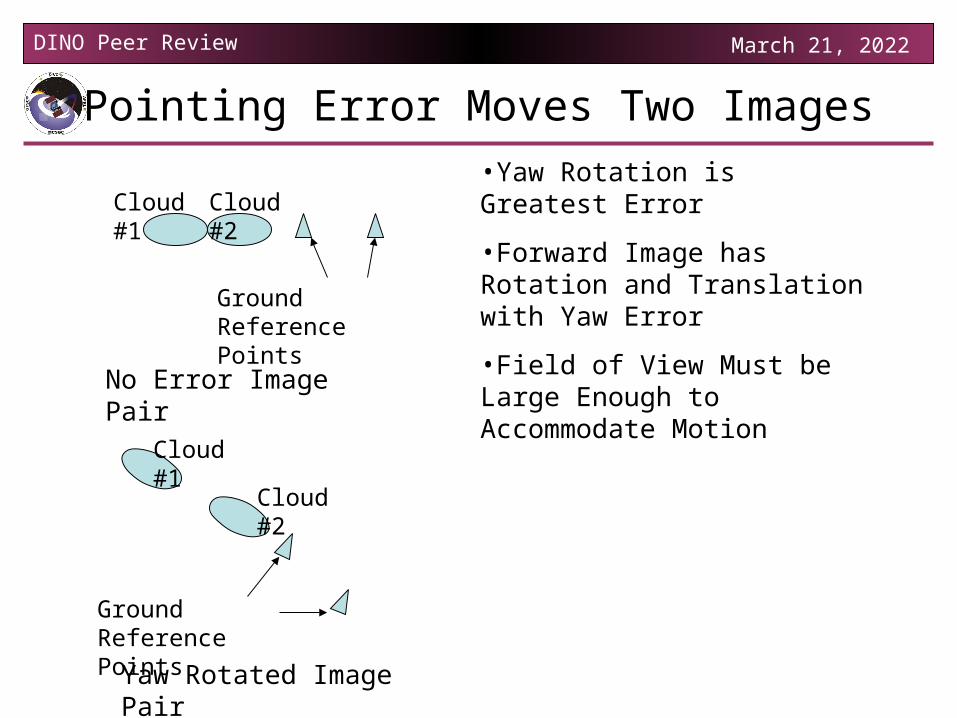
Pointing Error Moves Two Images
Cloud #1
Ground Reference Points
Cloud #2
Yaw Rotated Image Pair
•Yaw Rotation is Greatest Error
•Forward Image has Rotation and Translation with Yaw Error
•Field of View Must be Large Enough to Accommodate Motion
Ground Reference Points
Cloud #1 Cloud #2
No Error Image Pair
DINO Peer Review April 18, 2023
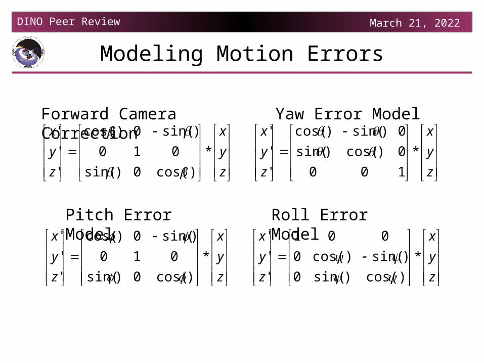
Modeling Motion Errors
z
y
x
z
y
x
*
)cos(0)sin(
010
)sin(0)cos(
'
'
'
z
y
x
z
y
x
*
)cos(0)sin(
010
)sin(0)cos(
'
'
'
z
y
x
z
y
x
*
100
0)cos()sin(
0)sin()cos(
'
'
'
z
y
x
z
y
x
*
)cos()sin(0
)sin()cos(0
001
'
'
'
Forward Camera Correction Yaw Error Model
Roll Error ModelPitch Error Model
DINO Peer Review April 18, 2023
Science Algorithm is Under Way
• Basic Algorithm Determined
• Floating Point Math Avoided
• Topo Map in Pixel Distance Saves Bandwidth
• Point Matching needs Work
• Finalizing Motion Correction Technique
• Pseudo-Code Needed• Testing Needed• Final Write-up Needed• Implementation in
Software not started
DINO Peer Review April 18, 2023
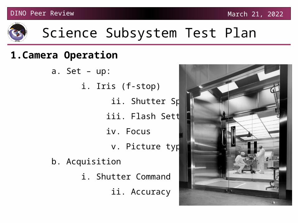
Science Subsystem Test Plan
1.Camera Operation
a. Set – up:
i. Iris (f-stop)
ii. Shutter Speed
iii. Flash Setting
iv. Focus
v. Picture type (Mode)
b. Acquisition
i. Shutter Command
ii. Accuracy
DINO Peer Review April 18, 2023
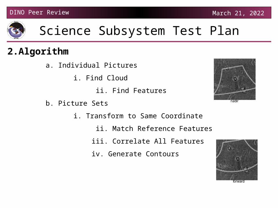
Science Subsystem Test Plan
2.Algorithma. Individual Pictures
i. Find Cloud
ii. Find Features
b. Picture Sets
i. Transform to Same Coordinate
ii. Match Reference Features
iii. Correlate All Features
iv. Generate Contours
DINO Peer Review April 18, 2023
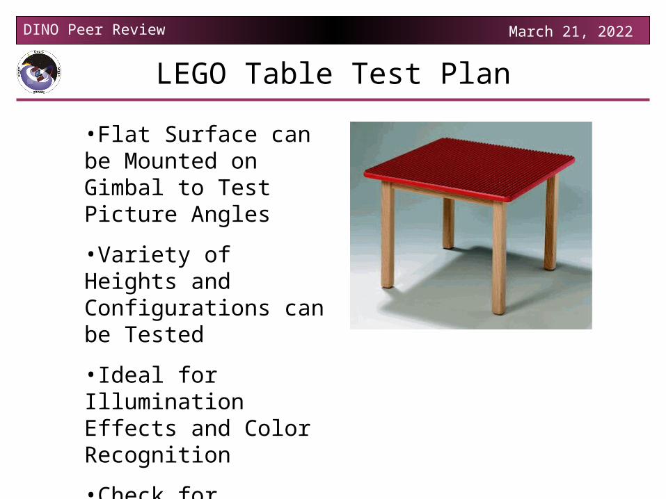
LEGO Table Test Plan
•Flat Surface can be Mounted on Gimbal to Test Picture Angles
•Variety of Heights and Configurations can be Tested
•Ideal for Illumination Effects and Color Recognition
•Check for donation from LEGO
DINO Peer Review April 18, 2023
Commands and Sensors
• Commands from C&DH– Set up cameras– Turn on/off camera #1– Turn on/off camera #2– Take a picture– Retrieve pictures– Clear memory
• Sensors– Possible Thermistor
DINO Peer Review April 18, 2023
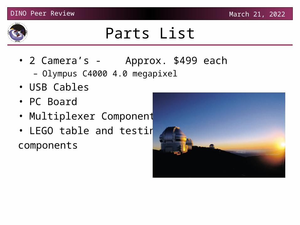
Parts List
• 2 Camera’s - Approx. $499 each– Olympus C4000 4.0 megapixel
• USB Cables• PC Board• Multiplexer Components• LEGO table and testing
components
DINO Peer Review April 18, 2023
Decisions Not Yet Made
• Camera angle on structure– Time between pictures
• Yaw control needed• How many pictures are
needed to determine along track wind
• What is the time delay between images
DINO Peer Review April 18, 2023
Issues and Concerns
• Camera– Problem
• The camera we are currently using doesn’t have software for USB
– Solution• We can write our own software for USB or design an interface to the flash
card
• Determining Camera angles– Depends on algorithm used
• Determining when is a good time to take pictures– Determining whether it is a good picture
• We can generate topographic maps, but they may be cloudless scenes• Probably will use color information
• Time between pictures– Time we have to take pictures vs. time we need to take pictures
DINO Peer Review April 18, 2023
Questions?


![RW]LP 0LQ +DOHY :KR·V LV LW - Weeblyhayotzim.weebly.com/uploads/2/3/6/5/23653986/ki_tavo.pdf · 7kh 0dwhk (iud\lp zulwhv wkdw lw lv edvhg rq d 0lg udvk lq (vwkhu zklfk uhdgv wkdw](https://img.pdfslide.us/doc/110x75/5c91d2aa09d3f20e358b86d5/rwlp-0lq-dohy-krv-lv-lw-7kh-0dwhk-iudlp-zulwhv-wkdw-lw-lv-edvhg-rq.jpg)


![RW]LP 0LQ +DOHY &KLQXFK )RU /LIHhayotzim.weebly.com/uploads/2/3/6/5/23653986/lech_lecha.pdf · 7kh 6kddu (iud\lp vkddu vli whdfkhv wkdw rqh pxvw zhdu d wdolv e\ 0lqfkd zkhq jhwwlqj](https://img.pdfslide.us/doc/110x75/5e63d77b41313f3c594de251/rwlp-0lq-dohy-klqxfk-ru-7kh-6kddu-iudlp-vkddu-vli-whdfkhv-wkdw-rqh-pxvw.jpg)