Embed Size (px)
Citation preview
20 21
Bulletin 05A01A01-01E
Digital Indicating ControllersSELECTION GUIDE
Indicating ControllersProcess ControllerProgram ControllersIndicators with AlarmsManual Setters
LR67174C
R
APPROVED
F M
EthernetEthernetEthernet
EthernetEthernetEthernet
Digital Indicating Controller
Digital Indicating Controller
Ethernet Arrester AR2
DAQSTATIONCX1000/CX2000
DAQSTATIONDX100/DX200
●GateModbus is a software interface for connecting devices that support the Modbus protocol with DAQLOGGER data logging software.Allows connection of controllers, power monitors, and signal conditioners to the network (Modbus/TCP) for a small scale instrumentation system that can be set up quickly.
●Reads the input and holding registers from up to 200 channels of various measuring instruments.
●Supports the Ethernet (Modbus/TCP protocols)●AddObserver monitor design software, an add-on for DAQLOGGER, lets
you create the custom monitors that are optimal for your measuring environment.
Ethernet(10Base-T)
NetworkData Acquisition
Data Server
<Example for Connection>
DAQWORXDAQWORX is an integrated data acquisition software package that is highlyscalable—it will respond flexibly to constant market changes. Combine DAQWORXwith Yokogawa recorders, data acquisition stations and units, instrumentation, andmeasuring instruments to build a user-friendly, PC-based data acquisition system.
With its three classes of software components—Base, Add-on and Gate—DAQWORXwill support changes to your system in response to future market demands. Leavingyour existing data acquisition system unmodified, you can simply incorporate ourrecorders, data acquisition units, and high-value-added software to tailor your systemfor specific needs.
• Data Acquisition ComponentsThe “Base” software components require neither technical expertise norprogramming, enabling you to easily set up hardware and start operating your dataacquisition system as soon as possible.
• High-Value-Added ComponentsThe “Add-on” software components offer advanced functionssuch as customizedwindows, monitoring clients, multi-logging, and data acquisition triggerconditioning.
• Interface ComponentsThe “Gate” software components enable data acquisition using power measuringinstruments and Modbus devices in combination with data acquisition units. Withthese components, you can quickly connect OPC servers and network cameras.
• DataBrowserEasily and quickly search files and display results in waveform
– Display measured data of different interval and different models on the sametime axis
– Easy data comparison based on the first data or trigger point.
Software Component
Data Acquisition ComponentsDAQLOGGER: General-purpose medium-speed (1 s max.) data acquisition
supports to major data acquisition equipment modelsDAQ32Plus: High-speed (500 ms max.) data acquisition tool for use with
DARWINMXLOGGER: Ultra high-speed (10 ms max.) data acquisition tool for use with
DAQMASTERDAQEXPLORER: Automatic data file acquisition tool for use with DAQSTATION
and MobileCorderHigh-Value-Added Components
AddObserver: Graphical human-machine interface (HMI) for creatingmonitoringwindows for the operator
AddMulti: Acquires data through groups of channels on a group-by-groupbasis by combining various measurement conditions
AddTrigger: Performs advanced data logging using a wide variety of triggerconditions
DAQLOGGER Client:Networked remote monitoring client software for DAQLOGGER
DAQ32Plus Client:Networked remote monitoring client software for DAQ32Plus
AddObserver Runtime:Networked remote monitoring runtime software for AddObserver
Interface ComponentsGateEye: An interface for distributing images from network cameras to
DAQObserverGateOPC: An interface for data acquisition from OPC servers to
DAQLOGGERGateWT: An interface for data acquisition from WT-series power meters
to DAQLOGGERGateDX-P: An interface for data acquisition from DX100P/200P to
DAQLOGGERGateMODBUS: An interface for data acquisition from MODBUS devices to
DAQLOGGERGateMX100: An interface for data acquisition from MX100 to DAQLOGGER
orAdd-on software.
GateµR An Interface for data acquisition from µR10000 toDAQLOGGER.
GateCONTROL Temperature controller (Green/UT100) and JUXTA(VJ series)can be easilyconnected to DAQLOGGER.
DAQWORX
Subject to change without notice.[Ed : 02/b] Copyright ©2003
Printed in Japan, 506(KP)
YOKOGAWA ELECTRIC CORPORATIONNetwork Solutions Business Div./Phone: (81)-422-52-7179, Fax: (81)-422-52-6793E-mail: [email protected]
YOKOGAWA CORPORATION OF AMERICA Phone: (1)-770-253-7000, Fax: (1)-770-251-2088YOKOGAWA EUROPE B.V. Phone: (31)-33-4641806, Fax: (31)-33-4641807YOKOGAWA ENGINEERING ASIA PTE. LTD. Phone: (65)-62419933, Fax: (65)-62412606 RS-14E
2 3
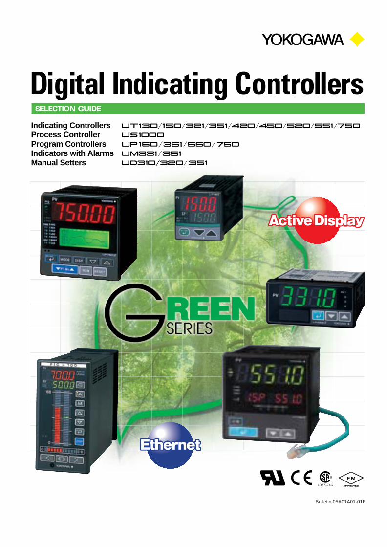
A Complete Range of Exceptional Controllers
UP351Program Controller
with Active Color PV Display
UP550Program Controller
UP750Program Controller
UM351Indicator with Alarms
with Active Color PV Display
UT351 UT450Indicating Controller
UT551 UT750Indicating Controller
US1000Process Controller
(72�144mm)
UT130Indicating Controller
(Unit:mm)UT150
Indicating Controller
UP150Program Controller
Select the One Suitable for Your Needs from YOKOGAWA Digital Indicating Controllers
96 � 96
(1/4DIN)
UM331Indicator with Alarms
with Active Color PV Display
UT321Indicating Controller
with Active Color PV Display
UT420Indicating Controller
UT520Indicating Controller
LL100,LL1100Parameters Setting Tool
LL200,LL1200Custom Computation
Building Tool
48 � 96
(1/8DIN)
48 � 48
(1/16DIN)
Indicating Controller with Ethernet& Active Color PV Display
Indicating Controller with Ethernet& Active Color PV Display
4 5
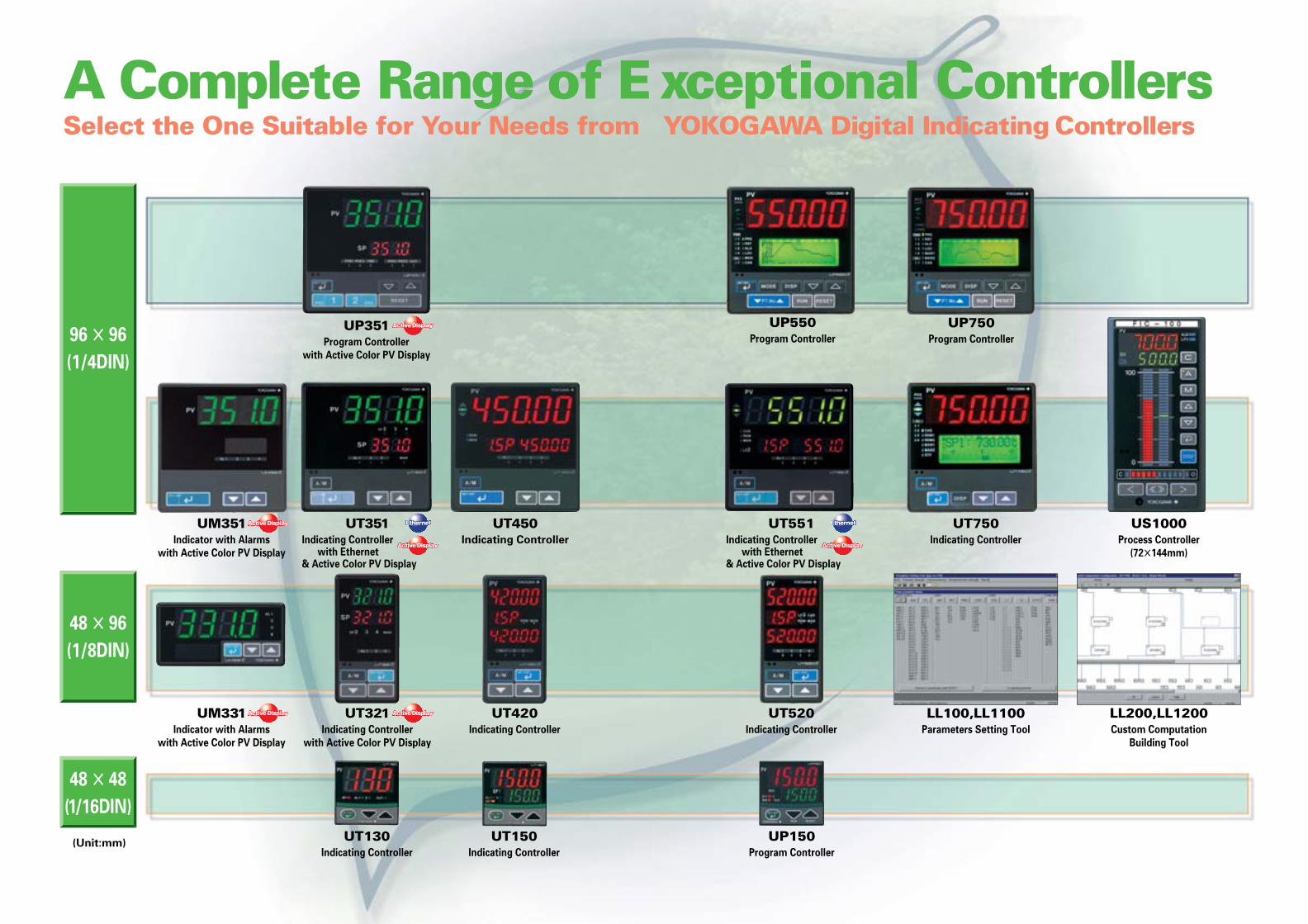
� Electric furnace � Heating/cooling control � Drive the control motor
AlarmsRetransmission
output
Electric furnace
UT450
4 to 20 mA DC
YP series thyristorSCR
UT551
Heating(4 to 20 mA DC signal)
Thermocouple
Heating unit
Cooling (relay signal)
Coolingwater
YP series thyristor
SCR
UP550
Gas
Air
Burner
Feedback
Controlmotor
Thermocouple
Recorder
Thermocouple
Alarm output
Retransmission output(4 to 20 mA DC)
Thermocouple
UM331/UM351
µR series recorder
� Oven temperature monitor� Carbon Potential control � Vacuum sintering furnace control
O2
Signal
Oxygensensor
UT750
Customcomputation
Vacuum sinteringfurnace
UP750
SCR
Control
Radiationthermometer
Thermocouple
PV switching
WithdrawalcommandRadiation
thermometer
Withdrawalcommand
O2
Temp.
Furnace
Burner control
Furnace Temp.TC
Air
Natural gas
Endo gas
Materials
UT2800
Heating/cooling
Graphic display
The UT2800 series is optimum for 3- to 4-zone heating/cooling control.
Communication
PLC
Heater
Cooling water
Cold water
SSR
CT
Relay output(cooling side)
Heater burnout alarm
Voltage pulse output(heating side)
UT150
� Control of extruders
Dry-bulbtemperature
UP750
SCR
SCR
Alarm output PLC or switch
UT450
UT750
µR series recorder
Thermocouple4 to 20 mA DC
SCR
� External setpoints switching � Dual-loop control � Temperature and Humidity control
Wet-bulbtemperature
Control 1 Control 2
CoolantCoolant
Rawmaterial
For electronics and semiconductor manufacturing
M
Waste waterpH signal
Waste waterflow rate pH sensor
µR series recorder
Neutralizer
Neutralized waste water
4 to 20 mA
Primary PV input
Flow meter
Hot water
TC
Secondary PV input
UT750 US1000
US1000
� Cascade control � Feed-forward control
� Combustion control� Backup control
Fuel flowcontroller
Mastercontroller
Fuel
Air
Air flowcontroller
DCS or PLC
US1000
MV
Fail signal
PV
US1000 executesbackup controlwhen DCS or PLC fail.
Product
Raw material
Control
Cooling water
Steam
Heating/coolingcontrol
UT320
UP750
� Control of cleaning equipment � Control of reflow furnaces � Temperature control with high accuracy
SCR
Timer Time Lapse signal
Switch-on signal
Cleaning fluid temperature
4 to 20 mA
UT150
Heater
Raise Lower
For food and pharmaceutical industries
Chamber
Remote SP
Heat source
Fan
eggs
Spray UT450
UT450
PLC
WaterPharmaceuticals
UP351
SCR
Wrapping machineWrapping machine
Communication
Wrappingmachinecontrol
PLCSealingtemperaturetemperatureSealingtemperature Roll
temperature
UT130
HeaterHeaterFeedcontrol
� Temperature control for sterilization � Incubator control � Food wrapping machine
Heater
Wrapping machine
Feedcontrol
For industrial furnace control
For plastics processing and forming
For environmental testing and control
For food and pharmaceutical industries
Optimum controllers for process control
For electronics and semiconductor manufacturing
6 7
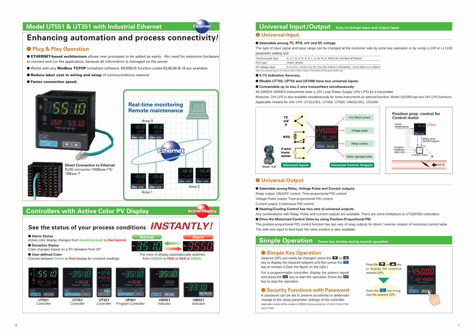
Enhancing automation and process connectivity!
� Plug & Play Operation
� ETHERNET-based architecture allows new processes to be added as easily. –No need for extensive hardware to connect and run the application, because all information is managed on the server.
� Works with any Modbus TCP/IP compliant software. MODBUS function codes 03,06,08 & 16 are available.
� Reduce labor cost in wiring and setup of communications network.
� Faster connection speed.
Direct Connection to Ethernet
RJ45 connector-100Base-TX/10Base-T
Real-time monitoringRemote maintenance
Area-3
Area-1
Area-2
� Security Functions with PasswordA password can be set to prevent accidental or deliberatechange to the setup parameter settings of the controller.Applicable models:All the models of GREEN Series (except for UT130,UT150,UT152
and UT155)
� Simple Key OperationSetpoint (SP) can easily be changed: press the or key to display the required setpoint and then press the SET/ENT
key to resister it.(See the figure on the right.)
For a programmable controller, display the pattern signaland press the RUN key to start the operation. Press the RESET
key to stop the operation.
� Universal Input
� Selectable among TC, RTD, mV and DC voltage.
The type of input signal and input range can be changed at the customer side by some key operation or by using LL100 or LL1100
parameter setting tool.
� 0.1% Indication Accuracy.
� Models UT750, UP750 and US1000 have two universal inputs.
� Connectable up to two 2-wire transmitters simultaneously.
All GREEN SERIES instruments have a 15V Loop Power Supply (15V LPS) for a transmitter.
Moreover, 24V LPS is also available simultaneously for some instruments as optional function. Model US1000 has two 24V LPS functions.
Applicable models for 24V LPS: UT321/351, UT450, UT550, UM331/351, US1000
Press the or keyto display the requiredsetpoint (SP).
Press the SET/ENT
key to reg-ister the setpoint (SP).
Thermocouple Type : K, J, T, B, S, R, N, E, L, U, W, PL-2, PR20-40, W97Re3-W75Re25
RTD Type : Pt100, JPt100
DC Voltage Input : 0.4 to 2V, 1 to 5V, 0 to 2V, 0 to 10V, 0.00 to 1.25V(Note), -10 to 20mV, 0 to 100mVNote: For universal input 2 of UT420,UT450,UT520,UT550,UT750,UP550,UP750 and US1000 only.
Model : EJA
4 to 20mA current
Voltage pulse
Relay contact
Motor operated valve
Universal Control OutputsUniversal Inputs
TCmVV
RTD
2-wiretrans-mitter
� Universal Output
� Selectable among Relay, Voltage Pulse and Current outputs.
Relay output: ON/OFF control, Time-proportional PID control
Voltage Pulse output: Time-proportional PID control
Current output: Continuous PID control
� Heating/Cooling Control has two sets of universal outputs.
Any combinations with Relay, Pulse and Current outputs are available. There are some limitations to UT320/350 controllers.
� Drive the Motorized Control Valve by using Position-Proportional PID.
The position-proportional PID control function has two sets of relay outputs for direct / reverse rotation of motorized control valve.
The side wire input to feed back the valve position is also available.
Model UT551 & UT351 with Industrial Ethernet Universal Input/Output Easy-to-change input and output types
Simple Operation Fewer key strokes during normal operation
� Alarm Status
Active color display changes from Green(normal) to Red(alarm)
� Deviation Status
Color changes based on a PV deviation from SP
� User-defined Color
Choose between Green or Red display for constant readingsThe color of display automaticcally switches
from GREEN to RED or RED to GREN.
See the status of your process conditions INSTANTLY!Normal Alarm
UT351Controller
UT551Controller
UT321Controller
UP351Program Controller
UM351Indicator
UM331Indicator
Controllers with Active Color PV Display
Motor driveOn/Off outputs
UT551Roomtemperature
Positionfeedbackslide wire
Control motor
Hot air
Position prop. control forControl motor
8 9
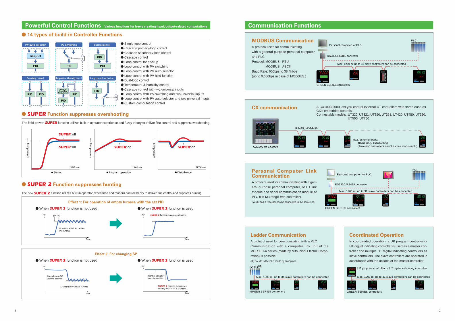
� Single-loop control� Cascade primary-loop control� Cascade secondary-loop control� Cascade control� Loop control for backup� Loop control with PV switching� Loop control with PV auto-selector� Loop control with PV-hold function� Dual-loop control� Temperature & humidity control� Cascade control with two universal inputs� Loop control with PV switching and two universal inputs� Loop control with PV auto-selector and two universal inputs� Custom computation control
� 14 types of build-in Controller Functions
PV auto-selector
SELECT
PID
Dual-loop control
PID
PV switching
PID
Temperature & humidity control
Cascade control
Loop control for backup
PID
PID
PIDPID
PID
PID
RelativeHumidity
Calculation
PV
Operation with load causesPV hunting.
Time
SP PV
Changing SP causes hunting.
PV
Time
Control using SPwith the set PID.
PV
Time
SUPER 2 function suppresses hunting.
PV
Time
Control using SPwith the set PID.
SUPER 2 function suppresses hunting even if SP is changed.
� SUPER Function suppresses overshooting
The field-proven SUPER function utilizes built-in operator experience and fuzzy theory to deliver fine control and suppress overshooting.
The new SUPER 2 function utilizes built-in operator experience and modern control theory to deliver fine control and suppress hunting.
Startup Program operation
TimeTimeTime
Tem
perature
Tem
perature
Tem
perature
Disturbance
SUPER:off
SUPER:on SUPER:on SUPER:on
� When SUPER 2 function is not used � When SUPER 2 function is used
� When SUPER 2 function is not used � When SUPER 2 function is used
Effect 1: For operation of empty furnace with the set PID
Effect 2: For changing SP
MODBUS Communication
A protocol used for communicating
with a general-purpose personal computer
and PLC.
Protocol: MODBUS RTU
MODBUS ASCII
Baud Rate: 600bps to 38.4kbps
(up to 9,600bps in case of MODBUS.)
Personal computer, or PLC
RS232C/RS485 converter
GREEN SERIES controllers
Max. 1200 m; up to 31 slave controllers can be connected
PLC
CX communication A CX1000/2000 lets you control external UT controllers with same ease asCX’s embedded controls.Connectable models :UT320, UT321, UT350, UT351, UT420, UT450, UT520,
UT550, UT750
Personal Computer LinkCommunicationA protocol used for communicating with a gen-
eral-purpose personal computer, or UT link
module and serial communication module of
PLC (FA-M3 range-free controller).
FA-M3 and a recorder can be connected in the same line.
Personal computer, or PLC
RS232C/RS485 converter
GREEN SERIES controllers
Max. 1200 m; up to 31 slave controllers can be connected
PLC
Coordinated Operation
In coordinated operation, a UP program controller or
UT digital indicating controller is used as a master con-
troller and multiple UT digital indicating controllers as
slave controllers. The slave controllers are operated in
accordance with the actions of the master controller.
Ladder Communication
A protocol used for communicating with a PLC.
Communication with a computer link unit of the
MELSEC-A series (made by Mitsubishi Electric Corpo-
ration) is possible.
(�) FA-M3 is the PLC made by Yokogawa.
FA-M3(�)
Max. 1200 m; up to 31 slave controllers can be connected
GREEN SERIES controllers
UP program controller or UT digital indicating controller
GREEN SERIES controllers
Max. 1200 m; up to 31 slave controllers can be connected
Powerful Control Functions Various functions for freely creating input/output-related computations Communication Functions
Max. external loops: 4(CX1000), 16(CX2000) (Two-loop controllers count as two loops each.)CX1000 or CX2000
RS485, MODBUS
� SUPER 2 Function suppresses hunting
10 11
Contact Inputs (/EX)
PID Control AT
Alarm & TimerOutputs
(/AL)
AL2AL1
Rate-of-changeLimiter
SP2SP1
Manual
SP selection
STOP/RUN Switching
Timer ONsignal
AUTO/MAN
DI1 DI2
Bias & Filtering
PV Input
Relay Contact Outputs
Reverse MV Direct MV
Estimated valve position
Pre-set Output
Functions Selector
Comparator
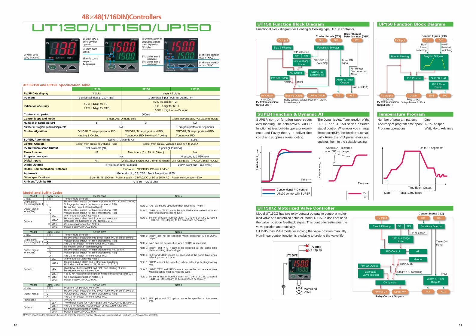
48�48(1/16DIN)Controllers
Lit when SP isbeing displayed.
Lit when SP2 isbeing used foroperation.
Lit when alarmoccurs.
Lit while controloutput isbeing output.
Lit when the segment no.or remaining segmenttime is displayed onSP display.
EV1: Lit when event 1is activated.
EV2: Lit when event 2is activated.
Lit while the operationmode is “HOLD”.
Lit while the operationmode is “RUN”.
PV/SP Data display
PV Input
Indication accuracy
Control scan period
Control loops and mode
Number of Setpoint (SP)
Number of Program patterns/segments
Control Algorithm
SUPER, Auto tuning
Control Outputs
PV Retransmission Output
Timer function
Program time span
Digital Inputs
Digital Outputs
RS485 Communication Protocols
Approvals
Other specifications
Ambient T, Limits RH
500ms
1 loop, AUTO mode only 1 loop, RUN/RESET, HOLD/Cancel HOLD
SUPER
NA
0 second to 1,599 hour
2 (RUN/RESET, HOLD/Cancel HOLD)
2 (PV event and Time event)
Two-wire, MODBUS, PC-link, Ladder
General = UL, CE, CSA Front Protection= IP65
Size=48*48*100mm, Power supply = 24VAC/DC or 90 to 264V AC, Power consumption=8VA
0 to 50 , 20 to 90%
UT130/150 and UP150 Specification TableUT130
3 digits
1 universal input (TCs, RTDs)
�2˚C �1digit for TC
�1˚C �1digit for RTD
UP150UT150
4 digits / 4 digits
1 universal input (TCs, RTDs, mV, V)
�2˚C �1digit for TC
�1˚C �1digit for RTD
�0.3%�1digit for mV/V input
1
ON/OFF, Time-proportional PID,
Heating & Cooling
2
ON/OFF, Time-proportional PID,
Continuous PID, Heating & Cooling
NA
1 program pattern/16 segments
ON/OFF, Time-proportional PID,
Continuous PID
NA
SUPER, Dynamic AT
Select from Relay or Voltage Pulse
Not available (NA)
NA
NA
Two timers (0 to 99min.59sec)
2 (sp1/sp2, RUN/STOP, Timer function)
Select from Relay, Voltage Pulse or 4 to 20mA
1 point (4 to 20mA)
NA
2 (Alarm or Timer outputs)
Model Suffix Code NotesDescriptionTemperature controllerRelay contact output (for time-proportional PID or on/off control)Voltage pulse output (for time-proportional PID)
Power Supply 24VDC/24VACCommunication function Note 2
/V24
Power Supply 24VDC/24VAC/V24
No cooling output (Standard type)Relay contact output (for time-proportional PID)Voltage pulse output (for time-proportional PID)Alarm outputs (2 points) Note 1Heater burnout alarm and 2 other alarm outputs (includes the functions of /AL) Notes 1, 2, 3
-R- � �
-VNRV
/AL
/HBA
/RS
UT130Output signal(for heating) Note 1
Output signalfor cooling
Options
"/AL" cannot be specified when specifying "/HBA" .
"/HBA" and "/RS" cannot be specified at the same time when selecting heating/cooling type.
Sensor of heater burnout alarm is CTL-6-S or CTL-12-S36-8 (URD Co., Ltd., Japan) To be purchased separately
Note 1:
Note 2:
Note 3:
- � �Model Suffix Code Description
Temperature controllerRelay contact output(for time-proportional PID or on/off control)Voltage pulse output (for time-proportional PID)4 to 20 mA output (for continuous PID) Note1No cooling output (Standard type)Relay contact output (for time-proportional PID control)Voltage pulse output (for time-proportional PID)4 to 20 mA output (for continuous PID)
4 to 20 mA retransmission output of measured value (PV) Notes 3, 5
Switchover between SP1 and SP2, and starting of timerby external contacts Notes 4, 6
Heater burnout alarm and 2 other alarm outputs (includes the functions of /AL) Notes 1, 2, 3, 6, 7
Alarm outputs (2 points) Note 2
-R-V-A
NRVA
Communication function Notes 4, 6
/EX
/HBA
/AL
UT150
Output signal(for heating) Note 1
Output signalfor cooling
Options
Notes
Note 1:
Note 2:
Note 3:
Note 4:
Note 5:
Note 6:
Note 7:
"/HBA" can not be specified when selecting."-A:4 to 20mA output".
"/AL" can not be specified when "/HBA" is specified.
"/HBA" and "/RET" cannot be specified at the same time when selecting standard type.
"/EX" and "/RS" cannot be specified at the same time when selecting standard type.
"/RET" cannot be specified when selecting heating/cooling type.
"/HBA","/EX" and "/RS" cannot be specified at the same time when selecting heating / cooling type.
Sensor of heater burnout alarm is CTL-6-S or CTL-12-S36-8 (URD Co., Ltd., Japan) To be purchased separately
/RET/RS
Power Supply 24VDC/24VAC/V24
- � �Model Suffix Code Description
Program Temperature controllerRelay contact output(for time-proportional PID or on/off control)Voltage pulse output (for time-proportional PID)4 to 20 mA output (for continuous PID)Always N
4 to 20 mA retransmission output of measured value (PV)Two digital inputs for RUN/RESET and HOLD/CANCEL Note 1
-R-V-A
N
Communication function Notes 1
/EX
UP150
Output signal
Options
Fixed code
Notes
Note 1: /RS option and /EX option cannot be specified at the same time.
/RET/RS
Model and Suffix Codes
� When specifying the /RS option, be sure to order the required number of copies of Communication Functions User's Manual separeately.
�
�
�
UT150 Function Block DiagramFunctional block diagram for Heating & Cooling type UT150 controller.
Contact Inputs (/EX)
DI1
SUPER & AT
PV & TimeEvents
PV Output EV2EV1
Relay contact,Voltage Puse or 4 - 20mA
DI2
Run/Reset
switching
PV Input
4 to 20mAPV Retransmission Output (/RET)
Output
Program Setpoint
Hold/Re-startswitching
Bias & Filtering
PID Control
RUN
Bias & Filtering
Contact Inputs (/EX)DI1
PID Control SUPER &Dynamic AT
Heater Current Detection Input (/HBA)
For HeaterDisconnectionAlarm
Alarm & TimerOutputs
(/AL or /HBA)
PV Output
Relay contact, Voltage Puse or 4 - 20mAfor each output
Functions Selector
Rate-of-changeLimiter
SP2SP1
DI2
SP selection
STOP/RUNswitching
Timer ONsignal
STOP
PV Input
4 to 20mAPV Retransmission Output (/RET)
Heating Output Cooling Output
Pre-set Output
CT
AL2AL1
SUPER Function & Dynamic AT
UP150 Function Block Diagram
Temperature ProgramSUPER control function suppressesovershooting. The field-proven SUPERfunction utilizes build-in operator experi-ence and Fuzzy theory to deliver finecotrol and suppress overshooting.
Number of program pattern: OneAccuracy of program time span: +/-2% of spanProgram operations: Wait, Hold, Advance
Conventional PID controlUT100 control with SUPER
Time
Tem
perature
The Dynamic Auto Tune function of theUT130 and UT150 series assuresstabel control. Whenever you changethe setpoint(SP), the function automati-cally turns the PID parameters andupdates them to the suitable setting.
Start Max. 1,599 hours
Time Event Output
Up to 16 segmentsDynamic AT is startedwhen SP is changed.
PVSP
Time
Tem
perature
UT150/Z Motorized Valve ControllerModel UT150/Z has two relay contact outputs to control a motor-ized valve or a motorized actuator. Model UT150/Z does not needthe valve position feedback signal. This controller estimates thevalve position automatically.UT150/Z has MAN mode for moving the valve position manually.Non-linear control function is available to prolong the valve life.
AlarmsOutputs
MotorizedValve
UT150/Z
12 13
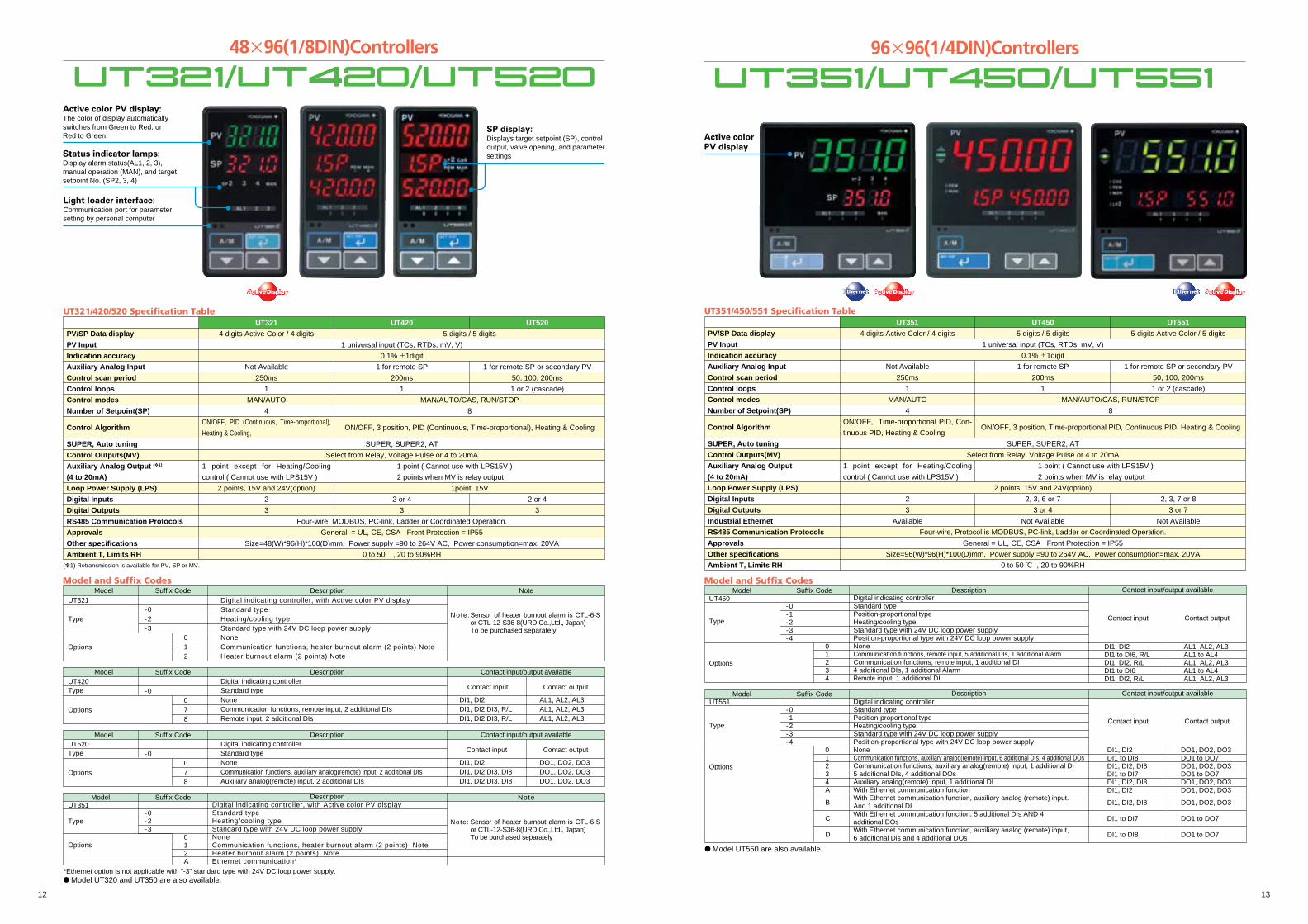
48�96(1/8DIN)Controllers
Status indicator lamps:Display alarm status(AL1, 2, 3),manual operation (MAN), and targetsetpoint No. (SP2, 3, 4)
Light loader interface:Communication port for parameter setting by personal computer
SP display:Displays target setpoint (SP), controloutput, valve opening, and parametersettings
Active color PV display:The color of display automaticallyswitches from Green to Red, orRed to Green.
96�96(1/4DIN)Controllers
Active colorPV display
PV/SP Data display
PV Input
Indication accuracy
Auxiliary Analog Input
Control scan period
Control loops
Control modes
Number of Setpoint(SP)
Control Algorithm
SUPER, Auto tuning
Control Outputs(MV)
Auxiliary Analog Output (�1)
(4 to 20mA)
Loop Power Supply (LPS)
Digital Inputs
Digital Outputs
RS485 Communication Protocols
Approvals
Other specifications
Ambient T, Limits RH
UT321
4 digits Active Color / 4 digits
1 universal input (TCs, RTDs, mV, V)
0.1% �1digit
Not Available
250ms
1
MAN/AUTO
4
ON/OFF, PID (Continuous, Time-proportional),
Heating & Cooling,
SUPER, SUPER2, AT
Select from Relay, Voltage Pulse or 4 to 20mA
1 point except for Heating/Cooling
control ( Cannot use with LPS15V )
2 points, 15V and 24V(option)
2
3
Four-wire, MODBUS, PC-link, Ladder or Coordinated Operation.
General = UL, CE, CSA Front Protection = IP55
Size=48(W)*96(H)*100(D)mm, Power supply =90 to 264V AC, Power consumption=max. 20VA
0 to 50 , 20 to 90%RH
UT321/420/520 Specification Table
(�1) Retransmission is available for PV, SP or MV.
UT420
5 digits / 5 digits
1 for remote SP
200ms
1
MAN/AUTO/CAS, RUN/STOP
8
ON/OFF, 3 position, PID (Continuous, Time-proportional), Heating & Cooling
1 point ( Cannot use with LPS15V )
2 points when MV is relay output
1point, 15V
2 or 4
3
UT520
1 for remote SP or secondary PV
50, 100, 200ms
1 or 2 (cascade)
2 or 4
3
UT351
4 digits Active Color / 4 digits
1 universal input (TCs, RTDs, mV, V)
0.1% �1digit
Not Available
250ms
1
MAN/AUTO
4
ON/OFF, Time-proportional PID, Con-
tinuous PID, Heating & Cooling
SUPER, SUPER2, AT
Select from Relay, Voltage Pulse or 4 to 20mA
1 point except for Heating/Cooling
control ( Cannot use with LPS15V )
2 points, 15V and 24V(option)
2
3
Available
Four-wire, Protocol is MODBUS, PC-link, Ladder or Coordinated Operation.
General = UL, CE, CSA Front Protection = IP55
Size=96(W)*96(H)*100(D)mm, Power supply =90 to 264V AC, Power consumption=max. 20VA
0 to 50 : , 20 to 90%RH
PV/SP Data display
PV Input
Indication accuracy
Auxiliary Analog Input
Control scan period
Control loops
Control modes
Number of Setpoint(SP)
Control Algorithm
SUPER, Auto tuning
Control Outputs(MV)
Auxiliary Analog Output
(4 to 20mA)
Loop Power Supply (LPS)
Digital Inputs
Digital Outputs
Industrial Ethernet
RS485 Communication Protocols
Approvals
Other specifications
Ambient T, Limits RH
UT450
5 digits / 5 digits
1 for remote SP
200ms
1
MAN/AUTO/CAS, RUN/STOP
8
ON/OFF, 3 position, Time-proportional PID, Continuous PID, Heating & Cooling
1 point ( Cannot use with LPS15V )
2 points when MV is relay output
2, 3, 6 or 7
3 or 4
Not Available
UT351/450/551 Specification TableUT551
5 digits Active Color / 5 digits
1 for remote SP or secondary PV
50, 100, 200ms
1 or 2 (cascade)
2, 3, 7 or 8
3 or 7
Not Available
Model and Suffix CodesModel
UT321
Type
Options
Digital indicating controller, with Active color PV displayStandard typeHeating/cooling typeStandard type with 24V DC loop power supplyNoneCommunication functions, heater burnout alarm (2 points) NoteHeater burnout alarm (2 points) Note
Suffix Code Description Note
-0-2-3 0 1 2
ModelUT420Type
Options
Digital indicating controllerStandard typeNoneCommunication functions, remote input, 2 additional DIsRemote input, 2 additional DIs
DI1, DI2DI1, DI2,DI3, R/LDI1, DI2,DI3, R/L
AL1, AL2, AL3AL1, AL2, AL3AL1, AL2, AL3
Suffix Code Description Contact input/output available
Contact outputContact input-0 0 7 8
ModelUT520Type
Options
Digital indicating controllerStandard typeNoneCommunication functions, auxiliary analog(remote) input, 2 additional DIsAuxiliary analog(remote) input, 2 additional DIs
DI1, DI2DI1, DI2,DI3, DI8DI1, DI2,DI3, DI8
DO1, DO2, DO3DO1, DO2, DO3DO1, DO2, DO3
Suffix Code Description Contact input/output available
Contact outputContact input-0 0 7 8
Note:Sensor of heater burnout alarm is CTL-6-S or CTL-12-S36-8(URD Co.,Ltd., Japan)To be purchased separately
� Model UT320 and UT350 are also available.
ModelUT351
Type
Options
Digital indicating controller, with Active color PV displayStandard typeHeating/cooling typeStandard type with 24V DC loop power supplyNoneCommunication functions, heater burnout alarm (2 points) NoteHeater burnout alarm (2 points) NoteEthernet communication*
Suffix Code Description Note
-0-2-3 0 1 2 A
Note: Sensor of heater burnout alarm is CTL-6-S or CTL-12-S36-8(URD Co.,Ltd., Japan)To be purchased separately
*Ethernet option is not applicable with "-3" standard type with 24V DC loop power supply.
Model and Suffix Codes
ModelUT551 Digital indicating controller
Standard typePosition-proportional typeHeating/cooling typeStandard type with 24V DC loop power supplyPosition-proportional type with 24V DC loop power supplyNoneCommunication functions, auxiliary analog(remote) input, 6 additional DIs, 4 additional DOsCommunication functions, auxiliary analog(remote) input, 1 additional DI5 additional DIs, 4 additional DOsAuxiliary analog(remote) input, 1 additional DIWith Ethernet communication function With Ethernet communication function, auxiliary analog (remote) input. And 1 additional DIWith Ethernet communication function, 5 additional DIs AND 4 additional DOsWith Ethernet communication function, auxiliary analog (remote) input, 6 additional Dis and 4 additional DOs
DI1, DI2DI1 to DI8DI1, DI2, DI8DI1 to DI7DI1, DI2, DI8DI1, DI2
DI1, DI2, DI8
DI1 to DI7
DI1 to DI8
DO1, DO2, DO3DO1 to DO7DO1, DO2, DO3DO1 to DO7DO1, DO2, DO3DO1, DO2, DO3
DO1, DO2, DO3
DO1 to DO7
DO1 to DO7
Suffix Code Description Contact input/output available
Contact outputContact input
-0-1-2-3-4 0 1 2 3 4 A
B
C
D
Options
Type
ModelUT450
Type
Digital indicating controller Standard type Position-proportional type Heating/cooling typeStandard type with 24V DC loop power supplyPosition-proportional type with 24V DC loop power supplyNoneCommunication functions, remote input, 5 additional DIs, 1 additional AlarmCommunication functions, remote input, 1 additional DI4 additional DIs, 1 additional AlarmRemote input, 1 additional DI
DI1, DI2DI1 to DI6, R/LDI1, DI2, R/LDI1 to DI6DI1, DI2, R/L
AL1, AL2, AL3AL1 to AL4AL1, AL2, AL3AL1 to AL4AL1, AL2, AL3
Suffix Code Description Contact input/output available
Contact outputContact input
-0-1-2-3-4 0 1 2 3 4
Options
� Model UT550 are also available.
14 15
Excellent Control, Multifunction Controllers
ALM lamp
C / A / M mode keys
SV bar display
PV bar display
SV setting keys
MV operation keys
MV bar display
Status indicator lamps:Display loop-2 PV(PV 2),deviaton status (�, �, �), alarm status(AL 1, 2, 3, 4), cascade operation (CAS),remote operation (REM1, REM2),manual operation (MAN1, MAN2), andoperation stop (STP)
Light loader interface:Communication port forparameter setting by personalcomputer and customcomputation downloading
PV/SP Data display
PV Inputs
Indication accuracy
Auxiliary Analog Input
Control scan period
Control loops
Number of Setpoint (SP)
Control Algorithm
SUPER, Auto tuning
Custom Computation
Control Outputs (MV)
Auxiliary Analog Output (4 to 20mA)
Loop Power Supply
Digital Inputs
Digital Outputs
RS485 Communication Protocol
Front Protection
General Approvals
Power Supply, Consumption
Size, weight
Ambient T, Limits RH
UT750, US1000 Specification TableUT750
5 digits / 5 digits with LCD display
2 universal inputs (TCs, RTDs, mV, V)
0.1% �1digit
1 point
50, 100, 200, 500ms
1 or 2(cascade, dual)
8
ON/OFF, 3 position, PID (Continuous, Time-proportional), Heating & Cooling, Position-proportional PID
SUPER, SUPER2, AT
Standard
Select from 2 sets of Relays, Voltage Pulses or 4 to 20mA
1 point, 2 points when MV is relay output
1 point of 15V ( Cannot use with auxiliary analog output )
2 or 7
3 or 7
MODBUS, PC-link, Ladder, Coordinated Operation
IP55
UL, CE, CSA
90 to 264 V AC, max. 20VA
96(W)*96(H)*100(D)mm, 1kg
0 to 50 : , 20 to 90%RH
US1000
5 digits / 5 digits with Bar Graphs
SUPER, AT
Option
2 points of 24V
MODBUS, PC-link
IP65
CE, CSA, FM-non incendive
90 to 264 V AC, max. 25VA
72(W)*144(H)*149(D)mm, 0.8kg
Model and Suffix CodesModel
UT750
Type
Opt ions
Digital indicating controller Single-loop typePosition-proportional typeDual-loop typeNoneCommunication functions, auxiliary analog(remote) input
Suffix Code Description
-0-1-5 0 1
ModelUS1000
Type
Opt ions
Process controllerBasic typeEnhanced type(with custom computation)Position-proportional type(with custom computation)RS485 communication
�LPS:Loop power supply for transmitter.�The two contact points in the US1000-21 relay item are the relay output and feedback input.
Universal
122
Voltage111
Current121
Voltage111
Relay02
�2
Input277
Output377
�LPS122
Suff ix Codes Descr ipt ion Analog output ContactAnalog input
-00-11-21
/A10
DI1 to DI7DI1 to DI7
DO1 to DO7DO1 to DO7
Contact input/output available
Contact outputContact input
� Custom Computation for Sophisticated ControlCustom computation allows simple operation sequences and signal computations specific to the application to be speci-
fied, which the standard controller mode cannot deal with.
Input/output-related computations can be customized using 65 types of computation modules including arithmetical four-
rule operations, logical operations, special calculations,etc.
� Controllers Equip Custom Computation
Model UT750 Indicating ControllerModel US1000 Process Controller, except US1000-00Model UP750 Program Controller
� Block Diagram of Custom Computation
The custom computation is executed in INPUT Block and OUTPUT Block.Max.number of custom computation modules:UT750,UP750 50 modules for each BlockUS1000 30 modules for each Block
� Computation Modules
Addition / subtraction / multiplication / division, Processing absolute value/ reciprocal, Selecting maximum / minimum / average, Keeping maximum/ minimum value, Keeping value, Rate of change limiter, Switch, Limiter,Constant, AND, OR, Exclusive OR, NOT, Latch, Comparison (�, �, �,�, �), Not equivalent, Within range, Sum, Timer, Ten-segment linearizer,Curve linearizer, Ratio, First order lag filter, Selection of PV from twoinputs, Temperature and humidity calculation, Parameter setting.
� Custom Display Function
Data displayed on front panel, can be configured by using Custom Dis-play Configuration Function.
� ApplicationsTemperature & Pressure Compensation for Gas Flow Boiler Conbustion Control
Example for UP750
SQRTFIC
PIDTemp
Compe.
Flow rate signalretransmission
Pressuretransmitter
Differentialtransmitter
Flow nozzle
Pt1004 to 20mA
AIN2AIN3
AIN1
PressureCompe.
UT750
Fuel flowcontroller
Air flowcontrollerCross limit control
Boiler master controller
Boiler master signal
Boiler pressure
Flow pressure
Fuel flow Air flow
Module
Module
Control 1
Module
Module
Program control
Current/Pulse output
Analog input Contact input
Contact output
Custom computation
Custom computation
Module
Module Module
Module
Control 2
Module
Module
INPUT BlockINPUT Block
OUTPUT BlockOUTPUT Block
16 17
PV/Parameter Data display
PV Input
Indication accuracy
Control scan period
Analog Output (4 to 20mA)
Loop Power Supply (LPS)
Digital Inputs
Digital Alarm Outputs
RS485 Communication Protocols
Approvals
Power Supply, Consumption
Size, weight
Ambient T, Limits RH
UM331
4 digits Active Color / 4 digits
1 universal input (TCs, RTDs, mV, V)
0.1% �1digit
250ms
1 point ( Cannot use with LPS15V )
2 points, 15V and 24V(option)
1
3
Four-wire, MODBUS, PC-link, Ladder
General = UL, CE, CSA Front Protection = IP55
90 to 264 V AC, max. 20VA
96(W)*48(H)*100(D)mm, 1kg
0 to 50 : , 20 to 90%RH
UM331/351 Specification Table
UM351
96(W)*96(H)*100(D)mm, 1kg
UP351/550/750 Specification Table
PV/SP Data displayPV InputIndication accuracyAuxiliary Analog InputControl scan periodControl loopsControl modesNumber of Program PatternsNumber of Segments/ PatternNumber of total SegmentsNumber of PID set
Control Algorithm
SUPER, Auto tuningCustom ComputationControl Outputs (MV)Auxiliary Analog Output (4 to 20mA)Loop Power Supply (LPS)Digital InputsDigital OutputsRS485 Communication ProtocolApprovalsOther specificationsAmbient T, Limits RH
UP3514 digits Active Color / 4 digits
1 universal input (TCs, RTDs, mV, V)0.1% �1digit
Not Available (NA)250ms
1PRG/RESET, HOLD, ADVANCE
210204
ON/OFF, PID(Continuous, Time-proportional)
SUPER, SUPER2, AT
Select from Relay, Voltage Pulse or 4 to 20mA
1 point, 15V ( Cannot use with auxiliary analog output )23
Four-wire, half-duplex Protocol is MODBUS, PC-link, Ladder or Coordinated Operation.General = UL, CE, CSA Front Protection = IP55
Size=96(W)*96(H)*100(D)mm, Power supply =90 to 264V AC, Power consumption=max. 20VA0 to 50 : , 20 to 90%RH
1 point
NA
UP5505 digits / 5 digits with LCD display
1 for secondary PV100, 200ms
1 or 2(cascade)PRG/RESET, LOCAL, HOLD, ADVANCE
99
8ON/OFF, 3 position, PID(Continuous, Time -proportional), Heating & Cooling, Position-proportional PID
1 point, 2 points when MV is relay output
7 or 87
30
300
UP750
2 universal inputs(TCs, RTDs, mV, V)
100, 200, 500ms1 or 2(cascade, dual)
300
3,000
ON/OFF, 3 position, PID(Continuous, Time-proportional), Heating & Cooling
Standard
77
96�96(1/4DIN) Program Controllers Digital Indicators with Alarms
Active color PV display:Displays measured input value (PV) anderror code in error occurrence
Parameter Setting display:Displays parameter item and setpoint
Alarm indicator lamps (AL1 to AL4)
Model
UP750
Type
Options
Program controllerSingle-loop typeDual-loop typeNoneCommunication functions, auxiliary analog input
Suffix Code Description
-0 -5 0 1
Model and Suffix CodesModel
UP351Type
Options
Program controller, with Active color PV displayStandard typeNoneCommunication functions
Suffix Code Description
-0 0 1
Model
UP550
Type
Program controllerStandard typePosition-proportional typeHeating/cooling typeNoneCommunication functions, auxiliary analog input, 1 additional DI
DI1 to DI7DI1 to DI8
DO1 to DO7DO1 to DO7
Suffix Code Description Contact input/output available
Contact input/output available
Contact outputContact input
DI1 to DI7DI1 to DI7
DO1 to DO7DO1 to DO7
Contact outputContact input
-0-1-2 0 1
Options
� Model UP350 is also available.
Model and Suffix CodesModel
UM331
Options
Type
Digital indicator with alarms, and with Active color PV displayStandard typeStandard type with 24V DC loop power supply NoneCommunication functions, 1 additional alarm1 additional alarm
Suffix Code Description
-0-3 0 1 2
-0-3 0 1 2
ModelUM351
Type
Options
Digital indicator with alarms, and with Active color PV display Standard typeStandard type with 24V DC loop power supply NoneCommunication functions, 1 additional alarm1 additional alarm
Suffix Code Description
� Models UM330 and UM350 are also available.
18 19
� µR10000 Inteligent Industrial Recorder
Light Loader Enabling Exceptionally Simple Setting
forforUS1000US1000
onlyonly
forUS1000
only
1:1
1: N
ML2
RS-485
1: NEthernet
Gateway functionRS-485 Up to 31 units
Via Ethernet Communication Connector
Via RS-485 Communication TerminalsML2 recommended for RS-232C/RS-485 communication
Via Dedicated AdapterCan be used while attached to the control panel.
� LL100/LL1100 PC-based Parameters Setting Tool� Parameter setting functions
Parameters that determine controller functions can easily beset: controller model type, controller mode (single-loop control,cascade control, loop control with PV switching, etc.), universalinput/output functions, setup parameters, program parameters,and others.
� Program Pattern Setting Display(LL100)
Model Suffix code Description
LL100
LL200
LL100 PC-based parameters setting tool, except for UM330/350, UM331/351, US1000, UT100 Series
LL200 PC-based custom computation building tool (LL100 functions are included), for UT750, UP750
English version (for Windows 98/2000 (Professional)/XP (Home Edition/Professional) and NT4.0)- E10
Model Suffix code Description
LL1100
LL1200
LL1100 PC-based parameters setting tool, for US1000
LL1200 PC-based custom computation building tool (LL1100 functions are included), for US1000
English version (for Windows 95/98/2000 (Professional)/XP (Home Edition/Professional) and NT4.0)- E10
Model and Suffix Codes
� Related Instruments� UT150L/350L Limit Controller
The UT150L and UT350L are an FM approvedlimit controllers that can be configured either asa high limit or a low limit controller by a user.The limit controllers feature universal input, twoalarm outputs, retransmission output, a timer tocount the total time the setpoint is exceeded, anda register to retain the maximum temperaturereached.The RS485 communication interface is availableoptionally.
The UD300 series manual setters have PV display, and transmit 4 to 20mA DC by manual operation. It can be used as a remote setter for digital indicating controllers like GREEN series control-lers.
The SP (target setpoint) will be output in 3 seconds after the change.
The TC, RTD or Voltage input is possible as PV input. When the PV display is not necessary, it can be disappeared.
The two alarm outputs and a PV retransmission output are provi-
ded as standard.
The front panel has a splash-proof and dust-proof design
UD310
UD320
UD350
Model and Suffix Codes
Specifications
2 Alarm outputs and PV retransmission output in 4 to 20 mA built in as standard
Description
UD310 Manual Setter: 4 to 20 mA DC output (48 � 48 � 100 mm)
UD320 Manual Setter: 4 to 20 mA DC output (48 � 96 � 100 mm)
UD350 Manual Setter: 4 to 20 mA DC output (96 � 96 � 100 mm)
Always 0
Always 0
Power Supply 24V DC / 24V AC
PV / SP display
Input type
Input accuracy
Sampling period for PV
Number of manual setpoint (SP)
Manual setting output
PV Retransmission output, can be scaled
Alarm output
Power supply
Safety and EMC standard
Construction (from protection)
Dimensions and weight
Thermocouple
RTD
Voltage(mV, V)
Thermocouple
RTD
Voltage(mV, V)
Number of outputs
Types
UD310
UD320
UD330
4-digit PV / 4-digit SP
Universal inputs
K, J, T, E, R, S, B, N, L, U, Platinel 2
Pt100, JPt100
0 to 100mV, 0 to 5V, 1 to 5V, 0 to 10V
�2: �1digit
�1: �1digit
�0.3: �1digit
500ms
1
4 to 20mA DC
4 to 20mA DC
2 relay contact, COM terminal is common
22 types
100 to 240 VAC or 24VAC/DC(option)
CSA, CE and UL
IP65 (UD310), IP55(UD320/UD350)
48(W)�48(H)�100(depth from panel face)mm, approx. 200g
48(W)�96(H)�100(depth from panel face)mm, approx. 300g
96(W)�96(H)�100(depth from panel face)mm, approx. 400g
Model
UD310
UD320
UD350
Fixed code
Fixed code
Option
Suffix code
-0
0
/V24
� UD310/UD320/UD350 Manual Setting
� Custom computation functions
You can create custom computations by combining computationmodules.
� Module connection display(LL200)
� LL200/LL1200 PC-based CustomComputation Bulilding Tool
� Tuning function
Used to tune a controller's PID parameters. Displays measuredinput value, target setpoint, and control output value as a trendgraph on a personal computer screen, allowing PID parametermodification, AUTO/MAN switching, control output modificationin manual operation, etc.
� Tuning display(LL100)
� Multi-Monitoring Fanctions
Measured values (PV), setting values (SP), and control outputvalues (OUT) are displayed as trends (online display).Colors can be applied to trends as desired.Just connect an instrument: the software detects the modelautomatically (up to 16 loops).Dedicated adapter/RS-485 Communication/ Ethernet Commu-nication.
� Multi-monitor Display
SpecificationRecording width:
Chart length:
Number of inputs
Input type:
Measurement interval
Recording method
Recording period
Display:
Display types
Alarm levels:
Alarm type:
Optional specification:
Dimension:
Weight:
100 mm
16 m
Pen model: 1-4 pens
Dot model: 6 dot model
±20 mV to ±50 V, 1-5 V range
TC (R, S, B, K, E, J, T, N, W, L, U, WRe)
RTD (Pt100, Jpt100)
DC current (with external shunt register)
Pen model: 125 ms/channel
Dot model: 1 s/6 dot or 2.5 s/6 dot
Pen model: Disposable fel + pen, plotter pen
Dot model: 6 color wire dot
Pen model: consecutive recording
Dot model: max. 6 channel/10 sec
VFD 101 ¥ 16 full dot matrix display
Multiple displays digital, bar, flag, DI/DO display
etc can be displayed. 15 display types can be
selected from approx. 80 display types.
Up to 4 levels for each channel
High and low limit, differential high and low limit,
high and low rate-of-change, delay high and low
Alarm output, RS422A/485 communication,
Ethernet communication, Computation function,
Expansion inputs, Remote input etc.
Approx. 144 (W) × 144 (H) × 220 (D) mm
2.1 to 2.5 kg
µR10000 has carried over µR series high reliabil-ity and basic functions. The 101 × 16 full-dotmatrix display allows it to monitor various on-sitedata.• High reliability and high quality
Fully contact-less technologyHigh degree of integration using custom ICLight weight (2.5 kg for 6 dot-model)Dust and splash proof front
• Variety of line-up1 to 4 pen model, 6 dot model
• Variety of input typesUniversal inputsMany input sensors available (35 input typessuch as Pt50, PR20-40 etc)
• Superior ease-of-operationVFD 101 ¥ 16 full dot matrix displayVersatile operation displayEasily navigable interactive settingNew chart cassetteWhite LED
• Analog record of computed result(with computation option:/M1)
• Network functionEthernet, RS422A/485 communication option
20 21
Bulletin 05A01A01-01E
Digital Indicating ControllersSELECTION GUIDE
Indicating ControllersProcess ControllerProgram ControllersIndicators with AlarmsManual Setters
LR67174C
R
APPROVED
F M
EthernetEthernetEthernet
EthernetEthernetEthernet
Digital Indicating Controller
Digital Indicating Controller
Ethernet Arrester AR2
DAQSTATIONCX1000/CX2000
DAQSTATIONDX100/DX200
●GateModbus is a software interface for connecting devices that support the Modbus protocol with DAQLOGGER data logging software.Allows connection of controllers, power monitors, and signal conditioners to the network (Modbus/TCP) for a small scale instrumentation system that can be set up quickly.
●Reads the input and holding registers from up to 200 channels of various measuring instruments.
●Supports the Ethernet (Modbus/TCP protocols)●AddObserver monitor design software, an add-on for DAQLOGGER, lets
you create the custom monitors that are optimal for your measuring environment.
Ethernet(10Base-T)
NetworkData Acquisition
Data Server
<Example for Connection>
DAQWORXDAQWORX is an integrated data acquisition software package that is highlyscalable—it will respond flexibly to constant market changes. Combine DAQWORXwith Yokogawa recorders, data acquisition stations and units, instrumentation, andmeasuring instruments to build a user-friendly, PC-based data acquisition system.
With its three classes of software components—Base, Add-on and Gate—DAQWORXwill support changes to your system in response to future market demands. Leavingyour existing data acquisition system unmodified, you can simply incorporate ourrecorders, data acquisition units, and high-value-added software to tailor your systemfor specific needs.
• Data Acquisition ComponentsThe “Base” software components require neither technical expertise norprogramming, enabling you to easily set up hardware and start operating your dataacquisition system as soon as possible.
• High-Value-Added ComponentsThe “Add-on” software components offer advanced functionssuch as customizedwindows, monitoring clients, multi-logging, and data acquisition triggerconditioning.
• Interface ComponentsThe “Gate” software components enable data acquisition using power measuringinstruments and Modbus devices in combination with data acquisition units. Withthese components, you can quickly connect OPC servers and network cameras.
• DataBrowserEasily and quickly search files and display results in waveform
– Display measured data of different interval and different models on the sametime axis
– Easy data comparison based on the first data or trigger point.
Software Component
Data Acquisition ComponentsDAQLOGGER: General-purpose medium-speed (1 s max.) data acquisition
supports to major data acquisition equipment modelsDAQ32Plus: High-speed (500 ms max.) data acquisition tool for use with
DARWINMXLOGGER: Ultra high-speed (10 ms max.) data acquisition tool for use with
DAQMASTERDAQEXPLORER: Automatic data file acquisition tool for use with DAQSTATION
and MobileCorderHigh-Value-Added Components
AddObserver: Graphical human-machine interface (HMI) for creatingmonitoringwindows for the operator
AddMulti: Acquires data through groups of channels on a group-by-groupbasis by combining various measurement conditions
AddTrigger: Performs advanced data logging using a wide variety of triggerconditions
DAQLOGGER Client:Networked remote monitoring client software for DAQLOGGER
DAQ32Plus Client:Networked remote monitoring client software for DAQ32Plus
AddObserver Runtime:Networked remote monitoring runtime software for AddObserver
Interface ComponentsGateEye: An interface for distributing images from network cameras to
DAQObserverGateOPC: An interface for data acquisition from OPC servers to
DAQLOGGERGateWT: An interface for data acquisition from WT-series power meters
to DAQLOGGERGateDX-P: An interface for data acquisition from DX100P/200P to
DAQLOGGERGateMODBUS: An interface for data acquisition from MODBUS devices to
DAQLOGGERGateMX100: An interface for data acquisition from MX100 to DAQLOGGER
orAdd-on software.
GateµR An Interface for data acquisition from µR10000 toDAQLOGGER.
GateCONTROL Temperature controller (Green/UT100) and JUXTA(VJ series)can be easilyconnected to DAQLOGGER.
DAQWORX
Subject to change without notice.[Ed : 02/b] Copyright ©2003
Printed in Japan, 506(KP)
YOKOGAWA ELECTRIC CORPORATIONNetwork Solutions Business Div./Phone: (81)-422-52-7179, Fax: (81)-422-52-6793E-mail: [email protected]
YOKOGAWA CORPORATION OF AMERICA Phone: (1)-770-253-7000, Fax: (1)-770-251-2088YOKOGAWA EUROPE B.V. Phone: (31)-33-4641806, Fax: (31)-33-4641807YOKOGAWA ENGINEERING ASIA PTE. LTD. Phone: (65)-62419933, Fax: (65)-62412606 RS-14E
![[PSS 3-1A2 C] 40P Flow Recorders, Indicators, and Controllers€¦ · Product Specifications PSS 3-1A2 C 40P Flow Recorders, Indicators, and Controllers RECORDING CONTROLLER INDICATING](https://img.pdfslide.us/doc/110x75/5ac019bc7f8b9a433f8b5fb1/pss-3-1a2-c-40p-flow-recorders-indicators-and-controllers-product-specifications.jpg)


![[PSS 3-1A2 A] 40P Pressure Recorders, Indicators, and ...€¦ · 40P Series Pressure Recorders, Indicators, and Recording or Indicating Controllers ... tube measuring elements are](https://img.pdfslide.us/doc/110x75/5ac633517f8b9ae06c8e34cc/pss-3-1a2-a-40p-pressure-recorders-indicators-and-40p-series-pressure.jpg)