Embed Size (px)
Citation preview
5/92
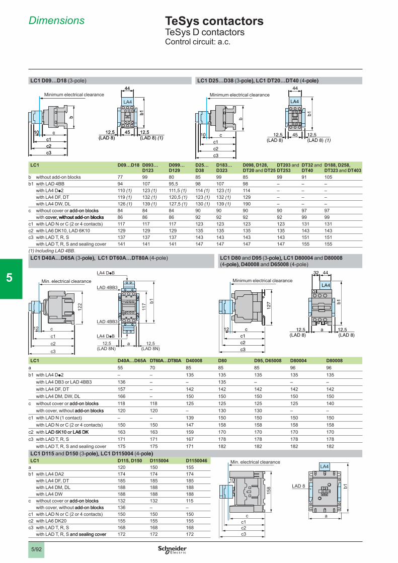
LC1 D09…D18 (3-pole) LC1 D25…D38 (3-pole),-pole),), LC1 DT20…DT40 (4-pole)-pole))
LC1 D09…D18 D093… D123
D099… D129
D25… D38
D183… D323
D098, D128,DT20 and DT25
DT203 and DT253
DT32 and�DT40
D188, D258, DT323 and DT403
b without add-on blocks 77 99 80 85 99 85 99 91 105b1 with LAD 4BB 94 107 95,5 98 107 98 – – –
with LA4 Dp2 110�(1) 123 (1) 111,5 (1) 114�(1) 123 (1) 114 – – –with LA4 DF, DT 119�(1) 132 (1) 120,5 (1) 123 (1) 132 (1) 129 – – –with LA4 DW, DL 126 (1) 139 (1) 127,5 (1) 130 (1) 139 (1) 190 – – –
c without cover or add-on blocksadd-on blocks 84 84 84 90 90 90 90 97 97with cover, without add-on blockscover, without add-on blocks, without add-on blockswithout add-on blocks 86 86 86 92 92 92 92 99 99
c1 with LAD N or C (2 or 4 contacts) 117 117 117 123 123 123 123 131 131c2 with LA6 DK10, LAD 6K10 129 129 129 135 135 135 135 143 143c3 with LAD T, R, S 137 137 137 143 143 143 143 151 151
with LAD T, R, S and sealing cover 141 141 141 147 147 147 147 155 155(1) Including LAD 4BB.LC1 D40A…D65A (3-pole),-pole),), LC1 DT60A…DT80A (4-pole) LC1 D80 and D95 (3-pole),-pole),), LC1 D80004�and�D80008
(4-pole),-pole),), D40008�and�D65008 (4-pole)
LAD 4BB3
117
122
a(LAD 8N) (LAD 8N)
12,5c1c2c3
LA4 DpB
LA4 DpB
LAD 4BB3
b1
12 c
12,5
Min. electrical clearance
LC1 D40A…D65A DT60A…DT80A D40008 D80 D95, D65008 D80004 D80008a 55 70 85 85 85 96 96b1 with LA4 Dp2 – – 135 135 135 135 135
with LA4 DB3 or LAD 4BB3 136 – – 135 – – –with LA4 DF, DT 157 – 142 142 142 142 142with LA4 DM, DW, DL 166 – 150 150 150 150 150
c without cover or add-on blocksadd-on blocks 118 118 125 125 125 125 140with cover, without add-on blocksadd-on blocks 120 120 – 130 130 – –
c1 with LAD N (1 contact) – – 139 150 150 150 150with LAD N or C (2 or 4 contacts) 150 150 147 158 158 158 158
c2 with LAD 6K10 or LA6 DKLAD 6K10 or LA6 DKLA6 DK 163 163 159 170 170 170 170c3 with LAD T, R, S 171 171 167 178 178 178 178
with LAD T, R, S and sealing cover 175 175 171 182 182 182 182LC1 D115 and D150 (3-pole),-pole),), LC1 D115004 (4-pole)-pole))LC1 D115, D150 D115004 D1150046
a 120 150 155b1 with LA4 DA2 174 174 174
with LA4 DF, DT 185 185 185with LA4 DM, DL 188 188 188with LA4 DW 188 188 188
c without cover or add-on blocksadd-on blocks 132 132 115with cover, without add-on blocksadd-on blocks 136 – –
c1 with LAD N or C (2 or 4 contacts) 150 150 150c2 with LA6 DK20 155 155 155c3 with LAD T, R, S 168 168 168
with LAD T, R, S and sealing coverand sealing cover 172 172 172
(LAD 8) (LAD 8)�(1)
b
c10c1c2c3
45 12,512,5
b1
44
LA4
(LAD 8) (LAD 8)�(1)
b
c10c1c2c3
45 12,512,5
b1
44
LA4
(LAD 8)
b
45 12,5(LAD 8) (1)
12,5
b1
44
LA4
c10
c1c2c3
Minimum electrical clearance
(LAD 8)
b
45 12,5(LAD 8) (1)
12,5
b1
44
LA4
c10
c1c2c3
Minimum electrical clearance
12,5(LAD 8) (LAD 8)
127 b1
a 12,5
4432
LA4
c12c1c2c3
Minimum electrical clearance
12,5(LAD 8) (LAD 8)
127 b1
a 12,5
4432
LA4
c12c1c2c3
Minimum electrical clearance
158
c ac1c2c3
b1LAD 8
LA4
10
Min. electrical clearance
158
c ac1c2c3
b1LAD 8
LA4
10
Min. electrical clearance
Minimum electrical clearance
TeSys contactorsTeSys D contactorsControl circuit: a.c.
Dimensions
1
2
3
4
5
6
7
8
9
10
5/93
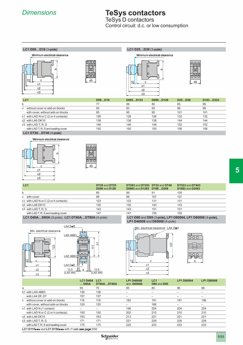
LC1 D09…D18 (3-pole)-pole)) LC1 D25…D38 (3-pole)-pole))
LC1 D09…D18 D093…D123 D099…D129 D25…D38 D183…D323b 77 99 80 85 99c without cover or add-on blocks 93 93 93 99 99
with cover, without add-on blocks 95 95 95 101 101c1 with LAD N or C (2 or 4 contacts) 126 126 126 132 132c2 with LA6 DK10 138 138 138 144 144c3 with LAD T, R, S 146 146 146 152 152
with LAD T, R, S and sealing cover 150 150 150 156 156LC1 DT20…DT40 (4-pole)-pole))
LC1 DT20 and DT25 D098 and D128
DT203 and DT253 D0983 and D1283
DT32 and DT40 D188…D258
DT323 and DT403 D1883 and D2583
b 85 99 91 105c with cover 99 99 107 107c1 with LAD N or C (2 or 4 contacts) 123 123 131 131c2 with LA6 DK10 135 135 143 143c3 with LAD T, R, S 143 143 151 151
with LAD T, R, S and sealing cover 147 147 155 155LC1 D40A…D65A (3-pole), LC1 DT60A…DT80A (4-pole) LC1 D80 and D95 (3-pole),-pole),), LP1 D80004, LP1 D80008 (4-pole),-pole),), �
LP1 D40008 and D65008 (4-pole)
LAD 4BB3
117
122
a(LAD 8N) (LAD 8N)
12,5c1c2c3
LA4 DpB
LA4 DpB
LAD 4BB3
b1
12 c
12,5
LC1 D40A… D65A
LC1DT60A…DT80A
LP1 D40008and D65008
LC1D80 and D95
LP1 D80004 LP1 D80008
a 55 70 85 85 96 96b1 with LAD 4BB3 136 136 – – – –
with LA4 DF, DT 157 157 – – – –c without cover or add-on blocks 118 118 182 181 181 196
with cover, without add-on blocks 120 120 – 186 – –c1 with LAD N (1 contact) – – 196 204 204 204
with LAD N or C (2 or 4 contacts) 150 150 202 210 210 210c2 with LA6 DK10 163 163 213 221 221 221c3 with LAD T, R, S 171 171 221 229 229 229
with LAD T, R, S and sealing cover 175 175 225 233 233 233LC1 D115ppp and�LC1 D150ppp with c coil: see pagecoil: see page: see page 5/92
b
c10c1c2c3
45
Minimum electrical clearanceb
c10c1c2c3
45
Minimum electrical clearance
c
b
10c1c2c3
45
Minimum electrical clearance
c
b
10c1c2c3
45
Minimum electrical clearance
c
b
10c1c2c3
45
Minimum electrical clearance
c
b
10c1c2c3
45
Minimum electrical clearance
ac12c1c2c3
127
Min. electrical clearance
ac12c1c2c3
127
Min. electrical clearanceMin. electrical clearance
TeSys contactorsTeSys D contactorsControl circuit: d.c. or low consumption
Dimensions pg3
1
2
3
4
5
6
7
8
9
10
5/94
TeSys contactorsTeSys D contactors
Mounting
Selection:pages 5/194�to�5/225
Characteristics:�pages 5/50�to�5/55
References:�pages 5/62�to�5/67
Schemes:�pages 5/96�and�5/97
Selection:pages 5/194�to�5/225
Characteristics:�pages 5/50�to�5/55
References:�pages 5/62�to�5/67
Schemes:�pages 5/96�and�5/97
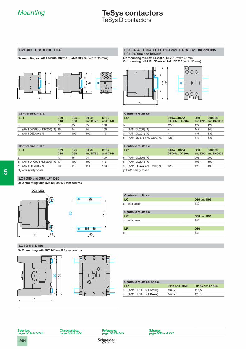
LC1 D09…D38, DT20…DT40 LC1 D40A…D65A, LC1 DT60A and DT80A, LC1 D80 and D95,LC1 D40008 and D65008
On mounting rail AM1 DP200, DR200 or AM1 DE200 (width 35 mm) On mounting rail AM1 DL200 or DL201 (width 75 mm)On mounting rail AM1 EDppp or AM1 DE200 (width 35 mm)
Control circuit: a.c. Control circuit: a.c.LC1 D09…
D18D25…D38
DT20 and DT25
DT32 and DT40
LC1 D40A…D65ADT60A…DT80A
D80and D95
D40008and D65008
b 77 85 85 100 b 122 127 127c (AM1 DP200 or DR200) (1) 88 94 94 109 c (AM1 DL200) (1) – 147 143c (AM1 DE200) (1) 96 102 102 117 c (AM1 DL201) (1) – 137 133
c (AM1 EDppp or DE200) (1) 128 137 133
Control circuit: d.c. Control circuit: d.c.LC1 D09…
D18D25…D38
DT20 and DT25
DT32 and DT40
LC1 D40A…D65ADT60A…DT80A
D80and D95
D40008and D65008
b 77 85 94 109 c (AM1 DL200) (1) – 205 200c (AM1 DP200 or DR200) (1) 97 103 103 118 c (AM1 DL201) (1) – 195 190c (AM1 DE200) (1) 105 110 111 1236 c (AM1 EDppp or DE200) (1) 128 128 190(1) with safety cover. (1) with safety cover.
LC1 D80 and D95, LP1 D80On 2 mounting rails DZ5 MB on 120 mm centres
Control circuit: a.c.LC1 D80 and D95
c with cover 130
Control circuit: d.c.LC1 D80 and D95
c with cover 186
LP1 D80c 181
LC1 D115, D150On 2 mounting rails DZ5 MB on 120 mm centres
100
==
158
c
Control circuit: a.c. or d.c.LC1 D115 and D150 D1156 and D1506
c (AM1 DP200 or DR200) 134,5 117,5c (AM1 DE200 or EDppp) 142,5 125,5
c
=
b
=
c
=
b
=
c
=
b
=
c
=
b
=
==
c
b
==
c
b
110
120
40c 15
DZ5 ME5
110
120
40c 15
DZ5 ME5
1
2
3
4
5
6
7
8
9
10
5/95
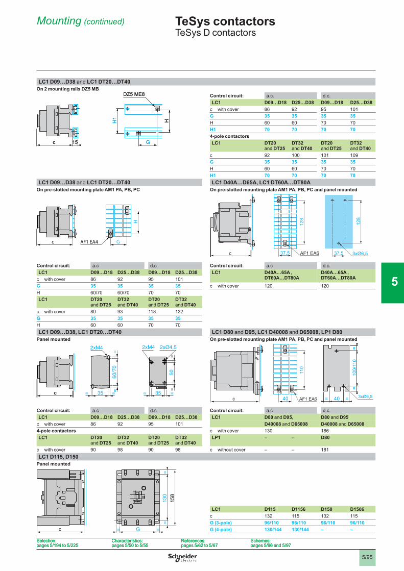
LC1 D09…D38 and LC1 DT20…DT40On 2 mounting rails DZ5 MB
Control circuit: a��c�� d��c��LC1 D09…D18 D25…D38 D09…D18 D25…D38
c with cover 86 92 95 101G 35 35 35 35H 60 60 70 70H1 70 70 70 704-pole contactorsLC1 DT20
and DT25DT32 and DT40
DT20 and DT25
DT32 and DT40
c 92 100 101 109G 35 35 35 35H 60 60 70 70H1 70 70 70 70
LC1 D09…D38 and LC1 DT20…DT40 LC1 D40A…D65A, LC1 DT60A…DT80AOn pre-slotted mounting plate AM1 PA, PB, PC On pre-slotted mounting plate AM1 PA, PB, PC and panel mounted
Control circuit: a��c d��c Control circuit: a��c d��c��LC1 D09…D18 D25…D38 D09…D18 D25…D38 LC1 D40A…65A ,
DT60A…DT80AD40A…65A , DT60A…DT80Ac with cover 86 92 95 101
G 35 35 35 35 c with cover 120 120H 60/70 60/70 70 70LC1 DT20
and DT25DT32 and DT40
DT20 and DT25
DT32 and DT40
c with cover 80 93 118 132G 35 35 35 35H 60 60 70 70LC1 D09…D38, LC1 DT20…DT40 LC1 D80 and D95, LC1 D40008 and D65008, LP1 D80
Panel mounted On pre-slotted mounting plate AM1 PA, PB, PC and panel mounted�
Control circuit: a��c d��c Control circuit: a��c d��c��LC1 D09…D18 D25…D38 D09…D18 D25…D38 LC1 D80 and D95, D80 and D95
c with cover 86 92 95 101 D40008 and D65008 D40008 and D650084-pole contactors c with cover 130 186LC1 DT20
and DT25DT32 and DT40
DT20 and DT25
DT32 and DT40
LP1 – – D80
c with cover 90 98 90 98 c without cover – – 181LC1 D115, D150
Panel mounted
LC1 D115 D1156 D150 D1506c 132 115 132 115G (3-pole) 96/110 96/110 96/110 96/110G (4-pole) 130/144 130/144 – –
c 15
HH1
DZ5 ME8
Gc 15
HH1
DZ5 ME8
GH
AF1 EA4 Gc
H
AF1 EA4 Gc
50
2xM4
==
60/7
0=
=
35= =35= =
2xØ4,52xM4
c
50
2xM4
==
60/7
0=
=
35= =35= =
2xØ4,52xM4
c
130
==
158
c G= =
130
==
158
c G= =
TeSys contactorsTeSys D contactors
Mounting (continued)
128
37,5 AF1�EA6c 3xØ6,5
128
37,5
AF1�EA640
110
c 40= =
100/
110
==
3xØ6,5
Selection:pages 5/194�to�5/225
Characteristics:�pages 5/50�to�5/55
References:�pages 5/62�to�5/67
Schemes:�pages 5/96�and�5/97
Selection:pages 5/194�to�5/225
Characteristics:�pages 5/50�to�5/55
References:�pages 5/62�to�5/67
Schemes:�pages 5/96�and�5/97
1
2
3
4
5
6
7
8
9
10
5/96
Schemes
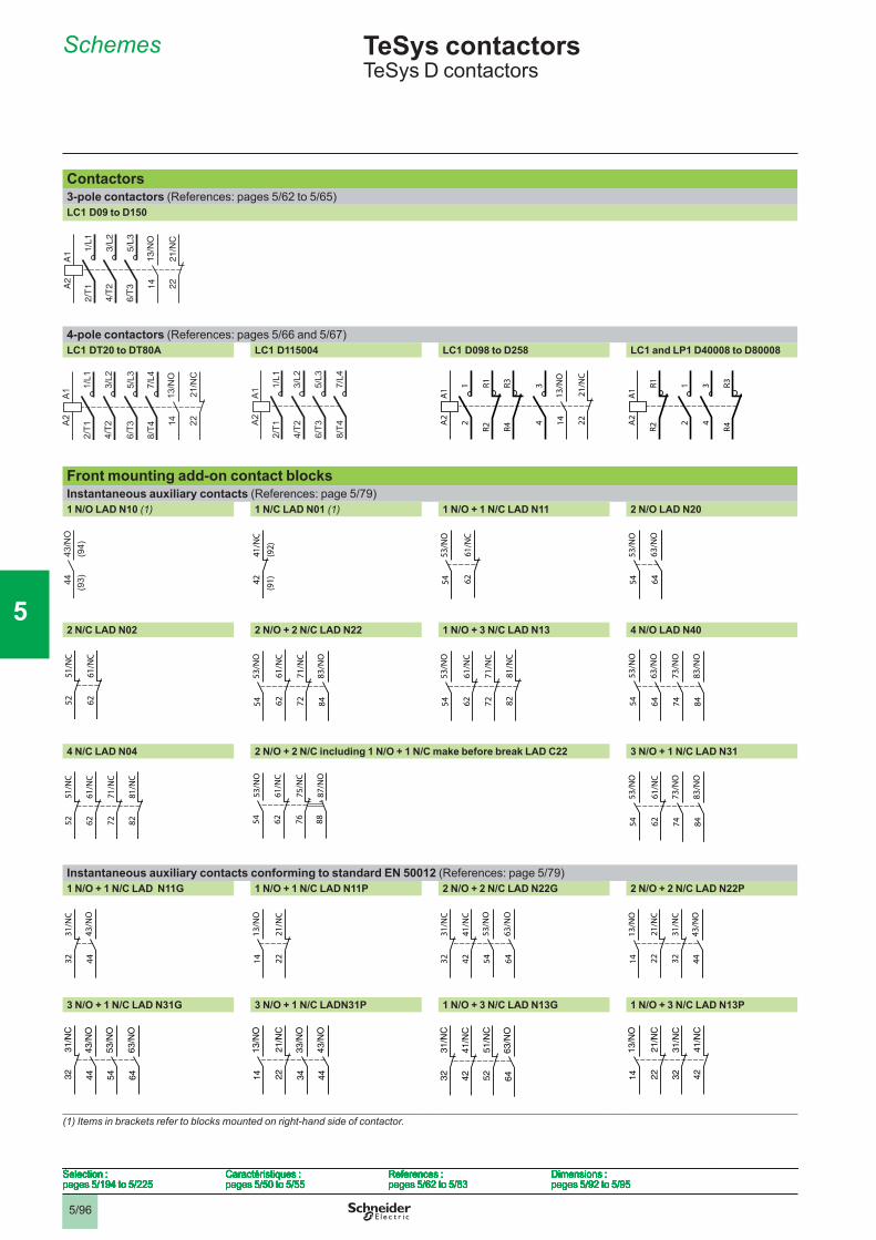
Contactors3-pole contactors (References: pages 5/62�to�5/65)LC1 D09 to D150
4-pole contactors (References: pages 5/66 and 5/67)LC1 DT20 to DT80A LC1 D115004 LC1 D098 to D258 LC1 and LP1 D40008 to D80008
�
Front mounting add-on contact blocksInstantaneous auxiliary contacts (References: page 5/79)1 N/O LAD N10 (1) 1 N/C LAD N01 (1) 1 N/O + 1 N/C LAD N11 2 N/O LAD N20
2 N/C LAD N02 2 N/O + 2 N/C LAD N22 1 N/O + 3 N/C LAD N13 4 N/O LAD N40
4 N/C LAD N04 2 N/O + 2 N/C including 1 N/O + 1 N/C make before break LAD C22 3 N/O + 1 N/C LAD N31
Instantaneous auxiliary contacts conforming to standard EN 50012 (References: page 5/79)1 N/O + 1 N/C LAD N11G 1 N/O + 1 N/C LAD N11P 2 N/O + 2 N/C LAD N22G 2 N/O + 2 N/C LAD N22P
3 N/O + 1 N/C LAD N31G 3 N/O + 1 N/C LADN31P 1 N/O + 3 N/C LAD N13G 1 N/O + 3 N/C LAD N13P
(1) Items in brackets refer to blocks mounted on right-hand side of contactor.����
A1
A2
13/N
O14
1/L1
2/T
1
3/L2
5/L3
2221
/NC
4/T
2
6/T
3
A1
A2
13/N
O14
1/L1
2/T
1
3/L2
5/L3
2221
/NC
4/T
2
6/T
3
A1
A2
1/L1
2/T1
3/L2
4/T2
5/L3
6/T3
7/L4
8/T4
A1
A2
1/L1
2/T1
3/L2
4/T2
5/L3
6/T3
7/L4
8/T4
A1
A2
12
R1R2
R3R4
34
13/N
O14 22
21/N
C
A1
A2
12
R1R2
R3R4
34
13/N
O14 22
21/N
C
A1
A2
R1R2
R3R4
12
34
A1
A2
R1R2
R3R4
12
34
4443
/NO
(94)
(93)44
43/N
O(9
4)(9
3) 4241
/NC
(91)
(92)
4241
/NC
(91)
(92)
53/N
O54 62
61/N
C
53/N
O54 62
61/N
C
63/N
O64
53/N
O54
63/N
O64
53/N
O54
5251
/NC
6261
/NC
5251
/NC
6261
/NC
7271
/NC
6261
/NC
83/N
O84
53/N
O54 72
71/N
C
6261
/NC
83/N
O84
53/N
O54 72
71/N
C
6261
/NC
53/N
O54 82
81/N
C
7271
/NC
6261
/NC
53/N
O54 82
81/N
C
83/N
O84
73/N
O74
63/N
O64
53/N
O54
83/N
O84
73/N
O74
63/N
O64
53/N
O54
5251
/NC
6261
/NC
7271
/NC
8281
/NC
5251
/NC
6261
/NC
7271
/NC
8281
/NC
53/N
O54
61/N
C62
87/N
O88
75/N
C76
53/N
O54
61/N
C62
87/N
O88
75/N
C76 62
61/N
C
83/N
O84
73/N
O74
53/N
O54 62
61/N
C
83/N
O84
73/N
O74
53/N
O54
3231
/NC
43/N
O4432
31/N
C
43/N
O44 22
21/N
C
13/N
O14 22
21/N
C
13/N
O14 32
31/N
C
4241
/NC
63/N
O64
53/N
O5432
31/N
C
4241
/NC
63/N
O64
53/N
O54 32
31/N
C
2221
/NC
43/N
O44
13/N
O14 32
31/N
C
2221
/NC
43/N
O44
13/N
O14
3231
/NC
43/N
O44
63/N
O64
53/N
O5432
31/N
C
43/N
O44
63/N
O64
53/N
O54 22
21/N
C
33/N
O34
13/N
O14
43/N
O4422
21/N
C
33/N
O34
13/N
O14
43/N
O44 42
41/N
C
3231
/NC
5251
/NC
63/N
O6442
41/N
C
3231
/NC
5251
/NC
63/N
O64 32
31/N
C
2221
/NC
13/N
O14 42
41/N
C
3231
/NC
2221
/NC
13/N
O14 42
41/N
C
Selection :pages 5/194�to�5/225
Caractéristiques :pages 5/50�to�5/55
References :pages 5/62�to�5/83
Dimensions :pages 5/92�to�5/95
Selection :pages 5/194�to�5/225
Caractéristiques :pages 5/50�to�5/55
References :pages 5/62�to�5/83
Dimensions :pages 5/92�to�5/95
Selection :pages 5/194�to�5/225
Caractéristiques :pages 5/50�to�5/55
References :pages 5/62�to�5/83
Dimensions :pages 5/92�to�5/95
Selection :pages 5/194�to�5/225
Caractéristiques :pages 5/50�to�5/55
References :pages 5/62�to�5/83
Dimensions :pages 5/92�to�5/95
Selection :pages 5/194�to�5/225
Caractéristiques :pages 5/50�to�5/55
References :pages 5/62�to�5/83
Dimensions :pages 5/92�to�5/95
Selection :pages 5/194�to�5/225
Caractéristiques :pages 5/50�to�5/55
References :pages 5/62�to�5/83
Dimensions :pages 5/92�to�5/95
Selection :pages 5/194�to�5/225
Caractéristiques :pages 5/50�to�5/55
References :pages 5/62�to�5/83
Dimensions :pages 5/92�to�5/95
Selection :pages 5/194�to�5/225
Caractéristiques :pages 5/50�to�5/55
References :pages 5/62�to�5/83
Dimensions :pages 5/92�to�5/95
TeSys contactors 5 TeSys D contactors�
1
2
3
4
5
6
7
8
9
10
5/97
Schemes (continued)
Selection :pages 5/194�to�5/225
Characteristics :pages 5/50�to�5/55
References :pages 5/62�to�5/83
Dimensions :pages 5/92�to�5/95
Selection :pages 5/194�to�5/225
Characteristics :pages 5/50�to�5/55
References :pages 5/62�to�5/83
Dimensions :pages 5/92�to�5/95
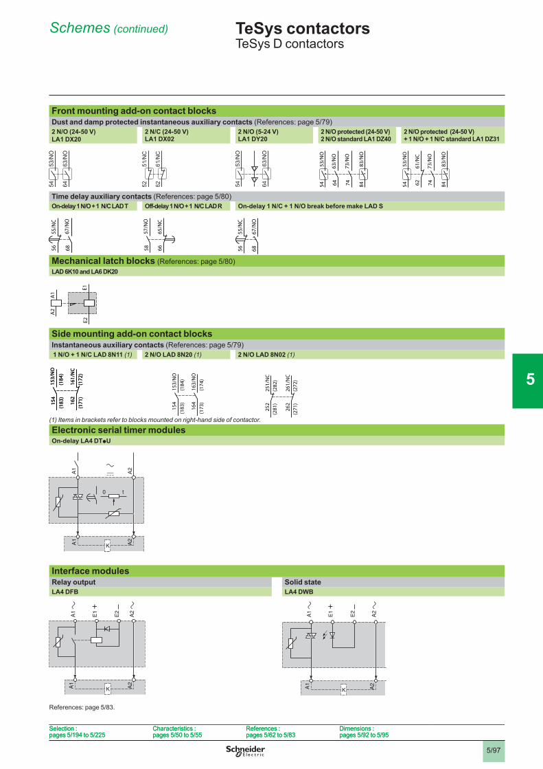
Front mounting add-on contact blocksDust and damp protected instantaneous auxiliary contacts (References: page 5/79)2 N/O (24-50 V) LA1 DX20
2 N/C (24-50 V) LA1 DX02
2 N/O (5-24 V) LA1 DY20
2 N/O protected (24-50 V) 2 N/O standard LA1 DZ40
2 N/O protected (24-50 V) + 1 N/O + 1 N/C standard LA1 DZ31
Time delay auxiliary contacts (References: page 5/80)On-delay 1 N/O + 1 N/C LAD T Off-delay 1 N/O + 1 N/C LAD R On-delay 1 N/C + 1 N/O break before make LAD S
Mechanical latch blocks (References: page 5/80)LAD 6K10 and LA6 DK20
Side mounting add-on contact blocksInstantaneous auxiliary contacts (References: page 5/79) 1 N/O + 1 N/C LAD 8N11 (1) 2 N/O LAD 8N20 (1) 2 N/O LAD 8N02 (1)
(1) Items in brackets refer to blocks mounted on right-hand side of contactor.
Electronic serial timer modulesOn-delay LA4 DTpU
Interface modulesRelay output Solid stateLA4 DFB LA4 DWB
References: page 5/83��
53/N
O54
83/N
O84
63/N
O64
73/N
O74
53/N
O54
83/N
O84
63/N
O64
73/N
O74 62
61/N
C
53/N
O54
83/N
O84
73/N
O7462
61/N
C
53/N
O54
83/N
O84
73/N
O74
55/N
C56
67/N
O68
55/N
C56
67/N
O68 66
65/N
C
57/N
O58 66
65/N
C
57/N
O58
67/N
O68
55/N
C56
67/N
O68
55/N
C56
A1
A2
E1E2
A1
A2
E1E2
162
161/
NC
(171
)(1
72)
153/
NO
154
(183
)(1
84)
162
161/
NC
(171
)(1
72)
153/
NO
154
(183
)(1
84)
TeSys contactors 5 TeSys D contactors
153/
NO
154
(184
)(1
83)
163/
NO
164
(174
)(1
73)
262
261/
NC
(271
)(2
72)
251/
NC
252
(281
)(2
82) 5
2
1
3
4
5
6
7
8
9
10
5/985/98
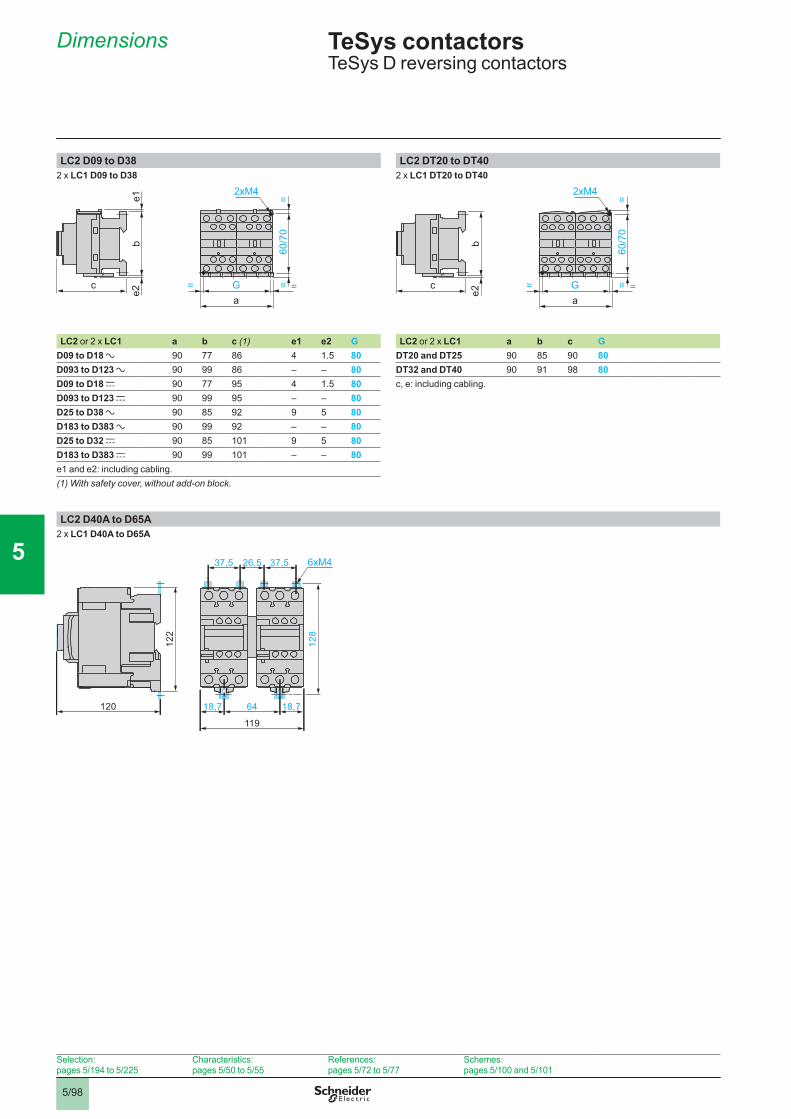
Dimensions TeSys contactors TeSys D reversing contactors
LC2 D09 to D38 LC2 DT20 to DT402 x LC1 D09 to D38 2 x LC1 DT20 to DT40
2xM4
Ga
= =60
/70
==c
be1
e2
2xM4
Ga
= =
60/7
0=
=c
be2
LC2 or 2 x LC1 a b c (1) e1 e2 G LC2 or 2 x LC1 a b c GD09 to D18 a 90 77 86 4 1��5 80 DT20 and DT25 90 85 90 80D093 to D123 a 90 99 86 – – 80 DT32 and DT40 90 91 98 80D09 to D18 c 90 77 95 4 1��5 80 c, e: including cabling.D093 to D123 c 90 99 95 – – 80D25 to D38 a 90 85 92 9 5 80D183 to D383 a 90 99 92 – – 80D25 to D32 c 90 85 101 9 5 80D183 to D383 c 90 99 101 – – 80e1�and e2: including cabling.(1) With safety cover, without add-on block.
LC2 D40A to D65A2 x LC1 D40A to D65A
122
128
120
119
6418,7 18,7
26,537,5 37,5 6xM4
Selection:pages 5/194�to�5/225
Characteristics:pages 5/50�to�5/55
References:pages 5/72 to 5/77
Schemes:pages 5/100�and�5/101
2
1
3
4
5
6
7
8
9
10
5/995/99
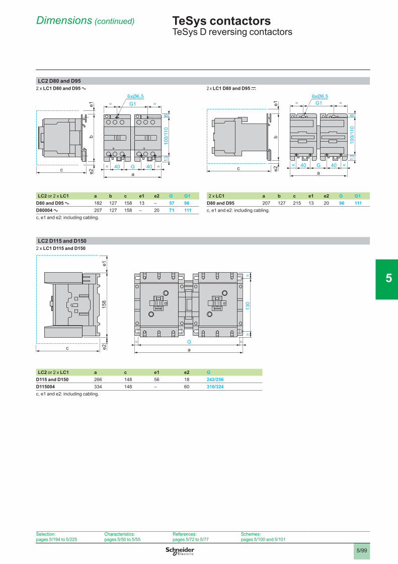
LC2 D80 and D952 x LC1 D80 and D95 a 2 x LC1 D80 and D95 c
c
be1
e2
G1= =6xØ6,5
40a
= =G 4010
0/11
08
13c
be1
e2
G1= =6xØ6,5
40a
= =G 40
100/
110
813
LC2 or�2 x LC1 a b c e1 e2 G G1 2 x LC1 a b c e1 e2 G G1D80 and D95 a 182 127 158 13 – 57 96 D80 and D95 207 127 215 13 20 96 111D80004 a 207 127 158 – 20 71 111 c, e1�and�e2: including cabling��c, e1�and�e2: including cabling��
LC2 D115 and D1502 x LC1 D115 and D150
158
e1e2c
Ga
= =
130
==
LC2 or�2 x LC1 a c e1 e2 GD115 and D150 266 148 56 18 242/256D115004 334 148 – 60 310/324c, e1�and�e2: including cabling��
Dimensions (continued) TeSys contactors TeSys D reversing contactors
Selection:pages 5/194�to�5/225
Characteristics:pages 5/50�to�5/55
References:pages 5/72 to 5/77
Schemes:pages 5/100�and�5/101
2
1
3
4
5
6
7
8
9
10
5/1005/100
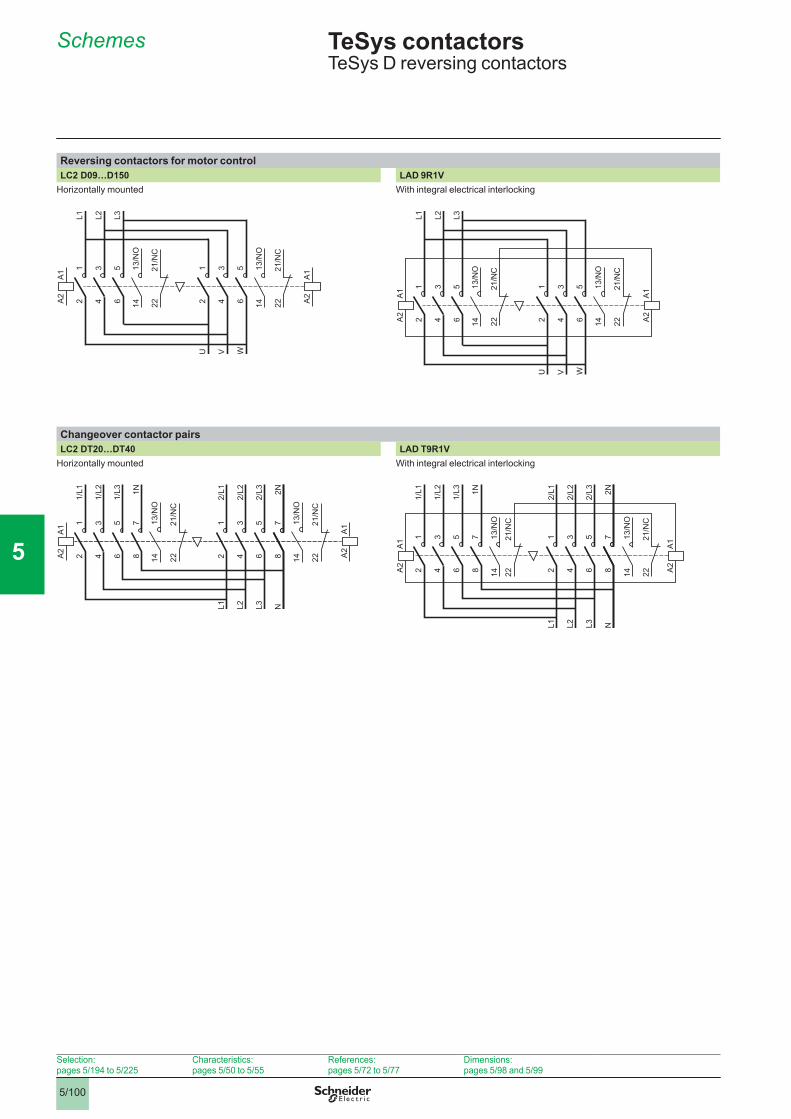
Schemes TeSys contactors TeSys D reversing contactors
Reversing contactors for motor controlLC2 D09…D150 LAD 9R1V
Horizontally mounted With integral electrical interlocking
14
A1
A2
12
34
56
L1 L2 L3
12
34
56
U V W
13/N
O
1413
/NO
A1
A2
2221
/NC
2221
/NC
14
A1
A2
12
34
56
L1 L2 L3
12
34
56
U V W
13/N
O
1413
/NO
A1
A2
2221
/NC
2221
/NC
Changeover contactor pairsLC2 DT20…DT40 LAD T9R1V
Horizontally mounted With integral electrical interlocking
A1
A2
12
34
56
1/L1
1/L2
1/L3
12
34
78
L1 L2 N
56
L3
78
1N
2/L1
2/L2
2/L3 2N
1413
/NO
2221
/NC
1413
/NO
A1
A2
2221
/NC
12
34
56
1/L1
1/L2
1/L3
12
34
78
L1 L2 N
56
L3
78
1N
2/L1
2/L2
2/L3 2N
14
A1
A2
13/N
O
1413
/NO
A1
A2
2221
/NC
2221
/NC
Selection:pages 5/194�to�5/225
Characteristics:pages 5/50�to�5/55
References:pages 5/72 to 5/77
Dimensions:pages 5/98�and�5/99
2
1
3
4
5
6
7
8
9
10
5/1015/101
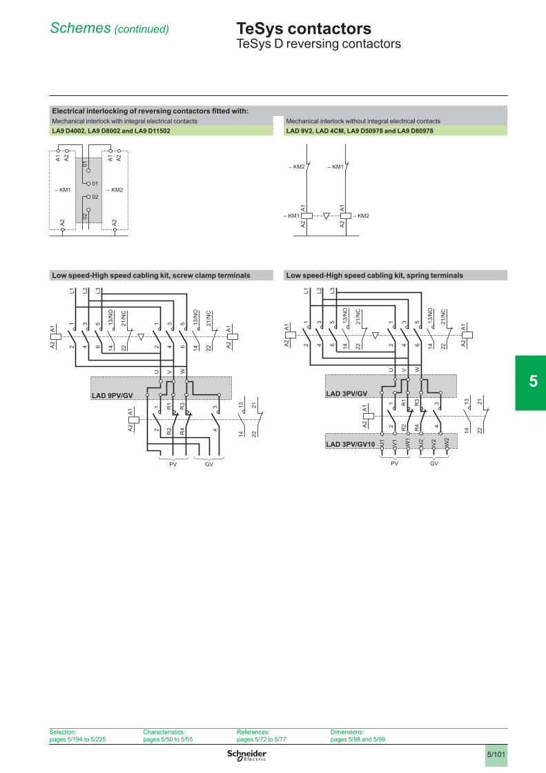
Schemes (continued) TeSys contactors TeSys D reversing contactors
Electrical interlocking of reversing contactors fitted with:Mechanical interlock with integral electrical contacts Mechanical interlock without integral electrical contactsLA9 D4002, LA9 D8002 and LA9 D11502 LAD 9V2, LAD 4CM, LA9 D50978 and LA9 D80978
0102
01
02
A1
A2
A2
A1
A2
A2
– KM2– KM1
A1
A2
– KM1
– KM2
A1
A2
– KM2
– KM1
Low speed-High speed cabling kit, screw clamp terminals Low speed-High speed cabling kit, spring terminals
14
A1
A2
12
34
56
12
34
L1 L2 L3
12
34
56
U V W
13/N
O
1413
/NO
A1
A2
A1
A2
2221
/NC
2221
/NC
1413
2221
PV GV
R1
R2
R3
R4
LAD 9PV/GV
14
A1
A2
12
34
56
12
34
L1 L2 L3
12
34
56
U V W
13/N
O
1413
/NO
A1
A2
A1
A2
2221
/NC
2221
/NC
PV GV
R1
R2
R3
R4
LAD 3PV/GV
U1
V1
W1
U2
V2
W2
LAD 3PV/GV10
1413
2221
Selection:pages 5/194�to�5/225
Characteristics:pages 5/50�to�5/55
References:pages 5/72 to 5/77
Dimensions:pages 5/98�and�5/99