Embed Size (px)
Citation preview

131
5
LC1 D50A
LC1 D65A
LC1 D80
LC1 D95
LC1 D115
LC1 D150
LC1 F185
LC1 F225
LC1 F26
LC1 F330
LC1 F40
LC1 F500
LC1 F630
LC1 F780
LC1 F800
LC1 BL
LC1 BM
LC1 BP
LC1 BR
300 390 480 570 630 830 1020 1230 1470 1800 2220 2760 3360 4260 3690 4320 5000 7500 9000
170 210 250 250 540 640 708 810 1020 1410 1830 2130 2760 2910 2910 4000 4800 5400 6600
SFlb 140 160 200 200 280 310 380 420 560 670 780 1100 1400 1600 1600 2250 3000 4500 5400
SFlb 120 148 170 170 250 280 350 400 500 600 700 950 1250 1400 1400 2000 2400 3750 5000
SFlb 100 132 145 145 215 240 300 330 400 500 600 750 950 1100 1100 1500 2000 3000 3600
SFlb 80 110 120 120 150 170 240 270 320 390 450 600 720 820 820 1000 1500 2000 2500
SFlb 70 90 100 100 125 145 170 190 230 290 350 500 660 710 710 750 1000 1500 1800
LCp D50A
LCp D65A
LCp D80
LCp D95
LC1 D115
LC1 D150
LC1 F185
LC1 F225
LC1 F265
LC1 F330
LC1 F400
LC1 F500
LC1 F630
LC1 F780
LC1 F800
LC1 BL
LC1 BM
LC1 BP
LC1 BR
5.5 7.5 7.5 9 9 11 18.5 22 28 33 40 45 55 63 63 90 110 150 200
11 11 15 15 18.5 22 33 40 51 59 75 80 100 110 110 160 160 220 250
11 11 15 15 18.5 22 37 45 55 63 80 90 100 110 110 160 160 250 280
11 15 15 15 18.5 22 37 45 59 63 80 100 110 132 132 160 200 250 315
15 15 22 22 30 37 45 55 63 75 90 110 132 150 150 180 200 250 355
15 18.5 25 25 30 45 63 75 90 110 129 140 160 185 185 200 250 315 450
5

132
TeSys contactors 5 For utilisation categories AC-2 or AC-4
Selection(continued) 5
Selection according to required electrical durability, in categories AC-2 or AC-4 (Ue y 440 V)
Control of 3-phase asynchronous squirrel cage motors (AC-4) or slip ring motors (AC-2) with breaking whilst motor stalled.
The current broken (Ic) in AC-2 is equal to 2.5 x Ie.
The current broken (Ic) in AC-4 is equal to 6 x Ie. (Ie = rated operational current of the motor).
Example:Asynchronous motor with P = 5.5 kW - Ue = 400 V - Ie = 11 A. Ic = 6 x Ie = 66 A
or asynchronous motor with P = 5.5 kW - Ue = 415 V - Ie = 11 A. Ic = 6 x Ie = 66 A.
200 000 operating cycles required.
The above selection curves show the contactor rating needed: LC1 D25.
(1) The dotted lines are only applicable to LC1, LP1 K12 contactors.
bbbb
Selection according to required electrical durability, use in category AC-4 (440 V < Ue y 690 V)
Control of 3-phase asynchronous squirrel cage motors with breaking whilst motor stalled
The current broken (Ic) in AC-2 is equal to 2.5 x Ie.
The current broken (Ic) in AC-4 is equal to 6 x Ie. (Ie = rated operational current of the motor).
5 6 7 8 9 10 20 30 36 40 50 54 8072 108 150 192 240 300 390 480 630 828 1000570
0,01
0,02
0,03
0,04
0,06
0,05
0,08
0,1
0,2
0,4
0,6
0,8
1
LC
1 D
09
LC
1 D
12
LC
1 D
18
LC
1 D
25
LC
1 D
32
et
D38
LC
1 D
40
A
LC
1 D
50
A
LC
1 D
65
A
LC
1 D
80
LC
1 D
95
LC
1 D
11
5
LC
1 D
15
0
LC
1,
LP
1,
LP
4 K
09
,K1
2
LC
1,
LP
1,
LP
4 K
06
(1)
Mill
ions o
f opera
ting c
ycle
s
Current broken in A
5 6 7 8 9 10 20 30 40 50 9070 105 121 210 250 300 400 500 640 800 1000540
0,01
0,02
0,03
0,04
0,06
0,05
0,080,07
0,1
0,2
0,4
0,6
0,8
1
LC
1 D
09
LC
1 D
12
LC
1 D
18
LC
1 D
25
LC
1 D
40A
LC
1 D
50A
LC
1 D
65A
LC
1 D
80
LC
1 D
95
LC
1 D
115
LC
1 D
150
150
LC
1 D
32, D
38
Mill
ions o
f opera
ting c
ycle
s
Current broken in A
Characteristics : page 138
References : pages 150 to 155
Dimensions, Schemes : pages 180 to 185
Characteristics : page 138
References : pages 150 to 155
Dimensions, Schemes : pages 180 to 185
133
TeSys contactors 5 For utilisation categories AC-2 or AC-4
Selection(continued) 5
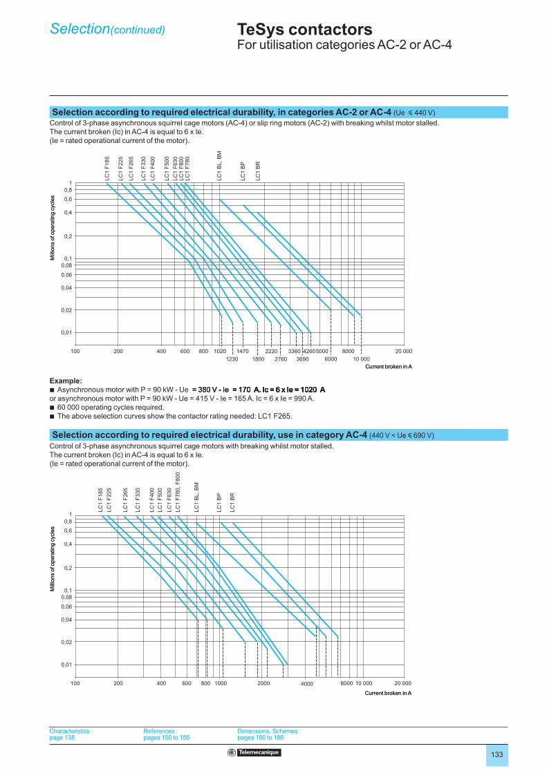
Selection according to required electrical durability, in categories AC-2 or AC-4 (Ue y 440 V)
Control of 3-phase asynchronous squirrel cage motors (AC-4) or slip ring motors (AC-2) with breaking whilst motor stalled.
The current broken (Ic) in AC-4 is equal to 6 x Ie.
(Ie = rated operational current of the motor).
Example:Asynchronous motor with P = 90 kW - Ue = 380 V - Ie = 170 A. Ic = 6 x Ie = 1020 A = 380 V - Ie = 170 A. Ic = 6 x Ie = 1020 A= 380 V - Ie = 170 A. Ic = 6 x Ie = 1020 A = 170 A. Ic = 6 x Ie = 1020 A= 170 A. Ic = 6 x Ie = 1020 A A. Ic = 6 x Ie = 1020 AA. Ic = 6 x Ie = 1020 A AA
or asynchronous motor with P = 90 kW - Ue = 415 V - Ie = 165 A. Ic = 6 x Ie = 990 A.
60 000 operating cycles required.
The above selection curves show the contactor rating needed: LC1 F265.
b
bb
Selection according to required electrical durability, use in category AC-4 (440 V < Ue y 690 V)
Control of 3-phase asynchronous squirrel cage motors with breaking whilst motor stalled.
The current broken (Ic) in AC-4 is equal to 6 x Ie.
(Ie = rated operational current of the motor).
6000 10 000
100 200 400 600 800 1020 1470 2220 3360 4260
369027601230 1800
5000 8000 20 000
1
0,8
0,6
0,4
0,2
0,1
0,08
0,06
0,04
0,02
0,01
LC
1 F
18
5
LC
1 F
22
5
LC
1 F
26
5
LC
1 F
33
0
LC
1 F
40
0
LC
1 F
50
0
LC
1 F
63
0L
C1
F8
00
LC
1 F
78
0
LC
1 B
L, B
M
LC
1 B
P
LC
1 B
R
Mill
ions o
f opera
ting c
ycle
s
Current broken in A
10 000100 200 400 600 800 1000 2000 4000 8000 20 000
1
0,8
0,6
0,4
0,2
0,1
0,08
0,06
0,04
0,02
0,01
LC
1 F
185
LC
1 F
225
LC
1 F
265
LC
1 F
330
LC
1 F
400
LC
1 F
500
LC
1 F
630
LC
1 F
780, F
800
LC
1 B
L, B
M
LC
1 B
P
LC
1 B
R
Mill
ions o
f opera
ting c
ycle
s
Current broken in A
10 000100 200 400 600 800 1000 2000 4000 8000 20 000
1
0,8
0,6
0,4
0,2
0,1
0,08
0,06
0,04
0,02
0,01
LC
1 F
185
LC
1 F
225
LC
1 F
265
LC
1 F
330
LC
1 F
400
LC
1 F
500
LC
1 F
630
LC
1 F
780, F
800
LC
1 B
L, B
M
LC
1 B
P
LC
1 B
R
Mill
ions o
f opera
ting c
ycle
s
Current broken in A
Characteristics : page 138
References : pages 150 to 155
Dimensions, Schemes : pages 180 to 185
Characteristics : page 138
References : pages 150 to 155
Dimensions, Schemes : pages 180 to 185
134
TeSys contactors 5 For utilisation categories DC-1 to DC-5
Selection 5
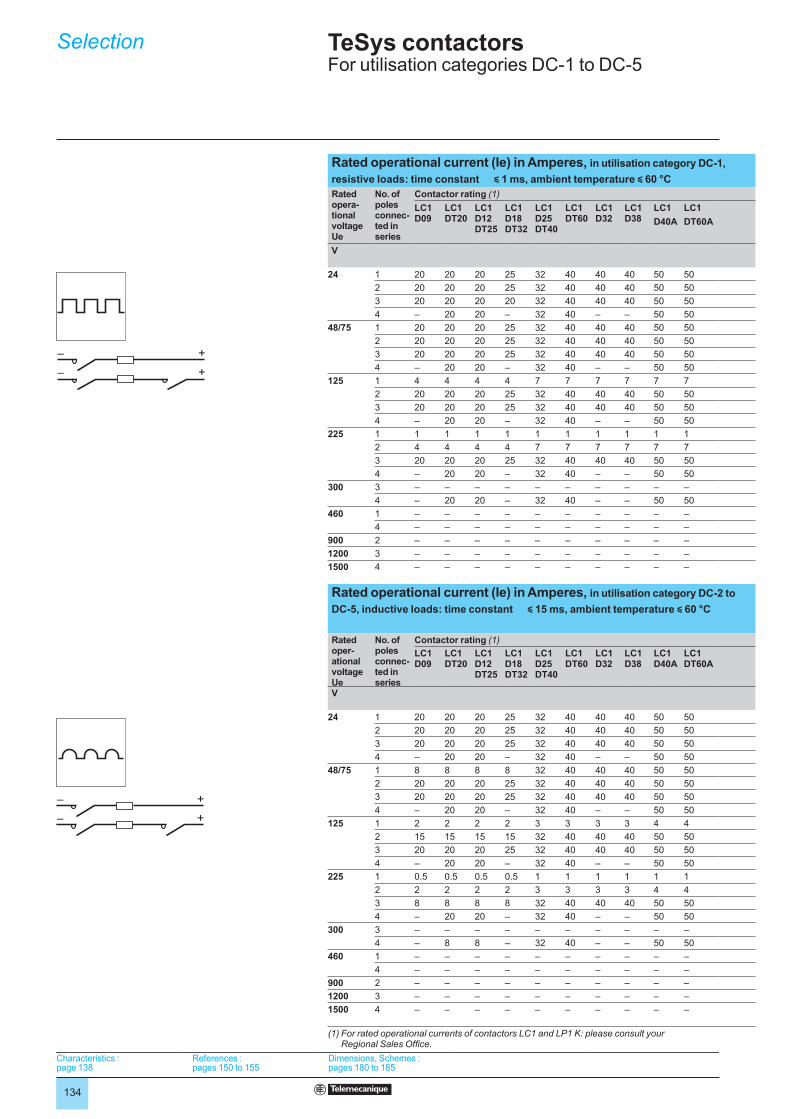
Rated operational current (Ie) in Amperes, in utilisation category DC-1,
resistive loads: time constant y 1 ms, ambient temperature y 60 °C
Rated opera-tional voltageUe
No. of poles connec-ted in series
Contactor rating (1)
LC1 D09
LC1DT20
LC1 D12DT25
LC1 D18DT32
LC1 D25DT40
LC1 DT60
LC1 D32
LC1 D38
LC1 LC1
D40A DT60A
V
24 1 20 20 20 25 32 40 40 40 50 50
2 20 20 20 25 32 40 40 40 50 50
3 20 20 20 20 32 40 40 40 50 50
4 – 20 20 – 32 40 – – 50 50
48/75 1 20 20 20 25 32 40 40 40 50 50
2 20 20 20 25 32 40 40 40 50 50
3 20 20 20 25 32 40 40 40 50 50
4 – 20 20 – 32 40 – – 50 50
125 1 4 4 4 4 7 7 7 7 7 7
2 20 20 20 25 32 40 40 40 50 50
3 20 20 20 25 32 40 40 40 50 50
4 – 20 20 – 32 40 – – 50 50
225 1 1 1 1 1 1 1 1 1 1 1
2 4 4 4 4 7 7 7 7 7 7
3 20 20 20 25 32 40 40 40 50 50
4 – 20 20 – 32 40 – – 50 50
300 3 – – – – – – – – – –
4 – 20 20 – 32 40 – – 50 50
460 1 – – – – – – – – – –
4 – – – – – – – – – –
900 2 – – – – – – – – – –
1200 3 – – – – – – – – – –
1500 4 – – – – – – – – – –
Rated operational current (Ie) in Amperes, in utilisation category DC-2 to
DC-5, inductive loads: time constant y 15 ms, ambient temperature y 60 °C
Rated oper-ational voltageUe
No. of poles connec-ted in series
Contactor rating (1)
LC1D09
LC1DT20
LC1D12DT25
LC1D18DT32
LC1 D25DT40
LC1 DT60
LC1 D32
LC1 D38
LC1D40A
LC1DT60A
V
24 1 20 20 20 25 32 40 40 40 50 50
2 20 20 20 25 32 40 40 40 50 50
3 20 20 20 25 32 40 40 40 50 50
4 – 20 20 – 32 40 – – 50 50
48/75 1 8 8 8 8 32 40 40 40 50 50
2 20 20 20 25 32 40 40 40 50 50
3 20 20 20 25 32 40 40 40 50 50
4 – 20 20 – 32 40 – – 50 50
125 1 2 2 2 2 3 3 3 3 4 4
2 15 15 15 15 32 40 40 40 50 50
3 20 20 20 25 32 40 40 40 50 50
4 – 20 20 – 32 40 – – 50 50
225 1 0.5 0.5 0.5 0.5 1 1 1 1 1 1
2 2 2 2 2 3 3 3 3 4 4
3 8 8 8 8 32 40 40 40 50 50
4 – 20 20 – 32 40 – – 50 50
300 3 – – – – – – – – – –
4 – 8 8 – 32 40 – – 50 50
460 1 – – – – – – – – – –
4 – – – – – – – – – –
900 2 – – – – – – – – – –
1200 3 – – – – – – – – – –
1500 4 – – – – – – – – – –
(1) For rated operational currents of contactors LC1 and LP1 K: please consult your Regional Sales Office.
– +
– +
– +
– +
– +
– +
– +
– +
Characteristics : page 138
References : pages 150 to 155
Dimensions, Schemes : pages 180 to 185
Characteristics : page 138
References : pages 150 to 155
Dimensions, Schemes : pages 180 to 185
Characteristics : page 138
References : pages 150 to 155
Dimensions, Schemes : pages 180 to 185
Characteristics : page 138
References : pages 150 to 155
Dimensions, Schemes : pages 180 to 185

135
5
LC1 D50A
LC1 D65A
LC1DT80A
LC1/ LP1D80
LC1 D95
LC1 D115
LC1 D150
LC1 F185
LC1 F225
LC1 F265
LC1 F330
LC1 F400
LC1 F500
LC1 F630
LC1 F780
LC1F800
LC1 BL
LC1 BM
LC1 BP
LC1 BR
65 65 65 100 100 200 200 240 260 300 360 430 580 850 1300 850 700 1100 1750 2400
65 65 65 100 100 200 200 240 260 300 360 430 580 850 1300 850 700 1100 1750 2400
65 65 65 100 100 200 200 240 260 300 360 430 580 850 1300 850 700 1100 1750 2400
– 65 65 100 – 200 – 240 260 300 360 430 580 850 1300 850 700 1100 1750 2400
65 65 65 100 100 200 200 240 260 300 360 430 580 850 1300 850 700 1100 1750 2400
65 65 65 100 100 200 200 240 260 300 360 430 580 850 1300 850 700 1100 1750 2400
65 65 65 100 100 200 200 240 260 300 360 430 580 850 1300 850 700 1100 1750 2400
– 65 65 100 – 200 – 240 260 300 360 430 580 850 1300 850 700 1100 1750 2400
7 7 7 12 12 200 200 210 230 270 320 380 520 760 1180 760 700 1100 1750 2400
65 65 65 100 100 200 200 210 230 270 320 380 520 760 1180 760 700 1100 1750 2400
65 65 65 100 100 200 200 240 260 300 360 430 580 850 1300 850 700 1100 1750 2400
– 65 65 100 – 200 – 240 260 300 360 430 580 850 1300 850 700 1100 1750 2400
1 1.5 1.5 1.5 1.5 10 10 – – – – – – – – – 700 1100 1750 2400
7 7 7 12 12 200 200 190 200 250 280 350 450 700 1000 700 700 1100 1750 2400
65 65 65 100 100 200 200 240 260 300 360 430 580 850 1300 850 700 1100 1750 2400
– 65 65 100 – 200 – 240 260 300 360 430 580 850 1300 850 700 1100 1750 2400
– – – – – 200 200 190 200 250 280 350 450 700 1000 700 700 1100 1750 2400
– 65 65 100 – 200 – 240 260 300 360 430 580 850 1000 850 700 1100 1750 2400
– – – – – – – – – – – – – – – – 700 1100 1750 2400
– – – – – 200 – 190 200 250 280 350 450 700 1000 700 700 1100 1750 2400
– – – – – – – – – – – – – – – – 700 1100 1750 2400
– – – – – – – – – – – – – – – – 700 1100 1750 2400
– – – – – – – – – – – – – – – – 700 1100 1750 2400
LC1 D50A
LC1 D65A
LC1DT80A
LC1 LP1 D80
LC1 D95
LC1 D115
LC1 D150
LC1 F185
LC1 F225
LC1 F265
LC1 F330
LC1 F400
LC1 F500
LC1 F630
LC1 F780
LC1 F800
LC1 BL
LC1 BM
LC1 BP
LC1 BR
65 65 65 100 100 200 200 240 260 300 360 430 580 850 1300 850 700 1100 1750 2400
65 65 65 100 100 200 200 240 260 300 360 430 580 850 1300 850 700 1100 1750 2400
65 65 65 100 100 200 200 240 260 300 360 430 580 850 1300 850 700 1100 1750 2400
– 65 65 100 – 200 – 240 260 300 360 430 580 850 1300 850 700 1100 1750 2400
65 65 65 100 100 200 200 240 260 300 360 430 580 850 1300 850 700 1100 1750 2400
65 65 65 100 100 200 200 240 260 300 360 430 580 850 1300 850 – – – –
65 65 65 100 100 200 200 240 260 300 360 430 580 850 1300 850 700 1100 1750 2400
– 65 65 100 – 200 – 240 260 300 360 430 580 850 1300 850 700 1100 1750 2400
4 4 4 5 5 200 200 – – – – – – – – – 700 1100 1750 2400
65 65 65 40 40 200 200 160 180 250 300 350 500 700 1000 700 700 1100 1750 2400
65 65 65 60 60 200 200 240 240 280 310 350 550 850 1000 850 700 1100 1750 2400
– 65 65 72 – 200 – 240 240 280 310 350 550 850 1000 850 700 1100 1750 2400
1 1.5 1.5 2 2 3 3 – – – – – – – – – 700 1100 1750 2400
4 4 4 5 5 200 200 140 160 220 280 310 480 680 900 680 700 1100 1750 2400
65 65 65 100 100 200 200 160 180 250 300 350 500 700 1000 700 700 1100 1750 2400
– 65 65 100 – 200 – 240 260 300 360 430 580 850 1300 850 700 1100 1750 2400
– – – – – 200 200 140 160 220 280 310 480 680 900 680 700 1100 1750 2400
– 65 65 100 – 200 – 240 260 300 360 430 580 850 1300 850 700 1100 1750 2400
– – – – – – – – – – – – – – – – 700 1100 1750 2400
– – – – – 200 – 140 160 220 280 310 480 680 800 680 700 1100 1750 2400
– – – – – – – – – – – – – – – – 700 1100 1750 2400
– – – – – – – – – – – – – – – – 700 1100 1750 2400
– – – – – – – – – – – – – – – – 700 1100 1750 2400
Characteristics : page 138
References : pages 150 to 155
Dimensions, Schemes : pages 180 to 185
Characteristics : page 138
References : pages 150 to 155
Dimensions, Schemes : pages 180 to 185
Characteristics : page 138
References : pages 150 to 155
Dimensions, Schemes : pages 180 to 185
Characteristics : page 138
References : pages 150 to 155
Dimensions, Schemes : pages 180 to 185
5

136
TeSys contactors 5 For utilisation categories DC-1 to DC-5
Selection 5
Selection according to required electrical durability, use in categories DC-1 to DC-5The criteria for contactor selection are:
the rated operational current Ie,
the rated operational voltage Ue,
the utilisation category and the time constant L/R,
the required electrical durability.
bbbb
Maximum operating rate (operating cycles)
The following limits must not be exceeded: 120 operating cycles/hour at rated operational current Ie.
Electrical durability
ExampleSeries wound motor - P = 1.5 kW - Ue = 200 V - Ie = 7.5 A. Utilisation: reversing, inching.
Utilisation category = DC-5.
Select contactor LC1 D25 or LP1 D25 with 3 poles in series.
The power broken is: Pc total = 2.5 x 200 x 7.5 = 3.75 kW.
The power broken per pole is: 1.25 kW.
The electrical durability read from the curve is u 106 operating cycles.
bbbbb
Use of poles in parallel
Electrical durability can be increased by using poles connected in parallel.
With N poles connected in parallel, the electrical durability becomes: electrical
durability read from the curves x N x 0.7.
Note; 1
When the poles are connected in parallel, the maximum operational currents
indicated on page 134 and 135 must not be exceeded.
Note: 2
Ensure that the connections are made in such a way as to equalise the currents in
each pole.
0,01
0,02
0,04
0,06
0,08
1
2
4
6
810
0,1
0,2
0,4
0,6
0,8
0,2 0,3 0,4 0,5 0,6
0,7
10,8
0,9
2 3 4 5 6 7 9
8 10 16
14 20 30
24 32 36
40 50 60 70 90
80
100
LC
1 D
09
LC
1,
LP
1 D
12
LC
1 D
18
LC
1,
LP
1 D
25
LC
1 D
32
,
LC
1 D
38
LC
1 D
40
A,
DT
60
A
LC
1 D
50
A
LC
1 D
65
A,
DT
80A
LC
1,
LP
1 D
80
LC
1 D
95
LC
1 D
11
5,
D1
50
Mill
ions o
f opera
ting c
ycle
s
Power broken per pole in kW
Characteristics : page 138
References : pages 150 to 155
Dimensions, Schemes : pages 180 to 185
Characteristics : page 138
References : pages 150 to 155
Dimensions, Schemes : pages 180 to 185
Characteristics : page 138
References : pages 150 to 155
Dimensions, Schemes : pages 180 to 185
Characteristics : page 138
References : pages 150 to 155
Dimensions, Schemes : pages 180 to 185
137
TeSys contactors 5 For utilisation categories DC-1 to DC-5
Selection(continued) 5
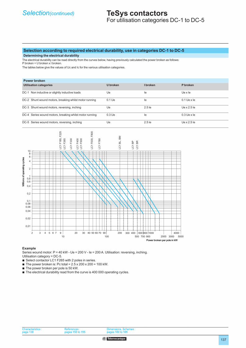
Selection according to required electrical durability, use in categories DC-1 to DC-5Determining the electrical durability
The electrical durability can be read directly from the curves below, having previously calculated the power broken as follows: P broken = U broken x l broken.
The tables below give the values of Uc and Ic for the various utilisation categories.
Power broken
Utilisation categories U broken I broken P broken
DC-1 Non inductive or slightly inductive loads Ue Ie Ue x Ie
DC-2 Shunt wound motors, breaking whilst motor running 0.1 Ue Ie 0.1 Ue x Ie
DC-3 Shunt wound motors, reversing, inching Ue 2.5 Ie Ue x 2.5 Ie
DC-4 Series wound motors, breaking whilst motor running 0.3 Ue Ie 0.3 Ue x Ie
DC-5 Series wound motors, reversing, inching Ue 2.5 Ie Ue x 2.5 Ie
ExampleSeries wound motor: P = 40 kW - Ue = 200 V - Ie = 200 A. Utilisation: reversing, inching.
Utilisation category = DC-5.
Select contactor LC1 F265 with 2 poles in series.
The power broken is: Pc total = 2.5 x 200 x 200 = 100 kW.
The power broken per pole is 50 kW.
The electrical durability read from the curve is 400 000 operating cycles.
bbbb
2 3 4 5 6 7 9
10
20 30 40 50 60 70
100
90 200 300 400
500
600
700
1000800
900 2000
4000
3000 5000
LC
1 F
185, F
225
LC
1 F
265
LC
1 F
330
LC
1 F
400
LC
1 F
500
LC
1 F
630, F
800
LC
1 F
780
LC
1 B
L, B
M
LC
1 B
P
LC
1 B
R
0,01
0,02
0,04
0,06
0,08
1
2
4
6
810
0,1
0,2
0,4
0,6
0,8
Mill
ions o
f opera
ting c
ycle
s
Power broken per pole in kW
Characteristics : page 138
References : pages 150 to 155
Dimensions, Schemes : pages 180 to 185
Characteristics : page 138
References : pages 150 to 155
Dimensions, Schemes : pages 180 to 185
Characteristics : page 138
References : pages 150 to 155
Dimensions, Schemes : pages 180 to 185
Characteristics : page 138
References : pages 150 to 155
Dimensions, Schemes : pages 180 to 185
138
Contactor type LC1 D09…D18DT20 and DT25
D25…D38DT32 and DT40
D40A…D65ADT60A and DT80A
D80…D95 D115 and D150
EnvironmentRated insulation voltage (Ui) Conforming to IEC 60947-4-1,
overvoltage category III, degree of pollution: 3
V 690 1000
Conforming to UL, CSA V 600
Rated impulse withstand voltage (Uimp)
Conforming to IEC 60947 kV 6 8
Conforming to standards IEC/EN 60947-4-1, IEC/EN 60947-5-1, UL 508, CSA C22.2 n°14.
Product certifications UL, CSA. CCC, GL, DNV, RINA, BV, LROS (pending for contactors LC1 D40A to D65A)
Degree of protection (1)(front face only)
Conforming to VDE 0106 and IEC 60529
Power circuit connections Protection against direct finger contact IP 2X
Coil connection Protection against direct finger contact IP 2X
Protective treatment Conforming to IEC 60068-2-30 “TH”
Ambient air temperature around the device
Storage °C - 60…+ 80
Operation °C - 5…+ 60
Permissible °C - 40…+ 70, for operation at Uc
Maximum operating altitude Without derating m 3000
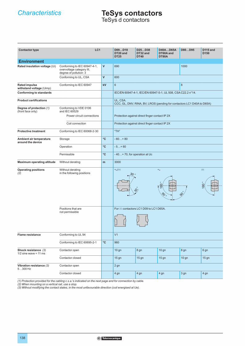
Operating positions (2)
Without derating in the following positions
a/c a c
30 °
30 °
90 ° 90 °
18
0 °
18
0 °
Positions that are not permissible
For c contactors LC1 D09 to LC1 D65A.
Flame resistance Conforming to UL 94 V1
Conforming to IEC 60695-2-1 °C 960
Shock resistance (3) 1/2 sine wave = 11 ms
Contactor open 10 gn 8 gn 10 gn 8 gn 6 gn
Contactor closed 15 gn 15 gn 15 gn 10 gn 15 gn
Vibration resistance (3) 5…300 Hz
Contactor open 2 gn
Contactor closed 4 gn 4 gn 4 gn 3 gn 4 gn
(1) Protection provided for the cabling c.s.a.'s indicated on the next page and for connection by cable.(2) When mounting on a vertical rail, use a stop.(3) Without modifying the contact states, in the most unfavourable direction (coil energised at Ue).
Characteristics TeSys contactorsTeSys d contactors
139
Contactor type LC1 D09 and D12 DT20 and DT25
D18(3P)
D25 (3P)
D32 D38 D18 and D25 (4P)DT32 and DT40
D40A to D65A DT60A and DT80A (1)
D80 and D95
D115 and D150
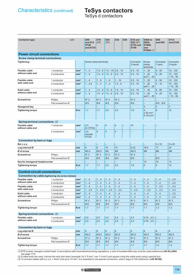
Power circuit connectionsScrew clamp terminal connections
Tightening Screw clamp terminals Connector2 inputs
Screw clamp terminals
Connector1 input
Connector2 inputs
Flexible cablewithout cable end
1 conductor mm2 1…4 1.5…6 1.5…10 2.5…10 2.5…10 1…35 4…50 10…120
2 conductors mm2 1…4 1.5…6 1.5…6 2.5…10 2.5…10 1…25and 1…35
4…25 10…120 + 10…50
Flexible cablewith cable end
1 conductor mm2 1…4 1…6 1…6 1…10 2.5…10 1…35 4…50 10…120
2 conductors mm2 1…2.5 1…4 1…4 1.5…6 2.5…10 1…25and 1…35
4…16 10…120 + 10…50
Solid cablewithout cable end
1 conductor mm2 1…4 1.5…6 1.5…6 1.5…10 2.5…16 1…35 4…50 10…120
2 conductors mm2 1…4 1.5…6 1.5…6 2.5…10 2.5…16 1…25and 1…35
4…25 10…120 + 10…50
Screwdriver Philips N° 2 N° 2 N° 2 N° 2 N° 2 – – –
Flat screwdriver Ø Ø 6 Ø 6 Ø 6 Ø 6 Ø 6 – Ø 6…Ø 8 –
Hexagonal key – – – – – 4 4 4
Tightening torque N.m 1.7 1.7 2.5 2.5 1.8 5: y 25 mm2
8: 35 mm2
9 12
Spring terminal connections (2)
Flexible cablewithout cable end
1 conductor mm2 2.5 (4: DT25)
4 4 4 – 10 – –
2 conductors mm2 2.5 (except DT25)
4 4 4 – – – –
Connection by bars or lugs
Bar c.s.a. – – – – – – 3 x 16 5 x 25
Lug external Ø mm 8 8 10 10 8 (3) 16.5 17 25
Ø of screw mm M3.5 M3.5 M4 M4 M3.5 M6 M6 M8
Screwdriver Philips N° 2 N° 2 N° 2 N° 2 N° 2 – – –
Flat screwdriver Ø Ø 6 Ø 6 Ø 6 Ø 6 Ø 6 – Ø 8 –
Key for hexagonal headed screw – – – – – 10 10 13
Tightening torque N.m 1.7 1.7 2.5 2.5 1.8 6 9 12
Control circuit connectionsConnection by cable (tightening via screw clamps)
Flexible cable without cable end
1 conductor mm2 1…4 1…4 1…4 1…4 1…4 1…4 1…4 1…2.5
2 conductors mm2 1…4 1…4 1…4 1…4 1…4 1…4 1…4 1…2.5
Flexible cable with cable end
1 conductor mm2 1…4 1…4 1…4 1…4 1…4 1…4 1…2.5 1…2.5
2 conductors mm2 1…2.5 1…2.5 1…2.5 1…2.5 1…2.5 1…2.5 1…2.5 1…2.5
Solid cable without cable end
1 conductor mm2 1…4 1…4 1…4 1…4 1…4 1…4 1…4 1…2.5
2 conductors mm2 1…4 1…4 1…4 1…4 1…4 1…4 1…4 1…2.5
Screwdriver Philips N° 2 N° 2 N° 2 N° 2 N° 2 N° 2 N° 2 N° 2
Flat screwdriver Ø Ø 6 Ø 6 Ø 6 Ø 6 Ø 6 Ø 6 Ø 6 Ø 6
Tightening torque N.m 1.7 1.7 1.7 1.7 1.7 1.7 1.2 1.2
Spring terminal connections (2)
Flexible cable without cable end
1 conductor mm2 2.5 2.5 2.5 2.5 – 2.5 0.75…2.5 – –
2 conductors mm2 2.5 2.5 2.5 2.5 – 2.5 0.75…2.5 – –
Connection by bars or lugs
Lug external Ø mm 8 8 8 8 8 8 8 8
Ø of screw mm M3.5 M3.5 M3.5 M3.5 M3.5 M3.5 M3.5 M3.5
Screwdriver Philips N° 2 N° 2 N° 2 N° 2 N° 2 N° 2 N° 2 N° 2
Flat screwdriver Ø Ø 6 Ø 6 Ø 6 Ø 6 Ø 6 Ø 6 Ø 6 Ø 6
Tightening torque N.m 1.7 1.7 1.7 1.7 1.7 1.7 1.2 1.2
(1) BTR screws: hexagon socket head. In accordance with local electrical wiring regulations, a size 4 insulated Allen key must be used (reference LAD ALLEN4, see page 173).
(2) If cable ends are used, choose the next size down (example: for 2.5 mm2, use 1.5 mm2) and square crimp the cable ends using a special tool.(3) To connect cables with a c.s.a. > 4mm2 and up to 10 mm2, it is essential to use special connectors, sold in bags of 100 (reference: LAD 96180).
Characteristics (continued) TeSys contactorsTeSys d contactors
140
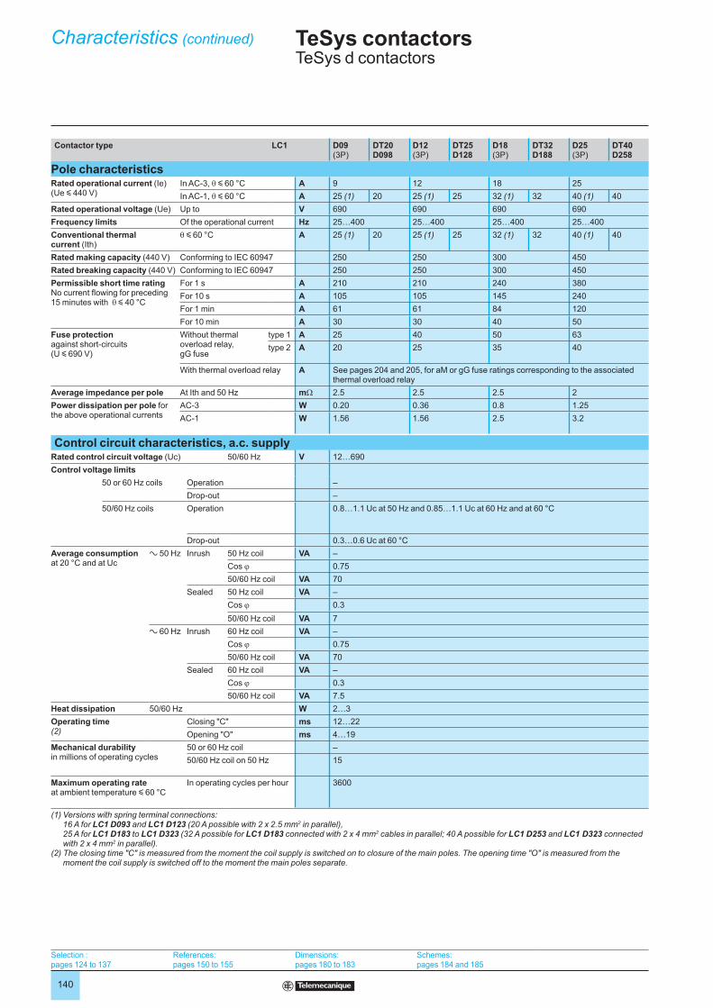
Contactor type LC1 D09(3P)
DT20D098
D12(3P)
DT25D128
D18(3P)
DT32D188
D25(3P)
DT40D258
Pole characteristicsRated operational current (Ie)(Ue y 440 V)
In AC-3, θ y 60 °C A 9 12 18 25
In AC-1, θ y 60 °C A 25 (1) 20 25 (1) 25 32 (1) 32 40 (1) 40
Rated operational voltage (Ue) Up to V 690 690 690 690
Frequency limits Of the operational current Hz 25…400 25…400 25…400 25…400
Conventional thermal current (Ith)
θ y 60 °C A 25 (1) 20 25 (1) 25 32 (1) 32 40 (1) 40
Rated making capacity (440 V) Conforming to IEC 60947 250 250 300 450
Rated breaking capacity (440 V) Conforming to IEC 60947 250 250 300 450
Permissible short time ratingNo current flowing for preceding 15 minutes with θ y 40 °C
For 1 s A 210 210 240 380
For 10 s A 105 105 145 240
For 1 min A 61 61 84 120
For 10 min A 30 30 40 50
Fuse protectionagainst short-circuits (U y 690 V)
Without thermal overload relay, gG fuse
type 1 A 25 40 50 63
type 2 A 20 25 35 40
With thermal overload relay A See pages 204 and 205, for aM or gG fuse ratings corresponding to the associated thermal overload relay
Average impedance per pole At Ith and 50 Hz mΩ 2.5 2.5 2.5 2
Power dissipation per pole for the above operational currents
AC-3 W 0.20 0.36 0.8 1.25
AC-1 W 1.56 1.56 2.5 3.2
Control circuit characteristics, a.c. supplyRated control circuit voltage (Uc) 50/60 Hz V 12…690
Control voltage limits
50 or 60 Hz coils Operation –
Drop-out –
50/60 Hz coils Operation 0.8…1.1 Uc at 50 Hz and 0.85…1.1 Uc at 60 Hz and at 60 °C
Drop-out 0.3…0.6 Uc at 60 °C
Average consumption at 20 °C and at Uc
a 50 Hz Inrush 50 Hz coil VA –
Cos ϕ 0.75
50/60 Hz coil VA 70
Sealed 50 Hz coil VA –
Cos ϕ 0.3
50/60 Hz coil VA 7
a 60 Hz Inrush 60 Hz coil VA –
Cos ϕ 0.75
50/60 Hz coil VA 70
Sealed 60 Hz coil VA –
Cos ϕ 0.3
50/60 Hz coil VA 7.5
Heat dissipation 50/60 Hz W 2…3
Operating time (2)
Closing "C" ms 12…22
Opening "O" ms 4…19
Mechanical durabilityin millions of operating cycles
50 or 60 Hz coil –
50/60 Hz coil on 50 Hz 15
Maximum operating rateat ambient temperature y 60 °C
In operating cycles per hour 3600
(1) Versions with spring terminal connections: 16 A for LC1 D093 and LC1 D123 (20 A possible with 2 x 2.5 mm2 in parallel), 25 A for LC1 D183 to LC1 D323 (32 A possible for LC1 D183 connected with 2 x 4 mm2 cables in parallel; 40 A possible for LC1 D253 and LC1 D323 connected with 2 x 4 mm2 in parallel).
(2) The closing time "C" is measured from the moment the coil supply is switched on to closure of the main poles. The opening time "O" is measured from the moment the coil supply is switched off to the moment the main poles separate.
Characteristics (continued) TeSys contactorsTeSys d contactors
Selection :pages 124 to 137
References:pages 150 to 155
Dimensions:pages 180 to 183
Schemes:pages 184 and 185
141
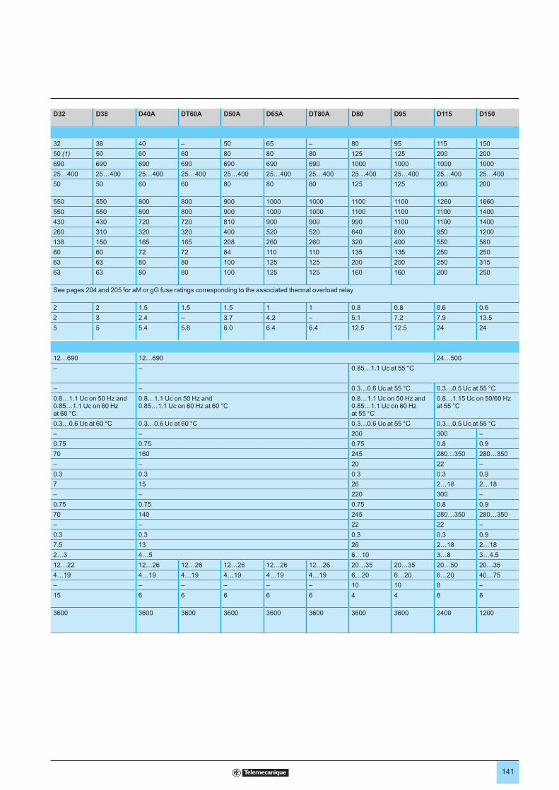
D32 D38 D40A DT60A D50A D65A DT80A D80 D95 D115 D150
32 38 40 – 50 65 – 80 95 115 150
50 (1) 50 60 60 80 80 80 125 125 200 200
690 690 690 690 690 690 690 1000 1000 1000 1000
25…400 25…400 25…400 25…400 25…400 25…400 25…400 25…400 25…400 25…400 25…400
50 50 60 60 80 80 80 125 125 200 200
550 550 800 800 900 1000 1000 1100 1100 1260 1660
550 550 800 800 900 1000 1000 1100 1100 1100 1400
430 430 720 720 810 900 900 990 1100 1100 1400
260 310 320 320 400 520 520 640 800 950 1200
138 150 165 165 208 260 260 320 400 550 580
60 60 72 72 84 110 110 135 135 250 250
63 63 80 80 100 125 125 200 200 250 315
63 63 80 80 100 125 125 160 160 200 250
See pages 204 and 205 for aM or gG fuse ratings corresponding to the associated thermal overload relay
2 2 1.5 1.5 1.5 1 1 0.8 0.8 0.6 0.6
2 3 2.4 – 3.7 4.2 – 5.1 7.2 7.9 13.5
5 5 5.4 5.8 6.0 6.4 6.4 12.5 12.5 24 24
12…690 12…690 24…500
– – 0.85…1.1 Uc at 55 °C
– – 0.3…0.6 Uc at 55 °C 0.3…0.5 Uc at 55 °C
0.8…1.1 Uc on 50 Hz and 0.85…1.1 Uc on 60 Hz at 60 °C
0.8…1.1 Uc on 50 Hz and0.85…1.1 Uc on 60 Hz at 60 °C
0.8…1.1 Uc on 50 Hz and0.85…1.1 Uc on 60 Hz at 55 °C
0.8…1.15 Uc on 50/60 Hz at 55 °C
0.3…0.6 Uc at 60 °C 0.3…0.6 Uc at 60 °C 0.3…0.6 Uc at 55 °C 0.3…0.5 Uc at 55 °C
– – 200 300 –
0.75 0.75 0.75 0.8 0.9
70 160 245 280…350 280…350
– – 20 22 –
0.3 0.3 0.3 0.3 0.9
7 15 26 2…18 2…18
– – 220 300 –
0.75 0.75 0.75 0.8 0.9
70 140 245 280…350 280…350
– – 22 22 –
0.3 0.3 0.3 0.3 0.9
7.5 13 26 2…18 2…18
2…3 4…5 6…10 3…8 3…4.5
12…22 12…26 12…26 12…26 12…26 12…26 20…35 20…35 20…50 20…35
4…19 4…19 4…19 4…19 4…19 4…19 6…20 6…20 6…20 40…75
– – – – – – 10 10 8 –
15 6 6 6 6 6 4 4 8 8
3600 3600 3600 3600 3600 3600 3600 3600 2400 1200
142
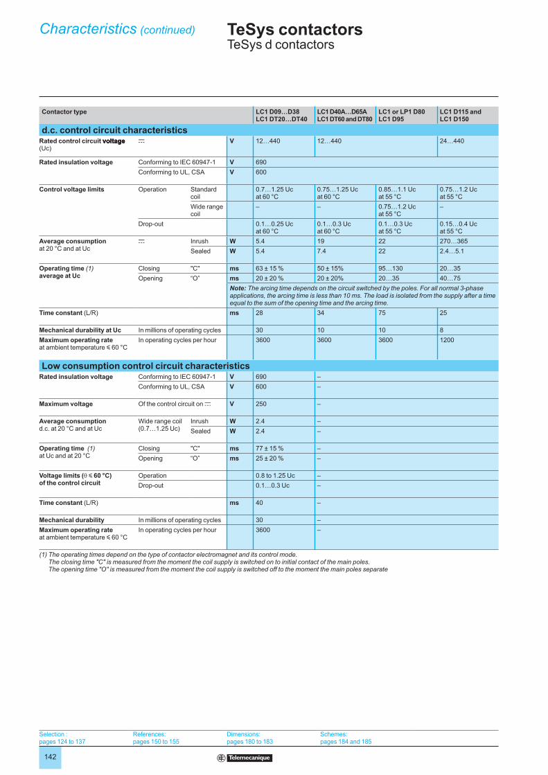
Contactor type LC1 D09…D38LC1 DT20…DT40
LC1 D40A…D65ALC1 DT60 and DT80
LC1 or LP1 D80LC1 D95
LC1 D115 andLC1 D150
d.c. control circuit characteristicsRated control circuit voltage voltagevoltage (Uc)
c V 12…440 12…440 24…440
Rated insulation voltage Conforming to IEC 60947-1 V 690
Conforming to UL, CSA V 600
Control voltage limits Operation Standard coil
0.7…1.25 Uc at 60 °C
0.75…1.25 Ucat 60 °C
0.85…1.1 Ucat 55 °C
0.75…1.2 Ucat 55 °C
Wide range coil
– – 0.75…1.2 Uc at 55 °C
–
Drop-out 0.1…0.25 Uc at 60 °C
0.1…0.3 Uc at 60 °C
0.1…0.3 Uc at 55 °C
0.15…0.4 Ucat 55 °C
Average consumptionat 20 °C and at Uc
c Inrush W 5.4 19 22 270…365
Sealed W 5.4 7.4 22 2.4…5.1
Operating time (1)average at Uc
Closing "C" ms 63 ± 15 % 50 ± 15% 95…130 20…35
Opening “O” ms 20 ± 20 % 20 ± 20% 20…35 40…75
Note: The arcing time depends on the circuit switched by the poles. For all normal 3-phase applications, the arcing time is less than 10 ms. The load is isolated from the supply after a time equal to the sum of the opening time and the arcing time.
Time constant (L/R) ms 28 34 75 25
Mechanical durability at Uc In millions of operating cycles 30 10 10 8
Maximum operating rateat ambient temperature y 60 °C
In operating cycles per hour 3600 3600 3600 1200
Low consumption control circuit characteristicsRated insulation voltage Conforming to IEC 60947-1 V 690 –
Conforming to UL, CSA V 600 –
Maximum voltage Of the control circuit on c V 250 –
Average consumptiond.c. at 20 °C and at Uc
Wide range coil (0.7…1.25 Uc)
Inrush W 2.4 –
Sealed W 2.4 –
Operating time (1) at Uc and at 20 °C
Closing "C" ms 77 ± 15 % –
Opening “O” ms 25 ± 20 % –
Voltage limits (θ y 60 °C) of the control circuit
Operation 0.8 to 1.25 Uc –
Drop-out 0.1…0.3 Uc –
Time constant (L/R) ms 40 –
Mechanical durability In millions of operating cycles 30 –
Maximum operating rateat ambient temperature y 60 °C
In operating cycles per hour 3600 –
(1) The operating times depend on the type of contactor electromagnet and its control mode. The closing time "C" is measured from the moment the coil supply is switched on to initial contact of the main poles. The opening time "O" is measured from the moment the coil supply is switched off to the moment the main poles separate
Characteristics (continued) TeSys contactorsTeSys d contactors
Selection :pages 124 to 137
References:pages 150 to 155
Dimensions:pages 180 to 183
Schemes:pages 184 and 185
143
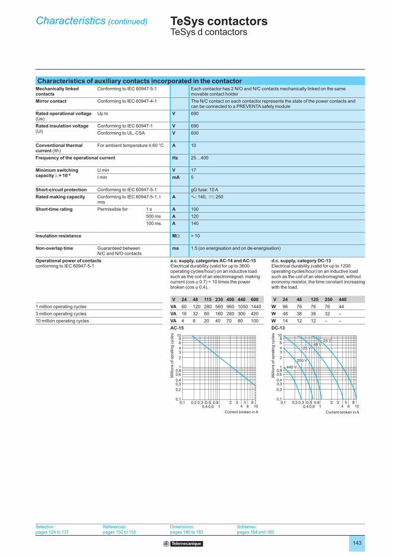
Characteristics of auxiliary contacts incorporated in the contactorMechanically linked contacts
Conforming to IEC 60947-5-1 Each contactor has 2 N/O and N/C contacts mechanically linked on the same movable contact holder
Mirror contact Conforming to IEC 60947-4-1 The N/C contact on each contactor represents the state of the power contacts and can be connected to a PREVENTA safety module
Rated operational voltage (Ue)
Up to V 690
Rated insulation voltage (Ui)
Conforming to IEC 60947-1 V 690
Conforming to UL, CSA V 600
Conventional thermal current (Ith)
For ambient temperature y 60 °C A 10
Frequency of the operational current Hz 25…400
Minimum switching capacity λ = 10–8
U min V 17
I min mA 5
Short-circuit protection Conforming to IEC 60947-5-1 gG fuse: 10 A
Rated making capacity Conforming to IEC 60947-5-1, I rms
A a: 140, c: 250
Short-time rating Permissible for 1 s A 100
500 ms A 120
100 ms A 140
Insulation resistance MΩ > 10
Non-overlap time Guaranteed between N/C and N/O contacts
ms 1.5 (on energisation and on de-energisation)
Operational power of contacts conforming to IEC 60947-5-1
a.c. supply, categories AC-14 and AC-15Electrical durability (valid for up to 3600 operating cycles/hour) on an inductive load such as the coil of an electromagnet: making current (cos ϕ 0.7) = 10 times the power broken (cos ϕ 0.4).
d.c. supply, category DC-13Electrical durability (valid for up to 1200 operating cycles/hour) on an inductive load such as the coil of an electromagnet, without economy resistor, the time constant increasing with the load.
V 24 48 115 230 400 440 600 V 24 48 125 250 440
1 million operating cycles VA 60 120 280 560 960 1050 1440 W 96 76 76 76 44
3 million operating cycles VA 16 32 80 160 280 300 420 W 48 38 38 32 –
10 million operating cycles VA 4 8 20 40 70 80 100 W 14 12 12 – –
AC-15 DC-13
0,1 0,2 0,3 0,50,4 0,6
0,81
2 34
56
810
0,1
0,2
0,30,4
0,60,8
1
2
34
68
10
Mill
ions o
f opra
ting c
ycle
s
Current broken in A
0,1 0,2 0,3 0,50,4 0,6
0,81
2 34
56
810
0,1
0,2
0,30,4
0,60,8
1
2
34
68
10
440 V
48 V
250 V
125 V
24 V
Current broken in A
Mill
ions o
f opra
ting c
ycle
s
Characteristics (continued) TeSys contactorsTeSys d contactors
Selection :pages 124 to 137
References:pages 150 to 155
Dimensions:pages 180 to 183
Schemes:pages 184 and 185

144
Contact block type LAD N or LAD C LAD T and LAD S LAD R LAD 8
EnvironmentConforming to standards IEC 60947-5-1, NF C 63-140, VDE 0660, BS 4794, EN 60947-5-1
Product certifications UL, CSA
Protective treatment Conforming to IEC 60068 “TH”
Degree of protection Conforming to VDE 0106 Protection against direct finger contact IP 2X
Ambient air temperature around the device
Storage °C - 60…+ 80
Operation °C - 5…+ 60
Permissible for operation at Uc °C - 40…+ 70
Maximum operating altitude Without derating m 3000
Connection by cable Phillips N° 2 and Ø 6 mm Flexible or solid cable with or without cable end
mm2 Min: 1 x 1; max: 2 x 2.5
Spring terminal connections Flexible or solid cable without cable end
mm2 Max: 2 x 2.5
Instantaneous and time delay contact characteristicsNumber of contacts 1, 2 or 4 2 2 2
Rated operational voltage (Ue)
Up to V 690
Rated insulation voltage (Ui)
Conforming to IEC 60947-5-1 V 690
Conforming to UL, CSA V 600
Conventional thermal current (Ith)
For ambient temperature y 60 °C
A 10
Frequency of the operational current Hz 25…400
Minimum switching capacity U min V 17
I min mA 5
Short-circuit protection Conforming to IEC 60947-5-1 and VDE 0660. gG fuse
A 10
Rated making capacity Conforming to IEC 60947-5-1
I rms A a: 140; c: 250
Short-time rating Permissible for 1 s A 100
500 ms A 120
100 ms A 140
Insulation resistance MΩ > 10
Non-overlap time Guaranteed between N/C and N/O contacts
ms 1.5 (on energisation and on de-energisation)
Overlap time Guaranteed between N/C and N/O contacts on LAD C22
ms 1.5 – – –
Time delay(LADT, R and S contact blocks)Accuracy only valid for setting range indicated on the front face
Ambient air temperature for operation
°C – - 40…+ 70 - 40…+ 70 –
Repeat accuracy – ± 2 % ± 2 % –
Drift up to 0.5 million operating cycles
– + 15 % + 15 % –
Drift depending on ambient air temperature
– 0.25 % per °C 0.25 % per °C –
Mechanical durability In millions of operating cycles 30 5 5 30
Operational power of contacts
See page 146
Characteristics TeSys contactorsAuxiliary contact blocks without dust and damp protected contacts for TeSys d contactors
References : page 167
Dimensions : page 180
Schemes : page 184
145
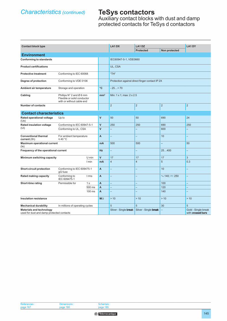
Contact block type LA1 DX LA1 DZ LA1 DY
Protected Non protected
EnvironmentConforming to standards IEC60947-5-1, VDE0660
Product certifications UL, CSA
Protective treatment Conforming to IEC 60068 “TH”
Degree of protection Conforming to VDE 0106 Protection against direct finger contact IP 2X
Ambient air temperature Storage and operation °C - 25…+ 70
Cabling Phillips N° 2 and Ø 6 mmFlexible or solid conductor with or without cable end
mm2 Min: 1 x 1; max: 2 x 2.5
Number of contacts 2 2 2 2
Contact characteristicsRated operational voltage(Ue)
Up to V 50 50 690 24
Rated insulation voltage (Ui)
Conforming to IEC 60947-5-1 V 250 250 690 250
Conforming to UL, CSA V – – 600 –
Conventional thermal current (Ith)
For ambient temperature y 40 °C
A – – 10 –
Maximum operational current(Ie)
mA 500 500 – 50
Frequency of the operational current Hz – – 25…400 –
Minimum switching capacity U min V 17 17 17 3
I min mA 4 4 5 0.3
Short-circuit protection Conforming to IEC 609475-1gG fuse
A – – 10 –
Rated making capacity Conforming to IEC 609475-1
I rms A – – a:140; c: 250 –
Short-time rating Permissible for 1 s A – – 100 –
500 ms A – – 120 –
100 ms A – – 140 –
Insulation resistance MΩ > 10 > 10 > 10 > 10
Mechanical durability In millions of operating cycles 5 5 30 5
Materials and technologyused for dust and damp protected contacts
Silver - Single break breakbreak Silver - Single break breakbreak – Gold - Single break with crossed bars crossed barscrossed bars
Characteristics (continued) TeSys contactorsAuxiliary contact blocks with dust and damp protected contacts for TeSys d contactors
References : page 167
Dimensions : page 180
Schemes : page 185

146
Rated operational power of contacts (conforming to IEC 60947-5-1)
a.c. supply, categories AC-14 and AC-15
Electrical durability (valid for up to 3600 operating cycles/hour) on an inductive load such as the coil of an electromagnet:
making current (cos ϕ 0.7) = 10 times the power broken (cos ϕ 0.4).
V 24 48 115 230 400 440 600
1 million operating cycles VA 60 120 280 560 960 1050 1440
3 million operating cycles VA 16 32 80 160 280 300 420
10 million operating cycles VA 4 8 20 40 70 80 100
0,1 0,2 0,3 0,4
0,5
0,6
0,7
0,8
0,9
1 2 3 4
5
6
7
8
9
100,1
0,2
0,3
0,4
0,6
0,5
0,80,7
7
1
2
3
5
4
6
8
10
Current broken in A
Mill
ions o
f opra
ting c
ycle
s
d.c. supply, category DC-13
Electrical durability (valid for up to 1200 operating cycles/hour) on an inductive load such as the coil of an electromagnet, without economy
resistor, the time constant increasing with the load.
V 24 48 125 250 440
1 million operating cycles W 120 90 75 68 61
3 million operating cycles W 70 50 38 33 28
10 million operating cycles W 25 18 14 12 10
0,1 0,2 0,3 0,4
0,5
0,6
0,7
0,8
0,9
1 2 3 4
5
6
7
8
9
100,1
0,2
0,3
0,4
0,6
0,5
0,80,7
7
1
2
3
5
4
6
8
10
440 V
48 V
250 V
125 V
24 V
Current broken in A in A
Mill
ions o
f opera
ting c
ycle
s
Characteristics (continued) TeSys contactorsAuxiliary contact blocks with dust and damp protected contacts for TeSys d contactors
References : page 167
Dimensions : page 180
Schemes : page 184
147
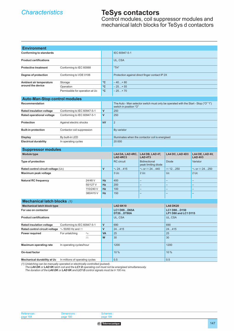
EnvironmentConforming to standards IEC 60947-5-1
Product certifications UL, CSA
Protective treatment Conforming to IEC 60068 “TH”
Degree of protection Conforming to VDE 0106 Protection against direct finger contact IP 2X
Ambient air temperature around the device
Storage °C – 40…+ 80
Operation °C – 25…+ 55
Permissible for operation at Uc °C – 25…+ 70
Auto-Man-Stop control modulesRecommendation The Auto - Man selector switch must only be operated with the Start - Stop (“O” “I”)
switch in position “O”
Rated insulation voltage Conforming to IEC 60947-5-1 V 250
Rated operational voltage Conforming to IEC 60947-5-1 V 250
Protection Against electric shocks kV 2
Built-in protection Contactor coil suppression By varistor
Display By built-in LED Illuminates when the contactor coil is energised
Electrical durability In operating cycles 20 000
Suppressor modulesModule type LA4 DA, LAD 4RC,
LAD 4RC3LA4 DB, LAD 4T,LAD 4T3
LA4 DC, LAD 4D3 LA4 DE, LAD 4V,LAD 4V3
Type of protection RC circuit Bidirectional peak limiting diode
Diode Varistor
Rated control circuit voltage (Uc) V a 24…415 a or c 24…440 c 12…250 a or c 24…250
Maximum peak voltage 3 Uc 2 Uc Uc 2 Uc
Natural RC frequency 24/48 V Hz 400 – – –
50/127 V Hz 200 – – –
110/240 V Hz 100 – – –
380/415 V Hz 150 – – –
Mechanical latch blocks (1)
Mechanical latch block type LAD 6K10 LA6 DK20
For use on contactor LC1 D09…D65ADT20…DT80A
LC1 D80…D150LP1 D80 and LC1 D115
Product certifications UL, CSA UL, CSA
Rated insulation voltage Conforming to IEC 60947-5-1 V 690 690
Rated control circuit voltage a 50/60 Hz and c V 24…415 24…415
Power required For unlatching a VA 25 25
c W 30 30
Maximum operating rate In operating cycles/hour 1200 1200
On-load factor 10 % 10 %
Mechanical durability at Uc In millions of operating cycles 0.5 0.5
(1) Unlatching can be manually operated or electrically controlled (pulsed). The LA6 DK or LAD 6K latch coil and the LC1 D operating coil must not be energised simultaneously. The duration of the LA6 DK or LAD 6K and LC1 D control signals must be u 100 ms.
Characteristics TeSys contactorsControl modules, coil suppressor modules and mechanical latch blocks for TeSys d contactors
References : page 168
Dimensions : page 180
Schemes : page 184
148
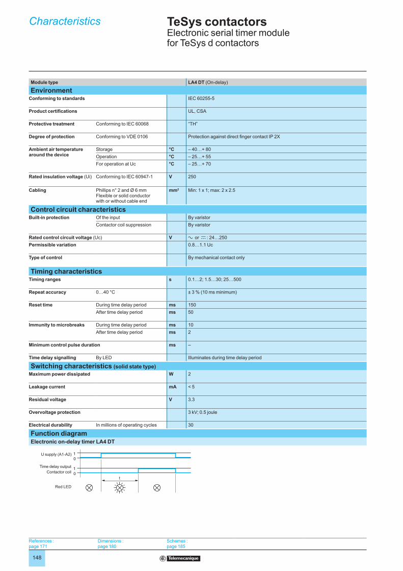
Module type LA4 DT (On-delay)
EnvironmentConforming to standards IEC 60255-5
Product certifications UL, CSA
Protective treatment Conforming to IEC 60068 “TH”
Degree of protection Conforming to VDE 0106 Protection against direct finger contact IP 2X
Ambient air temperature around the device
Storage °C – 40…+ 80
Operation °C – 25…+ 55
For operation at Uc °C – 25…+ 70
Rated insulation voltage (Ui) Conforming to IEC 60947-1 V 250
Cabling Phillips n° 2 and Ø 6 mmFlexible or solid conductor with or without cable end
mm2 Min: 1 x 1; max: 2 x 2.5
Control circuit characteristicsBuilt-in protection Of the input By varistor
Contactor coil suppression By varistor
Rated control circuit voltage (Uc) V a or c : 24…250
Permissible variation 0.8…1.1 Uc
Type of control By mechanical contact only
Timing characteristicsTiming ranges s 0.1…2; 1.5…30; 25…500
Repeat accuracy 0…40 °C ± 3 % (10 ms minimum)
Reset time During time delay period ms 150
After time delay period ms 50
Immunity to microbreaks During time delay period ms 10
After time delay period ms 2
Minimum control pulse duration ms –
Time delay signalling By LED Illuminates during time delay period
Switching characteristics (solid state type)
Maximum power dissipated W 2
Leakage current mA < 5
Residual voltage V 3.3
Overvoltage protection 3 kV; 0.5 joule
Electrical durability In millions of operating cycles 30
Function diagramElectronic on-delay timer LA4 DT
0
1
0
1
t
U supply (A1-A2)
Time delay output
Contactor coil
Red LED
Characteristics TeSys contactorsElectronic serial timer module for TeSys d contactors
References : page 171
Dimensions : page 180
Schemes : page 185
149
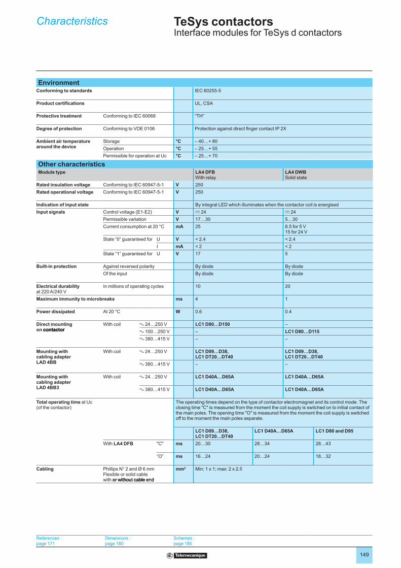
EnvironmentConforming to standards IEC 60255-5
Product certifications UL, CSA
Protective treatment Conforming to IEC 60068 “TH”
Degree of protection Conforming to VDE 0106 Protection against direct finger contact IP 2X
Ambient air temperature around the device
Storage °C – 40…+ 80
Operation °C – 25…+ 55
Permissible for operation at Uc °C – 25…+ 70
Other characteristicsModule type LA4 DFB
With relayLA4 DWBSolid state
Rated insulation voltage Conforming to IEC 60947-5-1 V 250
Rated operational voltage Conforming to IEC 60947-5-1 V 250
Indication of input state By integral LED which illuminates when the contactor coil is energised
Input signals Control voltage (E1-E2) V c 24 c 24
Permissible variation V 17…30 5…30
Current consumption at 20 °C mA 25 8.5 for 5 V15 for 24 V
State “0” guaranteed for U V < 2.4 < 2.4
I mA < 2 < 2
State “1” guaranteed for U V 17 5
Built-in protection Against reversed polarity By diode By diode
Of the input By diode By diode
Electrical durability at 220 A/240 V
In millions of operating cycles 10 20
Maximum immunity to microbreaks ms 4 1
Power dissipated At 20 °C W 0.6 0.4
Direct mounting on contactor contactorcontactor
With coil a 24…250 V LC1 D80…D150 –
a 100…250 V – LC1 D80…D115
a 380…415 V – –
Mounting with cabling adapter LAD 4BB
With coil a 24…250 V LC1 D09…D38, LC1 DT20…DT40
LC1 D09…D38, LC1 DT20…DT40
a 380…415 V – –
Mounting withcabling adapter LAD 4BB3
With coil a 24…250 V LC1 D40A…D65A LC1 D40A…D65A
a 380…415 V LC1 D40A…D65A LC1 D40A…D65A
Total operating time at Uc (of the contactor)
The operating times depend on the type of contactor electromagnet and its control mode. The closing time "C" is measured from the moment the coil supply is switched on to initial contact of the main poles. The opening time "O" is measured from the moment the coil supply is switched off to the moment the main poles separate.
LC1 D09…D38, LC1 DT20…DT40
LC1 D40A…D65A LC1 D80 and D95
With LA4 DFB "C" ms 20…30 28…34 28…43
“O” ms 16…24 20…24 18…32
Cabling Phillips N° 2 and Ø 6 mmFlexible or solid cable with or without cable end or without cable endor without cable end
mm2 Min: 1 x 1; max: 2 x 2.5
Characteristics TeSys contactorsInterface modules for TeSys d contactors
References : page 171
Dimensions : page 180
Schemes : page 185

150
3-pole contactorsStandard power ratings of 3-phase motors 50-60 Hz in category AC-3(θ y 60 °C)
Rated opera-tional current in AC-3 440 Vup to
Instan-taneous auxiliary contacts
Basic reference, to be completed by adding the control voltage code (2)
Weight (3)
Fixing (1)
220 V 230 V
380 V400 V
415 V 440 V 500 V 660 V 690 V
1000 V
kW kW kW kW kW kW kW A kg
Connection by screw clamp terminals or connectors
2.2 4 4 4 5.5 5.5 – 9 1 1 LC1 D09pp 0.320
3 5.5 5.5 5.5 7.5 7.5 – 12 1 1 LC1 D12pp 0.325
4 7.5 9 9 10 10 – 18 1 1 LC1 D18pp 0.330
5.5 11 11 11 15 15 – 25 1 1 LC1 D25pp 0.370
7.5 15 15 15 18.5 18.5 – 32 1 1 LC1 D32pp 0.375
9 18.5 18.5 18.5 18.5 18.5 – 38 1 1 LC1 D38pp 0.380
11 18.5 22 22 22 30 – 40 1 1 LC1 D40App (4) 0.850
15 22 25 30 30 33 – 50 1 1 LC1 D50App (4) 0.855
18.5 30 30 30 37 37 – 65 1 1 LC1 D65App (4) 0.860
22 37 45 45 55 45 45 80 1 1 LC1 D80pp (4) 1.590
25 45 45 45 55 45 45 95 1 1 LC1 D95pp (4) 1.610
30 55 59 59 75 80 65 115 1 1 LC1 D115pp (4) 2.500
40 75 80 80 90 100 75 150 1 1 LC1 D150pp (4) 2.500
Connection by lugs or bars
In the references selected above, insert a figure 6 before the voltage code.
Example: LC1 D09pp becomesLC1 D096pp.
Separate componentsAuxiliary contact blocks and add-on modules: see pages 167 to 173.
(1) LC1 D09 to D65A: clip-on mounting on 35 mm 5 rail AM1 DP or screw fixing. LC1 D80 to D95 a: clip-on mounting on 35 mm 5 rail AM1 DP or 75 mm 5 rail AM1 DL or screw fixing. LC1 D80 to D95 c : clip-on mounting on 75 mm 5 rail AM1 DL or screw fixing. LC1 D115 and D150: clip-on mounting on 2 x 35 mm 5 rails AM1 DP or screw fixing.
(2) Standard control circuit voltages (for other voltages, please consult your Regional Sales Office):
a.c. supply
Volts 24 42 48 110 115 220 230 240 380 400 415 440 500
LC1 D09…D150 (D115 and D150 coils with built-in suppression as standard, by bi-directional peak limiting diode).
50/60 Hz B7 D7 E7 F7 FE7 M7 P7 U7 Q7 V7 N7 R7 S7
LC1 D80…D115
50 Hz B5 D5 E5 F5 FE5 M5 P5 U5 Q5 V5 N5 R5 S5
60 Hz B6 – E6 F6 – M6 – U6 Q6 – – R6 –
d.c. supply
Volts 12 24 36 48 60 72 110 125 220 250 440
LC1 D09…D65A (coils with integral suppression device fitted as standard)
U 0.75…1.25 Uc JD BD CD ED ND SD FD GD MD UD RD
LC1 D80…D95
U 0.85…1.1 Uc JD BD CD ED ND SD FD GD MD UD RD
U 0.75…1.2 Uc JW BW CW EW – SW FW – MW – –
LC1 D115 and D150 (coils with integral suppression device fitted as standard)
U 0.75…1.2 Uc – BD – ED ND SD FD GD MD UD RD
Low consumption
Volts c 5 12 20 24 48 110 220 250
LC1 D09...D38 (coils with integral suppression device fitted as standard)
U 0.8…1.25 Uc AL JL ZL BL EL FL ML UL
For other voltages between 5 and 690 V, see pages 174 to 179.(3) The weights indicated are for contactors with a.c. control circuit. For d.c. or low consumption control circuit, add 0.160 kg from
LC1 D09 to D38, 0.100 kg from LC1 D40A to D65A and 1 kg for LC1 D80 and D95.(4 ) For low consumption kit LA4 DBL (see page 171).
References TeSys contactorsTeSys d contactors for motor control up to 75 kW at 400 V, in category AC-3For connection by screw clamp terminals and lugs
Selection : pages 124 to 137
Characteristics : page 138
Dimensions : page 180
Schemes : page 184
LC1 D09pp
810356
LC1 D25pp
810353
LC1 D65App
106896
LC1 D95pp
810352
LC1 D115pp
105517
151
3-pole contactorsStandard power ratings of 3-phase motors 50-60 Hz in category AC-3(θ y 60 °C)
Rated opera-tional current in AC-3 440 Vup to
Instan-taneous auxiliary contacts
Basic reference, to be completed by adding the control voltage code (2)
Weight(3)
Fixing (1)
220 V 230 V
380 V400 V
415 V 440 V 500 V 660 V 690 V
1000 V
kW kW kW kW kW kW kW A kg
Power and control connections by spring terminals
2.2 4 4 4 5.5 5.5 9 1 1 LC1 D093pp 0.320
3 5.5 5.5 5.5 7.5 7.5 12 1 1 LC1 D123pp 0.325
4 7.5 9 9 10 10 18 1 1 LC1 D183pp 0.330
5.5 11 11 11 15 15 25 1 1 LC1 D253pp 0.370
7.5 15 15 15 18.5 18.5 32 (4) 1 1 LC1 D323pp 0.375
Power connection by EverLink® BTR screw connectors (5) and control by spring terminals
11 18.5 22 22 22 30 40 1 1 LC1 D40A3pp 0.850
15 22 25 30 30 33 50 1 1 LC1 D50A3pp 0.855
18.5 30 30 30 37 37 65 1 1 LC1 D65A3pp 0.860
Connection by Faston connectors
These contactors are fitted with Faston connectors: 2 x 6.35 mm on the power poles and 1 x 6.35 mm on the coil
and auxiliary terminals. It is possible to make 2 x 6.35 mm connections to the coil terminals by using a double
Faston connector, reference: LA9 6180, to be ordered separately (sold in lots of 100).
For contactors LC1 D09 and LC1 D12 only, replace the figure 3 with a 9 in the references selected above.
Example: LC1 D093pp becomes LC1 D099pp.
Separate componentsAuxiliary contact blocks and add-on modules: see pages 167 to 173.
(1) LC1 D09 to D32: clip-on mounting on 35 mm 5 rail AM1 DP or screw fixing.(2) Standard control circuit voltages (for other voltages, please consult your Regional Sales Office):
a.c. supply
Volts 24 42 48 110 115 220 230 240 380 400 415 440
LC1 D09…D65A
50/60 Hz B7 D7 E7 F7 FE7 M7 P7 U7 Q7 V7 N7 R7
d.c. supply
Volts 12 24 36 48 60 72 110 125 220 250 440
LC1 D09…D65A (coils with built-in suppression as standard, by bi-directional peak limiting diode)
U 0.75…1.25 Uc JD BD CD ED ND SD FD GD MD UD RD
Low consumption
Volts c 5 12 20 24 48 110 220 250
LC1 D09...D32 (coils with integral suppression device fitted as standard)
U 0.8…1.25 Uc AL JL ZL BL EL FL ML UL
For other voltages between 5 and 690 V, see pages 174 to 179.(3) The weights indicated are for contactors with a.c. control circuit. For d.c. or low consumption control circuit, add 0.160 kg from
LC1 D09 to D32.(4) Must be wired with 2 x 4 mm2 cables in parallel on the upstream side. On the downstream side. outgoing terminal block
LAD 331 may be used (Quickfit technology, see page 223). When wired with a single cable, the product is limited to 25 A (11 kW/400 V motors).
(5) BTR screws: hexagon socket head. In accordance with local electrical wiring regulations, a size 4 insulated Allen key must be used (reference LAD ALLEN4, see page 173).
References TeSys contactorsTeSys d contactors for motor control up to 30 kW at 400 V, in category AC-3For connection by spring terminals
LC1 D123pp
510671
LC1 D65A3pp
510670
Selection : pages 124 to 137
Characteristics : page 138
Dimensions : page 180
Schemes : page 184

152
3-pole contactors for connection by screw clamp terminals or connectorsNon inductive loads maximum current (θ y 60 °C)utilisation category AC-1
Number of poles
Instan-taneous auxiliary contacts
Basic reference, to be completed by adding the voltage code (1)
Weight (3)
\
Fixing (2)
A kg
25 3 1 1 LC1 D09pp 0.320
or LC1 D12pp 0.325
32 3 1 1 LC1 D18pp 0.330
40 3 1 1 LC1 D25pp 0.370
50 3 1 1 LC1 D32pp 0.375
or LC1 D38pp 0.380
60 3 1 1 LC1 D40App (6) 0.850
80 3 1 1 LC1 D50App (6) 0.855
or LC1 D65App (4) (6) 0.860
125 3 1 1 LC1 D80pp 1.590
or LC1 D95pp (4) 1.610
200 3 1 1 LC1 D115pp 2.500
or LC1 D150pp (5) 2.500
3-pole contactors for connection by lugsIn the references selected above, insert a figure 6 before the voltage code.
Example: LC1 D09pp becomes LC1 D096pp.
(1) Standard control circuit voltages (for other voltages, please consult your Regional Sales Office):
a.c. supply
Volts 24 42 48 110 115 220 230 240 380 400 415 440 500
LC1 D09...D150 and LC1 DT20...DT40 (coils with integral suppression device fitted as standard)
50/60 Hz B7 D7 E7 F7 FE7 M7 P7 U7 Q7 V7 N7 R7 –
LC1 D80...D115
50 Hz B5 D5 E5 F5 FE5 M5 P5 U5 Q5 V5 N5 R5 S5
60 Hz B6 – E6 F6 – M6 – U6 Q6 – – R6 –
d.c. supply
Volts 12 24 36 48 60 72 110 125 220 250 440
LC1 D09...D65A and LC1 DT20...DT80A (coils with integral suppression device fitted as standard)
U 0.7…1.25 Uc JD BD CD ED ND SD FD GD MD UD RD
LC1 or LP1 D40...D80
U 0.85…1.1 Uc JD BD CD ED ND SD FD GD MD UD RD
U 0.75…1.2 Uc JW BW CW EW – SW FW – MW – –
LC1 D115 (coils with integral suppression device fitted as standard)
U 0.75…1.2 Uc – BD – ED ND SD FD GD MD UD RD
Low consumption
Volts c 5 12 20 24 48 110 220 250
LC1 D09...D38 and LC1 DT20...DT40 (coils with integral suppression device fitted as standard)
U 0.8…1.25 Uc AL JL ZL BL EL FL ML UL
For other voltages between 5 and 690 V, see pages 174 to 179.(2) LC1 D09 to D38 and LC1 DT20 to DT40: clip-on mounting on 35 mm 5 rail AM1DP or screw fixing
LC1 D40 to D95 a: clip-on mounting on 35 mm 5 rail AM1 DP or 75 mm 5 rail AM1 DL or screw fixing. LC1 or LP1 D40 to D95 c: clip-on mounting on 75 mm 5 rail AM1 DL or screw fixing. LC1 D115 and D150: clip-on mounting on two 35 mm 5 rails AM1 DP or screw fixing.(3) The weights indicated are for contactors with a.c. control circuit. For d.c. or low consumption control circuit, add 0.160 kg from
LC1 D09 to D38, 0.785 kg from LC1 D40 to D65 and 1 kg for LC1 D80 and D95.(4) Selection according to the number of operating cycles, see AC-1 curve, page 128.(5) 32 A with 2 x 4 mm2 cables connected in parallel.(6) For low consumption kit LA4 DBL (see page 171).
LC1 D09pp
810356
LC1 D09pp
810356
LC1 D65App
106896
LC1 D65App
106896
Selection : pages 124 to 137
Characteristics :pages 138 to 143
Dimensions :page 180
Schemes :page 184
Selection : pages 124 to 137
Characteristics :pages 138 to 143
Dimensions :page 180
Schemes :page 184
References TeSys contactorsTeSys d 3-pole contactors for control in category AC-1, 25 to 200 A
153
3-pole contactors for connection by Faston connectorsThese contactors are fitted with Faston connectors: 2 x 6.35 mm on the power poles and 1 x 6.35 mm on the coil
terminals. It is possible to make 2 x 6.35 mm connections to the coil terminals by using a double Faston
connector, reference: LAD 99635, to be ordered separately (sold in lots of 100).
For contactors LC1 D09 and LC1 D12 only, in the references selected page 24502/2, insert a figure 9 before the
voltage code. Example: LC1 D09pp becomes LC1 D099pp.
3-pole contactors for connection by spring terminalsNon inductive loads maximum current (θ y 60 °C)utilisation category AC-1
Number of poles
Instan-taneous auxiliary contacts
Basic reference, to be completed by adding the voltage code (1)
Weight(3)
Fixing (2)
A kg
16 3 1 1 LC1 D093pp (4) 0.320
or LC1 D123pp (4) 0.325
25 3 1 1 LC1 D183pp (5) 0.335
or LC1 D253pp (6) 0.325
or LC1 D323pp (6) 0.325
60 3 1 1 LC1 D40A3pp (8) 0.850
80 3 1 1 LC1 D50A3pp (8) 0.855
or LC1 D65A3pp (7) (8) 0.860
Component partsAuxiliary contact blocks and add-on modules: see pages 168 to 173.
(1) Standard control circuit voltages (for other voltages, please consult your Regional Sales Office):
a.c. supply
Volts 24 42 48 110 115 220 230 240 380 400 415 440 500
LC1 D09...D150 and LC1 DT20...DT40 (coils with integral suppression device fitted as standard)
50/60 Hz B7 D7 E7 F7 FE7 M7 P7 U7 Q7 V7 N7 R7 –
LC1 D80...D115
50 Hz B5 D5 E5 F5 FE5 M5 P5 U5 Q5 V5 N5 R5 S5
60 Hz B6 – E6 F6 – M6 – U6 Q6 – – R6 –
d.c. supply
Volts 12 24 36 48 60 72 110 125 220 250 440
LC1 D09...D65A and LC1 DT20...DT80A (coils with integral suppression device fitted as standard)
U 0.7…1.25 Uc JD BD CD ED ND SD FD GD MD UD RD
LC1 or LP1 D40...D80
U 0.85…1.1 Uc JD BD CD ED ND SD FD GD MD UD RD
U 0.75…1.2 Uc JW BW CW EW – SW FW – MW – –
LC1 D115 (coils with integral suppression device fitted as standard)
U 0.75…1.2 Uc – BD – ED ND SD FD GD MD UD RD
Low consumption
Volts c 5 12 20 24 48 110 220 250
LC1 D09...D38 and LC1 DT20...DT40 (coils with integral suppression device fitted as standard)
U 0.8…1.25 Uc AL JL ZL BL EL FL ML UL
For other voltages between 5 and 690 V, see pages 174 to 179.(2) LC1 D09 to D38 and LC1 DT20 to DT40: clip-on mounting on 35 mm 5 rail rail AM1DP or screw fixing.
LC1 D40 to D95 a: clip-on mounting on 35 mm 5 rail AM1 DP or 75 mm 5 rail AM1 DL or screw fixing. LC1 or LP1 D40 to D95 c: clip-on mounting on 75 mm 5 rail AM1 DL or screw fixing. LC1 D115 and D150: clip-on mounting on 35 mm 5 rail AM1 DP or screw fixing.(3) The weights indicated are for contactors with a.c. control circuit. For d.c. or low consumption control circuit, add 0.160 kg from
LC1 D09 to D38, 0.785 kg from LC1 D40 to D65 and 1 kg for LC1 D80 and D95.(4) 20 A with 2 x 2.5 mm2 cables connected in parallel.(5) 32 A with 2 x 4 mm2 cables connected in parallel.(6) 40 A with 2 x 4 mm2 cables connected in parallel.(7) Selection according to the number of operating cycles, see AC-1 curve, page 128.(8) For low consumption kit LA4 DBL (see page 171).
LC1 D123pp
102862
LC1 D123pp
102862
LC1 D65A3pp
510670
LC1 D65A3pp
510670
Selection : pages 124 to 137
Characteristics :pages 138 to 143
Dimensions :page 180
Schemes :page 184
Selection : pages 124 to 137
Characteristics :pages 138 to 143
Dimensions :page 180
Schemes :page 184
References (continued) TeSys contactorsTeSys d 3-pole contactors for control in category AC-1, 25 to 200 A
154
4-pole contactors for connection by screw clamp terminals or connectorsNon inductive loads maximum current (θ y 60 °C)utilisation category AC-1
Number of poles
Instan-taneous auxiliary contacts
Basic reference, to be completed by adding the voltage code (1)
Weight(3)
Fixing (2)
A kg
20 4 – 1 1 LC1 DT20pp 0.365
2 2 1 1 LC1 D098pp 0.365
25 4 – 1 1 LC1 DT25pp 0.365
2 2 1 1 LC1 D128pp 0.365
32 4 – 1 1 LC1 DT32pp 0.425
2 2 1 1 LC1 D188pp 0.425
40 4 – 1 1 LC1 DT40pp 0.425
2 2 1 1 LC1 D258pp 0.425
60 4 – 1 1 LC1 DT60App (4) 1.090
2 2 – – LC1 D40008pp 1.440
or LP1 D40008pp 2.210
80 4 – 1 1 LC1 DT80App (4) 1.150
2 2 – – LC1 D65008pp 1.450
or LP1 D65008pp 2.220
125 4 – – – LC1 D80004pp 1.760
or LP1 D80004pp 2.685
2 2 – – LC1 D80008pp 1.840
or LP1 D80008pp 2.910
200 4 – – – LC1 D115004pp 2.860
4-pole contactors for connection by lugs or barsIn the references selected above, insert a figure 6 before the voltage code.
Example: LC1 DT20pp becomes LC1 DT206pp.
(1) Standard control circuit voltages (for other voltages, please consult your Regional Sales Office):
a.c. supply
Volts 24 42 48 110 115 220 230 240 380 400 415 440 500
LC1 D09...D150 and LC1 DT20...DT40 (coils with integral suppression device fitted as standard)
50/60 Hz B7 D7 E7 F7 FE7 M7 P7 U7 Q7 V7 N7 R7 –
LC1 D80...D115
50 Hz B5 D5 E5 F5 FE5 M5 P5 U5 Q5 V5 N5 R5 S5
60 Hz B6 – E6 F6 – M6 – U6 Q6 – – R6 –
d.c. supply
Volts 12 24 36 48 60 72 110 125 220 250 440
LC1 D09...D65A and LC1 DT20...DT80A (coils with integral suppression device fitted as standard)
U 0.7…1.25 Uc JD BD CD ED ND SD FD GD MD UD RD
LC1 or LP1 D40...D80
U 0.85…1.1 Uc JD BD CD ED ND SD FD GD MD UD RD
U 0.75…1.2 Uc JW BW CW EW – SW FW – MW – –
LC1 D115 (coils with integral suppression device fitted as standard)
U 0.75…1.2 Uc – BD – ED ND SD FD GD MD UD RD
Low consumption
Volts c 5 12 20 24 48 110 220 250
LC1 D09...D38 and LC1 DT20...DT40 (coils with integral suppression device fitted as standard)
U 0.8…1.25 Uc AL JL ZL BL EL FL ML UL
For other voltages between 5 and 690 V, see pages 174 to 179.(2) LC1 D09 to D38 and LC1 DT20 to DT40: clip-on mounting on 35 mm 5 rail AM1DP or screw fixing.
LC1 D40 to D95 a: clip-on mounting on 35 mm 5 rail AM1 DP or 75 mm 5 rail AM1 DL or screw fixing. LC1 or LP1 D40 to D95 c clip-on mounting on 75 mm 5 rail AM1 DL or screw fixing. LC1 D115 and D150: clip-on mounting on 35 mm 5 rail AM1 DP or screw fixing.(3) The weights indicated are for contactors with a.c. control circuit. For d.c. or low consumption control circuit, add 0.160 kg from
LC1 D09 to D38, 0.785 kg from LC1 D40 to D65 and 1 kg for LC1 D80 and D95.(4) For low consumption kit LA4 DBL (see page 171).
LC1 DT20pp
565131
LC1 DT20pp
565131
LC1 D65ppp
537728
LC1 D65ppp
537728
LC1 DT80pp
106903
LC1 DT80pp
106903
Selection : pages 124 to 137
Characteristics :pages 138 to 143
Dimensions :page 180
Schemes :page 184
Selection : pages 124 to 137
Characteristics :pages 138 to 143
Dimensions :page 180
Schemes :page 184
References (continued) TeSys contactorsTeSys d 3-pole contactors for control in category AC-1, 25 to 200 A
155
4-pole contactors for connection by spring terminalsNon inductive loads maximum current (θ y 60 °C)utilisation category AC-1
Number of poles
Instan-taneous auxiliary contacts
Basic reference, to be completed by adding the voltage code (1)
Weight(3)
Fixing (2)
A kg
20 4 – 1 1 LC1 DT203pp 0.380
2 2 1 1 LC1 D0983pp 0.380
25 4 – 1 1 LC1 DT253pp 0.380
2 2 1 1 LC1 D1283pp 0.380
32 4 – 1 1 LC1 DT323pp 0.425
2 2 1 1 LC1 D1883pp 0.425
40 4 – 1 1 LC1 DT403pp 0.425
2 2 1 1 LC1 D2583pp 0.425
4-pole contactors for connection by EverLink®, BTR screw connectors and control circuit by spring terminals
60 4 – 1 1 LC1 DT60A3pp (4) 1.090
80 4 – 1 1 LC1 DT80A3pp (4) 1.150
Component partsAuxiliary contact blocks and add-on modules: see pages 168 to 173.
(1) Standard control circuit voltages (for other voltages, please consult your Regional Sales Office):
a.c. supply
Volts 24 42 48 110 115 220 230 240 380 400 415 440 500
LC1 D09...D150 and LC1 DT20...DT40 (coils with integral suppression device fitted as standard)
50/60 Hz B7 D7 E7 F7 FE7 M7 P7 U7 Q7 V7 N7 R7 –
LC1 D80...D115
50 Hz B5 D5 E5 F5 FE5 M5 P5 U5 Q5 V5 N5 R5 S5
60 Hz B6 – E6 F6 – M6 – U6 Q6 – – R6 –
d.c. supply
Volts 12 24 36 48 60 72 110 125 220 250 440
LC1 D09...D65A and LC1 DT20...DT80A (coils with integral suppression device fitted as standard)
U 0.7…1.25 Uc JD BD CD ED ND SD FD GD MD UD RD
LC1 or LP1 D40...D80
U 0.85…1.1 Uc JD BD CD ED ND SD FD GD MD UD RD
U 0.75…1.2 Uc JW BW CW EW – SW FW – MW – –
LC1 D115 (coils with integral suppression device fitted as standard)
U 0.75…1.2 Uc – BD – ED ND SD FD GD MD UD RD
Low consumption
Volts c 5 12 20 24 48 110 220 250
LC1 D09...D38 and LC1 DT20...DT40 (coils with integral suppression device fitted as standard)
U 0.8…1.25 Uc AL JL ZL BL EL FL ML UL
For other voltages between 5 and 690 V, see pages 174 to 179.(2) LC1 D09 to D38 and LC1 DT20 to DT40: clip-on mounting on 35 mm 5 rail AM1DP or screw fixing.
LC1 D40 to D95 a: clip-on mounting on 35 mm 5 rail AM1 DP or 75 mm 5 rail AM1 DL or screw fixing. LC1 or LP1 D40 to D95 c: clip-on mounting on 75 mm 5 rail AM1 DL or screw fixing. LC1 D115 and D150: clip-on mounting on 35 mm 5 rail AM1 DP or screw fixing.(3) The weights indicated are for contactors with a.c. control circuit. For d.c. or low consumption control circuit, add 0.160 kg from
LC1 D09 to D38, 0.785 kg from LC1 D40 to D65 and 1 kg for LC1 D80 and D95.(4) For low consumption kit LA4 DBL (see page 171).
Selection : pages 124 to 137
Characteristics :pages 138 to 143
Dimensions :page 180
Schemes :page 184
Selection : pages 124 to 137
Characteristics :pages 138 to 143
Dimensions :page 180
Schemes :page 184
References (continued) TeSys contactorsTeSys d 3-pole contactors for control in category AC-1, 25 to 200 A

156
Starters for the North American marketIn recent years, the North American market has started to harmonise UL, CSA and
ANCE standards, as well as the industrial installation codes provided by national
regulations (NEC for the United States, CEC for Canada and MEC for Mexico). (1)
Major improvements, carried out by the Canena (2) are aimed at harmonising
product requirements based on IEC (3) standards.
However, the North American codes use specific terminology for defining the
functions of a starter.
These functions can be fulfilled by standard IEC products, accompanied by
appropriate certifications.
Combination StartersCombination Starters are the most common type of packaged motor starter. They
are called "Combination" because of their structure and their combined functions.
The figure opposite shows the four combined functions that constitute a complete
motor starter circuit, defined as a “Motor branch circuit” by the NEC (US National
Electric Code) in article 430. Standard UL508 currently gives different types of
combination starter that meet the requirements of a "Motor branch circuit".
Type E, called “self-protected combination starter”, covers all these functions and
can be controlled manually (thermal-magnetic circuit-breaker) or remotely
(starter-controller). Type E starters withstand faults within their declared nominal
rating without sustaining damage, after which they can be put back into service. In
addition, they can withstand more severe short-circuit and durability performance
tests without welding or excessive wear of the contact tips.
Type F, called “Combination motor starter”, consists of a type E manual starter
(thermal-magnetic circuit-breaker) combined with a contactor.
These starters are evaluated by means of basic short-circuit tests, but are not
considered as “self-protected”.
For this combination, the type E starter must be marked “Combination Motor
Controller when used with ...”, followed by the reference of the load side contactor.
(1) UL: Underwriters Laboratories, CSA: Canadian Standards Association, ACNE: Association of Standardization and Certification, NEC: National Electric Code, CEC: Canadian Electrical Code, MEC: Mexican Electrical Code.
(2) Canena: Council for Harmonization of Electrotechnical Standardization of North America.(3) IEC: International Electrotechnical Commission.
Presentation TeSys contactorsfor the North American market,conforming to UL and CSA
M
1
2
3
4
Motor Disconnect (Disconnect switch)
Motor Branch Circuit Protection (Short-circuit
protection)
Motor Controller (Contactor)
Motor Overload Protection (Thermal overload relay)
1 2
3 4
157
Control panels
To help users properly coordinate their motor control equipment with their distribution
system in the event of a fault, article 409 of the 2005 NEC requires panel builders to
list the short-circuit withstand rating of their motor control panels.
According to standard UL508A, manufacturers must use the short-circuit withstand
value of the lowest rated device as the nominal withstand rating of the panel, unless
the devices have been tested together for a higher coordinated rating.
The minimum “short-circuit current rating” (SCCR), on motor control components
for horsepower ratings of 50 hp or below is 5 000 A.
Using a type E or type F combination starter eliminates the coordination problems
of using individual components for the “motor branch circuit protection”, “motor
controller” and “motor overload protection” functions.
The panel builder uses the declared short-circuit current rating for the combination
starter. This value is generally higher than 5 000 A.
This makes it easier to list the short-circuit current ratings and to check the
compatibility of a UL508A motor control panel within a given distribution system.
Presentation (continued) TeSys contactorsfor the North American market,conforming to UL and CSA
158
Group protection
Article 430.53 of the NEC allows a single short-circuit protection device to be used
for more than one motor circuit if the components used are marked and listed for
such use.
Components suitable for use in group protection, known as “motor group installations”, can be marked in one of the following two ways:
Case n° 1
The contactor and the motor overload relay are both listed as suitable for group
installation.
An inverse time circuit-breaker can be used as the short-circuit protection device if it
is also listed as suitable for group installation.
The panel builder must therefore make sure that the short-circuit protection device
selected (fuses or inverse time circuit-breaker) does not exceed the value allowed by
article 430.40 for the smallest overload relay used in the circuit.
Once these conditions have been met, the panel builder can reduce the size of the
conductor connecting the short-circuit protection device to the individual motor
contactor/overload relay, to one third of the size of the upstream circuit conductor
supplying the protection device.
The panel builder must limit the length of the motor starter conductor (connecting the
short-circuit protection device to the motor contactor/overload relay) to a maximum
of 7.6 m (25 feet).
Case n° 2
The motor contactor and overload relay are listed as suitable for “tap conductor protection” in group installations.
This category allows the panel designer to reduce the size of the conductor
connecting the short-circuit protection device to the individual motor
contactor/overload relay, to one tenth of the size of the upstream circuit conductor
supplying the protection device.
The designer must limit the length of this conductor to a maximum of 3.05 m
(10 feet).
In both cases, the supply circuits must not be less than 125 % of the connected
motor FLA (Full Load Amps) rating.
For panel builders, using type F combination starters in group installations simplifies
group motor considerations.
Each starter is a fully coordinated motor branch circuit.
The panel builder follows the same NEC requirements for sizing the supply
conductors as those required for single motor branch circuits.
The size of the supply conductors can be reduced in accordance with the
specifications of article 430.28.
This allows the same flexibility in conductor sizing as that offered in article 430.53
(D), without a requirement to check the short-circuit protection rating marked on the
components and the overload relay limit.
A UL508A panel does not need a short-circuit protection device when each motor
starter installed is a type F.
The upstream short-circuit protection device supplying the starter protects the panel.
The panel builder only has to consider the panel/enclosure disconnect requirements
specified by the NEC or local codes.
Presentation (continued) TeSys contactorsfor the North American market,conforming to UL and CSA
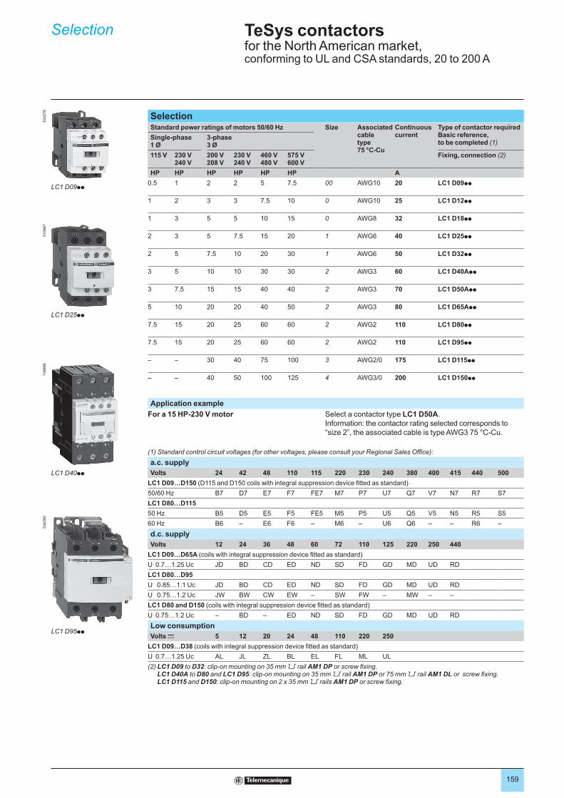
159
SelectionStandard power ratings of motors 50/60 Hz Size Associated
cable type 75 °C-Cu
Continuous current
Type of contactor required Basic reference, to be completed (1)
Single-phase 1 Ø
3-phase 3 Ø
115 V 230 V 240 V
200 V 208 V
230 V 240 V
460 V 480 V
575 V 600 V
Fixing, connection (2)
HP HP HP HP HP HP A
0.5 1 2 2 5 7.5 00 AWG10 20 LC1 D09pp
1 2 3 3 7.5 10 0 AWG10 25 LC1 D12pp
1 3 5 5 10 15 0 AWG8 32 LC1 D18pp
2 3 5 7.5 15 20 1 AWG6 40 LC1 D25pp
2 5 7.5 10 20 30 1 AWG6 50 LC1 D32pp
3 5 10 10 30 30 2 AWG3 60 LC1 D40App
3 7.5 15 15 40 40 2 AWG3 70 LC1 D50App
5 10 20 20 40 50 2 AWG3 80 LC1 D65App
7.5 15 20 25 60 60 2 AWG2 110 LC1 D80pp
7.5 15 20 25 60 60 2 AWG2 110 LC1 D95pp
– – 30 40 75 100 3 AWG2/0 175 LC1 D115pp
– – 40 50 100 125 4 AWG3/0 200 LC1 D150pp
Application example
For a 15 HP-230 V motor Select a contactor type LC1 D50A.
Information: the contactor rating selected corresponds to
“size 2”, the associated cable is type AWG3 75 °C-Cu.
(1) Standard control circuit voltages (for other voltages, please consult your Regional Sales Office):
a.c. supply
Volts 24 42 48 110 115 220 230 240 380 400 415 440 500
LC1 D09…D150 (D115 and D150 coils with integral suppression device fitted as standard)
50/60 Hz B7 D7 E7 F7 FE7 M7 P7 U7 Q7 V7 N7 R7 S7
LC1 D80…D115
50 Hz B5 D5 E5 F5 FE5 M5 P5 U5 Q5 V5 N5 R5 S5
60 Hz B6 – E6 F6 – M6 – U6 Q6 – – R6 –
d.c. supply
Volts 12 24 36 48 60 72 110 125 220 250 440
LC1 D09…D65A (coils with integral suppression device fitted as standard)
U 0.7…1.25 Uc JD BD CD ED ND SD FD GD MD UD RD
LC1 D80…D95
U 0.85…1.1 Uc JD BD CD ED ND SD FD GD MD UD RD
U 0.75…1.2 Uc JW BW CW EW – SW FW – MW – –
LC1 D80 and D150 (coils with integral suppression device fitted as standard)
U 0.75…1.2 Uc – BD – ED ND SD FD GD MD UD RD
Low consumption
Volts c 5 12 20 24 48 110 220 250
LC1 D09…D38 (coils with integral suppression device fitted as standard)
U 0.7…1.25 Uc AL JL ZL BL EL FL ML UL
(2) LC1 D09 to D32: clip-on mounting on 35 mm 6 rail AM1 DP or screw fixing. LC1 D40A to D80 and LC1 D95: clip-on mounting on 35 mm 6 rail AM1 DP or 75 mm 6 rail AM1 DL or screw fixing. LC1 D115 and D150: clip-on mounting on 2 x 35 mm 6 rails AM1 DP or screw fixing.
Selection TeSys contactorsfor the North American market,conforming to UL and CSA standards, 20 to 200 A
LC1 D09pp
534278
LC1 D25pp
510667
LC1 D40pp
106896
LC1 D95pp
534280
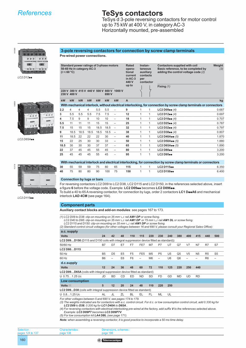
160
3-pole reversing contactors for connection by screw clamp terminalsPre-wired power connections.
Standard power ratings of 3-phase motors 50-60 Hz in category AC-3(θ y 60 °C)
Rated opera-tional current in AC-3 440 Vup to
Instan- taneous auxiliary contactspercontactor
Contactors supplied with coilBasic reference, to be completed by adding the control voltage code (2)
Weight (3)
Fixing (1)
220 V 230 V
380 V400 V
415 V 440 V 500 V 660 V 690 V
1000 V
kW kW kW kW kW kW kW A kg
With mechanical interlock, without electrical interlocking, for connection by screw clamp terminals or connectors
2.2 4 4 4 5.5 5.5 – 9 1 1 LC2 D09pp (4) 0.687
3 5.5 5.5 5.5 7.5 7.5 – 12 1 1 LC2 D12pp (4) 0.697
4 7.5 9 9 10 10 – 18 1 1 LC2 D18pp (4) 0.707
5.5 11 11 11 15 15 – 25 1 1 LC2 D25pp (4) 0.787
7.5 15 15 15 18.5 18.5 – 32 1 1 LC2 D32pp (4) 0.797
9 18.5 18.5 18.5 18.5 18.5 – 38 1 1 LC2 D38pp (4) 0.807
11 18.5 22 22 22 30 – 40 1 1 LC2 D40App (5) 1.870
15 22 25 30 30 33 – 50 1 1 LC2 D50App (5) 1.880
18.5 30 30 30 37 37 – 65 1 1 LC2 D65App (5) 1.890
22 37 45 45 55 45 – 80 1 1 LC2 D80pp 3.200
25 45 45 45 55 45 – 95 1 1 LC2 D95pp 3.200
With mechanical interlock and electrical interlocking, for connection by screw clamp terminals or connectors
30 55 59 59 75 80 65 115 1 1 LC2 D115pp 6.350
40 75 80 80 90 100 75 150 1 1 LC2 D150pp 6.400
Connection by lugs or bars
For reversing contactors LC2 D09 to LC2 D38, LC2 D115 and LC2 D150, in the references selected above, insert
a figure 6 before the voltage code. Example: LC2 D09pp becomes LC2 D096pp.
To build a 40 to 65 A reversing contactor, for connection by lugs, order 2 contactors LC1 DppA6 and mechanical
interlock LAD 4CM (see page 164).
Component partsAuxiliary contact blocks and add-on modules: see pages 167 to 173.
(1) LC2 D09 to D38: clip-on mounting on 35 mm 5 rail AM1 DP or screw fixing. LC2 D40 to D95: clip-on mounting on 35 mm 5 rail AM1 DP or 75 mm 5 rail AM1 DL or screw fixing. LC2 D115 and D150: clip-on mounting on 35 mm 5 rail AM1 DP or screw fixing.
(2) Standard control circuit voltages (for other voltages between 16 and 690 V, please consult your Regional Sales Office):
a.c. supply
Volts 24 42 48 110 115 220 230 240 380 400 415 440 500
LC2 D09…D150 (D115 and D150 coils with integral suppression device fitted as standard))
50/60 Hz B7 D7 E7 F7 FE7 M7 P7 U7 Q7 V7 N7 R7 S7
LC2 D80…D115
50 Hz B5 D5 E5 F5 FE5 M5 P5 U5 Q5 V5 N5 R5 S5
60 Hz B6 – E6 F6 – M6 – U6 Q6 – – R6 –
d.c.supply
Volts 12 24 36 48 60 72 110 125 220 250 440
LC2 D09…D65A (coils with integral suppression device fitted as standard)
U 0.75…1.25 Uc JD BD CD ED ND SD FD GD MD UD RD
Low consumption
Volts c 5 12 20 24 48 110 220 250
LC2 D09...D38 (coils with integral suppression device fitted as standard)
U 0.8…1.25 Uc AL JL ZL BL EL FL ML UL
For other voltages between 5 and 690 V, see pages 174 to 179.(3) The weights indicated are for contactors with a.c. control circuit. For d.c. or low consumption control circuit, add 0.330 kg for
LC2 D09 to D38, 0.200 kg for LC1 D40A to D65A..(4) For reversing contactors with electrical interlocking pre-wired at the factory, add suffix V to the references selected above.
Example: LC2 D09P7 becomes LC2 D09P7V.(5) For low consumption kit LA4 DBL (see page 171).
Note: when assembling a reversing contactor, it is good practice to incorporate a 50 ms time delay.
References TeSys contactorsTeSys d 3-pole reversing contactors for motor control up to 75 kW at 400 V, in category AC-3 Horizontally mounted, pre-assembled
Selection : pages 124 to 137
Characteristics : page 138
Dimensions, schemes : page 186
LC2 D12pp
810369
LC2 D65App
106905
LC2 D115pp
113119
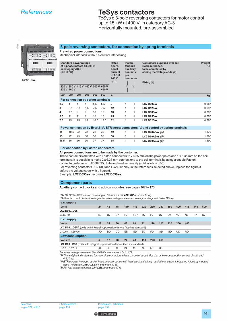
161
References TeSys contactorsTeSys d 3-pole reversing contactors for motor control up to 15 kW at 400 V, in category AC-3 Horizontally mounted, pre-assembled
Selection : pages 124 to 137
Characteristics : page 138
Dimensions, schemes : page 186
3-pole reversing contactors, for connection by spring terminalsPre-wired power connections.Mechanical interlock without electrical interlocking.
Standard power ratings of 3-phase motors 50-60 Hz in category AC-3(θ y 60 °C)
Rated opera-tional current in AC-3 440 Vup to
Instan-taneous auxiliary contactspercontactor
Contactors supplied with coilBasic reference, to be completed by adding the voltage code (2)
Weight (3)
Fixing (1)
220 V 230 V
380 V400 V
415 V 440 V 500 V 660 V 690 V
kW kW kW kW kW kW A kg
For connection by spring terminals
2.2 4 4 4 5.5 5.5 9 1 1 LC2 D093pp 0.687
3 5.5 5.5 5.5 7.5 7.5 12 1 1 LC2 D123pp 0.697
4 7.5 9 9 10 10 18 1 1 LC2 D183pp 0.707
5.5 11 11 11 15 15 25 1 1 LC2 D253pp 0.787
7.5 15 15 15 18.5 18.5 32 1 1 LC2 D323pp 0.797
Power connection by EverLink®, BTR screw connectors (4) and control by spring terminals
11 18.5 22 22 22 30 40 1 1 LC2 D40A3pp (5) 1.870
15 22 25 30 30 33 50 1 1 LC2 D50A3pp (5) 1.880
18.5 30 30 30 37 37 65 1 1 LC2 D60A3pp (5) 1.890
For connection by Faston connectors
All power connections are to be made by the customer.These contactors are fitted with Faston connectors: 2 x 6.35 mm on the power poles and 1 x 6.35 mm on the coil
terminals. It is possible to make 2 x 6.35 mm connections to the coil terminals by using a double Faston
connector, reference: LAD 99635, to be ordered separately (sold in lots of 100).
For reversing contactors LC2 D09 and LC2 D12 only, in the references selected above, replace the figure 3
before the voltage code with a figure 9.
Example: LC2 D093pp becomes LC2 D099pp.
Component partsAuxiliary contact blocks and add-on modules: see pages 167 to 173.
(1) LC2 D09 to D32: clip-on mounting on 35 mm 5 rail AM1 DP or screw fixing.(2) Standard control circuit voltages (for other voltages, please consult your Regional Sales Office):
a.c. supply
Volts 24 42 48 110 115 220 230 240 380 400 415 440 500
LC2 D09…D65
50/60 Hz B7 D7 E7 F7 FE7 M7 P7 U7 Q7 V7 N7 R7 S7
d.c. supply
Volts 12 24 36 48 60 72 110 125 220 250 440
LC2 D09…D65A (coils with integral suppression device fitted as standard)
U 0.75…1.25 Uc JD BD CD ED ND SD FD GD MD UD RD
Low consumption
Volts c 5 12 20 24 48 110 220 250
LC2 D09...D32 (coils with integral suppression device fitted as standard)
U 0.8…1.25 Uc AL JL ZL BL EL FL ML UL
For other voltages between 5 and 690 V, see pages 174 to 179.(3) The weights indicated are for reversing contactors with a.c. control circuit. For d.c. or low consumption control circuit, add
0.330 kg.(4) BTR screws: hexagon socket head. In accordance with local electrical wiring regulations, a size 4 insulated Allen key must be
used (reference LAD ALLEN4, see page 173).(5) For low consumption kit LA4 DBL (see page 171).
LC2 D123pp
565133
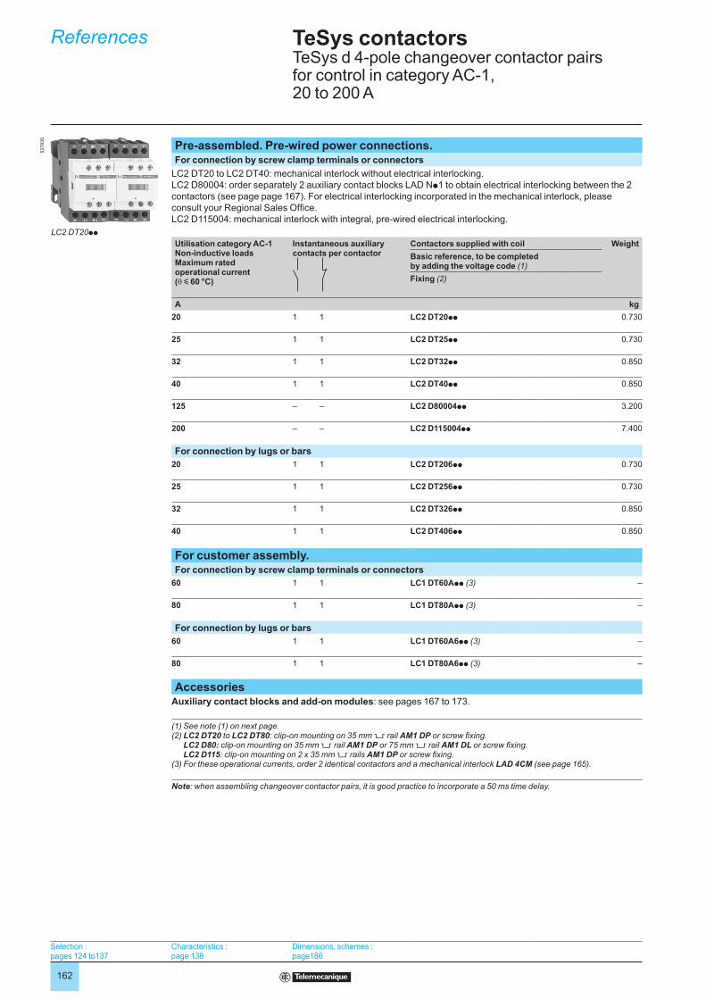
162
Pre-assembled. Pre-wired power connections.For connection by screw clamp terminals or connectors
LC2 DT20 to LC2 DT40: mechanical interlock without electrical interlocking.
LC2 D80004: order separately 2 auxiliary contact blocks LAD Np1 to obtain electrical interlocking between the 2
contactors (see page page 167). For electrical interlocking incorporated in the mechanical interlock, please
consult your Regional Sales Office.
LC2 D115004: mechanical interlock with integral, pre-wired electrical interlocking.
Utilisation category AC-1Non-inductive loadsMaximum rated operational current(θ y 60 °C)
Instantaneous auxiliary contacts per contactor
Contactors supplied with coil Weight
Basic reference, to be completed by adding the voltage code (1)
Fixing (2)
A kg
20 1 1 LC2 DT20pp 0.730
25 1 1 LC2 DT25pp 0.730
32 1 1 LC2 DT32pp 0.850
40 1 1 LC2 DT40pp 0.850
125 – – LC2 D80004pp 3.200
200 – – LC2 D115004pp 7.400
For connection by lugs or bars
20 1 1 LC2 DT206pp 0.730
25 1 1 LC2 DT256pp 0.730
32 1 1 LC2 DT326pp 0.850
40 1 1 LC2 DT406pp 0.850
For customer assembly.For connection by screw clamp terminals or connectors
60 1 1 LC1 DT60App (3) –
80 1 1 LC1 DT80App (3) –
For connection by lugs or bars
60 1 1 LC1 DT60A6pp (3) –
80 1 1 LC1 DT80A6pp (3) –
AccessoriesAuxiliary contact blocks and add-on modules: see pages 167 to 173.
(1) See note (1) on next page.(2) LC2 DT20 to LC2 DT80: clip-on mounting on 35 mm 5 rail AM1 DP or screw fixing.
LC2 D80: clip-on mounting on 35 mm 5 rail AM1 DP or 75 mm 5 rail AM1 DL or screw fixing. LC2 D115: clip-on mounting on 2 x 35 mm 5 rails AM1 DP or screw fixing.
(3) For these operational currents, order 2 identical contactors and a mechanical interlock LAD 4CM (see page 165).
Note: when assembling changeover contactor pairs, it is good practice to incorporate a 50 ms time delay.
References TeSys contactorsTeSys d 4-pole changeover contactor pairs for control in category AC-1, 20 to 200 A
LC2 DT20pp
537835
Selection : pages 124 to137
Characteristics : page 138
Dimensions, schemes : page186

163
Pre-assembled. Pre-wired power connections.For connection by spring terminals.
Utilisation category AC-1Non-inductive loadsMaximum rated operational current(θ y 60 °C)
Instantaneous auxiliary contacts per contactor
Contactors supplied with coil Weight
Basic reference, to be completed by adding the control voltage code (1)
Fixing (2)
A kg
20 1 1 LC2 DT203pp 0.760
For customer assembly.Power connection by EverLink®, BTR screw connectors (3) and control by spring terminals
60 1 1 LC1 DT60A3pp (4) –
80 1 1 LC1 DT80A3pp (4) –
Separate componentsAuxiliary contact blocks and add-on modules: see pages 167 to 173.
(1) Standard control circuit voltages (for other voltages, please consult your Regional Sales Office):
a.c. supply
Volts 24 42 48 110 115 220 230 240 380 400 415 440 500
LC2 DT20…DT40, LC1 DT60…DT80
50/60 Hz B7 D7 E7 F7 FE7 M7 P7 U7 Q7 V7 N7 R7 –
LC2 D80004…D115004
50 Hz B5 D5 E5 F5 FE5 M5 P5 U5 Q5 V5 N5 R5 S5
60 Hz B6 – E6 F6 – M6 – U6 Q6 – – R6 –
d.c. supply
Volts 12 24 36 48 60 72 110 125 220 250 440
LC2 DT20…DT40, LC1 DT60…DT80 (coils with integral suppression device fitted as standard)
U 0.7…1.25 Uc JD BD CD ED ND SD FD GD MD UD RD
Low consumption
Volts c 5 12 20 24 48 110 220 250
LC2 DT20...DT40 (coils with integral suppression device fitted as standard)
U 0.7…1.25 Uc AL JL ZL BL EL FL ML UL
For other voltages between 5 and 690 V, see pages 174 to 179(2) Clip-on mounting on 35 mm 5 rail AM1 DP or screw fixing.(3) BTR screws: hexagon socket head. In accordance with local electrical wiring regulations, a size 4 insulated Allen key must be
used (reference LAD ALLEN4, see page 173).(4) For these operational currents, order 2 identical contactors and a mechanical interlock LAD 4CM (see page 165).
References TeSys contactorsTeSys d 4-pole changeover contactor pairs for control in category AC-1, 20 A
Selection : pages 124 to137
Characteristics : page 138
Dimensions, schemes : page186
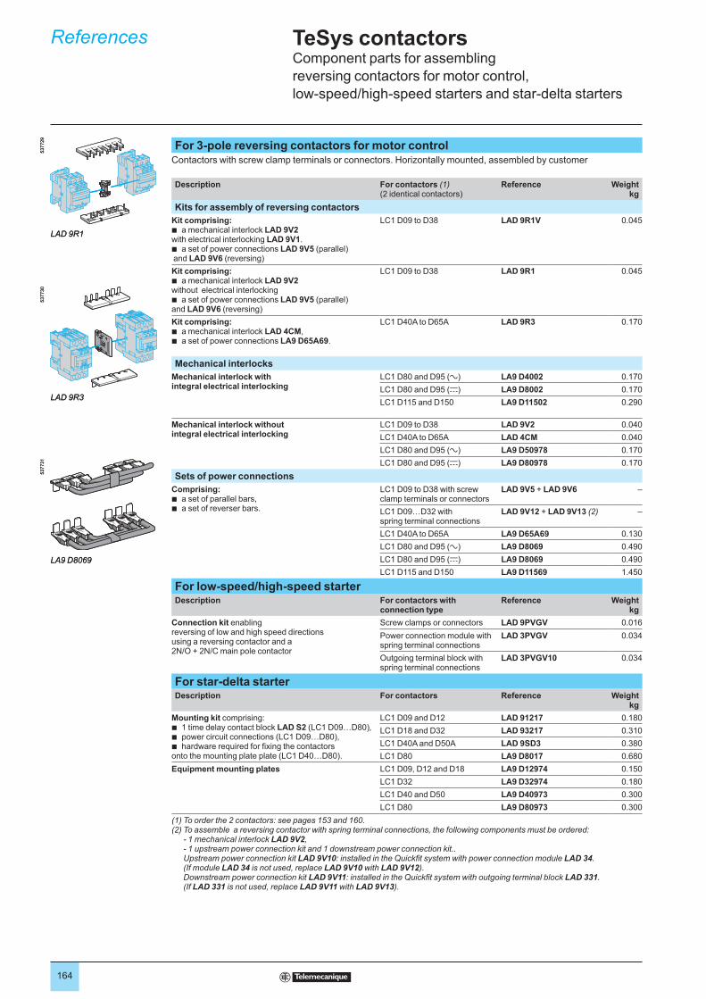
164
For 3-pole reversing contactors for motor controlContactors with screw clamp terminals or connectors. Horizontally mounted, assembled by customer
Description For contactors (1)(2 identical contactors)
Reference Weightkg
Kits for assembly of reversing contactors
Kit comprising:a mechanical interlock LAD 9V2
with electrical interlocking LAD 9V1.a set of power connections LAD 9V5 (parallel)
and LAD 9V6 (reversing)
b
b
LC1 D09 to D38 LAD 9R1V 0.045
Kit comprising: a mechanical interlock LAD 9V2
without electrical interlocking a set of power connections LAD 9V5 (parallel)
and LAD 9V6 (reversing)
b
b
LC1 D09 to D38 LAD 9R1 0.045
Kit comprising: a mechanical interlock LAD 4CM,a set of power connections LA9 D65A69.
bb
LC1 D40A to D65A LAD 9R3 0.170
Mechanical interlocks
Mechanical interlock with integral electrical interlocking
LC1 D80 and D95 (a) LA9 D4002 0.170
LC1 D80 and D95 (c) LA9 D8002 0.170
LC1 D115 and D150 LA9 D11502 0.290
Mechanical interlock without integral electrical interlocking
LC1 D09 to D38 LAD 9V2 0.040
LC1 D40A to D65A LAD 4CM 0.040
LC1 D80 and D95 (a) LA9 D50978 0.170
LC1 D80 and D95 (c) LA9 D80978 0.170
Sets of power connections
Comprising: a set of parallel bars,a set of reverser bars.
bb
LC1 D09 to D38 with screw clamp terminals or connectors
LAD 9V5 + LAD 9V6 –
LC1 D09…D32 with spring terminal connections
LAD 9V12 + LAD 9V13 (2) –
LC1 D40A to D65A LA9 D65A69 0.130
LC1 D80 and D95 (a) LA9 D8069 0.490
LC1 D80 and D95 (c) LA9 D8069 0.490
LC1 D115 and D150 LA9 D11569 1.450
For low-speed/high-speed starterDescription For contactors with
connection typeReference Weight
kg
Connection kit enablingreversing of low and high speed directions using a reversing contactor and a 2N/O + 2N/C main pole contactor
Screw clamps or connectors LAD 9PVGV 0.016
Power connection module with spring terminal connections
LAD 3PVGV 0.034
Outgoing terminal block with spring terminal connections
LAD 3PVGV10 0.034
For star-delta starterDescription For contactors Reference Weight
kg
Mounting kit comprising:1 time delay contact block LAD S2 (LC1 D09…D80),power circuit connections (LC1 D09…D80), hardware required for fixing the contactors
onto the mounting plate plate (LC1 D40…D80).
bbb
LC1 D09 and D12 LAD 91217 0.180
LC1 D18 and D32 LAD 93217 0.310
LC1 D40A and D50A LAD 9SD3 0.380
LC1 D80 LA9 D8017 0.680
Equipment mounting plates LC1 D09, D12 and D18 LA9 D12974 0.150
LC1 D32 LA9 D32974 0.180
LC1 D40 and D50 LA9 D40973 0.300
LC1 D80 LA9 D80973 0.300
(1) To order the 2 contactors: see pages 153 and 160.(2) To assemble a reversing contactor with spring terminal connections, the following components must be ordered:
- 1 mechanical interlock LAD 9V2, - 1 upstream power connection kit and 1 downstream power connection kit.. Upstream power connection kit LAD 9V10: installed in the Quickfit system with power connection module LAD 34. (If module LAD 34 is not used, replace LAD 9V10 with LAD 9V12). Downstream power connection kit LAD 9V11: installed in the Quickfit system with outgoing terminal block LAD 331. (If LAD 331 is not used, replace LAD 9V11 with LAD 9V13).
537729
LAD 9R1
537729
LAD 9R1
LAD 9R3
537730
LAD 9R3
537730
LA9 D8069
537731
LA9 D8069
537731
References TeSys contactorsComponent parts for assembling
reversing contactors for motor control,
low-speed/high-speed starters and star-delta starters

165
For 4-pole changeover contactor pairs (3-phase distribution + neutral)
Contactors with screw clamp terminals or connectors. Horizontally mounted, assembled by customer..
Description For contactors (1)(2 identical contactors)
Reference Weightkg
Kits for assembly of changeover contactor pairs
Kit comprising:a mechanical interlock LAD 9V2
with electrical interlocking LAD 9V,a set of power connections (changeover) LAD 9V71.
b
b
LC1 DT20 to DT40 with screw clamps or connectors
LAD T9R1V 0.045
Kit comprising:a mechanical interlock LAD 9V2
without electrical interlocking,a set of power connections (changeover) LAD 9V7.
b
b
LC1 DT20 to DT40 with screw clamps or connectors
LAD T9R1 0.045
Mechanical interlocks
With integral electrical interlocking
LC1 D65004 LA9 D4002 0.170
LC1 D80004 LA9 D4002 0.170
LP1 D80004 LA9 D8002 0.170
LC1 D115004 LA9 D11502 0.280
Without integral electrical interlocking
LC1 DT20 to DT40 with screw clamps or connectors
LAD 9V2 (2) 0.040
LC1 DT203 to DT403 with spring terminals
LAD 9V2 (2) 0.040
LC1 DT60A and DT80A LAD 4CM 0.040
LC1 D80004 LA9 D50978 0.155
LP1 D80004 LA9 D80978 0.180
Sets of power connections
Comprising a set of parallel bars
LC1 D65004 LA9 D6570 0.150
LC1 D80004 LA9 D8070 0.280
LP1 D80004 LA9 D8070 0.280
LC1 D115004 LA9 D11570 1.100
LC1 DT203 to DT403 with spring terminals
LAD 9V9 0.100
LC1 D80004 LA9 D8070 (2) –
LP1 D80004 LA9 D8070 (2) –
For 3-pole changeover contactor pairsContactors with screw clamp terminals or connectors. Horizontally mounted, assembled by customer.
Description For contactors (1)(2 identical contactors)
Reference Weightkg
Mechanical interlocks
Without integral electrical interlocking
LC1 D40A…D65A LAD 9R3S 0.105
With integral electrical interlocking
LC1 D115 and D150 LA9 D11502 0.280
Sets of power connections
Comprising a set of parallel bars, LC1 D115 and D150 LA9 D11571 0.960
(1) To order the 2 contactors: see pages 153 and 160.(2) Order 2 contact blocks LAD Np1 to build the electrical interlock, see page 167.
LA9 D4002
537732
LA9 D4002
537732
LA9 D50978
537733
LA9 D50978
537733
LA9 D8070
537735
LA9 D8070
537735
LA9 D6570
537734
LA9 D6570
537734
References TeSys contactorsComponent parts for assembling
changeover contactor pairs
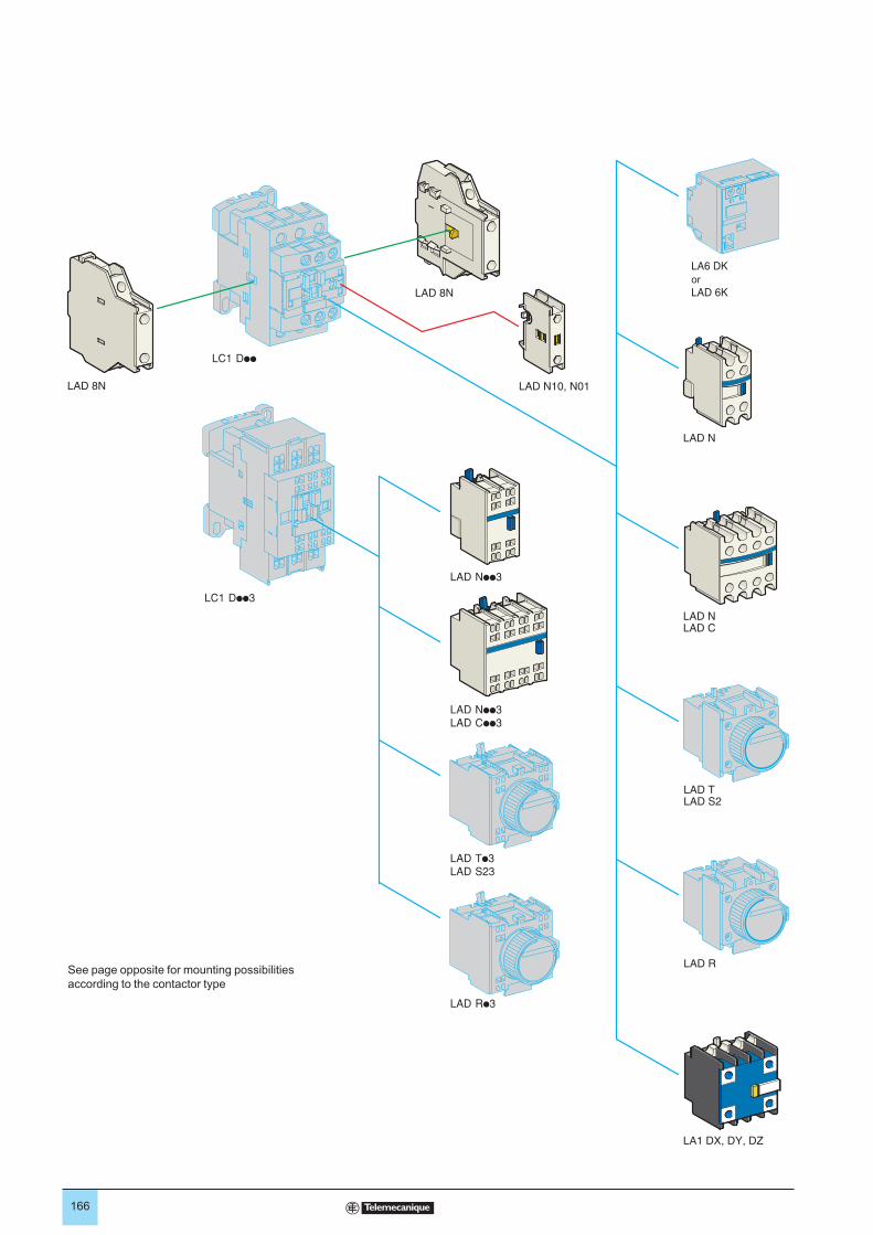
166
See page opposite for mounting possibilities
according to the contactor type
or
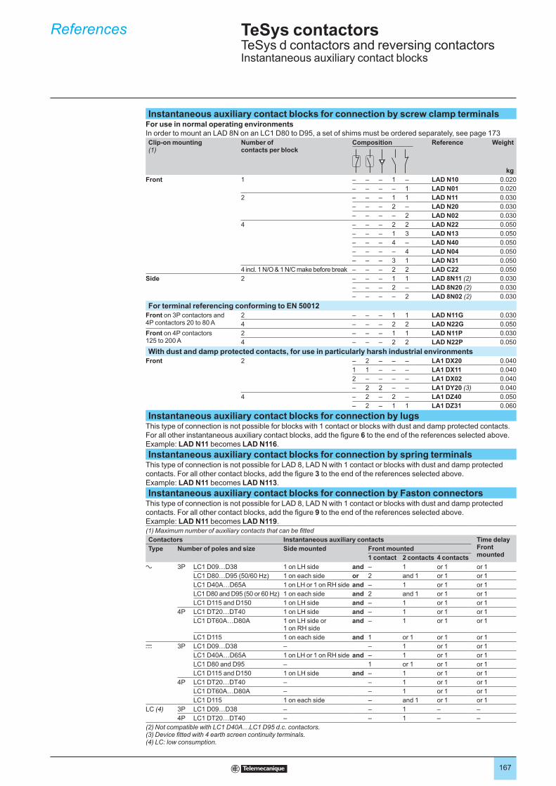
167
Instantaneous auxiliary contact blocks for connection by screw clamp terminalsFor use in normal operating environmentsIn order to mount an LAD 8N on an LC1 D80 to D95, a set of shims must be ordered separately, see page 173
Clip-on mounting(1)
Number of contacts per block
Composition Reference Weight
kg
Front 1 – – – 1 – LAD N10 0.020
– – – – 1 LAD N01 0.020
2 – – – 1 1 LAD N11 0.030
– – – 2 – LAD N20 0.030
– – – – 2 LAD N02 0.030
4 – – – 2 2 LAD N22 0.050
– – – 1 3 LAD N13 0.050
– – – 4 – LAD N40 0.050
– – – – 4 LAD N04 0.050
– – – 3 1 LAD N31 0.050
4 incl. 1 N/O & 1 N/C make before break – – – 2 2 LAD C22 0.050
Side 2 – – – 1 1 LAD 8N11 (2) 0.030
– – – 2 – LAD 8N20 (2) 0.030
– – – – 2 LAD 8N02 (2) 0.030
For terminal referencing conforming to EN 50012
Front on 3P contactors and 4P contactors 20 to 80 A
2 – – – 1 1 LAD N11G 0.030
4 – – – 2 2 LAD N22G 0.050
Front on 4P contactors125 to 200 A
2 – – – 1 1 LAD N11P 0.030
4 – – – 2 2 LAD N22P 0.050
With dust and damp protected contacts, for use in particularly harsh industrial environments
Front 2 – 2 – – – LA1 DX20 0.040
1 1 – – – LA1 DX11 0.040
2 – – – – LA1 DX02 0.040
– 2 2 – – LA1 DY20 (3) 0.040
4 – 2 – 2 – LA1 DZ40 0.050
– 2 – 1 1 LA1 DZ31 0.060
Instantaneous auxiliary contact blocks for connection by lugsThis type of connection is not possible for blocks with 1 contact or blocks with dust and damp protected contacts.
For all other instantaneous auxiliary contact blocks, add the figure 6 to the end of the references selected above.
Example: LAD N11 becomes LAD N116.
Instantaneous auxiliary contact blocks for connection by spring terminalsThis type of connection is not possible for LAD 8, LAD N with 1 contact or blocks with dust and damp protected
contacts. For all other contact blocks, add the figure 3 to the end of the references selected above.
Example: LAD N11 becomes LAD N113.
Instantaneous auxiliary contact blocks for connection by Faston connectorsThis type of connection is not possible for LAD 8, LAD N with 1 contact or blocks with dust and damp protected
contacts. For all other contact blocks, add the figure 9 to the end of the references selected above.
Example: LAD N11 becomes LAD N119.
(1) Maximum number of auxiliary contacts that can be fitted
Contactors Instantaneous auxiliary contacts Time delayFront mounted
Type Number of poles and size Side mounted Front mounted
1 contact 2 contacts 4 contacts
a 3P LC1 D09…D38 1 on LH side and – 1 or 1 or 1
LC1 D80…D95 (50/60 Hz) 1 on each side or 2 and 1 or 1 or 1
LC1 D40A…D65A 1 on LH or 1 on RH side and – 1 or 1 or 1
LC1 D80 and D95 (50 or 60 Hz) 1 on each side and 2 and 1 or 1 or 1
LC1 D115 and D150 1 on LH side and – 1 or 1 or 1
4P LC1 DT20…DT40 1 on LH side and – 1 or 1 or 1
LC1 DT60A…D80A 1 on LH side or 1 on RH side
and – 1 or 1 or 1
LC1 D115 1 on each side and 1 or 1 or 1 or 1
c 3P LC1 D09…D38 – – 1 or 1 or 1
LC1 D40A…D65A 1 on LH or 1 on RH side and – 1 or 1 or 1
LC1 D80 and D95 – 1 or 1 or 1 or 1
LC1 D115 and D150 1 on LH side and – 1 or 1 or 1
4P LC1 DT20…DT40 – – 1 or 1 or 1
LC1 DT60A…D80A – – 1 or 1 or 1
LC1 D115 1 on each side – and 1 or 1 or 1
LC (4) 3P LC1 D09…D38 – – 1 – –
4P LC1 DT20…DT40 – – 1 – –
(2) Not compatible with LC1 D40A…LC1 D95 d.c. contactors.(3) Device fitted with 4 earth screen continuity terminals.(4) LC: low consumption.
References TeSys contactorsTeSys d contactors and reversing contactorsInstantaneous auxiliary contact blocks
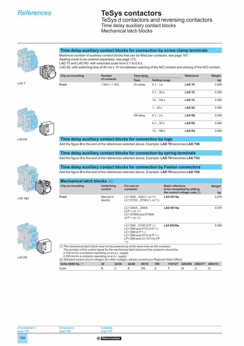
168
Time delay auxiliary contact blocks for connection by screw clamp terminalsMaximum number of auxiliary contact blocks that can be fitted per contactor, see page 167.
Sealing cover to be ordered separately, see page 173.
LAD T0 and LAD R0: with extended scale from 0.1 to 0.6 s.
LAD S2: with switching time of 40 ms ± 15 ms between opening of the N/C contact and closing of the N/O contact.
Clip-on mounting Number of contacts
Time delay Reference Weight
kgType Setting range
Front 1 N/O + 1 N/C On-delay 0.1…3 s LAD T0 0.060
0.1…30 s LAD T2 0.060
10…180 s LAD T4 0.060
1…30 s LAD S2 0.060
Off-delay 0.1…3 s LAD R0 0.060
0.1…30 s LAD R2 0.060
10…180 s LAD R4 0.060
Time delay auxiliary contact blocks for connection by lugsAdd the figure 6 to the end of the references selected above. Example: LAD T0 becomes LAD T06.
Time delay auxiliary contact blocks for connection by spring terminalsAdd the figure 3 to the end of the references selected above. Example: LAD T0 becomes LAD T03
Time delay auxiliary contact blocks for connection by Faston connectorsAdd the figure 9 to the end of the references selected above. Example: LAD T0 becomes LAD T09.
Mechanical latch blocks (1)
Clip-on mounting Unlatching control
For use on contactor
Basic reference, to be completed by adding the control voltage code (2)
Weight
kg
Front Manual or electric
LC1 D09…D38 (a or c)LC1 DT20…DT40 (a or c)
LAD 6K10p 0.070
LC1 D40A…D65A (3 P a or c)LC1 DT60A and DT80A(4 P a or c)
LAD 6K10p 0.070
LC1 D80…D150 (3 P a)LC1 D80 and D115 (3 P c)LC1 D80 (4 P a)LC1 D80 and D115 (4 P a)LP1 D80 and LC1 D115( 4 P c)
LA6 DK20p 0.090
(1) The mechanical latch block must not be powered up at the same time as the contactor. The duration of the control signal for the mechanical latch block and the contactor should be: u 100 ms for a contactor operating on an a.c. supply, u 250 ms for a contactor operating on a d.c. supply.
(2) Standard control circuit voltages (for other voltages, please consult your Regional Sales Office).
Volts 50/60 Hz, c 24 32/36 42/48 60/72 100 110/127 220/240 256/277 380/415
Code B C E EN K F M U Q
References TeSys contactorsTeSys d contactors and reversing contactorsTime delay auxiliary contact blocksMechanical latch blocks
LAD T
LA6 DK
LAD Tp3
LA6 DK
Characteristics:page 144
Dimensions:page 180
Schemes:page 184
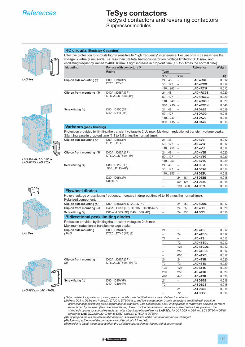
169
RC circuits (Resistor-Capacitor)
Effective protection for circuits highly sensitive to "high frequency" interference. For use only in cases where the
voltage is virtually sinusoidal. i.e. less than 5% total harmonic distortion. Voltage limited to 3 Uc max. and
oscillating frequency limited to 400 Hz max. Slight increase in drop-out time (1.2 to 2 times the normal time).
Mounting For use with contactor (1) Reference Weight
kg
Rating Type
V a V c
Clip-on side mounting (3) D09…D38 (3P)DT20…DT40
24…48 – LAD 4RCE 0.012
50…127 – LAD 4RCG 0.012
110…240 – LAD 4RCU 0.012
Clip-on front mounting (3) D40A…D65A (3P)DT60A…DT80A (4P)
24…48 – LAD 4RC3E 0.020
50…127 – LAD 4RC3G 0.020
110…240 – LAD 4RC3U 0.020
380…415 – LAD 4RC3N 0.040
Screw fixing (4) D80…D150 (3P)D40…D115 (4P)
24…48 – LA4 DA2E 0.018
50…127 – LA4 DA2G 0.018
110…240 – LA4 DA2U 0.018
380…415 – LA4 DA2N 0.018
Varistors (peak limiting)
Protection provided by limiting the transient voltage to 2 Uc max. Maximum reduction of transient voltage peaks.
Slight increase in drop-out time (1.1 to 1.5 times the normal time).
Clip-on side mounting (3) D09…D38 (3P)DT20…DT40
24…48 – LAD 4VE 0.012
50…127 – LAD 4VG 0.012
110…250 – LAD 4VU 0.012
Clip-on front mounting (3) D40A…D65A (3P)DT60A…DT80A (4P)
24…48 – LAD 4V3E 0.020
50…127 – LAD 4V3G 0.020
110…250 – LAD 4V3U 0.020
Screw fixing (4) D80…D115 (3P) D80…D115 (4P)
24…48 – LA4 DE2E 0.018
50…127 – LA4 DE2G 0.018
110…250 – LA4 DE2U 0.018
D80…D95 (3P)D80 (4P)
– 24…48 LA4 DE3E 0.018
– 50…127 LA4 DE3G 0.018
– 110…250 LA4 DE3U 0.018
Flywheel diodesNo overvoltage or oscillating frequency. Increase in drop-out time (6 to 10 times the normal time).
Polarised component.
Clip-on side mounting (5) D09…D38 (3P). DT20…DT40 – 24…250 LAD 4DDL 0.012
Clip-on front mounting (5) D40A…D65A (3P). DT60A…DT80A (4P) – 24…250 LAD 4D3U 0.020
Screw fixing (4) D80 and D95 (3P). D40…D80 (4P) – 24…250 LA4 DC3U 0.018
Bidirectional peak limiting diodesProtection provided by limiting the transient voltage to 2 Uc max.
Maximum reduction of transient voltage peaks.
Clip-on side mounting (3) (5)
D09…D38 (3P)DT20…DT40 (4P) (2)
24 – LAD 4TB 0.012
– 24 LAD 4TBDL 0.012
72 – LAD 4TS 0.012
– 72 LAD 4TSDL 0.012
– 125 LAD 4TGDL 0.012
– 250 LAD 4TUDL 0.012
– 600 LAD 4TXDL 0.012
Clip-on front mounting(3)
D40A…D65A (3P)DT60A…DT80A (4P) (2)
24 24 LAD 4T3B 0.020
72 72 LAD 4T3S 0.020
125 125 LAD 4T3G 0.020
250 250 LAD 4T3U 0.020
440 440 LAD 4T3R 0.020
Screw fixing (4) D80…D95 (3P)D40…D80 (4P)
24 – LA4 DB2B 0.018
72 – LA4 DB2S 0.018
– 24 LA4 DB3B 0.018
– 72 LA4 DB3S 0.018
(1) For satisfactory protection, a suppressor module must be fitted across the coil of each contactor.(2) From D09 to D65A and from LC1 DT20 to DT80A, d.c. and low consumption 3-pole contactors are fitted with a built-in
bidirectional peak limiting diode suppressor as standard. This bidirectional peak limiting diode is removable and can therefore be replaced by the user. (See reference above). If a d.c. or low consumption contactor is used without suppression. the standard suppressor should be replaced with a blanking plug (reference LAD 9DL for LC1 D09 to D38 and LC1 DT20 to DT40; reference LAD 9DL3 for LC1 D40A to D65A and LC1 DT60A to DT80A).
(3) Clipping-on makes the electrical connection. The overall size of the contactor remains unchanged.(4) Mounting at the top of the contactor on coil terminals A1 and A2.(5) In order to install these accessories, the existing suppression device must first be removed.
References TeSys contactorsTeSys d contactors and reversing contactorsSuppressor modules
LAD 4pp
LAD 4RC3p, LAD 4V3p,LAD 4D3U, LAD 4T3p
LA4 Dpp
LAD 4DDL or LAD 4TpDL

170
See page opposite for mounting possibilities
according to the contactor type
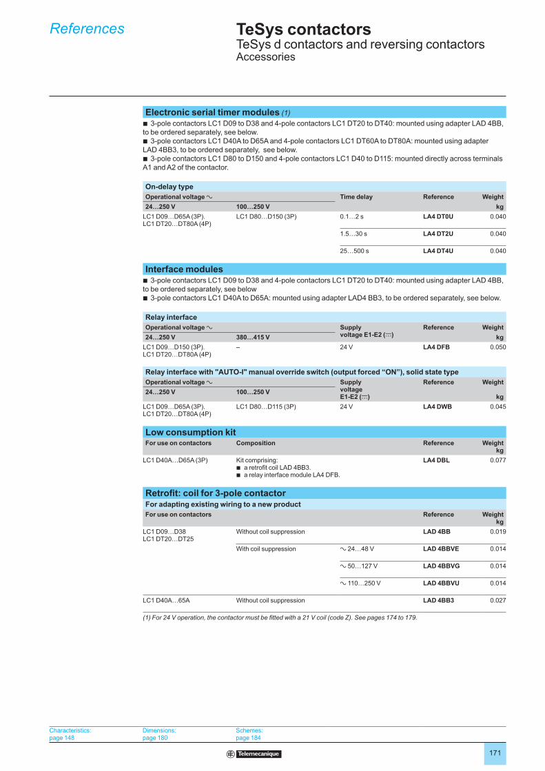
171
Electronic serial timer modules (1)
3-pole contactors LC1 D09 to D38 and 4-pole contactors LC1 DT20 to DT40: mounted using adapter LAD 4BB,
to be ordered separately, see below.
3-pole contactors LC1 D40A to D65A and 4-pole contactors LC1 DT60A to DT80A: mounted using adapter
LAD 4BB3, to be ordered separately, see below.
3-pole contactors LC1 D80 to D150 and 4-pole contactors LC1 D40 to D115: mounted directly across terminals
A1 and A2 of the contactor.
b
b
b
On-delay type
Operational voltage a Time delay Reference Weight
kg24…250 V 100…250 V
LC1 D09…D65A (3P).LC1 DT20…DT80A (4P)
LC1 D80…D150 (3P) 0.1…2 s LA4 DT0U 0.040
1.5…30 s LA4 DT2U 0.040
25…500 s LA4 DT4U 0.040
Interface modules3-pole contactors LC1 D09 to D38 and 4-pole contactors LC1 DT20 to DT40: mounted using adapter LAD 4BB,
to be ordered separately, see below
3-pole contactors LC1 D40A to D65A: mounted using adapter LAD4 BB3, to be ordered separately, see below.
b
b
Relay interface
Operational voltage a Supply voltage E1-E2 (c)
Reference Weight
kg24…250 V 380…415 V
LC1 D09…D150 (3P).LC1 DT20…DT80A (4P)
– 24 V LA4 DFB 0.050
Relay interface with "AUTO-I" manual override switch (output forced “ON”), solid state type
Operational voltage a Supply voltage E1-E2 (c)
Reference Weight
kg24…250 V 100…250 V
LC1 D09…D65A (3P).LC1 DT20…DT80A (4P)
LC1 D80…D115 (3P) 24 V LA4 DWB 0.045
Low consumption kitFor use on contactors Composition Reference Weight
kg
LC1 D40A…D65A (3P) Kit comprising:a retrofit coil LAD 4BB3.a relay interface module LA4 DFB.
bb
LA4 DBL 0.077
Retrofit: coil for 3-pole contactorFor adapting existing wiring to a new product
For use on contactors Reference Weightkg
LC1 D09…D38LC1 DT20…DT25
Without coil suppression LAD 4BB 0.019
With coil suppression a 24…48 V LAD 4BBVE 0.014
a 50…127 V LAD 4BBVG 0.014
a 110…250 V LAD 4BBVU 0.014
LC1 D40A…65A Without coil suppression LAD 4BB3 0.027
(1) For 24 V operation, the contactor must be fitted with a 21 V coil (code Z). See pages 174 to 179.
References TeSys contactorsTeSys d contactors and reversing contactorsAccessories
Characteristics:page 148
Dimensions:page 180
Schemes:page 184
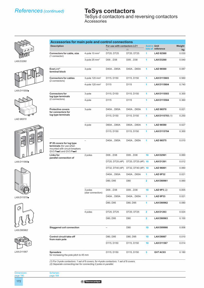
172
Accessories for main pole and control connectionsDescription For use with contactors LC1 Sold in
lots ofUnit reference
Weight
kga c
Connectors for cable, size (1 connector)
4-pole 10 mm2 DT20, DT25 DT20, DT25 1 LAD 92560 0.030
3-pole 25 mm2 D09…D38 D09…D38 1 LA9 D3260 0.040
EverLink®
terminal block3-pole D40A…D65A D40A…D65A 1 LAD 96560 0.087
Connectors for cables (2 connectors)
3-pole 120 mm2 D115, D150 D115, D150 1 LA9 D115603 0.560
4-pole 120 mm2 D115 D115 1 LA9 D115604 0.740
Connectors for lug type terminals (2 connectors)
3-pole D115, D150 D115, D150 1 LA9 D115503 0.300
4-pole D115 D115 1 LA9 D115504 0.360
Protective coversfor connectors for lug type terminals
3-pole D40A…D65A D40A…D65A 1 LAD 96570 0.021
D115, D150 D115, D150 1 LA9 D115703 (1) 0.250
4-pole D60A…D80A D60A…D80A 1 LAD 96580 0.027
D115, D150 D115, D150 1 LA9 D115704 0.300
IP 20 covers for lug type terminals (for use when mounted with circuit-breakers GV3 Ppp6 and GV3 Ppp6
– D40A…D65A D40A…D65A 1 LAD 96575 0.010
Links for parallel connection of
2 poles D09…D38 D09…D38 10 LA9 D2561 0.060
DT20, DT25 (4P) DT20, DT25 (4P) 10 LA9 D1261 0.012
DT32, DT40 (4P) DT32, DT40 (4P) 10 LAD 96061 0.060
D40A…D65A D40A…D65A 1 LAD 9P32 0.021
D80, D95 D80 2 LA9 D80961 0.060
3 poles (star connection)
D09…D38 D09…D38 10 LAD 9P3 (2) 0.005
D40A…D65A D40A…D65A 1 LAD 9P33 0.021
D80, D95 D80, D95 1 LA9 D80962 0.080
4 poles DT20, DT25 DT20, DT25 2 LA9 D1263 0.024
D80, D95 D80 2 LA9 D80963 0.100
Staggered coil connection – D80 10 LA9 D09966 0.006
Control circuit take-off from main pole
D80, D95 D80, D95 10 LA9 D8067 0.010
D115, D150 D115, D150 10 LA9 D11567 0.014
Spreaders for increasing the pole pitch to 45 mm
D115, D150 D115, D150 3 GV7 AC03 0.180
(1) For 3-pole contactors: 1 set of 6 covers, for 4-pole contactors: 1 set of 8 covers.(2) Separate connecting bar for connecting 2 poles in parallel.
References (continued) TeSys contactorsTeSys d contactors and reversing contactorsAccessories
LA9 D3260
LA9 D11550p
LAD 96570
LA9 D11560p
LA9 D11570p
LA9 D80962
LA9 D11567
Dimensions:page 180
Schemes:page 184

173
Sets of contacts and arc chambersDescription For contactor Reference Weight
kg
Sets of contacts 3-pole LC1 D115 LA5 D1158031 0.260
LC1 D150 LA5 D150803 0.260
4-pole LC1 D115004 LA5 D115804 0.330
Arc chambers 3-pole LC1 D115 LA5 D11550 0.395
LC1 D150 LA5 D15050 0.395
4-pole LC1 D115004 LA5 D115450 0.470
Power connection accessoriesTerminal block For supply to one or more GV2 G busbar sets GV1 G09 0.040
Set of 63 A busbars for parallelling of contactors
2 contactors LC1 D09…D18 or D25…D38 GV2 G245 0.036
4 contactors LC1 D09…D18 or D25…D38 GV2 G445 0.077
Set of 115 A busbars for parallelling of contactors
2 contactors LC1 D40A…D65A GV3 G264 0.150
3 contactors LC1 D40A…D65A GV3 G364 (1) 0.250
Set of S-shape busbars For circuit-breakers GV3 Ppp and GV3 Lpp and contactors LC1 D40A…D65A
GV3 S 0.104
Protection accessoriesDescription Use Sold in
lots ofReference Weight
kg
Miniature control circuit fuse holder
5 x 20 with 4 A-250 V fuse 1 LA9 D941 0.025
Sealing cover For LAD T, LAD R 1 LA9 D901 0.005
Safety cover preventing access to the moving contact carrier
LC1 D09…D65A and DT20…DT80A 1 LAD 9ET1 0.026
LC1 D80 and D95 1 LAD 9ET3 0.004
LC1 D115 and D150 1 LAD 9ET4 0.004
Marking accessoriesDescription Use Sold in
lots ofUnit reference
Weightkg
Sheet of 64 blank legends, self-adhesive, 8 x 33 mm (2)
Contactors (except 4P) LC1 D80…D115 , LAD N (4 contacts), LA6 DK
10 LAD 21 0.020
Sheet of 112 blank legends, self-adhesive, 8 x 12 mm (2)
LAD N (2 contacts), LAD T, LAD R, LRD
10 LAD 22 0.020
Sheet of 64 blank legends for marking using plotter or 8 x 33 mm engraver
Contactors (except 4P) LC1 D80…D115, LAD (4 contacts), LA6 DK
10 LAD 23 0.050
Sheet of 440 blank legends for marking using plotter or 8 x 12 mm engraver
All products 35 LAD 24 0.200
Marker holder snap-in, 8 x 22 mm
4-pole contactors, LC1 D80...D115, LA6 DK
100 LA9 D92 0.001
Marker holder snap-in, 8 x 18 mm
LC1 D09...D65A, LC1 DT20...DT80A,LAD N (4 contacts), LAD T, LAD R
100 LAD 90 0.001
Bag of 300 blank legends self-adhesive, 7 x 21 mm
On holder LA9 D92 1 LA9 D93 0.001
“SIS Label” labelling softwaresupplied on CD-Rom
Multi-language version: English, French, German, Italian, Spanish
1 XBY 2U 0.100
Mounting accessoriesRetrofit plate for screw fixing
For replacement of LC1 D40 to D65 with LC1 D40A to D65A
1 LAD 7X3 0.150
Mounting plate For replacement of LC1 F115 or F150 with LC1 D115 or D150
1 LA9 D730 0.360
Set of shims For fitting side mounting blocks LAD 8N on LC1 D80 and D95
1 LA9 D511 0.020
Size 4 Allen key, insulated, 1000 V
For use on contactors LC1 D40A to LC1 D150
5 LAD ALLEN4 0.026
(1) With this set of busbars, any one contactor can be supplied directly by its EverLink® double cage power terminal block. The other two contactors are supplied by the busbar set. The 115 A limitation is therefore applied to these two contactors. Example: 1 LC1 D65A supplied directly + 1 contactor LC1 D65A and 1 contactor LC1 D50 A supplied via the busbar set = 115 A. This combination is compatible with busbar set GV3 G364.
(2) These legends are for sticking onto the safety cover of the contactors or add-on block, if fitted.
References (continued) TeSys contactorsTeSys d contactors and reversing contactorsAccessories
GV2 G245
GV1 G09
LA9 D941
GV3 S
LAD 9ETp
LAD 7X3
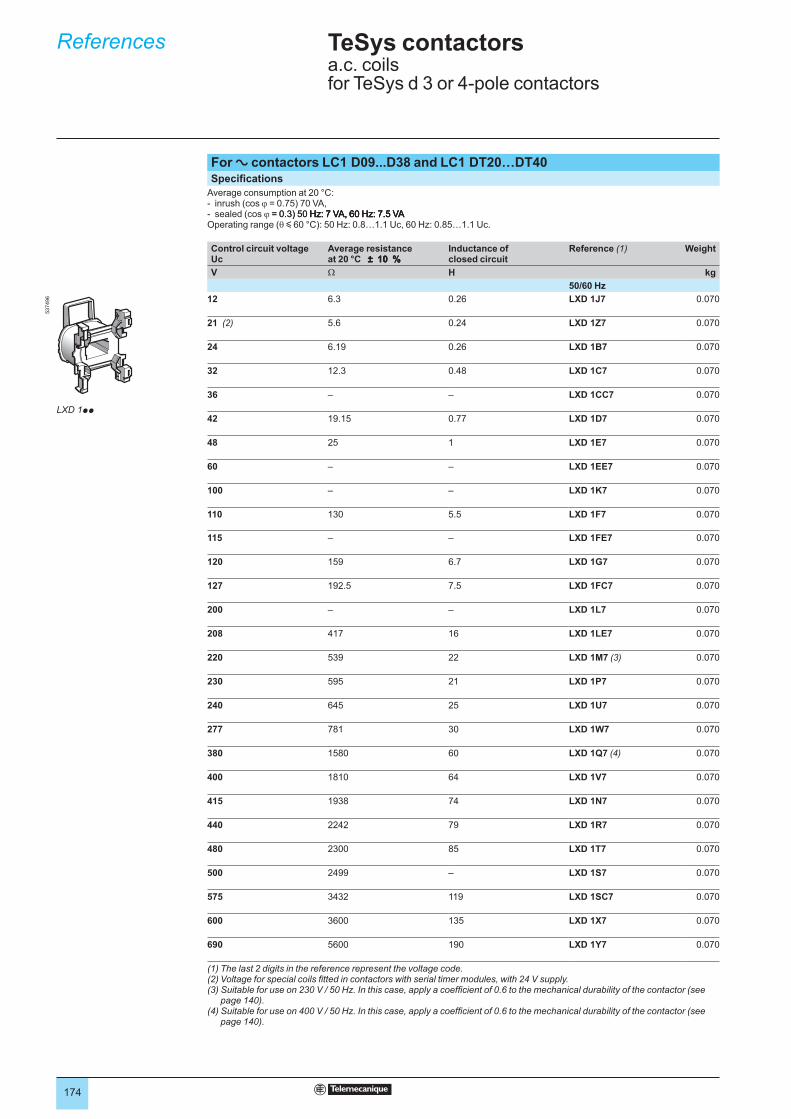
174
TeSys contactors 5 a.c. coils for TeSys d 3 or 4-pole contactors
References 5
For a contactors LC1 D09...D38 and LC1 DT20…DT40Specifications
Average consumption at 20 °C:inrush (cos ϕ = 0.75) 70 VA,sealed (cos ϕ = 0.3) 50 Hz: 7 VA, 60 Hz: 7.5 VA= 0.3) 50 Hz: 7 VA, 60 Hz: 7.5 VA Hz: 7 VA, 60 Hz: 7.5 VAHz: 7 VA, 60 Hz: 7.5 VA
Operating range (θ y 60 °C): 50 Hz: 0.8…1.1 Uc, 60 Hz: 0.85…1.1 Uc.
--
Control circuit voltage Uc
Average resistance at 20 °C ± 10 % ± 10 % ± 10 %
Inductance of closed circuit
Reference (1) Weight
V Ω H kg
50/60 Hz
12 6.3 0.26 LXD 1J7 0.070
21 (2) 5.6 0.24 LXD 1Z7 0.070
24 6.19 0.26 LXD 1B7 0.070
32 12.3 0.48 LXD 1C7 0.070
36 – – LXD 1CC7 0.070
42 19.15 0.77 LXD 1D7 0.070
48 25 1 LXD 1E7 0.070
60 – – LXD 1EE7 0.070
100 – – LXD 1K7 0.070
110 130 5.5 LXD 1F7 0.070
115 – – LXD 1FE7 0.070
120 159 6.7 LXD 1G7 0.070
127 192.5 7.5 LXD 1FC7 0.070
200 – – LXD 1L7 0.070
208 417 16 LXD 1LE7 0.070
220 539 22 LXD 1M7 (3) 0.070
230 595 21 LXD 1P7 0.070
240 645 25 LXD 1U7 0.070
277 781 30 LXD 1W7 0.070
380 1580 60 LXD 1Q7 (4) 0.070
400 1810 64 LXD 1V7 0.070
415 1938 74 LXD 1N7 0.070
440 2242 79 LXD 1R7 0.070
480 2300 85 LXD 1T7 0.070
500 2499 – LXD 1S7 0.070
575 3432 119 LXD 1SC7 0.070
600 3600 135 LXD 1X7 0.070
690 5600 190 LXD 1Y7 0.070
(1) The last 2 digits in the reference represent the voltage code.(2) Voltage for special coils fitted in contactors with serial timer modules, with 24 V supply.(3) Suitable for use on 230 V / 50 Hz. In this case, apply a coefficient of 0.6 to the mechanical durability of the contactor (see
page 140).(4) Suitable for use on 400 V / 50 Hz. In this case, apply a coefficient of 0.6 to the mechanical durability of the contactor (see
page 140).
537496
LXD 1pp
537496
LXD 1pp
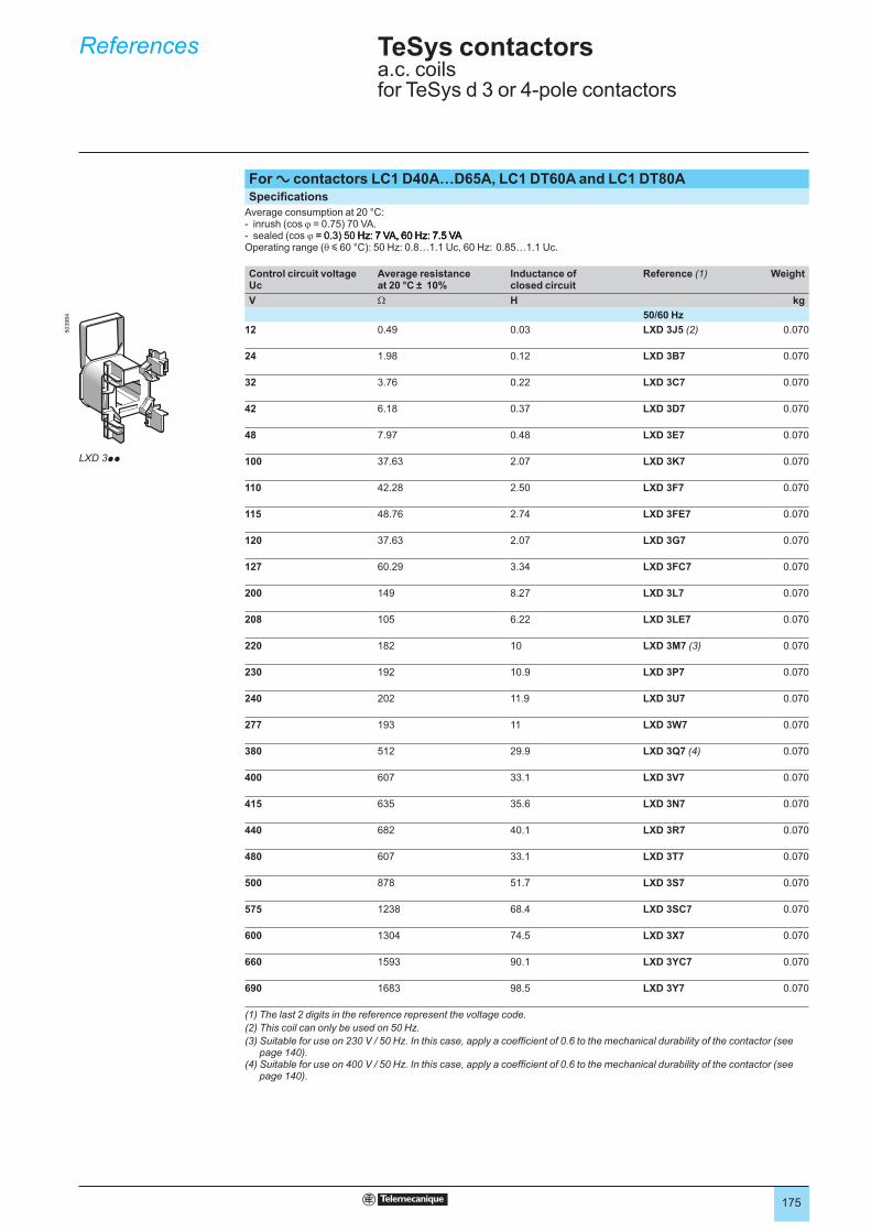
175
TeSys contactors 5 a.c. coils for TeSys d 3 or 4-pole contactors
References 5 503984
LXD 3pp
For a contactors LC1 D40A…D65A, LC1 DT60A and LC1 DT80ASpecifications
Average consumption at 20 °C:inrush (cos ϕ = 0.75) 70 VA.sealed (cos ϕ = 0.3) 50 Hz: 7 VA, 60 Hz: 7.5 VA= 0.3) 50 Hz: 7 VA, 60 Hz: 7.5 VA Hz: 7 VA, 60 Hz: 7.5 VAHz: 7 VA, 60 Hz: 7.5 VA
Operating range (θ y 60 °C): 50 Hz: 0.8…1.1 Uc, 60 Hz: 0.85…1.1 Uc.
--
Control circuit voltage Uc
Average resistance at 20 °C ± 10%
Inductance of closed circuit
Reference (1) Weight
V Ω H kg
50/60 Hz
12 0.49 0.03 LXD 3J5 (2) 0.070
24 1.98 0.12 LXD 3B7 0.070
32 3.76 0.22 LXD 3C7 0.070
42 6.18 0.37 LXD 3D7 0.070
48 7.97 0.48 LXD 3E7 0.070
100 37.63 2.07 LXD 3K7 0.070
110 42.28 2.50 LXD 3F7 0.070
115 48.76 2.74 LXD 3FE7 0.070
120 37.63 2.07 LXD 3G7 0.070
127 60.29 3.34 LXD 3FC7 0.070
200 149 8.27 LXD 3L7 0.070
208 105 6.22 LXD 3LE7 0.070
220 182 10 LXD 3M7 (3) 0.070
230 192 10.9 LXD 3P7 0.070
240 202 11.9 LXD 3U7 0.070
277 193 11 LXD 3W7 0.070
380 512 29.9 LXD 3Q7 (4) 0.070
400 607 33.1 LXD 3V7 0.070
415 635 35.6 LXD 3N7 0.070
440 682 40.1 LXD 3R7 0.070
480 607 33.1 LXD 3T7 0.070
500 878 51.7 LXD 3S7 0.070
575 1238 68.4 LXD 3SC7 0.070
600 1304 74.5 LXD 3X7 0.070
660 1593 90.1 LXD 3YC7 0.070
690 1683 98.5 LXD 3Y7 0.070
(1) The last 2 digits in the reference represent the voltage code.
(2) This coil can only be used on 50 Hz.
(3) Suitable for use on 230 V / 50 Hz. In this case, apply a coefficient of 0.6 to the mechanical durability of the contactor (see page 140).
(4) Suitable for use on 400 V / 50 Hz. In this case, apply a coefficient of 0.6 to the mechanical durability of the contactor (see page 140).
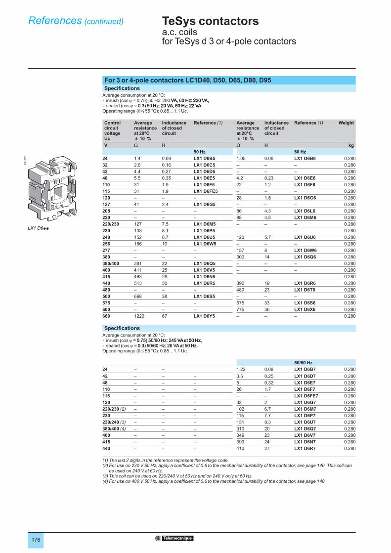
176
TeSys contactors 5 a.c. coils for TeSys d 3 or 4-pole contactors
References (continued) 5
For 3 or 4-pole contactors LC1D40, D50, D65, D80, D95Specifications
Average consumption at 20 °C:inrush (cos ϕ = 0.75) 50 Hz: 200 VA, 60 Hz: 220 VA, VA, 60 Hz: 220 VA,VA, 60 Hz: 220 VA,sealed (cos ϕ = 0.3) 50 Hz: 20 VA, 60 Hz: 22 VA= 0.3) 50 Hz: 20 VA, 60 Hz: 22 VA Hz: 20 VA, 60 Hz: 22 VAHz: 20 VA, 60 Hz: 22 VA
Operating range (θ y 55 °C): 0.85…1.1 Uc.
--
Control circuit voltage Uc
Average resistance at 20°C ± 10 %
Inductance of closed circuit
Reference (1) Average resistance at 20°C ± 10 %
Inductance of closed circuit
Reference (1) Weight
V Ω H Ω H kg
50 Hz 60 Hz
24 1.4 0.09 LX1 D6B5 1.05 0.06 LX1 D6B6 0.280
32 2.6 0.16 LX1 D6C5 – – – 0.280
42 4.4 0.27 LX1 D6D5 – – – 0.280
48 5.5 0.35 LX1 D6E5 4.2 0.23 LX1 D6E6 0.280
110 31 1.9 LX1 D6F5 22 1.2 LX1 D6F6 0.280
115 31 1.9 LX1 D6FE5 – – – 0.280
120 – – – 28 1.5 LX1 D6G6 0.280
127 41 2.4 LX1 D6G5 – – – 0.280
208 – – – 86 4.3 LX1 D6L6 0.280
220 – – – 98 4.8 LX1 D6M6 0.280
220/230 127 7.5 LX1 D6M5 – – – 0.280
230 133 8.1 LX1 D6P5 – – – 0.280
240 152 8.7 LX1 D6U5 120 5.7 LX1 D6U6 0.280
256 166 10 LX1 D6W5 – – – 0.280
277 – – – 157 8 LX1 D6W6 0.280
380 – – – 300 14 LX1 D6Q6 0.280
380/400 381 22 LX1 D6Q5 – – – 0.280
400 411 25 LX1 D6V5 – – – 0.280
415 463 26 LX1 D6N5 – – – 0.280
440 513 30 LX1 D6R5 392 19 LX1 D6R6 0.280
480 – – – 480 23 LX1 D6T6 0.280
500 668 38 LX1 D6S5 – – – 0.280
575 – – – 675 33 LX1 D6S6 0.280
600 – – – 775 36 LX1 D6X6 0.280
660 1220 67 LX1 D6Y5 – – – 0.280
Specifications
Average consumption at 20 °C:inrush (cos ϕ = 0.75) 50/60 Hz: 245 VA at 50 Hz,= 0.75) 50/60 Hz: 245 VA at 50 Hz, VA at 50 Hz,VA at 50 Hz,sealed (cos ϕ = 0.3) 50/60 Hz: 26 VA at 50 Hz.= 0.3) 50/60 Hz: 26 VA at 50 Hz.
Operating range (θ ≤ 55 °C): 0.85…1.1 Uc.
--
50/60 Hz
24 – ––
1.22 0.08 LX1 D6B7 0.280
42 – – – 3.5 0.25 LX1 D6D7 0.280
48 – – – 5 0.32 LX1 D6E7 0.280
110 – – – 26 1.7 LX1 D6F7 0.280
115 – – – – – LX1 D6FE7 0.280
120 – – – 32 2 LX1 D6G7 0.280
220/230 (2) – – – 102 6.7 LX1 D6M7 0.280
230 – – – 115 7.7 LX1 D6P7 0.280
230/240 (3) – – – 131 8.3 LX1 D6U7 0.280
380/400 (4) – – – 310 20 LX1 D6Q7 0.280
400 – – – 349 23 LX1 D6V7 0.280
415 – – – 390 24 LX1 D6N7 0.280
440 – – – 410 27 LX1 D6R7 0.280
(1) The last 2 digits in the reference represent the voltage code.(2) For use on 230 V 50 Hz, apply a coefficient of 0.6 to the mechanical durability of the contactor, see page 140 .This coil can
be used on 240 V at 60 Hz.(3) This coil can be used on 220/240 V at 50 Hz and on 240 V only at 60 Hz.(4) For use on 400 V 50 Hz, apply a coefficient of 0.6 to the mechanical durability of the contactor, see page 140.
537497
LX1 D6pp
537497
LX1 D6pp
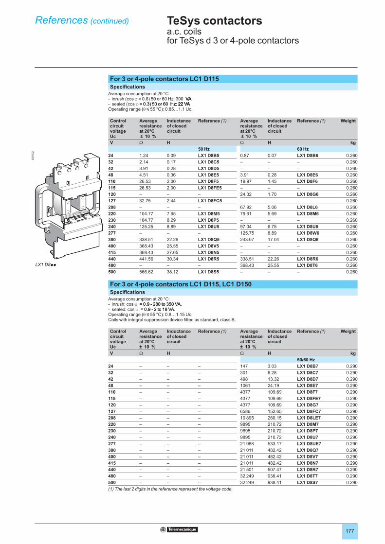
177
TeSys contactors 5 a.c. coils for TeSys d 3 or 4-pole contactors
References (continued) 5
For 3 or 4-pole contactors LC1 D115Specifications
Average consumption at 20 °C:inrush (cos ϕ = 0.8) 50 or 60 Hz: 300 VA, VA,VA,sealed (cos ϕ = 0.3) 50 or 60 Hz: 22 VA= 0.3) 50 or 60 Hz: 22 VA Hz: 22 VAHz: 22 VA
Operating range (θ y 55 °C): 0.85…1.1 Uc.
--
Control circuit voltage Uc
Average resistance at 20°C ± 10 %
Inductance of closed circuit
Reference (1) Average resistance at 20°C ± 10 %
Inductance of closed circuit
Reference (1) Weight
V Ω H Ω H kg
50 Hz 60 Hz
24 1.24 0.09 LX1 D8B5 0.87 0.07 LX1 D8B6 0.260
32 2.14 0.17 LX1 D8C5 – – – 0.260
42 3.91 0.28 LX1 D8D5 – – – 0.260
48 4.51 0.36 LX1 D8E5 3.91 0.28 LX1 D8E6 0.260
110 26.53 2.00 LX1 D8F5 19.97 1.45 LX1 D8F6 0.260
115 26.53 2.00 LX1 D8FE5 – – – 0.260
120 – – – 24.02 1.70 LX1 D8G6 0.260
127 32.75 2.44 LX1 D8FC5 – – – 0.260
208 – – – 67.92 5.06 LX1 D8L6 0.260
220 104.77 7.65 LX1 D8M5 79.61 5.69 LX1 D8M6 0.260
230 104.77 8.29 LX1 D8P5 – – – 0.260
240 125.25 8.89 LX1 D8U5 97.04 6.75 LX1 D8U6 0.260
277 – – – 125.75 8.89 LX1 D8W6 0.260
380 338.51 22.26 LX1 D8Q5 243.07 17.04 LX1 D8Q6 0.260
400 368.43 25.55 LX1 D8V5 – – – 0.260
415 368.43 27.65 LX1 D8N5 – – – 0.260
440 441.56 30.34 LX1 D8R5 338.51 22.26 LX1 D8R6 0.260
480 – – – 368.43 25.55 LX1 D8T6 0.260
500 566.62 38.12 LX1 D8S5 – – – 0.260
For 3 or 4-pole contactors LC1 D115, LC1 D150Specifications
Average consumption at 20 °C:inrush: cos ϕ = 0.9 - 280 to 350 VA,= 0.9 - 280 to 350 VA,sealed: cos ϕ = 0.9 - 2 to 18 VA.= 0.9 - 2 to 18 VA.
Operating range (θ y 55 °C): 0.8…1.15 Uc. Coils with integral suppression device fitted as standard, class B.
--
Control circuit voltage Uc
Average resistance at 20°C ± 10 %
Inductance of closed circuit
Reference (1) Average resistance at 20°C ± 10 %
Inductance of closed circuit
Reference (1) Weight
V Ω H Ω H kg
50/60 Hz
24 – – – 147 3.03 LX1 D8B7 0.290
32 – – – 301 8.28 LX1 D8C7 0.290
42 – – – 498 13.32 LX1 D8D7 0.290
48 – – – 1061 24.19 LX1 D8E7 0.290
110 – – – 4377 109.69 LX1 D8F7 0.290
115 – – – 4377 109.69 LX1 D8FE7 0.290
120 – – – 4377 109.69 LX1 D8G7 0.290
127 – – – 6586 152.65 LX1 D8FC7 0.290
208 – – – 10 895 260.15 LX1 D8LE7 0.290
220 – – – 9895 210.72 LX1 D8M7 0.290
230 – – – 9895 210.72 LX1 D8P7 0.290
240 – – – 9895 210.72 LX1 D8U7 0.290
277 – – – 21 988 533.17 LX1 D8UE7 0.290
380 – – – 21 011 482.42 LX1 D8Q7 0.290
400 – – – 21 011 482.42 LX1 D8V7 0.290
415 – – – 21 011 482.42 LX1 D8N7 0.290
440 – – – 21 501 507.47 LX1 D8R7 0.290
480 – – – 32 249 938.41 LX1 D8T7 0.290
500 – – – 32 249 938.41 LX1 D8S7 0.290
(1) The last 2 digits in the reference represent the voltage code.
LX1 D8pp
537502
LX1 D8pp
537502
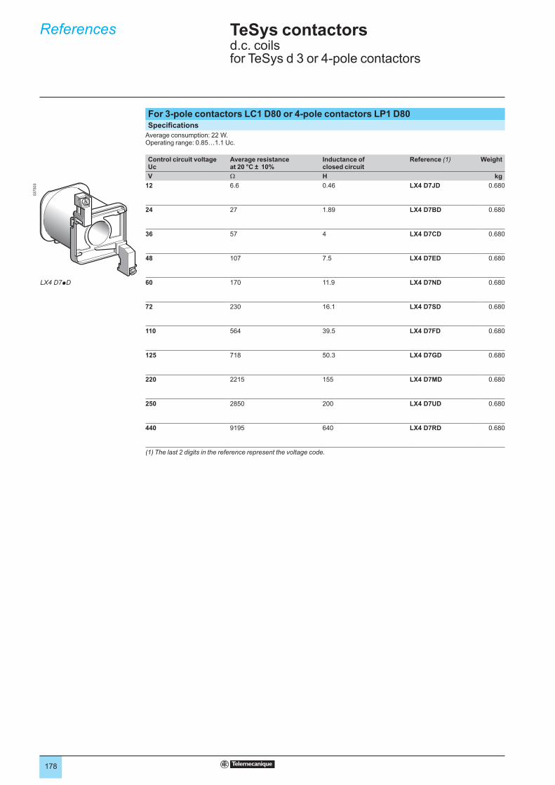
178
TeSys contactors 5 d.c. coils for TeSys d 3 or 4-pole contactors
References 5
For 3-pole contactors LC1 D80 or 4-pole contactors LP1 D80Specifications
Average consumption: 22 W.Operating range: 0.85…1.1 Uc.
Control circuit voltage Uc
Average resistance at 20 °C ± 10%
Inductance of closed circuit
Reference (1) Weight
V Ω H kg
12 6.6 0.46 LX4 D7JD 0.680
24 27 1.89 LX4 D7BD 0.680
36 57 4 LX4 D7CD 0.680
48 107 7.5 LX4 D7ED 0.680
60 170 11.9 LX4 D7ND 0.680
72 230 16.1 LX4 D7SD 0.680
110 564 39.5 LX4 D7FD 0.680
125 718 50.3 LX4 D7GD 0.680
220 2215 155 LX4 D7MD 0.680
250 2850 200 LX4 D7UD 0.680
440 9195 640 LX4 D7RD 0.680
(1) The last 2 digits in the reference represent the voltage code.
LX4 D7pD
537503
LX4 D7pD
537503

179
TeSys contactors 5 d.c. coils for TeSys d 3 or 4-pole contactors
References 5
For contactors LC1 D115, D150Specifications
Consumption: inrush 270 to 365 W, sealed 2.4 to 5.1 W.Operating range: 0.7…1.2 Uc.Coils with integral suppression device fitted as standard, class B.
Control circuit voltage Uc
Average resistance at 20 °C ± 10 % ± 10 % ± 10 %
Inductance of closed circuit
Reference (1) Weight
V Ω H kg
24 147 3.03 LX4 D8BD 0.300
48 1061 24.19 LX4 D8ED 0.300
60 1673 38.44 LX4 D8ND 0.300
72 2500 56.27 LX4 D8SD 0.300
110 4377 109.69 LX4 D8FD 0.300
125 6586 152.65 LX4 D8GD 0.300
220 9895 210.72 LX4 D8MD 0.300
250 18 022 345.40 LX4 D8UD 0.300
440 21 501 684.66 LX4 D8RD 0.300
For 3-pole contactors LC1 D80 or 4-pole contactors LP1 D80Specifications
Wide range coils for specific applications
Average consumption: 23 W.Operating range: 0.75 to 1.2 Uc.Coils with "TH" treatment as standard.
Control circuit voltage Uc
Average resistance at 20 °C ± 10 %
Inductance of closed circuit
Reference (1) Weight
V Ω H kg
12 6.2 0.49 LX4 D7JW 0.680
24 23.5 1.75 LX4 D7BW 0.680
36 51.9 4.18 LX4 D7CW 0.680
48 94.2 7 LX4 D7EW 0.680
72 204 15.7 LX4 D7SW 0.680
110 483 36 LX4 D7FW 0.680
220 1922 144 LX4 D7MW 0.680
(1) The last 2 digits in the reference represent the voltage code.
537504
LX4 D8pD
537504
LX4 D8pD

180
TeSys contactors 5 TeSys d contactorsControl circuit: a.c.
Dimensions 5
LC1 D09…D18 (3-pole) LC1 D25…D38 (3-pole), LC1 DT20…DT40 (4-pole)
LC1 D09…D18 D093…D123
D099…D129
D25…D38 D183…D323
DT20 and DT25
DT203 and DT253
DT32 and DT40
DT323 and DT403
b without add-on blocks 77 99 80 85 99 85 99 91 105
b1 with LAD 4BB 94 107 95,5 98 107 98 – – –
with LA4 Dp2 110 (1) 123 (1) 111,5 (1) 114 (1) 123 (1) 114 – – –
with LA4 DF, DT 119 (1) 132 (1) 120.5 (1) 123 (1) 132 (1) 129 – – –
with LA4 DW, DL 126 (1) 139 (1) 127.5 (1) 130 (1) 139 (1) 190 – – –
c without cover or add-on blocks 84 84 84 90 90 90 90 97 97
with cover, without add-on blocks 86 86 86 92 92 92 92 99 99
c1 with LAD N or C (2 or 4 contacts) 117 117 117 123 123 123 123 131 131
c2 with LA6 DK10, LAD 6K10 129 129 129 135 135 135 135 143 143
c3 with LAD T, R, S 137 137 137 143 143 143 143 151 151
with LAD T, R, S and sealing cover 141 141 141 147 147 147 147 155 155
(1) Including LAD 4BB.
LC1 D40A…D65A (3-pole), LC1 DT60A…DT80A (4-pole), LC1 D80 and D95 (3-pole), LC1 D80004 and D80008 (4-pole),
LC1 D65004, D40008 and D65008 (4-pole)
11
7
12
2
a(LAD 8N) (LAD 8N)
12,5c1
c2
c3
b1
12 c
12,5
Minimum electrical clearance
LC1 D40A…D65A DT60A…DT80A D40008 D80, D65004 D95, D65008 D80004 D80008
a 55 70 85 85 85 96 96
b1 with LA4 Dp2 – – 135 135 135 135 135
with LA4 DB3 or LAD 4BB3 136 – – 135 – – –
with LA4 DF, DT 157 – 142 142 142 142 142
with LA4 DM, DW, DL 166 – 150 150 150 150 150
c without cover or add-on blocks 118 118 125 125 125 125 140
with cover, without add-on blocks 120 120 – 130 130 – –
c1 with LAD N (1 contact) – – 139 150 150 150 150
with LAD N or C (2 or 4 contacts) 150 150 147 158 158 158 158
c2 with LAD 6K10 or LA6 DK 163 163 159 170 170 170 170
c3 with LAD T, R, S 171 171 167 178 178 178 178
with LAD T, R, S and sealing cover 175 175 171 182 182 182 182
LC1 D115 and D150 (3-pole), LC1 D115004 (4-pole)
LC1 D115, D150 D115004 D115006 D150006 D1150046
a 120 150 120 120 155
b1 with LA4 DA2 174 174 174 174 174
with LA4 DF, DT 185 185 185 185 185
with LA4 DM, DL 188 188 188 188 188
with LA4 DW 188 188 188 – 188
c without cover or add-on blocks 132 132 115 115 115
with cover, without add-on blocks 136 – – – –
c1 with LAD N or C (2 or 4 contacts) 150 150 150 150 150
c2 with LA6 DK20 155 155 155 155 155
c3 with LAD T, R, S 168 168 168 168 168
with LAD T, R, S and sealing cover 172 172 172 172 172
(LAD 8) (LAD 8) (1)
b
c10
c1
c2
c3
45 12,512,5
b1
44
LA4
(LAD 8) (LAD 8) (1)
b
c10
c1
c2
c3
45 12,512,5
b1
44
LA4
(LAD 8)
b
45 12,5(LAD 8) (1)
12,5
b1
44
LA4
c10
c1
c2
c3
Minimum electrical clearance
(LAD 8)
b
45 12,5(LAD 8) (1)
12,5
b1
44
LA4
c10
c1
c2
c3
Minimum electrical clearance
12,5(LAD 8) (LAD 8)
127 b
1
a 12,5
4432
LA4
c12
c1
c2
c3
Minimum electrical clearance
12,5(LAD 8) (LAD 8)
127 b
1
a 12,5
4432
LA4
c12
c1
c2
c3
Minimum electrical clearance
158
c a
c1
c2
c3
b1
LAD 8LA4
10
Min. electrical clearance
158
c a
c1
c2
c3
b1
LAD 8LA4
10
Min. electrical clearance
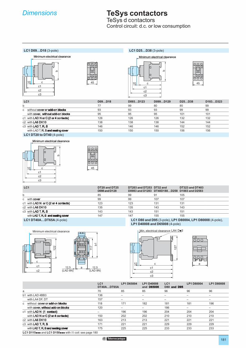
181
TeSys contactors 5 TeSys d contactorsControl circuit: d.c. or low consumption
Dimensions 5
LC1 D09…D18 (3-pole) LC1 D25…D38 (3-pole)
LC1 D09…D18 D093…D123 D099…D129 D25…D38 D183…D323
b 77 99 80 85 99
c without cover or add-on blocks cover or add-on blockscover or add-on blocks or add-on blocksor add-on blocks add-on blocksadd-on blocks 93 93 93 99 99
with cover, without add-on blocks cover, without add-on blockscover, without add-on blocks without add-on blockswithout add-on blocks 95 95 95 101 101
c1 with LAD N or C (2 or 4 contacts) LAD N or C (2 or 4 contacts)LAD N or C (2 or 4 contacts) or C (2 or 4 contacts)or C (2 or 4 contacts) C (2 or 4 contacts)C (2 or 4 contacts) 126 126 126 132 132
c2 with LA6 DK10 LA6 DK10LA6 DK10 138 138 138 144 144
c3 with LAD T, R, S LAD T, R, SLAD T, R, S R, SR, S SS 146 146 146 152 152
with LAD T, R, S and sealing cover R, S and sealing coverR, S and sealing cover S and sealing coverS and sealing cover and sealing coverand sealing cover sealing coversealing cover covercover 150 150 150 156 156
LC1 DT20 to DT40 (4-pole)
LC1 DT20 and DT25D098 and D128
DT203 and DT253D0983 and D1283
DT32 and DT40D188…D258
DT323 and DT403D1883 and D2583
b 85 99 91 105
c with cover covercover 99 99 107 107
c1 with LAD N or C (2 or 4 contacts) LAD N or C (2 or 4 contacts)LAD N or C (2 or 4 contacts) or C (2 or 4 contacts)or C (2 or 4 contacts) C (2 or 4 contacts)C (2 or 4 contacts) (2 or 4 contacts)(2 or 4 contacts) 123 123 131 131
c2 with LA6 DK10 LA6 DK10LA6 DK10 135 135 143 143
c3 with LAD T, R, S LAD T, R, SLAD T, R, S R, SR, S SS 143 143 151 151
with LAD T, R, S and sealing cover LAD T, R, S and sealing coverLAD T, R, S and sealing cover R, S and sealing coverR, S and sealing cover S and sealing coverS and sealing cover and sealing coverand sealing cover sealing coversealing cover covercover 147 147 155 155
LC1 DT40A…DT65A (4-pole) LC1 D80 and D95 (3-pole), LP1 D80004, LP1 D80008 (4-pole),
LP1 D40008 and D65008 (4-pole)
11
7
12
2
a(LAD 8N) (LAD 8N)
12,5c1
c2
b1
12 c
12,5
LC1DT40A…DT65A
LP1 D65004 LP1 D40008and D65008 D65008D65008
LC1D80 and D95 and D95and D95 D95D95
LP1 D80004 LP1 D80008
a 70 85 85 96 96 96
b1 with LAD 4BB3 136 – – – – –
with LA4 DF, DT 157 – – – – –
c without cover or add-on blocks cover or add-on blockscover or add-on blocks or add-on blocksor add-on blocks add-on blocksadd-on blocks 118 171 182 181 181 196
with cover, without add-on blocks cover, without add-on blockscover, without add-on blocks without add-on blockswithout add-on blocks 120 – – 186 – –
c1 with LAD N (1 contact) LAD N (1 contact)LAD N (1 contact) (1 contact)(1 contact) contact)contact) – 196 196 204 204 204
with LAD N or C (2 or 4 contacts) LAD N or C (2 or 4 contacts)LAD N or C (2 or 4 contacts) or C (2 or 4 contacts)or C (2 or 4 contacts) C (2 or 4 contacts)C (2 or 4 contacts) (2 or 4 contacts)(2 or 4 contacts) or 4 contacts)or 4 contacts) 4 contacts)4 contacts) contacts)contacts) 150 202 202 210 210 210
c2 with LA6 DK10 LA6 DK10LA6 DK10 163 213 213 221 221 221
c3 with LAD T, R, S LAD T, R, SLAD T, R, S R, SR, S SS 171 221 221 229 229 229
with LAD T, R, S and sealing cover LAD T, R, S and sealing coverLAD T, R, S and sealing cover R, S and sealing coverR, S and sealing cover S and sealing coverS and sealing cover and sealing coverand sealing cover sealing coversealing cover covercover 175 225 225 233 233 233
LC1 D115ppp and LC1 D150ppp with c coil: see page 180
b
c10
c1
c2
c3
45
Minimum electrical clearanceb
c10
c1
c2
c3
45
Minimum electrical clearance
c
b
10
c1
c2
c3
45
Minimum electrical clearance
c
b
10
c1
c2
c3
45
Minimum electrical clearance
c
b
10
c1
c2
c3
45
Minimum electrical clearance
c
b
10
c1
c2
c3
45
Minimum electrical clearance
ac12
c1
c2
c3
12
7
Min, electrical clearance
ac12
c1
c2
c3
12
7
Min, electrical clearanceMinimum electrical clearance

182
TeSys contactors 5 TeSys d contactors
Mounting 5
LC1 D09…D38, DT20…DT40 LC1 D40A to D65A, LC1 D80 and D95, LP1 D40 to D80
On mounting rail AM1 DP200, DR200 or AM1 DE200 (width 35 mm) On mounting rail AM1 DL200 or DL201 (width 75 mm)On mounting rail AM1 EDppp or AM1 DE200 (width 35 mm)
Control circuit: a.c.
LC1 D09…D18 D25…D38 DT2 and DT25
DT32 and DT40
LC1 D40A…D65A D80 and D95
b 77 85 85 100 c (AM1 DL200) (1) – 147
c (AM1 DP200 or DR200) (1) 88 94 94 109 c (AM1 DL201) (1) – 137
c (AM1 DE200) (1) 96 102 102 117 c (AM1 EDppp or DE200) (1) 128 137
Control circuit: d.c. Control circuit: d.c.
b 77 85 94 109 LC1 D40A…D65A D80 and D95
c (AM1 DP200 or DR200) (1) 97 103 103 118 c (AM1 DL200) (1) – 205
c (AM1 DE200) (1) 105 110 111 1236 c (AM1 DL201) (1) – 195
c (AM1 ED…or DE200) (1) 128 128
(1) with safety cover. (1) with safety cover.
LC1 D115, D150
On 2 mounting rails DZ5 MB on 120 mm centres
Control circuit: a.c. or d.c.
LC1 D115 and D150 D1156 and D1506
c (AM1 DP200 or DR200) 134.5 117.5
c (AM1 DE200 or EDppp) 142.5 125.5
LC1 D80 and D95, LP1 D80
On 2 mounting rails DZ5 MB on 120 mm centres
Control circuit: a.c.
LC1 D80 and D95
c with cover 130
Control circuit: d.c.
LC1 D80 and D95
c with cover 186
LP1 D80
c 181
c
=
b
=
c
=
b
=
c
=
b
=
c
=
b
=
127
==
c
127
==
c
10
0=
=
15
8
c
10
0=
=
15
8
c
11
0
12
0
40c 15
DZ5 ME5
11
0
12
0
40c 15
DZ5 ME5
Selection :pages 124 to 137
Characteristics : pages 138
References : pages 150 to 153
Schemes : pages 184
Selection :pages 124 to 137
Characteristics : pages 138
References : pages 150 to 153
Schemes : pages 184
Selection :pages 124 to 137
Characteristics : pages 138
References : pages 150 to 153
Schemes : pages 184
Selection :pages 124 to 137
Characteristics : pages 138
References : pages 150 to 153
Schemes : pages 184
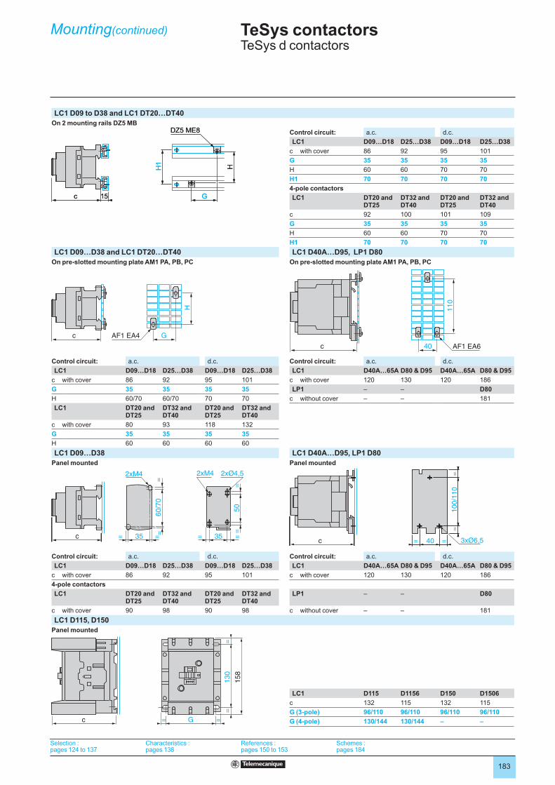
183
TeSys contactors 5 TeSys d contactors
Mounting(continued) 5
LC1 D09 to D38 and LC1 DT20…DT40
On 2 mounting rails DZ5 MB
Control circuit: a.c. d.c.
LC1 D09…D18 D25…D38 D09…D18 D25…D38
c with cover 86 92 95 101
G 35 35 35 35
H 60 60 70 70
H1 70 70 70 70
4-pole contactors
LC1 DT20 and DT25
DT32 and DT40
DT20 and DT25
DT32 and DT40
c 92 100 101 109
G 35 35 35 35
H 60 60 70 70
H1 70 70 70 70
LC1 D09…D38 and LC1 DT20…DT40 LC1 D40A…D95, LP1 D80
On pre-slotted mounting plate AM1 PA, PB, PC On pre-slotted mounting plate AM1 PA, PB, PC
Control circuit: a.c. d.c. Control circuit: a.c. d.c.
LC1 D09…D18 D25…D38 D09…D18 D25…D38 LC1 D40A…65A D80 & D95 D40A…65A D80 & D95
c with cover 86 92 95 101 c with cover 120 130 120 186
G 35 35 35 35 LP1 – – D80
H 60/70 60/70 70 70 c without cover – – 181
LC1 DT20 and DT25
DT32 and DT40
DT20 and DT25
DT32 and DT40
c with cover 80 93 118 132
G 35 35 35 35
H 60 60 60 60
LC1 D09…D38 LC1 D40A…D95, LP1 D80
Panel mounted Panel mounted
Control circuit: a.c. d.c. Control circuit: a.c. d.c.
LC1 D09…D18 D25…D38 D09…D18 D25…D38 LC1 D40A…65A D80 & D95 D40A…65A D80 & D95
c with cover 86 92 95 101 c with cover 120 130 120 186
4-pole contactors
LC1 DT20 and DT25
DT32 and DT40
DT20 and DT25
DT32 and DT40
LP1 – – D80
c with cover 90 98 90 98 c without cover – – 181
LC1 D115, D150
Panel mounted
LC1 D115 D1156 D150 D1506
c 132 115 132 115
G (3-pole) 96/110 96/110 96/110 96/110
G (4-pole) 130/144 130/144 – –
c 15
HH1
DZ5 ME8
Gc 15
HH1
DZ5 ME8
G
H
AF1 EA4 Gc
H
AF1 EA4 Gc
AF1 EA640
110
c AF1 EA640
110
c
c 40= =
10
0/1
10
==
3xØ6,5c 40= =
10
0/1
10
==
3xØ6,5
50
2xM4
==
60/7
0=
=
35= =35= =
2xØ4,52xM4
c
50
2xM4
==
60/7
0=
=
35= =35= =
2xØ4,52xM4
c
13
0=
=
15
8
c G= =
13
0=
=
15
8
c G= =
Selection :pages 124 to 137
Characteristics : pages 138
References : pages 150 to 153
Schemes : pages 184
Selection :pages 124 to 137
Characteristics : pages 138
References : pages 150 to 153
Schemes : pages 184
Selection :pages 124 to 137
Characteristics : pages 138
References : pages 150 to 153
Schemes : pages 184
Selection :pages 124 to 137
Characteristics : pages 138
References : pages 150 to 153
Schemes : pages 184

184
TeSys contactors 5 TeSys d contactors
Schemes
Contactors3-pole contactors (References: pages 150 to 153)
LC1 D09 to D150
4-pole contactors (References: pages 152 and 153)
LC1 DT20 to DT80A LC1 D115004 LC1 D098 to D258 LC1 and LP1 D40008 to D80008
Front mounting add-on contact blocksInstantaneous auxiliary contacts (References: page 167)
1 N/O LAD N10 (1) 1 N/C LAD N01 (1) 1 N/O + 1 N/C LAD N11 2 N/O LAD N20
2 N/C LAD N02 2 N/O + 2 N/C LAD N22 1 N/O + 3 N/C LAD N13 4 N/O LAD N40
4 N/C LAD N04 2 N/O + 2 N/C including 1 N/O + 1 N/C make before break LAD C22 3 N/O + 1 N/C LAD N31
Instantaneous auxiliary contacts conforming to standard EN 50012 (References: page 167)
1 N/O + 1 N/C LAD N11G 1 N/O + 1 N/C LAD N11P 2 N/O + 2 N/C LAD N22G 2 N/O + 2 N/C LAD N22P
3 N/O + 1 N/C LAD N31G 3 N/O + 1 N/C LADN31P 1 N/O + 3 N/C LAD N13G 1 N/O + 3 N/C LAD N13P
(1) Items in brackets refer to blocks mounted on right-hand side of contactor.
A1
A2
13/N
O14
1/L
12/T
1
3/L
2
5/L
3
22
21/N
C
4/T
2
6/T
3
A1
A2
13/N
O14
1/L
12/T
1
3/L
2
5/L
3
22
21/N
C
4/T
2
6/T
3
A1
A2
1/L1
2/T1
3/L2
4/T2
5/L3
6/T3
7/L4
8/T4
A1
A2
1/L1
2/T1
3/L2
4/T2
5/L3
6/T3
7/L4
8/T4
A1
A2
12
R1
R2
R3
R4
34
13/N
O14
22
21/N
C
A1
A2
12
R1
R2
R3
R4
34
13/N
O14
22
21/N
C
A1
A2
R1
R2
R3
R4
12
34
A1
A2
R1
R2
R3
R4
12
34
43 N
O44
43/N
O
(94)
(93)
43 N
O44
43/N
O
(94)
(93)
42
41
/NC
(91
)(9
2)
42
41
/NC
(91
)(9
2)
53
/NO
54 62
61
/NC
53
/NO
54 62
61
/NC
63
/NO
64
53
/NO
54
63
/NO
64
53
/NO
54
52
51/N
C
62
61/N
C
52
51/N
C
62
61/N
C
72
71
/NC
62
61
/NC
83
/NO
84
53
/NO
54
72
71
/NC
62
61
/NC
83
/NO
84
53
/NO
54
72
71
/NC
62
61
/NC
53
/NO
54
82
81
/NC
72
71
/NC
62
61
/NC
53
/NO
54
82
81
/NC
83/N
O84
73/N
O74
63/N
O64
53/N
O54
83/N
O84
73/N
O74
63/N
O64
53/N
O54
52
51/N
C
62
61/N
C
72
71/N
C
82
81/N
C
52
51/N
C
62
61/N
C
72
71/N
C
82
81/N
C
53
/NO
54
61
/NC
62
87
/NO
88
75
/NC
76
53
/NO
54
61
/NC
62
87
/NO
88
75
/NC
76
62
61
/NC
83
/NO
84
73
/NO
74
53
/NO
54
62
61
/NC
83
/NO
84
73
/NO
74
53
/NO
54
32
31/N
C
43/N
O44
32
31/N
C
43/N
O44
22
21
/NC
13
/NO
14
22
21
/NC
13
/NO
14
32
31/N
C
42
41/N
C
63/N
O64
53/N
O54
32
31/N
C
42
41/N
C
63/N
O64
53/N
O54
32
31/N
C
22
21/N
C
43/N
O44
13/N
O14
32
31/N
C
22
21/N
C
43/N
O44
13/N
O14
32
31
/NC
43
/NO
44
63
/NO
64
53
/NO
54
32
31
/NC
43
/NO
44
63
/NO
64
53
/NO
54
22
21
/NC
33
/NO
34
13
/NO
14
43
/NO
44
22
21
/NC
33
/NO
34
13
/NO
14
43
/NO
44
42
41
/NC
32
31
/NC
52
51
/NC
63
/NO
64
42
41
/NC
32
31
/NC
52
51
/NC
63
/NO
64
32
31
/NC
22
21
/NC
13
/NO
14
42
41
/NC
32
31
/NC
22
21
/NC
13
/NO
14
42
41
/NC
Selection :pages 124 to 137
Caractéristiques :page 138
References :pages 150 to 171
Dimensions :page 180
Selection :pages 124 to 137
Caractéristiques :page 138
References :pages 150 to 171
Dimensions :page 180
Selection :pages 124 to 137
Caractéristiques :page 138
References :pages 150 to 171
Dimensions :page 180
Selection :pages 124 to 137
Caractéristiques :page 138
References :pages 150 to 171
Dimensions :page 180
Selection :pages 124 to 137
Caractéristiques :page 138
References :pages 150 to 171
Dimensions :page 180
Selection :pages 124 to 137
Caractéristiques :page 138
References :pages 150 to 171
Dimensions :page 180
Selection :pages 124 to 137
Caractéristiques :page 138
References :pages 150 to 171
Dimensions :page 180
Selection :pages 124 to 137
Caractéristiques :page 138
References :pages 150 to 171
Dimensions :page 180
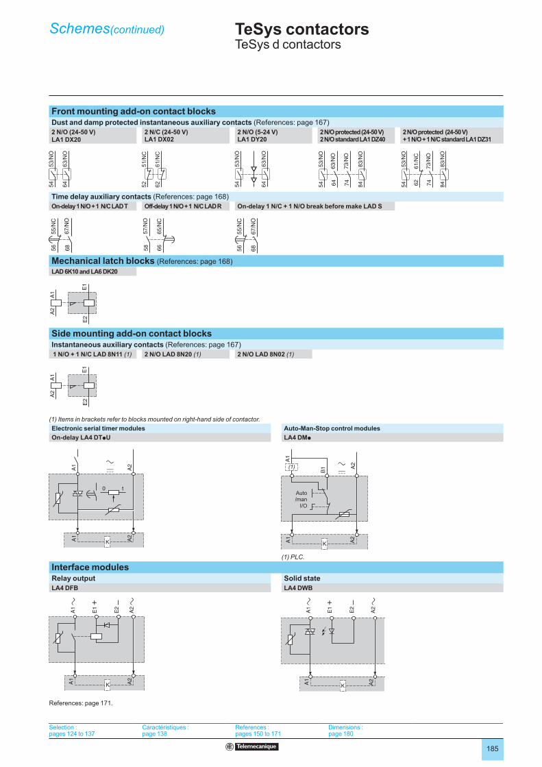
185
TeSys contactors 5 TeSys d contactors
Schemes(continued)
Selection :pages 124 to 137
Caractéristiques :page 138
References :pages 150 to 171
Dimensions :page 180
Selection :pages 124 to 137
Caractéristiques :page 138
References :pages 150 to 171
Dimensions :page 180
Front mounting add-on contact blocksDust and damp protected instantaneous auxiliary contacts (References: page 167)
2 N/O (24-50 V) LA1 DX20
2 N/C (24-50 V) LA1 DX02
2 N/O (5-24 V) LA1 DY20
2 N/O protected (24-50 V) 2 N/O standard LA1 DZ40
2 N/O protected (24-50 V) + 1 N/O + 1 N/C standard LA1 DZ31
Time delay auxiliary contacts (References: page 168)
On-delay 1 N/O + 1 N/C LAD T Off-delay 1 N/O + 1 N/C LAD R On-delay 1 N/C + 1 N/O break before make LAD S
Mechanical latch blocks (References: page 168)
LAD 6K10 and LA6 DK20
Side mounting add-on contact blocksInstantaneous auxiliary contacts (References: page 167)
1 N/O + 1 N/C LAD 8N11 (1) 2 N/O LAD 8N20 (1) 2 N/O LAD 8N02 (1)
(1) Items in brackets refer to blocks mounted on right-hand side of contactor.
Electronic serial timer modules Auto-Man-Stop control modules
On-delay LA4 DTpU LA4 DMp
(1) PLC.
Interface modulesRelay output Solid state
LA4 DFB LA4 DWB
References: page 171.
53/N
O54
83/N
O84
63/N
O64
73/N
O74
53/N
O54
83/N
O84
63/N
O64
73/N
O74
62
61/N
C
53/N
O54
83/N
O84
73/N
O74
62
61/N
C
53/N
O54
83/N
O84
73/N
O74
55/N
C56
67/N
O68
55/N
C56
67/N
O68
66
65
/NC
57
/NO
58
66
65
/NC
57
/NO
58
67/N
O68
55/N
C56
67/N
O68
55/N
C56
A1
A2
E1
E2
A1
A2
E1
E2
A1
A2
E1
E2
A1
A2
E1
E2
Auto
/manI/O
Auto
/manI/O
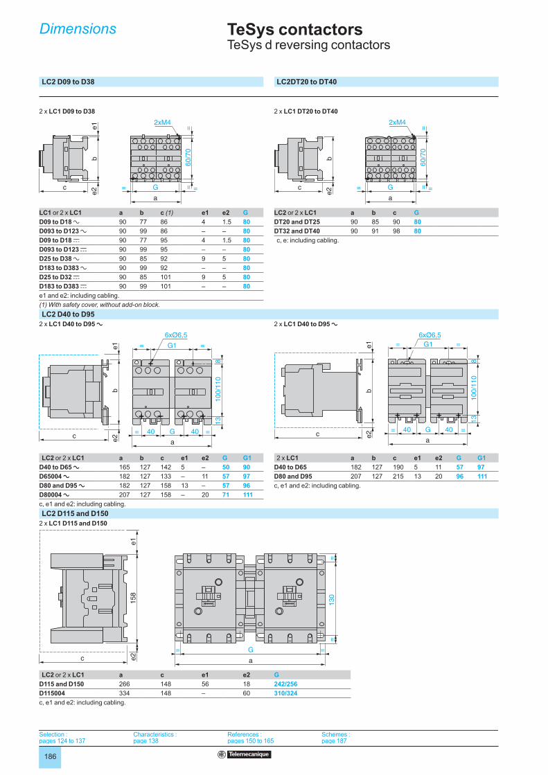
186
TeSys contactors TeSys d reversing contactors
LC2 D09 to D38 LC2DT20 to DT40
2 x LC1 D09 to D38 2 x LC1 DT20 to DT40
LC1 or 2 x LC1 a b c (1) e1 e2 G LC2 or 2 x LC1 a b c G
D09 to D18 a 90 77 86 4 1.5 80 DT20 and DT25 90 85 90 80
D093 to D123 a 90 99 86 – – 80 DT32 and DT40 90 91 98 80
D09 to D18 c 90 77 95 4 1.5 80 c, e: including cabling.
D093 to D123 c 90 99 95 – – 80
D25 to D38 a 90 85 92 9 5 80
D183 to D383 a 90 99 92 – – 80
D25 to D32 c 90 85 101 9 5 80
D183 to D383 c 90 99 101 – – 80
e1 and e2: including cabling.
(1) With safety cover, without add-on block.
LC2 D40 to D95
2 x LC1 D40 to D95 a 2 x LC1 D40 to D95 a
LC2 or 2 x LC1 a b c e1 e2 G G1 2 x LC1 a b c e1 e2 G G1
D40 to D65 a 165 127 142 5 – 50 90 D40 to D65 182 127 190 5 11 57 97
D65004 a 182 127 133 – 11 57 97 D80 and D95 207 127 215 13 20 96 111
D80 and D95 a 182 127 158 13 – 57 96 c, e1 and e2: including cabling.
D80004 a 207 127 158 – 20 71 111
c, e1 and e2: including cabling.
LC2 D115 and D150
2 x LC1 D115 and D150
LC2 or 2 x LC1 a c e1 e2 G
D115 and D150 266 148 56 18 242/256
D115004 334 148 – 60 310/324
c, e1 and e2: including cabling.
2xM4
G
a
= =60/7
0=
=c
be1
e2
2xM4
G
a
= =60/7
0=
=c
be1
e2
2xM4
G
a
= =
60
/70
==c
be
2
2xM4
G
a
= =
60
/70
==c
be
2
c
be
1e
2
G1= =
6xØ6,5
40
a
= =G 40
10
0/1
10
81
3
c
be
1e
2
G1= =
6xØ6,5
40
a
= =G 40
10
0/1
10
81
3
c
be1
e2
G1= =
6xØ6,5
40
a
= =G 40
100/1
10
813
c
be1
e2
G1= =
6xØ6,5
40
a
= =G 40
100/1
10
813
158
e1
e2
c
G
a
= =
130
==
158
e1
e2
c
G
a
= =
130
==
Selection :pages 124 to 137
Characteristics :page 138
References :pages 150 to 165
Schemes :page 187
Selection :pages 124 to 137
Characteristics :page 138
References :pages 150 to 165
Schemes :page 187
Selection :pages 124 to 137
Characteristics :page 138
References :pages 150 to 165
Schemes :page 187
Selection :pages 124 to 137
Characteristics :page 138
References :pages 150 to 165
Schemes :page 187
Dimensions
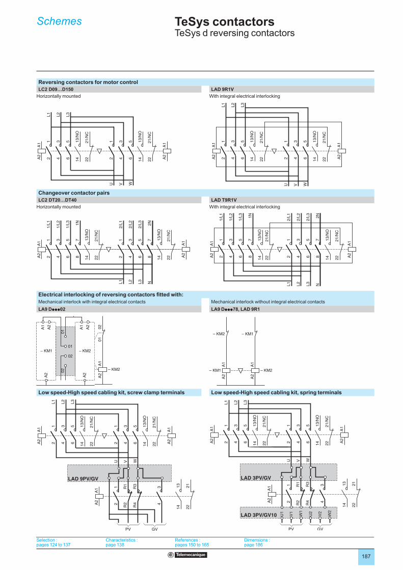
187
TeSys contactors TeSys d reversing contactors
Reversing contactors for motor control
LC2 D09…D150 LAD 9R1V
Horizontally mounted With integral electrical interlocking
Changeover contactor pairs
LC2 DT20…DT40 LAD T9R1V
Horizontally mounted With integral electrical interlocking
Electrical interlocking of reversing contactors fitted with:
Mechanical interlock with integral electrical contacts Mechanical interlock without integral electrical contacts
LA9 Dppp02 LA9 Dppp78, LAD 9R1
A1
A2
– KM1
01
02
A1
A2
– KM2
01
02
Low speed-High speed cabling kit, screw clamp terminals Low speed-High speed cabling kit, spring terminals
14
A1
A2
12
34
56
L1
L2
L3
12
34
56
U V W
13
/NO
14
13
/NO
A1
A2
22
21
/NC
22
21
/NC
14
A1
A2
12
34
56
L1
L2
L3
12
34
56
U V W
13
/NO
14
13
/NO
A1
A2
22
21
/NC
22
21
/NC
14
A1
A2
12
34
56
L1
L2
L3
12
34
56
U V W
13/N
O
14
13/N
O
A1
A2
22
21/N
C
22
21/N
C
14
A1
A2
12
34
56
L1
L2
L3
12
34
56
U V W
13/N
O
14
13/N
O
A1
A2
22
21/N
C
22
21/N
C
A1
A2
12
34
56
1/L
1
1/L
2
1/L
3
12
34
78
L1
L2
N
56
L3
78
1N
2/L
1
2/L
2
2/L
3
2N
14
13/N
O
22
21/N
C
14
13/N
O
A1
A2
22
21/N
C
A1
A2
12
34
56
1/L
1
1/L
2
1/L
3
12
34
78
L1
L2
N
56
L3
78
1N
2/L
1
2/L
2
2/L
3
2N
14
13/N
O
22
21/N
C
14
13/N
O
A1
A2
22
21/N
C
12
34
56
1/L
1
1/L
2
1/L
3
12
34
78
L1
L2
N
56
L3
78
1N
2/L
1
2/L
2
2/L
3
2N
14
A1
A2
13
/NO
14
13
/NO
A1
A2
22
21
/NC
22
21
/NC
12
34
56
1/L
1
1/L
2
1/L
3
12
34
78
L1
L2
N
56
L3
78
1N
2/L
1
2/L
2
2/L
3
2N
14
A1
A2
13
/NO
14
13
/NO
A1
A2
22
21
/NC
22
21
/NC
01
02
01
02
A1
A2
A2
A1
A2
A2
– KM2– KM1
01
02
01
02
A1
A2
A2
A1
A2
A2
– KM2– KM1
A1
A2
– KM1
– KM2
A1
A2
– KM2
– KM1
A1
A2
– KM1
– KM2
A1
A2
– KM2
– KM1
14
A1
A2
12
34
56
12
34
L1
L2
L3
12
34
56
U V W
13/N
O
14
13/N
O
A1
A2
A1
A2
22
21/N
C
22
21/N
C
14
13
22
21
PV GV
R1
R2
R3
R4
LAD 9PV/GV
14
A1
A2
12
34
56
12
34
L1
L2
L3
12
34
56
U V W
13/N
O
14
13/N
O
A1
A2
A1
A2
22
21/N
C
22
21/N
C
14
13
22
21
PV GV
R1
R2
R3
R4
LAD 9PV/GV
14
A1
A2
12
34
56
12
34
L1
L2
L3
12
34
56
U V W
13
/NO
14
13
/NO
A1
A2
A1
A2
22
21
/NC
22
21
/NC
PV GV
R1
R2
R3
R4
LAD 3PV/GV
U1
V1
W1
U2
V2
W2
LAD 3PV/GV10
14
13
22
21
14
A1
A2
12
34
56
12
34
L1
L2
L3
12
34
56
U V W
13
/NO
14
13
/NO
A1
A2
A1
A2
22
21
/NC
22
21
/NC
PV GV
R1
R2
R3
R4
LAD 3PV/GV
U1
V1
W1
U2
V2
W2
LAD 3PV/GV10
14
13
22
21
Selection :pages 124 to 137
Characteristics :page 138
References :pages 150 to 165
Dimensions :page 186
Selection :pages 124 to 137
Characteristics :page 138
References :pages 150 to 165
Dimensions :page 186
Selection :pages 124 to 137
Characteristics :page 138
References :pages 150 to 165
Dimensions :page 186
Selection :pages 124 to 137
Characteristics :page 138
References :pages 150 to 165
Dimensions :page 186
Schemes

188
189
Motor starters up to 150 A
TeSys d thermal overload relays
General: motor and machine protection . . . . . . . . . . . . . . . . . . . . . . . . . page 190
“Protection relays and controllers” selection guide. . . . . . . . . . . . . . . .page 196
TeSys d thermal overload relays
Presentation . . . . . . . . . . . . . . . . . . . . . . . . . . . . . . . . . . . . . . . . . . . . . page 198
Description . . . . . . . . . . . . . . . . . . . . . . . . . . . . . . . . . . . . . . . . . . . . . . page 198
Characteristics . . . . . . . . . . . . . . . . . . . . . . . . . . . . . . . . . . . . . . . . . . . page 199
Relays references . . . . . . . . . . . . . . . . . . . . . . . . . . . . . . . . . . . . . . . . page 204
Accessories references . . . . . . . . . . . . . . . . . . . . . . . . . . . . . . . . . . . . page 209
Dimensions . . . . . . . . . . . . . . . . . . . . . . . . . . . . . . . . . . . . . . . . . . . . . page 210
Schemes . . . . . . . . . . . . . . . . . . . . . . . . . . . . . . . . . . . . . . . . . . . . . . . page 213
b
v
v
v
v
v
v
v
Contents
190
Protection components 0 Motor and machine protection
General
IntroductionExceeding the operating limits of an electric motor will lead, eventually, not only to
destruction of the motor itself but also of the mechanisms it drives.
This type of load can be the cause of electrical or mechanical faults.
Electrical faults:
overvoltage, voltage drop, imbalance and phase failure which cause variations in
the current drawn,
short-circuits which can cause the current to reach levels capable of destroying
the load.
Mechanical faults:
locked rotor,
brief or prolonged overload which leads to an increase in the current drawn by the
motor, and therefore overheating.
The cost of these faults must take into account loss of production, loss of raw
materials, repair of the production tool, poor quality of production and delays in
delivery.
These faults can also have dramatic consequences on the safety of persons in direct
or indirect contact with the motor.
To prevent these faults, protection measures are necessary. They make it possible to
isolate the equipment to be protected from the mains supply by measuring
variations in electrical values (voltage, current, etc…).
Each motor starter must therefore have:
short-circuit protection, to detect and break, as quickly as possible, abnormal
currents generally greater than 10 times the rated current (In).
overload protection, to detect increases in current up to about 10 In and switch
off the starter before overheating of the motor and conductors damages the
insulation.
This protection is provided by specific devices such as fuses, circuit-breakers and
thermal overload relays, or by more integrated devices offering several types of
protection.
bv
v
bvv
b
b

191
Protection components 0 Motor and machine protection
General (continued)
Causes, effects and consequences of various faults There are two types of fault:
Internal faults within the motor.
External faults: these are located outside the electric motor but their
consequences can lead to damage inside the motor.
bb
Faults Causes Effects Consequences on the motor and on the machine
Short-circuit Contact between several phases, or
between one phase and neutral or
between several turns of the same
phase.
Current peak
Electrodynamic forces on the
conductors
bb
Destruction of windings
Overvoltage Lightning
Electrostatic discharge
Operation
bbb
Dielectric breakdown in the windings Destruction of the windings due to loss of
insulation
Phase imbalance and phase failure
Opening of a phase
Single-phase load upstream of the
motor
Short-circuit between the turns of
the same winding
bb
b
Reduction of usable torque, efficiency
and speed
Increase in losses
Starting impossible if phase failure
b
bb
Overheating (1)
High starting frequency
Failure of the automation system
Too many manual control
operations
Numerous fault trips
bb
b
High stator and rotor temperature rise
due to the frequent start current
Overheating (1)
Consequences on the process
Voltage variations
Instability of the mains voltage
Connection of heavy loads
bb
Reduction of usable torque
Increase in losses
bb
Overheating (1)
Harmonics Pollution of the mains supply by
variable speed drives, inverters, etc...
Reduction of usable torque
Increase in losses
bb
Overheating (1)
Long starting time
Resistive torque too high (load too
heavy)
Voltage drop
b
b
Increase in starting time Overheating 1)
Jamming Mechanical problem (crusher)
Seizures
bb
Overcurrent Overheating (1)
Consequences on the process
No-load running Pump running empty
Mechanical break in drive to the
load
bb
Drop in current drawn Consequences on the process
Frequency fluctuations
Overload of a supply powered by
limited independent sources
Faulty alternator speed regulator
b
b
Increase in losses
Interferes with synchronous devices
(clock, recorder, ...)
bb
–
Overload Increase in resistive torque
Voltage drop
Drop in power factor
bbb
Increase in current consumption Overheating (1)
Loss of machine excitation
Significant drop in excitation
current
Break in rotor winding
b
b
Increase in active power
Drop in power factor
bb
Significant overheating of rotor and cage
Phase-Earth fault Accidental Phase-Earth contacts
Accidental Phase-machine casing
contacts (casing connected to earth)
bb
Overvoltage developed in the mains
supply
Rise in earth potential (safety of
persons)
b
b
Consequences on safety of persons
(1) Then, in the longer or shorter term, depending on the seriousness of the fault and/or its frequency, short-circuit and destruction of the windings.

192
Protection components 0 Motor and machine protection
General (continued)
Protection functions Short-circuit protection
General
A short-circuit results in a very rapid rise in current which can reach several hundred
times the value of the operational current. The consequences of a short-circuit are
dangerous to both equipment and persons. It is therefore imperative to use
protection devices to detect the fault and very quickly break the circuit.
Two types of protection are commonly used:
fuses (cutout) which break the circuit by melting, which then requires their
replacement,
magnetic trip circuit-breakers, often more simply called "magnetic circuit-
breakers", which only require re-setting to put them back into service.
Short-circuit protection can also be built-into multifunction devices such as motor
circuit-breakers and contactor-breakers.
The main characteristics of short-circuit protection devices are:
their breaking capacity: this is the highest prospective short-circuit current value
that a protection device can break at a given voltage.
their making capacity: this is the highest current value that the protection device
can make at its rated voltage in specified conditions.
The making capacity is equal to k times the breaking capacity.
b
b
b
b
Fuses (cutouts)
Fuses provide individual phase protection (single-pole), with a high breaking
capacity in a compact size:
mounted either in fuse carriers,
or in isolators, replacing the original links or shunt bars.
For motor protection, aM type fuses are used. Their design characteristics allow
them to conduct the high magnetising currents that occur when motors are switched
on. They are therefore unsuitable for overload protection (unlike gG type fuses). This
is why an overload relay must be included in the motor power supply circuit.
bb
Magnetic circuit-breakers
These circuit-breakers protect installations against short-circuits, within the limit of
their breaking capacity.
Magnetic circuit-breakers provide omnipole breaking as standard.
For relatively low short-circuit currents, the operation of a circuit-breaker is faster than
that of fuses.
This protection conforms to standard IEC 60947-2.
The thermal and electrodymanic effects are also limited, therefore ensuring better
protection of cables and equipment.
566997
566998
LS1 D32 fuse carrier
GS1 K4 switch disconnectors
566997
566998
LS1 D32 fuse carrier
GS1 K4 switch disconnectors
566999
GV2 Lmagnetic circuit-breraker
566999
GV2 Lmagnetic circuit-breraker
TeSys U LUB 12 starter with LUCApp control unit
510586
TeSys U LUB 12 starter with LUCApp control unit
510586

193
Protection components 0 Motor and machine protection
Protection functions (continued)
Overload protection
General
An overload condition is the most frequently encountered fault. The symptoms are a
rise in the current drawn by the motor and thermal effects. A rapid return to normal
operating conditions is important.
The actual operating conditions (ambient temperature, operating altitude and type of
standard duty) are essential to determine the operating values of the motor (power,
current) and to be able to select effective overload protection. These operational
values are given by the motor manufacturer.
According to the level required, protection can be provided by:
overload relays and thermal overload relays (bi-metallic or electronic type) which
protect motors in the event of:
overload, by monitoring the current drawn by each phase,
phase imbalance or failure, by their differential mechanism.
relays with PTC thermistor probes (Positive Temperature Coefficient).
overtorque relays,
multifunction relays.
b
vvbbb
Overload relays
These relays protect motors against overload. They must allow the temporary
overload that occurs on starting and must only trip if the starting time is abnormally
long.
The overload relay will be selected according to the length of the starting time
(tripping class) and the motor rating.
These relays have a thermal memory (except for certain electronic overload relays,
indicated by their manufacturers) and can be connected:
either in series with the load,
or to current transformers placed in series with the load.
Bi-metallic thermal overload relays
Combined with a contactor, these relays protect the line and the equipment against
small and prolonged overloads. They must be protected against strong overcurrent
by a circuit-breaker or fuses.
These relays may be used on an a.c. or d.c. system and are generally:
3-pole,
compensated, i.e. insensitive to ambient temperature variations,
with manual or automatic reset,
graduated with a "motor FLC" scale: allowing direct setting to the full load current
as shown on the motor rating plate.
They can also be sensitive to phase failure: this is known as 'differential'. This
function conforms to standards IEC 60947-4-1 and 60947-6-2
This type of relay is extremely reliable and is a relatively low cost device.
Electronic thermal overload relays
Electronic thermal overload relays have the advantage of electronics which allow a
more complex thermal image of the motor to be created.
They can be combined with products having complementary functions, such as:
temperature sensing via PTC probes,
protection against jamming and overtorque,
protection against phase reversal,
earth fault protection,
protection against no-load running,
alarm function.
bb
bbbb
bbbbbb
General (continued)
567000
LRD 02thermal overload relay
567002
RM4 JA current measurement relay
TeSys U starter with “thermal overload alarm” function module
LRD 365
536762
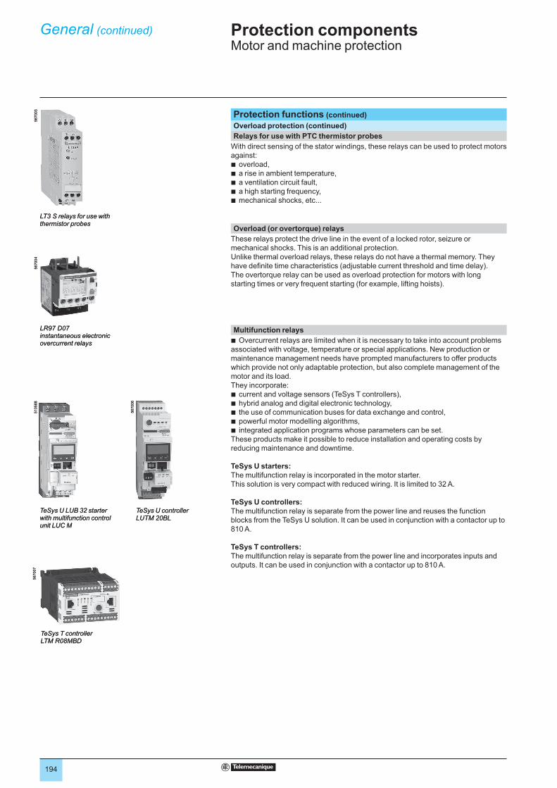
194
Protection components 0 Motor and machine protection
General (continued)
Protection functions (continued)
Overload protection (continued)
Relays for use with PTC thermistor probes
With direct sensing of the stator windings, these relays can be used to protect motors
against:
overload,
a rise in ambient temperature,
a ventilation circuit fault,
a high starting frequency,
mechanical shocks, etc...
bbbbb
Overload (or overtorque) relays
These relays protect the drive line in the event of a locked rotor, seizure or
mechanical shocks. This is an additional protection.
Unlike thermal overload relays, these relays do not have a thermal memory. They
have definite time characteristics (adjustable current threshold and time delay).
The overtorque relay can be used as overload protection for motors with long
starting times or very frequent starting (for example, lifting hoists).
Multifunction relays
Overcurrent relays are limited when it is necessary to take into account problems
associated with voltage, temperature or special applications. New production or
maintenance management needs have prompted manufacturers to offer products
which provide not only adaptable protection, but also complete management of the
motor and its load.
They incorporate:
current and voltage sensors (TeSys T controllers),
hybrid analog and digital electronic technology,
the use of communication buses for data exchange and control,
powerful motor modelling algorithms,
integrated application programs whose parameters can be set.
These products make it possible to reduce installation and operating costs by
reducing maintenance and downtime.
TeSys U starters:The multifunction relay is incorporated in the motor starter.
This solution is very compact with reduced wiring. It is limited to 32 A.
TeSys U controllers: The multifunction relay is separate from the power line and reuses the function
blocks from the TeSys U solution. It can be used in conjunction with a contactor up to
810 A.
TeSys T controllers: The multifunction relay is separate from the power line and incorporates inputs and
outputs. It can be used in conjunction with a contactor up to 810 A.
b
bbbbb
567003
LT3 S relays for use with thermistor probes
567003
LT3 S relays for use with thermistor probes
567004
LR97 D07instantaneous electronic overcurrent relays
567004
LR97 D07instantaneous electronic overcurrent relays
510588
TeSys U LUB 32 starter with multifunction control unit LUC M
510588
TeSys U LUB 32 starter with multifunction control unit LUC M
567006
TeSys U controller LUTM 20BL
567006
TeSys U controller LUTM 20BL
567007
TeSys T controller LTM R08MBD
567007
TeSys T controller LTM R08MBD
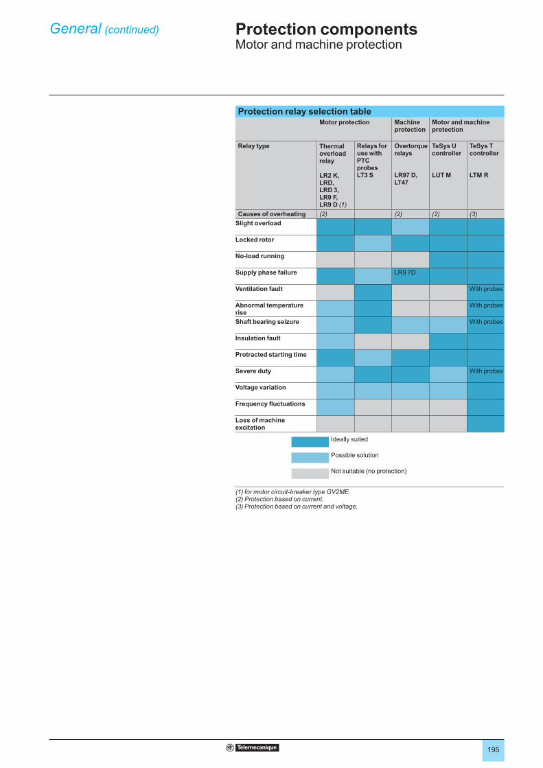
195
Protection components 0 Motor and machine protection
General (continued)
Protection relay selection table Motor protection Machine
protectionMotor and machine protection
Relay type Thermal overload relay
LR2 K, LRD,LRD 3, LR9 F, LR9 D (1)
Relays for use with PTC probes LT3 S
Overtorque relays
LR97 D, LT47
TeSys U controller
LUT M
TeSys T controller
LTM R
Causes of overheating (2) (2) (2) (3)
Slight overload
Locked rotor
No-load running
Supply phase failure LR9 7D
Ventilation fault With probes
Abnormal temperature rise
With probes
Shaft bearing seizure With probes
Insulation fault
Protracted starting time
Severe duty With probes
Voltage variation
Frequency fluctuations
Loss of machine excitation
Ideally suited
Possible solution
Not suitable (no protection)
(1) for motor circuit-breaker type GV2ME.(2) Protection based on current.(3) Protection based on current and voltage.
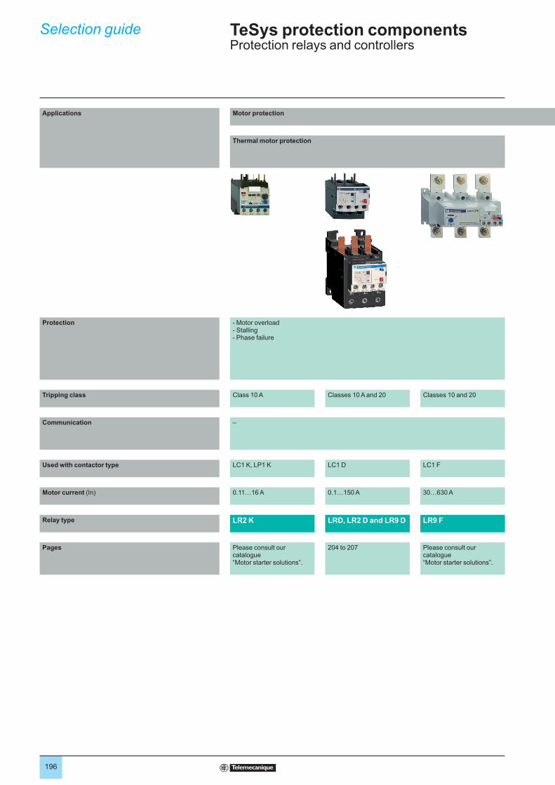
196
Applications Motor protection
Thermal motor protection
Protection - Motor overload- Stalling- Phase failure
Tripping class Class 10 A Classes 10 A and 20 Classes 10 and 20
Communication –
Used with contactor type LC1 K, LP1 K LC1 D LC1 F
Motor current (In) 0.11…16 A 0.1…150 A 30…630 A
Relay type LR2 K LRD, LR2 D and LR9 D LR9 F
Pages Please consult our catalogue “Motor starter solutions”.
204 to 207 Please consult our catalogue “Motor starter solutions”.
Selection guide TeSys protection componentsProtection relays and controllers