Embed Size (px)
Citation preview
8/4/2019 Digital Transmission 4
http://slidepdf.com/reader/full/digital-transmission-4 1/65
Kashif Bashir
Chapter 4
DIGITAL
TRANSMISSION
8/4/2019 Digital Transmission 4
http://slidepdf.com/reader/full/digital-transmission-4 2/65
Kashif Bashir 4.2
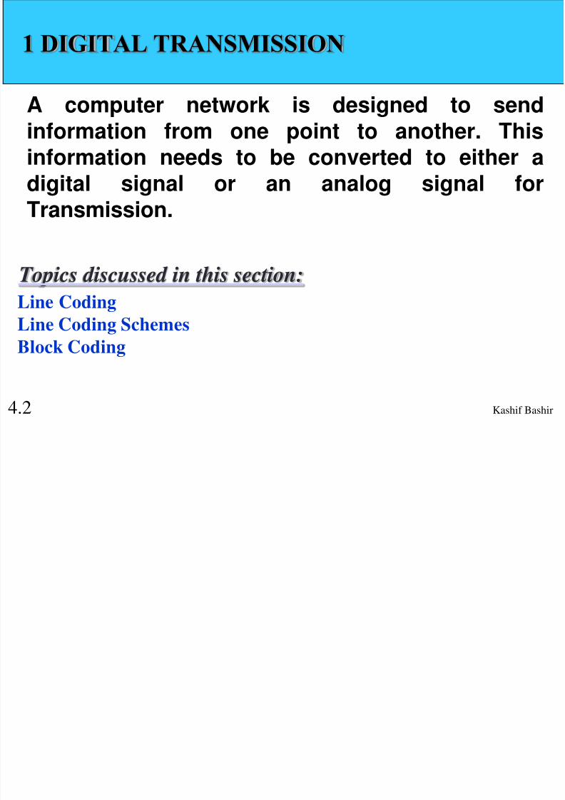
1 DIGITAL TRANSMISSION
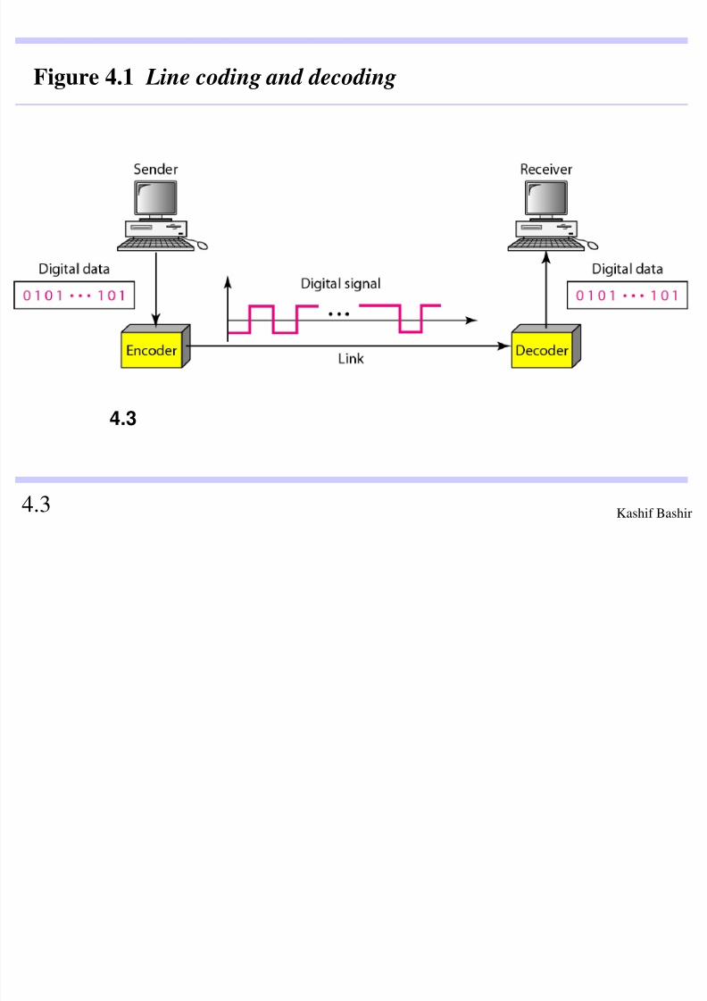
A computer network is designed to sendinformation from one point to another. Thisinformation needs to be converted to either adigital signal or an analog signal forTransmission.
Line Coding
Line Coding Schemes
Block Coding
Topics discussed in this section:
8/4/2019 Digital Transmission 4
http://slidepdf.com/reader/full/digital-transmission-4 3/65
Kashif Bashir 4.3
Figure 4.1 Line coding and decoding
4.3

8/4/2019 Digital Transmission 4
http://slidepdf.com/reader/full/digital-transmission-4 4/65
Kashif Bashir
The data rate defines the number of dataelements (bits) sent in 1 s. The unit isbits per second (bps). The data rate issometimes called the bit rate;
Note
4.4

8/4/2019 Digital Transmission 4
http://slidepdf.com/reader/full/digital-transmission-4 5/65
Kashif Bashir 4.5
The signal rate is the number of signalelements sent in Is. The unit is the baud.The signal rate is sometimes called thepulse rate, the modulation rate, or thebaud rate.
Note
8/4/2019 Digital Transmission 4
http://slidepdf.com/reader/full/digital-transmission-4 6/65
Kashif Bashir 4.6
One goal in data communications is toincrease the data rate while decreasingthe signal rate. Increasing the data rateincreases the speed of transmission;decreasing the signal rate decreases thebandwidth requirement.
Note
8/4/2019 Digital Transmission 4
http://slidepdf.com/reader/full/digital-transmission-4 7/65Kashif Bashir 4.7
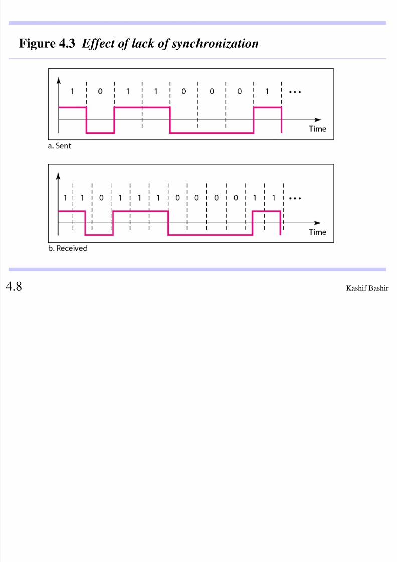
Self-synchronization To correctly interpret the signalsreceived from the sender, the receiver's bit intervals mustcorrespond exactly to the sender's bit intervals. If thereceiver clock is faster or slower, the bit intervals are notmatched and the receiver might misinterpret the signals.
Note
8/4/2019 Digital Transmission 4
http://slidepdf.com/reader/full/digital-transmission-4 8/65Kashif Bashir 4.8
Figure 4.3 Effect of lack of synchronization

8/4/2019 Digital Transmission 4
http://slidepdf.com/reader/full/digital-transmission-4 9/65Kashif Bashir 4.9
In a digital transmission, the receiver clock is 0.1 percent
faster than the sender clock. How many extra bits per second does the receiver receive if the data rate is
1 kbps? How many if the data rate is 1 Mbps?
Solution
At 1 kbps, the receiver receives 1001 bps instead of 1000
bps.
Example 4.2
At 1 Mbps, the receiver receives 1,001,000 bps instead of
1,000,000 bps.
8/4/2019 Digital Transmission 4
http://slidepdf.com/reader/full/digital-transmission-4 10/65Kashif Bashir
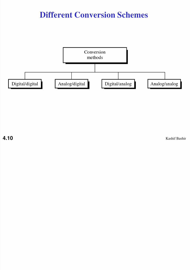
Different Conversion Schemes
4.10
8/4/2019 Digital Transmission 4
http://slidepdf.com/reader/full/digital-transmission-4 11/65Kashif Bashir
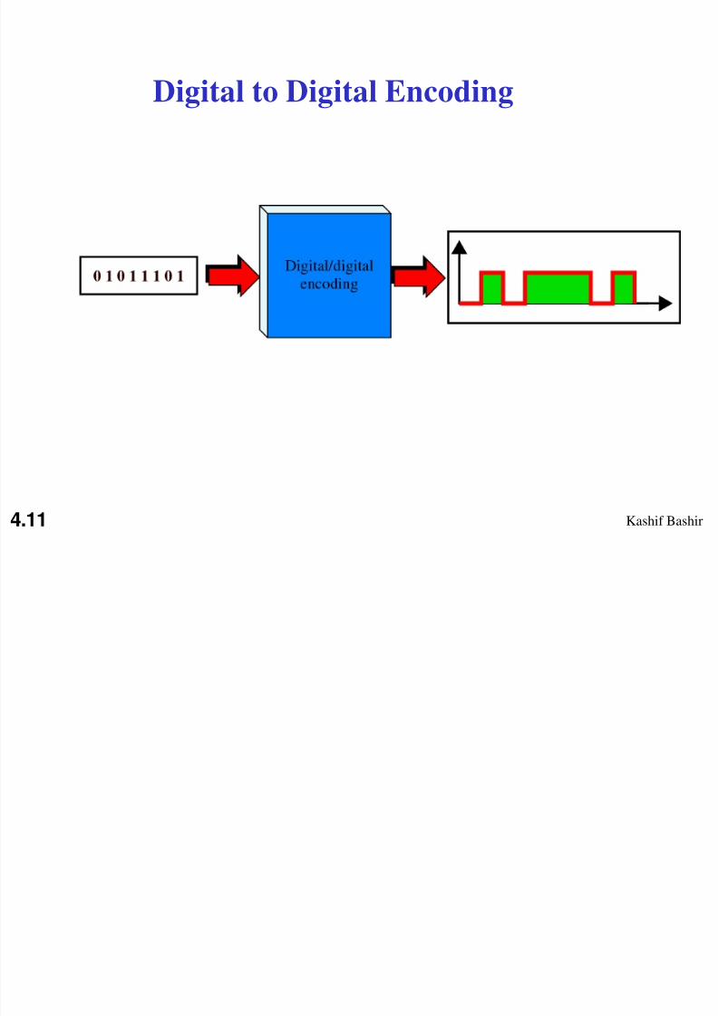
Digital to Digital Encoding
4.11
8/4/2019 Digital Transmission 4
http://slidepdf.com/reader/full/digital-transmission-4 12/65Kashif Bashir
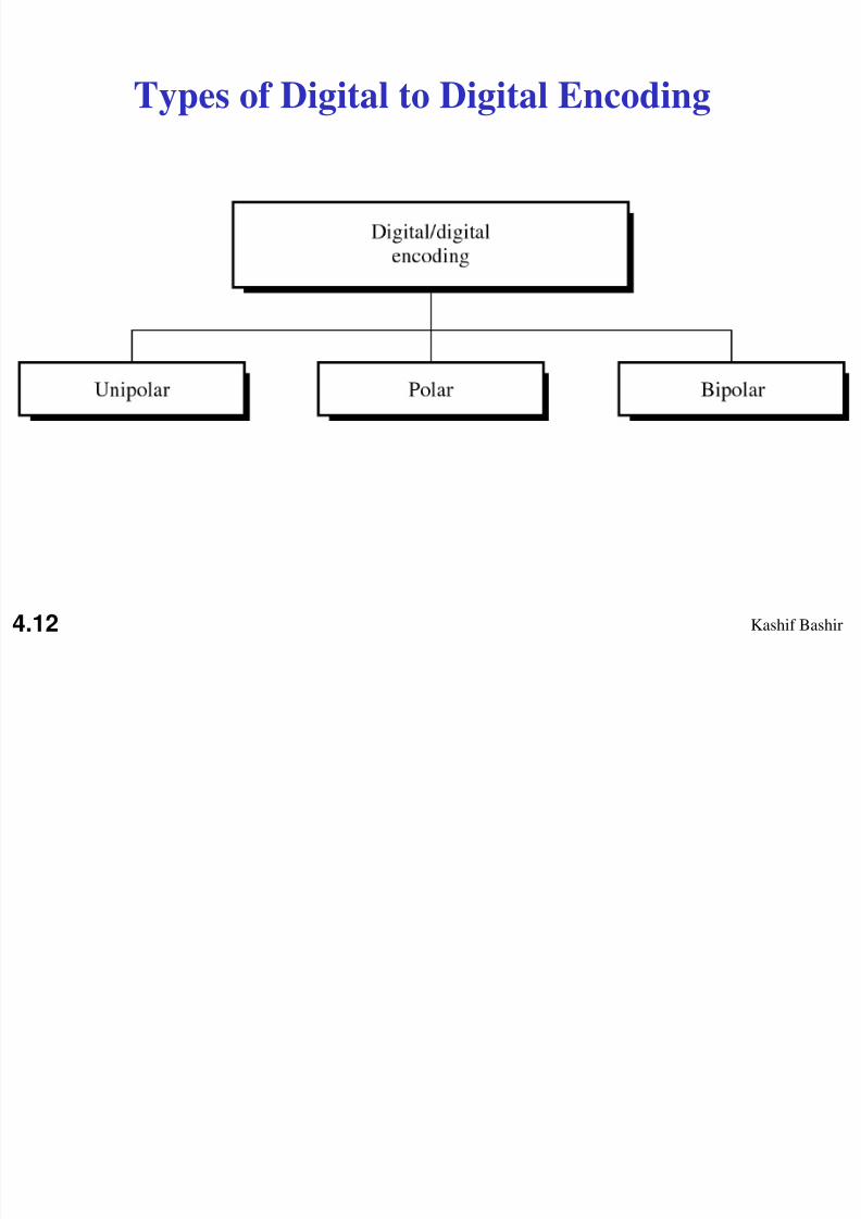
Types of Digital to Digital Encoding
4.12
8/4/2019 Digital Transmission 4
http://slidepdf.com/reader/full/digital-transmission-4 13/65Kashif Bashir
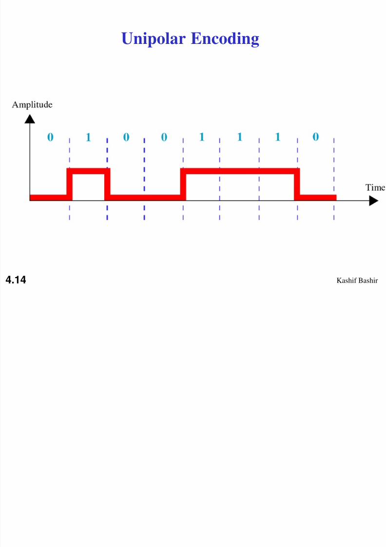
Unipolar encoding uses only one
voltage level.
Note:
4.13
8/4/2019 Digital Transmission 4
http://slidepdf.com/reader/full/digital-transmission-4 14/65Kashif Bashir
Unipolar Encoding
4.14

8/4/2019 Digital Transmission 4
http://slidepdf.com/reader/full/digital-transmission-4 15/65Kashif Bashir
Polar encoding uses two voltage levels
(positive and negative).
Note:
4.15

8/4/2019 Digital Transmission 4
http://slidepdf.com/reader/full/digital-transmission-4 16/65Kashif Bashir
Types of Polar Encoding
4.16

8/4/2019 Digital Transmission 4
http://slidepdf.com/reader/full/digital-transmission-4 17/65Kashif Bashir
In NRZ-L the level of the signal is
dependent upon the state of the bit.
Note:
4.17

8/4/2019 Digital Transmission 4
http://slidepdf.com/reader/full/digital-transmission-4 18/65
Kashif Bashir
In NRZ-I the signal is inverted if a 1 is
encountered.
Note:
4.18

8/4/2019 Digital Transmission 4
http://slidepdf.com/reader/full/digital-transmission-4 19/65
Kashif Bashir
NRZ-L and NRZ-I Encoding
4.19
8/4/2019 Digital Transmission 4
http://slidepdf.com/reader/full/digital-transmission-4 20/65
Kashif Bashir
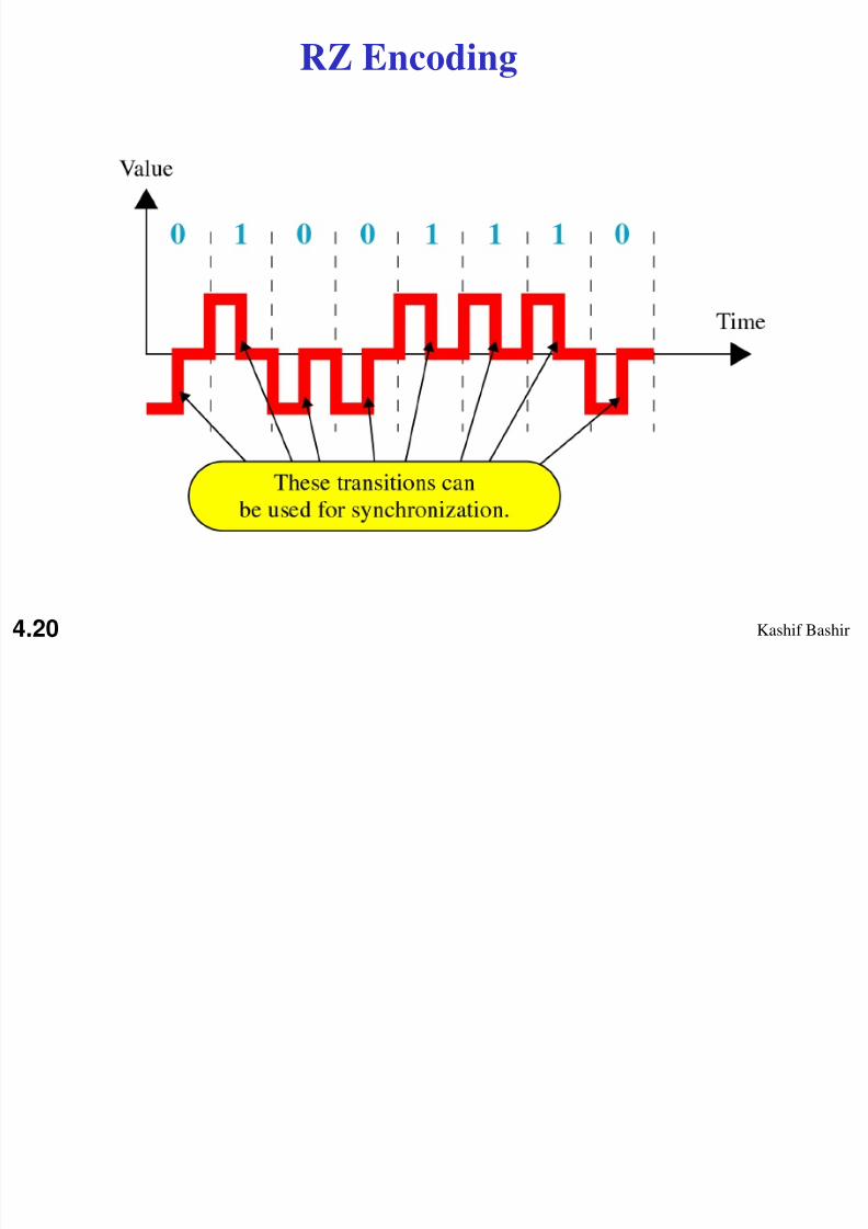
RZ Encoding
4.20
8/4/2019 Digital Transmission 4
http://slidepdf.com/reader/full/digital-transmission-4 21/65
Kashif Bashir
A good encoded digital signal must
contain a provision for synchronization.
Note:
4.21
8/4/2019 Digital Transmission 4
http://slidepdf.com/reader/full/digital-transmission-4 22/65
Kashif Bashir
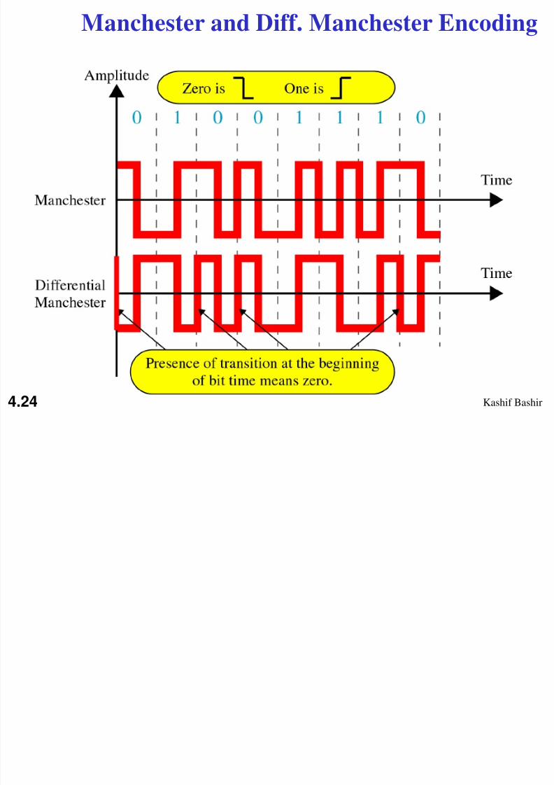
In Manchester encoding, the
transition at the middle of the bit isused for both synchronization and bit
representation.
Note:
4.22

8/4/2019 Digital Transmission 4
http://slidepdf.com/reader/full/digital-transmission-4 23/65
Kashif Bashir
In differential Manchester encoding,
the transition at the middle of the bit isused only for synchronization.
The bit representation is defined by the
inversion or noninversion at the beginning of the bit.
Note:
4.23
8/4/2019 Digital Transmission 4
http://slidepdf.com/reader/full/digital-transmission-4 24/65
Kashif Bashir
Manchester and Diff. Manchester Encoding
4.24
8/4/2019 Digital Transmission 4
http://slidepdf.com/reader/full/digital-transmission-4 25/65
Kashif Bashir
In Manchester Scheme the only
drawback is the signal rate. The signal rate for Manchester and differential
Manchester is double that for NRZ.
Note:
4.25
8/4/2019 Digital Transmission 4
http://slidepdf.com/reader/full/digital-transmission-4 26/65
Kashif Bashir
A long sequence of Os upsets the synchronization.
If we can find a way to avoid a long sequence of
Os in the original stream, we can use bipolar AMI for long distances.
Note:
4.26

8/4/2019 Digital Transmission 4
http://slidepdf.com/reader/full/digital-transmission-4 27/65
Kashif Bashir
In bipolar encoding, we use three
levels: positive, zero, and negative.
Note:
4.27
8/4/2019 Digital Transmission 4
http://slidepdf.com/reader/full/digital-transmission-4 28/65
Kashif Bashir
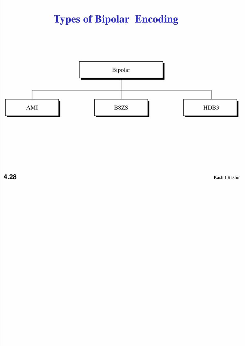
Types of Bipolar Encoding
4.28
8/4/2019 Digital Transmission 4
http://slidepdf.com/reader/full/digital-transmission-4 29/65
Kashif Bashir
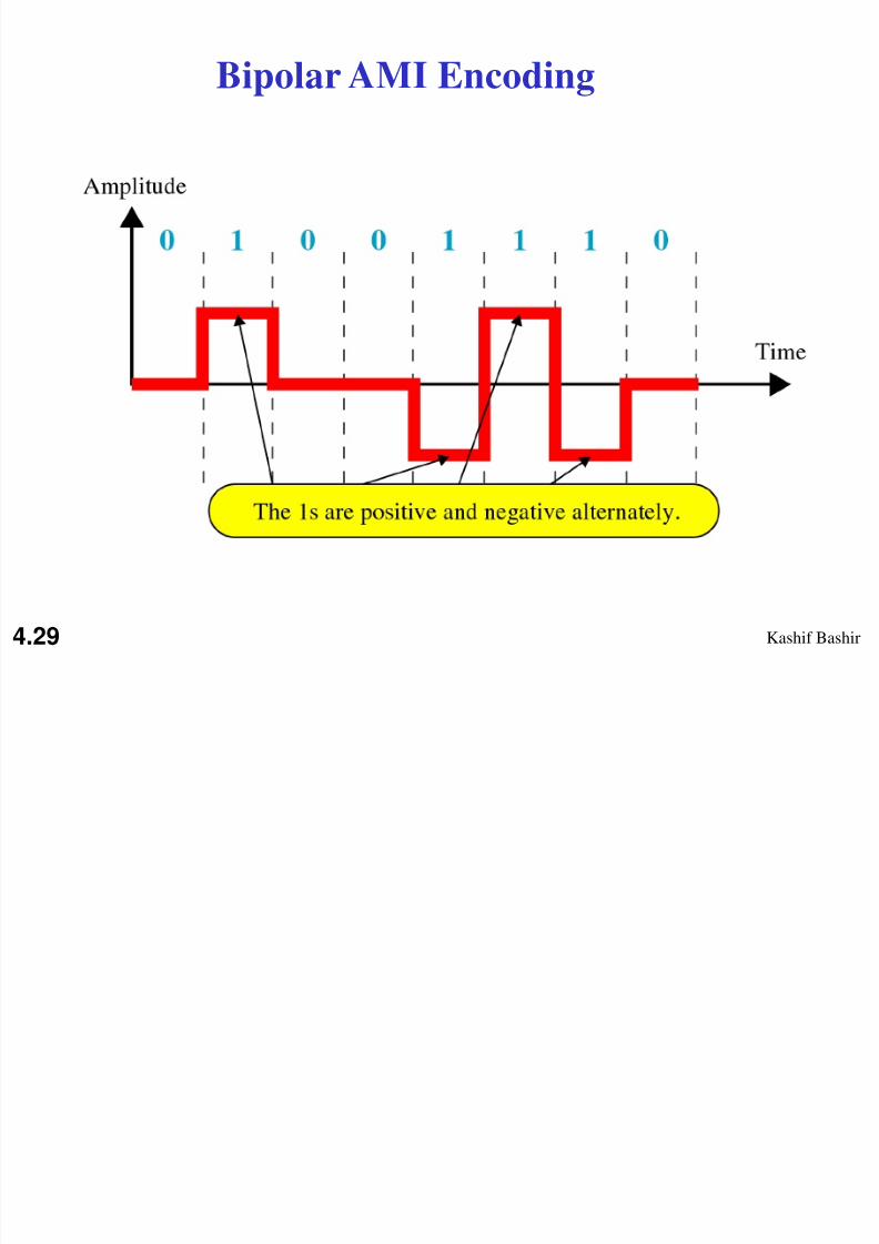
Bipolar AMI Encoding
4.29
8/4/2019 Digital Transmission 4
http://slidepdf.com/reader/full/digital-transmission-4 30/65
Kashif Bashir
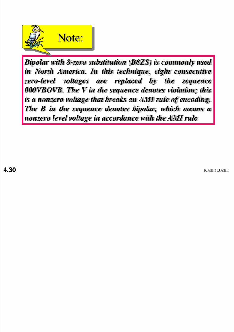
Bipolar with 8-zero substitution (B8ZS) is commonly used
in North America. In this technique, eight consecutive
zero-level voltages are replaced by the sequence000VBOVB. The V in the sequence denotes violation; this
is a nonzero voltage that breaks an AMI rule of encoding.
The B in the sequence denotes bipolar, which means a
nonzero level voltage in accordance with the AMI rule
Note:
4.30
8/4/2019 Digital Transmission 4
http://slidepdf.com/reader/full/digital-transmission-4 31/65
Kashif Bashir
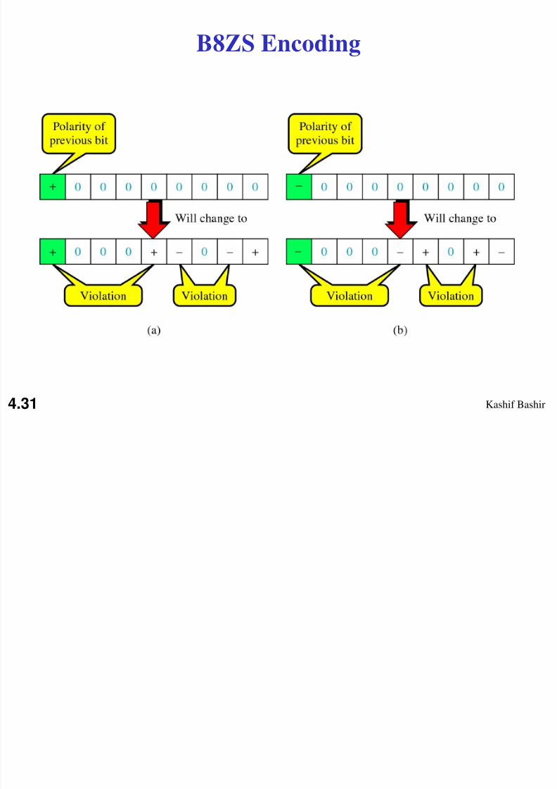
B8ZS Encoding
4.31

8/4/2019 Digital Transmission 4
http://slidepdf.com/reader/full/digital-transmission-4 32/65
Kashif Bashir 4.32
Figure 4.19 Two cases of B8ZS scrambling technique
8/4/2019 Digital Transmission 4
http://slidepdf.com/reader/full/digital-transmission-4 33/65
Kashif Bashir
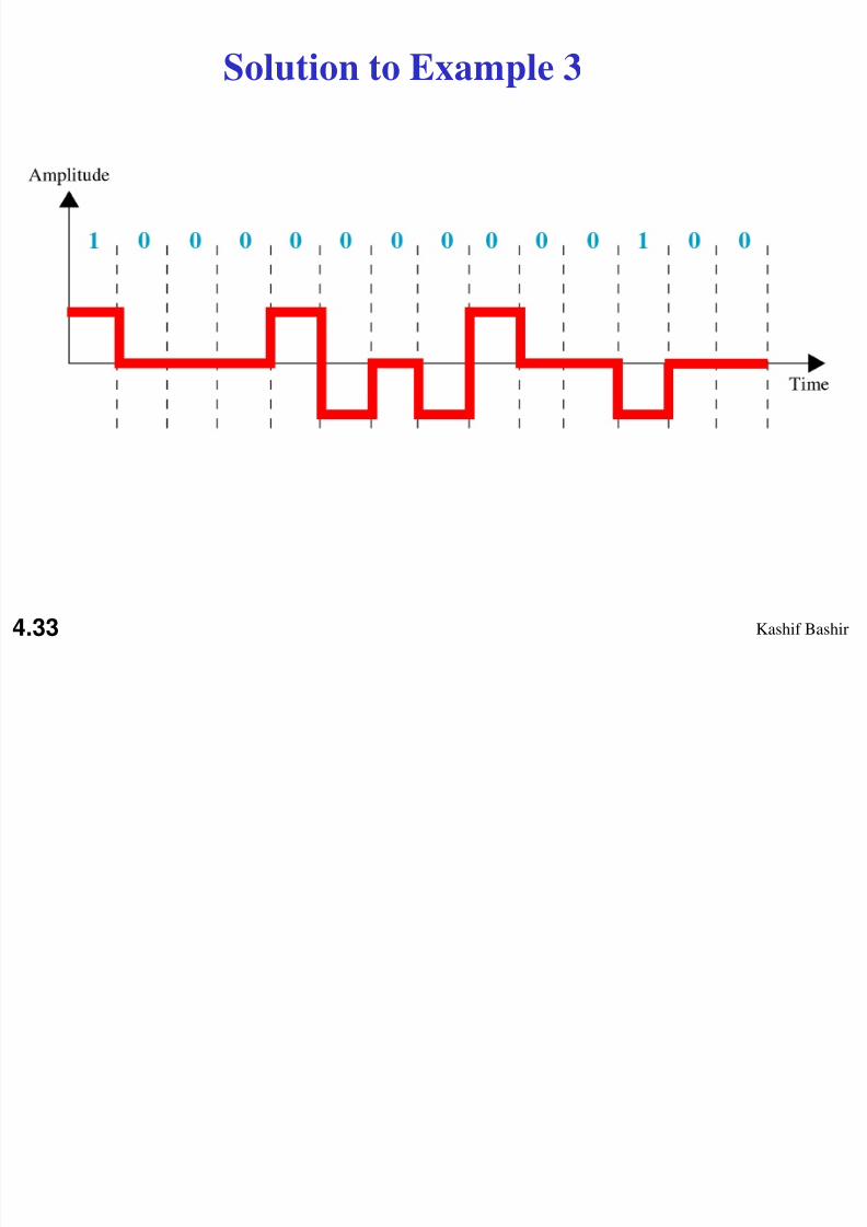
Solution to Example 3
4.33

8/4/2019 Digital Transmission 4
http://slidepdf.com/reader/full/digital-transmission-4 34/65
Kashif Bashir
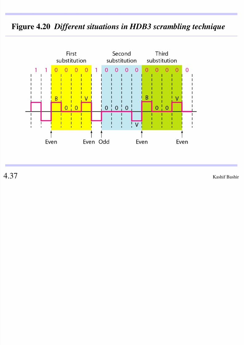
High density bipolar 3 zero (HDB3) is commonly used
outside of north America. In this technique, four
consecutive zero-level voltages are replaced with a sequenced with of 000V or B000V.
Note:
4.34
8/4/2019 Digital Transmission 4
http://slidepdf.com/reader/full/digital-transmission-4 35/65
Kashif Bashir
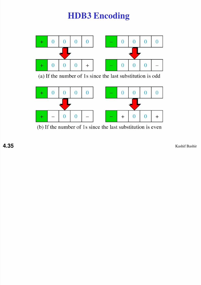
HDB3 Encoding
4.35

8/4/2019 Digital Transmission 4
http://slidepdf.com/reader/full/digital-transmission-4 36/65
Kashif Bashir
The two rules can be stated as follows:1. If the number of nonzero pulses after the last substitution is
odd, the substitution pattern will be 000V, which makes the
total number of nonzero pulses even.
2. If the number of nonzero pulses after the last substitution iseven, the substitution pattern will be B00V, which makes the
total number of nonzero pulses even.
High density bipolar 3 zero (HDB3)
8/4/2019 Digital Transmission 4
http://slidepdf.com/reader/full/digital-transmission-4 37/65
Kashif Bashir 4.37
Figure 4.20 Different situations in HDB3 scrambling technique
8/4/2019 Digital Transmission 4
http://slidepdf.com/reader/full/digital-transmission-4 38/65
Kashif Bashir
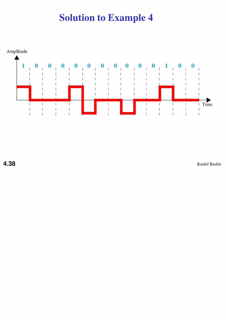
Solution to Example 4
4.38
8/4/2019 Digital Transmission 4
http://slidepdf.com/reader/full/digital-transmission-4 39/65
Kashif Bashir 4.39
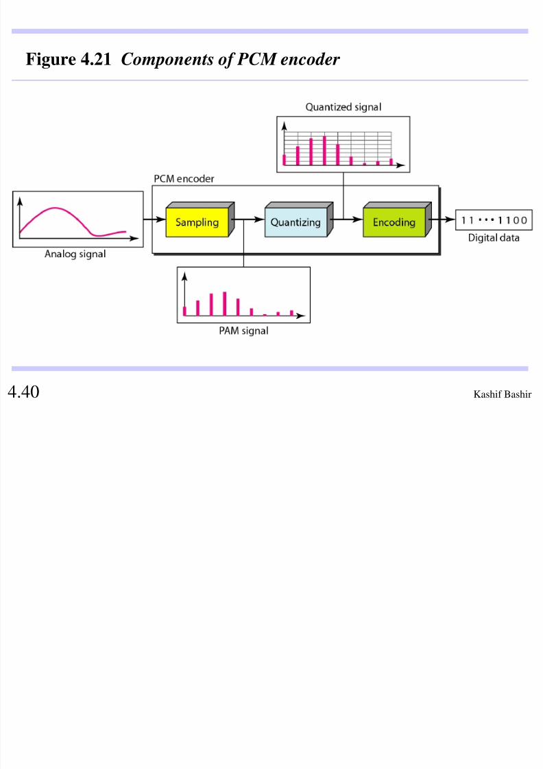
2 ANALOG-TO-DIGITAL CONVERSION
We have seen in Chapter 3 that a digital signal is
superior to an analog signal. The tendency today is to
change an analog signal to digital data. In this section
we describe two techniques, pulse code modulation
and delta modulation .
Pulse Code Modulation (PCM)
Delta Modulation (DM)
Topics discussed in this section:
8/4/2019 Digital Transmission 4
http://slidepdf.com/reader/full/digital-transmission-4 40/65
Kashif Bashir 4.40
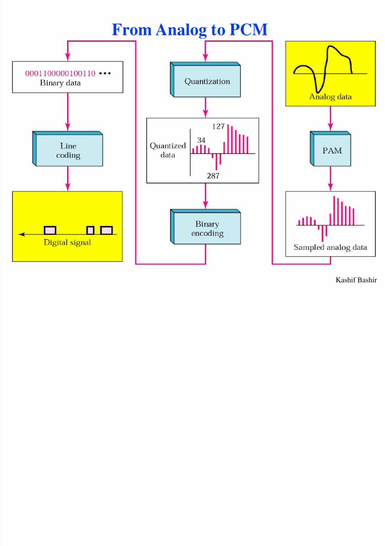
Figure 4.21 Components of PCM encoder
8/4/2019 Digital Transmission 4
http://slidepdf.com/reader/full/digital-transmission-4 41/65
Kashif Bashir
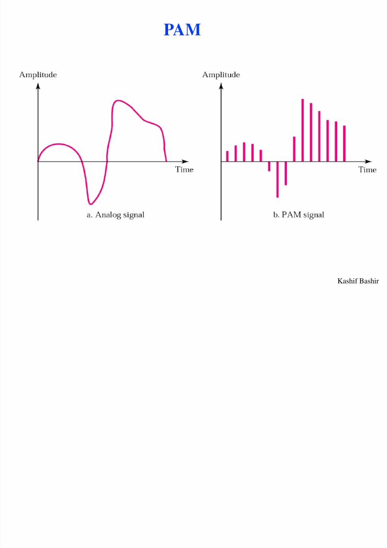
PAM

8/4/2019 Digital Transmission 4
http://slidepdf.com/reader/full/digital-transmission-4 42/65
Kashif Bashir
Quantized PAM Signal
8/4/2019 Digital Transmission 4
http://slidepdf.com/reader/full/digital-transmission-4 43/65
Kashif Bashir
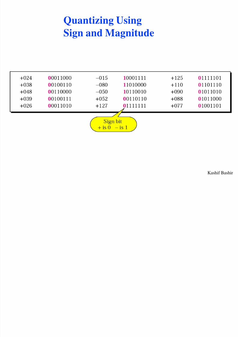
Quantizing Using
Sign and Magnitude
8/4/2019 Digital Transmission 4
http://slidepdf.com/reader/full/digital-transmission-4 44/65
Kashif Bashir
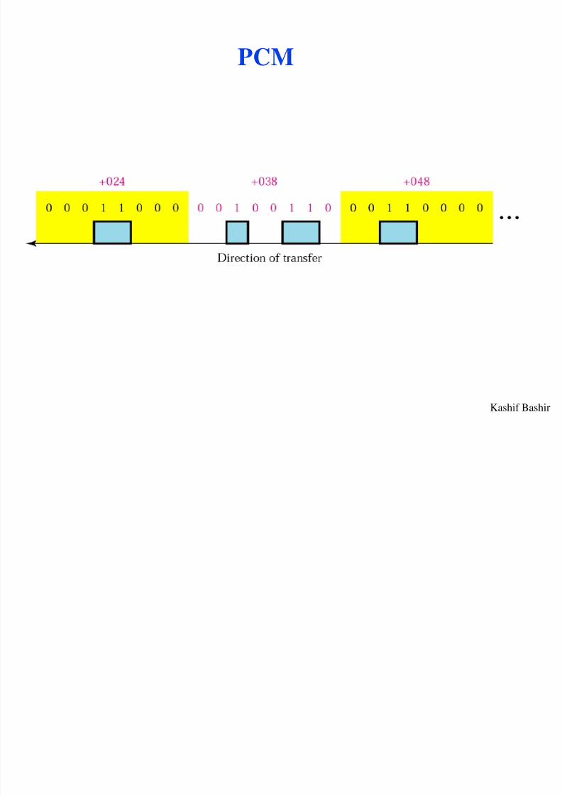
PCM
8/4/2019 Digital Transmission 4
http://slidepdf.com/reader/full/digital-transmission-4 45/65
Kashif Bashir
From Analog to PCM
8/4/2019 Digital Transmission 4
http://slidepdf.com/reader/full/digital-transmission-4 46/65
Kashif Bashir 4.46
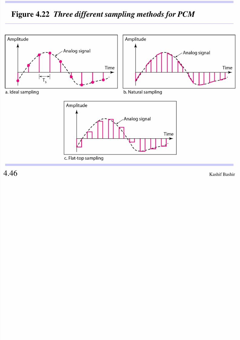
Figure 4.22 Three different sampling methods for PCM
8/4/2019 Digital Transmission 4
http://slidepdf.com/reader/full/digital-transmission-4 47/65
Kashif Bashir 4.47
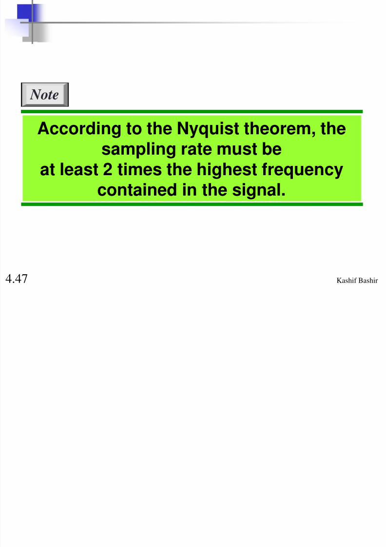
According to the Nyquist theorem, thesampling rate must be
at least 2 times the highest frequencycontained in the signal.
Note

8/4/2019 Digital Transmission 4
http://slidepdf.com/reader/full/digital-transmission-4 48/65
Kashif Bashir 4.48
Figure 4.23 Nyquist sampling rate for low-pass and bandpass signals
E l

8/4/2019 Digital Transmission 4
http://slidepdf.com/reader/full/digital-transmission-4 49/65
Kashif Bashir
Example
What sampling rate is needed for a signal with a
bandwidth of 10,000 Hz (1000 to 11,000 Hz)?
Solution
The sampling rate must be twice the highest frequency inthe signal:
Sampling rate = 2 x (11,000) = 22,000 samples/s
E l
8/4/2019 Digital Transmission 4
http://slidepdf.com/reader/full/digital-transmission-4 50/65
Kashif Bashir
Example
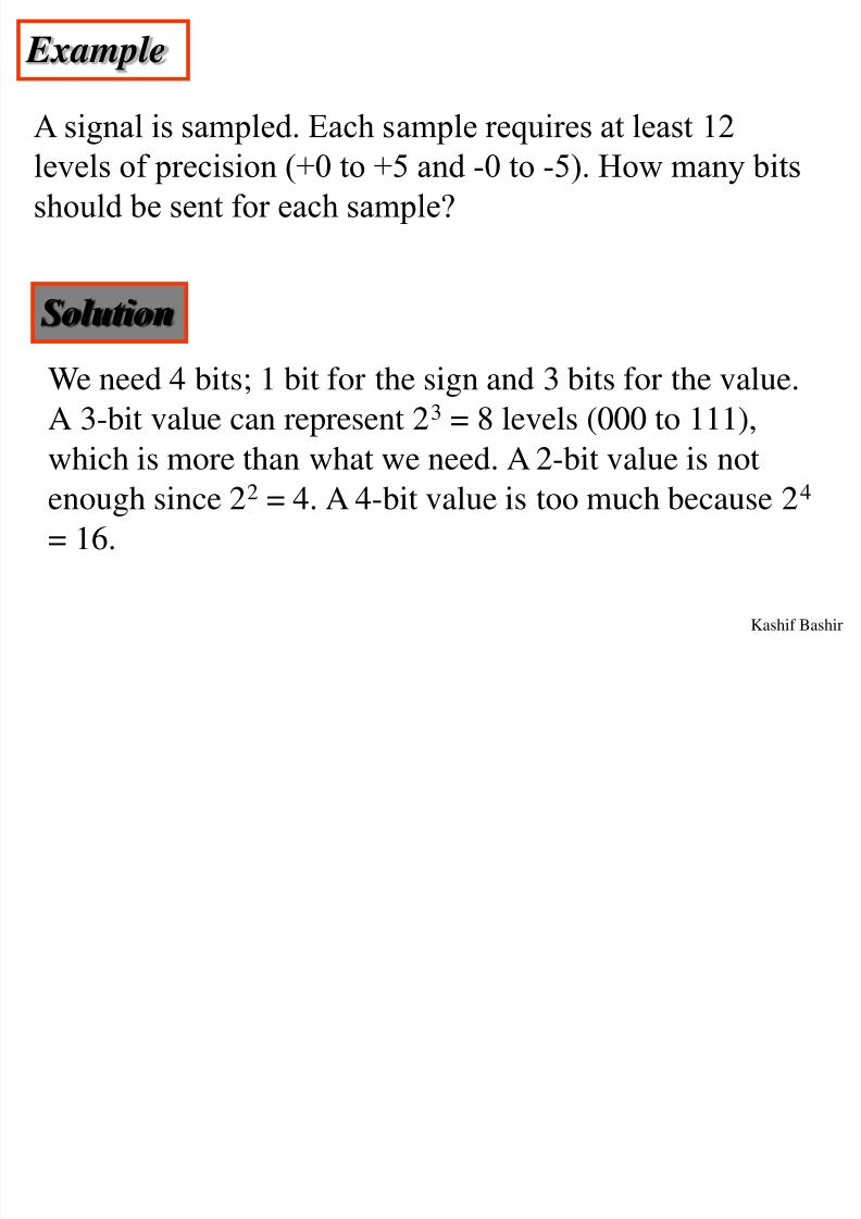
A signal is sampled. Each sample requires at least 12
levels of precision (+0 to +5 and -0 to -5). How many bitsshould be sent for each sample?
Solution
We need 4 bits; 1 bit for the sign and 3 bits for the value.
A 3-bit value can represent 23 = 8 levels (000 to 111),
which is more than what we need. A 2-bit value is notenough since 22 = 4. A 4-bit value is too much because 24
= 16.
E l
8/4/2019 Digital Transmission 4
http://slidepdf.com/reader/full/digital-transmission-4 51/65
Kashif Bashir
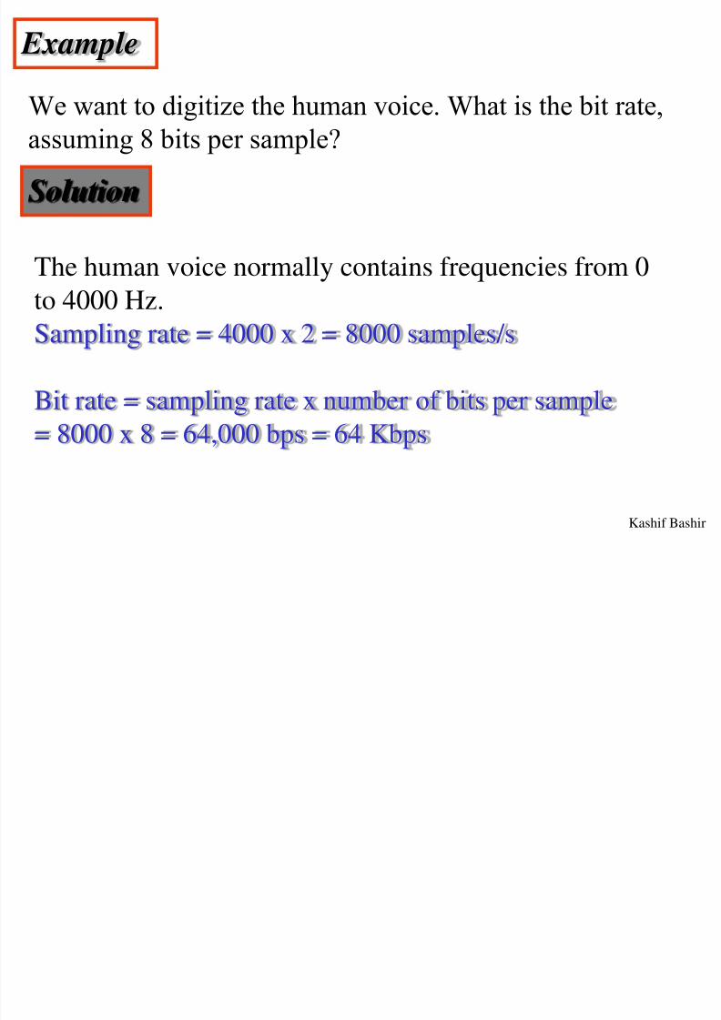
Example
We want to digitize the human voice. What is the bit rate,
assuming 8 bits per sample?
Solution
The human voice normally contains frequencies from 0to 4000 Hz.
Sampling rate = 4000 x 2 = 8000 samples/s
Bit rate = sampling rate x number of bits per sample
= 8000 x 8 = 64,000 bps = 64 Kbps

8/4/2019 Digital Transmission 4
http://slidepdf.com/reader/full/digital-transmission-4 52/65
Kashif Bashir 4.52
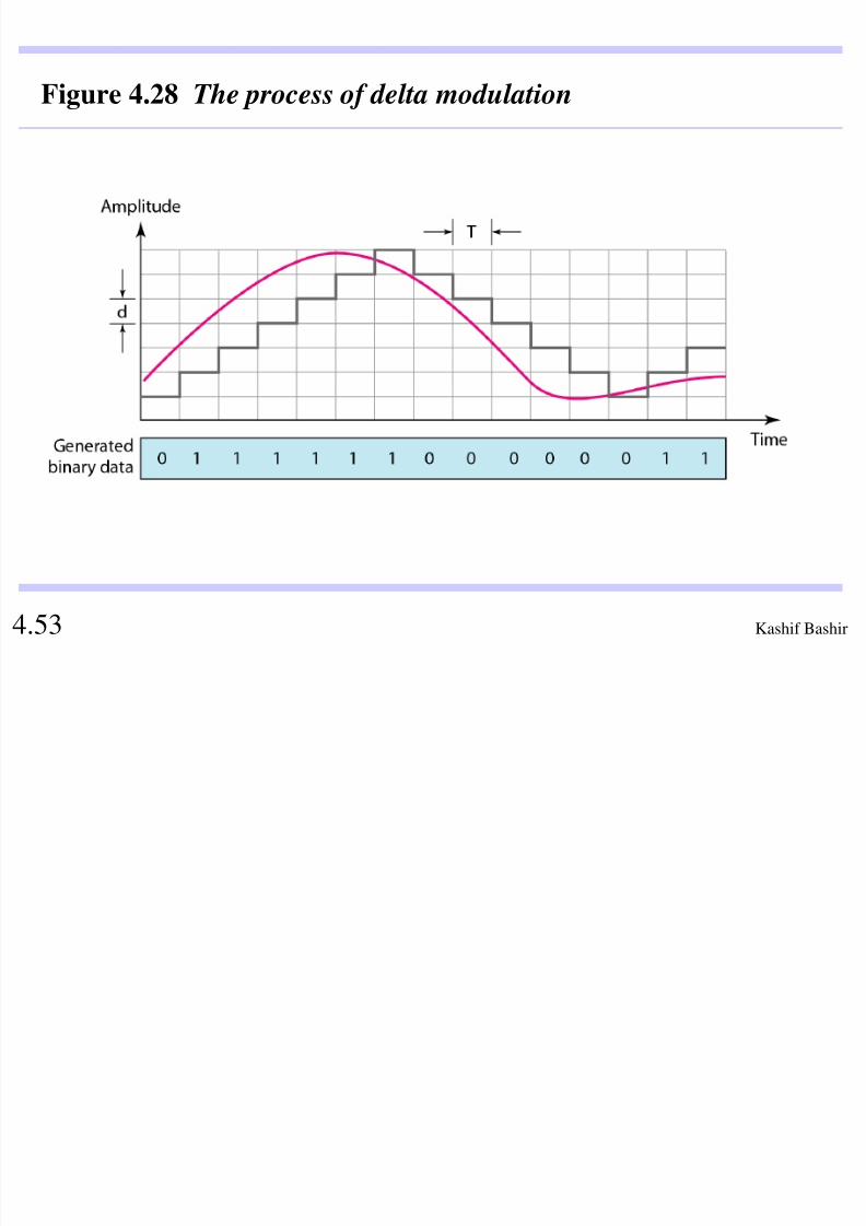
PCM is a very complex technique. Othertechniques have been developed to reducethe complexity of PCM. The simplest isdelta modulation . DM finds the change
from the previous sample, used fortransmission of voice information wherequality is not of primary importance.
Note
8/4/2019 Digital Transmission 4
http://slidepdf.com/reader/full/digital-transmission-4 53/65
Kashif Bashir 4.53
Figure 4.28 The process of delta modulation
8/4/2019 Digital Transmission 4
http://slidepdf.com/reader/full/digital-transmission-4 54/65
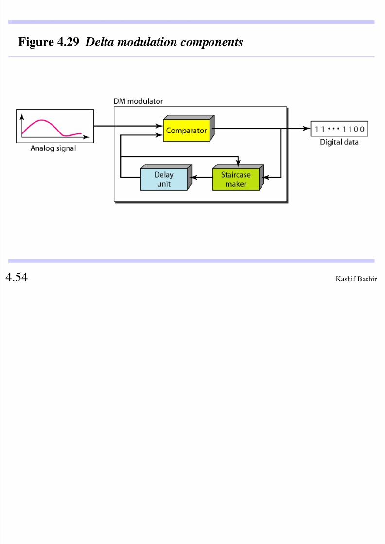
Kashif Bashir 4.54
Figure 4.29 Delta modulation components
8/4/2019 Digital Transmission 4
http://slidepdf.com/reader/full/digital-transmission-4 55/65
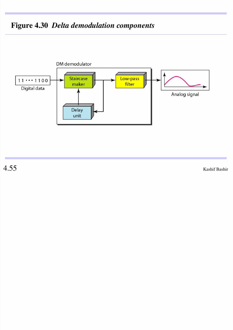
Kashif Bashir 4.55
Figure 4.30 Delta demodulation components

8/4/2019 Digital Transmission 4
http://slidepdf.com/reader/full/digital-transmission-4 56/65
Kashif Bashir 4.56
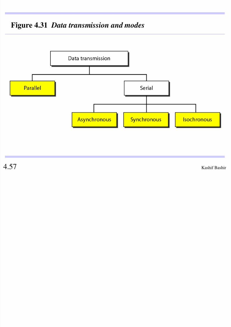
3 TRANSMISSION MODES
The transmission of binary data across a link can be accomplished in either parallel or serial mode. In
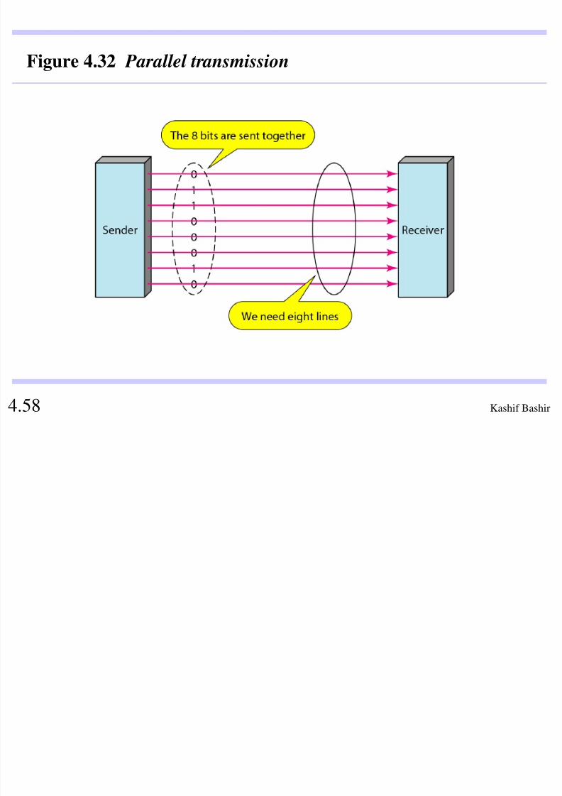
parallel mode, multiple bits are sent with each clock
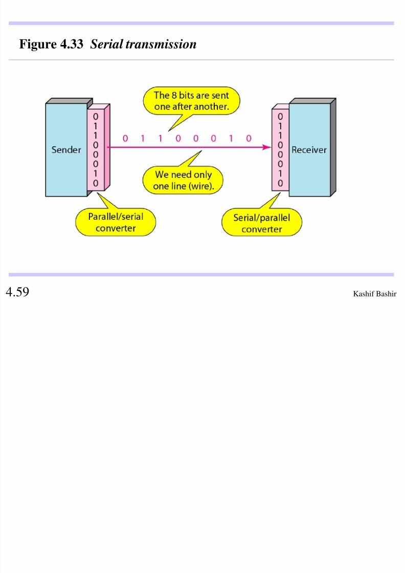
tick. In serial mode, 1 bit is sent with each clock tick.
While there is only one way to send parallel data, there
are three subclasses of serial transmission:
asynchronous, synchronous, and isochronous.
Parallel Transmission
Serial Transmission
Topics discussed in this section:
8/4/2019 Digital Transmission 4
http://slidepdf.com/reader/full/digital-transmission-4 57/65
Kashif Bashir 4.57
Figure 4.31 Data transmission and modes
8/4/2019 Digital Transmission 4
http://slidepdf.com/reader/full/digital-transmission-4 58/65
Kashif Bashir 4.58
Figure 4.32 Parallel transmission
8/4/2019 Digital Transmission 4
http://slidepdf.com/reader/full/digital-transmission-4 59/65
Kashif Bashir 4.59
Figure 4.33 Serial transmission

8/4/2019 Digital Transmission 4
http://slidepdf.com/reader/full/digital-transmission-4 60/65
Kashif Bashir 4.60
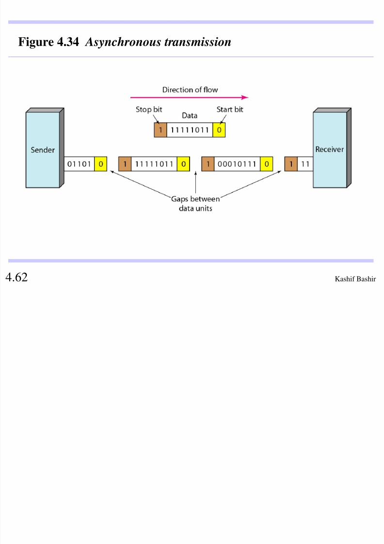
In asynchronous transmission, we send1 start bit (0) at the beginning and 1 ormore stop bits (1s) at the end of each
byte. There may be a gap between
each byte.
Note
8/4/2019 Digital Transmission 4
http://slidepdf.com/reader/full/digital-transmission-4 61/65
Kashif Bashir 4.61
Asynchronous here means“asynchronous at the byte level,” but the bits are still synchronized;
their durations are the same.
Note
8/4/2019 Digital Transmission 4
http://slidepdf.com/reader/full/digital-transmission-4 62/65
Kashif Bashir 4.62
Figure 4.34 Asynchronous transmission
8/4/2019 Digital Transmission 4
http://slidepdf.com/reader/full/digital-transmission-4 63/65
Kashif Bashir 4.63
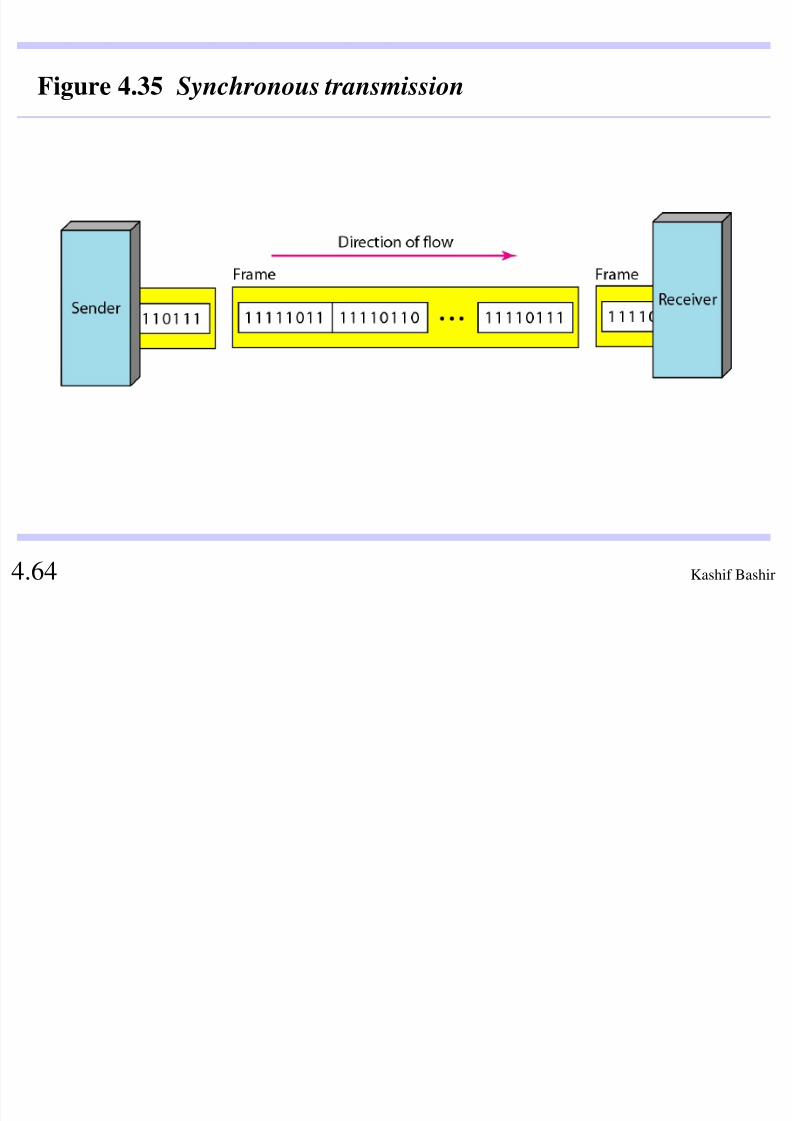
In synchronous transmission, we sendbits one after another without start or
stop bits or gaps. It is the responsibilityof the receiver to group the bits.
Note
8/4/2019 Digital Transmission 4
http://slidepdf.com/reader/full/digital-transmission-4 64/65
Kashif Bashir 4.64
Figure 4.35 Synchronous transmission
Isochronous

8/4/2019 Digital Transmission 4
http://slidepdf.com/reader/full/digital-transmission-4 65/65
In real-time audio and video, in which uneven delays betweenframes are not acceptable, synchronous transmission fails. For
example, TV images are broadcast at the rate of 30 images per
second; they must be viewed at the same rate. If each image is
sent by using one or more flames, there should be no delays
between frames. For this type of application, synchronization
between characters is not enough; the entire stream of bits must
be synchronized. The isochronous transmission guarantees that
the data arrive at a fixed rate.