Embed Size (px)
Citation preview
Computer Networks 1
Chapter 4
DigitalTransmission
Computer Networks 2
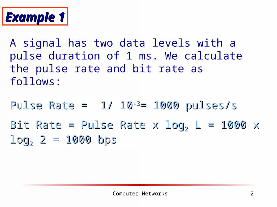
Example 1Example 1
A signal has two data levels with a pulse duration of 1 ms. We calculate the pulse rate and bit rate as follows:
Pulse Rate = 1/ 10Pulse Rate = 1/ 10-3-3= 1000 pulses/s= 1000 pulses/s
Bit Rate = Pulse Rate x logBit Rate = Pulse Rate x log22 L = 1000 x log L = 1000 x log22 2 = 1000 bps 2 = 1000 bps
Computer Networks 3
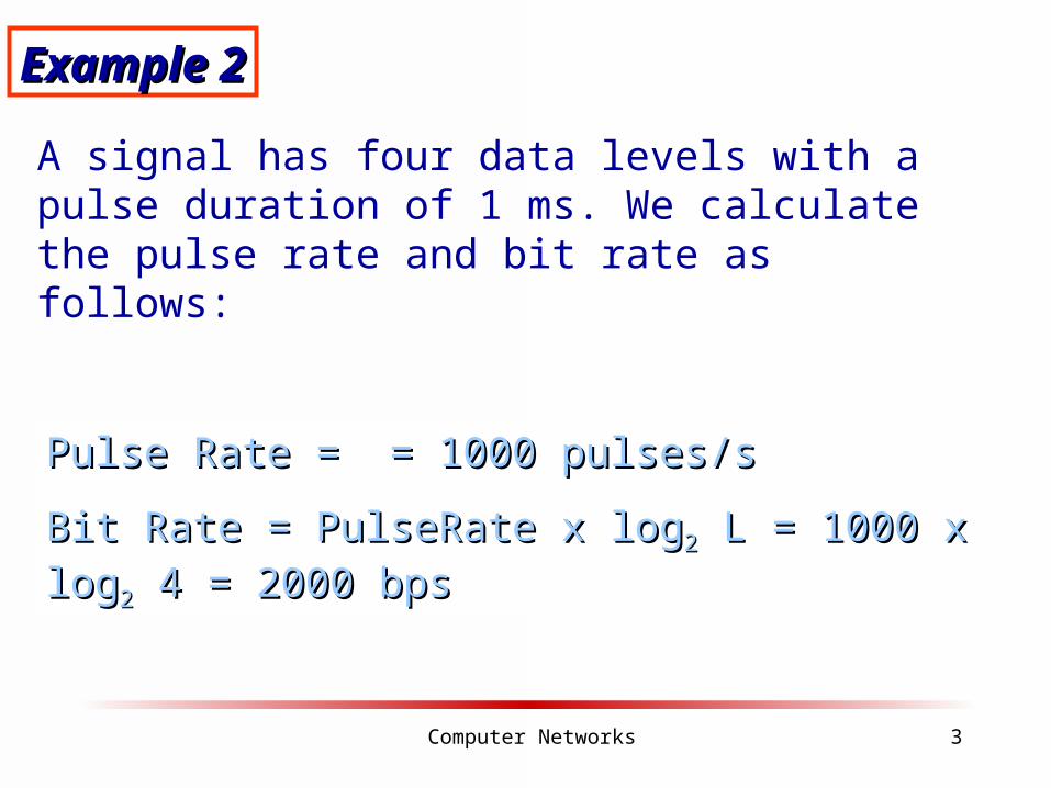
Example 2Example 2
A signal has four data levels with a pulse duration of 1 ms. We calculate the pulse rate and bit rate as follows:
Pulse Rate = = 1000 pulses/sPulse Rate = = 1000 pulses/s
Bit Rate = PulseRate x logBit Rate = PulseRate x log22 L = 1000 x log L = 1000 x log22 4 = 2000 bps 4 = 2000 bps

Computer Networks 4
Figure 4.3 DC component
Computer Networks 5
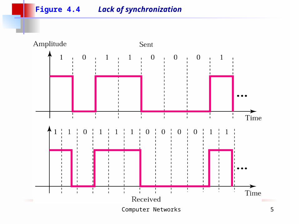
Figure 4.4 Lack of synchronization
Computer Networks 6
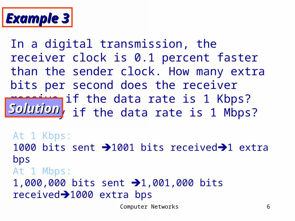
Example 3Example 3
In a digital transmission, the receiver clock is 0.1 percent faster than the sender clock. How many extra bits per second does the receiver receive if the data rate is 1 Kbps? How many if the data rate is 1 Mbps?
SolutionSolution
At 1 Kbps:1000 bits sent 1001 bits received1 extra bpsAt 1 Mbps: 1,000,000 bits sent 1,001,000 bits received1000 extra bps

Computer Networks 7
Figure 4.4 Lack of synchronization

Computer Networks 8
Example 3Example 3
In a digital transmission, the receiver clock is 0.1 percent faster than the sender clock. How many extra bits per second does the receiver receive if the data rate is 1 Kbps? How many if the data rate is 1 Mbps?
SolutionSolution
At 1 Kbps:1000 bits sent 1001 bits received1 extra bpsAt 1 Mbps: 1,000,000 bits sent 1,001,000 bits received1000 extra bps
Computer Networks 9
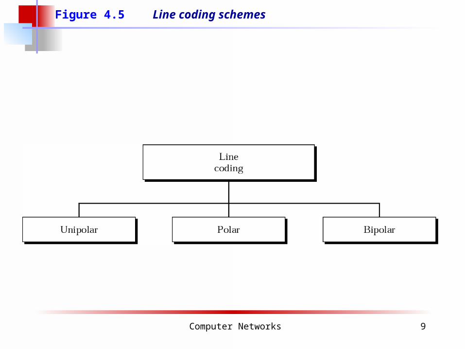
Figure 4.5 Line coding schemes
Computer Networks 10
Unipolar encoding uses only one voltage level.
Note:Note:
Computer Networks 11
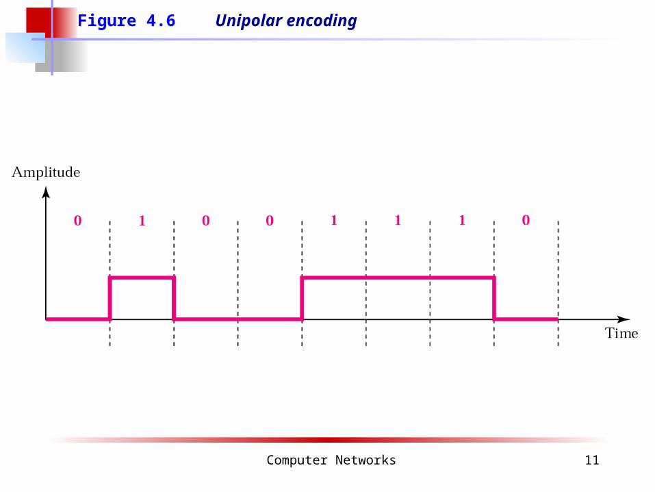
Figure 4.6 Unipolar encoding
Computer Networks 12
Polar encoding uses two voltage levels Polar encoding uses two voltage levels (positive and negative).(positive and negative).
Note:Note:
Computer Networks 13
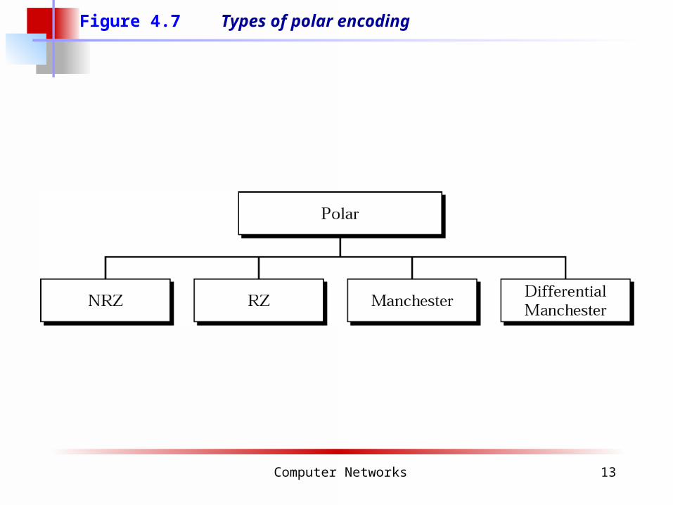
Figure 4.7 Types of polar encoding
Computer Networks 14
In NRZ-L the level of the signal is In NRZ-L the level of the signal is dependent upon the state of the bit.dependent upon the state of the bit.
Note:Note:
Computer Networks 15
In NRZ-I the signal is inverted if a 1 is In NRZ-I the signal is inverted if a 1 is encountered.encountered.
Note:Note:
Computer Networks 16
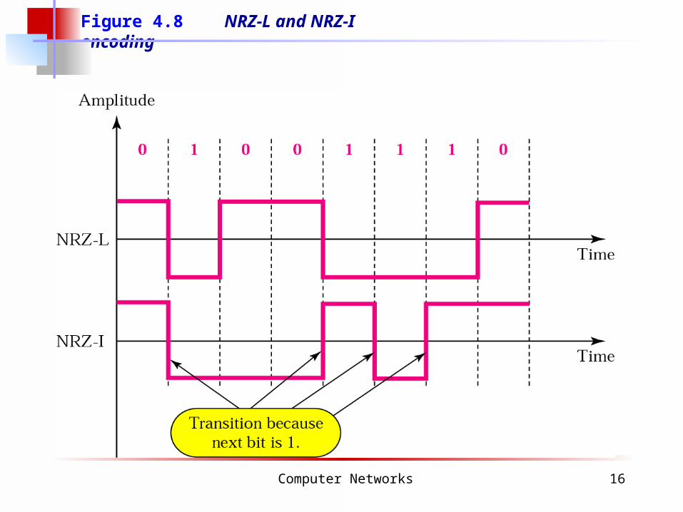
Figure 4.8 NRZ-L and NRZ-I encoding
Computer Networks 17
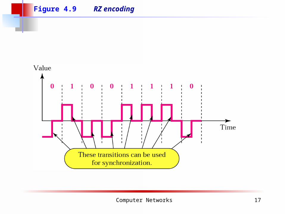
Figure 4.9 RZ encoding
Computer Networks 18
A good encoded digital signal must A good encoded digital signal must contain a provision for contain a provision for
synchronization.synchronization.
Note:Note:
Computer Networks 19
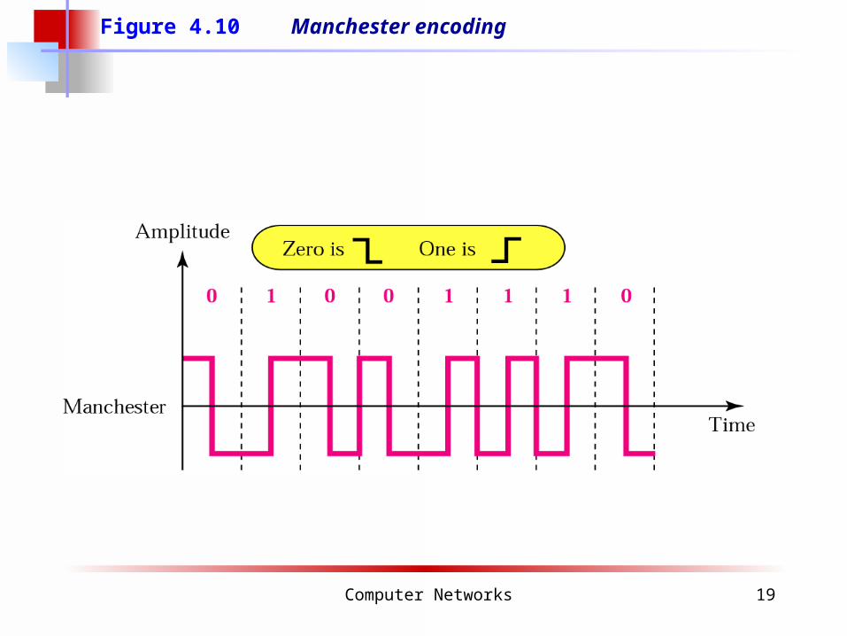
Figure 4.10 Manchester encoding
Computer Networks 20
In Manchester encoding, the In Manchester encoding, the transition at the middle of the bit is transition at the middle of the bit is
used for both synchronization and bit used for both synchronization and bit representation.representation.
Note:Note:
Computer Networks 21
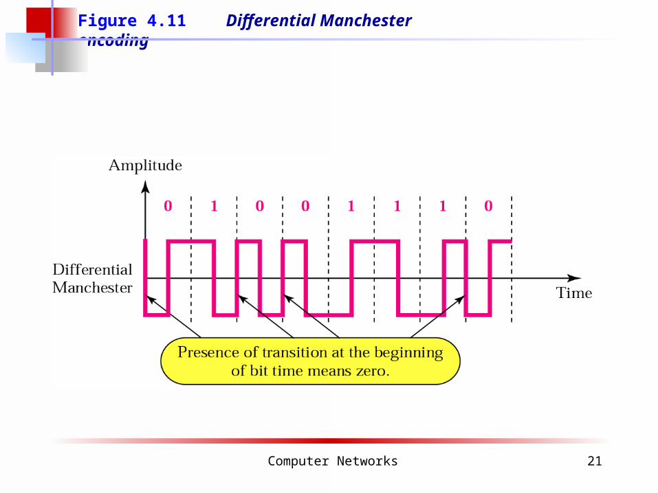
Figure 4.11 Differential Manchester encoding
Computer Networks 22
In differential Manchester encoding, In differential Manchester encoding, the transition at the middle of the bit is the transition at the middle of the bit is
used only for synchronization. used only for synchronization. The bit representation is defined by the The bit representation is defined by the
inversion or noninversion at the inversion or noninversion at the beginning of the bit.beginning of the bit.
Note:Note:
Computer Networks 23
In bipolar encoding, we use three In bipolar encoding, we use three levels: positive, zero, levels: positive, zero,
and negative.and negative.
Note:Note:
Computer Networks 24
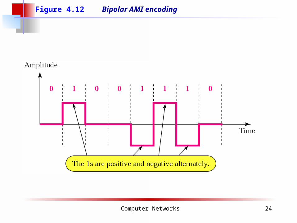
Figure 4.12 Bipolar AMI encoding
Computer Networks 25
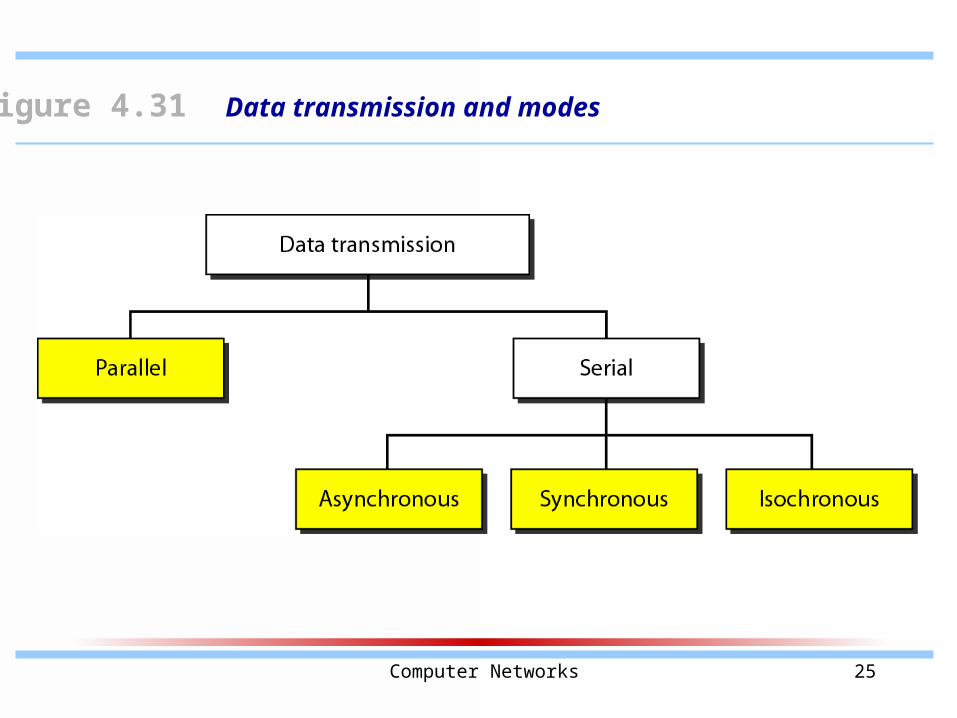
Figure 4.31 Data transmission and modes
Computer Networks 26
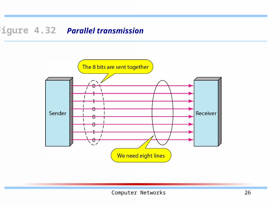
Figure 4.32 Parallel transmission
Computer Networks 27
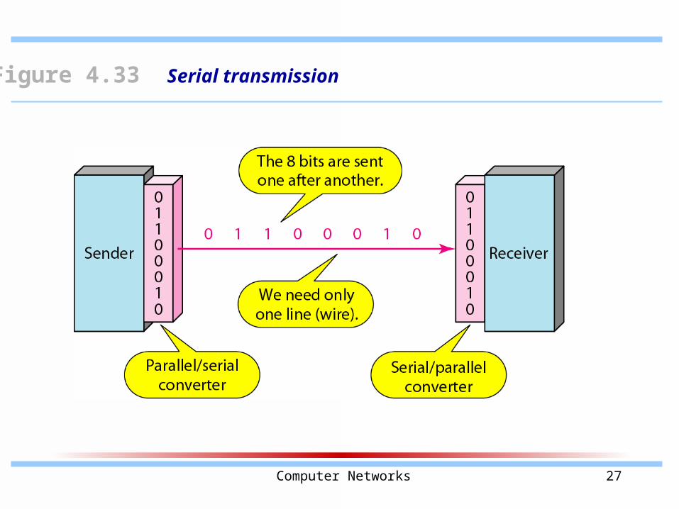
Figure 4.33 Serial transmission
Computer Networks 28
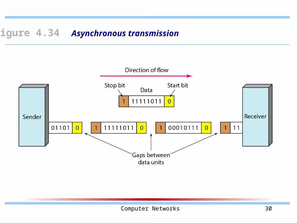
In asynchronous transmission, we send 1 start bit (0) at the beginning and 1 or more stop bits (1s) at the end of each
byte. There may be a gap between each byte.
Note
Computer Networks 29
Asynchronous here means “asynchronous at the byte level,”
but the bits are still synchronized; their durations are the same.
Note
Computer Networks 30
Figure 4.34 Asynchronous transmission
Computer Networks 31
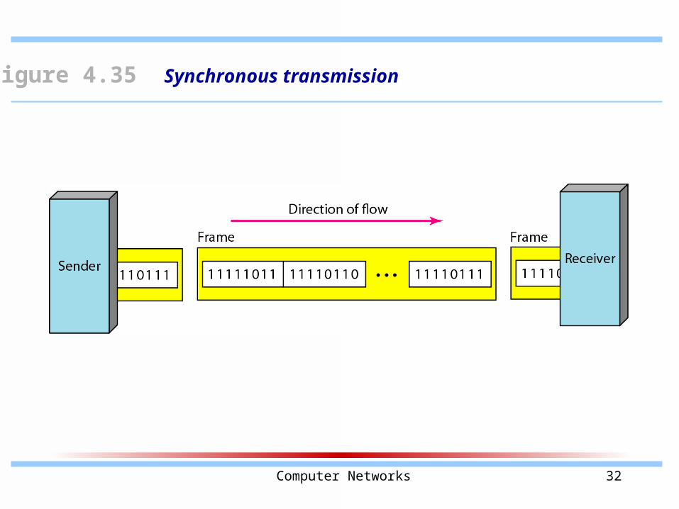
In synchronous transmission, we send bits one after another without start or
stop bits or gaps. It is the responsibility of the receiver to group the bits.
Note
Computer Networks 32
Figure 4.35 Synchronous transmission
Computer Networks 33
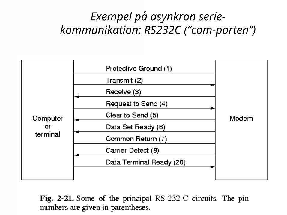
Exempel på asynkron serie-kommunikation: RS232C (”com-
porten”)