Embed Size (px)
Citation preview
PN 4345349 July 2013 © 2013 Fluke Corporation. All rights reserved. Specifications are subject to change without notice. All product names are trademarks of their respective companies.
101 Digital Multimeter
Users Manual
LIMITED WARRANTY AND LIMITATION OF LIABILITY This Fluke product will be free from defects in material and workmanship for one year from the date of purchase. This warranty does not cover fuses, disposable batteries, or damage from accident, neglect, misuse, alteration, contamination, or abnormal conditions of operation or handling. Resellers are not authorized to extend any other warranty on Fluke’s behalf. To obtain service during the warranty period, contact your nearest Fluke authorized service center to obtain return authorization information, then send the product to that Service Center with a description of the problem. THIS WARRANTY IS YOUR ONLY REMEDY. NO OTHER WARRANTIES, SUCH AS FITNESS FOR A PARTICULAR PURPOSE, ARE EXPRESSED OR IMPLIED. FLUKE IS NOT LIABLE FOR ANY SPECIAL, INDIRECT, INCIDENTAL OR CONSEQUENTIAL DAMAGES OR LOSSES, ARISING FROM ANY CAUSE OR THEORY. Since some states or countries do not allow the exclusion or limitation of an implied warranty or of incidental or consequential damages, this limitation of liability may not apply to you.
Fluke Corporation P.O. Box 9090 Everett, WA 98206-9090 U.S.A.
Fluke Europe B.V. P.O. Box 1186 5602 BD Eindhoven The Netherlands
11/99
i
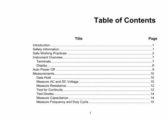
Table of Contents
Title Page
Introduction ................................................................................................................. 1 Safety Information ...................................................................................................... 1 Safe Working Practices .............................................................................................. 2 Instrument Overview................................................................................................... 7
Terminals ................................................................................................................ 7 Display .................................................................................................................... 8
Auto Power Off ........................................................................................................... 9 Measurements .......................................................................................................... 10
Data Hold ............................................................................................................. 10 Measure AC and DC Voltage ............................................................................... 10 Measure Resistance ............................................................................................. 12 Test for Continuity ................................................................................................ 12 Test Diodes .......................................................................................................... 14 Measure Capacitance .......................................................................................... 14 Measure Frequency and Duty Cycle .................................................................... 15
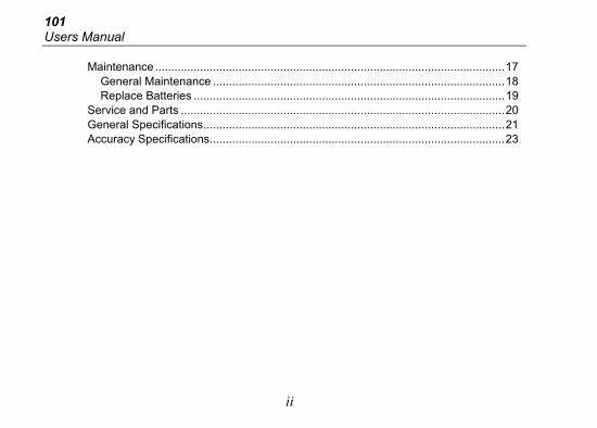
101 Users Manual
ii
Maintenance ............................................................................................................. 17 General Maintenance ........................................................................................... 18 Replace Batteries ................................................................................................. 19
Service and Parts ..................................................................................................... 20 General Specifications .............................................................................................. 21 Accuracy Specifications ............................................................................................ 23
1
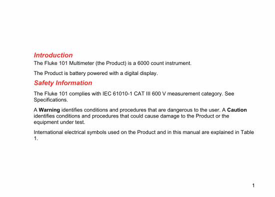
Introduction The Fluke 101 Multimeter (the Product) is a 6000 count instrument.
The Product is battery powered with a digital display.
Safety Information
The Fluke 101 complies with IEC 61010-1 CAT III 600 V measurement category. See Specifications.
A Warning identifies conditions and procedures that are dangerous to the user. A Caution identifies conditions and procedures that could cause damage to the Product or the equipment under test.
International electrical symbols used on the Product and in this manual are explained in Table 1.
101 Users Manual
2
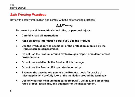
Safe Working Practices
Review the safety information and comply with the safe working practices.
Warning
To prevent possible electrical shock, fire, or personal injury:
• Carefully read all instructions.
• Read all safety information before you use the Product.
• Use the Product only as specified, or the protection supplied by the Product can be compromised.
• Do not use the Product around explosive gas, vapor, or in damp or wet environments.
• Do not use and disable the Product if it is damaged.
• Do not use the Product if it operates incorrectly.
• Examine the case before you use the Product. Look for cracks or missing plastic. Carefully look at the insulation around the terminals.
• Use only correct measurement category (CAT), voltage, and amperage rated probes, test leads, and adapters for the measurement.
Multimeter Safe Working Practices
3
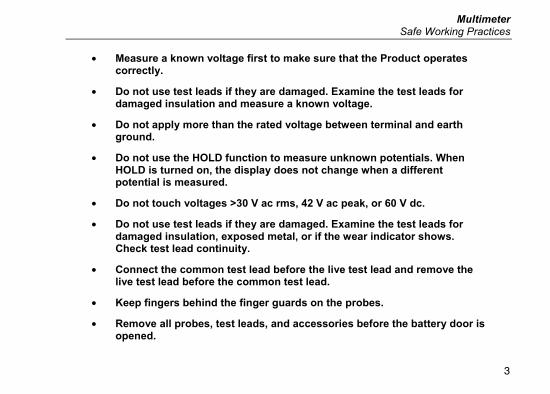
• Measure a known voltage first to make sure that the Product operates correctly.
• Do not use test leads if they are damaged. Examine the test leads for damaged insulation and measure a known voltage.
• Do not apply more than the rated voltage between terminal and earth ground.
• Do not use the HOLD function to measure unknown potentials. When HOLD is turned on, the display does not change when a different potential is measured.
• Do not touch voltages >30 V ac rms, 42 V ac peak, or 60 V dc.
• Do not use test leads if they are damaged. Examine the test leads for damaged insulation, exposed metal, or if the wear indicator shows. Check test lead continuity.
• Connect the common test lead before the live test lead and remove the live test lead before the common test lead.
• Keep fingers behind the finger guards on the probes.
• Remove all probes, test leads, and accessories before the battery door is opened.
101 Users Manual
4
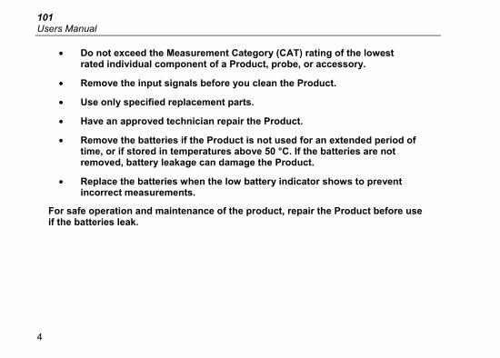
• Do not exceed the Measurement Category (CAT) rating of the lowest rated individual component of a Product, probe, or accessory.
• Remove the input signals before you clean the Product.
• Use only specified replacement parts.
• Have an approved technician repair the Product.
• Remove the batteries if the Product is not used for an extended period of time, or if stored in temperatures above 50 °C. If the batteries are not removed, battery leakage can damage the Product.
• Replace the batteries when the low battery indicator shows to prevent incorrect measurements.
For safe operation and maintenance of the product, repair the Product before use if the batteries leak.
Multimeter Safe Working Practices
5
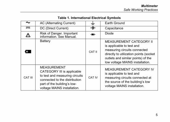
Table 1. International Electrical Symbols
AC (Alternating Current) Earth Ground
DC (Direct Current) Capacitance
Risk of Danger. Important information. See Manual. Diode
Battery
CAT II
MEASUREMENT CATEGORY II is applicable to test and measuring circuits connected directly to utilization points (socket outlets and similar points) of the low voltage MAINS installation.
CAT III
MEASUREMENT CATEGORY III is applicable to test and measuring circuits connected to the distribution part of the building’s low-voltage MAINS installation.
CAT IV
MEASUREMENT CATEGORY IV is applicable to test and measuring circuits connected at the source of the building’s low voltage MAINS installation.
101 Users Manual
6
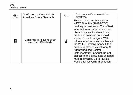
Conforms to relevant North American Safety Standards.
Conforms to European Union directives.
Conforms to relevant South Korean EMC Standards.
This product complies with the WEEE Directive (2002/96/EC) marking requirements. The affixed label indicates that you must not discard this electrical/electronic product in domestic household waste. Product Category: With reference to the equipment types in the WEEE Directive Annex I, this product is classed as category 9 "Monitoring and Control Instrumentation" product. Do not dispose of this product as unsorted municipal waste. Go to Fluke’s website for recycling information.
Multimeter Instrument Overview
7
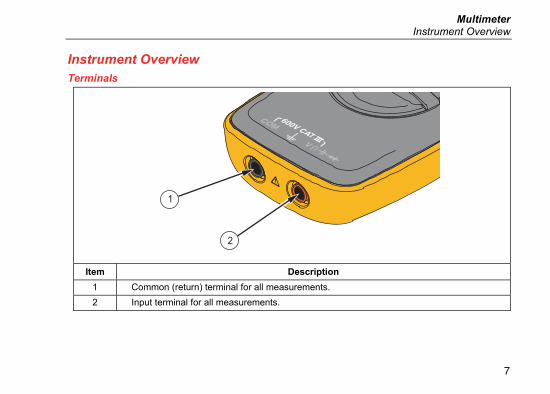
Instrument Overview Terminals
1
2
Item Description
1 Common (return) terminal for all measurements.
2 Input terminal for all measurements.
101 Users Manual
8
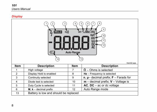
Display
1 2 3 4 5 6 7 8
9
10
11
12
1314
hkm02.eps
Item Description Item Description1 High voltage 7 – Ohms is selected2 Display Hold is enabled 8 Hz – Frequency is selected
3 Continuity selected 9 n, μ– decimal prefix; F – Farads for it4 Diode test is selected 10 m – decimal prefix; V – Voltage is
5 Duty Cycle is selected 11 AC, DC – ac or dc voltage
6 M, k – decimal prefix 12 Auto Range mode
13 Battery is low and should be replaced
Multimeter Auto Power Off
9
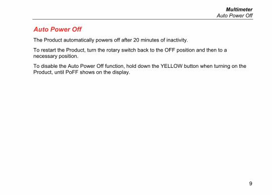
Auto Power Off
The Product automatically powers off after 20 minutes of inactivity.
To restart the Product, turn the rotary switch back to the OFF position and then to a necessary position.
To disable the Auto Power Off function, hold down the YELLOW button when turning on the Product, until PoFF shows on the display.
101 Users Manual
10
Measurements Data Hold
Warning
To prevent possible electrical shock, fire or personal injury, do not use the HOLD function to measure unknown potentials. When HOLD is turned on, the display does not change when a different potential is measured.
To hold the present reading, push . Push again to resume normal operation.
Measure AC and DC Voltage
To measure AC and DC voltage:
1. Choose ac or dc by turning the rotary switch to , , or .
2. Connect the red test lead to the terminal and the black test lead to the COM terminal.
3. Measure the voltage by touching the probes to the correct test points of the circuit.
4. Read the measured voltage on the display.
Multimeter Measurements
11
m
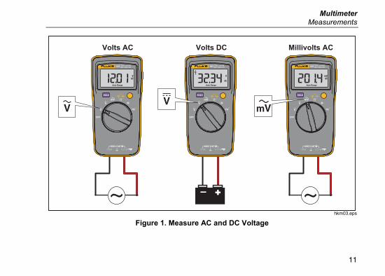
Volts AC Volts DC Millivolts AC
hkm03.eps
Figure 1. Measure AC and DC Voltage

101 Users Manual
12
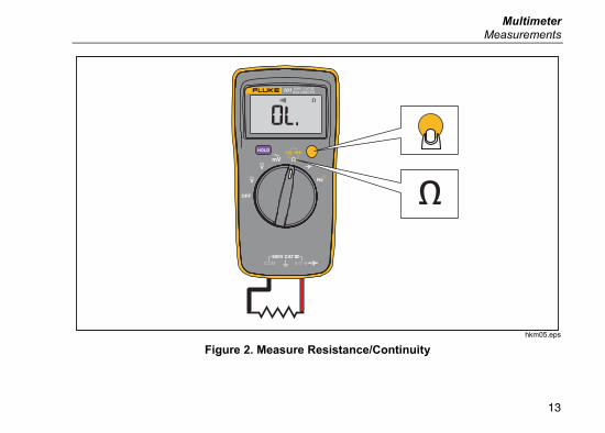
Measure Resistance
1. Turn the rotary switch to . Make sure power is disconnected from the circuit to be measured.
2. Connect the red test lead to the terminal and the black test lead to the COM terminal.
3. Measure the resistance by touching the probes to the desired test points of the circuit.
4. Read the measured resistance on the display.
Test for Continuity
With the resistance mode selected, push the YELLOW button once to activate the continuity mode. If the resistance is <70 Ω, the beeper will sound continuously, designating a short circuit. If the Product reads , the circuit is open.
Multimeter Measurements
13
m
hkm05.eps
Figure 2. Measure Resistance/Continuity
101 Users Manual
14
Test Diodes
1. Turn the rotary switch to .
2. Push the YELLOW button twice to activate the diode test mode.
3. Connect the red test lead to the terminal and the black test lead to the COM terminal.
4. Connect the red probe to the anode and the black test lead to the cathode of the diode being tested.
5. Read the forward bias voltage value on the display.
6. If the polarity of the test leads is reversed with diode polarity, the display reading shows . This can be used to distinguish the anode and cathode sides of a diode.
Measure Capacitance
1. Turn the rotary switch to .
2. Connect the red test lead to the terminal and the black test lead to the COM terminal.
3. Touch the probes to the capacitor leads.
4. After allowing the reading to stabilize (10 seconds at most), read the capacitance value on the display.
Multimeter Measurements
15
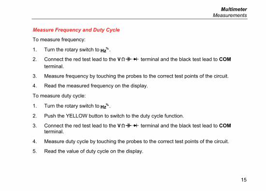
Measure Frequency and Duty Cycle
To measure frequency:
1. Turn the rotary switch to .
2. Connect the red test lead to the terminal and the black test lead to COM terminal.
3. Measure frequency by touching the probes to the correct test points of the circuit.
4. Read the measured frequency on the display.
To measure duty cycle:
1. Turn the rotary switch to .
2. Push the YELLOW button to switch to the duty cycle function.
3. Connect the red test lead to the terminal and the black test lead to COM terminal.
4. Measure duty cycle by touching the probes to the correct test points of the circuit.
5. Read the value of duty cycle on the display.
101 Users Manual
16
m
hkm04.eps
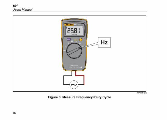
Figure 3. Measure Frequency/Duty Cycle
Multimeter Maintenance
17
Maintenance Beyond replacing batteries, do not attempt to repair or service your Meter unless you are qualified to do so and have the relevant calibration, performance test, and service instructions. The recommended calibration cycle is 12 months.
Warning
To prevent possible electrical shock, fire, or personal injury:
• Remove the input signals before you clean the Product.
• Use only specified replacement parts.
• Have an approved technician repair the Product.
For safe operation and maintenance of the Product, repair the Product before use if the batteries leak.
101 Users Manual
18
General Maintenance
Periodically wipe the case with a damp cloth and mild detergent. Do not use abrasives or solvents. Dirt or moisture in the terminals can affect readings.
To clean the terminals:
1. Turn the Product off and remove the test leads.
2. Shake out any dirt that may be in the terminals.
3. Soak a new swab with isopropyl alcohol and work around the inside of each input terminal.
4. Use a new swab to apply a light coat of fine machine oil to the inside of each terminal.
Multimeter Maintenance
19
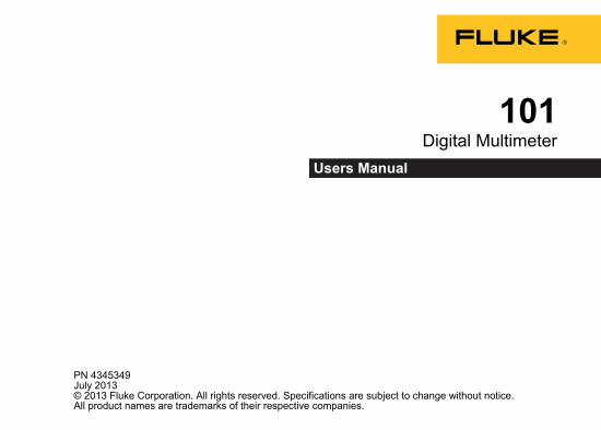
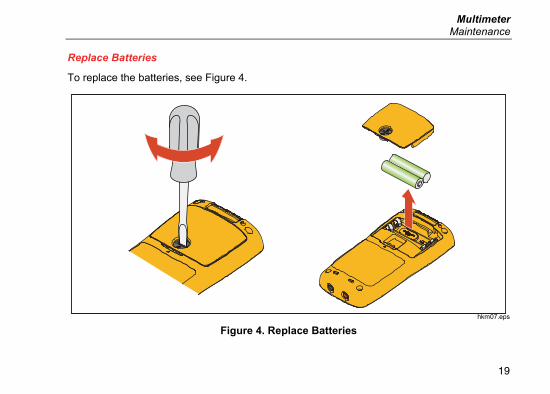
Replace Batteries
To replace the batteries, see Figure 4.
hkm07.eps
Figure 4. Replace Batteries
101 Users Manual
20
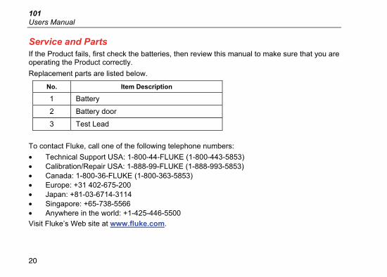
Service and Parts If the Product fails, first check the batteries, then review this manual to make sure that you are operating the Product correctly.
Replacement parts are listed below.
No. Item Description
1 Battery
2 Battery door
3 Test Lead
To contact Fluke, call one of the following telephone numbers:
• Technical Support USA: 1-800-44-FLUKE (1-800-443-5853) • Calibration/Repair USA: 1-888-99-FLUKE (1-888-993-5853) • Canada: 1-800-36-FLUKE (1-800-363-5853) • Europe: +31 402-675-200 • Japan: +81-03-6714-3114 • Singapore: +65-738-5566 • Anywhere in the world: +1-425-446-5500
Visit Fluke’s Web site at www.fluke.com.
Multimeter General Specifications
21
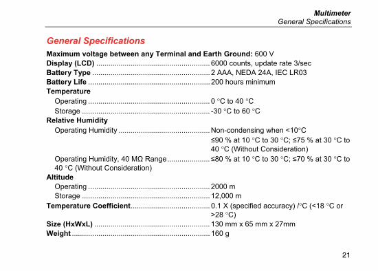
General Specifications
Maximum voltage between any Terminal and Earth Ground: 600 V Display (LCD) ........................................................ 6000 counts, update rate 3/sec Battery Type .......................................................... 2 AAA, NEDA 24A, IEC LR03 Battery Life ............................................................ 200 hours minimum Temperature
Operating ............................................................ 0 °C to 40 °C Storage ............................................................... -30 °C to 60 °C
Relative Humidity Operating Humidity ............................................. Non-condensing when <10°C
≤90 % at 10 °C to 30 °C; ≤75 % at 30 °C to 40 °C (Without Consideration)
Operating Humidity, 40 MΩ Range ..................... ≤80 % at 10 °C to 30 °C; ≤70 % at 30 °C to 40 °C (Without Consideration)
Altitude Operating ............................................................ 2000 m Storage ............................................................... 12,000 m
Temperature Coefficient ....................................... 0.1 X (specified accuracy) /°C (<18 °C or >28 °C)
Size (HxWxL) ......................................................... 130 mm x 65 mm x 27mm Weight .................................................................... 160 g
101 Users Manual
22
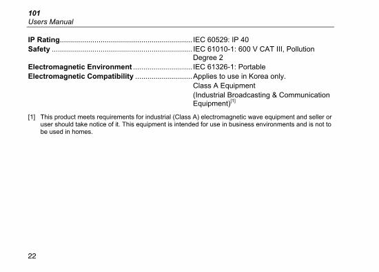
IP Rating................................................................. IEC 60529: IP 40 Safety ..................................................................... IEC 61010-1: 600 V CAT III, Pollution
Degree 2 Electromagnetic Environment ............................. IEC 61326-1: Portable Electromagnetic Compatibility ............................ Applies to use in Korea only.
Class A Equipment (Industrial Broadcasting & Communication Equipment)[1]
[1] This product meets requirements for industrial (Class A) electromagnetic wave equipment and seller or user should take notice of it. This equipment is intended for use in business environments and is not to be used in homes.
Multimeter Accuracy Specifications
23
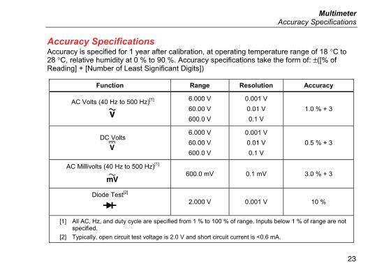
Accuracy Specifications Accuracy is specified for 1 year after calibration, at operating temperature range of 18 °C to 28 °C, relative humidity at 0 % to 90 %. Accuracy specifications take the form of: ±([% of Reading] + [Number of Least Significant Digits])
Function Range Resolution Accuracy
AC Volts (40 Hz to 500 Hz)[1]
6.000 V
60.00 V
600.0 V
0.001 V
0.01 V
0.1 V
1.0 % + 3
DC Volts
6.000 V
60.00 V
600.0 V
0.001 V
0.01 V
0.1 V
0.5 % + 3
AC Millivolts (40 Hz to 500 Hz)[1]
600.0 mV 0.1 mV 3.0 % + 3
Diode Test[2]
2.000 V 0.001 V 10 %
[1] All AC, Hz, and duty cycle are specified from 1 % to 100 % of range. Inputs below 1 % of range are not specified.
[2] Typically, open circuit test voltage is 2.0 V and short circuit current is <0.6 mA.
101 Users Manual
24
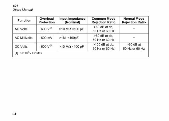
Function Overload
Protection Input Impedance
(Nominal) Common Mode Rejection Ratio
Normal Mode Rejection Ratio
AC Volts 600 V [1] >10 MΩ <100 pF >60 dB at dc,
50 Hz or 60 Hz _
AC Millivolts 600 mV >1M, <100pF >80 dB at dc,
50 Hz or 60 Hz _
DC Volts 600 V [1] >10 MΩ <100 pF >100 dB at dc, 50 Hz or 60 Hz
>60 dB at 50 Hz or 60 Hz
[1] 6 x 10⁵ V Hz Max