Embed Size (px)
DESCRIPTION
The chapter of Modulation Schemes, shortened for revision
Citation preview

Chapter 3
Digital Modulation Schemes
Wireless Information Transmission System Lab.Wireless Information Transmission System Lab.Institute of Communications EngineeringInstitute of Communications Engineeringg gg gNational Sun National Sun YatYat--sensen UniversityUniversity
1
ContentsContents
◊ 3.1 Representation of Digitally Modulated Signals
◊ 3.2 Memoryless Modulation Methods
◊ 3.3 Signaling Schemes with Memoryg g y
2
Chapter 3.1: Representation of Digitally Modulated SignalsWireless Information Transmission System Lab.Wireless Information Transmission System Lab.Institute of Communications EngineeringInstitute of Communications Engineering
Digitally Modulated Signals
g gg gNational Sun National Sun YatYat--sensen UniversityUniversity
3
3.1 Digitally Modulated Signals3.1 Digitally Modulated Signalsg y gg y g
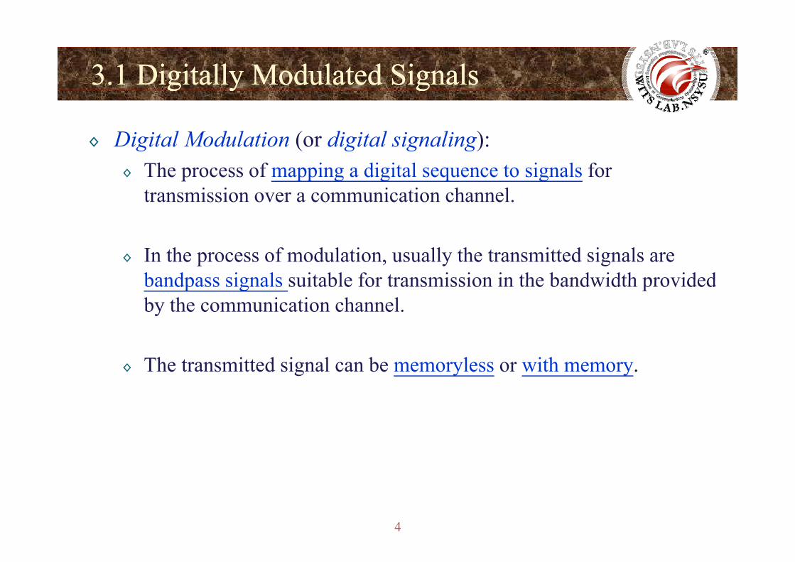
◊ Digital Modulation (or digital signaling):◊ The process of mapping a digital sequence to signals for
transmission over a communication channel.
◊ In the process of modulation, usually the transmitted signals are bandpass signals suitable for transmission in the bandwidth providedbandpass signals suitable for transmission in the bandwidth providedby the communication channel.
◊ The transmitted signal can be memoryless or with memory.
4
3.1 Digitally Modulated Signals3.1 Digitally Modulated Signalsg y gg y g
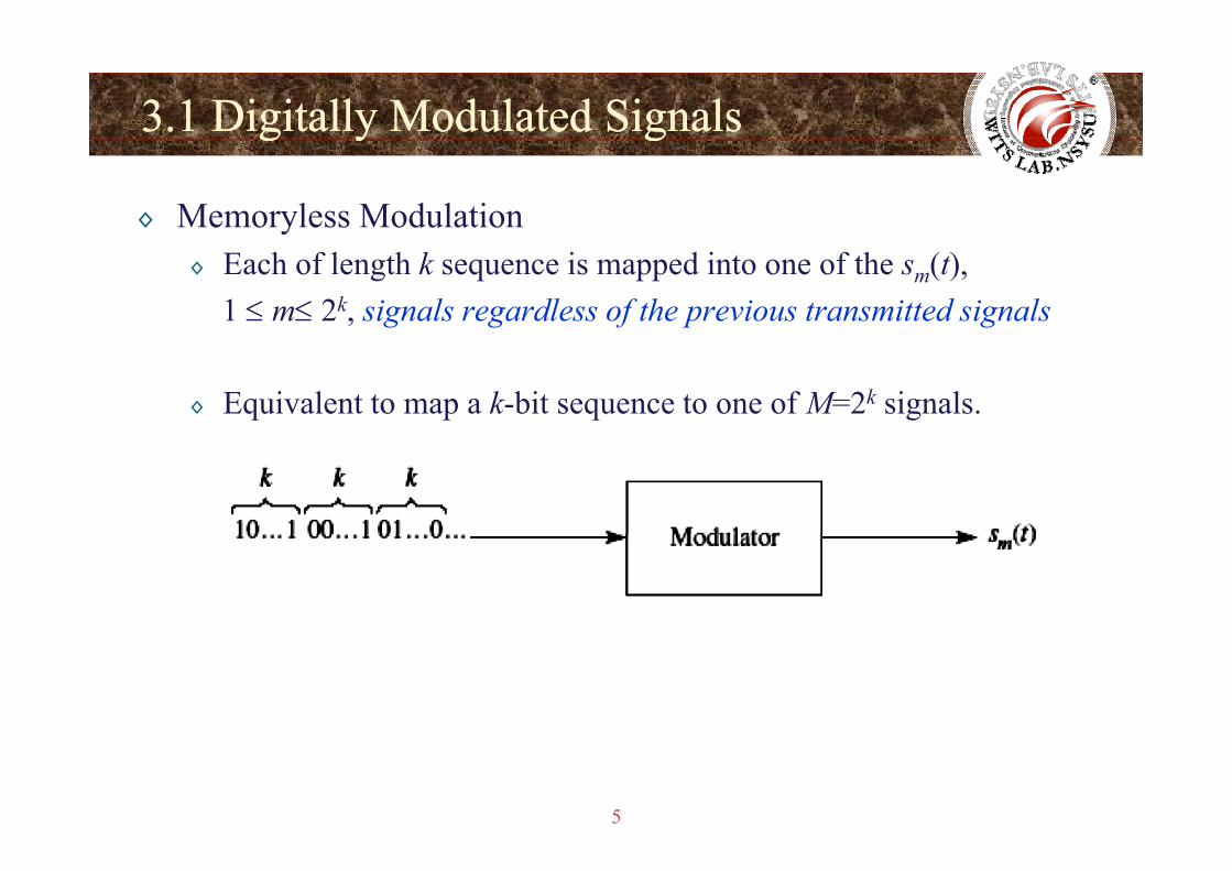
◊ Memoryless Modulation◊ Each of length k sequence is mapped into one of the sm(t),
1 ≤ m≤ 2k, signals regardless of the previous transmitted signals
◊ Equivalent to map a k-bit sequence to one of M=2k signals.
5
3.1 Digitally Modulated Signals3.1 Digitally Modulated Signalsg y gg y g
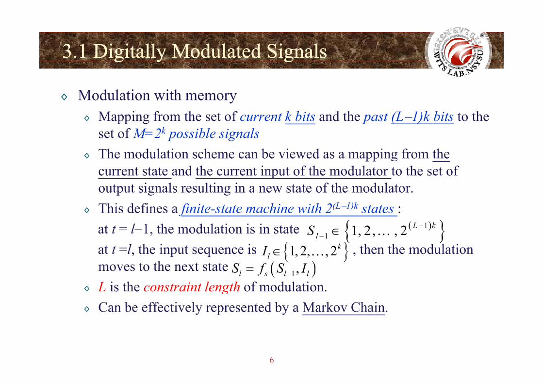
◊ Modulation with memory◊ Mapping from the set of current k bits and the past (L−1)k bits to the
set of M=2k possible signals◊ The modulation scheme can be viewed as a mapping from the
current state and the current input of the modulator to the set of output signals resulting in a new state of the modulator.output signals resulting in a new state of the modulator.
◊ This defines a finite-state machine with 2(L−1)k states : at t = l−1, the modulation is in state ( ){ }1
1 1, 2, , 2 L klS −∈ …,
at t =l, the input sequence is , then the modulation moves to the next state
{ }1 , , ,l −
( )1,l s l lS f S I−={ }1,2, , 2k
lI ∈ …
◊ L is the constraint length of modulation.◊ Can be effectively represented by a Markov Chain.
6
3.1 Digitally Modulated Signals3.1 Digitally Modulated Signalsg y gg y g
◊ Digital modulation is linear if
otherwise, it is nonlinear.1 1 2 2 1 2 1 2( ), ( ) ( ) ( )b m t b m t b b m t m t→ → ⇒ + → +
◊ Assume that the signal waveforms sm(t), 1 ≤ m ≤ M=2k
are transmitted at every seconds◊ Signal interval : sT
sT
◊ Signaling rate or Symbol rate :◊ Bit interval :
1/s sR T=
2/ / logb s sT T k T M= =◊ Bit rate : 21/ / logb s s sR T k T kR R M= = = =
7
3.1 Digitally Modulated Signals3.1 Digitally Modulated Signalsg y gg y g
◊ Let the energy of sm(t) is Em, the average signal energy is
1
M
avg m mm
E p E=
= ∑◊ pm is the probability of the m-th signal◊ If equiprobable messages, i.e. pm = 1/M, then
1
1 M
avg mE EM
= ∑◊ If Em = E, then Eavg = E 1mM =
◊ The average energy per bit when pm = 1/M is
lavg avg
bavg
E EE
k M= =
◊ The average power is 2logbavg k M
avg
bavgbavg
EP RE
T= =
8
bT

Ch 3 2 M l M d l iChapter 3.2 : Memoryless Modulation Methods
Wireless Information Transmission System Lab.Wireless Information Transmission System Lab.Institute of Communications EngineeringInstitute of Communications Engineeringg gg gNational Sun National Sun YatYat--sensen UniversityUniversity
9
3.2 Memoryless Modulation Methodsy
◊ Pulse Amplitude Modulation (PAM)◊ Phase Modulation◊ Quadrature Amplitude Modulation
◊ π/4-DQPSK◊ Dual-Carrier Modulation (DCM)
◊ Multidimensional Signaling◊ Orthogonal Signaling◊ Frequency-Shift Keying (FSK)◊ Hadamard Signals◊ Biorthogonal Signaling◊ Simplex Signaling
Si l W f f Bi C d
10
◊ Signal Waveforms from Binary Codes
3.23.2--1 Pulse Amplitude Modulation (PAM)1 Pulse Amplitude Modulation (PAM)p ( )p ( )
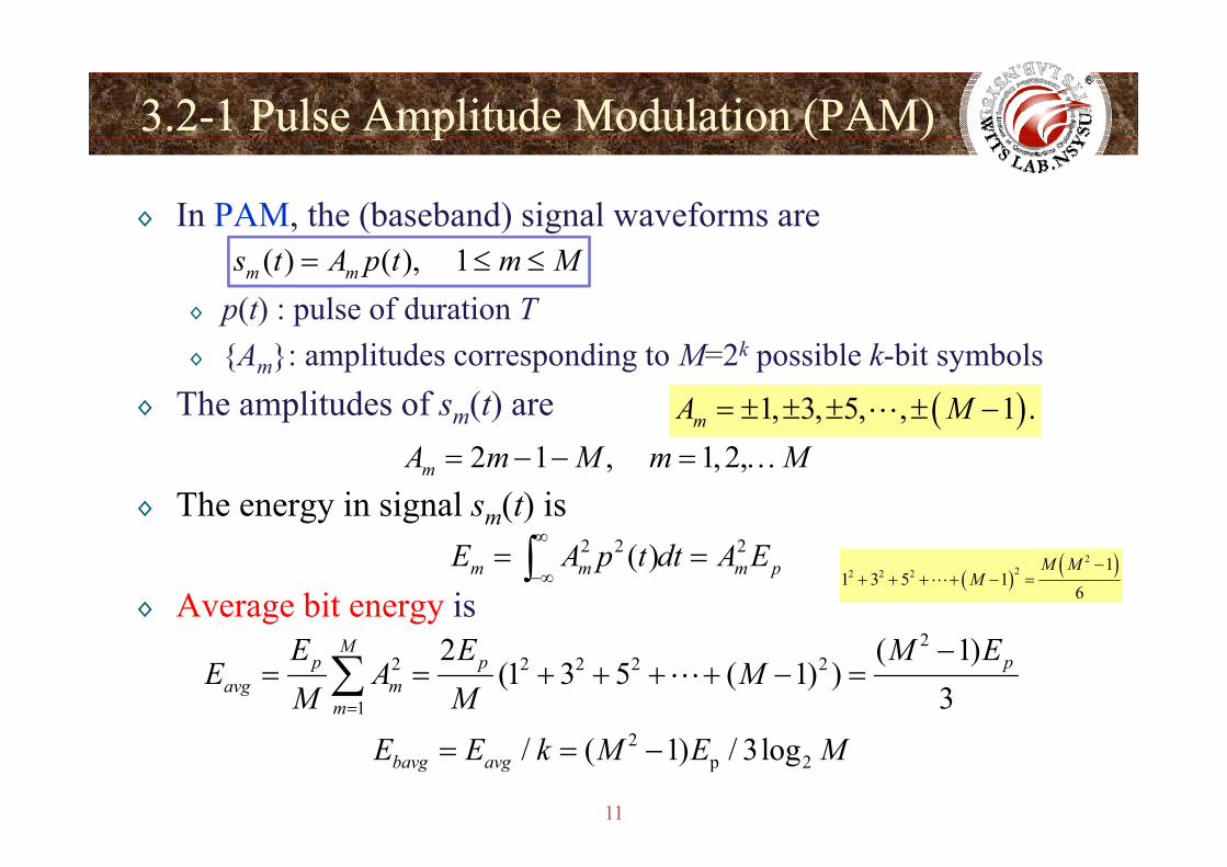
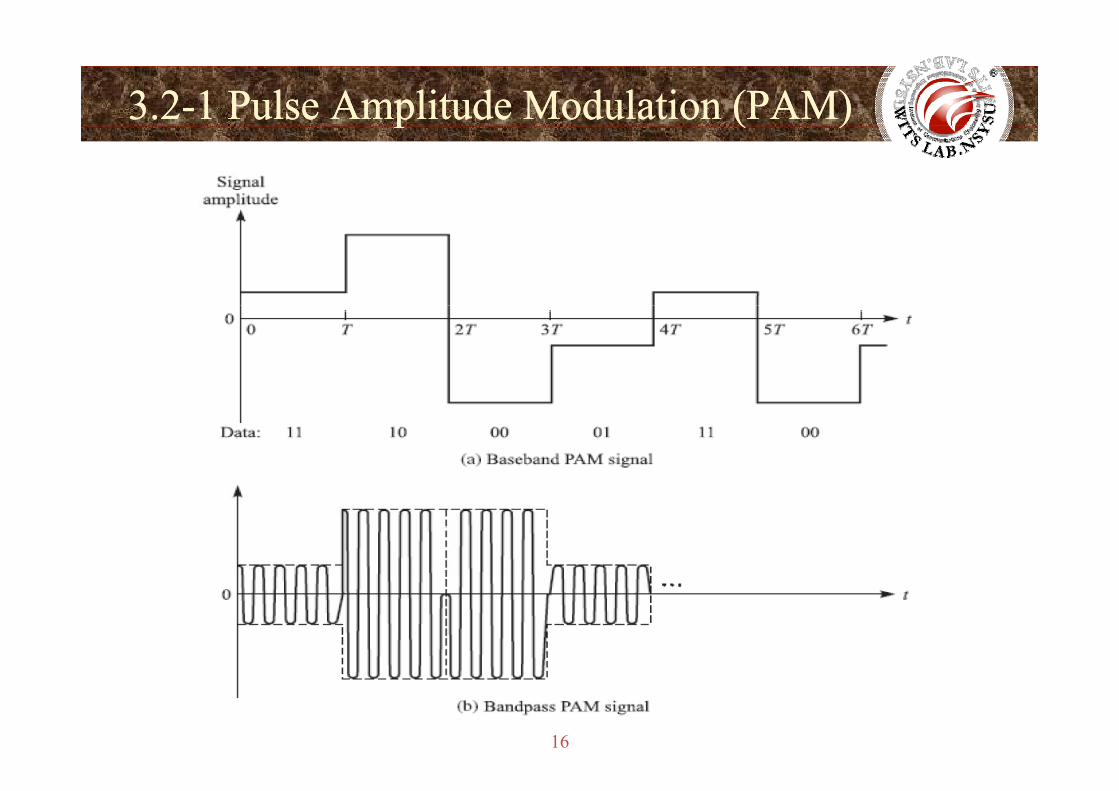
◊ In PAM, the (baseband) signal waveforms are
◊ p(t) : pulse of duration T( ) ( ), 1m ms t A p t m M= ≤ ≤
◊ {Am}: amplitudes corresponding to M=2k possible k-bit symbols ◊ The amplitudes of sm(t) are ( )1, 3, 5, , 1 .mA M= ± ± ± ± −
◊ The energy in signal sm(t) is2 1 , 1, 2,mA m M m M= − − = …
◊ Average bit energy is
2 2 2( )m m m pE A p t dt A E∞
−∞= =∫ ( ) ( )2
22 2 21
1 3 5 16
M MM
−+ + + + − =
22 2 2 2 2
1
2 ( 1)(1 3 5 ( 1) )
3
Mp p p
avg mm
E E M EE A M
M M=
−= = + + + + − =∑
11
2p 2/ ( 1) / 3logbavg avgE E k M E M= = −
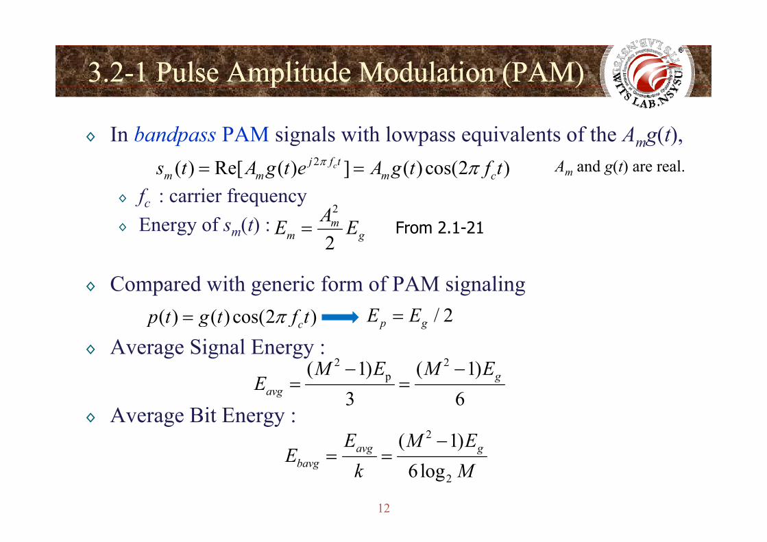
3.23.2--1 Pulse Amplitude Modulation (PAM)1 Pulse Amplitude Modulation (PAM)p ( )p ( )
◊ In bandpass PAM signals with lowpass equivalents of the Amg(t),
◊ fc : carrier frequency
2( ) Re[ ( ) ] ( ) cos(2 )cj f tm m m cs t A g t e A g t f tπ π= =
2A
Am and g(t) are real.
◊ Energy of sm(t) :2
2m
m gAE E= From 2.1-21
◊ Compared with generic form of PAM signaling( ) ( ) cos(2 )cp t g t f tπ= / 2p gE E=
◊ Average Signal Energy :2 2
p( 1) ( 1)3 6
gavg
M E M EE
− −= =
◊ Average Bit Energy :3 6avg
2( 1)avg gE M EE
−= =
12
26 logbavgEk M
= =
3.23.2--1 Pulse Amplitude Modulation (PAM)1 Pulse Amplitude Modulation (PAM)p ( )p ( )
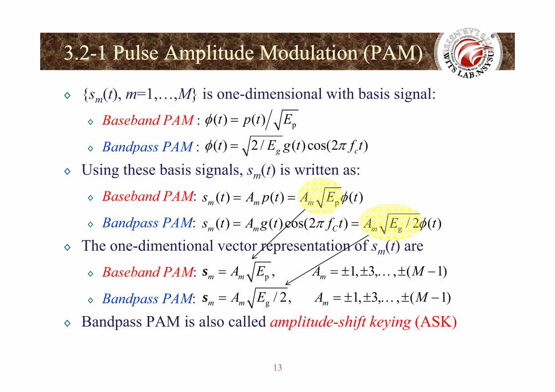
◊ {sm(t), m=1,…,M} is one-dimensional with basis signal:
◊ Baseband PAM :
◊ Bandpass PAM :
p( ) ( )t p t Eφ =
( ) 2 / ( )cos(2 )g ct E g t f tφ π=◊ p◊ Using these basis signals, sm(t) is written as:
◊ Baseband PAM:
( ) ( ) ( )g cg fφ
( ) ( ) ( )s t A p t A E tφ◊ Baseband PAM:
◊ Bandpass PAM:Th di i l i f ( )
p( ) ( ) ( )m m ms t A p t A E tφ= =
g( ) ( ) cos(2 ) / 2 ( )m m C ms t A g t f t A E tπ φ= =
◊ The one-dimentional vector representation of sm(t) are
◊ Baseband PAM: p , 1, 3, , ( 1)m m mA E A M= = ± ± … ± −s
◊ Bandpass PAM:◊ Bandpass PAM is also called amplitude-shift keying (ASK)
g / 2, 1, 3, , ( 1)m m mA E A M= = ± ± … ± −s
13
p p f y g ( )
3.23.2--1 Pulse Amplitude Modulation (PAM)1 Pulse Amplitude Modulation (PAM)p ( )p ( )
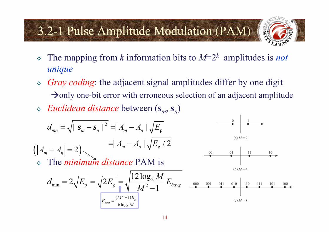
◊ The mapping from k information bits to M=2k amplitudes is not unique
◊ Gray coding: the adjacent signal amplitudes differ by one digit only one-bit error with erroneous selection of an adjacent amplitude
◊ Euclidean distance between (sm, sn)2
p|| || | |
| | / 2
mn m n m nd A A E
A A E
= − = −s s
◊ The minimum distance PAM is
g | | / 2m nA A E= −( )2m nA A− =
2min p g 2
12log2 21 bavgMd E E E
M= = =
−2
14
2
2
( 1)6 log
gbavg
M EE
M−
=
3.23.2--1 Pulse Amplitude Modulation (PAM)1 Pulse Amplitude Modulation (PAM)p ( )p ( )
◊ The following bandpass signal is double-sideband (DSB)
◊ Requires twice the channel bandwidth
2( ) Re[ ( ) ] ( ) cos(2 )cj f tm m m cs t A g t e A g t f tπ π= =
◊ We may use single-sideband (SSB) PAM:
◊ is the Hilbert transform of
2ˆ( ) Re[ ( ( ) ( )) ]cj f tm ms t A g t jg t e π= ±
ˆ ( )g t ( )g t◊ Bandwidth is half of DSB
◊ When M = 2, s1(t) = -s2(t)◊ E1= E2 =1◊ Cross-correlation coefficient = -1
15
◊ Binary antipodal signaling
3.23.2--1 Pulse Amplitude Modulation (PAM)1 Pulse Amplitude Modulation (PAM)p ( )p ( )
16
3.23.2--2 Phase Modulation2 Phase Modulation
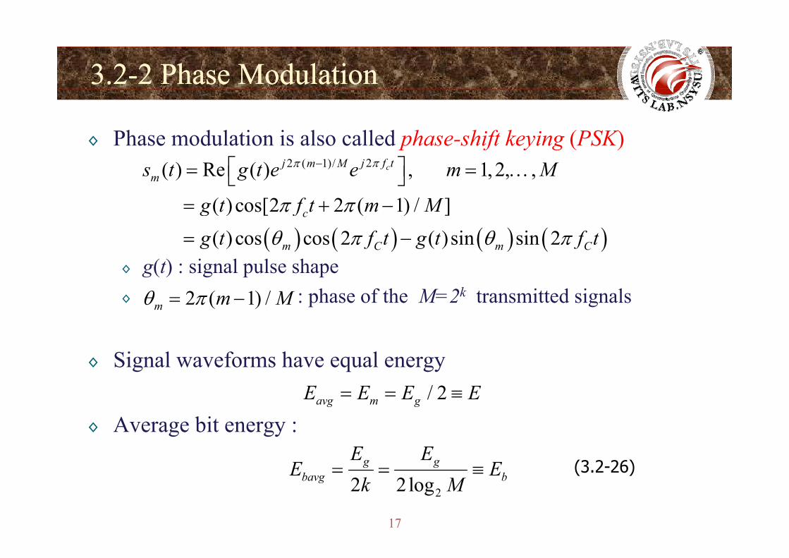
◊ Phase modulation is also called phase-shift keying (PSK)22 ( 1)/( ) Re ( ) , 1, 2, ,
( ) cos[2 2 ( 1) / ]
cj f tj m Mm
c
s t g t e e m M
g t f t m M
ππ
π π
−⎡ ⎤= = …⎣ ⎦= + −
◊ g(t) : signal pulse shape( ) ( ) ( ) ( )
( ) ( ) ( ) cos cos 2 ( )sin sin 2
c
m C m C
g fg t f t g t f tθ π θ π= −
◊ : phase of the M=2k transmitted signals2 ( 1) /m m Mθ π= −
◊ Signal waveforms have equal energy/ 2avg m gE E E E= = ≡
◊ Average bit energy : g g
g gE EE E= = ≡ (3 2-26)
17
22 2logbavg bE Ek M
= = ≡ (3.2 26)
3.23.2--2 Phase Modulation2 Phase Modulation
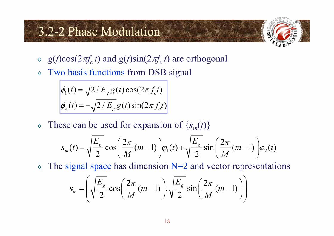
◊ g(t)cos(2πfc t) and g(t)sin(2πfc t) are orthogonal◊ Two basis functions from DSB signal
1( ) 2 / ( ) cos(2 )t E g t f tφ π=1( ) 2 / ( ) cos(2 )g ct E g t f tφ π
2 ( ) 2 / ( )sin(2 )g ct E g t f tφ π= −
◊ These can be used for expansion of {sm(t)}
2 2( ) ( 1) ( ) i ( 1) ( )g gE Eπ π⎛ ⎞ ⎛ ⎞⎜ ⎟ ⎜ ⎟
◊ The signal space has dimension N=2 and vector representations
1 2( ) cos ( 1) ( ) sin ( 1) ( )2 2
g gms t m t m t
M Mπ πϕ ϕ⎛ ⎞ ⎛ ⎞= − + −⎜ ⎟ ⎜ ⎟
⎝ ⎠ ⎝ ⎠
2 2cos ( 1) , sin ( 1)2 2
g gm
E Em m
M Mπ π⎛ ⎞⎛ ⎞ ⎛ ⎞= − −⎜ ⎟⎜ ⎟ ⎜ ⎟⎜ ⎟⎝ ⎠ ⎝ ⎠⎝ ⎠
s
18
⎝ ⎠ ⎝ ⎠⎝ ⎠

3.23.2--2 Phase Modulation2 Phase Modulation
◊ M=2, BPSK M=4, QPSK M=8, 8-PSK
◊ BPSK=Binary PAMy◊ The mapping is not unique and Gray coding is preferred◊ A variant of four-phase PSK (QPSK), called π/4-QPSK, is
19
◊ A variant of four phase PSK (QPSK), called π/4 QPSK, is obtained by introducing an additional π/4 phase shift.
3.23.2--2 Phase Modulation2 Phase Modulation
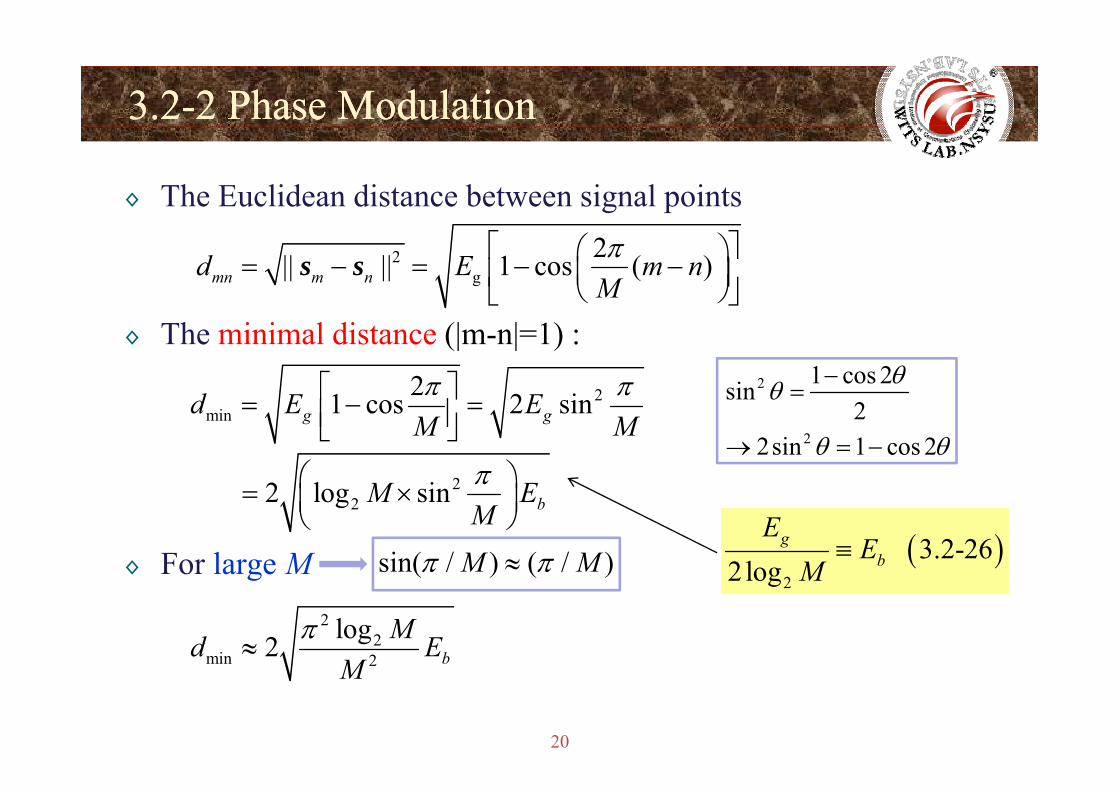
◊ The Euclidean distance between signal points
2g
2|| || 1 cos ( )mn m nd E m nMπ⎡ ⎤⎛ ⎞= − = − −⎜ ⎟⎢ ⎥⎝ ⎠⎣ ⎦
s s
◊ The minimal distance (|m-n|=1) :
221 2 id E Eπ π⎡ ⎤ 2 1 cos 2sin θθ −=2
min 1 cos 2 sing gd E EM M
⎡ ⎤= − =⎢ ⎥⎣ ⎦
22 l iM Eπ⎛ ⎞⎜ ⎟
2
sin2
2sin 1 cos 2
θ
θ θ
=
→ = −
◊ For large M
222 log sin bM E
M⎛ ⎞= ×⎜ ⎟⎝ ⎠
sin( / ) ( / )M Mπ π≈ ( ) 3.2-262log
gb
EE
M≡g ( ) ( )
22
min 2
log2 bMd E
Mπ
≈
22 log M
20
2M
3.23.2--3 3 QuadratureQuadrature Amplitude ModulationAmplitude ModulationQQ pp
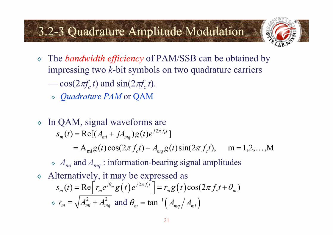
◊ The bandwidth efficiency of PAM/SSB can be obtained by impressing two k-bit symbols on two quadrature carriers⎯ cos(2πfc t) and sin(2πfc t).◊ Quadrature PAM or QAM
◊ In QAM, signal waveforms are2( ) Re[( ) ( ) ]cj f t
m mi mqs t A jA g t e π= +
◊ Ami and Amq : information-bearing signal amplitudesmi A ( )cos(2 ) ( )sin(2 ), m 1,2, ,Mc mq cg t f t A g t f tπ π= − = …
◊ Alternatively, it may be expressed as( ) ( )2( ) Re cos(2 )m cj j f t
m m m c ms t r e g t e r g t f tθ π π θ⎡ ⎤= = +⎣ ⎦2 2 ( )
21
◊ and 2 2m mi mqr A A= + ( )1tanm mq miA Aθ −=
3.23.2--3 3 QuadratureQuadrature Amplitude ModulationAmplitude ModulationQQ pp
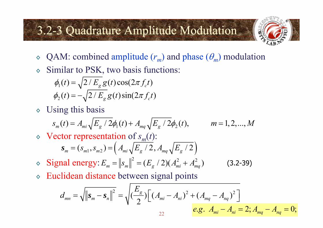
◊ QAM: combined amplitude (rm) and phase (θm) modulation◊ Similar to PSK, two basis functions:
1( ) 2 / ( ) cos(2 )g ct E g t f tφ π=
◊ Using this basis2 ( ) 2 / ( )sin(2 )g ct E g t f tφ π= −
g
◊ Vector representation of sm(t):1 2( ) / 2 ( ) / 2 ( ), 1, 2,...,m mi g mq gs t A E t A E t m Mφ φ= + =
p m( )
◊ Signal energy:( )1 2( , ) / 2, / 2m m m mi g mq gs s A E A E= =s
2 2 2( / 2)( )m m g mi mqE s E A A= = + (3.2-39)g gy◊ Euclidean distance between signal points
( )( )m m g mi mq
2 2 2gE⎡ ⎤
( )
22
2 2 2( ) ( ) ( )2
gmn m n mi ni mq nqd A A A A⎡ ⎤= − = − + −⎣ ⎦s s
. . 2; 0;mi ni mq nqe g A A A A− = − =
3.23.2--3 3 QuadratureQuadrature Amplitude ModulationAmplitude ModulationQQ pp
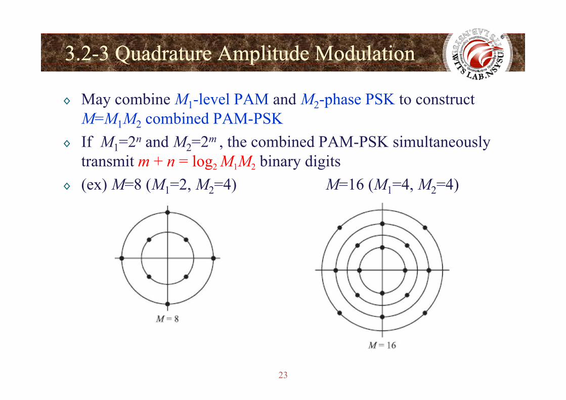
◊ May combine M1-level PAM and M2-phase PSK to construct M=M1M2 combined PAM-PSK
◊ If M1=2n and M2=2m , the combined PAM-PSK simultaneouslytransmit m + n = log2 M1M2 binary digits
◊ (ex) M=8 (M1=2, M2=4) M=16 (M1=4, M2=4)
23
3.23.2--3 3 QuadratureQuadrature Amplitude ModulationAmplitude ModulationQQ pp
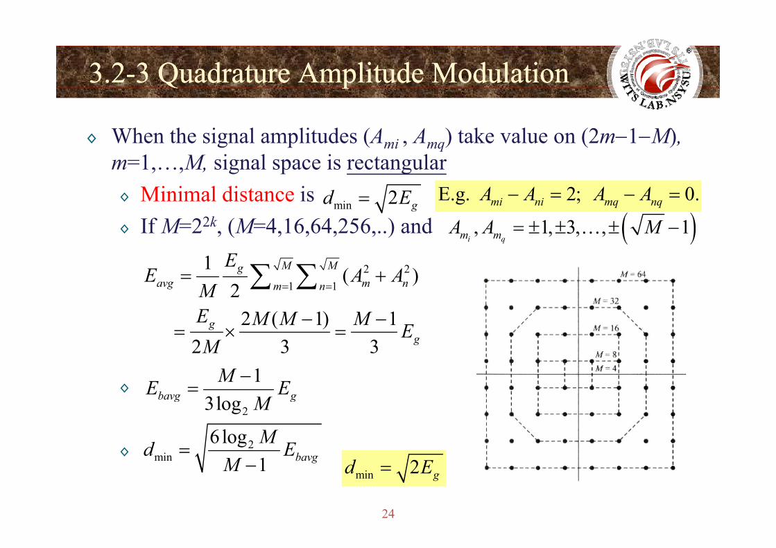
◊ When the signal amplitudes (Ami , Amq) take value on (2m−1−M), qm=1,…,M, signal space is rectangular◊ Minimal distance is
min 2 gd E= E.g. 2; 0.mi ni mq nqA A A A− = − =
◊ If M=22k, (M=4,16,64,256,..) and ( ), 1, 3, , 1i qm mA A M= ± ± ± −…
2 21 ( )M MgEE A A+∑ ∑1 1
( )2
2 ( 1) 1
gavg m nm n
g
E A AME M M M E
= == +
− −= × =
∑ ∑
◊
2 3 3 gE
M×
13lbavg g
ME EM
−=
◊
23logbavg gM
2min
6 log1 bavgMd E
M=
2d E
24
min 1 bavgM − min 2 gd E=
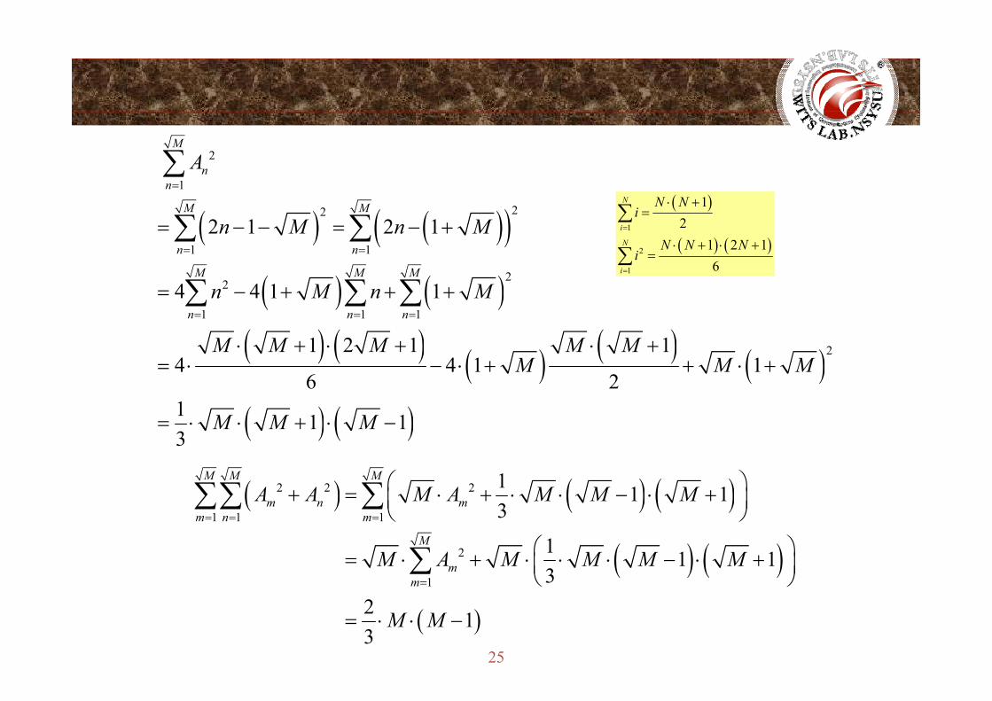
2
1
M
nn
A=
∑
( ) ( )( )22
1 12 1 2 1
M M
n n
M M M
n M n M= =
= − − = − +∑ ∑( )
( ) ( )1
2
1
12
1 2 16
N
i
N
i
N Ni
N N Ni
=
=
⋅ +=
⋅ + ⋅ +=
∑
∑
( ) ( )( ) ( ) ( ) ( ) ( )
22
1 1 1
2
4 4 1 1
1 2 1 1
M M M
n n nn M n M
M M M M M= = =
= − + + +
⋅ + ⋅ + ⋅ +
∑ ∑ ∑1i=
( ) ( ) ( ) ( ) ( )( ) ( )
21 2 1 14 4 1 1
6 21 1 1
M M M M MM M M
M M M
+ + += ⋅ − ⋅ + + ⋅ +
= ⋅ ⋅ + ⋅ −( ) ( )3
( ) ( ) ( )2 2 2 1 1 13
M M M
m n mA A M A M M M⎛ ⎞+ = ⋅ + ⋅ ⋅ − ⋅ +⎜ ⎟⎝ ⎠
∑∑ ∑( ) ( ) ( )
( ) ( )1 1 1
2
1
3
1 1 13
m n m
M
mm
M A M M M M
= = =
=
⎝ ⎠
⎛ ⎞= ⋅ + ⋅ ⋅ ⋅ − ⋅ +⎜ ⎟⎝ ⎠
∑
25
( )2 13
M M= ⋅ ⋅ −
3.23.2--3 3 QuadratureQuadrature Amplitude ModulationAmplitude ModulationQQ pp
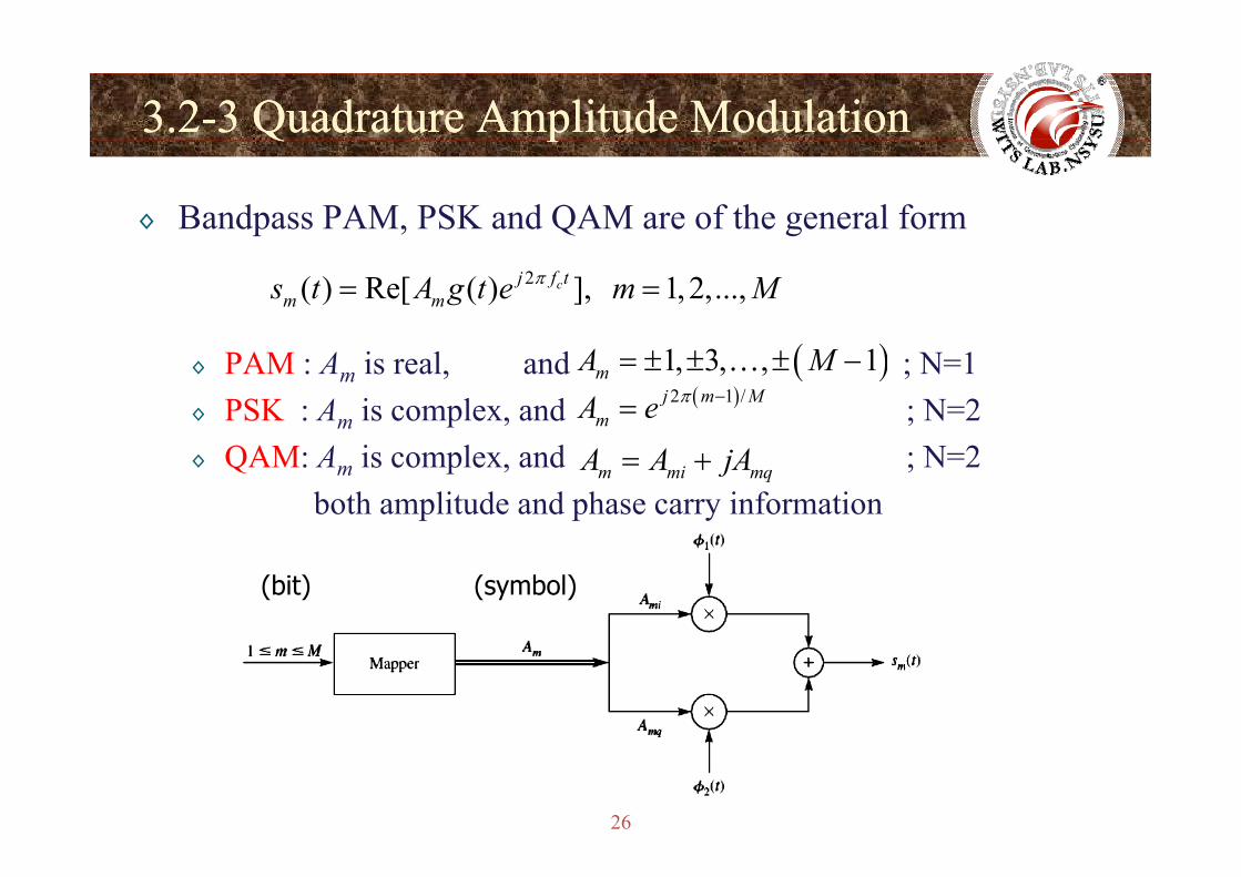
◊ Bandpass PAM, PSK and QAM are of the general form2( ) Re[ ( ) ], 1, 2,...,cj f t
m ms t A g t e m Mπ= =
◊ PAM : Am is real, and ; N=1◊ PSK : Am is complex, and ; N=2( )2 1 /j m M
mA e π −=( )1, 3, , 1mA M= ± ± ± −…
◊ QAM: Am is complex, and ; N=2both amplitude and phase carry information
m mi mqA A jA= +
(bit) (symbol)
26
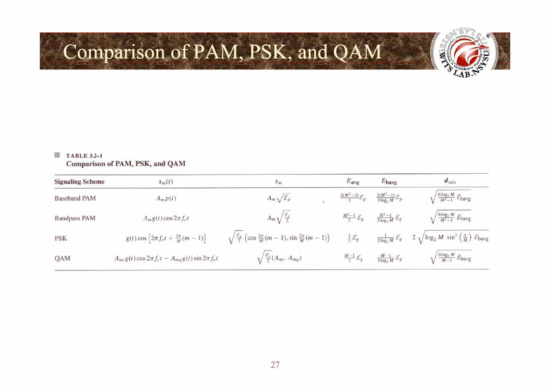
Comparison of PAM, PSK, and QAMComparison of PAM, PSK, and QAMp Qp Q
27
MemorylessMemoryless Modulation MethodsModulation Methods
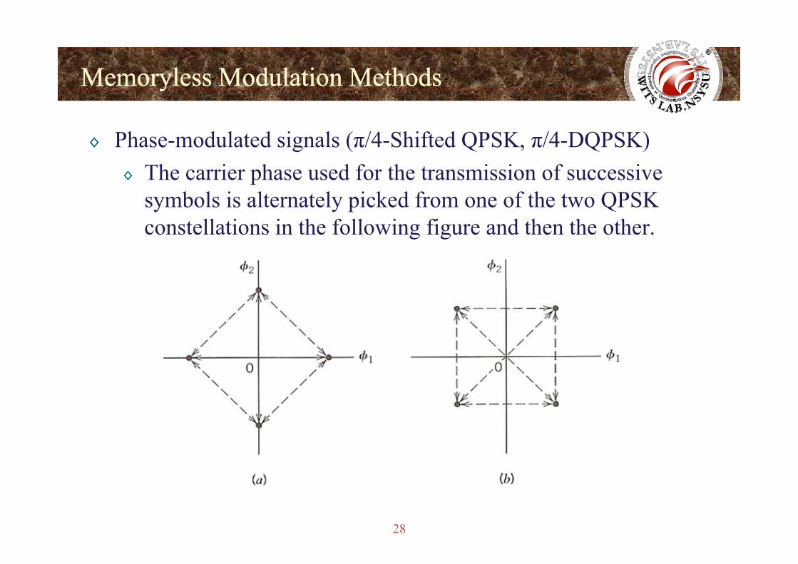
◊ Phase-modulated signals (π/4-Shifted QPSK, π/4-DQPSK)
yy
◊ The carrier phase used for the transmission of successive symbols is alternately picked from one of the two QPSK constellations in the following figure and then the other.
28
MemorylessMemoryless Modulation MethodsModulation Methods
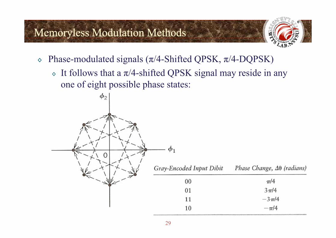
◊ Phase-modulated signals (π/4-Shifted QPSK, π/4-DQPSK)
yy
◊ It follows that a π/4-shifted QPSK signal may reside in any one of eight possible phase states:
29
MemorylessMemoryless Modulation MethodsModulation Methods
◊ Phase-modulated signals (π/4-Shifted QPSK, π/4-DQPSK)
yy
◊ Attractive features of the π/4-shifted QPSK scheme◊ The phase transitions from one symbol to the next are
restricted to ±π/4 and ±3π/4.◊ Envelope variations due to filtering are significantly
reduced.◊ π/4-shifted QPSK signals can be noncoherently detected,
h b id bl i lif i h i d ithereby considerably simplifying the receiver design.◊ Like QPSK signals, π/4-shifted QPSK can be differently
encoded in which case we should really speak of π/4encoded, in which case we should really speak of π/4-shifted DQPSK .
◊ π/4 DQPSK is adopted in IS 54/136
30
◊ π/4-DQPSK is adopted in IS-54/136.
MemorylessMemoryless Modulation MethodsModulation Methods
◊ Dual-Carrier Modulation (DCM)
yy
◊ Multi-band OFDM (IEEE 802.15.3 a Ultra Wideband)◊ The coded and interleaved binary serial input data, b[i] where
i = 0, 1, 2, …, shall be divided into groups of 200 bits and converted into 100 complex numbers using a technique called d l i d l tidual-carrier modulation.
◊ The conversion shall be performed as follows:1 Th 200 d d bi d i 50 f 4 bi1.The 200 coded bits are grouped into 50 groups of 4 bits.
Each group is represented as (b[g(k)], b[g(k)+1], b[g(k) + 50)] b[g(k) + 51]) where k [0 49] and50)], b[g(k) + 51]), where k [0, 49] and
( ) [ ][ ]
0, 24225 492 50
kkg k
kk⎧ ∈⎪= ⎨⎪⎩
31
( ) [ ]25, 492 50 kk⎨ ∈+⎪⎩
MemorylessMemoryless Modulation MethodsModulation Methods
◊ Dual-Carrier Modulation (DCM)
yy
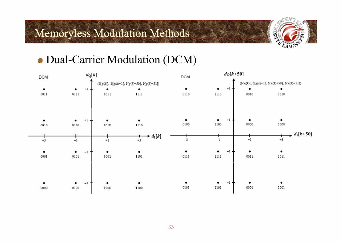
2. Each group of 4 bits (b[g(k)], b[g(k)+1], b[g(k) + 50)], b[g(k) + 51]) shall be mapped onto a four-dimensional constellation, and converted into two complex numbers (d[k], d[k + 50]). p ( [ ], [ ])
3. The complex numbers shall be normalized using a normalization factor KMOD.
◊ The normalization factor KMOD = 10-1/2 is used for the dual-carrier modulationcarrier modulation.
◊ An approximate value of the normalization factor may be used, as long as the device conforms to the modulation accuracy requirements.
32
MemorylessMemoryless Modulation MethodsModulation Methods
Dual-Carrier Modulation (DCM)
yy
33
MemorylessMemoryless Modulation MethodsModulation Methods
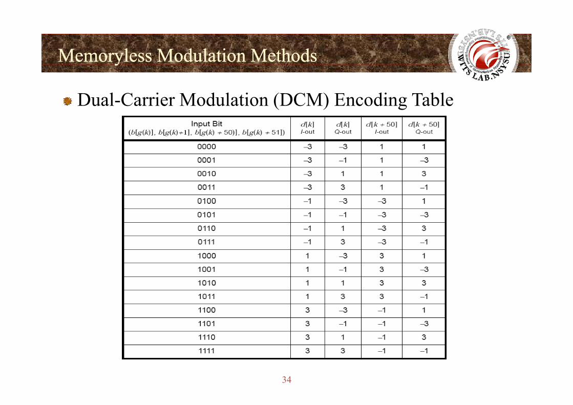
Dual-Carrier Modulation (DCM) Encoding Table
yy
34
3.23.2--4 Multidimensional Signaling4 Multidimensional Signalingg gg g
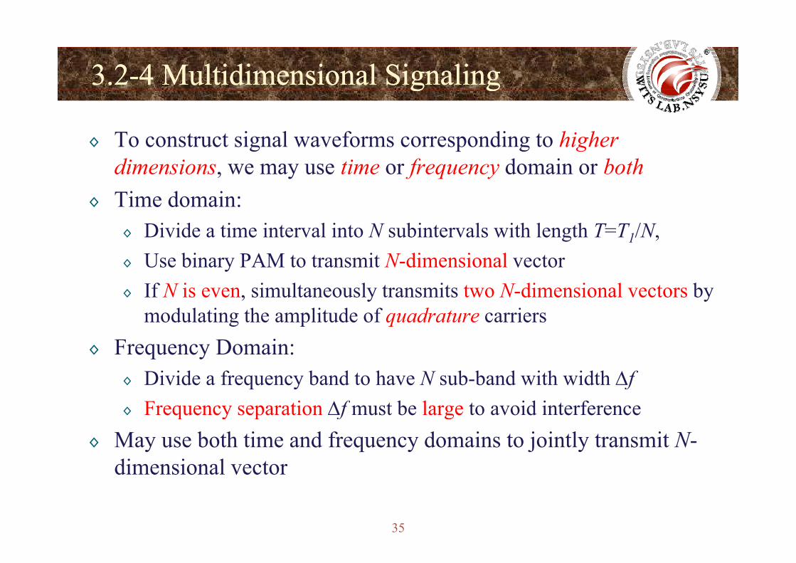
◊ To construct signal waveforms corresponding to higher dimensions, we may use time or frequency domain or both
◊ Time domain: ◊ Divide a time interval into N subintervals with length T=T1/N,◊ Use binary PAM to transmit N-dimensional vector◊ If N is even, simultaneously transmits two N-dimensional vectors by
modulating the amplitude of quadrature carriers◊ Frequency Domain:◊ Frequency Domain:
◊ Divide a frequency band to have N sub-band with width Δf◊ Frequency separation Δf must be large to avoid interference◊ Frequency separation Δf must be large to avoid interference
◊ May use both time and frequency domains to jointly transmit N-dimensional vector
35
dimensional vector
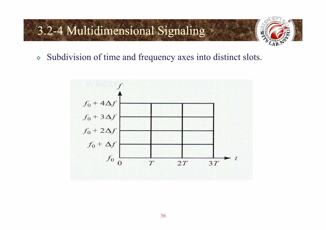
3.23.2--4 Multidimensional Signaling4 Multidimensional Signalingg gg g
◊ Subdivision of time and frequency axes into distinct slots.
36
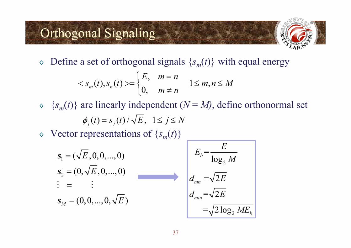
Orthogonal SignalingOrthogonal Signalingg g gg g g
◊ Define a set of orthogonal signals {sm(t)} with equal energy,
( ), ( ) 1 ,0, m n
E m ns t s t m n M
m n=⎧
< >= ≤ ≤⎨ ≠⎩◊ {sm(t)} are linearly independent (N = M), define orthonormal set
( ) ( ) / , 1j jt s t E j Nφ = ≤ ≤
◊ Vector representations of {sm(t)}( ) ( ) ,j j jφ
( ) = EE1
2
( ,0,0,...,0)
(0, ,0,...,0)
E
E
=
=
s
s2
=logbE
M
= 2d E
(0,0,...,0, )M E
=
=s
2
= 2
2log
mn
min
d E
d E
ME
37
2 = 2log bME
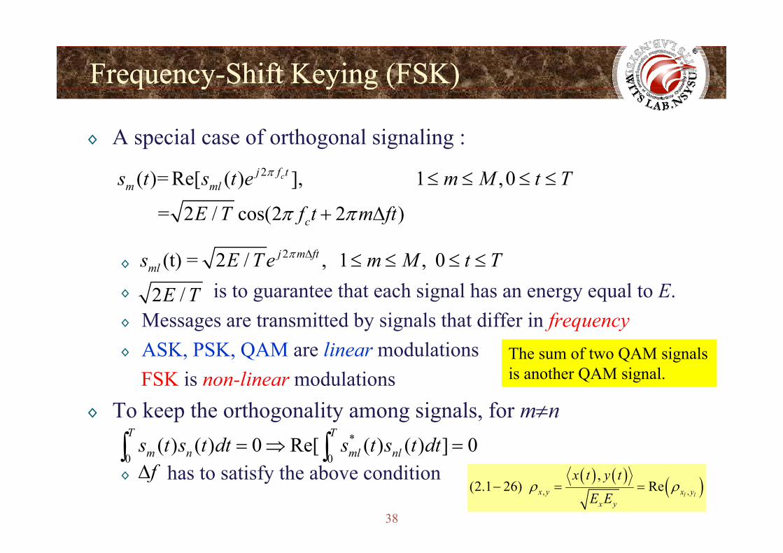
FrequencyFrequency--Shift Keying (FSK)Shift Keying (FSK)q yq y y g ( )y g ( )
◊ A special case of orthogonal signaling :2( )= Re[ ( ) ], 1 ,0
= 2 / cos(2 2 )
cj f tm mls t s t e m M t T
E T f t m ft
π
π π
≤ ≤ ≤ ≤
+ Δ
◊
= 2 / cos(2 2 )cE T f t m ftπ π+ Δ
2 (t) = 2 / , 1 , 0j m ft
mls E T e m M t Tπ Δ ≤ ≤ ≤ ≤◊ is to guarantee that each signal has an energy equal to E.◊ Messages are transmitted by signals that differ in frequency
2 /E T
◊ ASK, PSK, QAM are linear modulationsFSK is non-linear modulationsk h h li i l f
The sum of two QAM signalsis another QAM signal.
◊ To keep the orthogonality among signals, for m≠n*
0 0( ) ( ) 0 Re[ ( ) ( ) ] 0
T T
m n ml nls t s t dt s t s t dt= ⇒ =∫ ∫fΔ
38
◊ has to satisfy the above conditionfΔ ( ) ( ) ( ), ,
,(2.1 26) Re
l lx y x yx y
x t y t
E Eρ ρ− = =
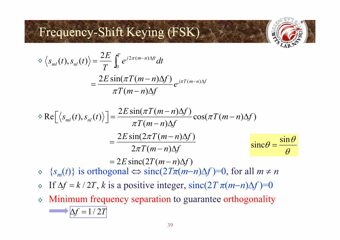
FrequencyFrequency--Shift Keying (FSK)Shift Keying (FSK)q yq y y g ( )y g ( )
◊ 2 ( )
0
2( ), ( )T j m n ft
ml nlEs t s t e dt
Tπ − Δ= ∫0
( )2 sin( ( ) ) ( )
ml nl
j T m n f
TE T m n f e
T m n fππ
π− Δ− Δ
=− Δ
∫
◊
( )T m n fπ Δ
2 sin( ( ) )Re ( ), ( ) cos( ( ) )( )ml nl
E T m n fs t s t T m n ff
π π− Δ⎡ ⎤ = − Δ⎣ ⎦( ), ( ) ( ( ) )
( )2 sin(2 ( ) )
2 ( )
ml nl fT m n f
E T m n fT f
ππ
⎣ ⎦ − Δ− Δ
=Δ
sinsinc θθ =
◊ {sm(t)} is orthogonal ⇔ sinc(2Tπ(m−n)Δf )=0, for all m ≠ n
2 ( ) 2 sinc(2 ( ) )
T m n fE T m n f
π − Δ= − Δ
sincθθ
{ m( )} g ( ( ) f ) ,◊ If , k is a positive integer, sinc(2T π(m−n)Δf )=0◊ Minimum frequency separation to guarantee orthogonality
/ 2f k TΔ =
39
◊ Minimum frequency separation to guarantee orthogonality1/ 2f TΔ =
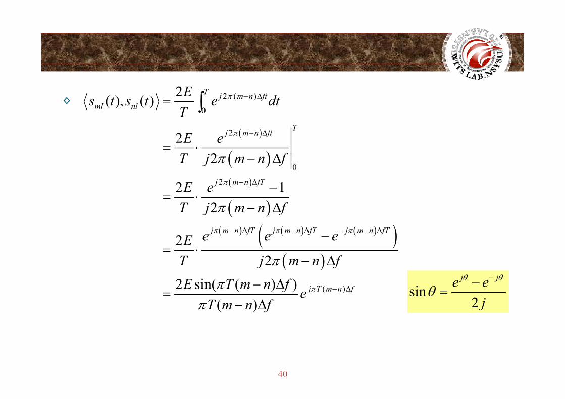
◊ 2 ( )
0
2( ), ( )T j m n ft
ml nlEs t s t e dt
Tπ − Δ= ∫
( )
( )
0
222
ml nl
Tj m n ft
T
E eT j f
π − Δ
= ⋅Δ
∫
( )( )
0
2
2
2 1j m n fT
T j m n f
E e π
π− Δ
− Δ
−= ⋅
( )( ) ( ) ( )( )
2
2j m n fT j m n fT j m n fT
T j m n f
e e eEπ π π
π− Δ − Δ − − Δ
− Δ
−( )( )
( )
22 sin( ( ) ) j T m n f
T j m n fE T m n f π
π
π − Δ
= ⋅− Δ
− Δ sinj je eθ θ
θ−−( )( ( ) )
( )j T m n ff e
T m n fπ
πΔ=
− Δsin
2 jθ =
40
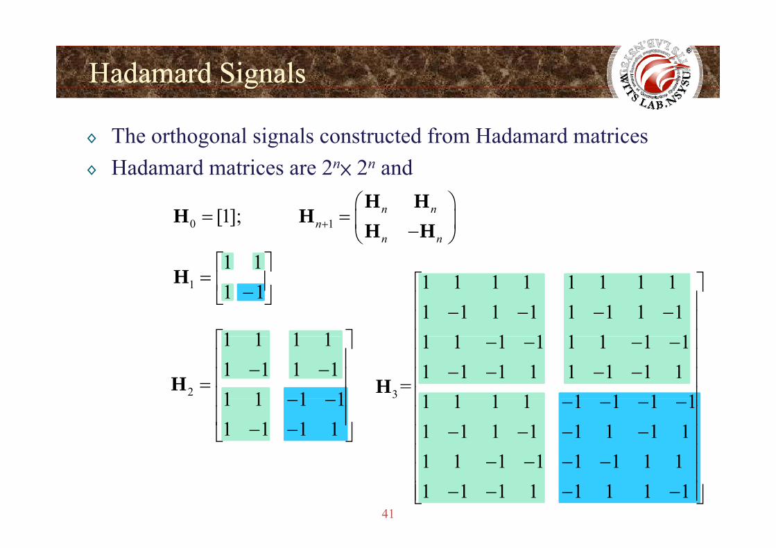
HadamardHadamard SignalsSignalsgg
◊ The orthogonal signals constructed from Hadamard matrices◊ Hadamard matrices are 2n× 2n and
[1] n n⎛ ⎞⎜ ⎟
H HH H0 1[1]; n n
nn n
+= = ⎜ ⎟−⎝ ⎠H H
H H1 1⎡ ⎤
⎢ ⎥H ⎡ ⎤1 1 1= ⎢ ⎥−⎣ ⎦
H
1 1 1 1⎡ ⎤
1 1 1 1 1 1 1 11 1 1 1 1 1 1 11 1 1 1 1 1 1 1
⎡ ⎤⎢ ⎥− − − −⎢ ⎥⎢ ⎥
2
1 1 1 11 1 1 11 1 1 1
⎡ ⎤⎢ ⎥− −⎢ ⎥=⎢ ⎥
H 3
1 1 1 1 1 1 1 11 1 1 1 1 1 1 1
=1 1 1 1 1 1 1 1
⎢ ⎥− − − −⎢ ⎥− − − −⎢ ⎥⎢ ⎥H1 1 1 1
1 1 1 1⎢ ⎥− −⎢ ⎥− −⎣ ⎦
1 1 1 1 1 1 1 11 1 1 1 1 1 1 11 1 1 1 1 1 1 1
⎢ ⎥− − − −⎢ ⎥
− − − −⎢ ⎥⎢ ⎥
41
1 1 1 1 1 1 1 11 1 1 1 1 1 1 1
⎢ ⎥− − − −⎢ ⎥
− − − −⎢ ⎥⎣ ⎦
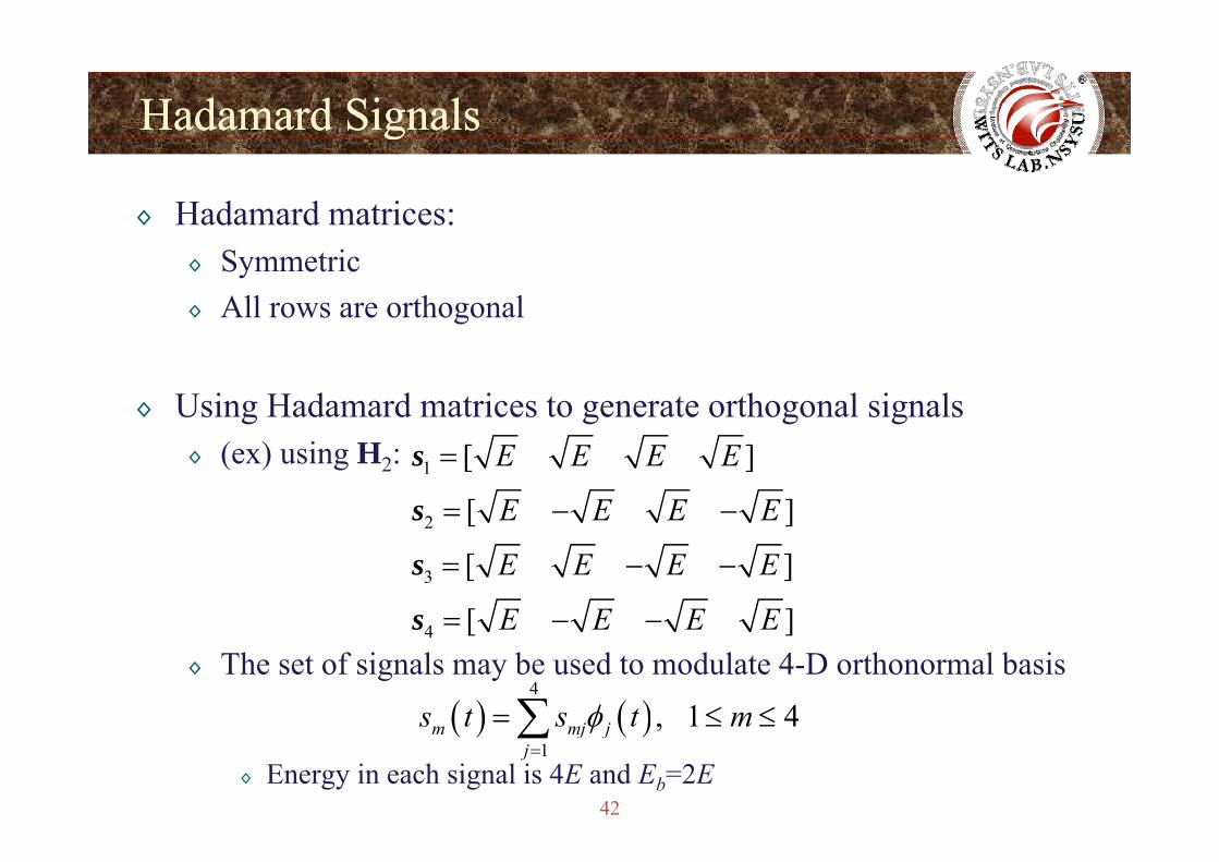
HadamardHadamard SignalsSignalsgg
◊ Hadamard matrices:◊ Symmetric◊ All rows are orthogonal
◊ Using Hadamard matrices to generate orthogonal signals◊ (ex) using H2: 1
2
[ ]
[ ]
E E E E
E E E E
=
= − −
s
s
3
4
[ ]
[ ]
E E E E
E E E E
= − −
= − −
s
s◊ The set of signals may be used to modulate 4-D orthonormal basis
4 [ ]E E E Es
( ) ( )4
, 1 4j js t s t mφ= ≤ ≤∑
42◊ Energy in each signal is 4E and Eb=2E
( ) ( )1
, 1 4m mj jj
s t s t mφ=
≤ ≤∑
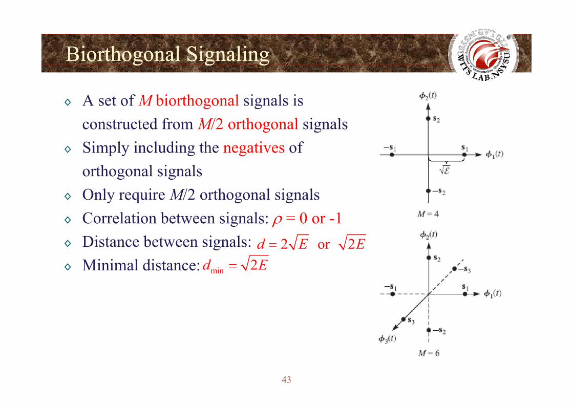
BiorthogonalBiorthogonal SignalingSignalinggg g gg g
◊ A set of M biorthogonal signals is constructed from M/2 orthogonal signals
◊ Simply including the negatives of orthogonal signals
◊ Only require M/2 orthogonal signalsy q g g◊ Correlation between signals: ρ = 0 or -1◊ Distance between signals: 2 or 2d E E=g◊ Minimal distance:
2 or 2d E E
min 2d E=
43
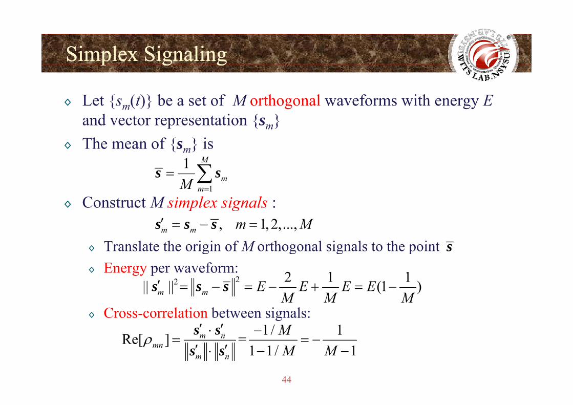
Simplex SignalingSimplex Signalingp g gp g g
◊ Let {sm(t)} be a set of M orthogonal waveforms with energy Eand vector representation {sm}
◊ The mean of {sm} is
◊ Construct M simplex signals :1
1 M
mmM =
= ∑s s
◊ Construct M simplex signals :
◊ Translate the origin of M orthogonal signals to the point, 1, 2,...,m m m M′ = − =s s s
s◊ Translate the origin of M orthogonal signals to the point◊ Energy per waveform:
22 2 1 1|| || (1 )m m E E E EM M M
′ = − = − + = −s s s
s
◊ Cross-correlation between signals:m m M M M
1/ 1Re[ ] =m n Mρ′ ′⋅ −
= = −s s
44
Re[ ] =1 1/ 1mn
m n M Mρ = = −
′ ′⋅ − −s s
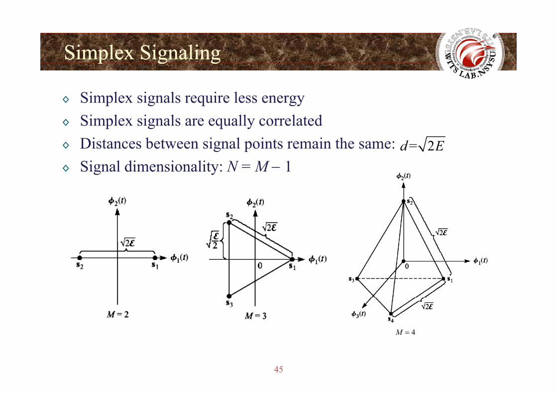
Simplex SignalingSimplex Signalingp g gp g g
◊ Simplex signals require less energy◊ Simplex signals are equally correlated◊ Distances between signal points remain the same: = 2d E◊ Signal dimensionality: N = M − 1
4M
45
4M =
ComparisonsComparisonspp
◊ The signal space dimensionality of the class of orthogonal, biorthogonal, and simplex signals is highly dependent on the constellation size.
hi i i A S d QA◊ This is in contrast to PAM, PSK, and QAM systems.
F fi d E th i i di t i th t i◊ For fixed Eb, the minimum distance in these systems increases with increasing M.◊ This is in sharp contrast to PAM PSK and QAM signaling◊ This is in sharp contrast to PAM, PSK, and QAM signaling.
46
Signal Waveforms from Binary CodesSignal Waveforms from Binary Codesg yg y
◊ Signaling wave forms generated from M binary code words
◊ , for all m and j1 2[ ], 1, 2,...,m m m mNc c c m M= =c
{0,1}mjc ∈
◊ Each component of a code word is mapped to a BPSK waveform:1 2 / cos 2 , 0mj c c c cc E T f t t Tπ= ⇒ ≤ ≤
◊ Tc = T/N0 2 / cos 2 , 0mj c c c cc E T f t t Tπ= ⇒ − ≤ ≤
◊ Ec = E/N◊ The M code words {cm} are mapped to a set of M waveforms
{ (t)} hi h h t f{sm(t)}, which have vector forms
f ll d j1 2[ ], 1, 2,...,m m m mNs s s m M= =s
47
◊ , for all m and j/mjs E N= ±
Signal Waveforms from Binary CodesSignal Waveforms from Binary Codesg yg y
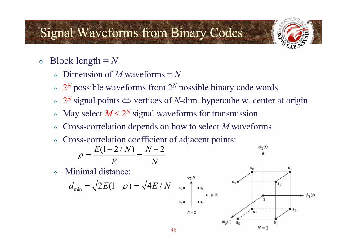
◊ Block length = N◊ Dimension of M waveforms = N◊ 2N possible waveforms from 2N possible binary code words◊ 2N signal points ⇔ vertices of N-dim. hypercube w. center at origin◊ May select M < 2N signal waveforms for transmission◊ Cross-correlation depends on how to select M waveforms◊ Cross-correlation coefficient of adjacent points:
(1 2 / ) 2E N N− −
◊ Minimal distance:
(1 2 / ) 2E N NE N
ρ = =
min 2 (1 ) 4 /d E E Nρ= − =
48
Chapter 3.3: Signaling Schemes with Memory
Wireless Information Transmission System Lab.Wireless Information Transmission System Lab.Institute of Communications EngineeringInstitute of Communications Engineering
Memory
g gg gNational Sun National Sun YatYat--sensen UniversityUniversity
49
Signaling Schemes with MemorySignaling Schemes with Memoryg g yg g y
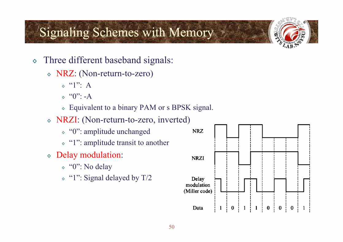
◊ Three different baseband signals:◊ NRZ: (Non-return-to-zero)
◊ “1”: A“0” A◊ “0”: -A
◊ Equivalent to a binary PAM or s BPSK signal.◊ NRZI: (Non-return-to-zero inverted)◊ NRZI: (Non return to zero, inverted)
◊ “0”: amplitude unchanged◊ “1”: amplitude transit to another
◊ Delay modulation:◊ “0”: No delay
“1” Si l d l d b T/2◊ “1”: Signal delayed by T/2
50
Signaling Schemes with MemorySignaling Schemes with Memoryg g yg g y
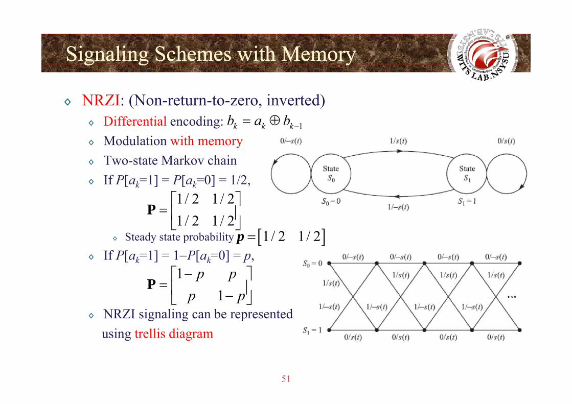
◊ NRZI: (Non-return-to-zero, inverted)◊ Differential encoding: ◊ Modulation with memory
T M k h i
1k k kb a b −= ⊕
◊ Two-state Markov chain◊ If P[ak=1] = P[ak=0] = 1/2,
1/ 2 1/ 2⎡ ⎤
◊ Steady state probability
1/ 2 1/ 21/ 2 1/ 2
⎡ ⎤= ⎢ ⎥
⎣ ⎦P
[ ]1/ 2 1/ 2=p◊ If P[ak=1] = 1−P[ak=0] = p,
11
p pp p
−⎡ ⎤= ⎢ ⎥
⎣ ⎦P
◊ NRZI signaling can be representedusing trellis diagram
1p p⎢ ⎥−⎣ ⎦
51
g g
CPFSKCPFSK
◊ Continuous-Phase Frequency-Shift Keying (CPFSK)◊ The phase of signal is constrained to be continuous◊ Conventional FSK:
◊ Shifting the carrier by◊ Switching one oscillators to another results in relative large spectral
, 1m f m MΔ ≤ ≤
side lobes ⇒ requires large frequency band◊ To avoid large side lobe, the information-bearing frequency modulates
a single carrier whose frequency is changed continuouslya single carrier whose frequency is changed continuously⇒ The signal is phase-continuous⇒ Continuous-phase FSK (CPFSK)⇒ Continuous phase FSK (CPFSK)⇒ The modulation has memory because the phase of the carrier is
constrained to be continuous
52
CPFSKCPFSK
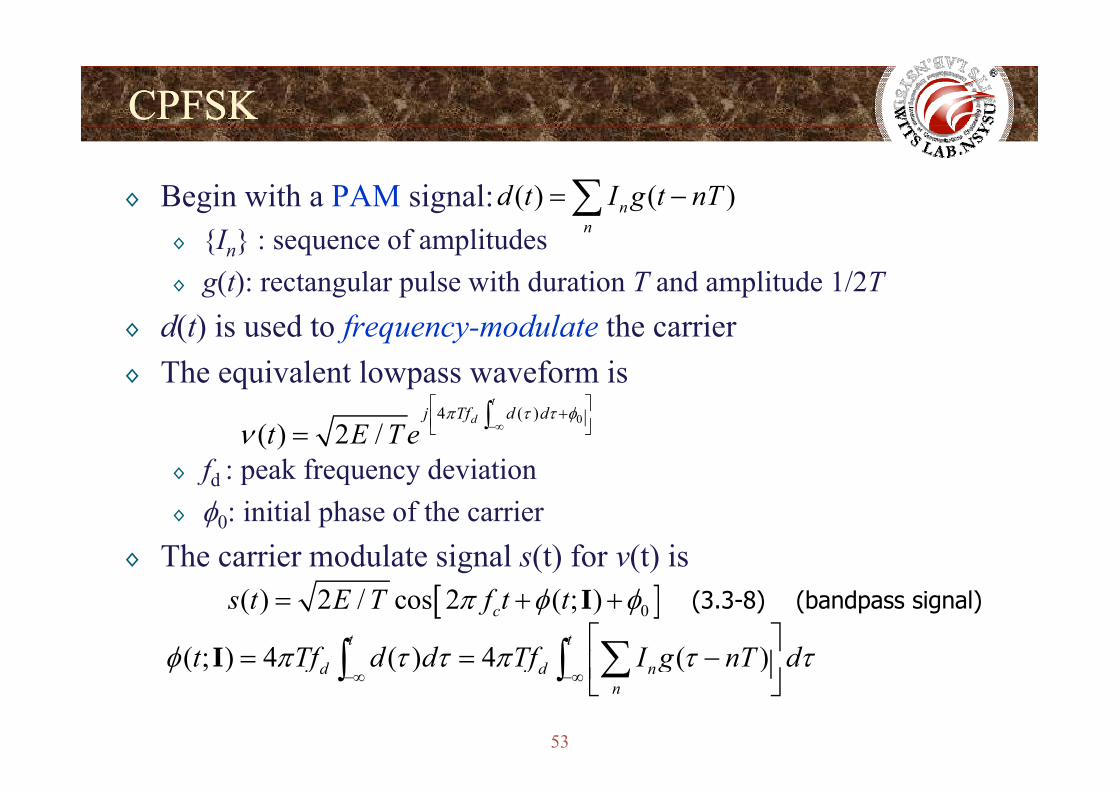
◊ Begin with a PAM signal: ( ) ( )nd t I g t nT= −∑◊ {In} : sequence of amplitudes ◊ g(t): rectangular pulse with duration T and amplitude 1/2T
n
◊ d(t) is used to frequency-modulate the carrier◊ The equivalent lowpass waveform is
⎡ ⎤
◊ fd : peak frequency deviation
04 ( )( ) 2 /
tdj Tf d d
t E T eπ τ τ φ
ν −∞
⎡ ⎤+⎢ ⎥⎣ ⎦∫=d
◊ φ0: initial phase of the carrier◊ The carrier modulate signal s(t) for v(t) is
[ ]0( ) 2 / cos 2 ( ; )cs t E T f t tπ φ φ= + +I
( ; ) 4 ( ) 4 ( )t t
d dt Tf d d Tf I g nT dφ π τ τ π τ τ⎡ ⎤= = −⎢ ⎥∑∫ ∫I
(bandpass signal)(3.3-8)
53
( ; ) 4 ( ) 4 ( )d d nn
t Tf d d Tf I g nT dφ π τ τ π τ τ−∞ −∞ ⎢ ⎥⎣ ⎦
∑∫ ∫I
CPFSKCPFSK
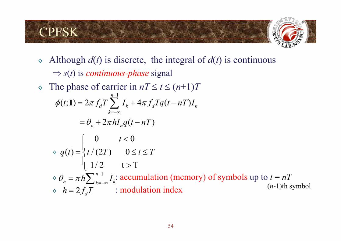
◊ Although d(t) is discrete, the integral of d(t) is continuous⇒ s(t) is continuous-phase signal
◊ The phase of carrier in nT ≤ t ≤ (n+1)T11
( ; ) 2 4 ( )
2 ( )
n
d k d nk
t f T I f Tq t nT I
hI t T
φ π π
θ
−
=−∞
= + −
+
∑I
2 ( )n n hI q t nTθ π= + −
0 0 t <⎧⎪
◊
l ti ( ) f b l t t T
( ) / (2 ) 0 1/ 2 t T
q t t T t T⎪= ≤ ≤⎨⎪ >⎩
1nh Iθ −∑◊ : accumulation (memory) of symbols up to t = nT◊ : modulation index
1nn kk
h Iθ π=−∞
= ∑2 dh f T= (n-1)th symbol
54
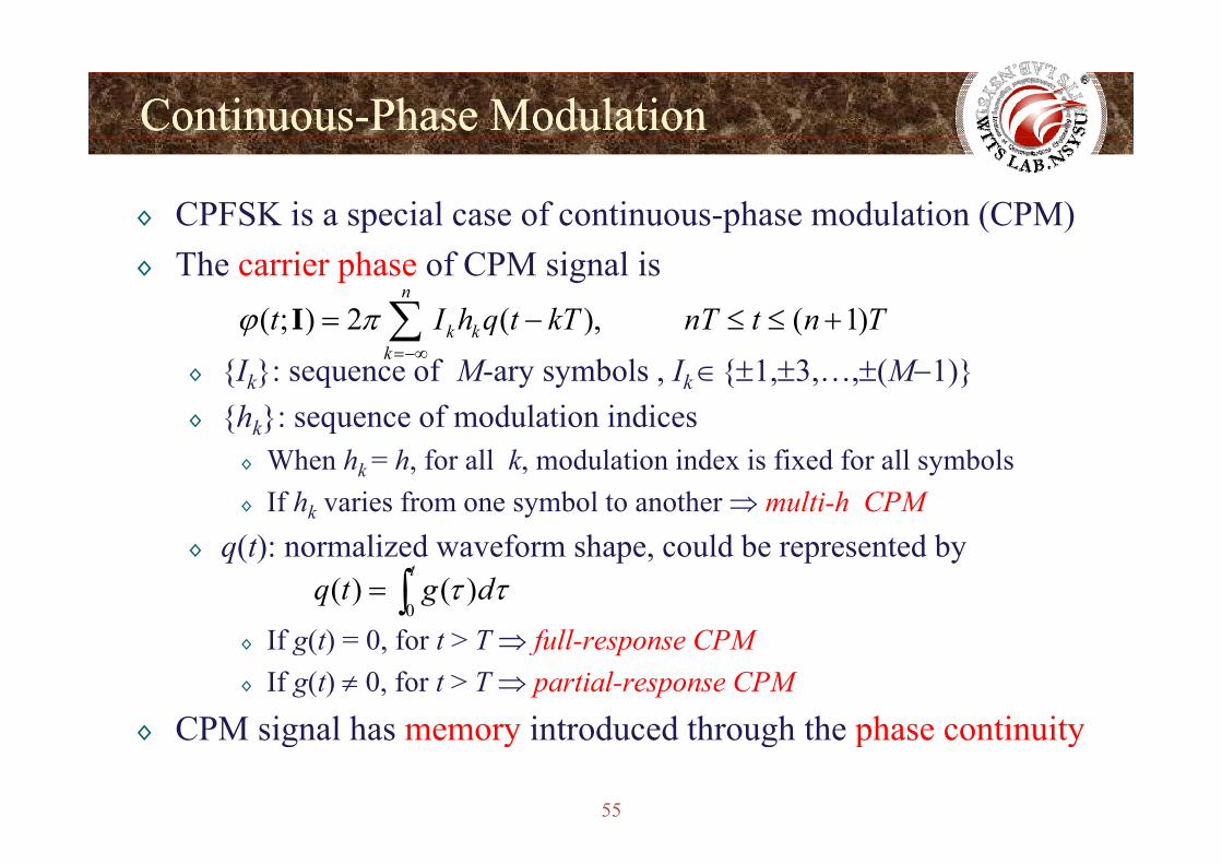
ContinuousContinuous--Phase ModulationPhase Modulation
◊ CPFSK is a special case of continuous-phase modulation (CPM)◊ The carrier phase of CPM signal is
( ; ) 2 ( ), ( 1)n
k kt I h q t kT nT t n Tϕ π= − ≤ ≤ +∑I
◊ {Ik}: sequence of M-ary symbols , Ik ∈{±1,±3,…,±(M−1)}◊ {hk}: sequence of modulation indices
( ; ) ( ), ( )k kk
qϕ=−∞∑
{ k} q◊ When hk = h, for all k, modulation index is fixed for all symbols◊ If hk varies from one symbol to another ⇒ multi-h CPM
◊ q(t): normalized waveform shape, could be represented by
0( ) ( )
tq t g dτ τ= ∫
◊ If g(t) = 0, for t > T ⇒ full-response CPM◊ If g(t) ≠ 0, for t > T ⇒ partial-response CPM
◊ CPM signal has memory introduced through the phase continuity
55
◊ CPM signal has memory introduced through the phase continuity
ContinuousContinuous--Phase ModulationPhase Modulation
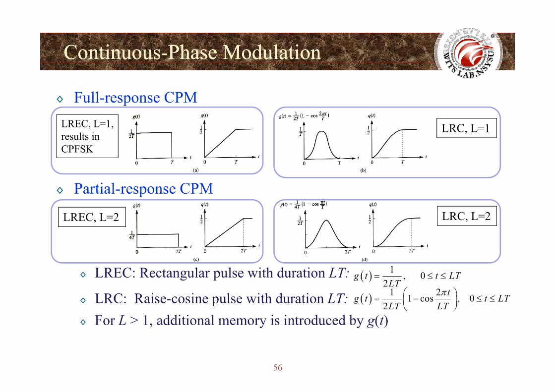
◊ Full-response CPMLREC, L=1, results in CPFSK
LRC, L=1
◊ Partial-response CPM
CPFSK
p
LREC, L=2 LRC, L=2
◊ LREC: Rectangular pulse with duration LT: ( ) 1 , 02
g t t LTLT
= ≤ ≤
◊ LRC: Raise-cosine pulse with duration LT:◊ For L > 1, additional memory is introduced by g(t)
( ) 1 21 cos , 02
tg t t LTLT LT
π⎛ ⎞= − ≤ ≤⎜ ⎟⎝ ⎠
2LT
56
ContinuousContinuous--Phase ModulationPhase Modulation
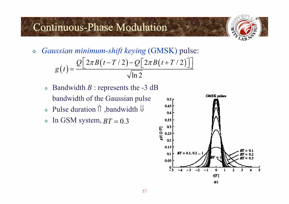
◊ Gaussian minimum-shift keying (GMSK) pulse:
( )( ) ( )2 / 2 2 / 2
ln 2
Q B t T Q B t Tg t
π π⎡ ⎤− − +⎡ ⎤⎣ ⎦⎣ ⎦=
◊ Bandwidth B : represents the -3 dBbandwidth of the Gaussian pulsep
◊ Pulse duration ⇑ ,bandwidth ⇓◊ In GSM system, 0.3BT =
57
ContinuousContinuous--Phase ModulationPhase Modulation
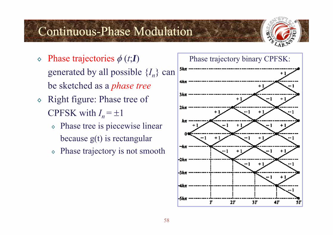
◊ Phase trajectories φ (t;I) Phase trajectory binary CPFSK:
generated by all possible {In} canbe sketched as a phase tree
◊ Right figure: Phase tree of CPFSK with In = ±1n ◊ Phase tree is piecewise linear
because g(t) is rectangular◊ Phase trajectory is not smooth
58
ContinuousContinuous--Phase ModulationPhase Modulation
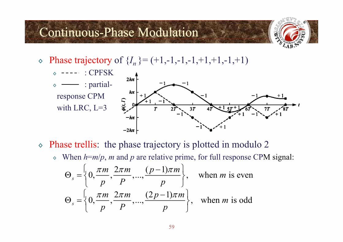
◊ Phase trajectory of {In }= (+1,-1,-1,-1,+1,+1,-1,+1)◊ : CPFSK◊ : partial-
CPMresponse CPM with LRC, L=3
◊ Phase trellis: the phase trajectory is plotted in modulo 2p j y p◊ When h=m/p, m and p are relative prime, for full response CPM signal:
2 ( 1)0 when is evenm m p m mπ π π⎧ ⎫−Θ = ⎨ ⎬0, , ,..., , when is evens m
p P pΘ = ⎨ ⎬
⎩ ⎭2 (2 1)0, , ,..., , when is odds
m m p m mπ π π⎧ ⎫−Θ = ⎨ ⎬
59
, , , , ,s p P p⎨ ⎬⎩ ⎭
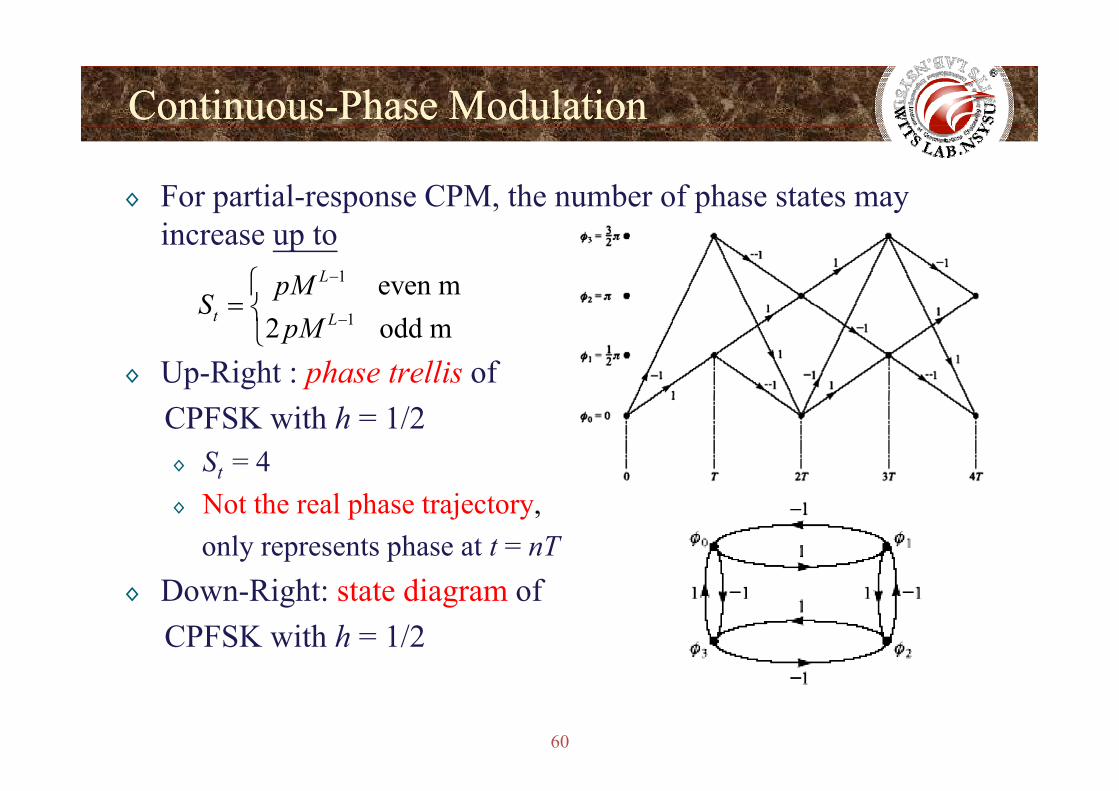
ContinuousContinuous--Phase ModulationPhase Modulation
◊ For partial-response CPM, the number of phase states may increase up to
1 even mLpMS
−⎧= ⎨
◊ Up-Right : phase trellis of
12 odd m t LS
pM −= ⎨
⎩
CPFSK with h = 1/2◊ St = 4◊ Not the real phase trajectory,
only represents phase at t = nT◊ Down-Right: state diagram of
CPFSK with h = 1/2
60
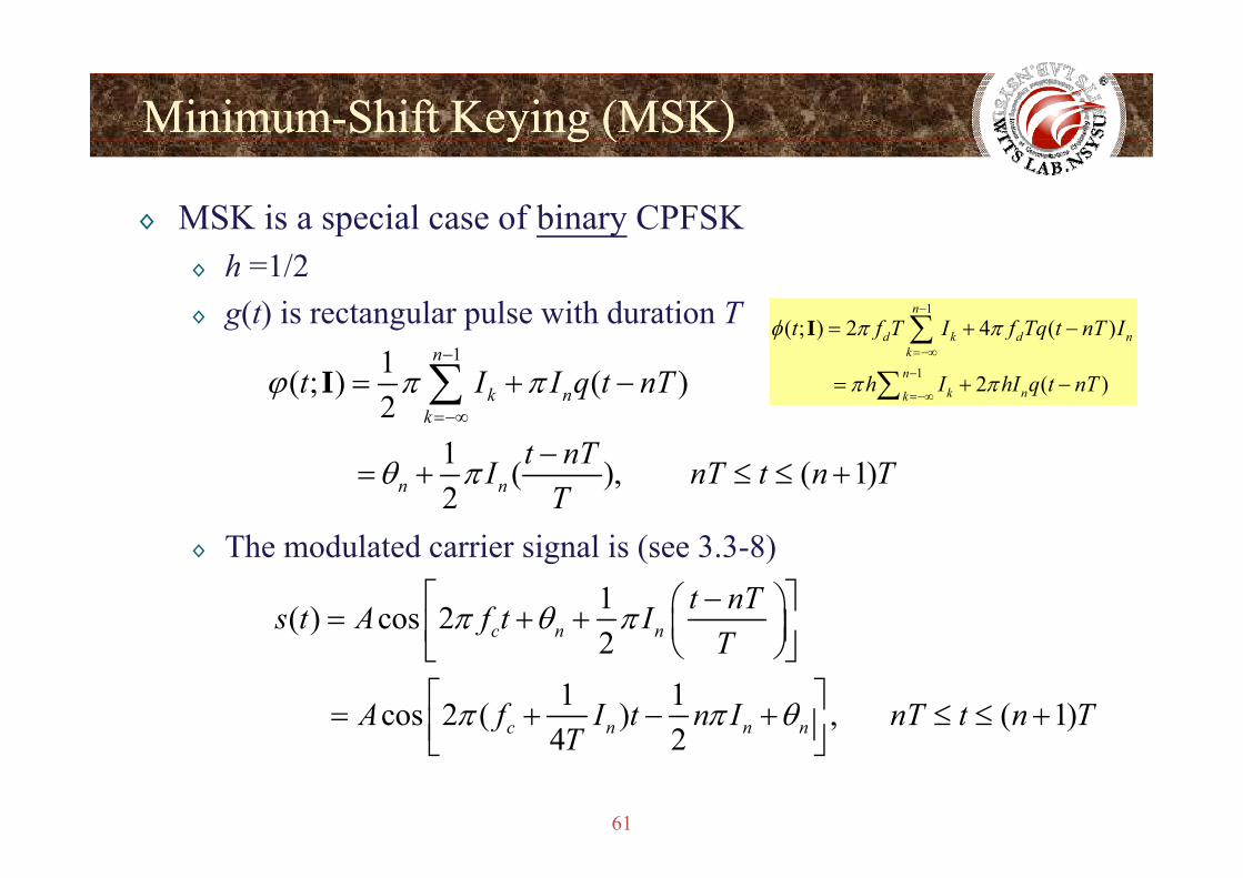
MinimumMinimum--Shift Keying (MSK)Shift Keying (MSK)y g ( )y g ( )
◊ MSK is a special case of binary CPFSK◊ h =1/2◊ g(t) is rectangular pulse with duration T 1
( ; ) 2 4 ( )n
d k d nt f T I f Tq t nT Iφ π π−
= + −∑I11( ; ) ( )
2
n
k nk
t I I q t nTϕ π π−
=−∞
= + −∑I 1
( ) ( )
2 ( )
d k d nk
nk nk
f f q
h I hI q t nT
φ
π π=−∞
−
=−∞= + −
∑
∑
Th d l t d i i l i ( 3 3 8)
1 ( ), ( 1)2n n
t nTI nT t n TT
θ π −= + ≤ ≤ +
◊ The modulated carrier signal is (see 3.3-8)1( ) cos 22c n n
t nTs t A f t IT
π θ π⎡ − ⎤⎛ ⎞= + + ⎜ ⎟⎢ ⎥⎝ ⎠⎣ ⎦21 1 cos 2 ( ) , ( 1)
4 2c n n n
T
A f I t n I nT t n TT
π π θ
⎜ ⎟⎢ ⎥⎝ ⎠⎣ ⎦⎡ ⎤= + − + ≤ ≤ +⎢ ⎥⎣ ⎦
61
4 2T⎢ ⎥⎣ ⎦
MinimumMinimum--Shift Keying (MSK)Shift Keying (MSK)y g ( )y g ( )
◊ The binary CPFSK signal can be expressed as a sinusoid having two possible frequencies in nT ≤ t ≤ (n+1)T
11
4cf fT
= −
Th bi CPFSK i l b i b2
41
4c
T
f fT
= +
◊ The binary CPFSK signal can be written by
11( ) cos 2 ( 1) , 1, 22
ii i ns t A f t n iπ θ π −⎡ ⎤= + + − =⎢ ⎥⎣ ⎦
◊ Equivalent to a FSK signal withI FSK i i f i h li f
( ) ( ) , ,2i i nf⎢ ⎥⎣ ⎦
2 11
2f f f
TΔ = − =
◊ In FSK, minimum frequency separation to ensure orthogonality of the signals is
◊ Thus binary CPFSK with h=1/2 is called minimum-shift keying
2T1
2f
TΔ =
62
◊ Thus, binary CPFSK with h 1/2 is called minimum-shift keying
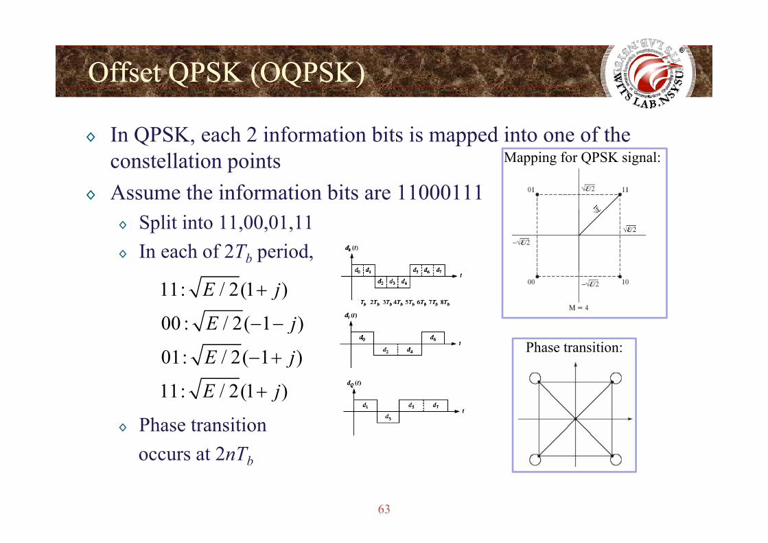
Offset QPSK (OQPSK)Offset QPSK (OQPSK)Q ( Q )Q ( Q )
◊ In QPSK, each 2 information bits is mapped into one of the constellation points
◊ Assume the information bits are 11000111
Mapping for QPSK signal:
◊ Split into 11,00,01,11◊ In each of 2Tb period,
11: / 2(1 )
00 : / 2( 1 )
E j
E j
+
− −( )
01: / 2( 1 )
11: / 2(1 )
j
E j
E j
− +
+
Phase transition:
◊ Phase transition occurs at 2nTb
11: / 2(1 )E j+
63
occurs at 2nTb
Offset QPSK (OQPSK)Offset QPSK (OQPSK)Q ( Q )Q ( Q )
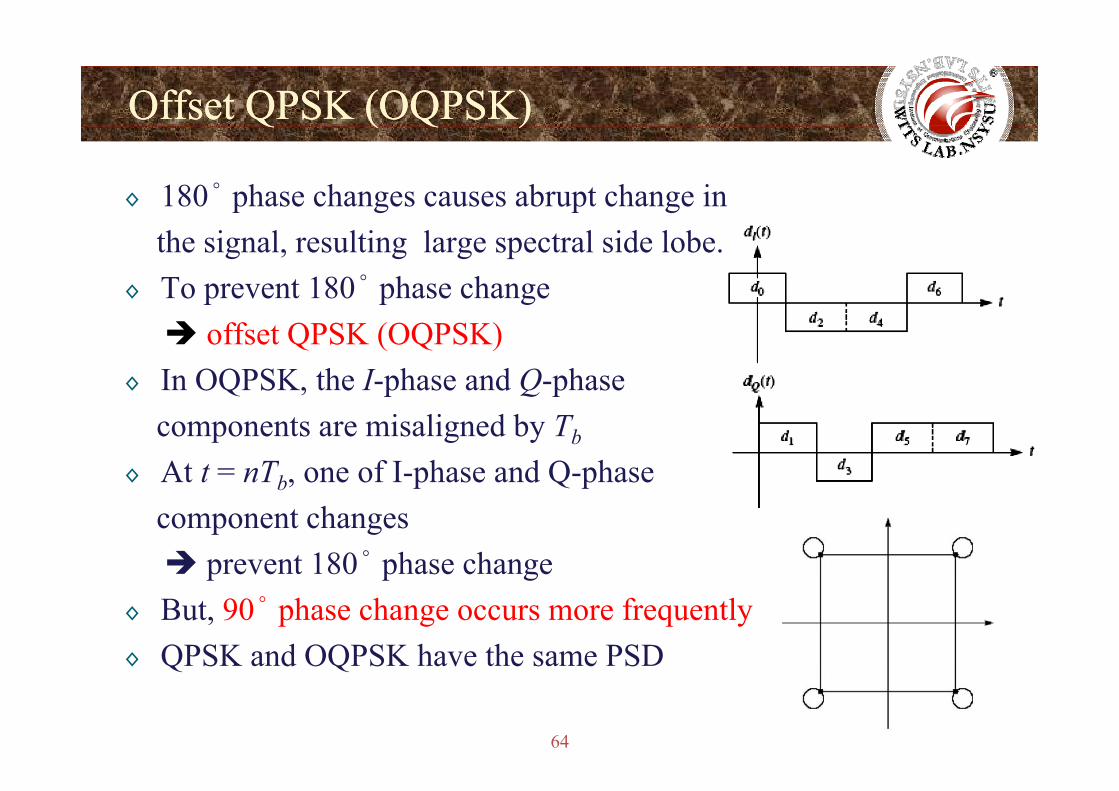
◊ 180° phase changes causes abrupt change inthe signal, resulting large spectral side lobe.
◊ To prevent 180° phase changeoffset QPSK (OQPSK)
◊ In OQPSK, the I-phase and Q-phase Q p Q pcomponents are misaligned by Tb
◊ At t = nTb, one of I-phase and Q-phaseb, p Q pcomponent changes
prevent 180° phase changep p g◊ But, 90° phase change occurs more frequently◊ QPSK and OQPSK have the same PSD
64
◊ QPSK and OQPSK have the same PSD
Offset QPSK (OQPSK)Offset QPSK (OQPSK)Q ( Q )Q ( Q )
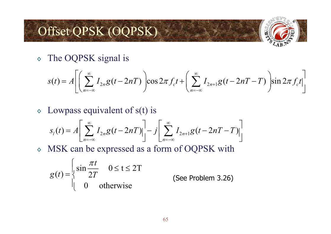
◊ The OQPSK signal is
2 2 1( ) ( 2 ) cos 2 ( 2 ) sin 2n c n cn n
s t A I g t nT f t I g t nT T f tπ π∞ ∞
+=−∞ =−∞
⎡ ⎤⎛ ⎞ ⎛ ⎞= − + − −⎢ ⎥⎜ ⎟ ⎜ ⎟⎝ ⎠ ⎝ ⎠⎣ ⎦∑ ∑
◊ Lowpass equivalent of s(t) is
n n=−∞ =−∞⎝ ⎠ ⎝ ⎠⎣ ⎦
2 2 1( ) ( 2 ) ( 2 )l n nn n
s t A I g t nT j I g t nT T∞ ∞
+=−∞ =−∞
⎡ ⎤ ⎡ ⎤= − − − −⎢ ⎥ ⎢ ⎥⎣ ⎦ ⎣ ⎦
∑ ∑◊ MSK can be expressed as a form of OQPSK with
sin 0 t 2Ttπ⎧ ≤ ≤⎪sin 0 t 2T( ) 2
0 otherwise g t T
≤ ≤⎪= ⎨⎪⎩
(See Problem 3.26)
65
Offset QPSK (OQPSK)Offset QPSK (OQPSK)Q ( Q )Q ( Q )
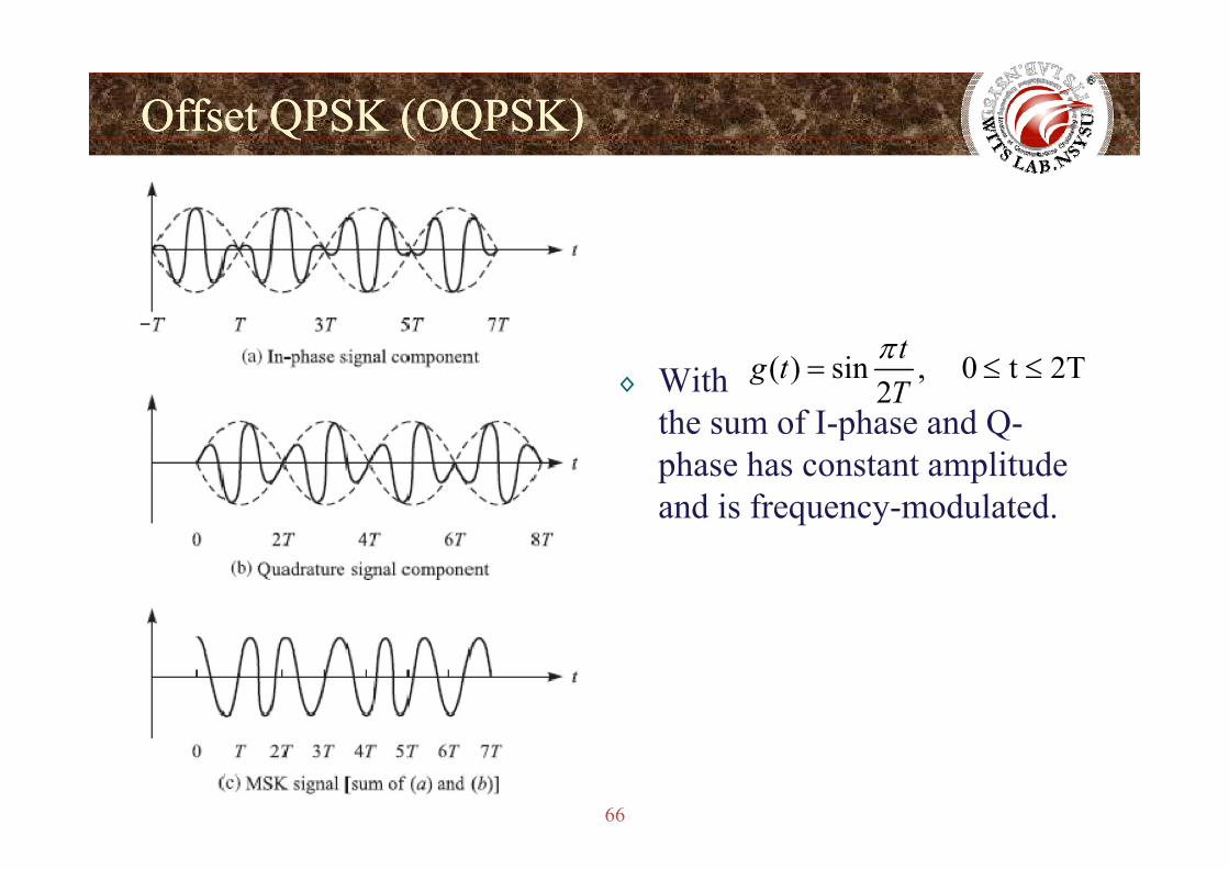
◊ With the sum of I-phase and Q-
( ) sin , 0 t 2T2
tg tT
π= ≤ ≤
p Qphase has constant amplitude and is frequency-modulated.
66
Offset QPSK (OQPSK)Offset QPSK (OQPSK)Q ( Q )Q ( Q )
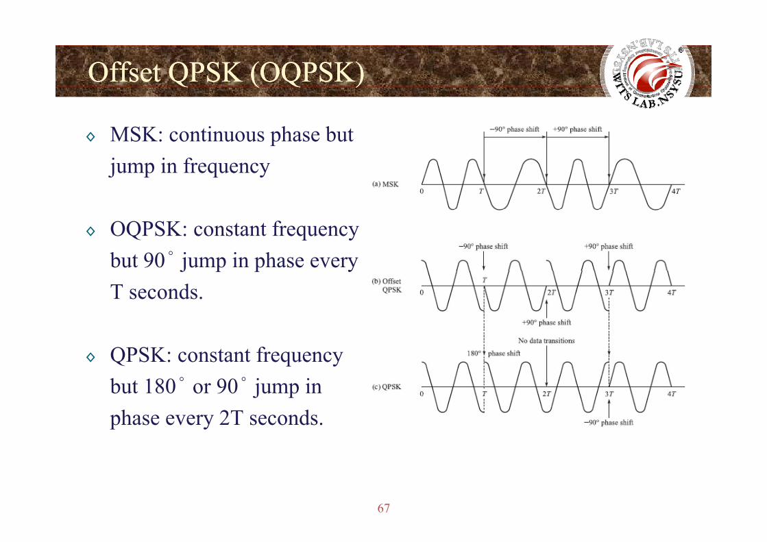
◊ MSK: continuous phase but jump in frequency
◊ OQPSK: constant frequency but 90° jump in phase everyj p p yT seconds.
◊ QPSK: constant frequency but 180° or 90° jump in j pphase every 2T seconds.
67
Linear Representation of CPM SignalsLinear Representation of CPM Signalsp gp g
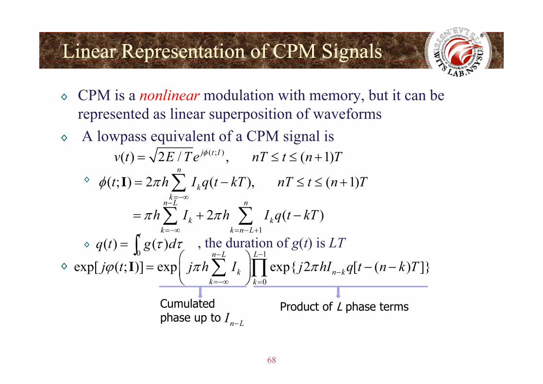
◊ CPM is a nonlinear modulation with memory, but it can be represented as linear superposition of waveforms
◊ A lowpass equivalent of a CPM signal is
◊
( ; )( ) 2 / , ( 1)j t Iv t E T e nT t n Tφ= ≤ ≤ +
( ; ) 2 ( ), ( 1)n
kt h I q t kT nT t n Tφ π= − ≤ ≤ +∑Ik =−∞
1 2 ( )
n L n
k kk k n L
h I h I q t kTπ π−
=−∞ = − +
= + −∑ ∑t
∫◊ , the duration of g(t) is LT◊
0( ) ( )
tq t g dτ τ= ∫ 1
0
exp[ ( ; )] exp exp{ 2 [ ( ) ]}Ln L
k n kk k
j t j h I j hI q t n k Tϕ π π−−
−⎛ ⎞
= − −⎜ ⎟⎝ ⎠
∑ ∏I0k k=−∞ =⎝ ⎠
Cumulated phase up to
Product of L phase termsn LI
68
p p n L−
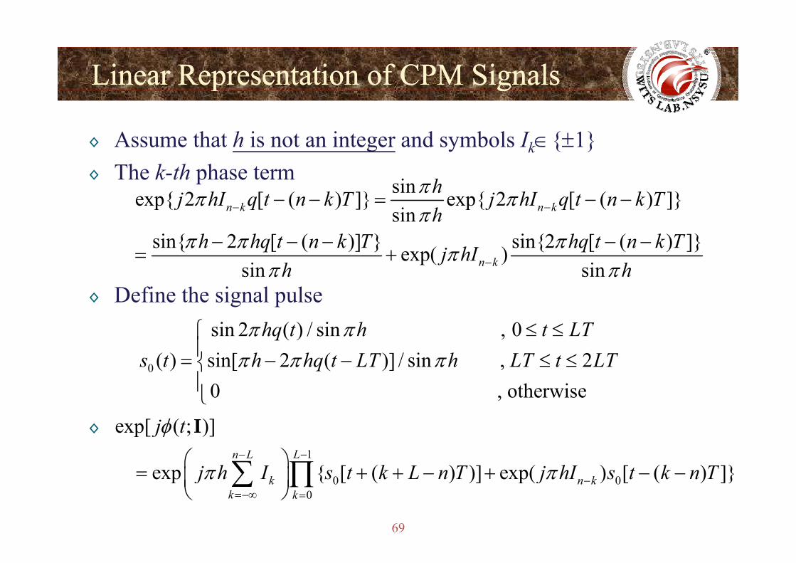
Linear Representation of CPM SignalsLinear Representation of CPM Signalsp gp g
◊ Assume that h is not an integer and symbols Ik∈{±1}◊ The k-th phase term sinexp{ 2 [ ( ) ]} exp{ 2 [ ( ) ]}
sinn k n khj hI q t n k T j hI q t n k Th
ππ ππ− −− − = − −
sinsin{ 2 [ ( )] } sin{2 [ ( ) ]}exp( )
sin sinn k
hh hq t n k T hq t n k Tj hI
h h
ππ π ππ
π π−
− − − − −= +
◊ Define the signal pulsesin 2 ( ) / sin , 0 hq t h t LTπ π ≤ ≤⎧
⎪0 ( ) sin[ 2 ( )] / sin , 2
0 , otherwise s t h hq t LT h LT t LTπ π π⎪= − − ≤ ≤⎨
⎪⎩
◊
1
exp[ ( ; )]
exp { [ ( ) )] exp( ) [ ( ) ]}Ln L
j t
j h I s t k L n T j hI s t k n T
φ
π π−−⎛ ⎞= + + − + − −⎜ ⎟∑ ∏
I
69
0 00
exp { [ ( ) )] exp( ) [ ( ) ]}k n kk k
j h I s t k L n T j hI s t k n Tπ π −=−∞ =
= + + − + − −⎜ ⎟⎝ ⎠
∑ ∏
Linear Representation of CPM SignalsLinear Representation of CPM Signalsp gp g
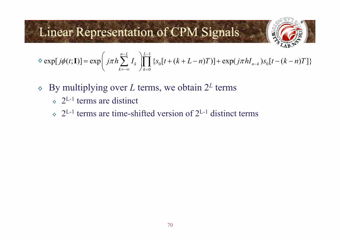
◊1
0 0exp[ ( ; )] exp { [ ( ) )] exp( ) [ ( ) ]}Ln L
k n kj t j h I s t k L n T j hI s t k n Tφ π π−−
−⎛ ⎞
= + + − + − −⎜ ⎟⎝ ⎠
∑ ∏I
◊ By multiplying over L terms, we obtain 2L terms
0k k=−∞ =⎜ ⎟⎝ ⎠
∑ ∏
◊ 2L-1 terms are distinct◊ 2L-1 terms are time-shifted version of 2L-1 distinct terms
70
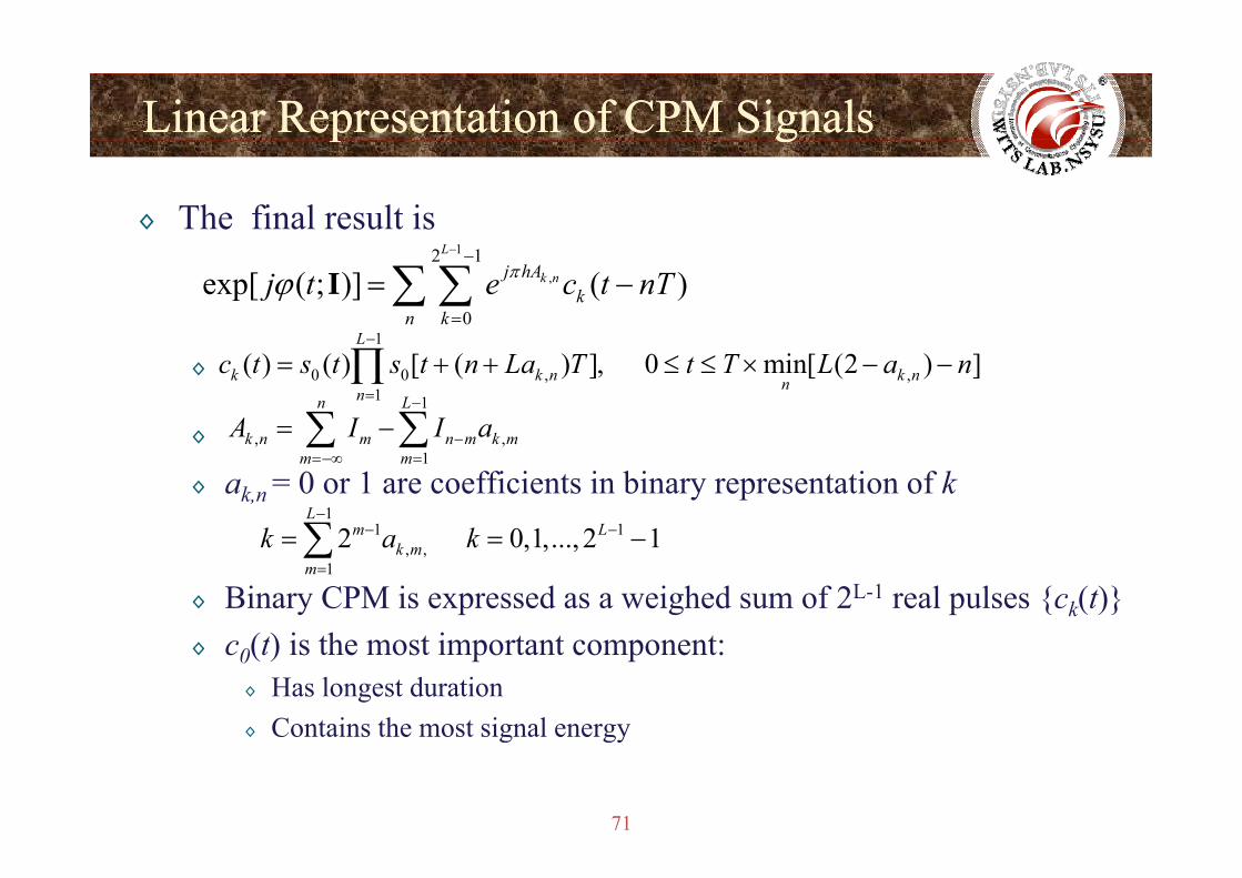
Linear Representation of CPM SignalsLinear Representation of CPM Signalsp gp g
◊ The final result is 1
,2 1
0
exp[ ( ; )] ( )L
k nj hAk
n k
j t e c t nTπϕ− −
=
= −∑ ∑I1L−
◊
◊
1
0 0 , ,1
( ) ( ) [ ( ) ], 0 min[ (2 ) ]L
k k n k nnn
c t s t s t n La T t T L a n−
=
= + + ≤ ≤ × − −∏1n L
k n m n m k mA I I a−
= −∑ ∑◊
◊ ak,n = 0 or 1 are coefficients in binary representation of k, ,
1k n m n m k m
m m−
=−∞ =∑ ∑
11 12 0 1 2 1
Lm Lk a k
−− −= =∑
◊ Binary CPM is expressed as a weighed sum of 2L-1 real pulses {ck(t)}(t) i th t i t t t
, ,12 0,1,..., 2 1k m
mk a k
=
= = −∑
◊ c0(t) is the most important component:◊ Has longest duration◊ Contains the most signal energy
71
g gy
Pulse Code ModulationPulse Code Modulation(Line Code)
Wireless Information Transmission System Lab.Wireless Information Transmission System Lab.Institute of Communications EngineeringInstitute of Communications Engineeringg gg gNational Sun National Sun YatYat--sensen UniversityUniversity
72
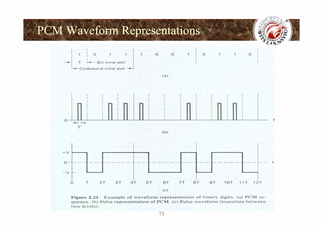
PCM Waveform RepresentationsPCM Waveform Representationspp
73
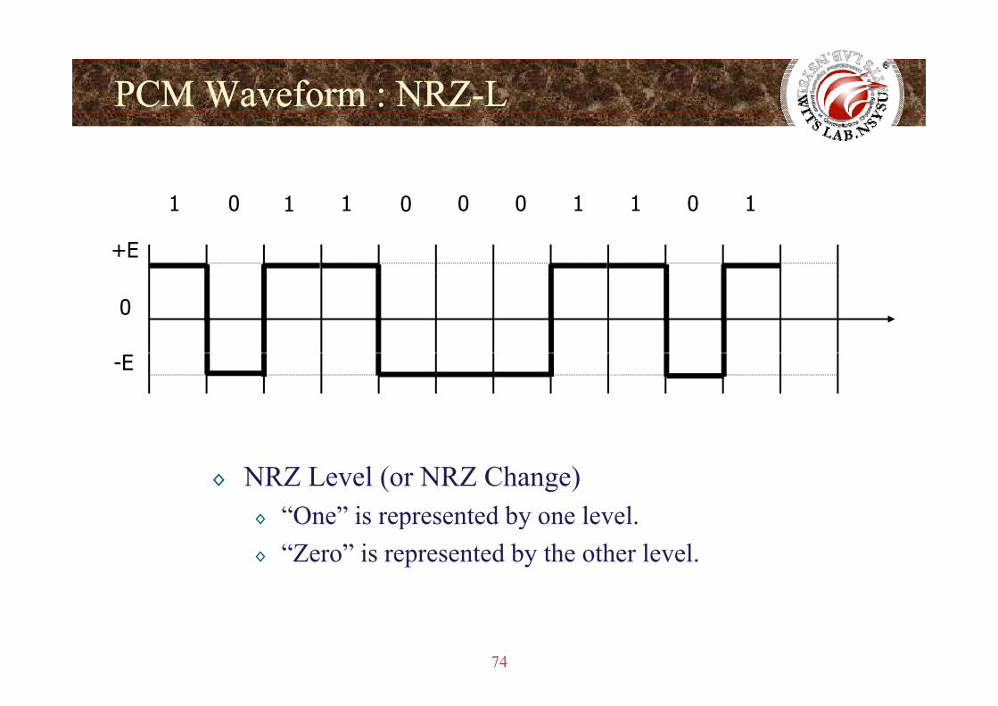
PCM Waveform : NRZPCM Waveform : NRZ--LL
1 0 1 1 0 0 0 1 1 0 1
+E
0
-E
◊ NRZ Level (or NRZ Change)“One” is represented by one level◊ One is represented by one level.
◊ “Zero” is represented by the other level.
74
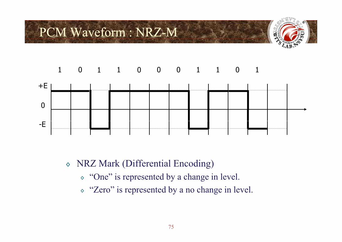
PCM Waveform : NRZPCM Waveform : NRZ--MM
1 0 1 1 0 0 0 1 1 0 1
+E
0
-E
◊ NRZ Mark (Differential Encoding)“One” is represented by a change in level◊ One is represented by a change in level.
◊ “Zero” is represented by a no change in level.
75
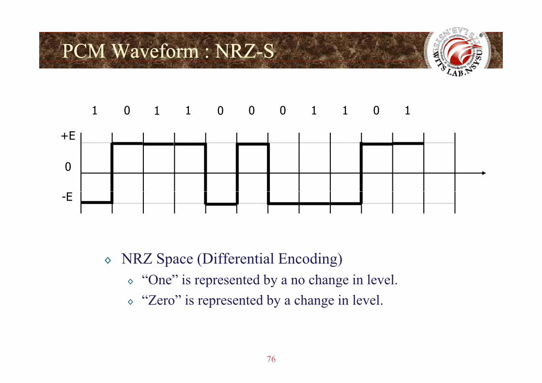
PCM Waveform : NRZPCM Waveform : NRZ--SS
1 0 1 1 0 0 0 1 1 0 1
+E
0
-E
◊ NRZ Space (Differential Encoding)“One” is represented by a no change in level◊ One is represented by a no change in level.
◊ “Zero” is represented by a change in level.
76
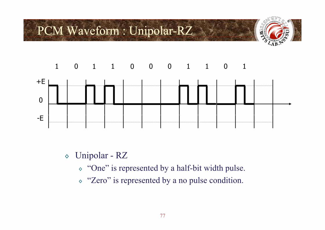
PCM Waveform : UnipolarPCM Waveform : Unipolar--RZRZpp
1 0 1 1 0 0 0 1 1 0 1
+E
0
-E
◊ Unipolar - RZ“One” is represented by a half bit width pulse◊ One is represented by a half-bit width pulse.
◊ “Zero” is represented by a no pulse condition.
77
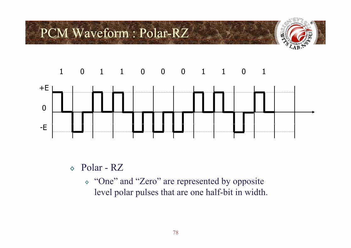
PCM Waveform : PolarPCM Waveform : Polar--RZRZ
1 0 1 1 0 0 0 1 1 0 1
+E
0
-E
◊ Polar - RZ“One” and “Zero” are represented by opposite◊ One and Zero are represented by opposite level polar pulses that are one half-bit in width.
78
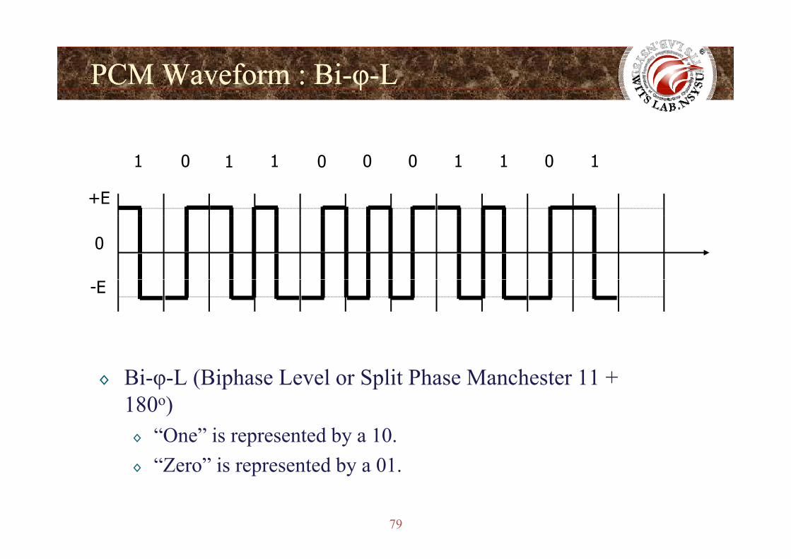
PCM Waveform : BiPCM Waveform : Bi--φφ--LLφφ
1 0 1 1 0 0 0 1 1 0 1
+E
0
-E
◊ Bi-φ-L (Biphase Level or Split Phase Manchester 11 + 180o)180 )◊ “One” is represented by a 10.◊ “Zero” is represented by a 01.
79
◊ Zero is represented by a 01.
PCM Waveform : BiPCM Waveform : Bi--φφ--MMφφ
1 0 1 1 0 0 0 1 1 0 1
+E
0
i ( i h k h 1)
-E
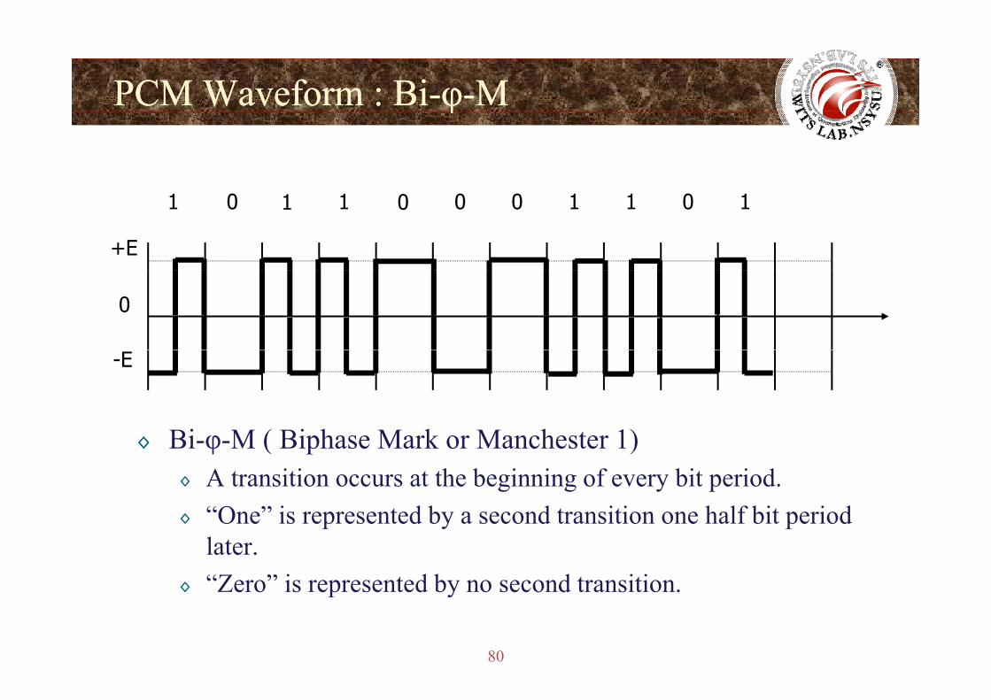
◊ Bi-φ-M ( Biphase Mark or Manchester 1)◊ A transition occurs at the beginning of every bit period.
“O ” i t d b d t iti h lf bit i d◊ “One” is represented by a second transition one half bit period later.
◊ “Zero” is represented by no second transition
80
◊ Zero is represented by no second transition.
PCM Waveform : BiPCM Waveform : Bi--φφ--SSφφ
1 0 1 1 0 0 0 1 1 0 1
+E
0
-E
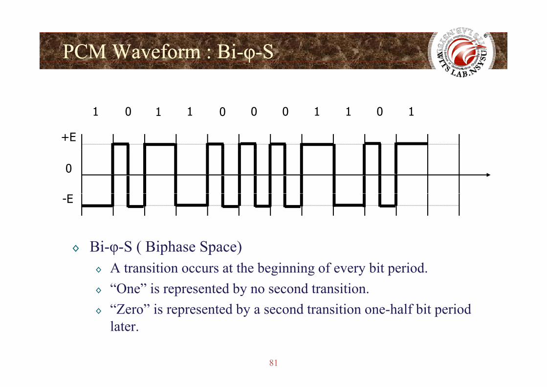
◊ Bi-φ-S ( Biphase Space)◊ A transition occurs at the beginning of every bit period.◊ “One” is represented by no second transition.◊ “Zero” is represented by a second transition one-half bit period
later
81
later.
PCM Waveform : Dicode PCM Waveform : Dicode -- NRZNRZ
1 0 1 1 0 0 0 1 1 0 1
+E
0
-E
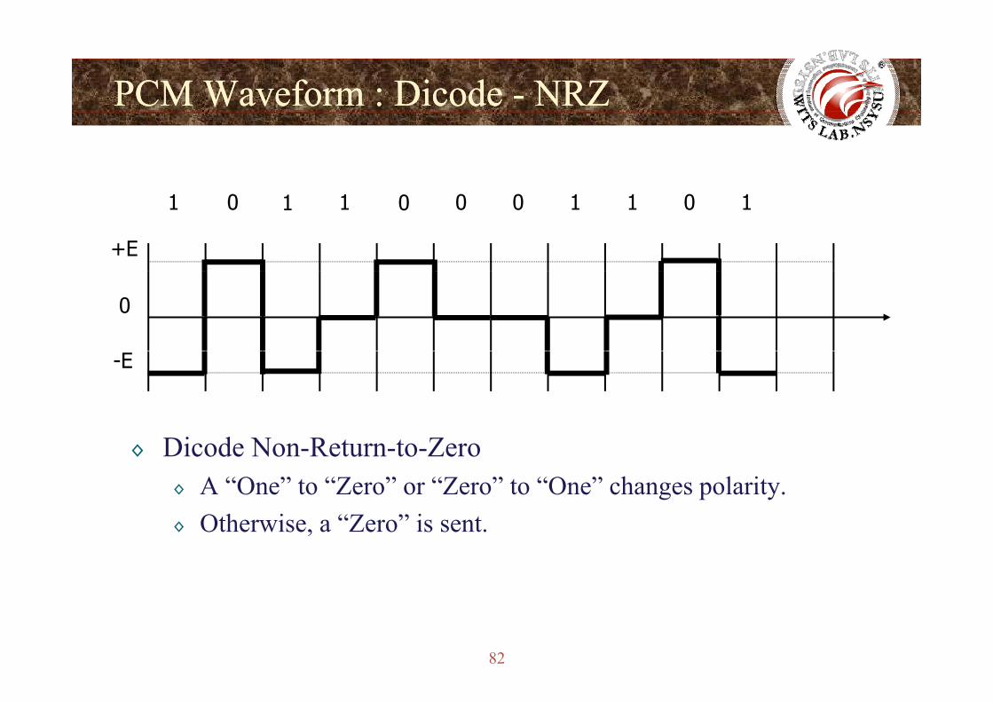
◊ Dicode Non-Return-to-Zero◊ A “One” to “Zero” or “Zero” to “One” changes polarity.◊ Otherwise, a “Zero” is sent.
82
PCM Waveform : Dicode PCM Waveform : Dicode -- RZRZ
1 0 1 1 0 0 0 1 1 0 1
+E
0
-E
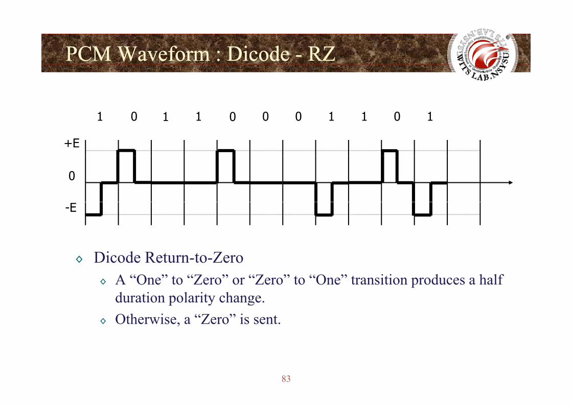
◊ Dicode Return-to-Zero◊ A “One” to “Zero” or “Zero” to “One” transition produces a half
d ti l it hduration polarity change.◊ Otherwise, a “Zero” is sent.
83
PCM Waveform : Delay ModePCM Waveform : Delay Modeyy
1 0 1 1 0 0 0 1 1 0 1
+E
0
-E
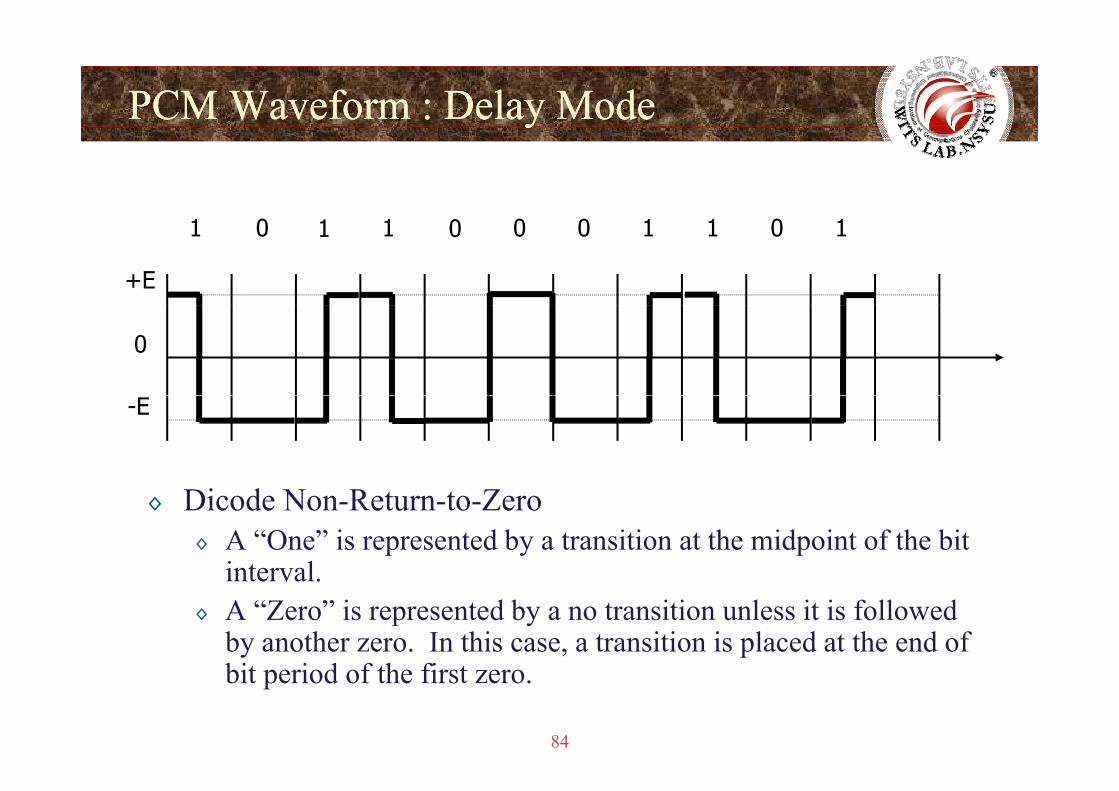
◊ Dicode Non-Return-to-Zero◊ A “One” is represented by a transition at the midpoint of the bit
intervalinterval.◊ A “Zero” is represented by a no transition unless it is followed
by another zero. In this case, a transition is placed at the end of bi i d f h fi
84
bit period of the first zero.
Line Code: 4B3TLine Code: 4B3T
O - -
85
Line Code: 4B3TLine Code: 4B3T
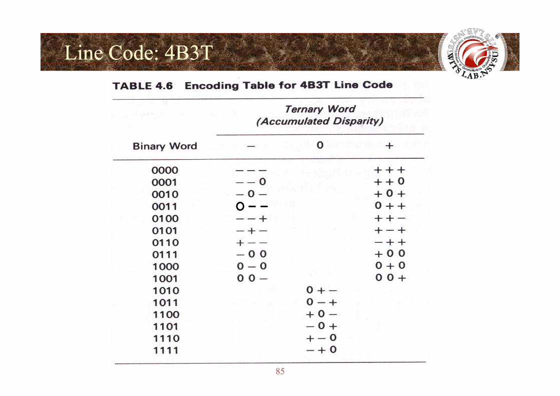
◊ Ternary words in the middle column are balanced in their DC content.
◊ Code words from the first and third columns are selected alternately to maintain DC balance.
◊ If more positive pulses than negative pulses have been transmitted, l 1 i l t dcolumn 1 is selected.
◊ Notice that the all-zeros code word is not used.
86
Line Code: Multilevel TransmissionLine Code: Multilevel TransmissionLine Code Multilevel TransmissionLine Code Multilevel Transmission
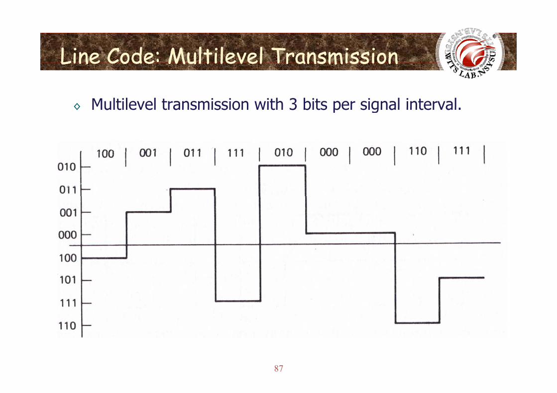
◊ Multilevel transmission with 3 bits per signal interval◊ Multilevel transmission with 3 bits per signal interval.
87
Criteria for Selecting PCM WaveformCriteria for Selecting PCM WaveformCriteria for Selecting PCM WaveformCriteria for Selecting PCM Waveform
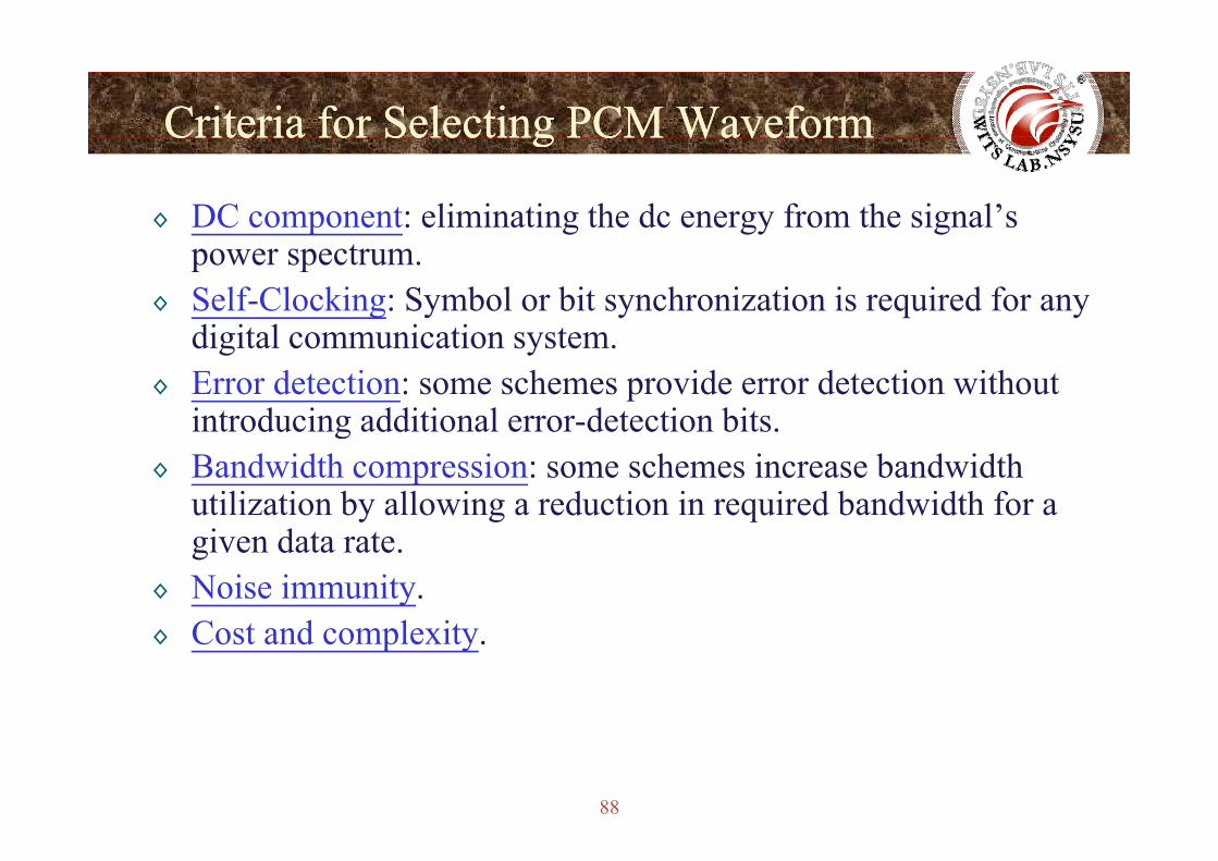
◊ DC component: eliminating the dc energy from the signal’s power spectrum.
◊ Self-Clocking: Symbol or bit synchronization is required for any digital communication systemdigital communication system.
◊ Error detection: some schemes provide error detection without introducing additional error-detection bits.introducing additional error detection bits.
◊ Bandwidth compression: some schemes increase bandwidth utilization by allowing a reduction in required bandwidth for a i dgiven data rate.
◊ Noise immunity.C t d l it◊ Cost and complexity.
88
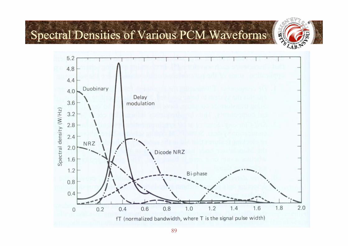
Spectral Densities of Various PCM WaveformsSpectral Densities of Various PCM Waveformspp
89


![II Baseband Modulation Schemes 020206[1]](https://img.pdfslide.us/doc/110x75/577d2a511a28ab4e1ea8f601/ii-baseband-modulation-schemes-0202061.jpg)