Embed Size (px)
Citation preview
06/12/2012
Dobroslav Tsonev, Sinan Sinanović and Harald Haas
Pulse Shaping in Unipolar OFDM-
based Modulation Schemes
Institute of Digital Communications
The University of Edinburgh, UK
06/12/2012 2
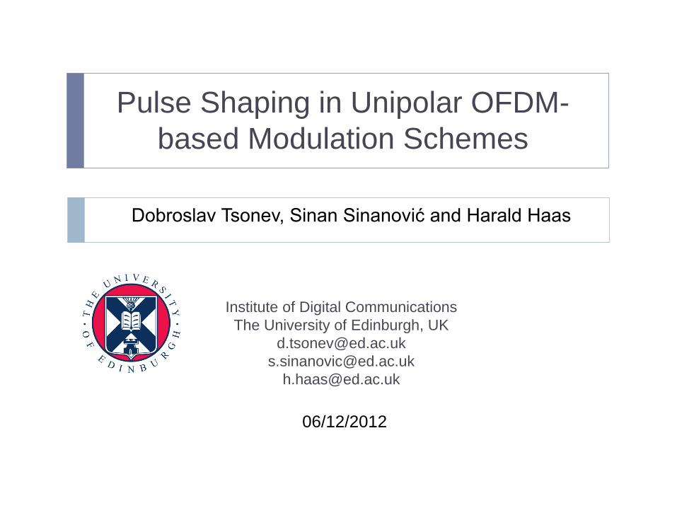
OFDM-based Communication System
Discrete time-domain samples need to be mapped to continuous
time-domain pulse shapes in order to obtain an analog signal
suitable for modulation of a device such as a LED.
Pulse
Shaping
Channel
+
Bit
Stream
OFDM
Modulator
Match
Filter
&
Sample
OFDM
Demodulator
AWGN
Bit
Stream
M-QAM
Modulator
M-QAM
Demodulator
06/12/2012 3
Optical Wireless Communication Based on
OFDM
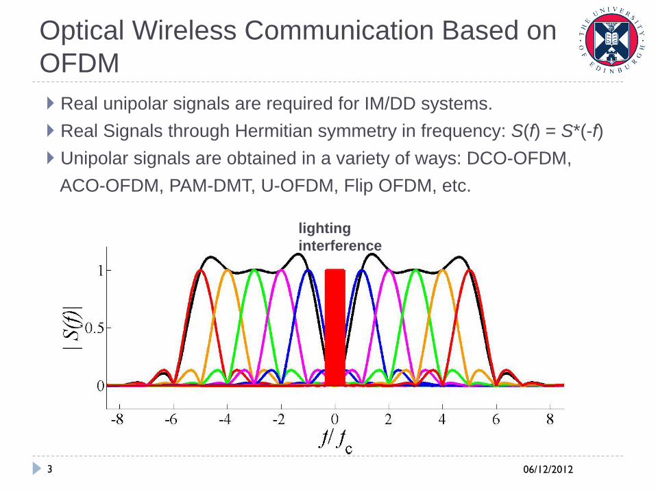
Real unipolar signals are required for IM/DD systems.
Real Signals through Hermitian symmetry in frequency: S(f) = S*(-f)
Unipolar signals are obtained in a variety of ways: DCO-OFDM,
ACO-OFDM, PAM-DMT, U-OFDM, Flip OFDM, etc.
lighting
interference
06/12/2012 4
Unipolar OFDM (U-OFDM) / Flip OFDM
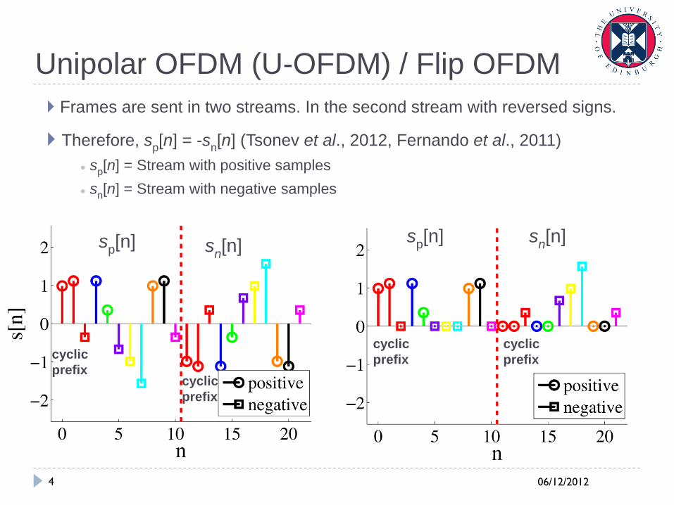
Frames are sent in two streams. In the second stream with reversed signs.
Therefore, sp[n] = -s
n[n] (Tsonev et al., 2012, Fernando et al., 2011)
● sp[n] = Stream with positive samples
● sn[n] = Stream with negative samples
sp[n]
sn[n]
sn[n]
sp[n]
cyclic
prefix
cyclic
prefix
cyclic
prefix
cyclic
prefix
06/12/2012 5
U-OFDM/ Flip OFDM Theory
In U-OFDM, by design: sp[n] = -s
n[n]
Original signal is obtained as so[n] = s
p[n] - s
n[n]
CLIP( s[n] ) = ( s[n] + |s[n]| ) / 2 !!! This representation is important !!!
sp[n] = - s
n[n] => |s
p[n]| = |s
n[n]|
Therefore, distortion from clipping is completely removed by the
subtraction operation.
06/12/2012 6
Going from Digital to Analog Domain
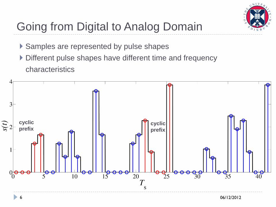
Samples are represented by pulse shapes
Different pulse shapes have different time and frequency
characteristics
Square and triangular pulse
shapes have infinite
bandwidth
Sinc function has the best
spectral characteristic, but
has an infinite impulse
response
Raised cosine (root-raised
cosine) filter is a good
practical filter.
cyclic
prefix
cyclic
prefix
06/12/2012 7
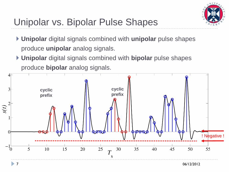
Unipolar vs. Bipolar Pulse Shapes
Unipolar digital signals combined with unipolar pulse shapes
produce unipolar analog signals.
Unipolar digital signals combined with bipolar pulse shapes
produce bipolar analog signals.
! Negative !
cyclic
prefix
cyclic
prefix
06/12/2012 8
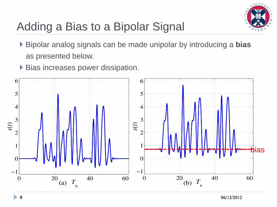
Adding a Bias to a Bipolar Signal
Bipolar analog signals can be made unipolar by introducing a bias
as presented below.
Bias increases power dissipation.
bias
06/12/2012 9
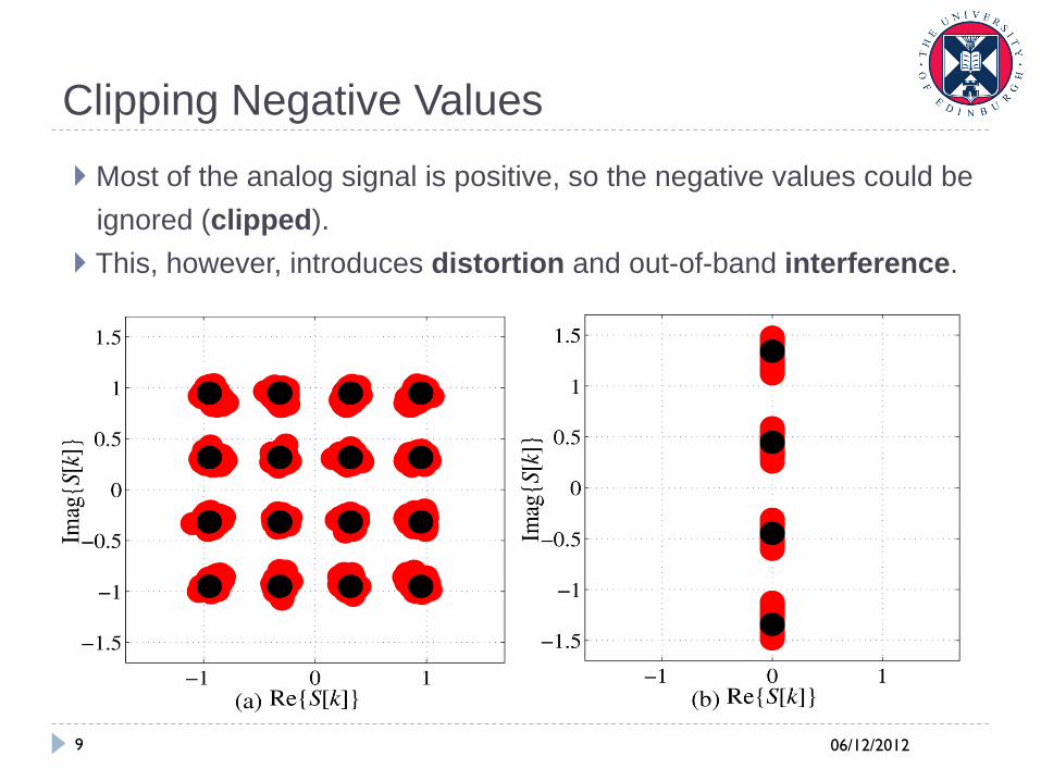
Clipping Negative Values
Most of the analog signal is positive, so the negative values could be
ignored (clipped).
This, however, introduces distortion and out-of-band interference.
06/12/2012 10
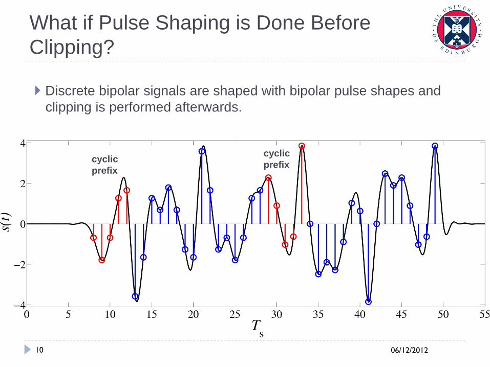
What if Pulse Shaping is Done Before
Clipping?
Discrete bipolar signals are shaped with bipolar pulse shapes and
clipping is performed afterwards.
cyclic
prefix
cyclic
prefix
06/12/2012 11
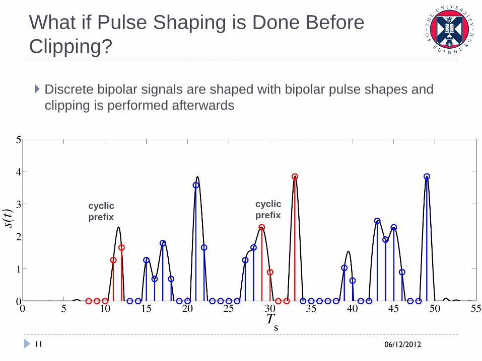
What if Pulse Shaping is Done Before
Clipping?
Discrete bipolar signals are shaped with bipolar pulse shapes and
clipping is performed afterwards
cyclic
prefix
cyclic
prefix
06/12/2012 12
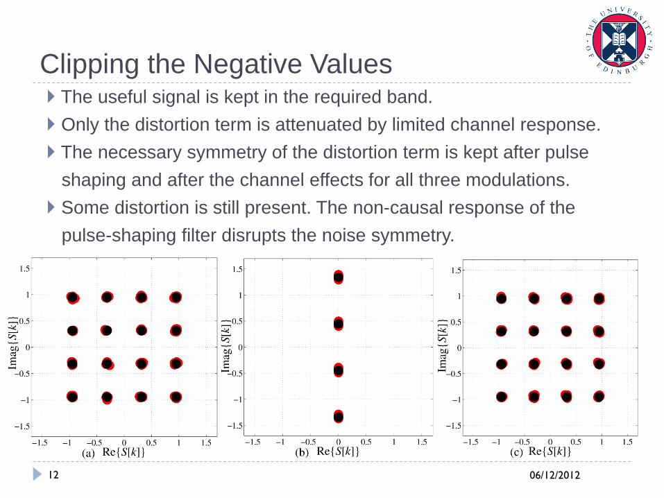
Clipping the Negative Values The useful signal is kept in the required band.
Only the distortion term is attenuated by limited channel response.
The necessary symmetry of the distortion term is kept after pulse
shaping and after the channel effects for all three modulations.
Some distortion is still present. The non-causal response of the
pulse-shaping filter disrupts the noise symmetry.
06/12/2012 13
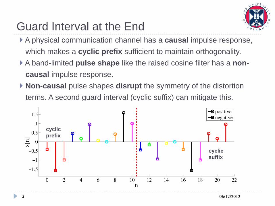
Guard Interval at the End A physical communication channel has a causal impulse response,
which makes a cyclic prefix sufficient to maintain orthogonality.
A band-limited pulse shape like the raised cosine filter has a non-
causal impulse response.
Non-causal pulse shapes disrupt the symmetry of the distortion
terms. A second guard interval (cyclic suffix) can mitigate this.
cyclic
prefix
cyclic
suffix
06/12/2012 14
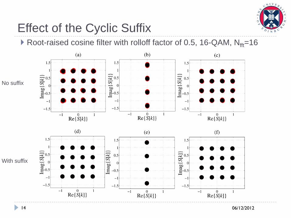
Effect of the Cyclic Suffix Root-raised cosine filter with rolloff factor of 0.5, 16-QAM, Nfft=16
No suffix
With suffix
06/12/2012 15
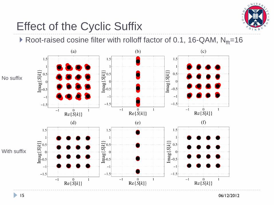
Effect of the Cyclic Suffix Root-raised cosine filter with rolloff factor of 0.1, 16-QAM, Nfft=16
No suffix
With suffix
06/12/2012 16
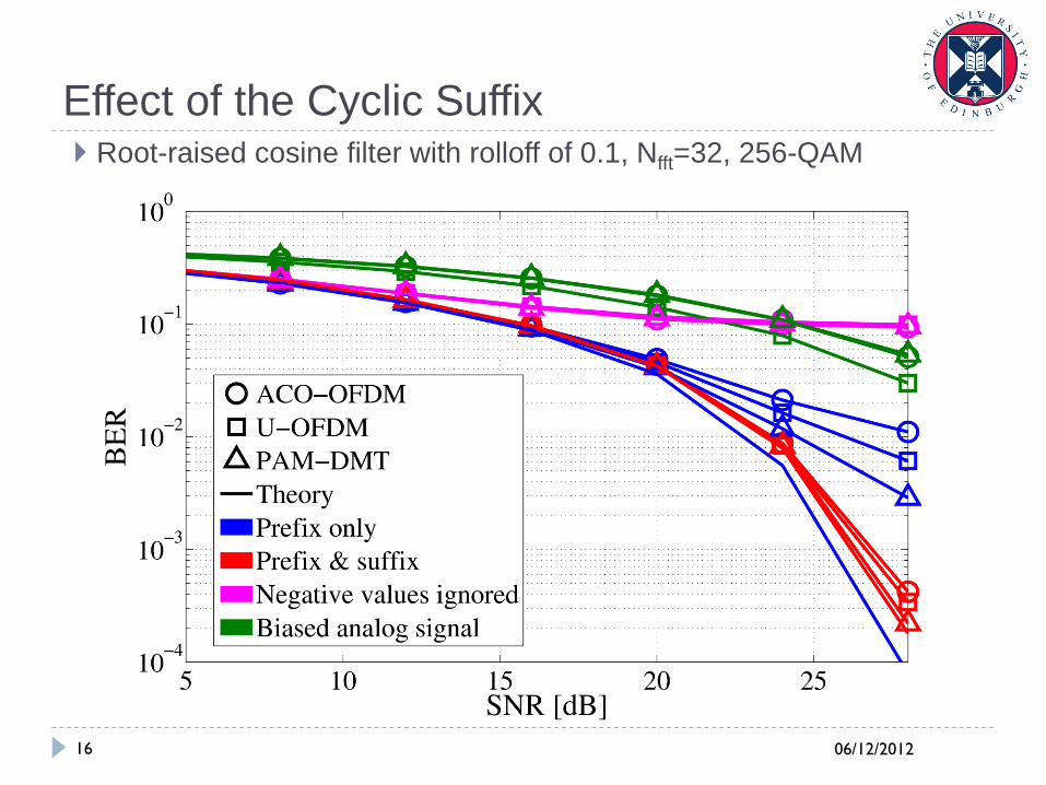
Effect of the Cyclic Suffix Root-raised cosine filter with rolloff of 0.1, Nfft=32, 256-QAM
06/12/2012 17
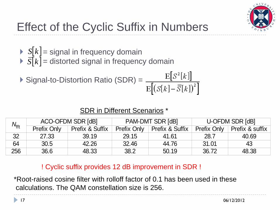
Effect of the Cyclic Suffix in Numbers
= signal in frequency domain
= distorted signal in frequency domain
Signal-to-Distortion Ratio (SDR) =
kS
kS
ACO-OFDM SDR [dB] PAM-DMT SDR [dB] U-OFDM SDR [dB]Prefix Only Prefix & Suffix Prefix Only Prefix & Suffix Prefix Only Prefix & suffix
32 27.33 39.19 29.15 41.61 28.7 40.6964 30.5 42.26 32.46 44.76 31.01 43256 36.6 48.33 38.2 50.19 36.72 48.38
Nfft
*Root-raised cosine filter with rolloff factor of 0.1 has been used in these
calculations. The QAM constellation size is 256.
SDR in Different Scenarios *
! Cyclic suffix provides 12 dB improvement in SDR !
06/12/2012 18
Conclusions
Discrete unipolar signals require unipolar pulse shapes
Bipolar pulse shaping can be applied as long as pulse shaping is
applied before clipping the negative values.
After pulse shaping, distortion terms still retain required
symmetry to stay orthogonal to the useful information.
Non-causal pulse shapes disrupt the symmetry of the distortion
terms. A second guard interval (cyclic suffix) can mitigate this.

06/12/2012 19
Thank you very much for the attention !
06/12/2012 20
Motivation
Demands for wireless data rates are growing exponentially. In 2015,
more than 6 Exabytes of data are expected to be sent globally.
RF spectrum is insufficient for growing demands. New physical
domains for Wireless Communications are desirable.
Optical wireless communication is a potential solution to the
emerging spectrum problem.
06/12/2012 21
Asymmetrically Clipped Optical OFDM
(ACO-OFDM)
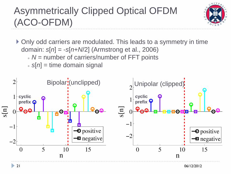
Only odd carriers are modulated. This leads to a symmetry in time
domain: s[n] = -s[n+N/2] (Armstrong et al., 2006)
● N = number of carriers/number of FFT points
● s[n] = time domain signal
Bipolar (unclipped)
Unipolar (clipped)
cyclic
prefix
cyclic
prefix
06/12/2012 22
ACO-OFDM Theory
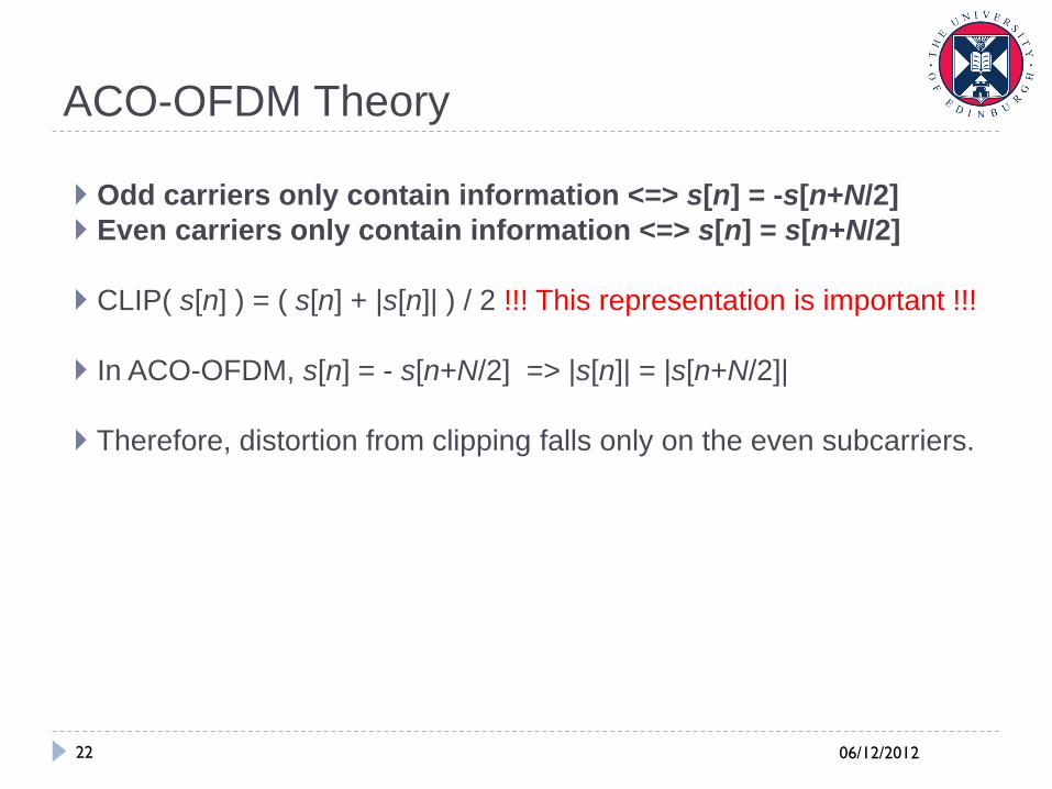
Odd carriers only contain information <=> s[n] = -s[n+N/2]
Even carriers only contain information <=> s[n] = s[n+N/2]
CLIP( s[n] ) = ( s[n] + |s[n]| ) / 2 !!! This representation is important !!!
In ACO-OFDM, s[n] = - s[n+N/2] => |s[n]| = |s[n+N/2]|
Therefore, distortion from clipping falls only on the even subcarriers.
06/12/2012 23
Pulse-amplitude-modulated Discrete
Multitone Modulation (PAM-DMT)
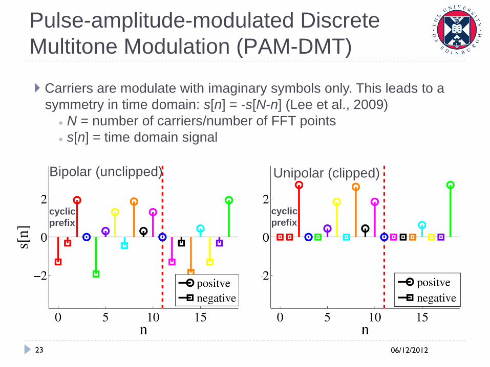
Carriers are modulate with imaginary symbols only. This leads to a
symmetry in time domain: s[n] = -s[N-n] (Lee et al., 2009)
● N = number of carriers/number of FFT points
● s[n] = time domain signal
Bipolar (unclipped)
Unipolar (clipped)
cyclic
prefix
cyclic
prefix
06/12/2012 24
PAM-DMT Theory
Carriers are modulated with imaginary symbols <=> s[n] = -s[N-n]
Carriers are modulated with real symbols <=> s[n] = s[N-n]
CLIP( s[n] ) = ( s[n] + |s[n]| ) / 2 !!! This representation is important !!!
In PAM-DMT, s[n] = - s[N-n] => |s[n]| = |s[N-n]|
Therefore, distortion from clipping falls only on the real values in
frequency domain.