Embed Size (px)
Citation preview

DIGITAL INDICATING CONTROLLER
BCx2INSTRUCTION MANUAL

2
PrefaceThank you for purchasing our digital indicating controller BCx2 (BCS2, BCR2, BCD2). This manual contains
instructions for the mounting, functions, operations and notes when operating the BCx2. To prevent accidents
arising from the misuse of this controller, please ensure the operator receives this manual.
Abbreviations used in this manual
Abbreviation Term
PV Process variable
SV Desired value
MV Manipulated variable
DV Deviation
OUT1 Control output OUT1
OUT2 Control output OUT2
AT Auto-tuning
Characters used in this manual
Indication
Number, / -1 0 1 2 3 4 5 6 7 8 9
Indication
Alphabet A B C D E F G H I J K L M
Indication
Alphabet N O P Q R S T U V W X Y Z
Notes• This instrument should be used in accordance with the specifications described in the manual.
If it is not used according to the specifications, it may malfunction or cause a fire.
• Be sure to follow the warnings, cautions and notices. If they are not observed, serious injury or malfunction
may occur.
• The contents of this instruction manual are subject to change without notice.
• Care has been taken to ensure that the contents of this instruction manual are correct, but if there are any
doubts, mistakes or questions, please inform our sales department.
• Measures must be taken to ensure that the operator cannot touch power terminals or other high voltage
sections.
• Any unauthorized transfer or copying of this document, in part or in whole, is prohibited.
• Shinko Technos Co., Ltd. is not liable for any damage or secondary damage(s) incurred as a result of using
this product, including any indirect damage.

3
Safety Precautions (Be sure to read these precautions before using our products.)
The safety precautions are classified into categories: “Warning” and “Caution”. Depending on circumstances,procedures indicated by Caution may result in serious consequences, so be sure to follow the directionsfor usage.
Warning
Warning• To prevent an electrical shock or fire, only Shinko or other qualified service personnel may handle theinner assembly.
• To prevent an electrical shock, fire or damage to the instrument, parts replacement may only beundertaken by Shinko or other qualified service personnel.
Safety Precautions• To ensure safe and correct use, thoroughly read and understand this manual before using this instrument.• This instrument is intended to be used for industrial machinery, machine tools and measuring equipment. Verify
correct usage after purpose-of-use consultation with our agency or main office. (Never use this instrument formedical purposes with which human lives are involved.)
• External protection devices such as protective equipment against excessive temperature rise, etc. must beinstalled, as malfunction of this product could result in serious damage to the system or injury to personnel.Proper periodic maintenance is also required.
• This instrument must be used under the conditions and environment described in this manual. Shinko TechnosCo., Ltd. does not accept liability for any injury, loss of life or damage occurring due to the instrument being usedunder conditions not otherwise stated in this manual.
Caution with respect to Export Trade Control OrdinanceTo avoid this instrument from being used as a component in, or as being utilized in the manufacture ofweapons of mass destruction (i.e. military applications, military equipment, etc.), please investigate the endusers and the final use of this instrument. In the case of resale, ensure that this instrument is not illegallyexported.
1. Installation Precautions
CautionThis instrument is intended to be used under the following environmental conditions(IEC61010-1): Overvoltage category , Pollution degree 2Ensure the mounting location corresponds to the following conditions:• A minimum of dust, and an absence of corrosive gases• No flammable, explosive gases• No mechanical vibrations or shocks• No exposure to direct sunlight, an ambient temperature of -10 to 55 (14 to 131 ) that does notchange rapidly, and no icing
• An ambient non-condensing humidity of 35 to 85%RH• No large capacity electromagnetic switches or cables through which large current is flowing• No water, oil or chemicals or where the vapors of these substances can come into direct contact with
the unit• Take note that the ambient temperature of this unit – not the ambient temperature of the control panel –must not exceed 55 (131 ) if mounted through the face of a control panel, otherwise the life ofelectronic components (especially electrolytic capacitors) may be shortened.
Note • Avoid setting this instrument directly on or near flammable material even though the caseof this instrument is made of flame-resistant resin.
Caution
Procedures which may lead to dangerous conditions and cause death or seriousinjury, if not carried out properly.
Procedures which may lead to dangerous conditions and cause superficial tomedium injury or physical damage or may degrade or damage the product, if notcarried out properly.

4
2. Wiring Precautions
Caution• Do not leave wire remnants in the instrument, as they could cause a fire or malfunction.
• Use the solderless terminal with an insulation sleeve in which the M3 screw fits when wiring the
instrument.
• The terminal block of this instrument is designed to be wired from the left side. The lead wire must be
inserted from the left side of the terminal, and fastened with the terminal screw.
• Tighten the terminal screw using the specified torque. If excessive force is applied to the screw when
tightening, the terminal screw or case may be damaged.
• Do not pull or bend the lead wire on the terminal side when wiring or after wiring, as it could cause
malfunction.
• When using a terminal cover for the BCS2, pass terminal wires numbered 7 to 12 into the holes of the
terminal cover.
• This instrument does not have a built-in power switch, circuit breaker and fuse.
It is necessary to install a power switch, circuit breaker and fuse near the controller.
(Recommended fuse: Time-lag fuse, rated voltage 250 V AC, rated current 2 A)
• For a 24 V AC/DC power source, do not confuse polarity when using direct current (DC).
• Do not apply a commercial power source to the sensor which is connected to the input terminal nor
allow the power source to come into contact with the sensor.
• Use a thermocouple and compensating lead wire according to the sensor input specifications of this
controller.
• Use the 3-wire RTD according to the sensor input specifications of this controller.
• For DC voltage input, (+) side input terminal number of 0 to 5 V DC, 1 to 5 V DC, 0 to 10 V DC differs
from that of 0 to 1 V DC.
Model Terminal Number
BCS2 9 : (+) side of 0 to 5 V DC, 1 to 5 V DC, 0 to 10 V DC10 : (+) side of 0 to 1 V DC
BCR2, BCD2 21 : (+) side of 0 to 5 V DC, 1 to 5 V DC, 0 to 10 V DC22 : (+) side of 0 to 1 V DC
• When using a relay contact output type, externally use a relay according to the capacity of the load to
protect the built-in relay contact.
• When wiring, keep input wires (thermocouple, RTD, etc.) away from controller
AC power sources or load wires.
3. Operation and Maintenance Precautions
Caution• It is recommended that AT be performed on the trial run.
• Do not touch live terminals. This may cause electrical shock or problems in operation.
• Turn the power supply to the instrument OFF when retightening the terminal or cleaning.
Working on or touching the terminal with the power switched ON may result in severe injury or death
due to electrical shock.
• Use a soft, dry cloth when cleaning the instrument.
(Alcohol based substances may tarnish or deface the unit.)
• As the display section is vulnerable, do not strike or scratch it with a hard object or put pressure on it.

5
Contents
Page
1. Model
1.1 Model ------------------------------------------------------------------------------------- 7
1.2 How to Read the Model Label ------------------------------------------------------ 8
2. Names and Functions of Sections ------------------------------------------------- 9
3. Mounting to the Control Panel
3.1 External Dimensions (Scale: mm) ----------------------------------------------- 12
3.2 Panel Cutout (Scale: mm) --------------------------------------------------------- 13
3.3 CT (Current Transformer) External Dimensions (Scale: mm) ------------- 14
3.4 Mounting to, and Removal from, the Control Panel
3.4.1 How to Mount the Unit ---------------------------------------------------------- 15
3.4.2 How to Remove the Mounting Frame and Unit ------------------------- 17
4. Wiring
4.1 Terminal Arrangement --------------------------------------------------------------- 19
4.2 Lead Wire Solderless Terminal ---------------------------------------------------- 20
4.3 Terminal Cover ------------------------------------------------------------------------ 21
4.4 Wiring
4.4.1 Power Supply ------------------------------------------------------------------- 22
4.4.2 Control Output OUT1, OUT2 ----------------------------------------------- 22
4.4.3 Input ------------------------------------------------------------------------------- 23
4.4.4 Event Output 1, Event Output 2 -------------------------------------------- 24
4.4.5 Insulated Power Output ------------------------------------------------------ 24
4.4.6 CT Input -------------------------------------------------------------------------- 25
4.4.7 Serial Communication -------------------------------------------------------- 27
4.4.8 Event Input ---------------------------------------------------------------------- 29
4.4.9 External Setting Input --------------------------------------------------------- 29
4.4.10 Transmission Output -------------------------------------------------------- 29
5. Outline of Key Operation and Each Mode
5.1 Key Operation ------------------------------------------------------------------------- 30
5.2 Modes ----------------------------------------------------------------------------------- 32
5.3 Basic Operation after Power-ON ------------------------------------------------- 33
6. Initial Setting ----------------------------------------------------------------------------- 37
6.1 Example of Initial Setting ----------------------------------------------------------- 38
6.2 Initial Setting Mode ------------------------------------------------------------------ 40
7. Settings
7.1 Main Setting Mode ------------------------------------------------------------------- 53
7.2 Sub Setting Mode -------------------------------------------------------------------- 58
7.3 Engineering Mode 1 ----------------------------------------------------------------- 64
7.4 Engineering Mode 2 ----------------------------------------------------------------- 79
8. Operation and Settings of Standard Functions
8.1 Selecting an input type -------------------------------------------------------------- 80
8.2 Selecting PID Control or ON/OFF Control ------------------------------------- 81
8.3 Selecting Direct/Reverse Action -------------------------------------------------- 82
8.4 Performing Fixed Value Control -------------------------------------------------- 83
8.5 Setting PID Constants (by Performing AT) ------------------------------------ 84
8.6 Performing Auto-reset --------------------------------------------------------------- 87
8.7 Performing Program Control ------------------------------------------------------ 88
8.8 Event Output EV1 Allocation ------------------------------------------------------ 95
8.9 Indicating MV, Remaining Time (Program Control) -------------------------- 97
8.10 Items to be Initialized by Changing Settings -------------------------------- 98

6
9. Attached Function
9.1 Input Value Correction -------------------------------------------------------------- 99
9.2 Set Value Lock ----------------------------------------------------------------------- 101
9.3 Control Output OFF Function ---------------------------------------------------- 102
9.4 Switching Auto/Manual Control (Auto/Manual Control Function) ------- 103
9.5 Using as a Converter --------------------------------------------------------------- 104
9.5.1 Selecting Converter Function ---------------------------------------------- 105
9.5.2 Fine Adjustment of Converter Output (4 to 20 mA DC) -------------- 106
9.5.3 Converter Setting Example ------------------------------------------------ 107
9.6 Clearing Data ------------------------------------------------------------------------ 108
10. Action Explanation
10.1 OUT1 Action ----------------------------------------------------------------------- 109
10.2 OUT1 ON/OFF Control Action ------------------------------------------------- 109
10.3 Heater Burnout Alarm Action --------------------------------------------------- 110
10.4 Alarm Action ------------------------------------------------------------------------ 111
10.5 OUT2 (Heating/Cooling Control) Action ------------------------------------- 113
10.6 OUT2 (Heating/Cooling Control) Action (When Setting Dead Band) - 114
10.7 OUT2 (Heating/Cooling Control) Action (When Setting Overlap Band)- 115
11. Specifications
11.1 Standard Specifications ---------------------------------------------------------- 116
11.2 Optional Specifications ----------------------------------------------------------- 127
12. Troubleshooting
12.1 Indication ---------------------------------------------------------------------------- 129
12.2 Key Operation ---------------------------------------------------------------------- 131
12.3 Control ------------------------------------------------------------------------------- 132
13. Character Table
13.1 Error Code -------------------------------------------------------------------------- 133
13.2 Run Mode --------------------------------------------------------------------------- 133
13.3 Monitor Mode ----------------------------------------------------------------------- 133
13.4 Initial Setting Mode --------------------------------------------------------------- 134
13.5 Main Setting Mode ---------------------------------------------------------------- 140
13.6 Sub Setting Mode ----------------------------------------------------------------- 142
13.7 Engineering Mode 1 -------------------------------------------------------------- 144
13.8 Engineering Mode 2 -------------------------------------------------------------- 150
14 Key Operation Flowchart ------------------------------------------------------------ 151

7
1. Model1.1 Model
B C 2 -
BCS2 48 x 48 x 68 mm (W x H x D) (Depth of control panel interior: 60)
BCR2 48 x 96 x 68 mm (W x H x D) (Depth of control panel interior: 60)Size
BCD2 96 x 96 x 68 mm (W x H x D) (Depth of control panel interior: 60)
R Relay contact: 1a
S Non-contact voltage (for SSR drive) 12 V DC 15%Control output
OUT1A Direct current: 4 to 20 mA DC
0 100 to 240 V AC (Standard)Power supply
voltage 1 24 V AC/DC
Input 0 Multi-range (*1)
0 No Option 1 needed.
1 EV2 Event output EV2 (*3)
2 DS Heating/Cooling control output OUT2, Non-contact voltage
3 DA Heating/Cooling control output OUT2, Direct current
4 P24 Insulated power output
5 EV2+DR(*4) Event output EV2 (*3) + Heating/Cooling control
output OUT2, Relay contact
6 EV2+DS(*4) Event output EV2 (*3) + Heating/Cooling control
output OUT2, Non-contact voltage
Option 1 (*2)
(Choose only one option.)
7 EV2+DA(*4) Event output EV2 (*3) + Heating/Cooling control
output OUT2, Direct current
0 No Option 2 needed.
1 C5W (20A) Event input (2 points) (*5) + Serial communication +
Heater burnout alarm (20A) (*6)
2 C5W (100A) Event input (2 points) (*5) + Serial communication +
Heater burnout alarm (100A) (*6)
3 EIW (20A) Event input (2 points) +
Heater burnout alarm (20A) (*6)
4 EIW (100A) Event input (2 points) +
Heater burnout alarm (100A) (*6)
5 EIT Event input (2 points) (*7)+
External setting input + Transmission output
6 C5 Serial communication
7 W (20A) Heater burnout alarm (20 A) (*6)
8 W (100A) Heater burnout alarm (100 A) (*6)
Option 2 (*2)
(Choose only one option.)
9 EI Event input (2 points)
(*1) Thermocouple, RTD, Direct current and DC voltage can be selected by keypad.
(*2) Only one option can be selected from Option 1 and Option 2 respectively.
(*3) Event output EV1 is standard.
The following outputs can be selected in [Event output EV1/EV2 allocation] by keypad:
Alarm output (12 alarm types and No alarm action), Heater burnout alarm output, Loop break alarm output,
Time signal output, Output during AT, Pattern end output, Output by communication command, Heating/Cooling
control output OUT2 (for EV2 option only).
For Event output EV1/EV2, Heater burnout alarm output and Output by communication command are available
when C5W, EIW, C5 or W option is ordered.
(*4) When EV2+D option and EIT option are added simultaneously, Transmission output terminals become EV2 output
terminals, so Transmission output is disabled. For the BCS2, EV2+D cannot be selected.
(*5) For the BCS2, Event input (2 points) is not available.
(*6) For direct current output type, Heater burnout alarm does not work.
(*7) For the BCS2, 1 point of Event input is available.

8
1.2 How to Read the Model Label
The model label is attached to the right side of the case.
BCS2 BCR2, BCD2
(e.g.) BCS2R00-12 (e.g.) BCD2R00-12
(Fig. 1.2-1) (Fig. 1.2-2)
No. Description Example
(1) Terminal arrangement BCS2R00-12, BCD2R00-12 (*1)
(2) Model BCS2R00-12, BCD2R00-12
(3) Option EV2 (Event output EV2)
C5W(100A) [Serial communication + Heater burnout
alarm (100 A)] (*2)
(4) Input MULTI-RANGE (Multi-range input)
(5) Control output, Event output O1: 3 A 250 V AC (Control output OUT1)
EV1: 3 A 250 V AC (Event output EV1)
EV2: 3 A 250 V AC (Event output EV2)
(6) Power supply voltage,
Power consumption
100 to 240 V AC 50/60 Hz,
11 VA
(7) Serial number No. 145F05000(*1) Terminal arrangement diagram differs depending on the model.
(*2) For Heater burnout alarm output (C5W, EIW, W options), CT rated current is entered in bracket ( ).
(7)
(2)
(3)
(4)
(5)
(6)
(7)
(2)
(3)
(4)
(5)
(6)
(1)
(1)

9
2. Name and Functions of SectionsBCS2
(Fig. 2-1)
BCR2
(Fig. 2-2)
(1)
(2)
(4)
(5)
(6)
(8)
(7)
(9)
(1)
(2)
(4)
(5)
(6)
(8)
(9)
(3)
(7)

10
BCD2
(Fig. 2-3)
Display
No. Name Description
(1) PV Display Indicates PV.
Indicates setting characters in each setting mode.
Indicates SV.
Indicates set data in each setting mode.
In Monitor mode, indicated contents differ depending on the model as
follows.
Model Indicated Contents
BCS2 Indicates MV, Remaining time (Program control), Step
number (Program control) or Set value memory number
(Fixed value control).
(2) SV Display
BCR2, BCD2 Indicates MV or Remaining time (Program control).
(3) MEMO/STEP
Display
Indicates Set value memory number (Fixed value control) or Step number
(Program control). (For BCR2, BCD2)
(1)
(2)
(4)
(5)
(6)
(8)
(9)
(3)
(7)
11
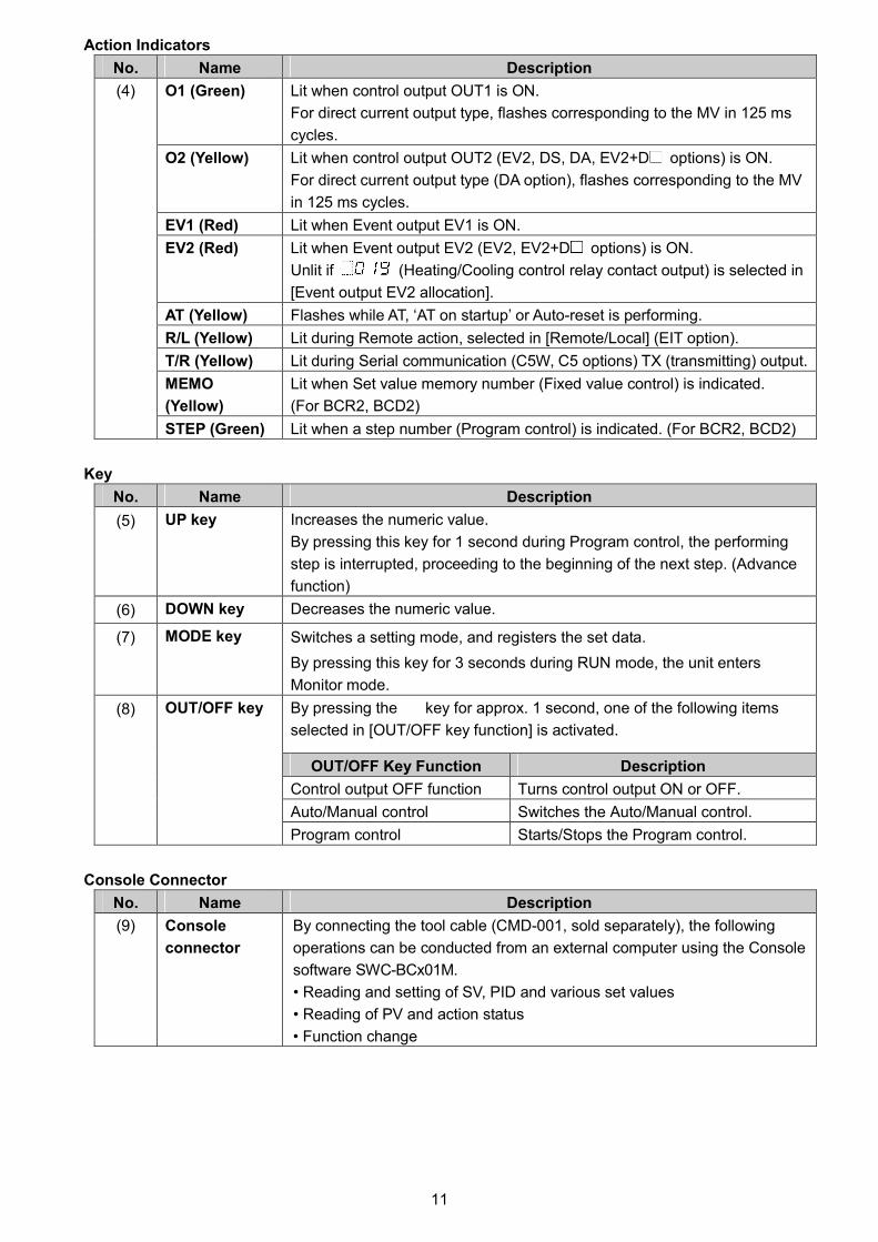
Action Indicators
No. Name Description
O1 (Green) Lit when control output OUT1 is ON.
For direct current output type, flashes corresponding to the MV in 125 ms
cycles.
O2 (Yellow) Lit when control output OUT2 (EV2, DS, DA, EV2+D options) is ON.
For direct current output type (DA option), flashes corresponding to the MV
in 125 ms cycles.
EV1 (Red) Lit when Event output EV1 is ON.
EV2 (Red) Lit when Event output EV2 (EV2, EV2+D options) is ON.
Unlit if (Heating/Cooling control relay contact output) is selected in
[Event output EV2 allocation].
AT (Yellow) Flashes while AT, ‘AT on startup’ or Auto-reset is performing.
R/L (Yellow) Lit during Remote action, selected in [Remote/Local] (EIT option).
T/R (Yellow) Lit during Serial communication (C5W, C5 options) TX (transmitting) output.
MEMO
(Yellow)
Lit when Set value memory number (Fixed value control) is indicated.
(For BCR2, BCD2)
(4)
STEP (Green) Lit when a step number (Program control) is indicated. (For BCR2, BCD2)
Key
No. Name Description
(5) UP key Increases the numeric value.
By pressing this key for 1 second during Program control, the performing
step is interrupted, proceeding to the beginning of the next step. (Advance
function)
(6) DOWN key Decreases the numeric value.
(7) MODE key Switches a setting mode, and registers the set data.
By pressing this key for 3 seconds during RUN mode, the unit enters
Monitor mode.
By pressing the key for approx. 1 second, one of the following items
selected in [OUT/OFF key function] is activated.
OUT/OFF Key Function Description
Control output OFF function Turns control output ON or OFF.
Auto/Manual control Switches the Auto/Manual control.
(8) OUT/OFF key
Program control Starts/Stops the Program control.
Console Connector
No. Name Description
(9) Console
connector
By connecting the tool cable (CMD-001, sold separately), the following
operations can be conducted from an external computer using the Console
software SWC-BCx01M.
• Reading and setting of SV, PID and various set values
• Reading of PV and action status
• Function change

12
3. Mounting to the Control Panel3.1 External Dimensions (Scale: mm)
BCS2
(Fig. 3.1-1)
BCR2
(Fig. 3.1-2)
(*) When the terminal cover is used.
Gasket
Mounting frame
Terminal cover (sold separately)
Gasket Terminal cover (sold separately)
(*) When the terminal cover is used.
Screw type mounting bracket
Gasket Terminal cover (sold separately)
Screw type mounting bracket

13
BCD2
(Fig. 3.1-3)
3.2 Panel Cutout (Scale: mm)
CautionIf lateral close mounting is used for the controller, IP66 specification (Drip-proof/Dust-proof)
may be compromised, and all warranties will be invalidated.
BCS2
Lateral close mounting
n: Number of units mounted
(Fig. 3.2-1)
Gasket Terminal cover (sold separately)
Screw type mounting bracket
(*) When terminal covers are used.

14
BCR2
Lateral close mounting
n: Number of units mounted
(Fig. 3.2-2)
BCD2
Lateral close mounting
n: Number of units mounted
(Fig. 3.2-3)
3.3 CT (Current Transformer) External Dimensions (Scale: mm)
CTL-6S (for 20 A) CTL-12-S36-10L1U (for 100 A)
(Fig. 3.3-1)
13
0
92+
0.8 0
45+0.50
n×48-3 +0.50
92+
0.8 0
□92+0.80
130
n×96-3 +0.50
92+
0.8
0

15
3.4 Mounting to, and Removal from, the Control Panel
CautionAs the mounting frame of the BCS2 is made of resin, do not use excessive force while
tightening screws, or the mounting frame could be damaged.
Tighten screws with one rotation upon the screw tips touching the panel.
The torque is 0.05 to 0.06 N•m.
For the BCR2, BCD2, the torque should be 0.1 N•m.
3.4.1 How to Mount the Unit
BCS2
Mount the controller vertically to the flat, rigid panel to ensure it adheres to the Drip-proof/Dust-proof
specification (IP66).
If the lateral close mounting is used for the controller, IP66 specification (Drip-proof/Dust-proof) may
be compromised, and all warranties will be invalidated.
Mountable panel thickness: 1 to 5 mm
(1) Insert the controller from the front side of the control panel. (Fig. 3.4.1-1)
If the Drip-proof/Dust-proof specification (IP66) is not necessary, the gasket may be removed
(please keep in mind the warranty is void if gasket is removed).
(2) Insert the mounting frame until it comes into contact with the panel, and fasten with screws.
Tighten screws with one rotation upon the screw tips touching the panel. (Fig. 3.4.1-2)
The torque is 0.05 to 0.06 N•m.
(Fig. 3.4.1-1) (Fig. 3.4.1-2)
Mounting frame
Gasket

16
BCR2, BCD2
Mount the controller vertically to the flat, rigid panel to ensure it adheres to the Drip-proof/Dust-proof
specification (IP66).
If the lateral close mounting is used for the controller, IP66 specification (Drip-proof/Dust-proof) may
be compromised, and all warranties will be invalidated.
Mountable panel thickness: 1 to 7 mm
(1) Insert the controller from the front side of the control panel. (Fig. 3.4.1-3)
If the Drip-proof/Dust-proof specification (IP66) is not necessary, the gasket may be removed.
(Please keep in mind the warranty is void if gasket is removed).
(Fig. 3.4.1-3)
(2) Attach the mounting brackets by the holes at the top and bottom of the case, and secure the
controller in place with the screws.
The torque is 0.1 N•m.
(Fig. 3.4.1-4)
Screw typemounting bracket
Gasket

17
3.4.2 How to Remove the Mounting Frame and Unit
BCS2 (Fig. 3.4.2-1)
(1) Turn the power to the unit OFF, and disconnect all wires before removing the mounting frame.
(2) Insert a flat blade screwdriver between the mounting frame and unit ( 1 ).
(3) Slowly push the frame upward using the screwdriver ( 2 ), while pushing the unit toward the
panel ( 3 ).
(4) Repeat step (2) and slowly push the frame downward using the screwdriver for the other side.
The frame can be removed little by little by repeating these steps.
(Fig. 3.4.2-1)
BCR2, BCD2
(1) Turn the power to the unit OFF, and disconnect all wires before removing the unit.
(2) Loosen the screws of the mounting brackets, and remove the mounting brackets.
(3) Pull the unit out from the front of the control panel.
①
②
③

18
4. Wiring
WarningTurn the power supply to the instrument off before wiring or checking.
Working on or touching the terminal with the power switched on may result in severe injury
or death due to electrical shock.
Caution• Do not leave wire remnants in the instrument, as they could cause a fire or malfunction.
• Use the solderless terminal with an insulation sleeve in which the M3 screw fits when wiring the
instrument.
• The terminal block of this instrument is designed to be wired from the left side. The lead wire must be
inserted from the left side of the terminal, and fastened with the terminal screw.
• Tighten the terminal screw using the specified torque. If excessive force is applied to the screw when
tightening, the terminal screw or case may be damaged.
• Do not pull or bend the lead wire on the terminal side when wiring or after wiring, as it could cause
malfunction.
• When using a terminal cover for the BCS2, pass terminal wires numbered 7 to 12 into the holes of the
terminal cover.
• This instrument does not have a built-in power switch, circuit breaker and fuse.
It is necessary to install a power switch, circuit breaker and fuse near the controller.
(Recommended fuse: Time-lag fuse, rated voltage 250 V AC, rated current 2 A)
• For a 24 V AC/DC power source, do not confuse polarity when using direct current (DC).
• Do not apply a commercial power source to the sensor which is connected to the input terminal nor
allow the power source to come into contact with the sensor.
• Use a thermocouple and compensating lead wire according to the sensor input specifications of this
controller.
• Use the 3-wire RTD according to the sensor input specifications of this controller.
• For DC voltage input, (+) side input terminal number of 0 to 5 V DC, 1 to 5 V DC, 0 to 10 V DC differs
from that of 0 to 1 V DC.
Model Terminal Number
BCS2 9 : (+) side of 0 to 5 V DC, 1 to 5 V DC, 0 to 10 V DC10 : (+) side of 0 to 1 V DC
BCR2, BCD2 21 : (+) side of 0 to 5 V DC, 1 to 5 V DC, 0 to 10 V DC22 : (+) side of 0 to 1 V DC
• When using a relay contact output type, externally use a relay according to the capacity of the load to
protect the built-in relay contact.
• When wiring, keep input wires (thermocouple, RTD, etc.) away from AC sources or load wires.

19
4.1 Terminal Arrangement
Terminal arrangement of the BCS2, BCR2, BCD2 differs depending on the options as follows.
BCS2
(Fig. 4.1-1)
BCR2, BCD2
(Fig. 4.1-2)

20
Terminal Description
POWER SUPPLY 100 to 240 V AC or 24 V AC/DC
For a 24 V AC/DC power source, do not confuse polarity when using
direct current (DC).
EV1 Event output EV1
EV2 Event output EV2 (EV2, EV2+D options)
O2 Control output OUT2 (EV2, DS, DA, EV2+D options)
P24 24 V DC insulated power output (P24 option)
O1 Control output OUT1
RTD RTD input
TC Thermocouple input
DC Direct current, DC voltage inputs
For DC voltage input, (+) side input terminal number of 0 to 5 V DC, 1 to
5 V DC, 0 to 10 V DC differs from that of 0 to 1 V DC.
Model Terminal Number
BCS2 9 : + side of 0 to 5 V DC, 1 to 5 V DC, 0 to 10 V DC10 : + side of 0 to 1 V DC
BCR2, BCD2 21 : + side of 0 to 5 V DC, 1 to 5 V DC, 0 to 10 V DC22 : + side of 0 to 1 V DC
CT1 CT input 1 (C5W, EIW, W options)
CT2 CT input 2 (C5W, EIW, W options)
RS-485 Serial communication RS-485 (C5W, C5 options)
EVENT INPUT Event input DI1 (BCS2: EIW, EIT, EI options,
BCR2/BCD2: C5W, EIW, EIT, EI options)
Event input DI2 (BCS2: EIW, EI options,
BCR2/BCD2: C5W, EIW, EIT, EI options)
EXT CONT External setting input (EIT option)
TRANSMIT OUTPUT Transmission output (EIT option) or Event output EV2 (EV2+D option)
BCR2, BCD2: If EV2+D option and EIT option are added simultaneously,
Transmission output terminals become EV2 output terminals, so Transmission
output will be disabled.
4.2 Lead Wire Solderless Terminal
Use a solderless terminal with an insulation sleeve in which an M3 screw fits as shown below.
The torque should be 0.63 N•m.
Solderless
TerminalManufacturer Model
Tightening
Torque
Nichifu Terminal Industries Co., Ltd. TMEV1.25Y-3Y-type
Japan Solderless Terminal MFG Co., Ltd. VD1.25-B3A
Nichifu Terminal Industries Co., Ltd. TMEV1.25-3Ring-type
Japan Solderless Terminal MFG Co., Ltd. V1.25-3
0.63 N•m
(Fig. 4.2-1)
5.8
mm
ma
x.
5.8
mm
ma
x.3.2 mm 3.2 mm

21
4.3 Terminal CoverBCS2
When using a terminal cover (sold separately), make sure the longer side is on the back right sideof the case.Pass the wires from terminals 7 to 12 into the holes of the terminal cover.
Mount the longer side ofthe cover to the back right.
(Fig. 4.3-1)BCR2
When using a terminal cover (sold separately), make sure the longer side is on the back right sideof the case.Pass the wires from terminals 13 to 24 through the left side of the terminal cover.
(Fig. 4.3-2) (Fig. 4.3-3)
BCD2
When using terminal covers (sold separately), make sure the longer side is on the back right and leftsides of the case.Pass the wires from terminals 13 to 24 through between covers.
(Fig. 4.3-4) (Fig. 4.3-5)
2 terminal covers
Mount the longer side of thecover to the back right andleft.
Top of BCD2
Terminal cover
Terminal coverTop of BCR2
Mount the longer side of thecover to the back right.

22
4.4 Wiring
For the terminal arrangement, refer to Section ‘4.1 Terminal Arrangement’ (p.19).
4.4.1 Power Supply
Power supply voltage is 100 to 240 V AC or 24 V AC/DC.
For a 24 V AC/DC power source, ensure polarity is correct when using direct current (DC).
BCS2 BCR2, BCD2
4.4.2 Control Output OUT1, OUT2
When EV2, DS, DA or EV2+D option is ordered, control output OUT2 is available.
Specifications of Control output OUT1, OUT2 are shown below.
Relay contact 1a
Control capacity: 3 A 250 V AC (resistive load),
1 A 250 V AC (inductive load cos =0.4)
Electrical life: 100,000 cycles
Minimum applicable load: 10 mA 5 V DC
Non-contact voltage
(for SSR drive)
12 V DC 15%
Max. 40 mA (short circuit protected)
Direct current 4 to 20 mA DC
Load resistance: Max. 550
BCS2 BCR2, BCD2
Relay contactNon-contact voltage,
Direct currentRelay contact
Non-contact voltage,
Direct current
Number of Shinko SSR units when connected in parallel (for Non-contact voltage output):
• SA-400 series: 5 units
• SA-500 series: 2 units

23
4.4.3 Input
Each input wiring is shown below.
For DC voltage input, (+) side input terminal number of 0 to 5 V DC, 1 to 5 V DC, 0 to 10 V DC
differs from that of 0 to 1 V DC.
BCS2
Thermocouple RTD
Direct current,
DC voltage
(0 to 1 V)
DC voltage
(0 to 5 V,
1 to 5 V,
0 to 10 V)
BCR2, BCD2
Thermocouple RTD
Direct current,
DC voltage
(0 to 1 V)
DC voltage
(0 to 5 V,
1 to 5 V,
0 to 10 V)

24
4.4.4 Event Output 1, Event Output 2
Event output EV1 is a standard feature.
If EV2 or EV2+D option is ordered, Event output EV2 is available.
Specifications of Event output 1 and Event output 2 are shown below.
Relay contact 1a
Control capacity: 3 A 250 V AC (resistive load)
1 A 250 V AC (inductive load cos =0.4)
Electrical life: 100,000 cycles
Minimum applicable load: 10 mA 5 V DC
BCS2 BCR2, BCD2
For EV2 option For EV2+D option
4.4.5 Insulated Power Output
If P24 option is ordered, the Insulated power output is available.
Specifications of Insulated power output are shown below.
Output voltage 24 3 V DC (at load current 30 mA DC)
Ripple voltage Within 200 mV DC (at load current 30 mA DC)
Max load current 30 mA DC
BCS2 BCR2, BCD2

25
4.4.6 CT Input
CT input is available when Heater burnout alarm (C5W, EIW, W options) is ordered.
Cannot be used for detecting heater current under phase control.
BCS2 BCR2, BCD2
Use the CT (current transformer) provided, and pass one lead wire of the heater circuit
into the hole of the CT. (Fig. 4.4.6-1)
When wiring, keep the CT wire away from AC sources or load wires to avoid the external
interference.
BCS2
(Fig. 4.4.6-1)
If using 3-phase, pass any 2 lead wires of R, S, T into the CT, and connect them to
CT1 ( 13 - 14 ) and CT2 ( 14 - 15 ) terminals. (Fig. 4.4.6-2)
(Fig. 4.4.6-2)
CT1 input terminals
Power supply
CT
Heater
13
14
Power supply
CT1Heater
13
14
15
R
S
TCT2
CT1 input terminals
CT2 input terminals

26
BCR2, BCD2
(Fig. 4.4.6-3)
When using 3-phase, pass any 2 lead wires of R, S, T into the CT, and connect them to
CT1 ( 1 - 2 ) and CT2 ( 2 - 3 ) terminals. (Fig. 4.4.6-4)
(Fig. 4.4.6-4)
CT1 input terminals
Power supply
CT
Heater
1
2
Power supply
CT1Heater
1
2
3
R
S
TCT2
CT1 input terminals
CT2 input terminals
27
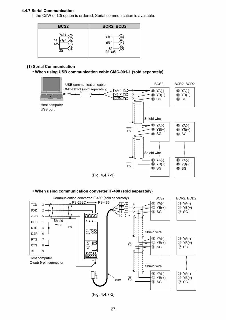
4.4.7 Serial CommunicationIf the C5W or C5 option is ordered, Serial communication is available.
BCS2 BCR2, BCD2
(1) Serial Communication
• When using USB communication cable CMC-001-1 (sold separately)
(Fig. 4.4.7-1)
• When using communication converter IF-400 (sold separately)
(Fig. 4.4.7-2)
RXD
TXD
DCD
DTR
DSR
RTS
CTS
2
3
5
1
4
6
7
8
GND
RI 9
CDM
FG
FG
FG
⑯ YA(-)⑰ YB(+)⑱ SG
⑯ YA(-)⑰ YB(+)⑱ SG
Shieldwire
4316
Host computer
D-sub 9-pin connector
⑯ YA(-)⑰ YB(+)⑱ SG
Shield wire
Shield wire
Communication converter IF-400 (sold separately)
RS-232C RS-485BCS2 BCR2, BCD2
⑩ YA(-)⑪ YB(+)⑫ SG
⑩ YA(-)⑪ YB(+)⑫ SG
⑩ YA(-)⑪ YB(+)⑫ SG
FG
FG
USB communication cable
CMC-001-1 (sold separately)
Host computer
USB port
⑯ YA(-)⑰ YB(+)⑱ SG
⑯ YA(-)⑰ YB(+)⑱ SG
⑯ YA(-)⑰ YB(+)⑱ SG
Shield wire
Shield wire
YA(-)
YB(+)
COM
BCS2 BCR2, BCD2
⑩ YA(-)⑪ YB(+)⑫ SG
⑩ YA(-)⑪ YB(+)⑫ SG
⑩ YA(-)⑪ YB(+)⑫ SG

28
(2) Set value digital transmission
By connecting to Shinko programmable controllers [PC-900 or PCD-33A with the SVTC (Set value
digital transmission) option], digital SV via the SVTC command can be received from programmable
controllers.
Wiring
For the PC-900, connect YA (-) to YA (-), YB (+) to YB (+), COM (PC-900) to SG (BCx2) terminal
respectively.
For the PCD-33A, connect YA (-) to YA (-), YB (+) to YB (+), SG to SG terminal respectively.
Up to 31 units of the BCS2 or BCR2 or BCD2 can be connected.
The following shows a connection example of PCD-33A and BCS2, BCR2, BCD2. (Fig. 4.4.7-3)
Wiring example of PCD-33A and BCx2
(Fig. 4.4.7-3)
Shield wire
Connect only one end of the shield to the FG terminal to avoid a ground loop. If both ends of theshield wire are connected to the FG terminal, the circuit will be closed, resulting in a ground loop. Thismay cause noise. Be sure to ground the FG terminal.
Recommended cable: OTSC-VB 2PX0.5SQ (made by Onamba Co., Ltd.) or equivalent (Use a twisted
pair cable.)
FG
FG
FG
YA(-) ⑪YB(+) ⑭
SG ⑰
Shieldwire
Shield wire
Shield wire
PCD-33A BCS2
⑯ YA(-)⑰ YB(+)⑱ SG
BCR2, BCD2
⑩ YA(-)⑪ YB(+)⑫ SG
⑩ YA(-)⑪ YB(+)⑫ SG
⑩ YA(-)⑪ YB(+)⑫ SG
⑯ YA(-)⑰ YB(+)⑱ SG
⑯ YA(-)⑰ YB(+)⑱ SG

29
4.4.8 Event Input
Event Input DI1 is available for the BCS2 with Event input (EIW, EIT, EI options).
Event Input DI1 is available for the BCR2, BCD2 with Serial communication (C5W option) or Event
input (EIW, EIT, EI options).
Event Input DI2 is available for the BCS2 with Event input (EIW, EI options).
Event Input DI2 is available for the BCR2, BCD2 with Serial communication (C5W option) or Event
input (EIW, EIT, EI options).
Specifications of Event input are shown below.
Circuit current when closed Approx. 16 mA
BCS2 BCR2, BCD2
EIW (20A),EIW (100A),
EIEIT
EIW (20A),EIW (100A),
EIT, EI
4.4.9 External Setting Input
If the EIT option is ordered, External setting input is available.
Specifications of External setting input are shown below.
Setting signal Direct current 4 to 20 mA DC
Allowable input 50 mA DC max.
Input impedance 50 max.
Input sampling period 125 ms
BCS2 BCR2, BCD2
4.4.10 Transmission Output
If the EIT option is ordered, Transmission output is available.
For the BCR2, BCD2, if EV2+D option and EIT option are added simultaneously,
Transmission output terminals become EV2 output terminals, so Transmission output
will be disabled.
Specifications of Transmission output are shown below.
Resolution 12000
Output 4 to 20 mA DC
Load resistance: Max 550
Output accuracy Within 0.3% of Transmission output span
BCS2 BCR2, BCD2

30
5. Outline of Key Operation and Each Mode5.1 key Operation
Power ON
+ + + (3 sec) Data clear
Yes/NoStarts from previous
status (last shutdown).
RUN mode By pressing for 1 sec., one item below selected in [OUT/OFF key function] is displayed.
Program control Control output OFF Auto/Manual control
PV/SV display Program control Control output Manual control
(*1) RUN OFF
+ (3 sec) + + (3 sec) + + (5sec)
Initial Setting Mode Main Setting Mode Sub Setting Mode Engineering Mode 1 Engineering Mode 2
Input type SV1 AT/Auto-reset Set value lock Control method
Perform/Cancel
SV4 Step 9 wait Loop break Controller/ Integral 2DOF
value alarm span Converter coefficient (β)
(3sec)(*2)
Monitor Mode
MV indication
Remaining time
(*3)
Current step
number (BCS2)
(*3)
SV number
(BCS2)(*4)
[Each Mode and Setting Item]
(*1) If ‘Program control’ is selected in [OUT/OFF key function], the unit will enter Standby mode (program control waiting).
(*2) The unit cannot proceed to Monitor mode if it is in Standby of program control.
(*3) Available only when ‘Program control’ is selected in [OUT/OFF key function].
(*4) Not available if ‘Program control’ is selected in [OUT/OFF key function].
[Key Operation]
• + + + (3 sec): Press and hold the , , , keys (in that order) together for approx. 3 sec.
• + (3 sec): Press and hold the , keys (in that order) together for approx. 3 sec.
• + : Press and hold the , keys (in that order) together.
• + (3 sec): Press and hold the , keys (in that order) together for approx. 3 sec.
• + + (5 sec): Press and hold the , , keys (in that order) together for approx. 5 sec.
• : If the key is pressed, the unit will proceed to the next setting item, illustrated by an arrow.
By pressing the key, the mode goes back to the previous mode.
• : Press the key until the desired setting mode appears.

31
• Use the or key for settings or selections, and register them by pressing the key.
• If the key is pressed for approx. 3 seconds at each item, the unit will revert to the RUN mode.
• If the key is pressed for approx. 3 seconds at each item, the following will be performed depending on the selection in [OUT/OFF key function].
If ‘Control output OFF function’ is selected in [OUT/OFF key function], the unit will enter Control output OFF status.
If ‘Auto/Manual control’ is selected in [OUT/OFF key function], the unit will enter Manual control status.
If ‘Program control’ is selected in [OUT/OFF key function], the unit will enter ‘Program control RUN’ or Standby mode.

32
5.2 Modes
Mode Description
When power is turned ON, the unit enters RUN mode.
The PV Display indicates PV, and the SV Display indicates SV.
Control starts from previous status (last shutdown).
By pressing the key for approx. 1 sec, one of the following functions is
activated depending on the selection in [OUT/OFF key function].
OUT/OFF Key Function Description
Control output OFF function Turns the control output ON or OFF.
Auto/Manual control Switches the Auto/Manual control.
RUN mode
Program control Starts/Stops the Program control.
By pressing the key for approx. 3 sec in RUN mode, the unit enters Monitor
mode. The PV Display indicates PV, and the SV Display indicates MV.
Every time the key is pressed, the following is indicated.
Indicated contents differ depending on the model.
Model Indicated Contents
BCS2 Indicates MV, Remaining time (Program control), Step
number (Program control) or Set value memory number
(Fixed value control).
Monitor mode
BCR2, BCD2 Indicates MV or Remaining time (Program control).
Initial setting mode By pressing the and keys (in that order) together for approx. 3 sec in RUN
mode, the unit enters Initial setting mode.
The following items can be set.
Input type, Scaling high limit/low limit, Event output EV1/EV2 (EV2, EV2+D
option) allocation, Event input DI1/DI2 allocation (*), SV1, etc.
Main setting mode By pressing the key in RUN mode, the unit enters Main setting mode.
SV can be set.
If ‘Program control’ is selected in [OUT/OFF key function], SV, Time and Wait
value for Steps 1 to 9 can be set.
If ‘Set value memory number’ is selected in [Event input DI1/DI2 allocation] (*),
SV1 to SV4 can be set.
Sub setting mode By pressing the and keys (in that order) together in RUN mode, the unit
enters Sub setting mode.
The following items can be set.
AT Perform, P, I, D, Direct/Reverse action, Event output EV1/EV2 (EV2,
EV2+D option), etc.
Engineering mode 1 By pressing the and keys (in that order) together for approx. 3 sec in
RUN mode, the unit enters Engineering mode 1.
The following items can be set.
Set value lock, Event input DI1/DI2 allocation (*), Event output EV1/EV2
(EV2, EV2+D option) allocation, Sensor correction, PV filter time constant,
Program control, OUT/OFF key function, Controller/Converter, etc.
Engineering mode 2 By pressing the , , keys (in that order) together for approx. 5 sec in
RUN mode, the unit enters Engineering mode 2.
The following items can be set.
Control method, Proportional gain 2DOF coefficient (α), Integral 2DOF
coefficient (β)(*) Event input DI1 allocation: BCS2 with EIW, EIT, EI options, BCR2/BCD2 with C5W, EIW, EIT, EI options
Event input DI2 allocation: BCS2 with EIW, EI options, BCR2/BCD2 with C5W, EIW, EIT, EI options

33
5.3 Basic Operation after Power-ON
After the unit is mounted to the control panel and wiring is completed, operate the unit following the
procedures below.
(1) Turn the power supply to the unit ON
After the power is turned ON, the PV Display indicates the input type, and the SV Display indicates
the Input range high limit value (for thermocouple, RTD inputs) or Scaling high limit value (for DC
voltage, current inputs) for approximately 3 seconds. (Table 5.3-1)
During this time, all outputs and the indicators are in OFF status. [0 mA DC for the direct current output
type, and 0 mA DC for Transmission output (EIT option)]
Control will then start, indicating the PV on the PV Display and SV on the SV Display.
While the control output OFF function is working, the PV Display indicates [ .].
Indication differs depending on the selection in [Indication when control output OFF].
(Table 5.3-1)
Sensor InputPV Display SV Display PV Display SV Display
K
J
R
S
B
E
T
N
PL-
C(W/Re5-26)
Pt100
JPt100
Pt100
JPt100
4 to 20 mA DC
0 to 20 mA DC
0 to 1 V DC
0 to 5 V DC
1 to 5 V DC
0 to 10 V DC
Scaling high limit value
When power is turned ON, and any errors are found, the following error codes are indicated on the
PV Display.
To cancel the error code, press the key.
Error Code Error Contents
Non-volatile IC memory is defective.
Data writing (in non-volatile IC memory) error when power failure occurs.
(2) Enter each value.
Refer to Sections ‘6. Initial Setting’ (p.37) to ‘8. Operation and Settings of Standard Functions’
(p.80):
Enter each value: Input type, Control method, Direct/Reverse action, SV, PID constants,
Event output EV1 allocation, etc.

34
(3) Turn the load circuit power ON
Control starts, so as to reach, and then maintain the control target at the SV.
• Error codes during operation
If errors occur during operation, error codes below are indicated on the PV Display.
Error Code Error Contents
(*)PV has exceeded Input range high limit value (scaling high limit value for DC
voltage, current inputs).
(*)PV has dropped below Input range low limit value (scaling low limit value for DC
voltage, current inputs).
(*) Input burnout, or PV has exceeded the Indication range and Control range.
Hardware malfunction
(*) Indicated when Enabled is selected in [Error indication Enabled/Disabled].
• Indication Range and Control Range
Input Type Indication Range and Control Range
Thermocouple [Input range low limit – 50 (100 )] to [Input range high limit + 50 (100 )]
RTD [Input range low limit – Input span x 1%] to [Input range high limit + 50 (100 )]
DC voltage,
Direct current
[Scaling low limit – Scaling span x 1%] to
[Scaling high limit + Scaling span x 10%]
• Input error (Overscale, Underscale)
If input errors (overscale, underscale) occur, the following will be performed depending on the
selection in [Error indication Enabled/Disabled].
If Disabled is selected in [Error indication Enabled/Disabled]:
Overscale occurs if PV has exceeded Input range high limit value (Scaling high limit value for DC
voltage, current inputs). The PV Display indicates PV.
Underscale occurs if PV has dropped below Input range low limit value (Scaling low limit value
for DC voltage, current inputs). The PV Display indicates PV.
For manual control, the preset MV is output.
If Enabled is selected in [Error indication Enabled/Disabled]:
Overscale occurs if PV has exceeded Input range high limit value (Scaling high limit value for DC
voltage, current inputs). The PV Display indicates PV and error code alternately.
Underscale occurs if PV has dropped below Input range low limit value (Scaling low limit value
for DC voltage, current inputs). The PV Display indicates PV and error code alternately.
For manual control, the preset MV is output.

35
• Burnout
If burnout occurs, the following will be performed depending on the selection in [Error indication
Enabled/Disabled].
If Disabled is selected in [Error indication Enabled/Disabled]:
If PV has exceeded Indication range and Control range, the PV Display flashes [ ].
If PV has dropped below Indication range and Control range, the PV Display flashes [ ].
If thermocouple or RTD input is burnt out, or if DC voltage (0 to 1 V DC) input is disconnected,
the PV Display flashes [ ].
If DC voltage or current input is disconnected:
For 4 to 20 mA DC, 1 to 5 V DC inputs, the PV Display flashes [ ].
For 0 to 20 mA DC, 0 to 5 V DC and 0 to 10 V DC inputs, the PV Display indicates the value
corresponding with 0 mA DC or 0 V DC input.
OUT1 and OUT2 are turned OFF (OUT1 low limit value for direct current output, and OUT2 low
limit value for DA, EV2+DA).
For manual control, the preset MV is output.
If Alarm, Heater burnout alarm or Loop break alarm is selected in [Event output EV1/EV2
allocation], Event output will be turned ON under the alarm active conditions.
Burnout is enabled even in standby (program control waiting) mode in Program control.
[Output status when input errors occur] can be used only for controllers using direct current and
voltage inputs, and direct current output.
Output status differs depending on selection in [Output status when input errors occur].
Output Status
OUT1 OUT2Output statuswhen inputerrors occur
Contents,Indication Direct
(Cooling) actionReverse
(Heating) actionDirect
(Cooling) actionReverse
(Heating) actionON (20mA) orOUT1 highlimit value (*)
ON orOUT2 highlimit value (*)
[ ]is flashing.
OFF (4mA) orOUT1 lowlimit value
OFF (4mA) orOUT1 low limitvalue
OFF orOUT2 lowlimit value
OFF orOUT2 lowlimit value
ON (20mA) orOUT1 high limitvalue (*)
ON orOUT2 highlimit value (*)[ ]
is flashing.
OFF (4mA) orOUT1 lowlimit value
OFF (4mA) orOUT1 low limitvalue
OFF orOUT2 lowlimit value
OFF orOUT2 lowlimit value
(*) Outputs a value between OFF (4mA) and ON (20mA) or between OUT1 (or OUT2) low limit value and OUT1 (or OUT2)
high limit value, depending on deviation.

36
If Enabled is selected in [Error indication Enabled/Disabled]:
If PV has exceeded Indication range and Control range, the PV Display indicates [ ] and
[ ] alternately.
If PV has dropped below Indication range and Control range, the PV Display indicates [ ]
and [ ] alternately.
If thermocouple or RTD input is burnt out, or if DC voltage (0 to 1 V DC) input is disconnected,
the PV Display indicates [ ] and [ ] alternately.
If DC voltage or current input is disconnected:
For 4 to 20 mA DC, 1 to 5 V DC inputs, the PV Display indicates [ ] and [ ]
alternately.
For 0 to 20 mA DC, 0 to 5 V DC and 0 to 10 V DC inputs, the PV Display indicates the value
corresponding with 0 mA DC or 0 V DC input.
OUT1 and OUT2 are turned OFF (OUT1 low limit value for direct current output, and OUT2 low
limit value for DA, EV2+DA).
For manual control, the preset MV is output.
If Alarm, Heater burnout alarm or Loop break alarm is selected in [Event output EV1/EV2
allocation], Event output will be turned ON under the alarm active conditions.
Burnout is enabled even in standby (program control waiting) mode in Program control
[Output status when input errors occur] can be used only for controllers using direct current and
voltage inputs, and direct current output.
Output status differs depending on selection in [Output status when input errors occur].
Output Status
OUT1 OUT2Output statuswhen inputerrors occur
Contents,Indication Direct
(Cooling) actionReverse
(Heating) actionDirect
(Cooling) actionReverse
(Heating) action
ON (20mA) orOUT1 highlimit value (*)
ON orOUT2 highlimit value (*)
[ ] and[ ] areindicatedalternatedly.
OFF (4mA) orOUT1 lowlimit value
OFF (4mA) orOUT1 low limitvalue
OFF orOUT2 lowlimit value
OFF orOUT2 lowlimit value
ON (20mA) orOUT1 high limitvalue (*)
ON orOUT2 highlimit value (*)
[ ] and[ ] areindicatedalternatedly.
OFF (4mA) orOUT1 lowlimit value
OFF (4mA) orOUT1 low limitvalue
OFF orOUT2 lowlimit value
OFF orOUT2 lowlimit value
(*) Outputs a value between OFF (4mA) and ON (20mA) or between OUT1 (or OUT2) low limit value and OUT1 (or OUT2)
high limit value, depending on deviation.

37
6. Initial SettingSetup (setting the Input type, Event output allocation, SV, etc.) should be done before using this
controller, according to the user’s conditions.
Perform setup in Initial setting mode.
Setting items in Initial setting mode are shown in (Table 6.1).
If the user’s specification is the same as the factory default value of this instrument, or if user’s
instrument has already been installed in a system, initial settings are not necessary.
Proceed to Section ‘7. Settings’ (p.53).
(Table 6.1)
Setting Items in Initial Setting Mode Factory Default
Input type K -200 to 1370
Scaling high limit 1370
Scaling low limit -200
Decimal point place No decimal point
Event output EV1 allocation No event
EV1 alarm value 0 Enabled/Disabled Disabled
EV1 alarm value 0
EV1 high limit alarm value 0
EV1 alarm hysteresis 1.0
EV1 alarm delay time 0 sec
EV1 alarm Energized/De-energized Energized
Event output EV2 allocation (EV2 option) No event
EV2 alarm value 0 Enabled/Disabled (EV2, EV2+D options) Disabled
EV2 alarm value (EV2, EV2+D options) 0
EV2 high limit alarm value (EV2, EV2+D options) 0
EV2 alarm hysteresis (EV2, EV2+D options) 1.0
EV2 alarm delay time (EV2, EV2+D options) 0 sec
EV2 alarm Energized/De-energized (EV2, EV2+D options) Energized
Heater burnout alarm 1 value (C5W, EIW, W options) 0.0 A
Heater burnout alarm 2 value (C5W, EIW, W options) 0.0 A
Loop break alarm time 0 minutes
Loop break alarm span 0
Event input DI1 allocation
(BCS2: EIW, EIT, EI options, BCR2/BCD2: C5W, EIW, EIT, EI options)
No event
Event input DI2 allocation
(BCS2: EIW, EI options, BCR2/BCD2: C5W, EIW, EIT, EI options)
No event
External setting input high limit (EIT option) 1370
External setting input low limit (EIT option) -200
Transmission output type (EIT option) PV transmission
Transmission output high limit (EIT option) 1370
Transmission output low limit (EIT option) -200
SV1 0
SV2 (BCS2: EIW, EIT, EI options, BCR2/BCD2: C5W, EIW, EIT, EI options) 0
SV3 (BCS2: EIW, EI option, BCR2/BCD2: C5W, EIW, EIT, EI options) 0
SV4 (BCS2: EIW, EI option, BCR2/BCD2: C5W, EIW, EIT, EI options) 0

38
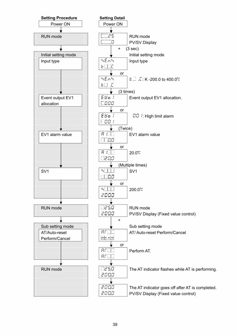
6.1 Example of Initial Setting
(e.g.) BCS2R00-00
Initial Setting Items Example
Input type K -200.0 to 400.0
Event output EV1 allocation High limit alarm
EV1 alarm value 20.0 (Deviation setting from SV)
SV 200.0 (Fixed value control)
PID control is performed. PID constants are calculated by performing AT.
Alarm action
(Fig. 6.1-1)
OFF
ON
200.0 220.0219.0
39
Setting Procedure Setting Detail
Power ON Power ON
RUN mode RUN mode
PV/SV Display
+ (3 sec)
Initial setting mode Initial setting mode
Input type Input type
or
: K -200.0 to 400.0
(3 times)
Event output EV1 Event output EV1 allocation.
allocation
or
: High limit alarm
(Twice)
EV1 alarm value EV1 alarm value
or
20.0
(Multiple times)
SV1 SV1
or
200.0
RUN mode RUN mode
PV/SV Display (Fixed value control)
+
Sub setting mode Sub setting mode
AT/Auto-reset AT/ Auto-reset Perform/Cancel
Perform/Cancel
or
Perform AT.
RUN mode The AT indicator flashes while AT is performing.
The AT indicator goes off after AT is completed.
PV/SV Display (Fixed value control)

40
6.2 Initial Setting Mode
To enter Initial setting mode, press and hold the and keys (in that order) for 3 seconds in RUN mode.
To set (or select) each setting item, use the or key.
To register each setting item, press the key.
Explanation of setting item:
• Upper left: PV Display: Indicates setting characters.
• Lower left: SV Display: Indicates factory default value.
• Right side: Indicates the setting item, explanation of its function, and setting range (or selection item).
Input type
• Selects an input type from thermocouple (10 types), RTD (2 types), direct current
(2 types) and DC voltage (4 types), and the unit / .
Characters,Factory Default Setting Item, Function, Setting Range
Input type
• Selects an input type from thermocouple (10 types), RTD (2 types), direct current(2 types) and DC voltage (4 type), and the unit / .
• When changing the input from DC voltage to other inputs, remove the sensorconnected to this controller first, then change the input. If the input is changedwith the sensor connected, the input circuit may break.
• When changing an input type, refer to Section “8.10 Items to be Initialized byChanging Settings” (p.98).
• Selection item:
K -200 to 1370 K -328 to 2498
K -200.0 to 400.0 K -328.0 to 752.0
J -200 to 1000 J -328 to 1832
R 0 to 1760 R 32 to 3200
S 0 to 1760 S 32 to 3200
B 0 to 1820 B 32 to 3308
E -200 to 800 E -328 to 1472
T -200.0 to 400.0 T -328.0 to 752.0
N -200 to 1300 N -328 to 2372
PL- 0 to 1390 PL- 32 to 2534
C(W/Re5-26) 0 to 2315 C(W/Re5-26) 32 to 4199
Pt100 -200.0 to 850.0 Pt100 -328.0 to1562.0
JPt100 -200.0 to 500.0 JPt100 -328.0 to 932.0
Pt100 -200 to 850 Pt100 -328 to 1562
JPt100 -200 to 500 JPt100 -328 to 932
4 to 20 mA DC -2000 to 10000
0 to 20 mA DC -2000 to 10000
0 to 1 V DC -2000 to 10000
0 to 5 V DC -2000 to 10000
1 to 5 V DC -2000 to 10000
0 to 10 V DC -2000 to 10000
Scaling high limit
• Sets scaling high limit value.
• Setting range: Scaling low limit value to Input range high limit value
DC voltage, current inputs: -2000 to 10000 (*1)
(*1) The placement of the decimal point follows the selection.
Setting characters
Factory default value
Setting item name, function, setting range (or selection item)

41
Characters,Factory Default
Setting Item, Function, Setting Range
Scaling low limit• Sets scaling low limit value.• Setting range: Input range low limit value to Scaling high limit value
DC voltage, current inputs: -2000 to 10000 (*1)
Decimal point place
• Selects decimal point place.• Selection item:
No decimal point
1 digit after decimal point
2 digits after decimal point
3 digits after decimal point
Available only for DC voltage and current inputs
Event output EV1 allocation
• Selects Event output EV1 from the Event Output Allocation Table below.
• When changing Event output EV1, refer to Section “8.10 Items to be Initialized by
Changing Settings” (p.98).
• Selection item:
Event Output Allocation Table
No event
Alarm output, High limit alarm
Alarm output, Low limit alarm
Alarm output, High/Low limits alarmAlarm output, High/Low limitsindependent alarmAlarm output, High/Low limit rangealarmAlarm output, High/Low limit rangeindependent alarm
Alarm output, Process high alarm
Alarm output, Process low alarmAlarm output, High limit with standbyalarmAlarm output, Low limit with standbyalarmAlarm output, High/Low limitswith standby alarmAlarm output, High/Low limitswith standby independent alarm
Heater burnout alarm output
Loop break alarm output
Time signal output Turns OFF or ON during Programcontrol, by setting OFF and ONtime within the step set in [Stepnumber].
Output during AT Turns ON during AT.
Pattern end output Turns ON when Program controlends, and remains ON until turnedOFF by pressing the key.
Output by communication
command
Turns OFF or ON by communicationcommand 00E4H during Serialcommunication.B0 EV1 output 0: OFF
1: ONB1 EV2 output 0: OFF
1: ON(*1)The placement of the decimal point follows the selection.

42
Characters,
Factory DefaultSetting Item, Function, Setting Range
EV1 alarm value 0 Enabled/Disabled
• When EV1 alarm value is 0 (zero), alarm action can be Enabled or Disabled.
• Selection item:
Disabled
Enabled
Available when (Alarm output, High limit alarm) to (Alarm output, High/Low limit range
independent alarm), (Alarm output, High limit with standby alarm) to (Alarm output,
High/Low limits with standby independent alarm) are selected in [Event output EV1 allocation].
EV1 alarm value
• Sets EV1 alarm value.
EV1 alarm value matches EV1 low limit alarm value in the following cases:
(Alarm output, High/Low limits independent alarm), (Alarm
output, High/Low limit range independent alarm), or (Alarm output,
High/Low limits with standby independent alarm) is selected in [Event output EV1
allocation].
• Setting range:
High limit alarm -(Input span) to Input span ( ) (*1) (*2)
Low limit alarm -(Input span) to Input span ( ) (*1) (*2)
High/Low limits alarm 0 to Input span ( ) (*1) (*2)
High/Low limits independent
alarm
0 to Input span ( ) (*1) (*2)
High/Low limit range alarm 0 to Input span ( ) (*1) (*2)
High/Low limit range
independent alarm
0 to Input span ( ) (*1) (*2)
Process high alarm Input range low limit to Input range high limit (*1) (*3)
Process low alarm Input range low limit to Input range high limit (*1) (*3)
High limit with standby alarm -(Input span) to Input span ( ) (*1) (*2)
Low limit with standby alarm -(Input span) to Input span ( ) (*1) (*2)
High/Low limits with standby
alarm
0 to Input span ( ) (*1) (*2)
High/Low limits with standby
independent alarm
0 to Input span ( ) (*1) (*2)
Available when any alarm from (Alarm output, High limit alarm) to (Alarm output, High/Low
limits with standby independent alarm) is selected in [Event output EV1 allocation].
EV1 high limit alarm value
• Sets EV1 high limit alarm value.
This value is available only for the following.
(Alarm output, High/Low limits independent alarm), (Alarm
output, High/Low limit range independent alarm), or (Alarm output,
High/Low limits with standby independent alarm) is selected in [Event output EV1
allocation].
• Setting range: Same as those of EV1 alarm value(*1) The placement of the decimal point follows the selection.
(*2) For DC voltage, current inputs, the input span is the same as the scaling span.
(*3) For DC voltage, current inputs, input range low (or high) limit value is the same as scaling low (or high) limit value.

43
Characters,
Factory DefaultSetting Item, Function, Setting Range
EV1 alarm hysteresis
• Sets EV1 alarm hysteresis.
• Setting range: 0.1 to 1000.0 ( ),
DC voltage, current inputs: 1 to 10000 (*1)
Available when any alarm from (Alarm output, High limit alarm) to (Alarm output, High/Low
limits with standby independent alarm) is selected in [Event output EV1 allocation].
EV1 alarm delay time
• Sets EV1 alarm action delay time.
When setting time has elapsed after the input enters the alarm output range, the
alarm is activated.
• Setting range: 0 to 10000 seconds
Available when any alarm from (Alarm output, High limit alarm) to (Alarm output, High/Low
limits with standby independent alarm) is selected in [Event output EV1 allocation].
EV1 alarm Energized/De-energized
• Selects Energized/De-energized status for EV1 alarm.
(Refer to ‘EV1/EV2 Energized/De-energized’ on p.50.)
• Selection item:
Energized
De-energized
Available when any alarm from (Alarm output, High limit alarm) to (Alarm output, High/Low
limits with standby independent alarm) is selected in [Event output EV1 allocation].
TS1 output step number
• Sets the step number at which Time signal output TS1 will be turned OFF or ON
during Program control.
(Refer to ‘Time Signal Output’ on p.52.)
• Setting range: 1 to 9
Available only when (Time signal output) is selected in [Event output EV1 allocation].
TS1 OFF time
• Sets Time signal output TS1 OFF time.
(Refer to ‘Time Signal Output’ on p.52.)
• Setting range: 00:00 to 99:59 (*2)
Available only when (Time signal output) is selected in [Event output EV1 allocation].
TS1 ON time
• Sets Time signal output TS1 ON time.
(Refer to ‘Time Signal Output’ on p.52.)
• Setting range: 00:00 to 99:59 (*2)
Available only when (Time signal output) is selected in [Event output EV1 allocation].
(*1)The placement of the decimal point follows the selection.
(*2) Time unit follows the selection in [Step time unit].

44
Characters,Factory Default
Setting Item, Function, Setting Range
Event output EV2 allocation
• Selects Event output EV2 from the Event Output Allocation Table below.
• When changing Event output EV2, refer to Section “8.10 Items to be Initialized by
Changing Settings” (p.98).
• Selection item:
Event Output Allocation Table
No event
Alarm output, High limit alarm
Alarm output, Low limit alarm
Alarm output, High/Low limits alarm
Alarm output, High/Low limitsindependent alarm
Alarm output, High/Low limit rangealarm
Alarm output, High/Low limit rangeindependent alarm
Alarm output, Process high alarm
Alarm output, Process low alarm
Alarm output, High limit withstandby alarm
Alarm output, Low limit with standbyalarm
Alarm output, High/Low limits withstandby alarm
Alarm output, High/Low limits withstandby independent alarm
Heater burnout alarm output
Loop break alarm output
Time signal output Turns OFF or ON during Programcontrol, by setting OFF and ONtimes within the step set in [Stepnumber].
Output during AT Turns ON during AT.
Pattern end output Turns ON when Program controlends, and remains ON until turnedOFF by pressing the key.
Output by communication command Turns OFF or ON by communicationcommand 00E4H during Serialcommunication.B0 EV1 output 0: OFF 1: ONB1 EV2 output 0: OFF 1: ON
Heating/Cooling controlrelay contact output
Works as Control output OUT2(Heating/Cooling control).
Available only when Event output EV2 (EV2, EV2+D options) is ordered.
EV2 alarm value 0 Enabled/Disabled
• When EV2 alarm value is 0 (zero), alarm action can be Enabled or Disabled.
• Selection item:
Disabled
EnabledAvailable only when Event output EV2 (EV2, EV2+D options) is ordered.
Available when (Alarm output, High limit alarm) to (Alarm output, High/Low limit range
independent alarm), (Alarm output, High limit with standby alarm) to (Alarm output,
High/Low limits with standby independent alarm) are selected in [Event output EV2 allocation].
(*1) Not available if Heating/Cooling control (EV2+D option) is ordered.

45
Characters,
Factory DefaultSetting Item, Function, Setting Range
EV2 alarm value
• Sets EV2 alarm value.
EV2 alarm value matches EV2 low limit alarm value in the following cases:
(Alarm output, High/Low limits independent alarm), (Alarm output,
High/Low limit range independent alarm), or (Alarm output, High/Low limits
with standby independent alarm) is selected in [Event output EV2 allocation].
• Setting range:
High limit alarm -(Input span) to Input span ( ) (*1) (*2)
Low limit alarm -(Input span) to Input span ( ) (*1) (*2)
High/Low limits alarm 0 to Input span ( ) (*1) (*2)
High/Low limits independent
alarm
0 to Input span ( ) (*1) (*2)
High/Low limit range alarm 0 to Input span ( ) (*1) (*2)
High/Low limit range
independent alarm
0 to Input span ( ) (*1) (*2)
Process high alarm Input range low limit to Input range high limit (*1) (*3)
Process low alarm Input range low limit to Input range high limit (*1) (*3)
High limit with standby alarm -(Input span) to Input span ( ) (*1) (*2)
Low limit with standby alarm -(Input span) to Input span ( ) (*1) (*2)
High/Low limits with standby 0 to Input span ( ) (*1) (*2)
High/Low limits with standby
independent alarm
0 to Input span ( ) (*1) (*2)
Available only when Event output EV2 (EV2, EV2+D options) is ordered.
Available when any alarm from (Alarm output, High limit alarm) to (Alarm output, High/Low
limits with standby independent alarm) is selected in [Event output EV2 allocation].
EV2 high limit alarm value
• Sets EV2 high limit alarm value.
This value is available only for the following:
(Alarm output, High/Low limits independent alarm), (Alarm output,
High/Low limit range independent alarm), or (Alarm output, High/Low limits
with standby independent alarm) is selected in [Event output EV2 allocation].
• Setting range: Same as those of EV2 alarm value
Available only when Event output EV2 (EV2, EV2+D options) is ordered.
EV2 alarm hysteresis
• Sets EV2 alarm hysteresis.
• Setting range: 0.1 to 1000.0 ( ),
DC voltage, current inputs: 1 to 10000 (*1)
Available only when Event output EV2 (EV2, EV2+D options) is ordered.
Available when any alarm from (Alarm output, High limit alarm) to (Alarm output, High/Low
limits with standby independent alarm) is selected in [Event output EV2 allocation].
EV2 alarm delay time
• Sets EV2 alarm action delay time.
When setting time has elapsed after the input enters the alarm output range, the
alarm is activated.
• Setting range: 0 to 10000 secondsAvailable only when Event output EV2 (EV2, EV2+D options) is ordered.
Available when any alarm from (Alarm output, High limit alarm) to (Alarm output, High/Low
limits with standby independent alarm) is selected in [Event output EV2 allocation].
(*1) The placement of the decimal point follows the selection.
(*2) For DC voltage, current inputs, the input span is the same as the scaling span.
(*3) For DC voltage, current inputs, input range low (or high) limit value is the same as scaling low (or high) limit value.

46
Characters,
Factory DefaultSetting Item, Function, Setting Range
EV2 alarm Energized/De-energized
• Selects Energized/De-energized status for EV2 alarm.
(Refer to ‘EV1/EV2 Energized/De-energized’ on p.50.)
• Selection item:
Energized
De-energized
Available only when Event output EV2 (EV2, EV2+D options) is ordered.
Available when any alarm from (Alarm output, High limit alarm) to (Alarm output, High/Low
limits with standby independent alarm) is selected in [Event output EV2 allocation].
TS2 output step number
• Sets the step number at which Time signal output TS2 will be turned OFF or ON
during Program control.
(Refer to ‘Time Signal Output’ on p.52.)
• Setting range: 1 to 9
Available only when (Time signal output) is selected in [Event output EV2 allocation].
TS2 OFF time
• Sets Time signal output TS2 OFF time.
(Refer to ‘Time Signal Output’ on p.52.)
• Setting range: 00:00 to 99:59 (*1)
Available only when (Time signal output) is selected in [Event output EV2 allocation].
TS2 ON time
• Sets Time signal output TS2 ON time.
(Refer to ‘Time Signal Output’ on p.52.)
• Setting range: 00:00 to 99:59 (*1)
Available only when (Time signal output) is selected in [Event output EV2 allocation].
and CT1 current
value are alternately
indicated on the PV
Display.
Heater burnout alarm 1 value
• Sets the heater current value for Heater burnout alarm 1.
Characters and CT1 current value are alternately indicated on the PV
Display.
When OUT1 is ON, the CT1 current value is updated.
When OUT1 is OFF, the unit memorizes the previous value when OUT1 was ON.
Upon returning to set limits, the alarm will stop.
• Setting range:
20 A: 0.0 to 20.0 A
100 A: 0.0 to 100.0 A
Setting to 0.0 disables the alarm.
Not available for the direct current output type.
Available when Heater burnout alarm (C5W, EIW, W options) is ordered.
(*1) Time unit follows the selection in [Step time unit].

47
Characters,
Factory DefaultSetting Item, Function, Setting Range
and CT2
current value are
alternately
indicated on the
PV Display.
Heater burnout alarm 2 value
• Sets the heater current value for Heater burnout alarm 2.
Available only when using 3-phase.
Characters and CT2 current value are alternately indicated on the PV
Display.
When OUT1 is ON, the CT2 current value is updated.
When OUT1 is OFF, the unit memorizes the previous value when OUT1 was ON.
Upon returning to set limits, the alarm will stop.
• Setting range:
20 A: 0.0 to 20.0 A
100 A: 0.0 to 100.0 A
Setting to 0.0 disables the alarm.
Not available for the direct current output type.
Available only when Heater burnout alarm (C5W, EIW, W options) is ordered.
Loop break alarm time
• Sets the time to assess the Loop break alarm.
Refer to ‘Loop Break Alarm’ on p.50.
• Setting range: 0 to 200 minutes
Setting to 0 (zero) disables the alarm.
Loop break alarm span
• Sets the temperature to assess the Loop break alarm.
Refer to ’Loop Break Alarm’ on p.50.
• Setting range: 0 to 150 ( ), or 0.0 to 150.0 ( )
DC voltage, current inputs: 0 to 1500 (*1)
Setting to 0 (zero) disables the alarm.
Event input DI1 allocation
• Selects Event input DI1 from Event Input Allocation Table.
(Refer to ’Event Input’ on p.51.)
• Selection item:
Event Input Allocation TableEvent input
functionInput ON(Closed)
Input OFF(Open) Remarks
No event
Set value memory
Control ON/OFF Control OFF Control ON Control output OFF
function
Direct/Reverse
action
Direct
action
Reverse
action
Always effective
Preset output 1
ON/OFF
Preset
output
Usual
control
If sensor is burnt out,
the unit maintains
control with the
preset MV.
Preset output 2
ON/OFF
Preset
output
Usual
control
The unit maintains
control with the
preset MV.
Auto/Manual
control
Manual
control
Automatic
control
Effective when
Auto/Manual control
is selected in [OUT/
OFF key function].
(*1) The placement of the decimal point follows the selection.

48
Characters,
Factory DefaultSetting Item, Function, Setting Range
Event input
function
Input ON
(Closed)
Input OFF
(Open)Remarks
Remote/Local Remote Local Effective when
External setting input
(EIT option) is
ordered.
Program control
RUN/STOP
RUN STOP Level action when
power is turned onProgram control
Holding/Not
holding
Holding Not holding Level action when
power is turned on
Program control
Advance function
Advance
function
Usual
control
Integral action
Holding
Integral
action
Holding
Usual
integral
action
Control continues
with the integral
value being held.For BCS2, available only when Event input (EIW, EIT, EI options) is ordered.For BCR2/BCD2, available when Serial communication (C5W option) or Event input (EIW, EIT, EI options) is
ordered.
Event input DI2 allocation
• Selects Event input DI2 from Event Input Allocation Table.
(Refer to ‘Event Input’ on p.51)
• Selection item:
Same as those of Event input DI1 allocationFor BCS2, available only when Event input (EIW, EI option) is ordered.
For BCR2/BCD2, available when Serial communication (C5W option) or Event input (EIW, EIT, EI options) is
ordered.
External setting input high limit
• Sets External setting input high limit value.
This value corresponds to 20 mA in direct current input.
• Setting range: External setting input low limit to Input range high limit (*1)
Available only when External setting input (EIT option) is ordered.
External setting input low limit
• Sets External setting input low limit value.
This value corresponds to 4 mA in direct current input.
• Setting range: Input range low limit to External setting input high limit (*1)
Available only when External setting input (EIT option) is ordered.
Transmission output type
• Selects transmission output type.
• When changing transmission output type, refer to Section “8.10 Items to be
Initialized by Changing Settings” (p.98).
• Selection item:
PV transmission
SV transmission
MV transmission
DV transmission
Available only when Transmission output (EIT option) is ordered.
(*1) The placement of the decimal point follows the selection.

49
Characters,
Factory DefaultSetting Item, Function, Setting Range
Transmission output high limit
• Sets the Transmission output high limit value.
This value correponds to 20 mA in direct current output.
• Setting range:
PV, SV transmission Transmission output low limit to Input range high limit value
DC voltage, current inputs: -2000 to 10000
MV transmission Transmission output low limit to 105.0%
DV transmission Transmission output low limit to Scaling span (*1)
Available only when Transmission output (EIT option) is ordered.
Transmission output low limit
• Sets the Transmission output low limit value.
This value correponds to 4 mA in direct current output.
• Selection item:
PV, SV transmission Input range low limit to Transmission output high limit value
DC voltage, current inputs: -2000 to 10000
MV transmission -5.0% to Transmission output high limit value
DV transmission -Scaling span to Transmission output high limit value (*1)
Available only when Transmission output (EIT option) is ordered.
SV1
• Sets SV1.
• Setting range: Scaling low limit to Scaling high limit (*1)
Available when Control output OFF function or Auto/Manual control is selected in [OUT/OFF key function].
SV2
• Sets SV2.
• Setting range: Scaling low limit to Scaling high limit (*1)
Available for the following:
• When Control output OFF function or Auto/Manual control is selected in [OUT/OFF key function].
• For BCS2, Event input (EIW, EIT, EI options) is ordered.
• For BCR2/BCD2, Serial communication (C5W option) or Event input (EIW, EIT, EI options) is ordered.
• When (Set value memory) is selected in [Event input DI1/DI2 allocation].
SV3
• Sets SV3.
• Setting range: Scaling low limit to Scaling high limit (*1)
Available for the following:
• When Control output OFF function or Auto/Manual control is selected in [OUT/OFF key function].
• For BCS2, Event input (EIW, EI options) is ordered.
• For BCR2/BCD2, Serial communication (C5W option) or Event input (EIW, EIT, EI options) is ordered.
• When (Set value memory) is selected in [Event input DI1/DI2 allocation].
SV4
• Sets SV4.
• Setting range: Scaling low limit to Scaling high limit (*1)
Available for the following:
• When Control output OFF function or Auto/Manual control is selected in [OUT/OFF key function].
• For BCS2, Event input (EIW, EI options) is ordered
• For BCR2/BCD2, Serial communication (C5W option) or Event input (EIW, EIT, EI options) is ordered.
• When (Set value memory) is selected in [Event input DI1/DI2 allocation].
(*1) The placement of the decimal point follows the selection.

50
[EV1/EV2 Energized/De-energized]
When (Energized) is selected, Event output 1 or 2 is conductive (ON) while the EV1/EV2
indicator is lit.
Event output 1 or 2 is not conductive (OFF) while the EV1/EV2 indicator is not lit.
When (De-energized) is selected, Event output 1 or 2 is not conductive (OFF) while the
EV1/EV2 indicator is lit.
Event output 1 or 2 is conductive (ON) while the EV1/EV2 indicator is not lit.
High limit alarm (when Energized is set) High limit alarm (when De-energized is set)
(Fig. 6.2-1) (Fig. 6.2-2)
EV1 value and EV1 hysteresis represent EV1 alarm value and EV1 alarm hysteresis respectively.
For EV2, read “EV2” for “EV1”.
[Loop Break Alarm]
When the control action is Reverse (Heating) control:
If the PV does not reach the Loop break alarm span setting within the time allotted to assess the Loop
break alarm (after the MV has reached 100% or the OUT high limit value), the alarm will be activated.
Likewise, if the PV does not drop to the Loop break alarm span setting within the time allotted to
assess the Loop break alarm (after the MV has reached 0% or the OUT low limit value), the alarm will
be activated.
When the control action is Direct (Cooling) control:
If the PV does not drop to the Loop break alarm span setting within the time allotted to assess the Loop
break alarm (after the MV has reached 100% or the OUT high limit value), the alarm will be activated.
Likewise, if the PV does not reach the Loop break alarm span setting within the time allotted to assess
the Loop break alarm (after the MV has reached 0% or the OUT low limit value), the alarm will be
activated.
If Serial communication (C5W, C5 options) is added, status can be read by reading Status flag 1.
OFF
ON
EV1 hysteresis
SV + EV1 value
OFF
ON
SV + EV1 value
EV1 hysteresis

51
[Event Input]
• If (Set value memory) is selected, the set value memory number will be as follows.
When only Event input DI1 is selected.
Set value memory number SV1 SV2
DI1 Open Closed
When only Event input DI2 is selected.
Set value memory number SV1 SV2
DI2 Open Closed
When both Event input DI1, DI2 are selected.
Set value memory number SV1 SV2 SV3 SV4
DI1 Open Closed Open Closed
DI2 Open Open Closed Closed
• Preset value of (Preset output 1 ON/OFF) and (Preset output 2 ON/OFF) can
be set in [OUT1/OUT2 MV preset value (p.77)] in Engineering mode 1.
• If (Preset output 2 ON/OFF) is selected in [Event input DI1 allocation], and
(Auto/Manual control) is selected in Event input DI2 allocation, and if DI1-COM and DI2-COM
terminals are turned ON (Closed) simultaneously, then Preset output 2 will be given priority, and
control starts with the MV set in [OUT1/OUT2 MV preset value (p.77)] in Engineering mode 1.
In this case, control will be switched to manual control, and MV cannot be changed via keypad.
• Signal edge action from OFF to ON / ON to OFF is engaged.
If (Program control RUN/STOP) is selected in [Event input DI1 allocation], the following
action will be performed.
However, only when power is turned ON, Level action is engaged - which follows the input status
[ON (Closed) or OFF (Open)] of Event input DI1.
(Fig. 6.2-3)
• OR calculation [if any one is ON (closed), the function activates] begins if the same functions except
(Set value memory) have been selected in [Event input DI1/DI2 allocation].
If any terminals DI1-COM or DI2-COM is ON (closed), the function activates.
• If any function except (Program control Advance function) is selected in [Event input DI1/DI2
allocation], Level action is engaged when power is turned ON - which follows the input status [ON
(Closed) or OFF (Open)] of Event input DI1/DI2.
17-18 [DI1-COM]:OFF (Open)Standby mode
Standby mode
17-18 [DI1-COM]:ON (Closed)Program control performs.
Program control RunProgram control Stop(Standby mode)
17-18 [DI1-COM]:OFF (Open)Program control stops(Standby mode).Terminals 17-18
[DI1-COM] OFF (Open)
Program control performs when“17-18 [DI1-COM]” changes fromOFF (Open) to ON (Closed)..
Program control stops (Standby mode)when “17-18 [DI1-COM]” changes fromON (Closed) to OFF (Open)..
Terminals 17-18[DI1-COM] ON (Closed)
Controller status

52
[Time Signal Output]
Time signal output activates during Time signal output ON time within each step (number).
Time signal output ON time follows Time signal output OFF time after the program control starts.
The following program pattern shows that the temperature rises to 200 for 1 hour, and stays
at 200 for 2 hours after Program control starts.
Step 1 2
Step SV 200 200
Step time 1:00 2:00
Time signal output (Fig. 6.2-4) is shown when set as follows.
• TS1/TS2 output step number: 2
• TS1/TS2 OFF time: 0:30
• TS1/TS2 ON time: 1:00
Step 1 2
Time signal output
(Fig. 6.2-4)
Time signal output is effective within the step set in [TS1/TS2 output step number].
For example, if TS1/TS2 ON time is set to “2:00” at the above, Time signal output
is turned OFF at the moment when Step 2 is completed.
200
0
1:00 2:00
Program control RUN
ON
OFF
0:30 1:00
OFF time ON time
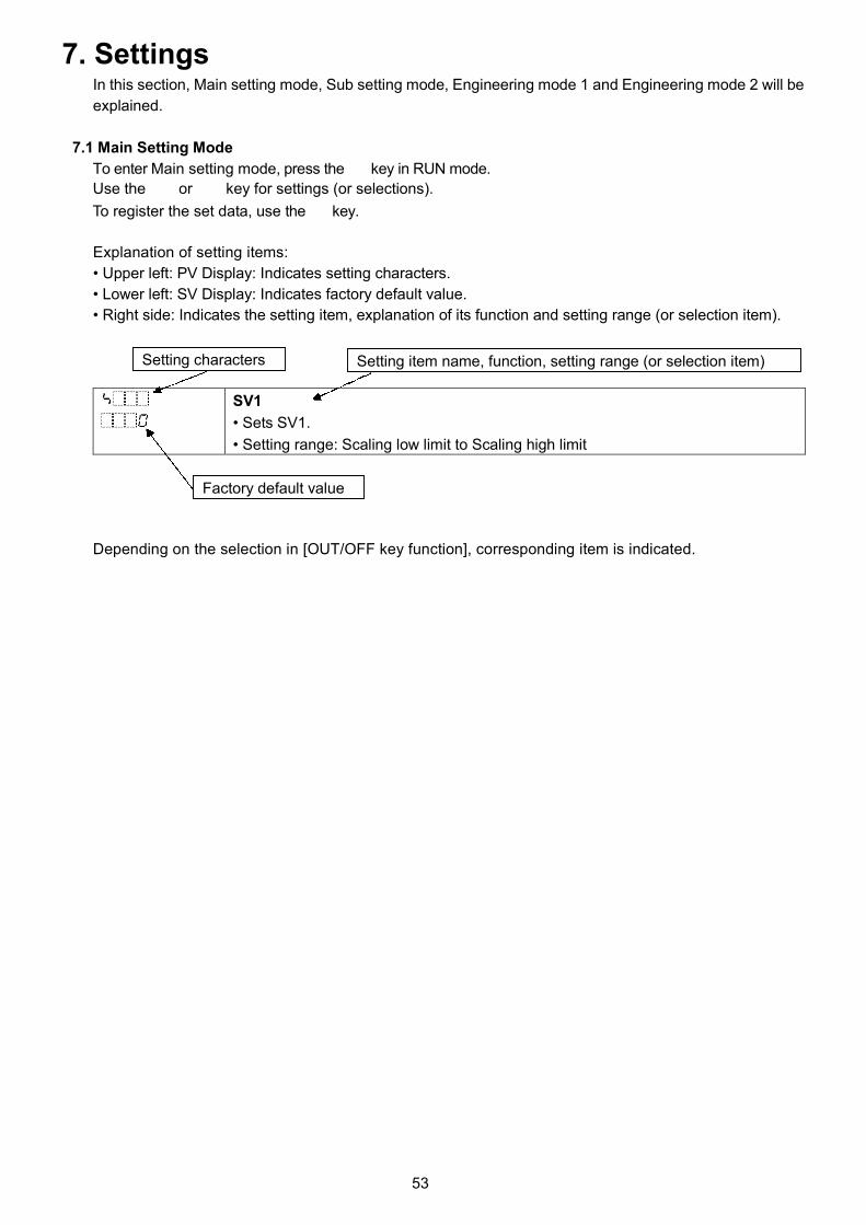
53
7. SettingsIn this section, Main setting mode, Sub setting mode, Engineering mode 1 and Engineering mode 2 will be
explained.
7.1 Main Setting Mode
To enter Main setting mode, press the key in RUN mode.
Use the or key for settings (or selections).
To register the set data, use the key.
Explanation of setting items:
• Upper left: PV Display: Indicates setting characters.
• Lower left: SV Display: Indicates factory default value.
• Right side: Indicates the setting item, explanation of its function and setting range (or selection item).
SV1
• Sets SV1.
• Setting range: Scaling low limit to Scaling high limit
Depending on the selection in [OUT/OFF key function], corresponding item is indicated.
Setting characters
Factory default value
Setting item name, function, setting range (or selection item)

54
When ‘Control output OFF function’ or ‘Auto/Manual control’ is selected in [OUT/OFF key function]:
Characters,
Factory DefaultSetting Item, Function, Setting Range
SV1
• Sets SV1.
Corresponds to [SV1] in Initial setting mode.
• Setting range:
Scaling low limit to Scaling high limit (*1)
SV2 (*2)
• Sets SV2.
Corresponds to [SV2] in Initial setting mode.
• Setting range:
Scaling low limit to Scaling high limit (*1)
SV3 (*2)
• Sets SV3.
Corresponds to [SV3] in Initial setting mode.
• Setting range:
Scaling low limit to Scaling high limit (*1)
SV4 (*2)
• Sets SV4.
Corresponds to [SV4] in Initial setting mode.
• Setting range:
Scaling low limit to Scaling high limit (*1)
(*1) The placement of the decimal point follows the selection.
(*2) When (Set value memory) is selected in [Event input DI1 allocation] or [Event input DI2 allocation], SV1 and SV2 can be set.
When (Set value memory) is selected in both [Event input DI1 allocation] and [Event input DI2 allocation], SV1, SV2, SV3
and SV4 can be set.
Available for the following:
• For BCS2, when Event input (EIW, EI option) is ordered
• For BCR2/BCD2, when Serial communication (C5W option) or Event input (EIW, EIT, EI option) is ordered.
• When (Set value memory) is selected in [Event input DI1/DI2 allocation]
When ‘Program control’ is selected in [OUT/OFF key function]:
Characters,
Factory DefaultSetting Item, Function, Setting Range
Step 1 SV
• Sets Step 1 SV.
• Setting range:
Scaling low limit to Scaling high limit (*1)
Step 1 time
• Sets Step 1 time.
• Setting range:
, or 00:00 to 99:59
If is set, Step 1 time will be held, and Fixed value control will be performed
using Step 1 SV.
Step 1 wait value
• Sets Step 1 wait value.
• Setting range:
0 to 20% of input span
DC voltage, current inputs: 0 to 20% of scaling span (*1)
Setting the value to 0 disables this Wait function.
(*1) The placement of the decimal point follows the selection.

55
Characters,
Factory DefaultSetting Item, Function, Setting Range
Step 2 SV
• Sets Step 2 SV.
• Setting range:Scaling low limit to Scaling high limit (*1)
Step 2 time
• Sets Step 2 time.
• Setting range:
, or 00:00 to 99:59
If is set, Step 2 time will be held, and Fixed value control will be performed
using Step 2 SV.
Step 2 wait value
• Sets Step 2 wait value.
• Setting range:
0 to 20% of input span
DC voltage, current inputs: 0 to 20% of scaling span (*1)
Setting the value to 0 disables this Wait function.
Step 3 SV
• Sets Step 3 SV.
• Setting range:Scaling low limit to Scaling high limit (*1)
Step 3 time
• Sets Step 3 time.
• Setting range:
, or 00:00 to 99:59
If is set, Step 3 time will be held, and Fixed value control will be performed
using Step 3 SV.
Step 3 wait value
• Sets Step 3 wait value.
• Setting range:
0 to 20% of input span
DC voltage, current inputs: 0 to 20% of scaling span (*1)
Setting the value to 0 disables this Wait function.
Step 4 SV
• Sets Step 4 SV.
• Setting range:Scaling low limit to Scaling high limit (*1)
Step 4 time
• Sets Step 4 time.
• Setting range:
, or 00:00 to 99:59
If is set, Step 4 time will be held, and Fixed value control will be performed
using Step 4 SV.
(*1) The placement of the decimal point follows the selection.

56
Characters,
Factory DefaultSetting Item, Function, Setting Range
Step 4 wait value
• Sets Step 4 wait value.
• Setting range:
0 to 20% of input span
DC voltage, current inputs: 0 to 20% of scaling span (*1)
Setting the value to 0 disables this Wait function.
Step 5 SV
• Sets Step 5 SV.
• Setting range:
Scaling low limit to Scaling high limit (*1)
Step 5 time
• Sets Step 5 time.
• Setting range:
, or 00:00 to 99:59
If is set, Step 5 time will be held, and Fixed value control will be performed
using Step 5 SV.
Step 5 wait value
• Sets Step 5 wait value.
• Setting range:
0 to 20% of input span
DC voltage, current inputs: 0 to 20% of scaling span (*1)
Setting the value to 0 disables this Wait function.
Step 6 SV
• Sets Step 6 SV.
• Setting range:
Scaling low limit to Scaling high limit (*1)
Step 6 time
• Sets Step 6 time.
• Setting range:
, or 00:00 to 99:59
If is set, Step 6 time will be held, and Fixed value control will be performed
using Step 6 SV.
Step 6 wait value
• Sets Step 6 wait value.
• Setting range:
0 to 20% of input span
DC voltage, current inputs: 0 to 20% of scaling span (*1)
Setting the value to 0 disables this Wait function.
Step 7 SV
• Sets Step 7 SV.
• Setting range:
Scaling low limit to Scaling high limit (*1)
(*1) The placement of the decimal point follows the selection.
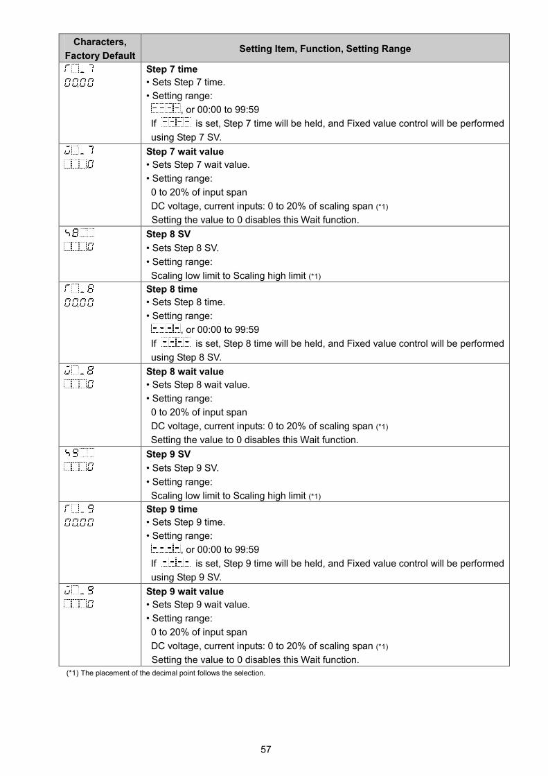
57
Characters,
Factory DefaultSetting Item, Function, Setting Range
Step 7 time
• Sets Step 7 time.
• Setting range:
, or 00:00 to 99:59
If is set, Step 7 time will be held, and Fixed value control will be performed
using Step 7 SV.
Step 7 wait value
• Sets Step 7 wait value.
• Setting range:
0 to 20% of input span
DC voltage, current inputs: 0 to 20% of scaling span (*1)
Setting the value to 0 disables this Wait function.
Step 8 SV
• Sets Step 8 SV.
• Setting range:
Scaling low limit to Scaling high limit (*1)
Step 8 time
• Sets Step 8 time.
• Setting range:
, or 00:00 to 99:59
If is set, Step 8 time will be held, and Fixed value control will be performed
using Step 8 SV.
Step 8 wait value
• Sets Step 8 wait value.
• Setting range:
0 to 20% of input span
DC voltage, current inputs: 0 to 20% of scaling span (*1)
Setting the value to 0 disables this Wait function.
Step 9 SV
• Sets Step 9 SV.
• Setting range:
Scaling low limit to Scaling high limit (*1)
Step 9 time
• Sets Step 9 time.
• Setting range:
, or 00:00 to 99:59
If is set, Step 9 time will be held, and Fixed value control will be performed
using Step 9 SV.
Step 9 wait value
• Sets Step 9 wait value.
• Setting range:
0 to 20% of input span
DC voltage, current inputs: 0 to 20% of scaling span (*1)
Setting the value to 0 disables this Wait function.
(*1) The placement of the decimal point follows the selection.

58
7.2 Sub Setting Mode
To enter Sub setting mode, press the and keys (in that order) together in RUN mode.
Use the or key for settings (or selections).
To register the set data, use the key.
Explanation of setting items:
• Upper left: PV Display: Indicates setting characters.
• Lower left: SV Display: Indicates factory default value.
• Right side: Indicates the setting item, explanation of its function and setting range (or selection item).
AT/Auto-reset Perform/Cancel
• Selects AT or ‘AT on startup’ Perform/Cancel in PID control, or Auto-reset
Perform/Cancel in P or PD control.
Characters,
Factory DefaultSetting Item, Function, Setting Range
AT/Auto-reset Perform/Cancel
• Selects AT or ‘AT on startup’ Perform/Cancel in PID control action, or Auto-reset
Perform/Cancel in P or PD control action.
Refer to Sections ‘8.5 Setting PID Constants (by Performing AT)’ (p. 84), and
‘8.6 Performing Auto-reset’ (p. 87).
• Selection item:
AT/AT on startup/Auto-reset Cancel
AT Perform
‘AT on startup’ Perform
Auto-reset Perform
Not available for ON/OFF control or PI control.
OUT1 proportional band
• Sets OUT1 proportional band.
• Setting range: 0 to input span ( )
Thermocouple, RTD input without decimal point: 0 to input span ( )
Thermocouple, RTD input with decimal point: 0.0 to input span ( )
DC voltage, current inputs: 0.0 to 1000.0%
OUT1 becomes ON/OFF control when set to 0 or 0.0.
Integral time
• Sets the integral time.
Auto-reset can be performed when PD is control action (I = 0).
• Setting range: 0 to 3600 seconds
Setting the value to 0 disables integral action.
Not available if OUT1 is in ON/OFF control.
Derivative time
• Sets the derivative time.
• Setting range: 0 to 1800 seconds
Setting the value to 0 disables derivative action.
Not available if OUT1 is in ON/OFF control.
Setting characters
Factory default value
Setting item name, function, setting range (or selection item)
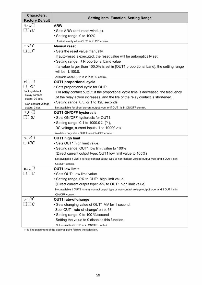
59
Characters,
Factory DefaultSetting Item, Function, Setting Range
ARW
• Sets ARW (anti-reset windup).
• Setting range: 0 to 100%
Available only when OUT1 is in PID control.
Manual reset
• Sets the reset value manually.
If auto-reset is executed, the reset value will be automatically set.
• Setting range: Proportional band value
If a value larger than 100.0% is set in [OUT1 proportional band], the setting range
will be 100.0.
Available when OUT1 is in P or PD control.
Factory default:
• Relay contact
output: 30 sec.
• Non-contact voltage
output: 3 sec.
OUT1 proportional cycle
• Sets proportional cycle for OUT1.
For relay contact output, if the proportional cycle time is decreased, the frequency
of the relay action increases, and the life of the relay contact is shortened.
• Setting range: 0.5, or 1 to 120 seconds
Not available for direct current output type, or if OUT1 is in ON/OFF control.
OUT1 ON/OFF hysteresis
• Sets ON/OFF hysteresis for OUT1.
• Setting range: 0.1 to 1000.0 ( ),
DC voltage, current inputs: 1 to 10000 (*1)
Available only when OUT1 is in ON/OFF control.
OUT1 high limit
• Sets OUT1 high limit value.
• Setting range: OUT1 low limit value to 100%
(Direct current output type: OUT1 low limit value to 105%)
Not available if OUT1 is relay contact output type or non-contact voltage output type, and if OUT1 is in
ON/OFF control.
OUT1 low limit
• Sets OUT1 low limit value.
• Setting range: 0% to OUT1 high limit value
(Direct current output type: -5% to OUT1 high limit value)
Not available if OUT1 is relay contact output type or non-contact voltage output type, and if OUT1 is in
ON/OFF control.
OUT1 rate-of-change
• Sets changing value of OUT1 MV for 1 second.
See ‘OUT1 rate-of-change’ on p. 63.
• Setting range: 0 to 100 %/second
Setting the value to 0 disables this function.
Not available if OUT1 is in ON/OFF control.
(*1) The placement of the decimal point follows the selection.

60
SV
OUT2 proportional band
Air cooling
Oil coolingWater cooling
Characters,
Factory DefaultSetting Item, Function, Setting Range
OUT2 cooling method
• Selects OUT2 cooling method from air, oil or water cooling.
(Fig. 7.2-1)
• Selection item:
Air cooling (linear characteristics)
Oil cooling (1.5th power of the linear characteristics)
Water cooling (2nd power of the linear characteristics)
Available when Heating/Cooling control [DS, DA, EV2(*1), EV2+D options] is ordered.
Not available if OUT1 is in ON/OFF control or if OUT2 is in ON/OFF control.
OUT2 proportional band
• Sets the proportional band for OUT2.
• Setting range:
Thermocouple, RTD input without decimal point: 0 to Input span ( )
Thermocouple, RTD input with decimal point: 0.0 to Input span ( )
DC voltage, current inputs: 0.0 to 1000.0%
When set to 0 or 0.0, OUT2 becomes ON/OFF control, and the item selected in
[OUT2 cooling method] will be disabled.
Available when Heating/Cooling control [DS, DA, EV2(*1), EV2+D option] is ordered.
Not available if OUT1 is in ON/OFF control.
Factory default:
EV2(*2), EV2+DR:
30 sec.
DS: 3 sec.
OUT2 proportional cycle
• Sets proportional cycle for OUT2.
For relay contact output, if the proportional cycle time is decreased, the frequency
of the relay action increases, and the life of the relay contact is shortened.
• Setting range: 0.5, or 1 to 120 seconds
Available when Heating/Cooling control [DS, DA, EV2(*1), EV2+D ] is ordered.
Not available if OUT1 is in ON/OFF control, OUT2 is in ON/OFF control or OUT2 is direct current output type.
OUT2 ON/OFF hysteresis
• Sets ON/OFF hysteresis for OUT2.
• Setting range: 0.1 to 1000.0 ( ),
DC voltage, current inputs: 1 to 10000 (*2)
Available when Heating/Cooling control [DS, DA, EV2(*1), EV2+D option] is ordered.
Available when OUT2 is in ON/OFF control.
OUT2 high limit
• Sets OUT2 high limit value.
• Setting range: OUT2 low limit value to 100%
(Direct current output type: OUT2 low limit value to 105%)
Available when Heating/Cooling control [DS, DA, EV2(*1), EV2+D ] is ordered.
Not available if OUT2 is relay contact output type or non-contact voltage output type and OUT1 is in ON/OFF
control.
Not available if OUT2 is relay contact output type or non-contact voltage output type and OUT2 is in ON/OFF
control.
(*1) When (Heating/Cooling control relay contact output) is selected in [Event output EV2 allocation]}.
(*2) The placement of the decimal point follows the selection.

61
Characters,
Factory DefaultSetting Item, Function, Setting Range
OUT2 low limit
• Sets OUT2 low limit value.
• Setting range: 0% to OUT2 high limit value
(Direct current output type: -5% to OUT2 high limit value)Available when Heating/Cooling control [DS, DA, EV2(*1), EV2+D ] is ordered.Not available if OUT2 is relay contact output type or non-contact voltage output type and OUT1 is in ON/OFF
control.Not available if OUT2 is relay contact output type or non-contact voltage output type and OUT2 is in ON/OFFcontrol.
Overlap/Dead band
• Sets the overlap band or dead band for OUT1 and OUT2.
+ Set value: Dead band
– Set value: Overlap band
• Setting range: -200.0 to 200.0 ( ),
DC voltage, current inputs: -2000 to 2000 (*2)
Available when Heating/Cooling control [DS, DA, EV2(*1), EV2+D ] is ordered.
Direct/Reverse action
• Selects either Reverse (Heating) or Direct (Cooling) control action.
Reverse (Heating) action
Direct (Cooling) action
EV1 alarm value
• Sets EV1 alarm value.
Corresponds to [EV1 alarm value] in Initial setting mode.
EV1 alarm value matches EV1 low limit alarm value in the following cases:
(Alarm output, High/Low limits independent alarm), (Alarm
output, High/Low limit range independent alarm), or (Alarm output,
High/Low limits with standby independent alarm) is selected in [Event output EV1
allocation].
• Setting range:
High limit alarm -(Input span) to Input span ( ) (*2) (*3)
Low limit alarm -(Input span) to Input span ( ) (*2) (*3)
High/Low limits alarm 0 to Input span ( ) (*2) (*3)
High/Low limits independent
alarm
0 to Input span ( ) (*2) (*3)
High/Low limit range alarm 0 to Input span ( ) (*2) (*3)
High/Low limit range
independent alarm
0 to Input span ( ) (*2) (*3)
Process high alarm Input range low limit to Input range high limit (*2) (*4)
Process low alarm Input range low limit to Input range high limit (*2) (*4)
High limit with standby alarm -(Input span) to Input span ( ) (*2) (*3))
Low limit with standby alarm -(Input span) to Input span ( ) (*2) (*3)
High/Low limits with standby
alarm
0 to Input span ( ) (*2) (*3)
High/Low limits with standby
independent alarm
0 to Input span ( ) (*2) (*3)
Available when any alarm from (Alarm output, High limit alarm) to (Alarm output, High/Low
limits with standby independent alarm) is selected in [Event output EV1 allocation].
(*1) When (Heating/Cooling control relay contact output) is selected in [Event output EV2 allocation](*2) The placement of the decimal point follows the selection.(*3) For DC voltage, current inputs, the input span is the same as the scaling span.
(*4) For DC voltage, current inputs, input range low (or high) limit value is the same as scaling low (or high) limit value.

62
Characters,
Factory DefaultSetting Item, Function, Setting Range
EV1 high limit alarm value
• Sets EV1 high limit alarm value.
This value is available only for the following:
(Alarm output, High/Low limits independent alarm), (Alarm
output, High/Low limit range independent alarm), or (Alarm output,
High/Low limits with standby independent alarm) is selected in [Event output EV1
allocation].
Corresponds to [EV1 high limit alarm value] in Initial setting mode.
• Setting range: Same as those of EV1 alarm value
EV2 alarm value
• Sets EV2 alarm value.
Corresponds to [EV2 alarm value] in Initial setting mode.
EV2 alarm value matches EV2 low limit alarm value in the following cases:
(Alarm output, High/Low limits independent alarm), (Alarm
output, High/Low limit range independent alarm), or (Alarm output
High/Low limits with standby independent alarm) is selected in [Event output EV2
allocation].
• Setting range: Same as those of EV1 alarm value
Available when Event output EV2 (EV2, EV2+D ) is ordered.
Available only when (Alarm output, High limit alarm) to (Alarm output, High/Low limits with
standby independent alarm) is selected in [Event output EV2 allocation].
EV2 high limit alarm value
• Sets EV2 high limit alarm value.
This value is available only for the following:
(Alarm output, High/Low limits independent alarm), (Alarm
output, High/Low limit range independent alarm), or (Alarm output,
High/Low limits with standby independent alarm) is selected in [Event output EV2
allocation].
Corresponds to [EV2 high limit alarm value] in Initial setting mode.
• Setting range: Same as those of EV1 alarm value
Available when Event output EV2 (EV2, EV2+D ) is ordered.
and CT1
current value are
alternately indicated
on the PV Display.
Heater burnout alarm 1 value
• Sets the heater current value for Heater burnout alarm 1.
Corresponds to [Heater burnout alarm 1 value] in Initial setting mode.
Characters and CT1 current value are indicated alternately on the PV Display.
When OUT1 is ON, the CT1 current value is updated.
When OUT1 is OFF, the unit memorizes the previous value when OUT1 was ON.
Upon returning to set limits, the alarm will stop.
• Setting range:
20 A: 0.0 to 20.0 A
100 A: 0.0 to 100.0 A
Setting to 0.0 disables the alarm.
Not available for direct current output type.
Available only when Heater burnout alarm (C5W, EIW, W options) is ordered.

63
Characters,
Factory DefaultSetting Item, Function, Setting Range
and CT2
current value are
alternately
indicated on the
PV Display.
Heater burnout alarm 2 value
• Sets the heater current value for Heater burnout alarm 2.
Available only when using 3-phase.
Corresponds to [Heater burnout alarm 2 value] in Initial setting mode.
Characters and CT2 current value are indicated alternately on the PV
Display.
When OUT1 is ON, the CT2 current value is updated.
When OUT1 is OFF, the unit memorizes the previous value when OUT1 was ON.
Upon returning to set limits, the alarm will stop.
• Setting range:
20 A: 0.0 to 20.0 A
100 A: 0.0 to 100.0 A
Setting to 0.0 disables the alarm.
Not available for direct current output type.
Available only when Heater burnout alarm (C5W, EIW, W options) is ordered.
Loop break alarm time
• Sets the time to assess the Loop break alarm.
Corresponds to [Loop break alarm time] in Initial setting mode.
Refer to ‘Loop Break Alarm’ on p.50.
• Setting range: 0 to 200 minutes
Setting to 0 (zero) disables the alarm.
Loop break alarm span
• Sets the temperature to assess the Loop break alarm.
Corresponds to [Loop Break alarm span] in Initial setting mode.
Refer to ‘Loop Break Alarm’ on p.50.
• Setting range:
Thermocouple, RTD input without decimal point: 0 to 150 ( )
Thermocouple, RTD input with decimal point: 0.0 to 150.0 ( )
DC voltage, current inputs: 0 to 1500 (*1)
Setting to 0 (zero) disables the alarm.
(*1) The placement of the decimal point follows the selection.
[OUT1 rate-of-change]
For Heating control, if PV is lower than SV, the output is generally turned from OFF to ON as shown in
(Fig. 7.2-2).
If OUT1 rate-of-change is set, the output can be changed by the rate-of-change (Fig. 7.2-3).
This control is suitable for high temperature heaters (which are made from molybdenum, tungsten or
platinum, etc., and used at approx. 1500 to 1800 ) which are easily burnt out from turning on
electricity rapidly.
Usual output Output when Output rate-of-change is set
(Fig. 7.2-2) (Fig. 7.2-3)
20%/sec 10%/sec
5 secOFF
100%/sec
1 sec 10 sec
ON

64
7.3 Engineering Mode 1
To enter Engineering mode 1, press and hold the and keys (in that order) together for 3
seconds in RUN mode.
Use the or key for settings (or selections).
To register the set data, use the key.
Explanation of setting items:
• Upper left: PV Display: Indicates setting characters.
• Lower left: SV Display: Indicates factory default value.
• Right side: Indicates the setting item, explanation of its function and setting range (or selection item).
Set value lock
• Locks the set values to prevent setting errors.
The setting item to be locked depends on the selection.
Characters,
Factory DefaultSetting Item, Function, Setting Range
Set value lock
• Locks the set values to prevent setting errors.
The setting item to be locked depends on the selection.
• Selection item:
Change via KeypadChange via Software
Communication
Unlock All set values can be changed.
Lock 1 None of the set values can be
changed.
Lock 2 In Fixed value control, only SV
and Alarm value can be changed.
In Program control, Step SV,
Step time and Alarm value can
be changed.
All set values can be
changed.
Lock 3 All set values can be changed.
Lock 4 None of the set values can be
changed.
Lock 5 In Fixed value control, only SV
and Alarm value can be changed.
In Program control, Step SV,
Step time and Alarm value can
be changed.
Setting items – except Input
type, Controller/Converter –
can be changed temporarily
via software communication.
However, if power is turned
ON again, the setting values
revert to the values before
Lock 3, 4 or 5 was selected.
Setting characters
Factory default value
Setting item name, function, setting range (or selection item)

65
Characters,
Factory DefaultSetting Item, Function, Setting Range
Event input DI1 allocation
• Selects Event input DI1 from the Event Input Allocation Table.
Corresponds to [Event input DI1 allocation] in Initial setting mode.
• Selection item:
Event Input Allocation Table
Event input
function
Input ON
(Closed)
Input OFF
(Open)Remarks
No event
Set value memory
Control ON/OFF Control OFF Control ON Control output OFF
function
Direct/Reverse
action
Direct
action
Reverse
action
Always effective
Preset output 1
ON/OFF
Preset output Usual control If sensor is burnt
out, the unit
maintains control
with the preset MV.
Preset output 2
ON/OFF
Preset output Usual control The unit maintains
control with the
preset MV.
Auto/Manual
control
Manual
control
Automatic
control
Effective when
Auto/Manual control
is selected in [OUT/
OFF key function].
Remote/Local Remote Local Effective when
External setting
input (EIT option) is
ordered.
Program control
RUN/STOP
RUN STOP Level action when
power is turned onProgram control
Holding/
Not holding
Holding Not holding Level action when
power is turned on
Program control
Advance function
Advance
function
Usual control
Integral action
holding
Integral action
holding
Usual
integral action
Control continues
with the integral
value being held.
For BCS2, available only when Event input (EIW, EIT, EI options) is ordered.
For BCR2/BCD2, available when Serial communication (C5W option) or Event input (EIW, EIT, EI options) is
ordered.
Event input DI2 allocation
• Selects Event input DI2 from the Event Input Allocation Table.
Corresponds to [Event input DI2 allocation] in Initial setting mode.
• Selection item: Same as Event input DI1 allocationFor BCS2, available only when Event input (EIW, EI options) is ordered.
For BCR2/BCD2, available when Serial communication (C5W option) or Event input (EIW, EIT, EI options) is
ordered.

66
Characters,
Factory DefaultSetting Item, Function, Setting Range
Event output EV1 allocation
• Selects Event output EV1 from the Event Output Allocation Table below.
Corresponds to [Event output EV1 allocation] in Initial setting mode.
• When changing Event output EV1 allocation, refer to Section “8.10 Items to be
Initialized by Changing Settings” (p.98).
• Selection item:
Event Output Allocation Table
No event
Alarm output, High limit alarm
Alarm output, Low limit alarm
Alarm output, High/Low limits alarm
Alarm output, High/Low limitsindependent alarm
Alarm output, High/Low limit range
alarm
Alarm output, High/Low limit range
independent alarm
Alarm output, Process high alarm
Alarm output, Process low alarm
Alarm output, High limit with standby
Alarm output, Low limit with standby
Alarm output, High/Low limitswith standby alarm
Alarm output, High/Low limitswith standby independent alarm
Heater burnout alarm output
Loop break alarm output
Time signal output Turns OFF or ON during Program
control, by setting OFF time and
ON time within the step set in
[Step number].
Output during AT Turns ON during AT.
Pattern end output Turns ON when Program control
ends, and remains ON until turned
OFF by pressing the key.
Output by communication
command
Turns OFF or ON by communication
command 00E4H during Serial
communication.
B0 EV1 output 0: OFF
1: ON
B1 EV2 output 0: OFF
1: ON
EV1 alarm value 0 Enabled/Disabled
• When EV1 alarm value is 0 (zero), alarm action can be Enabled or Disabled.
Corresponds to [EV1 alarm value 0 Enabled/Disabled] in Initial setting mode.
• Selection item:
Disabled
EnabledAvailable when (Alarm output, High limit alarm) to (Alarm output, High/Low limit range
independent alarm), (Alarm output, High limit with standby alarm) to (Alarm output,
High/Low limits with standby independent alarm) are selected in [Event output EV1 allocation].

67
Characters,
Factory DefaultSetting Item, Function, Setting Range
EV1 alarm value
• Sets EV1 alarm value.
Corresponds to [EV1 alarm value] in Initial setting mode.
EV1 alarm value matches EV1 low limit alarm value in the following cases:
(Alarm output, High/Low limits independent alarm), (Alarm
output, High/Low limit range independent alarm), or (Alarm output,
High/Low limits with standby independent alarm) is selected in [Event output EV1
allocation].
• Setting range:
High limit alarm -(Input span) to Input span ( ) (*1) (*2)
Low limit alarm -(Input span) to Input span ( ) (*1) (*2)
High/Low limits alarm 0 to Input span ( ) (*1) (*2)
High/Low limits independent
alarm
0 to Input span ( ) (*1) (*2)
High/Low limit range alarm 0 to Input span ( ) (*1) (*2)
High/Low limit range
independent alarm
0 to Input span ( ) (*1) (*2)
Process high alarm Input range low limit to Input range high limit (*1) (*3)
Process low alarm Input range low limit to Input range high limit (*1) (*3)
High limit with standby alarm -(Input span) to Input span ( ) (*1) (*2)
Low limit with standby alarm -(Input span) to Input span ( ) (*1) (*2)
High/Low limits with standby
alarm
0 to Input span ( ) (*1) (*2)
High/Low limits with standby
independent alarm
0 to Input span ( ) (*1) (*2)
Available when any alarm from (Alarm output, High limit alarm) to (Alarm output, High/Low
limits with standby independent alarm) is selected in [Event output EV1 allocation].
EV1 high limit alarm value
• Sets EV1 high limit alarm value.
This value is available only for the following:
(Alarm output, High/Low limits independent alarm), (Alarm
output, High/Low limit range independent alarm), (Alarm output,
High/Low limits with standby independent alarm) is selected in [Event output EV1
allocation].
Corresponds to [EV1 high limit alarm value] in Initial setting mode.
• Setting range: Same as those of EV1 alarm value
EV1 alarm hysteresis
• Sets EV1 alarm hysteresis.
Corresponds to [EV1 alarm hysteresis] in Initial setting mode.
• Setting range: 0.1 to 1000.0 ( ),
DC voltage, current inputs: 1 to 10000 (*1)
Available when any alarm from (Alarm output, High limit alarm) to (Alarm output, High/Low
limits with standby independent alarm) is selected in [Event output EV1 allocation].
(*1) The placement of the decimal point follows the selection.(*2) For DC voltage, current inputs, the input span is the same as the scaling span.
(*3) For DC voltage, current inputs, input range low (or high) limit value is the same as scaling low (or high) limit value.

68
Characters,
Factory DefaultSetting Item, Function, Setting Range
EV1 alarm delay time
• Sets EV1 alarm action delay time.
Corresponds to [EV1 alarm delay time] in Initial setting mode.
When setting time has elapsed after the input enters the alarm output range, the
alarm is activated.
• Setting range: 0 to 10000 seconds
Available when any alarm from (Alarm output, High limit alarm) to (Alarm output, High/Low
limits with standby independent alarm) is selected in [Event output EV1 allocation].
EV1 alarm Energized/De-energized
• Selects Energized/De-energized status for EV1 alarm.
Corresponds to [EV1 alarm Energized/De-energized] in Initial setting mode.
(Refer to ‘EV1/EV2 Energized/De-energized’ on p.50.)
• Selection item:
Energized
De-energized
Available when any alarm from (Alarm output, High limit alarm) to (Alarm output, High/Low
limits with standby independent alarm) is selected in [Event output EV1 allocation].
TS1 output step number
• Sets the step number for which Time signal output TS1 is turned OFF or ON
during Program control.
Corresponds to [TS1 output step number] in Initial setting mode.
• Setting range: 1 to 9
Available only when (Time signal output) is selected in [Event output EV1 allocation].
TS1 OFF time
• Sets Time signal output TS1 OFF time.
Corresponds to [TS1 OFF time] in Initial setting mode.
• Setting range: 00:00 to 99:59 (*1)
Available only when (Time signal output) is selected in [Event output EV1 allocation].
TS1 ON time
• Sets Time signal output TS1 ON time.
Corresponds to [TS1 ON time] in Initial setting mode.
• Setting range: 00:00 to 99:59 (*1)
Available only when (Time signal output) is selected in [Event output EV1 allocation].
(*1) Time unit follows the selection in [Step time unit].

69
Characters,
Factory DefaultSetting Item, Function, Setting Range
Event output EV2 allocation
• Selects Event output EV2 from the Event Output Allocation Table below.
Corresponds to [Event output EV2 allocation] in Initial setting mode.
• When changing Event output EV2, refer to Section “8.10 Items to be Initialized
by Changing Settings” (p.98).
• Selection item:
Event Output Allocation Table
No event
Alarm output, High limit alarm
Alarm output, Low limit alarm
Alarm output, High/Low limits alarm
Alarm output, High/Low limitsindependent alarm
Alarm output, High/Low limit range
alarm
Alarm output, High/Low limit range
independent alarm
Alarm output, Process high alarm
Alarm output, Process low alarm
Alarm output, High limit with
standby alarm
Alarm output, Low limit with
standby alarm
Alarm output, High/Low limitswith standby alarm
Alarm output, High/Low limitswith standby independent alarm
Heater burnout alarm output
Loop break alarm output
Time signal output Turns OFF or ON during Program
control, by setting OFF time and
ON time within the step set in
[Step number].
Output during AT Turns ON during AT.
Pattern end output Turns ON when Program control
ends, and remains ON until turned
OFF by pressing the key.
Output by communication
command
Turns OFF or ON by communication
command 00E4H during Serial
communication.
B0 EV1 output 0: OFF
1: ON
B1 EV2 output 0: OFF
1: ON
Heating/Cooling control
relay contact output (*1)
Works as Control output OUT2
(Heating/Cooling control).
Available only when Event output EV2 (EV2, EV2+D options) is ordered.
(*1) Not available if Heating/Cooling control (EV2+D option) is ordered.

70
Characters,
Factory DefaultSetting Item, Function, Setting Range
EV2 alarm value 0 Enabled/Disabled
• When EV2 alarm value is 0 (zero), alarm action can be Enabled or Disabled.
Corresponds to [EV2 alarm value 0 Enabled/Disabled] in Initial setting mode.
• Selection item:
Disabled
EnabledAvailable only when Event output EV2 (EV2, EV2+D options) is ordered.
Available when (Alarm output, High limit alarm) to (Alarm output, High/Low limit range
independent alarm), (Alarm output, High limit with standby alarm) to (Alarm output, High/Low
limits with standby independent alarm) are selected in [Event output EV2 allocation].
EV2 alarm value
• Sets EV2 alarm value.
Corresponds to [EV2 alarm value] in Initial setting mode.
EV2 alarm value matches EV2 low limit alarm value in the following cases:
(Alarm output, High/Low limits independent alarm), (Alarm output,
High/Low limit range independent alarm), or (Alarm output, High/Low
limits with standby independent alarm) is selected in [Event output EV2 allocation].
• Setting range:
High limit alarm -(Input span) to Input span ( ) (*1) (*2)
Low limit alarm -(Input span) to Input span ( ) (*1) (*2)
High/Low limits alarm 0 to Input span ( ) (*1) (*2)
High/Low limits independent
alarm
0 to Input span ( ) (*1) (*2)
High/Low limit range alarm 0 to Input span ( ) (*1) (*2)
High/Low limit range
independent alarm
0 to Input span ( ) (*1) (*2)
Process high alarm Input range low limit to Input range high limit (*1) (*3)
Process low alarm Input range low limit to Input range high limit (*1) (*3)
High limit with standby alarm -(Input span) to Input span ( ) (*1) (*2)
Low limit with standby alarm -(Input span) to Input span ( ) (*1) (*2)
High/Low limits with standby
alarm
0 to Input span ( ) (*1) (*2)
High/Low limits with standby
independent alarm
0 to Input span ( ) (*1) (*2)
Available only when Event output EV2 (EV2, EV2+D options) is ordered.
Available when any alarm from (Alarm output, High limit alarm) to (Alarm output, High/Low
limits with standby independent alarm) is selected in [Event output EV2 allocation].
EV2 high limit alarm value
• Sets EV2 high limit alarm value.
This value is available only for the following:
(Alarm output, High/Low limits independent alarm), (Alarm
output, High/Low limit range independent alarm), or (Alarm output,
High/Low limits with standby independent alarm) is selected in [Event output EV2
allocation].
Corresponds to [EV2 high limit alarm value] in Initial setting mode.
• Setting range: Same as those of EV2 alarm value
Available only when Event output EV2 (EV2, EV2+D options) is ordered.
(*1) The placement of the decimal point follows the selection.
(*2) For DC voltage, current inputs, the input span is the same as the scaling span.
(*3) For DC voltage, current inputs, input range low (or high) limit value is the same as scaling low (or high) limit value.

71
Characters,
Factory DefaultSetting Item, Function, Setting Range
EV2 alarm hysteresis
• Sets EV2 alarm hysteresis.
Corresponds to [EV2 alarm hysteresis] in Initial setting mode.
• Setting range: 0.1 to 1000.0 ( ),
DC voltage, current inputs: 1 to 10000 (*1)
Available only when Event output EV2 (EV2, EV2+D options) is ordered.
Available when any alarm from (Alarm output, High limit alarm) to (Alarm output, High/Low
limits with standby independent alarm) is selected in [Event output EV2 allocation].
EV2 alarm delay time
• Sets EV2 alarm action delay time.
Corresponds to [EV2 alarm delay time] in Initial setting mode.
When setting time has elapsed after the input enters the alarm output range, the
alarm is activated.
• Setting range: 0 to 10000 seconds
Available only when Event output EV2 (EV2, EV2+D options) is ordered.
Available when any alarm from (Alarm output, High limit alarm) to (Alarm output, High/Low
limits with standby independent alarm) is selected in [Event output EV2 allocation].
EV2 alarm Energized/De-energized
• Selects Energized/De-energized status for EV2 alarm.
Corresponds to [EV2 alarm Energized/De-energized] in Initial setting mode.
Refer to ‘EV1/EV2 Energized/De-energized’ (p.50).
• Selection item:
Energized
De-energized
Available only when Event output EV2 (EV2, EV2+D options) is ordered.
Available when any alarm from (Alarm output, High limit alarm) to (Alarm output, High/Low
limits with standby independent alarm) is selected in [Event output EV2 allocation].
TS2 output step number
• Sets the step number for which Time signal output TS2 is turned OFF or ON
during Program control.
Corresponds to [TS2 output step number] in Initial setting mode.
• Setting range: 1 to 9
Available only when (Time signal output) is selected in [Event output EV2 allocation].
TS2 OFF time
• Sets Time signal output TS2 OFF time.
Corresponds to [TS2 OFF time] in Initial setting mode.
• Setting range: 00:00 to 99:59 (*2)
Available only when (Time signal output) is selected in [Event output EV2 allocation].
TS2 ON time
• Sets Time signal output TS2 ON time.
Corresponds to [TS2 ON time] in Initial setting mode.
• Setting range: 00:00 to 99:59 (*2)
Available only when (Time signal output) is selected in [Event output EV2 allocation].
(*1) The placement of the decimal point follows the selection.
(*2) Time unit follows the selection in [Step time unit].

72
Characters,
Factory DefaultSetting Item, Function, Setting Range
Sensor correction coefficient
• Sets sensor correction coefficient.
Sets slope of input value from a sensor.
PV after sensor correction= Current PV x (Sensor correction coefficient) +
(Sensor correction value)
Refer to Section ‘9.1 Input Value Correction’ (p. 99).
• Setting range: -10.000 to 10.000
Sensor correction
• This corrects the input value from the sensor.
When a sensor cannot be set at the exact location where control is desired, the
sensor-measured temperature may deviate from the temperature in the controlled
location. When using multiple controllers, sometimes the measured temperatures do
not concur due to differences in sensor accuracy or dispersion of load capacities. In
such a case, the control can be set at the desired temperature by adjusting the input
value of sensors.
PV after sensor correction= Current PV x (Sensor correction coefficient) +
(Sensor correction value)
Refer to Section ‘9.1 Input Value Correction’ (p.99).
• Setting range: -1000.0 to 1000.0 ( )
DC voltage, current inputs: -10000 to 10000 (*1)
PV filter time constant
• Sets PV filter time constant.
If the value is set too high, it affects control results due to the delay of response.
• Setting range: 0.0 to 10.0 seconds
Communication protocol
• Selects communication protocol.
• Selection item:
Shinko protocol
Modbus ASCII
Modbus RTU
Shinko protocol (JC command allocated)
Modbus ASCII (JC command allocated)
Modbus RTU (JC command allocated)
Available only when Serial communication (C5W, C5 options) is ordered.
Instrument number
• Sets the instrument number.
The instrument numbers should be set one by one when multiple instruments are
connected in Serial communication, otherwise communication is impossible.
• Setting range: 0 to 95
Available only when Serial communication (C5W, C5 options) is ordered.
(*1) The placement of the decimal point follows the selection.

73
Characters,
Factory DefaultSetting Item, Function, Setting Range
Communication speed
• Selects a communication speed equal to that of the host computer.
• Selection item:
9600 bps
19200 bps
38400 bps
Available only when Serial communication (C5W, C5 options) is ordered.
Data bit/Parity
• Selects data bit and parity.
• Selection item:
8 bits/No parity
7 bits/No parity
8 bits/Even
7 bits/Even
8 bits/Odd
7 bits/Odd
Available only when Serial communication (C5W, C5 options) is ordered.
Stop bit
• Selects the stop bit.
• Selection item:
1 bit
2 bits
Available only when Serial communication (C5W, C5 options) is ordered.
Response delay time
• Response from the controller can be delayed after receiving command from the
host computer.
If Response delay time is changed via software communication, the changed delay
time will be reflected from that response data.
• Setting range: 0 to 1000 ms
Available only when Serial communication (C5W, C5 options) is ordered.
SVTC bias
• Control desired value (SV) adds SVTC bias value to the value received by the
SVTC command.
• Setting range: 20% of input span
DC voltage, current inputs: 20% of scaling span (*1)
Available when Shinko protocol is selected in [Communication protocol].
Available when Serial communication (C5W, C5 options) is ordered.
Remote/Local
• Selects Remote (Remote operation) or Local (keypad operation) setting of the SV.
• Selection item:
Local
Remote
Available only when External setting input (EIT option) is ordered.
(*1) The placement of the decimal point follows the selection.

74
Characters,
Factory DefaultSetting Item, Function, Setting Range
External setting input high limit
• Sets External setting input high limit value.
(This value corresponds to 20 mA in direct current input.)
• Setting range: External setting input low limit to Input range high limit
Available only when External setting input (EIT option) is ordered.
External setting input low limit
• Sets External setting input low limit value.
(This value corresponds to 4 mA in direct current input.)
• Setting range: Input range low limit to External setting input high limit
Available only when External setting input (EIT option) is ordered.
Remote bias
• During remote action, SV includes the remote bias value.
• Setting range: 20% of input span
DC voltage, current inputs: 20% of scaling span (*1)
Available only when External setting input (EIT option) is ordered.
Transmission output type
• Selects the transmission output type.
• When changing transmission output type, refer to Section “8.10 Items to be
Initialized by Changing Settings” (p.98).
• Selection item:
PV transmission
SV transmission
MV transmission
DV transmission
Available only when Transmission output (EIT option) is ordered.
Transmission output high limit
• Sets the Transmission output high limit value.
(This value correponds to 20 mA in direct current output.)
• Setting range:
PV, SV transmission Transmission output low limit to Input range high limit value
MV transmission Transmission output low limit to 105.0%
DV transmission Transmission output low limit to Scaling span (*1)
Available only when Transmission output (EIT option) is ordered.
Transmission output low limit
• Sets the Transmission output low limit value.
(This value correponds to 4 mA in direct current output.)
• Setting range:
PV, SV transmission Input range low limit to Transmission output high limit value
MV transmission -5.0% to Transmission output high limit value
DV transmission -Scaling span to Transmission output high limit value (*1)
Available only when Transmission output (EIT option) is ordered.
Step time unit
• Selects the Step time unit for the Program control.
• Selection item:
Hours:Minutes
Minutes:Seconds
Available only when Program control is selected in [OUT/OFF key function].
(*1) The placement of the decimal point follows the selection.

75
Characters,
Factory DefaultSetting Item, Function, Setting Range
Power restore action
• Selects the program status if a power failure occurs mid-program and it is restored.
• Selection item:
Stops after power is restored.
Continues (resumes) after power is restored.
Suspends (on hold) after power is restored.
Available only when Program control is selected in [OUT/OFF key function].
Program start temperature
• Sets the step temperature when Program control starts.
• Setting range: Scaling low limit value to Scaling high limit value (*1)
Available only when Program control is selected in [OUT/OFF key function].
Program control start type
• Selects the Program control start type.
• Selection item:
PV start
PVR start
SV start
Available only when Program control is selected in [OUT/OFF key function].
Number of repetitions
• Sets the number of repetitions for Program control.
• Setting range: 0 to 10000 times
Available only when Program control is selected in [OUT/OFF key function].
SV Rise/Fall rate start type
• When control output is turned from OFF to ON, or switched from Manual to
Automatic control, SV start or PV start can be selected for SV rise rate or SV fall
rate action.
• When power is turned ON, PV start is adopted for SV Rise/Fall rate action,
regardless of the selected type.
• Selection item:
SV start
PV start
SV rise rate
• Sets SV rise rate (rising value for 1 minute).
When the SV is adjusted, it approaches the new SV by the preset rate-of-change
( /min, /min).
When the power is turned on, the control starts from the PV, and approaches the
SV by the rate-of-change ( /min, /min).
• Setting range: 0 to 10000 /min ( /min)
Thermocouple, RTD inputs with a decimal point: 0.0 to 1000.0 /min ( /min)
DC voltage, current inputs: 0 to 10000/min
Setting to 0 or 0.0 disables this function.
(*1) The placement of the decimal point follows the selection.

76
Characters,
Factory DefaultSetting Item, Function, Setting Range
SV fall rate
• Sets SV fall rate (falling value for 1 minute).
When the SV is adjusted, it approaches the new SV by the preset rate-of-change
( /min, /min). When the power is turned on, the control starts from the PV and
approaches the SV by the rate-of-change ( /min, /min).
• Setting range: 0 to 10000 /min ( /min)
Thermocouple, RTD inputs with a decimal point: 0.0 to 1000.0 /min ( /min)
DC voltage, current inputs: 0 to 10000/min
Setting to 0 or 0.0 disables this function.
Indication when control output OFF
• Selects the indication when control output is OFF.
• Selection item:
OFF indication
No indication
PV indication
PV indication + Any Alarm active
AT bias
• Sets bias value for the AT.
AT point is automatically determined by the deviation between PV and SV.
Refer to Section ‘8.5 Setting PID Constants (by performing AT)’ (p.84).
• Setting range: 0 to 50 (0 to 100 ) or
0.0 to 50.0 (0.0 to 100.0 )
Available only for PID control.
Not available for DC voltage, current inputs
AT gain• Sets proportional band ratio calculated by performing AT or ‘AT on startup’.
• Setting range: 0.1 to 10.0
Output status when input errors occur
• Selects the output status when input errors occur.
• Selection item:
Output OFF
Output ON
Available for direct current and voltage inputs, and direct current output type.
OUT/OFF key function
• Selects OUT/OFF key function.
• Selection item:
Control output OFF function
Auto/Manual control
Program control
Auto/Manual after power ON
• When the power to the controller is turned ON, selects whether the unit starts using
Automatic control or Manual control.
• Selection item:
Automatic control
Manual control
Available only when Auto/Manual control is selected in [OUT/OFF key function].

77
Characters,
Factory DefaultSetting Item, Function, Setting Range
Indication time
• Sets time from no operation status until Displays are switched off.
Displays relight by pressing any key while in Display sleep mode.
When input error (Overscale, Underscale) or burnout has occurred, Displays are
lit, and error codes are displayed.
If errors are cancelled, Displays will be unlit after indication time has passed again.
• Setting range: 00:00 to 60:00 (Minutes:Seconds)
When set to 00:00, Displays remain ON.
OUT1 MV preset value
• If ‘Preset output 1 ON/OFF’ or ‘Preset output 2 ON/OFF’ is selected in [Event
input allocation], OUT1 MV can be set.
Preset output 1 ON/OFF:
If sensor is burnt out during Event Input ON, control is performed with the preset
MV.
Preset output 2 ON/OFF:
When Event input is ON, control is performed with the preset MV.
• Setting range: OUT1 low limit to OUT1 high limit
For Direct current output type, and when OUT1 is in ON/OFF control: OUT1 low
limit or OUT1 high limit
For Relay contact output or Non-contact voltage output type, and when OUT1 is in
ON/OFF control: 0.0% or 100.0%
For BCS2, available only when Event input (EIW, EIT, EI options) is ordered.
For BCR2/BCD2, available when Serial communication (C5W option) or Event input (EIW, EIT, EI options) is
ordered.
OUT2 MV preset value
• If ‘Preset output 1 ON/OFF’ or ‘Preset output 2 ON/OFF’ is selected in [Event
input allocation], OUT2 MV can be set.
Preset output 1 ON/OFF:
If sensor is burnt out during Event Input ON, control is performed with the preset
MV.
Preset output 2 ON/OFF:
When Event input is ON, control is performed with the preset MV.
• Setting range: OUT2 low limit to OUT2 high limit
For DA, EV2+DA options, and when OUT2 is in ON/OFF control: OUT2 low limit or
OUT2 high limit
For DR, DS, EV2+DR, EV2+DS options, and when OUT2 is in ON/OFF control:
0.0% or 100.0%
Available for the following:
• For BCS2, Heating/Cooling control [DS, DA, EV2(*1), EV2+D options] or Event input (EIW, EIT, EI
options) is ordered.
• For BCR2/BCD2, Heating/Cooling control [DS, DA, EV2(*1), EV2+D options], Serial communication
(C5W option) or Event input (EIW, EIT, EI options) is ordered.
Controller/Converter function
• Selects either controller or converter function.
• Selection item:
Controller
Converter
Available only when OUT1 is direct current output.
(*1) When (Heating/Cooling control relay contact output) is selected in [Event output EV2 allocation].

78
Characters,
Factory DefaultSetting Item, Function, Setting Range
Error indication Enabled/Disabled
• When input errors occur, the error code can be displayed (Enabled) or not
displayed (Disabled).
• Selection item:
Disabled
Enabled

79
7.4 Engineering Mode 2
To enter Engineering mode 2, press and hold the , and keys (in that order) together for
approximately 5 seconds in RUN mode.
Use the or key for settings (or selections).
To register the set data, use the key.
Explanation of setting items:
• Upper left: PV Display: Indicates setting characters.
• Lower left: SV Display: Indicates factory default value.
• Right side: Indicates the setting item, explanation of its function and setting range (or selection item).
Control method
• Selects usual PID control or 2DOF PID control action.
Characters,
Factory DefaultSetting Item, Function, Setting Range
Control method
• Selects usual PID control or 2DOF PID control action.
DOF: Degree(s) of freedom
PID control
2DOF PID control
Proportional gain 2DOF coefficient (α)
• Sets Proportional gain 2DOF coefficient.
Increasing Proportional gain 2DOF coefficient (α) results in a quick response,
and decreasing it causes a slow response.
• Setting range: 0.00 to 1.00
Available only when 2DOF PID control is selected in [Control method].
Integral 2DOF coefficient (β)
• Sets Integral 2DOF coefficient.
By increasing Integral 2DOF coefficient (β), overshoot or undershoot can be
controlled more effectively.
However, response will be slower than the usual PID control for suppressing the
overshoot or undershoot.
• Setting range: 0.00 to 10.00
Available only when 2DOF PID control is selected in [Control method].
2DOF PID Control
Two degree-of-freedom PID control has follow-up characteristics and can suppress disturbance when
SV is changed.
Two degree-of-freedom means that the above 2 characteristics can be adjusted independently.
Follow-up characteristics when SV is changed, can be adjusted by setting the Proportional gain 2DOF
coefficient (α).
To suppress disturbance, Integral 2DOF coefficient (β) are used for adjustment.
The factory default values have been set at the optimum coefficients (α, β) for standard control.
Setting characters
Factory default value
Setting item name, function, setting range (or selection item)

80
8. Operation and Settings of Standard Functions
8.1 Selecting an input type
Select an input type in [Input type] in Initial setting mode.
Selection item:
K -200 to 1370 K -328 to 2498
K -200.0 to 400.0 K -328.0 to 752.0
J -200 to 1000 J -328 to 1832
R 0 to 1760 R 32 to 3200
S 0 to 1760 S 32 to 3200
B 0 to 1820 B 32 to 3308
E -200 to 800 E -328 to 1472
T -200.0 to 400.0 T -328.0 to 752.0
N -200 to 1300 N -328 to 2372
PL- 0 to 1390 PL- 32 to 2534
C(W/Re5-26) 0 to 2315 C(W/Re5-26) 32 to 4199
Pt100 -200.0 to 850.0 Pt100 -328.0 to 1562.0
JPt100 -200.0 to 500.0 JPt100 -328.0 to 932.0
Pt100 -200 to 850 Pt100 -328 to 1562
JPt100 -200 to 500 JPt100 -328 to 932
4 to 20 mA DC -2000 to 10000
0 to 20 mA DC -2000 to 10000
0 to 1 V DC -2000 to 10000
0 to 5 V DC -2000 to 10000
1 to 5 V DC -2000 to 10000
0 to 10 V DC -2000 to 10000
Factory default value is K -200 to 1370 .
(Example) Selecting K -200.0 to 400.0
Power ON
RUN mode
PV/SV Display
+ (3 sec)
Initial setting mode
Input type
or
: K -200.0 to 400.0
(Multiple times) or (3 sec)
RUN mode
PV/SV Display
Now, selection is complete.

81
8.2 Selecting PID Control or ON/OFF Control
Selects PID control or ON/OFF control action.
Select PID control or ON/OFF control action in [OUT1 proportional band] in Sub setting mode.
If ‘OUT1 proportional band’ is set to 0 (zero), the unit performs ON/OFF control action.
Factory default value is PID control.
PID control
Proportional (P) action suppresses overshoot and hunting, Integral (I) action corrects offset,
and Derivative (D) action converges rapid temperature change due to disturbance in shorter time.
Optimum values of P, I, D, ARW for PID control can be automatically set by performing AT.
ON/OFF control
When PV is lower than the SV, the control output is turned ON, and if PV exceeds the SV,
the control output is turned OFF.
Overshoot, undershoot and hunting are generated in ON/OFF control action.
(Example) Selecting PID control
Power ON
RUN mode
PV/SV Display
+
Sub setting mode
AT/Auto-reset Perform/Cancel
OUT1 proportional band.
or
Set a value except 0 (zero).
(Multiple times) or (3 sec)
RUN mode
PV/SV Display
Now, selection is complete.
• P control action: When [Integral time] and [Derivative time] are set to 0 (zero).
• PD control action: When [Integral time] is set to 0 (zero).
• PI control action: When [Derivative time] is set to 0 (zero).
• Usual PID control or 2DOF PID control can be selected in [Control method] in Section
‘7.4 Engineering Mode 2’ (p.78).

82
8.3 Selecting Direct/Reverse Action
Selects Direct or Reverse control action.
Select Direct or Reverse control action in [Direct/Reverse action] in Sub setting mode.
Factory default value is Reverse action.
Direct action
In Direct action, MV is increased when PV is higher than SV (positive deviation).
Refrigerators, etc. perform Direct action.
(Fig. 8.3-1)
Reverse action
In Reverse action, MV is increased when SV is higher than PV (negative deviation).
Electric furnaces, etc. perform Reverse action.
(Fig. 8.3-2)
(Example) Selecting Reverse action
Power ON
RUN mode
PV/SV Display
+
Sub setting mode
AT/Auto-reset Perform/Cancel
(Multiple times)
Direct/Reverse action.
or
Select (Reverse action).
(Multiple times) or (3 sec)
RUN mode
PV/SV Display
Now, selection is complete.
MV
HighLowSV
PV
MV
HighLowSV
PV

83
8.4 Performing Fixed Value Control
Fixed value control is a typical temperature control action, which reduces deviation from a single SV
by comparing with PV.
To perform Fixed value control, set the SV.
There are 2 ways to set the SV.
• Set the SV in [SV1] in Initial setting mode.
• Set the SV in [SV1] in Main setting mode.
Setting item [SV1] in Initial setting mode corresponds to [SV1] in Main setting mode.
Therefore, if one SV1 is changed, the other SV1 will also be changed.
Factory default value is 0 (zero).
(Example) Setting SV to 100
Power ON
RUN mode
PV/SV Display
Main setting mode
SV1
or
Set SV to 100 .
(Multiple times) or (3 sec)
RUN mode
PV/SV Display
Now, settings are complete.

84
8.5 Setting PID Constants (by Performing AT)
Notice• Perform the AT during the trial run.
• During the AT, none of the setting items can be set.
• If power failure occurs during the AT, the AT stops.
• If AT is cancelled during the process, P, I, D and ARW values revert to the values before AT
was performed.
• AT will be forced to stop if it has not been completed within 4 hours.
• Sometimes the AT process will not fluctuate if AT is performed at or near room temperature.
Therefore AT might not finish normally.
To set PID constants, perform AT.
There are 2 types of AT.
(1) Usual AT
In order to set each value of P, I, D and ARW automatically, the AT process should be made to fluctuate
to obtain an optimal value.
For DC voltage, current inputs, the AT process will fluctuate around the SV for conditions of [A], [B] and
[C] below.
One of 3 types of fluctuation below is automatically selected depending on the deviation between SV
and PV.
[A] If there is a large difference between the SV and PV as the temperature is rising
When AT bias is set to 20 , the AT process will fluctuate at the temperature 20 lower than the SV.
(1) Calculating PID constants
(2) PID constants calculated
(3) Controlled by the PID constants
set by AT.
(4) AT bias value (Factory default: 20 )
(Fig. 8.5-1)
[B] When the control is stable
The AT process will fluctuate around the SV.
(1) Calculating PID constants
(2) PID constants calculated
(3) Controlled by the PID constants
set by AT.
(Fig. 8.5-2)
(1) (2) (3)
(4)
AT starting point
SV
Time
Temperature
AT starting point
(1) (2) (3)
SV
Time
Temperature
Temperature 20 lower than the SV

85
[C] If there is a large difference between the SV and PV as the temperature is falling
When AT bias is set to 20 , the AT process will fluctuate at the temperature 20 higher than the SV.
(1) Calculating PID constants
(2) PID constants calculated
(3) Controlled by the PID constants
set by AT.
(4) AT bias value (Factory default: 20 )
(Fig. 8.5-3)
(2) AT on Startup
When usual AT cannot be performed normally due to temperature interference, P, I, D and ARW
values can be calculated only when temperature is rising.
As the selected [AT on startup Perform] is internally memorized, ‘AT on startup’ is performed
whenever the power is turned ON.
To stop ‘AT on startup’, select ‘AT/AT on startup/Auto-reset Cancel’ in [AT/Auto-reset Perform/Cancel].
(1) Calculating AT (from startup, until PV is stabilized at SV)
(2) PID constants calculated
(3) Controls with PID constants set by ‘AT on startup’
(Fig. 8.5-4)
[Conditions of Performing ‘AT on startup’]
• When starting ‘AT on startup’, if deviation between PV and SV exceeds the proportional band by
2 times or more, ‘AT on startup’ will perform.
When power is turned ON (*), or when the unit reverts to RUN mode after canceling control output
OFF, ‘AT on startup’ performs.
Even after ‘AT on startup’ is successfully finished, ‘AT on startup’ has been still selected in
[AT/Auto-reset Perform/Cancel].
When power is turned ON again, or when the unit reverts to RUN mode by cancelling Control output
OFF, ‘AT on startup’ performs again under the above performance conditions.
To stop ‘AT on startup’, select ‘AT/AT on startup/Auto-reset Cancel’ in [AT/Auto-reset Perform/Cancel].
(*) For Fixed value control, ‘AT on startup’ can be performed when power is turned ON. It cannot be performed for
Program control.
AT starting point
(1) (2) (3)
(4)SV
Time
Temperature Temperature 20 higher than the SV
(1) (2) (3)
AT
SV
PV
Elapsed time
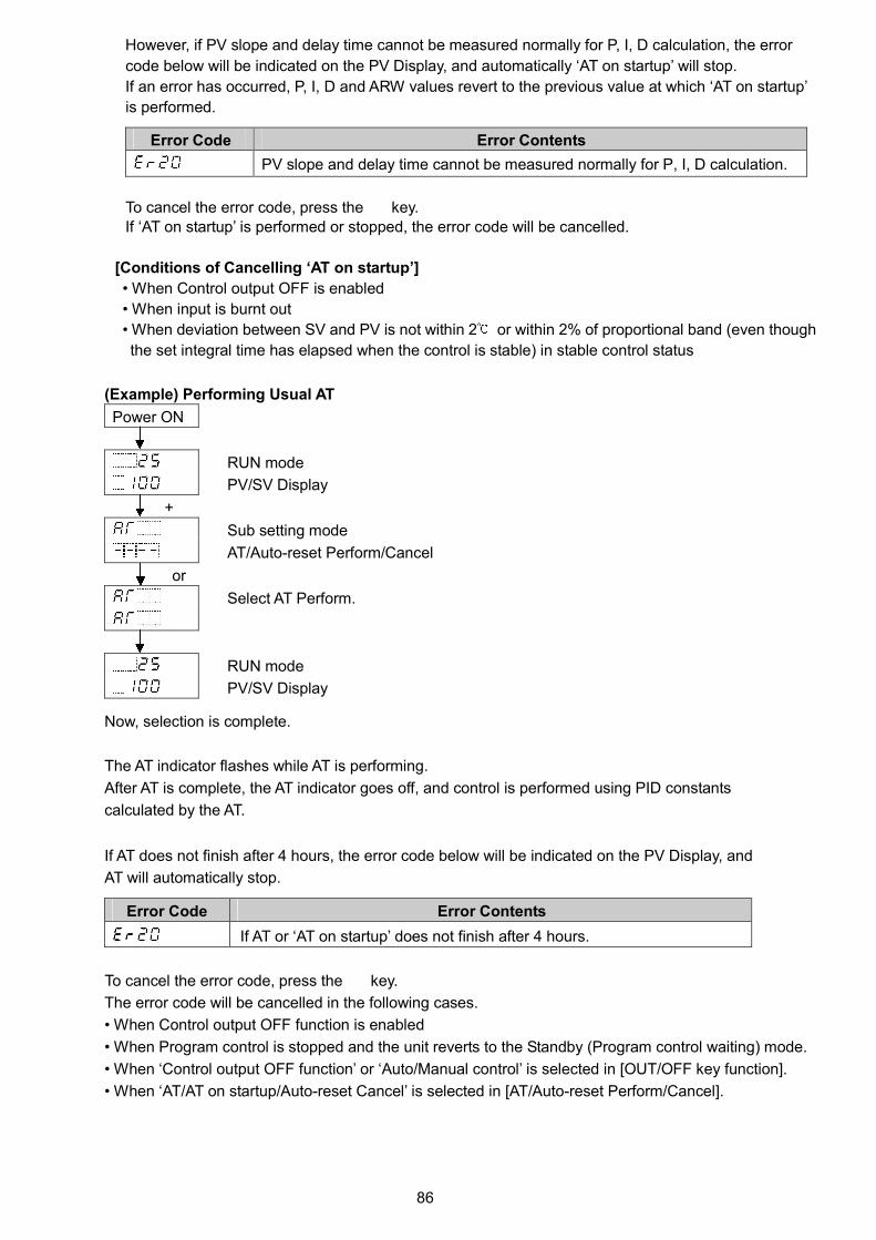
86
However, if PV slope and delay time cannot be measured normally for P, I, D calculation, the error
code below will be indicated on the PV Display, and automatically ‘AT on startup’ will stop.
If an error has occurred, P, I, D and ARW values revert to the previous value at which ‘AT on startup’
is performed.
Error Code Error Contents
PV slope and delay time cannot be measured normally for P, I, D calculation.
To cancel the error code, press the key.
If ‘AT on startup’ is performed or stopped, the error code will be cancelled.
[Conditions of Cancelling ‘AT on startup’]
• When Control output OFF is enabled
• When input is burnt out
• When deviation between SV and PV is not within 2 or within 2% of proportional band (even though
the set integral time has elapsed when the control is stable) in stable control status
(Example) Performing Usual AT
Power ON
RUN mode
PV/SV Display
+
Sub setting mode
AT/Auto-reset Perform/Cancel
or
Select AT Perform.
RUN mode
PV/SV Display
Now, selection is complete.
The AT indicator flashes while AT is performing.
After AT is complete, the AT indicator goes off, and control is performed using PID constants
calculated by the AT.
If AT does not finish after 4 hours, the error code below will be indicated on the PV Display, and
AT will automatically stop.
Error Code Error Contents
If AT or ‘AT on startup’ does not finish after 4 hours.
To cancel the error code, press the key.
The error code will be cancelled in the following cases.
• When Control output OFF function is enabled
• When Program control is stopped and the unit reverts to the Standby (Program control waiting) mode.
• When ‘Control output OFF function’ or ‘Auto/Manual control’ is selected in [OUT/OFF key function].
• When ‘AT/AT on startup/Auto-reset Cancel’ is selected in [AT/Auto-reset Perform/Cancel].

87
8.6 Performing Auto-reset
Notice• Auto-reset is cancelled in approximately 4 minutes. It cannot be cancelled while performing
this function.
• If input is burnt out, Auto-reset will be forced to stop.
Auto-reset is performed to correct the offset at the point at which PV indication is stabilized within
the proportional band during the PD control. Since the corrected value is internally memorized, it is
not necessary to perform the Auto-reset again as long as the process is the same.
However, when OUT1 proportional band (P) is set to 0 or 0.0, the corrected value is cleared to 0 (zero).
(Fig. 8.6-1)
(Example) Performing Auto-reset
Power ON
RUN mode
PV/SV Display
+
Sub setting mode
AT/Auto-reset Perform/Cancel
or
Select Auto-reset Perform.
RUN mode
PV/SV Display
Now, selection is complete.
The AT indicator flashes while Auto-reset is performing.
Auto-reset is completed in approximately 4 minutes.
After Auto-reset is complete, the AT indicator goes off, and control is performed
using the offset corrected value.
Auto-reset is performed.
Offset is corrected.
Offset span
Temperature
Time
SV

88
8.7 Performing Program Control
In Program control, SV changes as time elapses, and PV is controlled in order to reach each SV.
SV and time can be set for every step, and a maximum of 9 steps can be repeatedly controlled.
SV can be set as (Fig. 8.7-1).
(e.g.) Program control of electric furnaces in ceramic manufacture, food machinery, etc.
(Fig. 8.7-1)
Major functions of Program control are shown below.
Number of patterns and steps: 1 pattern; 9 steps
Wait function
While Program control is running, the program does not proceed to the next step
until the deviation between PV and SV enters SV Wait value at the end of step.
The PV Display flashes while the Wait function is working.
The Wait function is cancelled on the condition that:
• When program pattern is rising: PV is higher than SV- Wait value
• When program pattern is falling: PV is lower than SV+ Wait value
Step 1 2 3 4 5
: PV
: Program pattern
: Program pattern delayed by T due to the Wait function
(Fig. 8.7-2)
200
0
TT
If PV becomes higher than 190 , the waitfunction will be cancelled, proceeding to Step 2.
Wait value 10
As PV is not in the range of SV Wait value, the unitis in Wait status, and does not proceed to Step 2.The STEP indicator flashes during Wait action (T time).
Temperature
Time
Step

89
1
① ②
1:00 2:00
2
Program control Holding/Not holding
During Program control, progress of current step is suspended, and then
Fixed value control is performed using the SV from the point of suspension.
Program control Holding/Not holding can be selected in [Event input DI1/DI2 allocation].
Advance function
Interrupts current step while Program control is running, and proceeds to the beginning of the next
step.
By pressing the key for approx. 1 second during Program control, Advance function initiates.
Select this function in [Event input DI1/DI2 allocation].
Pattern end output
If Pattern end output is selected in [Event output EV1/EV2 allocation], pattern end output is turned
ON after Program control is finished, and the SV Display flashes .
By pressing the key for approx. 1 second, pattern end output is turned OFF, and the unit enters
Standby mode.
Step time unit
Step time unit can be selected: Hours:Minutes, Minutes:Seconds
Factory default value is Hours:Minutes.
Power Restore Action (Program control after power is restored)
If power fails during Program control, selects a status after the power is restored.
Factory default value is ‘Stops after power is restored’.
Power Restore Action Description
Stops after power is
restored.
Stops Program control, and returns to Standby (Program control
waiting) mode.
Continues after power is
restored. (*)
Continues (resumes) Program control.
Suspends after power is
restored. (*)
Suspends (on hold) current program, and performs Fixed value
control using the SV from the point of suspension.
Pressing the key cancels suspension, and Program control
resumes.
(*) Progressing time error when power is restored: 10 minutes
This controller saves internal status every 10 minutes after Program control starts.
Internal status is also saved when step is changed.
When power is restored, the unit starts from the last auto-save point.
(Fig. 8.7-3)
Step number
Step time
Auto-save point (●)
Saves internal data every
10 minutes based on
program control start time.
PV start is used. SV and time are
advanced to the remaining time 0:52,
and program control starts.
If power failure occurs at
remaining time 0:28,
control resumes at ① 0:32.
If power failure occurs at remaining time 1:45,
control resumes at ② 1:52.

90
Program start temperature
When Program control starts, it starts from the value set in [Program start temperature].
Factory default value is 0 .
Program control start type
One type can be selected: PV start, PVR start, SV start.
Factory default value is PV start.
Program control
start typeDescription
PV start When Program control starts, the SV and step time are advanced to the PV,
then Program control starts.
However, if [Program start temperature] at the time of Program control start is
higher than the PV (when PV start is initiated), then Program control will start
from the SV set in [Program start temperature].
PVR start In pattern repeating, the SV and step time are advanced to the PV, then the
Program control starts.
SV start Program control starts from the SV which has been set in [Program start
temperature].
[SV start] [PV/PVR start]
(Fig. 8.7-4) (Fig. 8.7-5)
Repeat function
When Program control is finished, control can be repeated from Step 1.
The user determines the number of repetitions.
Factory default value is 0 (zero).
Time
SV
100
1:00
Program control starts.
SV when Programcontrol starts
Time
SV
100
25
1:00
0:45
Program control starts from the PV
start point (measured value 25 ).
PV start point

91
Program control starts
1:00 2:00
200
0
0:30 1:00 2:00
300
Select ‘Program control’ in [OUT/OFF key function] in Engineering mode 1.
Factory default value is Control output OFF function.
Set the following items in Engineering mode 1:
Step time unit, Power restore action, Program start temperature,
Program control start type, Number of repetitions
Program pattern can be set in Main setting mode.
Example of program pattern setting
Step 1 2 3 4 5
SV ( ) 200 200 300 300 0
Time 1:00 2:00 0:30 1:00 2:00
Wait value ( ) 10 0 10 0 0
(Fig. 8.7-6)
In the above program pattern, control is performed at each step as follows.
Step 1: The SV gradually rises to 200 for 1 hour.
When step ends, Wait function works so that control cannot proceed to the next step until
PV reaches 190 when step ends.
Step 2: Fixed value control is performed to keep SV at 200 for 2 hours.
Step 3: Control is performed so that the SV gradually rises to 300 for 30 minutes.
When step is finished, Wait function works so that control cannot proceed to the next step
until PV reaches 290 .
Step 4: Fixed value control is performed to keep SV at 300 for 1 hour.
Step 5: Control is performed so that the SV gradually falls to 0 for 2 hours.

92
(Example) Selecting Program control and Setting program pattern of (Fig. 8.7-6)
Power ON
RUN mode
PV/SV Display
+ (3 sec)
Engineering mode 1
Set value lock
(Multiple times)
OUT/OFF key function
or
Select (Program control).
(Multiple times) or (3 sec)
RUN mode
Standby (Program control waiting) mode
Main setting mode
Step 1 SV
or
Set to 200 .
Step 1 time
or
Set to 1:00.
Step 1 wait value
or
Set to 10 .
Step 2 SV
or
Set to 200 .
Step 2 time
or
Set to 2:00.

93
Step 2 wait value
or
Set to 0 .
Step 3 SV
or
Set to 300
Step 3 time
or
Set to 0:30.
Step 3 wait value
or
Set to 10 .
Step 4 SV
or
Set to 300 .
Step 4 time
or
Set to 1:00.
Step 4 wait value
or
Set to 0 .
Step 5 SV
or
Set to 0 .

94
Step 5 time
or
Set to 2:00.
Step 5 wait value
or
Set to 0 .
(Multiple times) or (3 sec)
RUN mode
Standby (program control waiting) mode
Now, selection is complete.
Program control RUN
To perform Program control, press and hold the key for approx. 1 second in Standby (program
control waiting) mode.
Program control starts using the start type selected in [Program control start type].
While Wait function is working, the PV Display flashes.
Program control STOP
To stop Program control, press and hold the key for approx. 1 second during Program control.
Program control will stop, and the unit will revert to Standby (Program control waiting) mode.
Proceeding to the next step during Program control (Advance function)
By pressing the key for approx. 1 second during Program control, the performing step is
interrupted, proceeding to the next step. (Advance function)
While Wait function is working, the Wait function is cancelled, and proceeds to the next step.
If ‘ (Program control RUN/STOP)’ is selected in [Event input DI1 allocation], Program control
RUN/STOP can be switched by terminals 17-18 [DI1-COM]:
Signal edge action from OFF to ON / ON to OFF is engaged.
However, for the action when power is turned ON, Level action [ON (Closed) or OFF (Open)] is engaged.
17-18 [DI1-COM]:OFF (Open)Standby mode
Standby mode
17-18 [DI1-COM]:ON (Closed)Program control performs.
Program control RunProgram control Stop(Standby mode)
17-18 [DI1-COM]:OFF (Open)Program control stops(Standby mode).Terminals 17-18
[DI1-COM]OFF (Open) Program control performs when
“17-18 [DI1-COM]” changes fromOFF (Open) to ON (Closed)..
Program control stops (Standby mode)when “17-18 [DI1-COM]” changes fromON (Closed) to OFF (Open)..
Terminals 17-18[DI1-COM]ON (Closed)
Controller status
(Fig. 8.7-7)

95
8.8 Event Output EV1 Allocation
Selects Event output EV1 allocation.
There are 2 methods in selection of Event output EV1 allocation.
• Select in [Event output EV1 allocation] in Initial setting mode.
• Select in [Event output EV1 allocation] in Engineering mode 1.
Setting item [Event output EV1 allocation] in Initial setting mode corresponds to [Event output EV1
allocation] in Engineering mode 1.
Therefore, if one [Event output EV1 allocation] is changed, the other [Event output EV1 allocation]
will also be changed.
Factory default value is No event.
Selection item:
No event
Alarm output, High limit alarm
Alarm output, Low limit alarm
Alarm output, High/Low limits alarm
Alarm output, High/Low limits independentalarm
Alarm output, High/Low limit range alarm
Alarm output, High/Low limit range
independent alarm
Alarm output, Process high alarm
Alarm output, Process low alarm
Alarm output, High limit with standby alarm
Alarm output, Low limit with standby alarm
Alarm output, High/Low limits with standbyalarm
Alarm output, High/Low limits with standbyindependent alarm
Heater burnout alarm output
Loop break alarm output
Time signal output Turns OFF or ON during Program control,
by setting OFF time and ON time within
the step set in [Step number].
Output during AT Turns ON during AT.
Pattern end output Turns ON when Program control ends, and
remains ON until turned OFF by pressing
the key.
Output by communication command Turns OFF or ON by communication
command 00E4H during Serial
communication.
B0 EV1 output 0: OFF
1: ON
B1 EV2 output 0: OFF
1: ON

96
(Example) Selecting High limit alarm, and setting EV1 alarm value to 20
Power ON
RUN mode
PV/SV Display
+ (3 sec)
Initial setting mode
Input type
(3 times)
Event output EV1 allocation
or
Select (High limit alarm).
(2 times)
EV1 alarm value
or
Set to 20 .
(Multiple times) or (3 sec)
RUN mode
PV/SV Display
Now, settings are complete.

97
8.9 Indicating MV, Remaining Time (Program Control)
In Fixed value control and Program control, MV and remaining time are indicated.
To indicate MV, press and hold the key for approx. 3 seconds on the PV/SV Display.
The unit enters Monitor mode, and indicates MV.
While MV is indicating, the decimal point flashes.
While in Standby (Program control waiting) mode of Program control, the unit cannot move to Monitor
mode.
In Monitor mode, the following contents are switched every time the key is pressed.
Model Indicated Contents
Fixed value control Indicates MV, Set value memory number (in that order).BCS2
Program control Indicates MV, Remaining time, Step number (in that order).
Fixed value control Indicates only MV. (*)BCR2, BCD2
Program control Indicates MV, Remaining time (in that order). (*)
(*) For the BCR2, BCD2, Set value memory number (Fixed value control) and step number (Program control) are indicated on the
MEMO/STEP Display.
Indicating MV, Remaining time
Power ON
RUN mode
PV/SV Display
(3 sec)
Monitor mode
Indicates MV. (e.g.) MV: 7.2% (Decimal point flashes.)
Remaining time (Program control RUN)
(e.g.) Remaining time 0:30
Step number (Program control RUN) (BCS2)
(e.g.) Step 1
Set value memory number (Fixed value control) (BCS2)
(e.g.) Set value memory number 2
RUN mode
PV/SV Display

98
8.10 Items to be Initialized by Changing Settings
If settings are changed, the following items will be initialized.
: Initialized
X: Not initialized
Setting item to be
Item changed
to be initialized
Input TypeEvent output
EV1 allocation
Event output
EV2 allocation
Transmission
output
SV1 to SV9 X X X
Steps 1 to 9 wait value X X X
AT bias X X X
OUT1 proportional band X X X
Manual reset X X X
SV rise rate X X X
SV fall rate X X X
Scaling high limit X X X
Scaling low limit X X X
Program start temperature X X X
EV1 alarm value X X
EV1 high limit alarm value X X
Loop break alarm time X X X
Loop break alarm span X X X
SVTC bias X X X
Remote bias X X X
EV2 alarm value X X
EV2 high limit alarm value X X
Transmission output high limit
(Except MV transmission)
X X
Transmission output low limit
(Except MV transmission)
X X
OUT2 proportional band X X X
EV1 alarm value 0 Enabled/Disabled X X X
EV1 alarm hysteresis X X X
EV1 alarm delay time X X X
EV1 alarm Energized/De-energized X X X
EV2 alarm value 0 Enabled/Disabled X X X
EV2 alarm hysteresis X X X
EV2 alarm delay time X X X
EV2 alarm Energized/De-energized X X X
Sensor correction coefficient X X X
Sensor correction X X X
External setting input high limit X X X
External setting input low limit X X X

99
9. Attached Function9.1 Input Value Correction
Input value can be corrected in [Sensor correction coefficient] and [Sensor correction] in Engineering
mode 1.
In [Sensor correction coefficient], set the slope of temperature change.
In [Sensor correction], set the difference between temperatures before correction and after correction.
PV after input correction is expressed with the following formula.
PV after input correction = Current PV x Sensor correction coefficient + (Sensor correction value)
The following shows an example of input value correction using ‘Sensor correction coefficient’ and
‘Sensor correction value’.
(Fig.9.1-1)
(1) Select any 2 points of PV to be corrected, and determine the PV after correction.
PV before correction: 300 PV after correction: 340
PV before correction: 750 PV after correction: 700
(2) Calculate Sensor correction coefficient from Step (1).
(Y' – X') / (Y – X) = (700 – 340) / (750 - 300) = 0.8
(3) Enter a PV value of 300 using an mV generator or dial resistor.
(4) Set Step (2) value as a Sensor correction coefficient.
(5) Read the PV.
240 will be indicated.
(6) Calculate the sensor correction value.
Calculate the difference between ‘PV after correction’ and Step (5) PV.
340 – 240 = 100
(7) Set Step (6) value as a Sensor correction value.
(8) Enter an electromotive force or resistance value equivalent to 750 using an mV generator
or dial resistor.
(9) Read the PV, and confirm that 700 is indicated.
300
300
340
750
750
700
After correction
Before correction
Slope before correction
Slope after correction
Y
Y’
X’
X
Corrected from 750 to 700 .
Corrected from 300
to 340 .

100
(Example) Setting Sensor correction coefficient to 0.800, and Sensor correction to 100.0
Power ON
RUN mode
PV/SV Display
+ (3 sec)
Engineering mode 1
Set value lock
(Multiple times)
Sensor correction coefficient.
or
Set to 0.800.
Sensor correction
or
Set to 100.0 .
(Multiple times) or (3 sec)
RUN mode
PV/SV Display
Now, settings are complete.

101
9.2 Set Value Lock
Locks the set values to prevent setting errors.
Make a selection in [Set value lock] in Engineering mode 1.
The setting item to be locked depends on the selection.
Selection Item Change via Keypad Change via Software Communication
Unlock All set values can be changed. All set values can be changed.
Lock 1 None of the set values can be changed.
Lock 2 In Fixed value control, only SV and
Alarm value can be changed.
In Program control, Step SV, Step time
and Alarm value can be changed.
Lock 3 All set values can be changed.
Lock 4 None of the set values can be changed.
Lock 5 In Fixed value control, only SV and
Alarm value can be changed.
In Program control, Step SV, Step time
and Alarm value can be changed.
Setting items – except Input type,
Controller/Converter – can be changed
temporarily via software communication.
However, if power is turned ON again,
the setting values revert to the values
before Lock 3, 4 or 5 was selected.
(Example) Selecting Lock 2
Power ON
RUN mode
PV/SV Display
+ (3 sec)
Engineering mode 1
Set value lock
or
Select Lock 2.
(Multiple times) or (3 sec)
RUN mode
Converter
Now, selection is complete.

102
9.3 Control Output OFF Function
The control action and output of an instrument (or instruments) can be turned OFF without turning
OFF their power supplies using this function.
Select ‘Control output OFF function’ in [OUT/OFF key function] in Engineering mode 1.
Factory default value is Control output OFF function.
(Example) Selecting ‘Control output OFF function’, and ‘PV indication’ in [Indication when
control output OFF]
Power ON
RUN mode
PV/SV Display
+ (3 sec)
Engineering mode 1
Set value lock
(Multiple times)
Indication when control output OFF
or
Select (PV indication).
(Multiple times)
OUT/OFF key function
or
Select (Control output OFF function).
(Multiple times) or (3 sec)
RUN mode
PV/SV Display
Now, selection is complete.
To turn the control output OFF, press the key for approximately 1 second on the PV/SV Display.
PV is indicated on the PV Display. Indication differs depending on the selection in [Indication when
control output OFF].
Once the control output OFF function is enabled, the function cannot be cancelled even if the power
to the instrument is turned OFF and ON again.
To cancel the function, press the key again for approx. 1 second.
RUN mode (1 sec) Control output OFF
PV/SV Display [Unlit]

103
9.4 Switching Auto/Manual Control (Auto/Manual Control Function)
Control action can be switched from automatic to manual and vice versa.
When power to the controller is turned ON, Automatic or Manual control is selectable.
Select ’Auto/Manual control’ in [OUT/OFF key function] in Engineering mode 1.
Factory default value is Control output OFF function.
Select ‘Automatic control’ or ‘Manual control' in [Auto/Manual after power ON]
in Engineering mode 1.
Factory default value is Automatic control.
(Example) Selecting ‘Auto/Manual control ‘and ‘Manual control’ after power ON
Power ON
RUN mode
PV/SV Display
+ (3 sec)
Engineering mode 1
Set value lock
(Multiple times)
OUT/OFF key function
or
Select (Auto/Manual control).
Auto/Manual after power ON
or
Select (Manual control).
(Multiple times) or (3 sec)
RUN mode
PV/SV Display
Now, selection is complete.
By pressing the key in PV/SV Display for approx. 1 second, Auto/Manual control function can be
switched.
If control action is switched from automatic to manual and vice versa, balanceless-bumpless function
works to prevent a sudden change in the MV.
When automatic control is switched to manual control, MV flashes on the SV Display.
The MV on the SV Display can be increased or decreased by pressing the or key.
Data is saved 1 second after MV is changed, and manual control is performed.
When power is turned ON, control resumes using the previously saved MV (if manual control is
selected in [Auto/Manual after power ON]).
However, if (Auto/Manual control) is selected in [Event input DI1/DI2 allocation], then Event
input status has priority.
By pressing the key again for approx. 1 second, the unit reverts to automatic control.
RUN mode (1 sec) MV flashes (Manual control).
PV/SV Display
(Automatic control)
MV increases/decreases with
or key.

104
9.5 Using as a Converter
CautionInput/Output response time of this instrument is approx. 1 second.When using as a converter, the converter input will be 1 sec slower due to the response time.(In such cases please use a converter with input time slower than the response time above.)
This instrument can be used as a simplified converter.
Converts each input value (thermocouple, RTD, DC voltage and current inputs) to ‘4 to 20 mA DC’,
and outputs it.
When OUT1 is direct current output type, the controller can be used as a converter.
Select ‘Converter’ in [Controller/Converter] in Engineering mode 1.
Factory default value is ‘Controller’.
When this instrument is switched from controller to converter, values in the table below (Table 9.5-1)
are automatically set. The SV Display turns blank.
When this instrument is switched from converter to controller, the PV Display indicates for
1 second, and factory default values are set.
(Table 9.5-1)
Setting Item Set Value (or Selection)
SV1 (*1) Scaling low limit value
SV2 (*1)
(BCS2: EIW, EIT, EI options,
BCR2/BCD2: C5W, EIW, EIT, EI options)
Scaling low limit value
SV3 (*1)
(BCS2: EIW, EI options,
BCR2/BCD2: C5W, EIW, EIT, EI options)
Scaling low limit value
SV4 (*1)
(BCS2: EIW, EI options,
BCR2/BCD2: C5W, EIW, EIT, EI options)
Scaling low limit value
AT/Auto-reset Perform/Cancel (*2) AT/AT on startup/Auto-reset Cancel
OUT1 proportional band (*1) Scaling span
Integral time 0
Derivative time 0
Reset (*3) 0 (Initialized)
(Reset value, calculated by Auto-reset function)
OUT1 high limit 100
OUT1 low limit 0
OUT1 rate-of-change 0
OUT2 proportional band (*1) Scaling span
Direct/Reverse action Direct action
EV1/EV2 alarm value 0 Enabled/Disabled Disabled
EV1/EV2 alarm value 0 or Input range low limit value (Scaling low limitvalue)
EV1/EV2 high limit alarm value 0 or Input range low limit value (Scaling low limitvalue)
EV1/EV2 alarm hysteresis 1.0 (DC voltage, current input: The placement of
the decimal point follows the selection.)
EV1/EV2 alarm delay time 0
EV1/EV2 alarm Energized/De-energized Energized(*1) When input range is changed while this instrument is used as a converter, SV1 to SV4, OUT1 and OUT2 proportional bands
will be automatically set to values corresponding to the input range.
(*2) If “AT on startup” is successfully completed and “AT on startup Perform” has been still selected, “AT on startup” will be stopped
(AT/ AT on startup/Auto-reset Cancel).
(*3) The reset value calculated by Auto-reset function will be initialized.

105
Setting Item Set Value (or Selection)
Loop break alarm time 0
Loop break alarm span 0
Event input DI1 allocation(BCS2: EIW, EIT, EI options,
BCR2/BCD2: C5W, EIW, EIT, EI options)
No event
Event input DI2 allocation(BCS2: EIW, EI options, BCR2/BCD2: C5W, EIW, EIT, EI options)
No event
Event output EV1 allocation No event
Event output EV2 allocation (EV2, EV2+D options) No event
Remote/Local (EIT option) Local
Transmission output type (EIT option) PV transmission
Transmission output high limit (EIT option) Input range high limit
Transmission output low limit (EIT option) Input range low limit
SV rise rate 0
SV fall rate 0
OUT/OFF key function Control output OFF function
9.5.1 Selecting Converter Function
Power ON
RUN mode
PV/SV Display
+ (3 sec)
Initial setting mode
Input type
Select an input type with the or key.
Scaling high limit
Set a 100% output value which is indicated on the PV Display, using the or
key.
Scaling low limit
Set a 0% output value which is indicated on the PV Display, using the or key.
(Multiple times or 3 sec)
RUN mode
PV/SV Display
+ (3 sec)
Engineering mode 1
Set value lock
(Multiple times)
Controller/Converter
Available only when OUT1 is direct current output type.
or
Select (Converter).
RUN mode
[Unlit] Converter
Now, selection is complete.

106
9.5.2 Fine Adjustment of Converter Output (4 to 20 mA DC)
4 to 20 mA DC will be output corresponding to the input from Scaling low limit to Scaling high limit.
Fine adjustment range: 1/Scaling span
Fine Adjustment Method for Converter Output
Be sure to perform Zero side first in fine adjustment of converter output.
Perform Zero side adjustment in [Manual reset].
Perform Span side adjustment in [OUT1 proportional band].
(1) Adjust Zero side.
RUN mode (Converter)
[Unlit] Enter a value so that the scaling low limit value is indicated on the PV Display.
+
Sub setting mode
Select ‘AT/Auto-reset Perform/Cancel’.
(Multiple times)
Manual reset
Adjust a value with the or key so that the output value becomes
4 mA DC. The decreases the output, and the increases the output.
OUT1 high limit
If the output value is not 4 mA DC, return to [Manual reset] with the key,
and adjust again.
(Multiple times)
RUN mode (Converter)
[Unlit]
(2) Adjust Span side.
RUN mode (Converter)
[Unlit] Enter a value so that the scaling high limit value is indicated on the PV
Display.
+
Sub setting mode
Select ‘AT/Auto-reset Perform/Cancel’.
OUT1 proportional band
Adjust the value with or key so that the output value becomes 20
mA DC. The decreases the output, and the increases the output.
Integral time
If the output value is not 20 mA DC, return to [OUT1 proportional band] with
the key, and adjust again.
(Multiple times)
RUN mode (Converter)
[Unlit]
(3) Repeat (1) and (2) until the correct value is output.
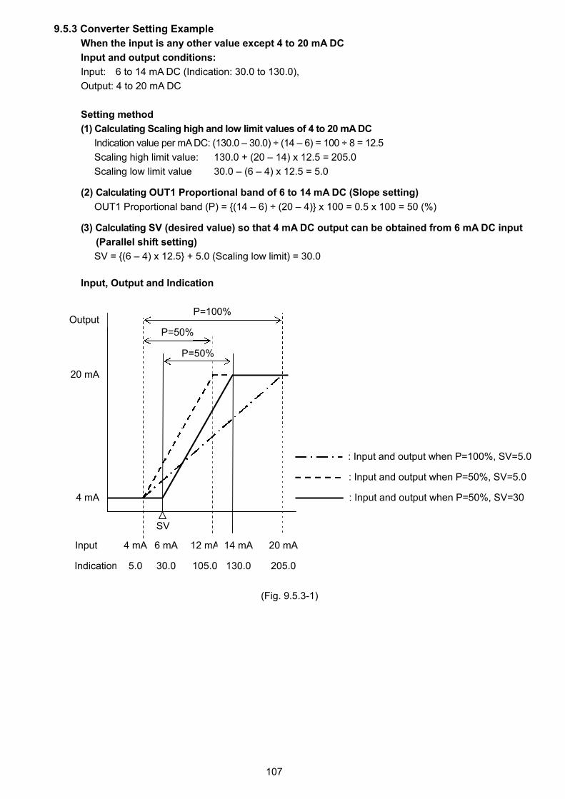
107
9.5.3 Converter Setting Example
When the input is any other value except 4 to 20 mA DC
Input and output conditions:
Input: 6 to 14 mA DC (Indication: 30.0 to 130.0),
Output: 4 to 20 mA DC
Setting method
(1) Calculating Scaling high and low limit values of 4 to 20 mA DC
Indication value per mA DC: (130.0 – 30.0) ÷ (14 – 6) = 100 ÷ 8 = 12.5
Scaling high limit value: 130.0 + (20 – 14) x 12.5 = 205.0
Scaling low limit value 30.0 – (6 – 4) x 12.5 = 5.0
(2) Calculating OUT1 Proportional band of 6 to 14 mA DC (Slope setting)
OUT1 Proportional band (P) = {(14 – 6) ÷ (20 – 4)} x 100 = 0.5 x 100 = 50 (%)
(3) Calculating SV (desired value) so that 4 mA DC output can be obtained from 6 mA DC input
(Parallel shift setting)
SV = {(6 – 4) x 12.5} + 5.0 (Scaling low limit) = 30.0
Input, Output and Indication
(Fig. 9.5.3-1)
P=100%
P=50%
P=50%
: Input and output when P=100%, SV=5.0
: Input and output when P=50%, SV=30
Output
20 mA
4 mA
SV
Input 4 mA 6 mA 12 mA 14 mA 20 mA
Indication 5.0 30.0 105.0 130.0 205.0
: Input and output when P=50%, SV=5.0

108
9.6 Clearing Data
If data is cleared, data will revert to factory default values.
To clear data, press and hold , , , (in that order) together for approx. 3 seconds
on the PV/SV Display.
The unit enters [Data clear Yes/No] mode.
Select ‘Yes’, and press the key. Data will be cleared.
While data is clearing, is indicated on the PV Display.
Clearing Data
Power ON
RUN mode
PV/SV Display
+ + + (3 sec)
Data clear Yes/No
or
Select (Yes).
Data is clearing.
After data is cleared, the unit automatically reverts to the PV/SV Display.
RUN mode
PV/SV Display

109
10. Action Explanation10.1 OUT1 Action
: Turns ON (lit) or OFF (unlit).
BCR2, BCD2: OUT1 terminal numbers become 15, 16.
10.2 OUT1 ON/OFF Control Action
: Turns ON (lit) or OFF (unlit).
BCR2, BCD2: OUT1 terminal numbers become 15, 16.
Reverse (Heating) action Direct (Cooling) action
Control
action
Cycle action is performedaccording to deviation.
Relay contact
output
Non-contactvoltage output
Changes continuouslyaccording to deviation.
Direct currentoutput
Indicator
(O1) GreenLit Unlit
ON
OFF
SV
Proportional band
ON
OFF
0 V DC 0/12 V DC12 V DC
+
20 mA DC 20 to 4 mA DC 4 to 20 mA DC
Proportional band
Lit
0 V DC 12 V DC12/0 V DC
20 mA DC4 mA DC
Cycle action is performedaccording to deviation.
Cycle action is performedaccording to deviation.
Cycle action is performedaccording to deviation.
Changes continuouslyaccording to deviation.
+ + + + +
++++++
Unlit
4 mA DC
8
7
8
7
8
7
8
7
8
7
8
7
8
7
8
7
8
7
8
7
8
7
8
7
8
7
8
7
8
7
8
7
8
7
8
7
SV
Reverse (Heating) action Direct (Cooling) action
Control
action
Relay contactoutput
Non-contactvoltage output
Direct currentoutput
Indicator(O1) Green
0 V DC12 V DC
+
4 mA DC
LitUnlit
ON
OFF
SV
ON
OFF
Hysteresis Hysteresis
0 V DC 12 V DC
4 mA DC 20 mA DC
UnlitLit
20 mA DC
+
+ +
+
+
+
+
8
7
8
7
8
7
8
7
8
7
8
7
8
7
8
7
8
7
8
7
8
7
8
7
SV

110
Load current
UnlitLit
ON
OFFHeater burnout
alarm action
Output
Indicator
3
4
3
4
Small Large
Heater burnout alarm value
10.3 Heater Burnout Alarm Action
BCS2: Event output 1 terminal numbers become 3, 4. Event output 2 terminal numbers become 5, 6.
BCR2, BCD2: Event output 1 terminal numbers become 17, 18. Event output 2 terminal numbers become 19, 20.
If EV2+D option is added: Event output 2 terminal numbers become 6, 7.

111
OFF
ON
SV SV
OFF
ON
OFF
ON
OFF
ON
OFF
ON
OFF
ON
OFF
ON
SV
SV
OFF
ON
Process high alarm Process low alarm
High limit alarm Low limit alarm
High/ Low limit range alarm High/Low limit range independent alarm
High/Low limits alarm High/Low limits independent alarm
Alarmaction
Alarmoutput
Alarmaction
Alarmoutput
Alarmaction
Alarmoutput
Alarmaction
Alarmoutput
EV1 hysteresis
EV1 value SV
+side
- side
+side
- side
SV
EV1 value
EV1 value EV1 value
EV1 value EV1 value
EV1 hysteresis
EV1 hysteresisEV1 hysteresis
EV1 hysteresis EV1 hysteresis
-EV1 value +EV1 value -EV1 value +EV1 value
EV1 hysteresis EV1 hysteresis
EV1 low limit value EV1 high limit value
EV1 high limit valueEV1 low limit value
10.4 Alarm Action

112
High limit with standby alarm
OFF
ON
SV SV
OFF
ON
OFF
ON
OFF
ON
SV
Low limit with standby alarm
High/Low limits with standby alarm H/L limits with standby independent alarm
Alarmaction
Alarmoutput
Alarmaction
Alarmoutput
SV
+ side
- side
+side
- side
-EV1 value -EV1 value+EV1 value +EV1 value
EV1 hysteresis
EV1 hysteresis EV1 hysteresis
EV1 hysteresis
EV1 value EV1 value EV1 low limit value EV1 high limit value
• EV1 value, EV1 high limit value, and EV1 hysteresis represent EV1 alarm value,
EV1 high limit alarm value and EV1 alarm hysteresis respectively.
For EV2, read “EV2” for “EV1”.
• EV1 indicator lights when Event output 1 terminals 3 and 4 are ON, and
goes off when their output terminals 3 and 4 are OFF.
EV2 indicator lights when Event output 2 terminals 5 and 6 are ON, and
goes off when their output terminals 5 and 6 are OFF.
• BCR2, BCD2: Event output 1 terminal numbers become 17, 18.
Event output 2 terminal numbers become 19, 20.
If EV2+D option is added: Event output 2 terminal numbers become 6, 7.
: Event output 1 terminals 3 and 4: ON (closed).
: Event output 1 terminals 3 and 4: ON (closed) or OFF (open).
: Event output 1 terminals 3 and 4: OFF (open).
: Alarm output is in Standby.

113
10.5 OUT2 (Heating/Cooling Control) Action
: Turns ON (lit) or OFF (unlit).
: Represents Heating control action.
: Represents Cooling control action.
• BCR2, BCD2: OUT1 terminal numbers become 15, 16.
OUT2 terminal numbers become 19, 20.
OFF
ON
SV
OFF
ON
888
777
7+
8-
12V DC
7+
8-
12/0 V DC
7+
8-
0 V DC
7+
8-
20 mA DC
7+
8-
7+
8-
4 mA DC
555
666
5+
6-
12V DC
5+
6-
0 V DC
5+
6-
0/12V DC
5+
6-
20 mA DC
5+
6-
4 mA DC
5+
6-
Direct currentoutput
(OUT2)
Non- contactvoltage output
(OUT2)
Relay contactoutput
(OUT2)
Indicator (O1)
Indicator (O2)
Lit
Unlit
Cycle action is performedaccording to deviation
Changes continuouslyaccording to deviation.
Cycle action is performedaccording to deviation
Changes continuouslyaccording to deviation.
Cycle action is performedaccording to deviation
Cycle action is performedaccording to deviation
Controlaction
Heating P-band (Cooling P-band)
(Coolingcontrol)
Relay contactoutput
(OUT1)
Non- contactvoltage output
(OUT1)
Direct currentoutput
(OUT1)
Unlit
Lit
Heatingcontrol
4 to 20 mA DC
20 to 4 mA DC

114
10.6 OUT2 (Heating/Cooling Control) Action (When Setting Dead Band)
: Turns ON (lit) or OFF (unlit).
: Represents Heating control action.
: Represents Cooling control action.
• BCR2, BCD2: OUT1 terminal numbers become 15, 16.
OUT2 terminal numbers become 19, 20.
OFF
ON
SV
OFF
ON
7+
8-
12V DC
7+
8-
12/0 V DC
7+
8-
0 V DC
7+
8-
20 mA DC
7+
8-
7+
8-
4 mA DC
888
777
6 6 6
Indicator (O1)
Unlit
5 5 5
5+
6-
12V DC
5+
6-
0/12V DC
5+
6-
0 V DC
5+
6-
20 mA DC
5+
6-
5+
6-
4 mA DC
Controlaction
Cycle action is performedaccording to deviation
Cycle action is performedaccording to deviation
20 to 4 mA DC
Changes continuouslyaccording to deviation.
Cycle action is performedaccording to deviation
Cycle action is performedaccording to deviation
4 to 20 mA DC
Changes continuouslyAccording to deviation.
Heatingcontrol
(CoolingControl)
Heating P-band (Cooling P-band)Dead band
Lit
Lit
Unlit
Indicator (O2)
Relay contactoutput
(OUT2)
Non- contactvoltage output
(OUT2)
Direct currentoutput
(OUT2)
Direct currentoutput
(OUT1)
Non- contactvoltage output
(OUT1)
Relay contactoutput
(OUT1)
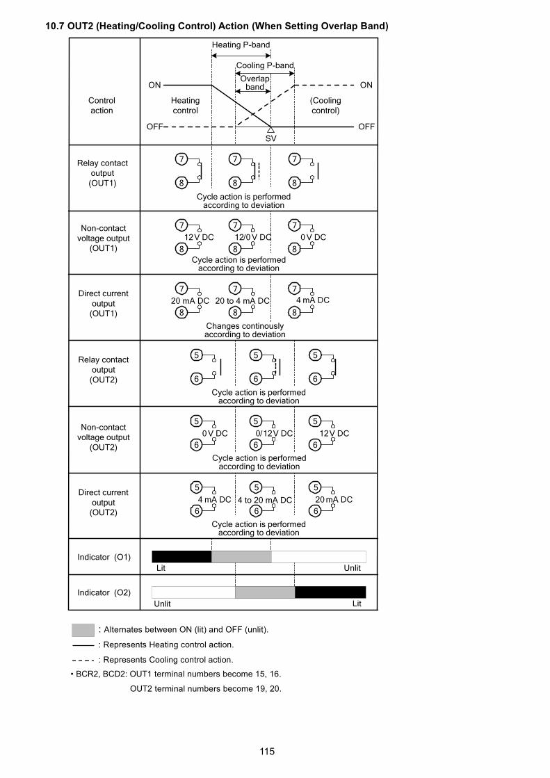
115
10.7 OUT2 (Heating/Cooling Control) Action (When Setting Overlap Band)
: Alternates between ON (lit) and OFF (unlit).
: Represents Heating control action.
: Represents Cooling control action.
• BCR2, BCD2: OUT1 terminal numbers become 15, 16.
OUT2 terminal numbers become 19, 20.
OFF
ON
SV
OFF
ON
888
777
5 5 5
6 6 6
5 5 5
6 6 6
888
777
888
777
12V DC 12/0 V DC 0 V DC
4 mA DC
4 mA DC 20 mA DC
5 5 5
6 6 6
0 V DC 0/12V DC 12V DC
Indicator (O1)
Heating P-band
Heatingcontrol
(Coolingcontrol)
Cooling P-band
Overlapband
Cycle action is performedaccording to deviation
Cycle action is performedaccording to deviation
Changes continouslyaccording to deviation
20 to 4 mA DC20 mA DC
Cycle action is performedaccording to deviation
Cycle action is performedaccording to deviation
Cycle action is performedaccording to deviation
4 to 20 mA DC
Lit Unlit
LitUnlit
Indicator (O2)
Non-contactvoltage output
(OUT2)
Direct currentoutput
(OUT2)
Relay contactoutput
(OUT2)
Direct currentoutput
(OUT1)
Non-contactvoltage output
(OUT1)
Relay contactoutput
(OUT1)
Controlaction

116
11. Specifications11.1 Standard Specifications
Rating
Input Scale Range Resolution
-200 to 1370 -328 to 2498 1 ( )K
-200.0 to 400.0 -328.0 to 752.0 0.1 ( )
J -200 to 1000 -328 to 1832 1 ( )
R 0 to 1760 32 to 3200 1 ( )
S 0 to 1760 32 to 3200 1 ( )
B 0 to 1820 32 to 3308 1 ( )
E -200 to 800 -328 to 1472 1 ( )
T -200.0 to 400.0 -328.0 to 752.0 0.1 ( )
N -200 to 1300 -328 to 2372 1 ( )
PL- 0 to 1390 32 to 2534 1 ( )
C(W/Re5-26) 0 to 2315 32 to 4199 1 ( )
-200.0 to 850.0 -328.0 to 1562.0 0.1 ( )Pt100
-200 to 850 -328 to 1562 1 ( )
-200.0 to 500.0 -328.0 to 932.0 0.1 ( )JPt100
-200 to 500 -328 to 932 1 ( )
4 to 20 mA -2000 to 10000 (*) 1
0 to 20 mA -2000 to 10000 (*) 1
0 to 1 V -2000 to 10000 (*) 1
0 to 5 V -2000 to 10000 (*) 1
1 to 5 V -2000 to 10000 (*) 1
0 to 10 V -2000 to 10000 (*) 1
Rated scale
(*) Scaling and decimal point place selection are possible.
Thermocouple K, J, R, S, B, E, T, N, PL- , C(W/Re5-26)
External resistance: 100 max.
However, for B input, External resistance: 40 max.
RTD Pt100, JPt100 3-wire type
Allowable input lead wire resistance: 10 max. per wire
Direct current 0 to 20 mA DC, 4 to 20 mA DC
Input impedance: 50
Allowable input current: 50 mA max.
0 to 1 V DC
Input impedance: 1 M min.
Allowable input voltage: 5 V DC max.
Allowable signal source resistance: 2 k max.
Input
DC voltage
0 to 5 V DC, 1 to 5 V DC, 0 to 10 V DC
Input impedance: 100 k min.
Allowable input voltage: 15 V DC max.
Allowable signal source resistance: 100 max.
BC 2 00- 100 to 240 V AC 50/60 HzPowersupplyvoltage
BC 2 10- 24 V AC/DC 50/60 Hz
BC 2 00- 85 to 264 V ACAllowablevoltagefluctuation
BC 2 10- 20 to 28 V AC/DC

117
General Structure
BCS2 48 x 48 x 68 mm (W x H x D) (Depth of control panel interior: 60 mm)
BCR2 48 x 96 x 68 mm (W x H x D) (Depth of control panel interior: 60 mm)
External
dimensions
BCD2 96 x 96 x 68 mm (W x H x D) (Depth of control panel interior: 60 mm)
Mounting Flush
Case Flame-resistant resin, Black
Front panel Membrane sheet
Drip-proof/Dust-proof Front panel: IP66, Rear case: IP20, Terminal section: IP00
EN EN61010-1 (Pollution degree 2, Overvoltage category )Standards
EC
(EMC
directive)
EMI: EN61326
Electric-field strength of radiated disturbance: EN55001 Group 1
Class A
Terminal noise voltage: EN55011 Group 1 Class A
EMS: EN61326
Indicates PV.7-segment Red LED display
BCS2 Character size: 12.4 x 5.8 mm (H x W)
BCR2 Character size: 14 x 5.8 mm (H x W)
PV Display
BCD2 Character size: 24 x 11 mm (H x W)
Indicates SV.7-segment Green LED display
BCS2 Character size: 8.8 x 3.9 mm (H x W)
BCR2 Character size: 14 x 5.8 mm (H x W)
SV Display
BCD2 Character size: 14 x 7 mm (H x W)
Indicates Set value memory number (Fixed value control) or Stepnumber (Program control).7-segment Green LED display
BCR2 Character size: 14 x 5.8 mm (H x W)
MEMO/STEP
Display
(BCR2,
BCD2)BCD2 Character size: 14 x 7 mm (H x W)
O1 (Green) Lit when control output OUT1 is ON.For direct current output type, flashes correspondingto the MV in 125 ms cycles.
O2 (Yellow) Lit when control output OUT2 (EV2, DS, DA, EV2+Doptions) is ON.For direct current output type (DA, EV2+DA options),flashes corresponding to the MV in 125 ms cycles.
EV1 (Red) Lit when Event output 1 is ON.
EV2 (Red) Lit when Event output 2 (EV2, EV2+D options) isON.Unlit if (Heating/Cooling control relay contactoutput) is selected in [Event output EV2 allocation].
AT (Yellow) Flashes while AT, ‘AT on startup’ or Auto-reset isperforming.
R/L (Yellow) Lit during Remote action from Remote/Localswitching (EIT option).
T/R (Yellow) Lit during Serial communication (C5W, C5 options) TX(transmitting) output.
MEMO(Yellow)
Lit when Set value memory number (Fixed valuecontrol) is indicated.(BCR2, BCD2)
Indication
structure
Action
indicators
STEP(Green)
Lit when a step number (Program control) is indicated.(BCR2, BCD2)

118
Terminal arrangement Refer to ‘Terminal arrangement’. (p.19)
Console connector By connecting to the tool cable (CMD-001, sold separately), the
following operations can be conducted from an external computer using
the Console software SWC-BCx01M.
• Reading and setting of SV, PID and various set values
• Reading of PV and action status • Function change
Setting Structure
UP key Increases the numeric value.
By pressing this key for 1 second during Program control, the performing
step is interrupted, proceeding to the beginning of the next step.
(Advance function)
DOWN key Decreases the numeric value.
MODE key Selects a setting mode, or registers the set data.
By pressing this key for 3 seconds during RUN mode, the unit enters
Monitor mode.
The following function can be selected in [OUT/OFF key function].
Selection Item Action
Control output OFF function Turns the control output ON or OFF.
Auto/Manual control Switches the Auto/Manual control.
Function
key
OUT/OFF key
Program control Starts/Stops the Program control.
Indication Performance
Basic accuracy At ambient temperature 23 (for a single unit mounting)
Thermocouple Within 0.2% of each input span 1 digit
However R, S inputs, 0 to 200 (32 to 392 ): Within 6 (12 )
B input, 0 to 300 (0 to 572 ): Accuracy is not guaranteed.
K, J, E, T, N inputs, Less than 0 (32 ): Within 0.4% of input
span 1 digit
RTD Within 0.1% of each input span 1 digit
Direct current,DC voltage
Within 0.2% of each input span 1 digit
Effect of ambient temperature Within 50 ppm/ of each input span
Input sampling period 125 ms
Time accuracy Within 1.0% of setting time
Control Performance
Control action • PID control (with AT function)
• PI control: When derivative time is set to 0
• PD control (with Auto-reset, Manual reset function):
When integral time is set to 0
• P control (with Auto-reset, Manual reset function):
When derivative time and integral time are set to 0.
• ON/OFF control: When proportional band is set to 0 (or 0.0)
OUT1
proportional
band
Thermocouple, RTD inputs without decimal point: 0 to input span
Thermocouple, RTD inputs with decimal point: 0.0 to input span
Direct current, voltage inputs: 0.0 to 1000.0%
Integral time 0 to 3600 sec
Derivative time 0 to 1800 sec
OUT1 propor-tional cycle
0.5, or 1 to 120 sec
ARW 0 to 100%

119
Manual reset Proportional band value
OUT1 ON/OFF
hysteresis
Thermocouple, RTD inputs: 0.1 to 1000.0 ( )
Direct current, voltage inputs: 1 to 10000 (The placement of the decimal
point follows the selection.)
OUT1 high limit,OUT1 low limit
0 to 100% (Direct current output type: -5 to 105%)
Relay contact
1a
Control capacity: 3 A 250 V AC (resistive load)
1 A 250 V AC (inductive load cos =0.4)
Electrical life: 100,000 cycles
Minimum applicable load: 10 mA 5 V DC
Non-contactvoltage(For SSR drive)
12 V DC 15%
Max 40 mA (short circuit protected)
Control
output
Direct current 4 to 20 mA DC
Resolution: 12000
Load resistance: Max. 550
Standard Function
EV1 output The output is turned ON or OFF depending on the conditions selected in
[Event output EV1 allocation].
Relay contact 1a Control capacity: 3 A 250 V AC (resistive load)
1 A 250 V AC (inductive load cos =0.4)
Electrical life: 100,000 cycles
Minimum applicable load: 10 mA 5 V DC
Alarm action When an alarm type and Energized action are selected in [Event output
EV1 allocation] or [Event output EV2 allocation]: The alarm action point
is set by deviation from the SV (excluding Process alarm) and if PV
goes outside the range, alarm output is turned ON or OFF (High/Low
limit range alarm).
When De-energized action is selected, alarm is activated conversely.
Type High limit alarm, Low limit alarm, High/Low limits alarm, High/Low limits
independent alarm, High/Low limit range alarm, High/Low limit range
independent alarm, Process high alarm, Process low alarm, High limit
with standby alarm, Low limit with standby alarm, High/Low limits with
standby alarm, High/Low limits with standby independent alarm
Energized/De-energized action are applied to the above alarms, totaling
24 alarm types. No alarm action can also be selected.
Action ON/OFF action
Hysteresis Thermocouple, RTD inputs: 0.1 to 1000.0 ( )Direct current, voltage inputs: 1 to 10000 (The placement of the decimal
point follows the selection.)
Output EV1 output or EV2 output for which Alarm output (001 to 012) is
selected in [Event output EV1/EV2 allocation].
Alarm value 0
Enabled/
Disabled
If ‘Enabled’ is selected in [Alarm value 0 Enabled/Disabled], the
following alarm type activates even if alarm value is set to 0 (zero):
High limit alarm, Low limit alarm, High/Low limits alarm,High/Low limits
independent alarm, High/Low limit range alarm, High/Low limit range
independent alarm, High limit with standby alarm, Low limit with standby
alarm, High/Low limits with standby alarm, High/Low limits with standby
independent alarm.
Loop break alarm Detects heater burnout, sensor burnout and actuator trouble.
Event output EV1 or Event output EV2 for which Loop break alarm (014)
is selected in [Event output EV1/EV2 allocation].

120
If ‘Converter’ is selected in [Controller/Converter], this instrument can
be used as a converter. The following items are automatically set.
Setting Item Values or Selection
SV1 Scaling low limit value
SV2
(BCS2: EIW, EIT, EI options,
BCR2/BCD2: C5W, EIW, EIT, EI options)
Scaling low limit value
SV3
(BCS2: EIW, EI options,
BCR2/BCD2: C5W, EIW, EIT, EI options)
Scaling low limit value
SV4
(BCS2: EIW, EI options,
BCR2/BCD2: C5W, EIW, EIT, EI options)
Scaling low limit value
AT/Auto-reset Perform/Cancel AT/AT on startup/Auto-reset Cancel
OUT1 proportional band Scaling span
Integral time 0
Derivative time 0
Reset 0 (Initialized) (Reset value calculatedby Auto-reset function)
OUT1 high limit 100
OUT1 low limit 0
OUT1 rate-of-change 0
OUT2 proportional band Scaling span
Direct/Reverse action Direct action
EV1/EV2 alarm value 0
Enabled/Disabled
Disabled
EV1/EV2 alarm value 0 or Input range low limit value (Scaling
low limit value)
EV1/EV2 high limit alarm value 0 or Input range low limit value (Scaling
low limit value)
EV1/EV2 alarm hysteresis 1.0 (DC voltage, current inputs: The
placement of the decimal point follows
the selection.)
EV1/EV2 alarm delay time 0
EV1/EV2 alarm Energized/
De-energized
Energized
Loop break alarm time 0
Loop break alarm span 0
Event input DI1 allocation
(BCS2: EIW, EIT, EI options,
BCR2/BCD2: C5W, EIW, EIT, EI options)
000: No event
Event input DI2 allocation
(BCS2: EIW, EI option,
BCR2/BCD2: C5W, EIW, EIT, EI options)
000: No event
Event output EV1 allocation 000: No event
Event output EV2 allocation
(EV2, EV2+D options)
000: No event
Simplified converter
function
Remote/Local(EIT option)
Local

121
Transmission output type(EIT option)
PV transmission
Transmission output high limit(EIT option)
Input range high limit
Transmission output low limit(EIT option)
Input range low limit
SV rise rate 0
SV fall rate 0
OUT/OFF key function Control output OFF
4 to 20 mA DCLoad resistance: Max 550
Insulation, Dielectric Strength
Circuit insulation
configuration
BCS2
When the C5W or C5 option is ordered.
When the EIW, EI or W option is ordered.
1POWER
SUPPLY2
EV1
3
4
EV2OUT2
5
6
CT1CT2
CPU
RS-485
OUT1
7
8
TCRTD
DC
9
Electrically insulated
: When C5W option is ordered.P24
5
6
11
10
12
14
13
15
17
16
18
1POWER
SUPPLY2
EV1
3
4
EV2OUT2
5
6
CT1CT2
CPU
DI1DI2
OUT1
7
8
TCRTD
DC
9
P24
5
6
17
16
18
14
13
15
11
10
12
Electrically insulated
: When W option is ordered.
: When EI option is ordered.

122
Circuit insulation
configuration
When the EIT option is ordered.
When OUT1 is a non-contact voltage output or direct current output
type, and when OUT2 is a non-contact voltage output or direct current
output type, OUT1 is not electrically insulated from OUT2.
Insulation resistance: 10 M min., at 500 V DC
BCR2, BCD2
When the C5W or C5 option is ordered.
1POWER
SUPPLY2
EV1
3
4
EV2OUT2
5
6
CT1
CPU
EXTCONT
OUT1
7
8
TCRTD
DC
9
TA
P24
5
6
17
16
18
14
13
15
11
10
12
Electrically insulated
POWERSUPPLY
EV1
EV2OUT2
P24
CT1CT2
CPU
OUT1
TCRTDDC
RS-485
17
16
18
19
20
19
20
14
13
15
22
21
23
24
2
1
3
8 9 10 11 12 10 11 12
DI1DI2
RS-485
Electrically insulated
: When C5W option is ordered.

123
Circuit insulation
configuration
When the EIW or W option is ordered.
When the EIT or EI option is ordered.
When EV2+D option and EIT option are added simultaneously, EV2 terminal numbers become
6 and 7, and OUT2 terminal numbers become 19 and 20.
When OUT1 is a non-contact voltage output or direct current outputtype, and when OUT2 is a non-contact voltage output or direct currentoutput type, OUT1 is not electrically insulated from OUT2.Insulation resistance: 10 M min., at 500 V DC
Dielectric strength Between input terminal and power terminal: 1.5 kV AC for 1 minuteBetween output terminal and power terminal: 1.5 kV AC for 1 minuteBetween output terminal (P24) and power terminal: 500 V AC for 1 minute
POWERSUPPLY
EV1
EV2OUT2
P24
EXTCONT
CPU
OUT1
TCRTDDC
TA
17
16
18
19
20
19
20
14
13
15
22
21
23
24
4
5
8 9 12 6 7
DI1DI2
Electrically insulated
: When EIT option is ordered.
POWERSUPPLY
EV1
EV2OUT2
P24
CT1CT2
CPU
OUT1
TCRTDDC
17
16
18
19
20
19
20
14
13
15
22
21
23
24
2
1
3
8 9 12
DI1DI2
: When EIW option is ordered.
Electrically insulated

124
Power consumption 100 to 240 V AC Approx. 8 VA max. (When the maximum number of
options are added: Approx. 11 VA max.)
24 V AC Approx. 5 VA max. (When the maximum number of
options are added: Approx. 8 VA max.)
24 V DC Approx. 5 W max. (When the maximum number of
options are added: Approx. 8 W max.)
Rush current 100 to 240 V AC Max. 14 to 34 A
24 V AC Max. 34 A
24 V DC Max. 34 A
Ambient temperature -10 to 55 (Non-condensing, No icing)
Ambient humidity 35 to 85 %RH (Non-condensing)
Weight BCS2 Approx. 110 g
BCR2 Approx. 160 g
BCD2 Approx. 220 g
Accessories included Mounting frame: 1 piece (BCS2)
Screw type mounting bracket: 1 set (BCR2, BCD2)
Instruction manual (excerpt): 1 copy
Accessories sold
separately
Terminal cover
CT (Current transformer):
CTL-6S (For Heater burnout alarm 20 A)
CTL-12-S36-10L1U (For Heater burnout alarm 100 A)
Tool cable CMD-001
Environmental specification RoHS directive compliant
Attached FunctionsSensor correctioncoefficient
Sets slope of input value from a sensor.
Sensor correction Corrects the input value from a sensor.
Set value lock Locks the set values to prevent setting errors.
Auto/Manual control
switching
Switches Auto/Manual control.
In Manual control, sets MV with the or key.
SV ramp function When the SV is adjusted, it approaches the new SV by the preset
rate-of-change. Set SV rise rate and SV fall rate respectively.
SV Rise/Fall rate start type When control output is turned from OFF to ON, or switched from Manual
to Automatic control, SV start or PV start can be selected for SV rise rate
or SV fall rate action.
Program control 1 pattern; 9 stepsPower failurecountermeasure
The setting data is backed up in the non-volatile IC memory.
Self-diagnosis The CPU is monitored by a watchdog timer, and if an abnormal status
occurs, the controller is switched to warm-up status, turning all outputs
OFF.
Automatic cold junction
temperature compensation
This detects the temperature at the connecting terminal between the
thermocouple and the instrument, and always maintains it at the same
status as if the reference junction location temperature was at 0 (32 ).
Thermocouple [Input range low limit value – 50 (100 )] to
[Input range high limit value + 50 (100 )]
RTD [Input range low limit value – (Input span x 1%)] to
[Input range high limit value + 50 (100 )]
Indication
range,
Control
range
DC voltage,
Direct current
[Scaling low limit value – (Scaling span x 1%)] to
[Scaling high limit value + (Scaling span x 10%)]
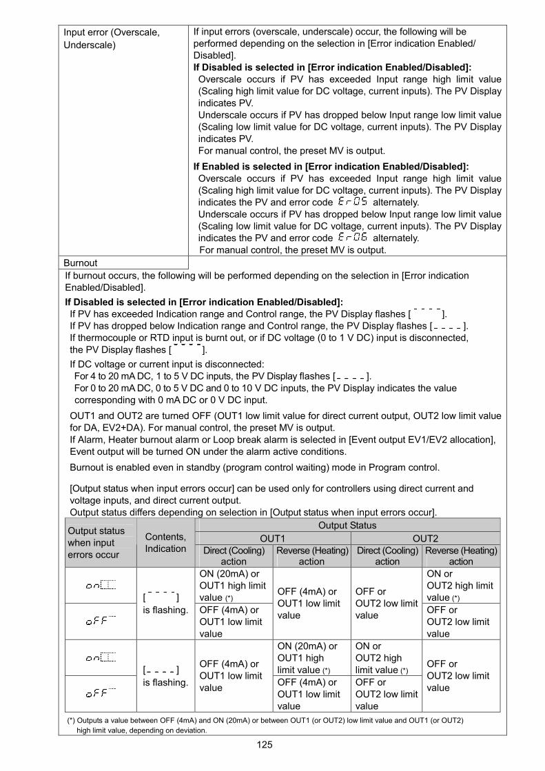
125
Input error (Overscale,
Underscale)
If input errors (overscale, underscale) occur, the following will beperformed depending on the selection in [Error indication Enabled/Disabled].If Disabled is selected in [Error indication Enabled/Disabled]:Overscale occurs if PV has exceeded Input range high limit value(Scaling high limit value for DC voltage, current inputs). The PV Displayindicates PV.Underscale occurs if PV has dropped below Input range low limit value(Scaling low limit value for DC voltage, current inputs). The PV Displayindicates PV.For manual control, the preset MV is output.
If Enabled is selected in [Error indication Enabled/Disabled]:Overscale occurs if PV has exceeded Input range high limit value(Scaling high limit value for DC voltage, current inputs). The PV Displayindicates the PV and error code alternately.Underscale occurs if PV has dropped below Input range low limit value(Scaling low limit value for DC voltage, current inputs). The PV Displayindicates the PV and error code alternately.For manual control, the preset MV is output.
Burnout
If burnout occurs, the following will be performed depending on the selection in [Error indicationEnabled/Disabled].
If Disabled is selected in [Error indication Enabled/Disabled]:If PV has exceeded Indication range and Control range, the PV Display flashes [ ].If PV has dropped below Indication range and Control range, the PV Display flashes [ ].If thermocouple or RTD input is burnt out, or if DC voltage (0 to 1 V DC) input is disconnected,the PV Display flashes [ ].
If DC voltage or current input is disconnected:For 4 to 20 mA DC, 1 to 5 V DC inputs, the PV Display flashes [ ].For 0 to 20 mA DC, 0 to 5 V DC and 0 to 10 V DC inputs, the PV Display indicates the valuecorresponding with 0 mA DC or 0 V DC input.
OUT1 and OUT2 are turned OFF (OUT1 low limit value for direct current output, OUT2 low limit valuefor DA, EV2+DA). For manual control, the preset MV is output.If Alarm, Heater burnout alarm or Loop break alarm is selected in [Event output EV1/EV2 allocation],Event output will be turned ON under the alarm active conditions.
Burnout is enabled even in standby (program control waiting) mode in Program control.
[Output status when input errors occur] can be used only for controllers using direct current andvoltage inputs, and direct current output.Output status differs depending on selection in [Output status when input errors occur].
Output Status
OUT1 OUT2Output statuswhen inputerrors occur
Contents,Indication Direct (Cooling)
actionReverse (Heating)
actionDirect (Cooling)
actionReverse (Heating)
action
ON (20mA) orOUT1 high limitvalue (*)
ON orOUT2 high limitvalue (*)[ ]
is flashing. OFF (4mA) orOUT1 low limitvalue
OFF (4mA) orOUT1 low limitvalue
OFF orOUT2 low limitvalue
OFF orOUT2 low limitvalue
ON (20mA) orOUT1 highlimit value (*)
ON orOUT2 highlimit value (*)[ ]
is flashing.
OFF (4mA) orOUT1 low limitvalue
OFF (4mA) orOUT1 low limitvalue
OFF orOUT2 low limitvalue
OFF orOUT2 low limitvalue
(*) Outputs a value between OFF (4mA) and ON (20mA) or between OUT1 (or OUT2) low limit value and OUT1 (or OUT2)
high limit value, depending on deviation.

126
If Enabled is selected in [Error indication Enabled/Disabled]:
If PV has exceeded Indication range, Control range, the PV Display indicates [ ] and [ ]
alternately.
If PV has dropped below Indication range, Control range, the PV Display indicates [ ] and
[ ] alternately.
If thermocouple, RTD or DC voltage (0 to 1 V DC) input is burnt out or disconnected, the PV Display
indicates [ ] and [ ] alternately.
If DC voltage or current input is disconnected:
For 4 to 20 mA DC, 1 to 5 V DC inputs, the PV Display indicates [ ] and [ ] alternately.
For 0 to 20 mA DC, 0 to 5 V DC and 0 to 10 V DC inputs, the PV Display indicates the value
corresponding with 0 mA DC or 0 V DC input.
OUT1 and OUT2 are turned OFF (OUT1 low limit value for direct current output type, OUT2 low limit
value for DA, EV2+DA).
For Manual control, the preset MV is output.
If Alarm, Heater burnout alarm or Loop break alarm is selected in [Event output EV1/EV2 allocation],
Event output will be turned ON under the alarm active conditions.
In Program control, burnout is enabled even in standby (program control waiting) mode.
[Output status when input errors occur] can be used only for controllers using direct current and
voltage inputs, and direct current output.
Output status differs depending on selection in [Output status when input errors occur].
Output Status
OUT1 OUT2Output statuswhen input
errors occur
Contents,
Indication Direct (Cooling)action
Reverse (Heating)action
Direct (Cooling)action
Reverse (Heating)action
ON (20mA) orOUT1 high limitvalue (*)
ON orOUT2 high limitvalue (*)
Indicates[ ]and[ ]
alternately.
OFF (4mA) orOUT1 low limitvalue
OFF (4mA) orOUT1 low limitvalue
OFF orOUT2 low limitvalue
OFF orOUT2 low limitvalue
ON (20mA) orOUT1 highlimit value (*)
ON orOUT2 highlimit value (*)
Indicates[ ]and[ ]
alternately.
OFF (4mA) orOUT1 low limitvalue
OFF (4mA) orOUT1 low limitvalue
OFF orOUT2 low limitvalue
OFF orOUT2 low limitvalue
(*) Outputs a value between OFF (4mA) and ON (20mA) or between OUT1 (or OUT2) low limit value and OUT1 (or OUT2) high
limit value, depending on deviation.
Warm-up indication After the power supply to the instrument is turned on, the PV Displayindicates the input type, and SV Display indicates input range high limitvalue (for thermocouple, RTD inputs) or scaling high limit value (for directcurrent and voltage inputs) for approximately 3 seconds.
Console
communication
By connecting to the tool cable (CMD-001, sold separately) to theconsole connector, the following operations can be conducted from anexternal computer, using the Console software SWC-BCx01M.Console communication and Serial communication (C5W option) cannotbe used together.(1) Reading and setting of SV, PID and various set values(2) Reading of PV and action status(3) Function changeCommunication line: TTL level
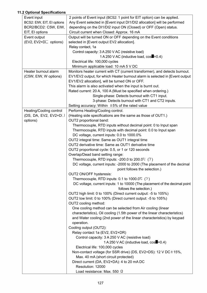
127
11.2 Optional Specifications
Event input
BCS2: EIW, EIT, EI options
BCR2/BCD2: C5W, EIW,
EIT, EI options
2 points of Event input (BCS2: 1 point for EIT option) can be applied.
Any Event selected in [Event input DI1/DI2 allocation] will be performed
depending on the DI1/DI2 input ON (Closed) or OFF (Open) status.
Circuit current when Closed: Approx. 16 mA
Event output
(EV2, EV2+D options)
Output will be turned ON or OFF depending on the Event conditions
selected in [Event output EV2 allocation].
Relay contact, 1a
Control capacity: 3 A 250 V AC (resistive load)
1 A 250 V AC (inductive load, cos =0.4)
Electrical life: 100,000 cycles
Minimum applicable load: 10 mA 5 V DC
Heater burnout alarm
(C5W, EIW, W options)
Monitors heater current with CT (current transformer), and detects burnout.
EV1/EV2 output, for which Heater burnout alarm is selected in [Event output
EV1/EV2 allocation], will be turned ON or OFF.
This alarm is also activated when the input is burnt out.
Rated current: 20 A, 100 A (Must be specified when ordering.)
Single-phase: Detects burnout with CT1 input.
3-phase: Detects burnout with CT1 and CT2 inputs.
Setting accuracy: Within 5% of the rated value
Heating/Cooling control
(DS, DA, EV2, EV2+D
options)
Performs Heating/Cooling control.
(Heating side specifications are the same as those of OUT1.)
OUT2 proportional band:
Thermocouple, RTD inputs without decimal point: 0 to Input span
Thermocouple, RTD inputs with decimal point: 0.0 to Input span
DC voltage, current inputs: 0.0 to 1000.0%
OUT2 integral time: Same as OUT1 integral time
OUT2 derivative time: Same as OUT1 derivative time
OUT2 proportional cycle: 0.5, or 1 or 120 seconds
Overlap/Dead band setting range:
Thermocouple, RTD inputs: -200.0 to 200.0 ( )
DC voltage, current inputs: -2000 to 2000 (The placement of the decimal
point follows the selection.)
OUT2 ON/OFF hysteresis:
Thermocouple, RTD inputs: 0.1 to 1000.0 ( )
DC voltage, current inputs: 1 to 10000 (The placement of the decimal point
follows the selection.)
OUT2 high limit: 0 to 100% (Direct current output: -5 to 105%)
OUT2 low limit: 0 to 100% (Direct current output: -5 to 105%)
OUT2 cooling method:
One cooling method can be selected from Air cooling (linear
characteristics), Oil cooling (1.5th power of the linear characteristics)
and Water cooling (2nd power of the linear characteristics) by keypad
operation.
Cooling output (OUT2):
Relay contact 1a (EV2, EV2+DR)
Control capacity: 3 A 250 V AC (resistive load)
1 A 250 V AC (inductive load, cos =0.4)
Electrical life: 100,000 cycles
Non-contact voltage (for SSR drive) (DS, EV2+DS): 12 V DC 15%,
Max. 40 mA (short circuit protected)
Direct current (DA, EV2+DA): 4 to 20 mA DC
Resolution: 12000
Load resistance: Max. 550

128
The following operations can be carried out from an external computer.
Serial communication and Console communication cannot be used
together.
(1) Reading and setting of the SV, PID values and various set values
(2) Reading of the PV and action status
(3) Function change
Cable length: Max 1.2 km, Cable resistance: Within 50 (Terminators are
not necessary, but if used, use 120 or more on both
sides.)
Communication line: EIA RS-485
Communication method: Half-duplex communication
Synchronization method: Start-stop synchronization
Communication speed: 9600, 19200, 38400 bps (Selectable by keypad)
Data bit/Parity:
Data bit: 7 bits, 8 bits,
Parity: Even/Odd/No parity (Selectable by keypad)
Stop bit: 1 bit, 2 bits (Selectable by keypad)
Communication protocol: Shinko protocol/Modbus ASCII/Modbus RTU
(Selectable by keypad)
Data format:
Communicationprotocol
Shinkoprotocol
Modbus ASCII Modbus RTU
Start bit 1 1 1
Data bit 7 7 (8)Selectable
8
Parity EvenEven (No parity, Odd)Selectable
No parity (Even, Odd)Selectable
Stop bit 1 1 (2)Selectable
1 (2)Selectable
Serial communication
(C5W, C5 options)
Number of connectable units: Maximum 31 units to 1 host computer
Communication error detection: Parity, checksum (Shinko protocol),
LRC (Modbus ASCII), CRC-16 (Modbus RTU)
Digital external setting:
Receives digital SV from Shinko programmable controllers (PC-900,
PCD-33A with SVTC option).
External setting input
(EIT option)
SV adds external analog signal to remote bias value.
Not available for Program control.
Setting signal: 4 to 20 mA DC
Allowable input: 50 mA DC max.
Input impedance: 50 max.
Input sampling period: 125 ms
Transmission output
(EIT option)
Converting the value (PV, SV, MV or DV transmission) to analog signal
every 125 ms, outputs the value in current or voltage.
Outputs Transmission output low limit value if Transmission output high
limit and low limit value are the same.
Resolution: 12000
Output: 4 to 20 mA DC (Load resistance: Maximum 550 )
Output accuracy: Within 0.3% of Transmission output span
Insulated power output
(P24 option)Output voltage: 24 3 V DC (when load current is 30 mA DC)
Ripple voltage: Within 200 mV DC (when load current is 30 mA DC)
Max. load current: 30 mA DC

129
12. TroubleshootingIf any malfunctions occur, refer to the following items after checking that power is being supplied to
the controller.
12.1 Indication
Problem Possible Cause Solution
The PV Display
indicates [ ].
Internal non-volatile IC
memory is defective.
Cancel the error code by pressing the key,
and perform data clearing. (p.108)
If the problem is not still solved, contact our
agency or us.
The PV Display
indicates [ ].
Data writing (in non-volatile
IC memory) error when
power failure occurs.
Cancel the error code by pressing the key,
and perform data clearing. (p.108)
The PV Display
indicates PV and
[ ] (*)
alternately.
Overscale.
PV has exceeded Input range
high limit value (scaling high
limit value for DC voltage,
current inputs).
Check the input signal source.
The PV Display
indicates PV and
[ ] (*)
alternately.
Underscale.
PV has dropped below Input
range low limit value (scaling
low limit value for DC voltage,
current inputs).
Check the input signal source and wiring of input
terminals.
PV has exceeded the
Indication range and Control
range.
Check the input signal source.
Burnout of thermocouple,
RTD or disconnection of DC
voltage (0 to 1 V DC)
Replace each sensor.How to check whether the sensor is burnt out[Thermocouple]If the input terminals of the instrument areshorted, and if a value around room temperatureis indicated, the instrument is likely to beoperating normally, however, the sensor may beburnt out.[RTD]If approx. 100 of resistance is connected tothe input terminals between A-B of the instrumentand between B-B is shorted, and if a valuearound 0 (32 ) is indicated, the instrument islikely to be operating normally, however, thesensor may be burnt out.[DC voltage (0 to 1 V DC)]
If the input terminals of the instrument are
shorted, and if a scaling low limit value is
indicated, the instrument is likely to be operating
normally, however, the signal wire may be
disconnected.
The PV Display
indicates [ ].
The PV Display
indicates [ ]
and [ ] (*)
alternately.
Check whether the input
terminals of thermocouple,
RTD or DC voltage (0 to 1 V
DC) are securely mounted to
the instrument input terminals.
Connect the sensor terminals to the instrumentinput terminals securely.
(*) Indicates when Enabled is selected in [Error indication Enabled/Disabled].

130
Problem Possible Cause Solution
PV has dropped below the
Indication range and Control
range.
Check the input signal source and wiring of input
terminals.
Check whether input signal
wire for DC voltage (1 to 5 V
DC) or direct current (4 to 20
mA DC) is disconnected.
How to check whether the input signal wire isdisconnected[DC voltage (1 to 5 V DC)]If the input to the input terminals of the instrumentis 1 V DC and if a scaling low limit value isindicated, the instrument is likely to be operatingnormally, however, the signal wire may bedisconnected.[Direct current (4 to 20 mA DC)]
If the input to the input terminals of the instrument
is 4 mA DC and if a scaling low limit value is
indicated, the instrument is likely to be operating
normally, however, the signal wire may be
disconnected.
Check whether input signal
wire for DC voltage (1 to 5 V
DC) or current (4 to 20 mA
DC) is securely connected to
the instrument input terminals.
Connect the input signal wire to the terminals ofthis instrument securely.
The PV Display
indicates [ ].
The PV Display
indicates [ ]
and [ ] (*)
alternately.
Check if polarity of thermo-
couple or compensating lead
wire is correct.
Check whether codes (A, B,
B) of RTD agree with the
instrument terminals.
Wire them correctly.
The PV Display
indicates [ ].
Hardware malfunction Contact our agency or us.
The PV Display
indicates [ ],
nothing or PV.
Control output OFF function
is enabled.
Press the key for approx. 1 second to cancelthe function.
Check whether sensor input
or temperature unit ( or )
is correct.
Select the sensor input and temperature unit (or ) correctly.
Sensor correction coefficient
or Sensor correction value is
unsuitable.
Set them to suitable values.
Check whether the sensor
specification is correct.
Use a sensor with appropriate specifications.
AC leaks into the sensor
circuit.
Use an ungrounded type sensor.
The indication of PV
Display is irregular
or unstable.
There may be equipment that
interferes with or makes noise
near the instrument.
Keep the instrument clear of any potentiallydisruptive equipment.
(*) Indicates when Enabled is selected in [Error indication Enabled/Disabled].

131
Problem Possible Cause Solution
Check whether the input
signal wire for DC voltage
(0 to 5 V DC, 0 to 10 V DC)
and direct current (0 to 20
mA DC) is disconnected.
Check the input signal wires of DC voltage (0 to 5V DC, 0 to 10 V DC) and direct current (0 to 20mA DC).How to check whether the input signal wire isdisconnected[DC voltage (0 to 5 V DC, 0 to 10 V DC)]
If the input to the input terminal of this controller is
1 V DC, and if a value (converted value from
scaling high, low limit setting) corresponding to
1 V DC is indicated, the controller is likely to be
operating normally, however, the input signal wire
may be disconnected.
[Direct current (0 to 20 mA DC)]
If the input to the input terminal of this controller is
4 mA DC, and if a value (converted value from
scaling high, low limit setting) corresponding to 4
mA DC is indicated, the controller is likely to be
operating normally, however, the input signal wire
may be disconnected.
The PV Display
keeps indicating
the value set in
[Scaling low limit].
Check whether the input
terminals for DC voltage
(0 to 5 V DC, 0 to 10 V DC) or
direct current (0 to 20 mA DC)
are securely connected to the
instrument input terminals.
Connect the input terminals of DC voltage and
current to the input terminals of this instrument
securely.
12.2 Key Operation
Problem Possible Cause Solution
Set value lock (Lock 1 or
Lock 4) is selected.
Release the lock in [Set value lock].None of the set
values can be set.
AT, ‘AT on startup’ or
Auto-reset is performing.
If AT or ‘AT on startup’ is performing, cancel AT or
‘AT on startup’.
Please wait until Auto-reset is finished.(It takes approximately 4 minutes until Auto-resetis finished.)
Only SV and Alarm
value can be set.
Other settings are
impossible.
Set value lock (Lock 2 or
Lock 5) is selected.
Release the lock in [Set value lock].
The setting
indication does not
change in the input
range, and new
values are unable to
be set.
Scaling high or low limit value
may be set at the point where
the value does not change.
Set it to a suitable value.

132
12.3 Control
Problem Possible Cause Solution
Sensor is out of order. Replace the sensor.
Check whether the sensor or
control output terminals are
securely mounted to the
instrument input terminals.
Ensure that the sensor or control output terminals
are mounted to the instrument input terminals
securely.
Temperature does
not rise.
Check whether the wiring of
sensor or control output
terminals is correct.
Wire them correctly.
The control output
remains in an ON
status.
OUT1 (or OUT2) low limit
value is set to 100% or higher.
Set it to a suitable value.
The control output
remains in an OFF
status.
OUT1 (or OUT2) high limit
value is set to 0% or less.
Set it to a suitable value.
AT or ‘AT on startup’ has not
been completed even if
approx. 4 hours have elapsed
since AT or ‘AT on startup’
started.
The PV display
indicates [ ].
For ‘AT on startup’, PV slope
and delay time cannot be
measured normally for P, I, D
calculation.
Set P, I, D and ARW values manually
For all other malfunctions, please contact our main office or dealers.

133
13. Character Table
13.1 Error Code
Error codes are indicated on the PV Display.
Error Code Error Contents Occurrence
Internal non-volatile IC memory is defective. When power
is turned ON.
Data writing (in non-volatile IC memory) error when power failure
occurs.
When power
is turned ON.
(*)PV has exceeded Input range high limit value (Scaling high limit
value for DC voltage, current inputs).
When
operating
(*)PV has dropped below Input range low limit value (Scaling low limit
value for DC voltage, current inputs).
When
operating
(*)Input burnout or disconnection.
Input value is outside of the Indication range and control range.
When
operating
Hardware malfunction When
operating
AT or ‘AT on startup’ has not been completed even if approx. 4 hours
have elapsed since AT or ‘AT on startup’ started.
For ‘AT on startup’, PV slope and delay time cannot be measured
normally for P, I, D calculation.
When AT or
‘AT on startup’
starts
(*) Indicates when Enabled is selected in [Error indication Enabled/Disabled].
13.2 Run Mode
Character Indicated Item Name
Control output OFF
Manual control
(MV flashes.)
13.3 Monitor Mode
The PV Display indicates PV, and the SV Display indicates setting item value.
Character Indicated Item Name
[MV]
MV
(Decimal point flashes.)
[Remaining time]
Remaining time (When Program control is performing)
[Step number]
Current step number (When Program control is performing) (BCS2)
to
[Memory number]
SV number (BCS2)
to

134
13.4 Initial Setting ModeThe PV Display (upper row) indicates setting characters, and the SV Display (lower row) indicatesfactory default value.
Characters,
Factory DefaultSetting Item, Setting Range
Input type
K -200 to 1370 K -328 to 2498
K -200.0 to 400.0 K -328.0 to 752.0
J -200 to 1000 J -328 to 1832
R 0 to 1760 R 32 to 3200
S 0 to 1760 S 32 to 3200
B 0 to 1820 B 32 to 3308
E -200 to 800 E -328 to 1472
T -200.0 to 400.0 T -328.0 to 752.0
N -200 to 1300 N -328 to 2372
PL- 0 to 1390 PL- 32 to 2534
C(W/Re5-26) 0 to 2315 C(W/Re5-26) 32 to 4199
Pt100 -200.0 to 850.0 Pt100 -328.0 to 1562.0
JPt100 -200.0 to 500.0 JPt100 -328.0 to 932.0
Pt100 -200 to 850 Pt100 -328 to 1562
JPt100 -200 to 500 JPt100 -328 to 932
4 to 20 mA DC -2000 to 10000
0 to 20 mA DC -2000 to 10000
0 to 1 V DC -2000 to 10000
0 to 5 V DC -2000 to 10000
1 to 5 V DC -2000 to 10000
0 to 10 V DC -2000 to 10000
Scaling high limit
Setting range: Scaling low limit value to input range high limit value
DC voltage, current inputs: -2000 to 10000 (*1)
Scaling low limit
Setting range: Input range low limit value to scaling high limit value
DC voltage, current inputs: -2000 to 10000 (*1)
Decimal point place
No decimal point
1 digit after decimal point
2 digits after decimal point
3 digits after decimal point(*1) The placement of the decimal point follows the selection.

135
Characters,
Factory DefaultSetting Item, Setting Range
Event output EV1 allocation
[Event Output Allocation Table]
No event
Alarm output, High limit alarm
Alarm output, Low limit alarm
Alarm output, High/Low limits alarm
Alarm output, High/Low limits independent alarm
Alarm output, High/Low limit range alarm
Alarm output, High/Low limit range independent alarm
Alarm output, Process high alarm
Alarm output, Process low alarm
Alarm output, High limit with standby alarm
Alarm output, Low limit with standby alarm
Alarm output, High/Low limits with standby alarm
Alarm output, High/Low limits with standby independentalarm
Heater burnout alarm output
Loop break alarm output
Time signal output
Output during AT
Pattern end output
Output by communication command
EV1 alarm value 0 Enabled/Disabled
Disabled
Enabled
EV1 alarm value
High limit alarm -(Input span) to Input span ( ) (*1) (*2)
Low limit alarm -(Input span) to Input span ( ) (*1) (*2)
High/Low limits alarm 0 to Input span ( ) (*1) (*2)
High/Low limits independent
alarm
0 to Input span ( ) (*1) (*2)
High/Low limit range alarm 0 to Input span ( ) (*1) (*2)
High/Low limit range
independent alarm
0 to Input span ( ) (*1) (*2)
Process high alarm Input range low limit to Input range high limit (*1) (*3)
Process low alarm Input range low limit to Input range high limit (*1) (*3)
High limit with standby alarm -(Input span) to Input span ( ) (*1) (*2)
Low limit with standby alarm -(Input span) to Input span ( ) (*1) (*2)
High/Low limits with standby
alarm
0 to Input span ( ) (*1) (*2)
High/Low limits with standby
independent alarm
0 to Input span ( ) (*1) (*2)
EV1 high limit alarm valueSetting range: Same as those of EV1 alarm value
(*1) The placement of the decimal point follows the selection.
(*2) For DC voltage, current inputs, the input span is the same as the scaling span.
(*3) For DC voltage, current inputs, input range low (or high) limit value is the same as scaling low (or high) limit value.

136
Characters,
Factory DefaultSetting Item, Setting Range
EV1 alarm hysteresis
Setting range: 0.1 to 1000.0 ( ),DC voltage, current inputs: 1 to 10000 (*1)
EV1 alarm delay timeSetting range: 0 to 10000 seconds
EV1 alarm Energized/De-energized
Energized
De-energized
TS1 output step number
Setting range: 1 to 9
TS1 OFF time
Setting range: 00:00 to 99:59 (*4)
TS1 ON time
Setting range: 00:00 to 99:59 (*4)
Event output EV2 allocation
[Event Output Allocation Table]
No event
Alarm output, High limit alarm
Alarm output, Low limit alarm
Alarm output, High/Low limits alarm
Alarm output, High/Low limits independent alarm
Alarm output, High/Low limit range alarm
Alarm output, High/Low limit range independent alarm
Alarm output, Process high alarm
Alarm output, Process low alarm
Alarm output, High limit with standby alarm
Alarm output, Low limit with standby alarm
Alarm output, High/Low limits with standby alarm
Alarm output, High/Low limits with standby independentalarm
Heater burnout alarm output
Loop break alarm output
Time signal output
Output during AT
Pattern end output
Output by communication command
Heating/Cooling control relay contact output
EV2 alarm value 0 Enabled/Disabled
Disabled
Enabled
(*1) The placement of the decimal point follows the selection.
(*4) Time unit follows the selection in [Step time unit].

137
Characters,
Factory DefaultSetting Item, Setting Range
EV2 alarm value
High limit alarm -(Input span) to Input span ( ) (*1) (*2)
Low limit alarm -(Input span) to Input span ( ) (*1) (*2)
High/Low limits alarm 0 to Input span ( ) (*1) (*2)
High/Low limits independent
alarm
0 to Input span ( ) (*1) (*2)
High/Low limit range alarm 0 to Input span ( ) (*1) (*2)
High/Low limit range
independent alarm
0 to Input span ( ) (*1) (*2)
Process high alarm Input range low limit to Input range high limit (*1) (*3)
Process low alarm Input range low limit to Input range high limit (*1) (*3)
High limit with standby alarm -(Input span) to Input span ( ) (*1) (*2)
Low limit with standby alarm -(Input span) to Input span ( ) (*1) (*2)
High/Low limits with standby
alarm
0 to Input span ( ) (*1) (*2)
High/Low limits with standby
independent alarm
0 to Input span ( ) (*1) (*2)
EV2 high limit alarm value
Setting range: Same as those of EV2 alarm value
EV2 alarm hysteresis
Setting range: 0.1 to 1000.0 ( ),
DC voltage, current inputs: 1 to 10000 (*1)
EV2 alarm delay time
Setting range: 0 to 10000 seconds
EV2 alarm Energized/De-energized
Energized
De-energized
TS2 output step number
Setting range: 1 to 9
TS2 OFF time
Setting range: 00:00 to 99:59 (*4)
TS2 ON time
Setting range: 00:00 to 99:59 (*4)
and CT1 current
value are alternately
indicated on the PVDisplay.
Heater burnout alarm 1 value
Setting range:
20 A: 0.0 to 20.0 A100 A: 0.0 to 100.0 A
and CT2 current
value are alternately
indicated on the PVDisplay.
Heater burnout alarm 2 value
Setting range:
20 A: 0.0 to 20.0 A100 A: 0.0 to 100.0 A
(*1) The placement of the decimal point follows the selection.
(*2) For DC voltage, current inputs, the input span is the same as the scaling span.
(*3) For DC voltage, current inputs, input range low (or high) limit value is the same as scaling low (or high) limit value.
(*4) Time unit follows the selection in [Step time unit].

138
Characters,
Factory DefaultSetting Item, Setting Range
Loop break alarm time
Setting range: 0 to 200 minutes
Loop break alarm span
Setting range: 0 to 150 ( ), or 0.0 to 150.0 ( )
DC voltage, current inputs: 0 to 1500 (*1)
Event input DI1 allocation
[Event Input Allocation Table]
Event input
function
Input ON
(Closed)
Input OFF
(Open)
No event
Set value memory
Control ON/OFF Control OFF Control ON
Direct/Reverse action Direct action Reverse action
Preset output 1
ON/OFF
Preset output Usual control
Preset output 2
ON/OFF
Preset output Usual control
Auto/Manual control Manual
control
Automatic
control
Remote/Local Remote Local
Program control
RUN/STOP
RUN STOP
Program control
Holding/Not holdingHolding Not holding
Program control
Advance function
Advance
function
Usual control
Integral action
Holding
Integral action
Holding
Usual
integral action
Event input DI2 allocation
Selection item: Same as those of Event input DI1 allocation
External setting input high limit
Setting range: External setting input low limit to Input range high limit (*1)
External setting input low limit
Setting range: Input range low limit to External setting input high limit (*1)
Transmission output type
PV transmission
SV transmission
MV transmission
DV transmission
(*1) The placement of the decimal point follows the selection.

139
Characters,
Factory DefaultSetting Item, Setting Range
Transmission output high limit
PV, SV transmission Transmission output low limit to Input range high limit
DC voltage, currents: -2000 to 10000
MV transmission Transmission output low limit to 105.0%
DV transmission Transmission output low limit to Scaling span (*1)
Transmission output low limit
PV, SV transmission Input range low limit to Transmission output high limit
DC voltage, currents: -2000 to 10000
MV transmission -5.0% to Transmission output high limit value
DV transmission -Scaling span to Transmission output high limit value (*1)
SV1
Setting range: Scaling low limit to Scaling high limit (*1)
SV2Setting range: Scaling low limit to Scaling high limit (*1)
SV3
Setting range: Scaling low limit to Scaling high limit (*1)
SV4
Setting range: Scaling low limit to Scaling high limit (*1)
(*1) The placement of the decimal point follows the selection.
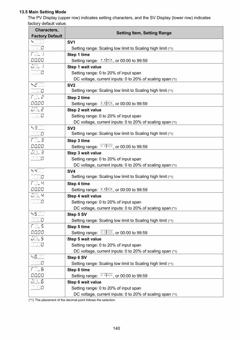
140
13.5 Main Setting Mode
The PV Display (upper row) indicates setting characters, and the SV Display (lower row) indicates
factory default value.
Characters,
Factory DefaultSetting Item, Setting Range
SV1
Setting range: Scaling low limit to Scaling high limit (*1)
Step 1 time
Setting range: , or 00:00 to 99:59
Step 1 wait value
Setting range: 0 to 20% of input span
DC voltage, current inputs: 0 to 20% of scaling span (*1)
SV2Setting range: Scaling low limit to Scaling high limit (*1)
Step 2 time
Setting range: , or 00:00 to 99:59
Step 2 wait value
Setting range: 0 to 20% of input span
DC voltage, current inputs: 0 to 20% of scaling span (*1)
SV3Setting range: Scaling low limit to Scaling high limit (*1)
Step 3 time
Setting range: , or 00:00 to 99:59
Step 3 wait value
Setting range: 0 to 20% of input span
DC voltage, current inputs: 0 to 20% of scaling span (*1)
SV4Setting range: Scaling low limit to Scaling high limit (*1)
Step 4 time
Setting range: , or 00:00 to 99:59
Step 4 wait value
Setting range: 0 to 20% of input span
DC voltage, current inputs: 0 to 20% of scaling span (*1)
Step 5 SV
Setting range: Scaling low limit to Scaling high limit (*1)
Step 5 time
Setting range: , or 00:00 to 99:59
Step 5 wait value
Setting range: 0 to 20% of input span
DC voltage, current inputs: 0 to 20% of scaling span (*1)
Step 6 SV
Setting range: Scaling low limit to Scaling high limit (*1)
Step 6 time
Setting range: , or 00:00 to 99:59
Step 6 wait value
Setting range: 0 to 20% of input span
DC voltage, current inputs: 0 to 20% of scaling span (*1)
(*1) The placement of the decimal point follows the selection.

141
Characters,
Factory DefaultSetting Item, Setting Range
Step 7 SV
Setting range: Scaling low limit to Scaling high limit (*1)
Step 7 time
Setting range: , or 00:00 to 99:59
Step 7 wait value
Setting range: 0 to 20% of input span
DC voltage, current inputs: 0 to 20% of scaling span (*1)
Step 8 SV
Setting range: Scaling low limit to Scaling high limit (*1)
Step 8 time
Setting range: , or 00:00 to 99:59
Step 8 wait value
Setting range: 0 to 20% of input span
DC voltage, current inputs: 0 to 20% of scaling span (*1)
Step 9 SV
Setting range: Scaling low limit to Scaling high limit (*1)
Step 9 time
Setting range: , or 00:00 to 99:59
Step 9 wait value
Setting range: 0 to 20% of input span
DC voltage, current inputs: 0 to 20% of scaling span (*1)
(*1) The placement of the decimal point follows the selection.

142
13.6 Sub Setting ModeThe PV Display (upper row) indicates setting characters, and the SV Display (lower row) indicatesfactory default value.
Characters,Factory Default Setting Item, Setting Range
AT/Auto-reset Perform/Cancel
AT/AT on startup/Auto-reset Cancel
AT Perform
AT on startup Perform
Auto-reset Perform
OUT1 proportional bandThermocouple, RTD input without decimal point: 0 to Input span ( )Thermocouple, RTD input with decimal point: 0.0 to Input span ( )DC voltage, current inputs: 0.0 to 1000.0%
Integral time
Setting range: 0 to 3600 seconds
Derivative time
Setting range: 0 to 1800 seconds
ARW
Setting range: 0 to 100%
Manual reset
Setting range: Proportional band value
OUT1 proportional cycle
Setting range: 0.5, or 1 to 120 secondsFactory default value:
• Relay contact output: 30 sec
• Non-contact voltage output: 3 sec
OUT1 ON/OFF hysteresis
Setting range: 0.1 to 1000.0 ( )DC voltage, current inputs: 1 to 10000 (*1)
OUT1 high limit
Setting range: OUT1 low limit value to 100%
(Direct current output type: OUT1 low limit value to 105%)
OUT1 low limit
Setting range: 0% to OUT1 high limit value
(Direct current output type: -5% to OUT1 high limit value)
OUT1 rate-of-change
Setting range: 0 to 100 %/second
OUT2 cooling method
Air cooling (linear characteristics)
Oil cooling (1.5th power of the linear characteristics)
Water cooling (2nd power of the linear characteristics)
OUT2 proportional bandThermocouple, RTD input without decimal point: 0 to Input span ( )Thermocouple, RTD input with decimal point: 0.0 to Input span ( )DC voltage, current inputs: 0.0 to 1000.0%
OUT2 proportional cycle
Setting range: 0.5, or 1 to 120 secondsFactory default value:
• EV2(*2), EV2+DR: 30 sec
• DS, EV2+DS: 3 sec
OUT2 ON/OFF hysteresis
Setting range: 0.1 to 1000.0 ( ),DC voltage, current inputs: 1 to 10000 (*1)
(*1) The placement of the decimal point follows the selection.(*2) When EV2 is selected { (Heating/Cooling control relay contact output) is selected in [Event output EV2 allocation]}.

143
Characters,Factory Default Setting Item, Setting Range
OUT2 high limit
Setting range: OUT2 low limit value to 100%(Direct current output type: OUT2 low limit value to 105%)
OUT2 low limit
Setting range: 0% to OUT2 high limit value(Direct current output type: -5% to OUT2 high limit value)
Overlap/Dead band
Setting range: -200.0 to 200.0 ( ),DC voltage, current inputs: -2000 to 2000 (*1)
Direct/Reverse action
Reverse (Heating) action
Direct (Cooling) action
EV1 alarm value
High limit alarm -(Input span) to Input span ( ) (*1) (*2)
Low limit alarm -(Input span) to Input span ( ) (*1) (*2)
High/Low limits alarm 0 to Input span ( ) (*1) (*2)
High/Low limits independent 0 to Input span ( ) (*1) (*2)
High/Low limit range alarm 0 to Input span ( ) (*1) (*2)
High/Low limit rangeindependent alarm
0 to Input span ( ) (*1) (*2)
Process high alarm Input range low limit to Input range high limit (*1) (*3)
Process low alarm Input range low limit to Input range high limit (*1) (*3)
High limit with standby alarm -(Input span) to Input span ( ) (*1) (*2)
Low limit with standby alarm -(Input span) to Input span ( ) (*1) (*2)
High/Low limits with standby 0 to Input span ( ) (*1) (*2)
High/Low limits with standbyindependent alarm
0 to Input span ( ) (*1) (*2)
EV1 high limit alarm value
Setting range: Same as those of EV1 alarm value
EV2 alarm value
Setting range: Same as those of EV1 alarm value
EV2 high limit alarm value
Setting range: Same as those of EV1 alarm value
and CT1 currentvalue are alternatelyindicated on the PVDisplay.
Heater burnout alarm 1 value
Setting range:
20.0 A: 0.0 to 20.0 A100.0 A: 0.0 to 100.0 A
and CT2 currentvalue are alternatelyindicated on the PVDisplay.
Heater burnout alarm 2 value
Setting range:
20.0 A: 0.0 to 20.0 A100.0 A: 0.0 to 100.0 A
Loop break alarm time
Setting range: 0 to 200 minutes
Loop break alarm spanThermocouple, RTD input without decimal point: 0 to 150 ( )Thermocouple, RTD input with decimal point: 0.0 to 150.0 ( )DC voltage, current inputs: 0 to 1500 (*1)
(*1) The placement of the decimal point follows the selection.(*2) For DC voltage, current inputs, the input span is the same as the scaling span.(*3) For DC voltage, current inputs, input range low (or high) limit value is the same as scaling low (or high) limit value.

144
13.7 Engineering Mode 1
The PV Display (upper row) indicates setting characters, and the SV Display (lower row) indicates
factory default value.
Characters,
Factory DefaultSetting Item, Setting Range
Set value lock
Change via KeypadChange via Software
Communication
Unlock All set values can be changed. All set values can be
Lock 1 None of the set values can be
changed.
changed.
Lock 2 In Fixed value control, only SV
and Alarm value can be changed.
In Program control, Step SV,
Step time and Alarm value can
be changed.
Lock 3 All set values can be changed.
Lock 4 None of the set values can be
changed.
Lock 5 In Fixed value control, only SV
and Alarm value can be changed.
In Program control, Step SV,
Step time and Alarm value can
be changed.
Setting items – except Input
type, Controller/Converter –
can be changed temporarily
via software communication.
However, if power is turned
ON again, the set values
revert to the values before
Lock 3, 4 or 5 was selected.
Event input DI1 allocation
[Event Input Allocation Table]
Event input
function
Input ON
(Closed)
Input OFF
(Open)
No event
Set value memory
Control ON/OFF Control OFF Control ON
Direct/Reverse
action
Direct
action
Reverse
action
Preset output 1
ON/OFF
Preset output Usual control
Preset output 2
ON/OFF
Preset output Usual control
Auto/Manual
control
Manual
control
Automatic
control
Remote/Local Remote Local
Program control
RUN/STOP
RUN STOP
Program control
Holding/Not
holding
Holding Not holding
Program control
Advance function
Advance
function
Usual control
Integral action
holding
Integral action
holding
Usual
integral action

145
Characters,Factory Default Setting Item, Setting Range
Event input DI2 allocation
Selection item: Same as Event input DI1 allocation
Event output EV1 allocation
[Event Output Allocation Table]
No event
Alarm output, High limit alarm
Alarm output, Low limit alarm
Alarm output, High/Low limits alarm
Alarm output, High/Low limits independent alarm
Alarm output, High/Low limit range alarm
Alarm output, High/Low limit range independent alarm
Alarm output, Process high alarm
Alarm output, Process low alarm
Alarm output, High limit with standby alarm
Alarm output, Low limit with standby alarm
Alarm output, High/Low limits with standby alarm
Alarm output, High/Low limits with standby independentalarm
Heater burnout alarm output
Loop break alarm output
Time signal output
Output during AT
Pattern end output
Output by communication command
EV1 alarm value 0 Enabled/Disabled
Disabled
Enabled
EV1 alarm value
High limit alarm -(Input span) to Input span ( ) (*1) (*2)
Low limit alarm -(Input span) to Input span ( ) (*1) (*2)
High/Low limits alarm 0 to Input span ( ) (*1) (*2)
High/Low limits independentalarm
0 to Input span ( ) (*1) (*2)
High/Low limit range alarm 0 to Input span ( ) (*1) (*2)
High/Low limit range
independent alarm
0 to Input span ( ) (*1) (*2)
Process high alarm Input range low limit to Input range high limit (*1) (*3)
Process low alarm Input range low limit to Input range high limit (*1) (*3)
High limit with standby alarm -(Input span) to Input span ( ) (*1) (*2)
Low limit with standby alarm -(Input span) to Input span ( ) (*1) (*2)
High/Low limits with standby
alarm
0 to Input span ( ) (*1) (*2)
High/Low limits with standby
independent alarm
0 to Input span ( ) (*1) (*2)
EV1 high limit alarm value
Setting range: Same as those of EV1 alarm value
(*1) The placement of the decimal point follows the selection.(*2) For DC voltage, current inputs, the input span is the same as the scaling span.(*3) For DC voltage, current inputs, input range low (or high) limit value is the same as scaling low (or high) limit value.
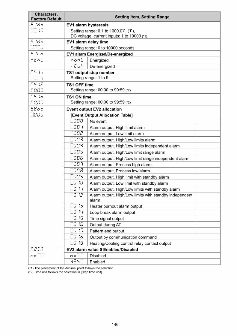
146
Characters,Factory Default Setting Item, Setting Range
EV1 alarm hysteresis
Setting range: 0.1 to 1000.0 ( ),DC voltage, current inputs: 1 to 10000 (*1)
EV1 alarm delay time
Setting range: 0 to 10000 seconds
EV1 alarm Energized/De-energized
Energized
De-energized
TS1 output step numberSetting range: 1 to 9
TS1 OFF timeSetting range: 00:00 to 99:59 (*2)
TS1 ON timeSetting range: 00:00 to 99:59 (*2)
Event output EV2 allocation
[Event Output Allocation Table]
No event
Alarm output, High limit alarm
Alarm output, Low limit alarm
Alarm output, High/Low limits alarm
Alarm output, High/Low limits independent alarm
Alarm output, High/Low limit range alarm
Alarm output, High/Low limit range independent alarm
Alarm output, Process high alarm
Alarm output, Process low alarm
Alarm output, High limit with standby alarm
Alarm output, Low limit with standby alarm
Alarm output, High/Low limits with standby alarm
Alarm output, High/Low limits with standby independentalarm
Heater burnout alarm output
Loop break alarm output
Time signal output
Output during AT
Pattern end output
Output by communication command
Heating/Cooling control relay contact output
EV2 alarm value 0 Enabled/Disabled
Disabled
Enabled
(*1) The placement of the decimal point follows the selection.(*2) Time unit follows the selection in [Step time unit].

147
Characters,Factory Default Setting Item, Setting Range
EV2 alarm value
High limit alarm -(Input span) to Input span ( ) (*1) (*2)
Low limit alarm -(Input span) to Input span ( ) (*1) (*2)
High/Low limits alarm 0 to Input span ( ) (*1) (*2)
High/Low limits independentalarm
0 to Input span ( ) (*1) (*2)
High/Low limit range alarm 0 to Input span ( ) (*1) (*2)
High/Low limit rangeindependent alarm
0 to Input span ( ) (*1) (*2)
Process high alarm Input range low limit to Input range high limit (*1) (*3)
Process low alarm Input range low limit to Input range high limit (*1) (*3)
High limit with standby alarm -(Input span) to Input span ( ) (*1) (*2)
Low limit with standby alarm -(Input span) to Input span ( ) (*1) (*2)
High/Low limits with standbyalarm
0 to Input span ( ) (*1) (*2)
High/Low limits with standbyindependent alarm
0 to Input span ( ) (*1) (*2)
EV2 high limit alarm value
Setting range: Same as those of EV2 alarm value
EV2 alarm hysteresis
Setting range: 0.1 to 1000.0 ( ),DC voltage, current inputs: 1 to 10000 (*1)
EV2 alarm delay time
Setting range: 0 to 10000 seconds
EV2 alarm Energized/De-energized
Energized
De-energized
TS2 output step number
Setting range: 1 to 9
TS2 OFF time
Setting range: 00:00 to 99:59 (*4)
TS2 ON time
Setting range: 00:00 to 99:59 (*4)
Sensor correction coefficient
Setting range: -10.000 to 10.000
Sensor correction
Setting range: -1000.0 to 1000.0 ( )
DC voltage, current inputs: -10000 to 10000 (*1)
PV filter time constant
Setting range: 0.0 to 10.0 seconds
Communication protocol
Shinko protocol
Modbus ASCII
Modbus RTU
Shinko protocol (JC command allocated)
Modbus ASCII (JC command allocated)
Modbus RTU (JC command allocated)
(*1) The placement of the decimal point follows the selection.
(*2) For DC voltage, current inputs, the input span is the same as the scaling span.
(*3) For DC voltage, current inputs, input range low (or high) limit value is the same as scaling low (or high) limit value.
(*4) Time unit follows the selection in [Step time unit].

148
Characters,
Factory DefaultSetting Item, Setting Range
Instrument number
0 to 95
Communication speed
9600 bps
19200 bps
38400 bps
Data bit/Parity
8 bits/No parity
7 bits/No parity
8 bits/Even
7 bits/Even
8 bits/Odd
7 bits/Odd
Stop bit
1 bit
2 bits
Response delay time
Setting range: 0 to 1000 ms
SVTC bias
Setting range: 20% of the input spanDC voltage, current inputs: 20% of scaling span (*1)
Remote/Local
Local
Remote
External setting input high limit
Setting range: External setting input low limit to Input range high limit
External setting input low limit
Setting range: Input range low limit to External setting input high limit
Remote bias
Setting range: 20% of input span
DC voltage, current inputs: 20% of scaling span (*1)
Transmission output type
PV transmission
SV transmission
MV transmission
DV transmission
Transmission output high limit
PV, SV transmission Transmission output low limit to Input range high limit value
MV transmission Transmission output low limit to 105.0%
DV transmission Transmission output low limit to Scaling span (*1)
Transmission output low limit
PV, SV transmission Input range low limit to Transmission output high limit value
MV transmission -5.0% to Transmission output high limit value
DV transmission -Scaling span to Transmission output high limit value (*1)
(*1) The placement of the decimal point follows the selection.

149
Characters,
Factory DefaultSetting Item, Setting Range
Step time unit
Hours:Minutes
Minutes:Seconds
Power restore action
Stops after power is restored
Continues (resumes) after power is restored.
Suspends (on hold) after power is restored.
Program start temperature
Setting range: Scaling low limit value to Scaling high limit value (*1)
Program control start type
PV start
PVR start
SV start
Number of repetitions
Setting range: 0 to 10000 times
SV Rise/Fall rate start type
SV start
PV start
SV rise rate
Setting range: 0 to10000 /min ( /min)
Thermocouple, RTD inputs with a decimal point: 0.0 to 1000.0 /min ( /min)
DC voltage, current inputs: 0 to 10000/min
SV fall rate
Setting range: 0 to10000 /min ( /min)
Thermocouple, RTD inputs with a decimal point: 0.0 to 1000.0 /min ( /min)
DC voltage, current inputs: 0 to 10000/min
Indication when control output OFF
OFF indication
No indication
PV indication
PV indication + Any Alarm active
AT biasSetting range: 0 to 50 (0 to 100 ), or 0.0 to 50.0 (0.0 to 100.0 )
AT gain
Setting range: 0.1 to 10.0 times
Output status when input errors occur
Output OFF
Output ON
OUT/OFF key function
Control output OFF function
Auto/Manual control
Program control
Auto/Manual after power ON
Automatic control
Manual control
(*1) The placement of the decimal point follows the selection.

150
Characters,
Factory DefaultSetting Item, Setting Range
Indication time
Setting range: 00:00 to 60:00 (Minutes:Seconds)
When set to 00:00, Displays remain ON.
OUT1 MV preset value
Setting range: OUT1 low limit to OUT1 high limit
For Direct current output type, and when OUT1 is in ON/OFF control: OUT1 low
limit or OUT1 high limit
For Relay contact output or Non-contact voltage output type, and when OUT1 is
in ON/OFF control: 0.0% or 100.0%
OUT2 MV preset valueSetting range: OUT2 low limit to OUT2 high limitFor DA, EV2+DA options, and when OUT2 is in ON/OFF control: OUT2 low limitor OUT2 high limit
For DR, DS, EV2+DR, EV2+DS options, and when OUT2 is in ON/OFF control:
0.0% or 100.0%
Controller/Converter function
Controller
Converter
Error indication Enabled/Disabled
Disabled
Enabled
13.8 Engineering Mode 2
The PV Display (upper row) indicates setting characters, and the SV Display (lower row) indicates
factory default value.
Characters,
Factory DefaultSetting Item, Setting Range
Control method
PID control
2DOF PID control
Proportional gain 2DOF coefficient (α)
0.00 to 1.00
Integral 2DOF coefficient (β)
0.00 to 10.00

14. Key Operation Flowchart
Initial Setting Mode
Input type Event input
DI2 allocation
Scaling high limit External setting
input high limit
Scaling low limit External setting
input low limit
Decimal point Transmission
place output type
Event output Transmission
EV1 allocation output high limit
Event output Transmission
EV2 allocation output low limit
Heater burnout SV1 (*2)
alarm 1 value
Heater burnout SV2 (*2)
alarm 2 value
Loop break alarm SV3 (*2)
time
Loop break alarm SV4 (*2)
span
Event input
DI1 allocation Reverts to RUN mode.
Main Setting Mode
SV1
Step 1 time
Step 1 wait value
SV2
Indicates settingitemsfor Steps 2 to 9. (*3)
Step 9 wait value
Reverts to RUN mode.
Monitor Mode
MV indication
[MV] (Decimal point flashes.)
Remaining time
[Remaining time] (*5)
Current step
[Step number] number (BCS2) (*5)
SV number
[Memory number] (BCS2) (*2)
Reverts to RUN mode.
Power ONIf Data clear (No) is selected, and is pressed, the unitwill revert to PV/SV Display. If Data clear (Yes) isselected, the unit automatically reverts to PV/SV Display after datais cleared.
+ + + (3 sec) Data clearStarts from previousstatus(last shutdown).
Yes/No
RUN Mode By pressing the key for approx. 1 sec, one of the following items selected in [OUT/OFF key function] is indicated.
Program Control Control Output OFF Function Auto/Manual Control
PV/SV Display (1 sec) Program control Control output OFF Manual control
(*1) RUN (MV flashes.)
If Alarm output (001 to 012) or Time signal output (015) is selected in [Event output
EV1/EV2 allocation], and the key is pressed, the following items will be indicated.
If ‘Alarm output’ is selected in[Event output EV1 allocation]
If ‘Time signal output’ is selected in[Event output EV1 allocation]
EV1 alarm value 0 TS1 output
Enabled/Disabled step number
EV1 alarm value TS1 OFF time
EV1 high limit TS1 ON time
alarm value
By pressing the key, theunit moves to the item after[Event output EV1 allocation].
If Alarm output (001 to 012) orTime signal output (015) isselected in [Event output EV2allocation], read EV2, TS2 forEV1, TS1.
EV1 alarm
hysteresis
EV1 alarm
delay time
EV1 alarm Ener-
gized/De-energized
Sub Setting Mode
AT/Auto-reset OUT2 ON/OFF
Perform/Cancel hysteresis
OUT1 proportional OUT2 high limit
band
Integral time OUT2 low limit
Derivative time Overlap/Dead
band
ARW Direct/Reverse
action
Manual reset EV1 alarm value
OUT1 proportional EV1 high limit
cycle alarm value
OUT1 ON/OFF EV2 alarm value
hysteresis
OUT1 high limit EV2 high limit
alarm value
OUT1 low limit Heater burnout
alarm 1 value
OUT1 Heater burnout
rate-of-change alarm 2 value
OUT2 cooling Loop break alarm
method time
OUT2 proportional Loop break alarm
band span
OUT2 proportional
cycle Reverts to RUN mode.
Engineering Mode 1
Set value lock SVTC bias SV rise rate
Event input Remote/Local SV fall rate
DI1 allocation
Event input External setting Indication when
DI2 allocation input high limit control output OFF
Event output External setting AT bias
EV1 allocation input low limit
Event output Remote bias AT gain
EV2 allocation
Sensor correction Transmission Output status when
coefficient output type input errors occur
Sensor correction Transmission OUT/OFF key
output high limit function
PV filter time Transmission Auto/Manual after
constant output low limit power interruption
Communication Step time unit Indication time
protocol
Instrument Power restore OUT1 MV preset
number action value
Communication Program start OUT2 MV preset
speed temperature value
Data bit/Parity Program control Controller/
start type Converter
Stop bit Number of Error indication
repetitions Enabled/Disabled
Response delay SV Rise/Fall rate
time start type Reverts to RUN mode.
Engineering Mode 2
Control method
Proportional gain
2DOF coefficient (α)
Integral 2DOF
coefficient (β)
Reverts to RUN mode.
● About Setting Item
Input type • Upper left: PV Display: Indicates setting characters.• Lower left: SV Display: Indicates factory default.• Right side: Indicates the setting item.
: This setting item is optional, and appears only when the option is ordered.
(*1) If ‘Program control’ is selected in [OUT/OFF key function], the unit entersStandby mode (Program control waiting).
(*2) Not available if ‘Program control’ is selected in [OUT/OFF key function].
(*3) If the option is ordered, and if ‘Set value memory’ is selected in [Event input DI1/DI2allocation], setting items SV2 to SV4 are available.If ‘Program control’ is selected in [OUT/OFF key function], SV2 to SV9, Steps 1
to 9 time, Steps 1 to 9 wait value are available.(*4) The unit cannot proceed to Monitor mode if it is in Standby of Program control.(*5) Available only when ‘Program control’ is selected in [OUT/OFF key function].
● Key Operation• + + + (3 sec): Press and hold , , , (in that order) for approx. 3 sec.• + (3 sec): Press and hold the , keys (in that order) together for approx. 3 sec.• + : Press and hold the , keys (in that order) together.• + (3 sec): Press and hold the , keys (in that order) together for approx. 3 sec.• + + (5 sec): Press and hold the , and keys (in that order) together for approx. 5 sec.• Set (or select) each item with the or key, and register the value with the key• : If the key is pressed, the unit proceeds to the next item, illustrated by an arrow.
Pressing key moves back to the previous item.• To revert to RUN mode, press and hold the key for approx. 3 sec while in any mode.• To revert to RUN mode, press and hold the key for approx. 3 sec while in any mode.
If ‘Control output OFF function’ is selected in [OUT/OFF key function], the unit will enter Controloutput OFF status. If ‘Auto/Manual control’ is selected, the unit will enter Manual control status.If ‘Program control’ is selected, the unit will enter Program control RUN or Standby mode.
+ (3 sec) + + (3 sec) + + (5 sec)
(3 sec) (*4)
Input type
K -200 to 1370
K -200.0 to 400.0
J -200 to 1000
R 0 to 1760
S 0 to 1760
B 0 to 1820
E -200 to 800
T -200.0 to 400.0
N -200 to 1300
PL- 0 to 1390
C(W/Re5-26) 0 to 2315
Pt100 -200.0 to 850.0
JPt100 -200.0 to 500.0
Pt100 -200 to 850
JPt100 -200 to 500
K -328 to 2498
K -328.0 to 752.0
J -328 to 1832
R 32 to 3200
S 32 to 3200
B 32 to 3308
E -328 to 1472
T -328.0 to 752.0
N -328 to 2372
PL- 32 to 2534
C(W/Re5-26) 32 to 4199
Pt100 -328.0 to 1562.0
JPt100 -328.0 to 932.0
Pt100 -328 to 1562
JPt100 -328 to 932
4 to 20 mA -2000 to 10000
0 to 20 mA -2000 to 10000
0 to 1 V -2000 to 10000
0 to 5 V -2000 to 10000
1 to 5 V -2000 to 10000
0 to 10 V -2000 to 10000
Decimal point place
No decimal point
1 digit after decimal point
2 digits after decimal point
3 digits after decimal point
Event output EV1/EV2 allocation
No event
High limit alarm
Low limit alarm
H/L limits alarm
H/L limits independent
H/L limit range alarm
H/L limit rangeindependent
Process high alarm
Process low alarm
High limit with standby
Low limit with standby
H/L limits with standby
H/L limits with standbyindependent
Heater burnout alarmoutput
Loop break alarm output
Time signal output
Output during AT
Pattern end output
Output by communicationcommandHeating/Cooling control relaycontact output (for EV2 only)
EV1/EV2 alarm value 0Disabled/Enabled
Disabled
Enabled
EV1/EV2 alarmEnergized/De-energized
Energized
De-energized
Event input DI1/DI2 allocation
No event
Set value memory
Control ON/OFF
Direct/Reverse action
Preset output 1 ON/OFF
Preset output 2 ON/OFF
Auto/Manual control
Remote/Local
Program controlRun/Stop
Program controlHolding/Not holding
Program controlAdvance function
Integral action Holding
Transmission output
PV transmission
SV transmission
MV transmission
DV transmission
AT/Auto-reset Perform/Cancel
AT/Auto-reset Cancel
AT Perform
AT on startup Perform
Auto-reset Perform
OUT2 cooling method
Air cooling
Oil cooling
Water cooling
Direct/Reverse action
Reverse action
Direct action
Set value lock
Unlock
Lock 1
Lock 2
Lock 3
Lock 4
Lock 5
Communication protocol
Shinko protocol
Modbus ASCII
Modbus RTU
Shinko protocol(JC command allocation)
Modbus ASCII(JC command allocation)
Modbus RTU(JC command allocation)
Communication speed
9600 bps
19200 bps
38400 bps
Data bit/Parity
8 bits/No parity
7 bits/No parity
8 bits/Even
7 bits/Even
8 bits/Odd
7 bits/Odd
Stop bit
1 bit
2 bits
Remote/Local
Local
Remote
Step time unit
Hours:Minutes
Minutes:Seconds
Power restore action
Stop
Continue (resume)
Suspend (on hold)
Program control start type
PV start
PVR start
SV start
SV Rise/Fall rate start type
SV start
PV start
Indication when control output OFF
OFF indication
No indication
PV indication
PV + Any Alarm active
Output status when input errors occur
Output OFF
Output ON
OUT/OFF key function
Control output OFF
Auto/Manual control
Program control
Auto/Manual after power interruption
Automatic control
Manual control
Controller/Converter function
Controller
Converter
Error indication Enabled/Disabled
Disabled
Enabled
Control method
Usual PID
2DOF PID

***** Inquiries *****
For any inquiries about this unit, please contact our agency or the
vendor where you purchased the unit after checking the following.
[Example]
• Model ------------------------------ BCS2R00-12
• Option ----------------------------- EV2, C5W (100A)
• Serial number ------------------- No. 145F05000
In addition to the above, please let us know the details of the
malfunction, or discrepancy, and the operating conditions.
No.BCx22E5 2016.08
SHINKO TECHNOS CO., LTD.OVERSEAS DIVISION
:Head Office
URL:
E-mail:
2-5-1, Senbahigashi, Minoo, Osaka, Japan
http://www.shinko-technos.co.jp
Tel :
Fax:
+81-72-727-6100
+81-72-727-7006