Embed Size (px)
Citation preview

1
INSTRUCTION MANUAL
FOR
MICROCOMPUTER BASED
TEMPERATURE INDICATING CONTROLLER
FCS-23A
Thank you for your purchase of our Microcomputer based Temperature Indicating Controller FCS-23A. This manual contains instructions for the mounting, functions, operations and notes when operating the FCS-23A. For model confirmation and unit specifications, please read this instruction manual carefully before starting operation.
To prevent accidents arising from the use of this controller, please ensure the operator using it receives this manual.
2
NOTES TO USERS FCS-23A
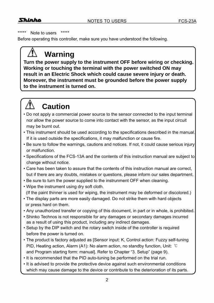
***** Note to users ***** Before operating this controller, make sure you have understood the following.
Warning Turn the power supply to the instrument OFF before wiring or checking. Working or touching the terminal with the power switched ON may
result in an Electric Shock which could cause severe injury or death. Moreover, the instrument must be grounded before the power supply to the instrument is turned on.
Caution • Do not apply a commercial power source to the sensor connected to the input terminal
nor allow the power source to come into contact with the sensor, as the input circuit may be burnt out.
• This instrument should be used according to the specifications described in the manual. If it is used outside the specifications, it may malfunction or cause fire.
• Be sure to follow the warnings, cautions and notices. If not, it could cause serious injury or malfunction.
• Specifications of the FCS-13A and the contents of this instruction manual are subject to change without notice.
• Care has been taken to assure that the contents of this instruction manual are correct, but if there are any doubts, mistakes or questions, please inform our sales department.
• Be sure to turn the power supplied to the instrunment OFF when cleaning. • Wipe the instrument using dry soft cloth.
(If the paint thinner is used for wiping, the instrument may be deformed or discolored.) • The display parts are more easily damaged. Do not strike them with hard objects or press hard on them. • Any unauthorized transfer or copying of this document, in part or in whole, is prohibited. • Shinko Technos is not responsible for any damages or secondary damages incurred
as a result of using this product, including any indirect damages. • Setup by the DIP switch and the rotary switch inside of the controller is required
before the power is turned on. • The product is factory adjusted as [Sensor input: K, Control action: Fuzzy self-tuning
PID, Heating action, Alarm (A1): No alarm action, no standby function, Unit: and Program starting form: manual]. Refer to Chapter “3. Setup” (page 9).
• It is recommended that the PID auto-tuning be performed on the trial run. • It is advised to provide the protective device against such environmental conditions
which may cause damage to the device or contribute to the deterioration of its parts.

3
CONTENTS FCS-23A
--- CONTENTS --- 1. Model names
1.1 Model names ---------------------------------------------------------------------------- 5 1.2 How to indicate the model nameplate ----------------------------------------------- 6
2. Name and functions of the sections -------------------------------------------- 7 3. Setup
3.1 Taking the internal assembly out ------------------------------------------------------ 9 3.2 Switch setting (multi-function) --------------------------------------------------------- 9 3.3 Insertion of the internal assembly ---------------------------------------------------- 12
4. Operations 4.1 Operating flow chart -------------------------------------------------------------------- 13 4.2 Operations
(1) PV/SV display mode ------------------------------------------------------------------ 15 (2) Main setting mode --------------------------------------------------------------------- 16 (3) Sub setting mode
Setting value memory number selection ----------------------------------------- 16 Auto-tuning Perform/Cancel --------------------------------------------------------- 16 Proportional band setting ------------------------------------------------------------- 17
Integral time setting -------------------------------------------------------------------- 17 Derivative time setting ----------------------------------------------------------------- 17
Proportional cycle setting ------------------------------------------------------------- 17 Manual reset setting ------------------------------------------------------------------- 18 Alarm 1, 2 (A1, A2) settings ---------------------------------------------------------- 18 Loop break alarm time setting ------------------------------------------------------- 19 Loop break alarm span setting ------------------------------------------------------ 19
(4) Auxiliary function setting mode 1 Setting value lock designation ------------------------------------------------------ 20 Main setting value high limit setting ------------------------------------------------ 21 Main setting value low limit setting ------------------------------------------------- 21 Sensor correction setting ------------------------------------------------------------- 21
Instrument number setting ----------------------------------------------------------- 21 Transfer rate selection ---------------------------------------------------------------- 22 Communication protocol selection ------------------------------------------------- 22
(5) Auxiliary function setting mode 2 Scaling high limit value setting ------------------------------------------------------ 23 Scaling low limit value setting ------------------------------------------------------- 23 PV filter time constant setting ------------------------------------------------------- 23 Main output high limit setting -------------------------------------------------------- 24
Main output low limit setting --------------------------------------------------------- 24

4
CONTENTS FCS-23A Main output ON/OFF action hysteresis setting --------------------------------- 24 Alarm 1, 2 (A1, A2) action Energized/Deenergized selections ------------- 24 Alarm 1, 2 (A1, A2) hysteresis settings ------------------------------------------- 25 Alarm 1, 2 (A1, A2) action delayed timer settings ------------------------------ 25 Display selection when control output is off ------------------------------------- 26 Main setting value rising rate setting ---------------------------------------------- 26 Main setting value falling rate setting --------------------------------------------- 27
(6) Program mode Program control change -------------------------------------------------------------- 29 Step 1 to 7 time setting --------------------------------------------------------------- 29
(7) Control output OFF function -------------------------------------------------------- 31 (8) Output manipulating value and Step rest time indication mode ----------- 32
5. Setting value memory number external selection ----------------------- 33 6. Running
6.1 When using the FCS-23A as a Temperature controller ------------------------- 34 6.2 When using the FCS-23A as a Simplified program controller ----------------- 35
7. Action explanations 7.1 Standard action drawings --------------------------------------------------------------- 36 7.2 ON/OFF action drawings ---------------------------------------------------------------- 37 7.3 Pattern end action drawing ------------------------------------------------------------- 37 7.4 Alarm 1, 2 (A1, A2) action drawings ------------------------------------------------- 38
8. Control actions 8.1 Fuzzy self-tuning -------------------------------------------------------------------------- 40 8.2 Explanations of PID ---------------------------------------------------------------------- 41 8.3 PID auto-tuning of this controller ----------------------------------------------------- 42
9. Other functions ---------------------------------------------------------------------------- 43 10. Mounting to control panel
10.1 Site selection ------------------------------------------------------------------------------- 44 10.2 External dimension drawing ------------------------------------------------------------ 44 10.3 Panel cutout drawing --------------------------------------------------------------------- 44 10.4 Mounting ------------------------------------------------------------------------------------- 45
11. Wiring connection 11.1 Terminal arrangement -------------------------------------------------------------------- 46 11.2 Wiring connection examples ------------------------------------------------------------ 48
12. Specifications 12.1 Standard specifications ------------------------------------------------------------------ 49 12.2 Optional specifications ------------------------------------------------------------------- 52
13. Troubleshooting --------------------------------------------------------------------------- 55 14. Character table ----------------------------------------------------------------------------- 58

5
MODEL NAME FCS-23A 1. Model names 1.1 Model names Standard models
F C S – 2 3 A – / M Series name: FCS-230 Control action 3 PID control (*1) Alarm A Alarm action (*2)
R Relay contact output S Non-contact voltage output Output A Current output
Input M Multi-range input (*3) *1: Fuzzy self-tuning PID, PID, PD and ON/OFF action are selectable by internal DIP
switch. *2: 12 types of alarm action and no alarm action are selectable by internal rotary switch
and DIP switch. *3: 12 types of input, Thermocouple, RTD are selectable by internal rotary switch
and DIP switch. Alphanumeric character to represent the functions or type is applied to the . [Example] FCS-23A- R / M, A2 , LA
Loop break alarm output Alarm 2 (A2) output Relay contact output Optional code
Code Specification A2 Alarm 2 output (including the pattern end output 2) LA Loop break alarm C5 C
Based on EIA RS-485 Based on EIA RS-232C
SM Setting value memory number external selection BK Color: Black BL Screw type mounting bracket IP Dust-proof•drip-proof TC Terminal cover
(See page 52 for the options in detail.)
Serial communication

6
MODEL NAME FCS-23A
Warning Do not take the inner assembly out nor touch the terminal with the power supply on. Touching the terminal with the power switched ON may result in an Electric Shock which could cause severe injury or death.
1.2 How to indicate the model nameplate Model nameplates are put on the case and the left side of the inner assembly. [Model name plate] [Example]
FCS-23A–R/M A 2 L A N o .
(1): Model name (2): Option codes (3): Instrument number (Indicated only on the internal assembly)
(1)
(2) (3)
Relay contact output, Multi-range input Alarm 2 (A2) output Loop break alarm output
7
NAME AND FUNCTIONS OF THE SECTIONS FCS-23A 2. Name and functions of the sections
(1) (3) (4) (2) (5) (6)
[Fig. 2-1]
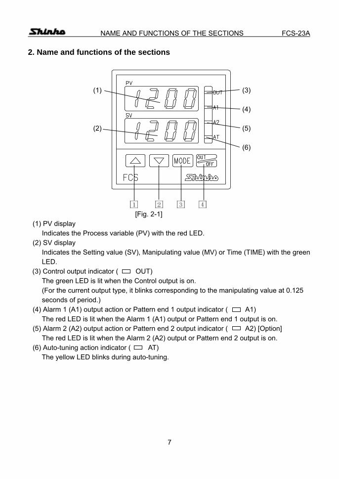
(1) PV display Indicates the Process variable (PV) with the red LED.
(2) SV display Indicates the Setting value (SV), Manipulating value (MV) or Time (TIME) with the green LED.
(3) Control output indicator ( OUT) The green LED is lit when the Control output is on. (For the current output type, it blinks corresponding to the manipulating value at 0.125 seconds of period.)
(4) Alarm 1 (A1) output action or Pattern end 1 output indicator ( A1) The red LED is lit when the Alarm 1 (A1) output or Pattern end 1 output is on.
(5) Alarm 2 (A2) output action or Pattern end 2 output indicator ( A2) [Option] The red LED is lit when the Alarm 2 (A2) output or Pattern end 2 output is on.
(6) Auto-tuning action indicator ( AT) The yellow LED blinks during auto-tuning.

8
NAME AND FUNCTIONS OF THE SECTIONS FCS-23A
Increase key : Increases the numeric value on the SV display during setting mode.
Decrease key : Decreases the numeric value on the SV display during setting mode.
Mode key : Selects the setting mode. OUT/OFF key : Performs the control output ON or OFF, or program control
Start or Stop. In any mode, if the key is pressed for approx. 1 second, the Control output OFF function will work. When the function is working, the function cannot be released. Even if the insrument power is turned off and on again, and the function is not released. To release the function, press the key for 1 second. The setting value is registered by pressing the key. In any setting item, if the key is pressed for approx. 3 seconds, the mode returns to the PV/SV display.

9
SETUP FCS-23A 3. Setup 3.1 Taking the internal assembly out
Before the power supply to this instrument is on, take the internal assembly out from the case by pushing the hook (bottom of the instrument) in the direction indicated by the arrow and holding the notches.
[Fig. 3.1-1] 3.2 Switch setting (multi-function)
Using a small slotted screwdriver and tweezers, set the Sensor input, Alarm 1 action, Alarm 2 action, Control action, Heating (reverse)/Cooling (direct) action, Alarm 1 and 2 standby functions, Unit / and Program starting form Auto/Manual change by rotary switch and DIP switch by the following procedure. The rotary switch A2 (SW301) is equipped only when the option A2 is applied.
Control action designation Alarm 2 action type designation Heating/Cooling action designation Alarm 1 action type designation Alarm 1 standby action designation Sensor input designation Alarm 2 standby action designation
/ designation Sensor input designation Program start Auto/Manual designation [Fig. 3.2-1]
DIP switch
Rotary switch
10
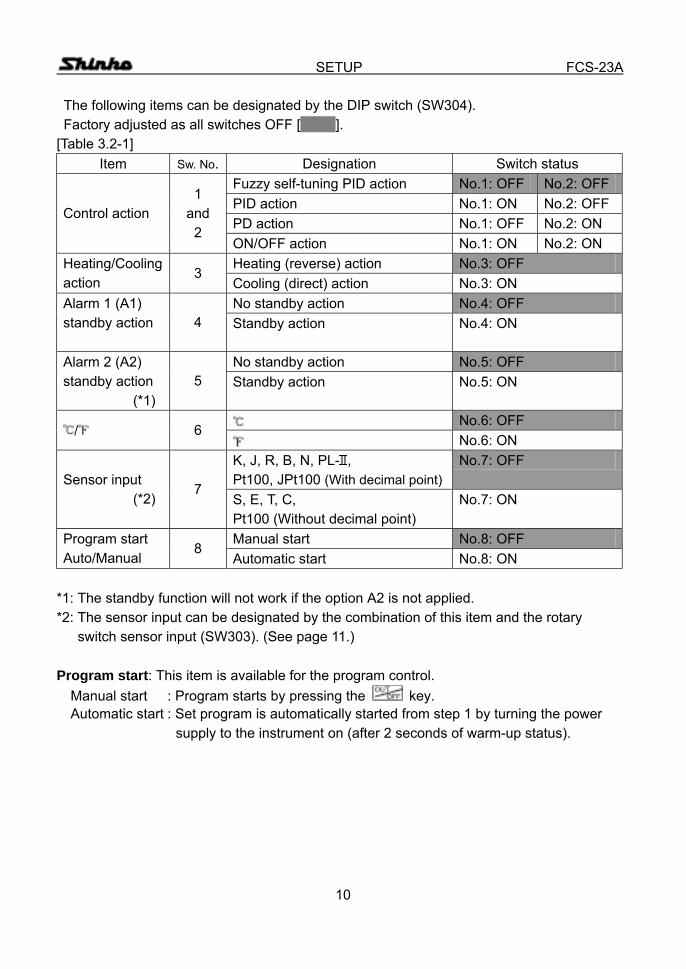
SETUP FCS-23A The following items can be designated by the DIP switch (SW304). Factory adjusted as all switches OFF [ ]. [Table 3.2-1]
Item Sw. No. Designation Switch status Fuzzy self-tuning PID action No.1: OFF No.2: OFF PID action No.1: ON No.2: OFF PD action No.1: OFF No.2: ON
Control action 1
and 2
ON/OFF action No.1: ON No.2: ON Heating (reverse) action No.3: OFF Heating/Cooling
action 3
Cooling (direct) action No.3: ON No standby action No.4: OFF Alarm 1 (A1)
standby action
4 Standby action No.4: ON
No standby action No.5: OFF Alarm 2 (A2) standby action
(*1) 5 Standby action No.5: ON
No.6: OFF / 6
No.6: ON K, J, R, B, N, PL- , Pt100, JPt100 (With decimal point)
No.7: OFF Sensor input
(*2) 7
S, E, T, C, Pt100 (Without decimal point)
No.7: ON
Manual start No.8: OFF Program start Auto/Manual
8 Automatic start No.8: ON
*1: The standby function will not work if the option A2 is not applied. *2: The sensor input can be designated by the combination of this item and the rotary switch sensor input (SW303). (See page 11.) Program start: This item is available for the program control.
Manual start : Program starts by pressing the key. Automatic start : Set program is automatically started from step 1 by turning the power supply to the instrument on (after 2 seconds of warm-up status).

11
SETUP FCS-23A
Select the sensor type by rotary switch sensor input (SW303). Factory adjusted as K, [ ].
[Table 3.2-2]
Rotary Sw. No.
DIP Sw. No. 7
Type of sensor
Scale range
0 OFF K -200 to 1370 -320 to 2500
1 OFF J -200 to 1000 -320 to 1800
2 OFF R 0 to 1760 0 to 3200
3 OFF B 0 to 1820 0 to 3300
4 OFF PL- 0 to 1390 0 to 2500
5 OFF N 0 to 1300 0 to 2300
6 OFF Pt100 -199.9 to 850.0 -199.9 to 999.9
7 OFF JPt100 -199.9 to 500.0 -199.9 to 900.0
0 ON S 0 to 1760 0 to 3200
1 ON E 0 to 1000 0 to 1800
2 ON T -199.9 to 400.0 -199.9 to 750.0
3 ON C (W/Re5-26) 0 to 2315 0 to 4200
7 ON Pt100 -200 to 850 -320 to 1560
12
SETUP FCS-23A
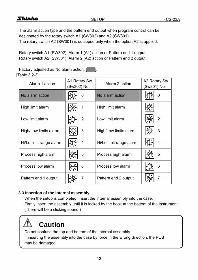
The alarm action type and the pattern end output when program control can be designated by the rotary switch A1 (SW302) and A2 (SW301). The rotary switch A2 (SW301) is equipped only when the option A2 is applied. Rotary switch A1 (SW302): Alarm 1 (A1) action or Pattern end 1 output. Rotary switch A2 (SW301): Alarm 2 (A2) action or Pattern end 2 output. Factory adjusted as No alarm action, [ ].
[Table 3.2-3]
Alarm 1 action A1 Rotary Sw. (Sw302) No.
Alarm 2 action A2 Rotary Sw. (Sw301) No.
No alarm action 0 No alarm action 0
High limit alarm 1 High limit alarm 1
Low limit alarm 2 Low limit alarm 2
High/Low limits alarm 3 High/Low limits alarm 3
Hi/Lo limit range alarm 4 Hi/Lo limit range alarm 4
Process high alarm 5 Process high alarm 5
Process low alarm 6 Process low alarm 6
Pattern end 1 output 7 Pattern end 2 output 7
3.3 Insertion of the internal assembly
When the setup is completed, insert the internal assembly into the case. Firmly insert the assembly until it is locked by the hook at the bottom of the instrument. (There will be a clicking sound.)
Caution Do not confuse the top and bottom of the internal assembly. If inserting the assembly into the case by force in the wrong direction, the PCB may be damaged.

13
OPERATIONS FCS-23A 4. Operations 4.1 Operating flow chart
Instrument power ON Warm-up status (For approx. 2s, displays as shown on page 15.) Control output OFF function
PV/SV display mode Output manipulating value Step rest time *1
+ + 3s [Main setting mode] [Sub setting mode] [Auxiliary function setting mode 1] Main setting Setting value memory No. selection Setting value lock PV PV designation Auto-tuning Perform/Cancel PV *2 PV Main setting value Proportional band setting high limit setting PV PV
Integral time setting Main setting value PV low limit setting
Derivative time setting PV PV Sensor correcting Proportional cycle setting value setting
PV PV Manual reset setting Instrument number
PV setting Alarm 1 (A1) setting PV
PV Transfer rate selection Alarm 2 (A2) setting PV PV Communication protocol
Loop break alarm time setting selection PV PV Loop break alarm span setting PV
3s
1s
14
OPERATIONS FCS-23A
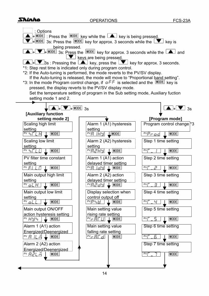
: Options + : Press the key while the key is being pressed. + 3s: Press the key for approx. 3 seconds while the key is
being pressed. + + 3s: Press the key for approx. 3 seconds while the and
keys are being pressed. + 3s : Pressing the key, press the key for approx. 3 seconds.
*1: Step rest time is indicated only during program control. *2: If the Auto-tuning is performed, the mode reverts to the PV/SV display. If the Auto-tuning is released, the mode will move to “Proportional band setting”. *3: In the mode Program control change, if is selected and the key is
pressed, the display reverts to the PV/SV display mode. Set the temperature setting of program in the Sub setting mode, Auxiliary fuction setting mode 1 and 2. + + 3s + 3s
[Auxiliary function setting mode 2] [Program mode]
Scaling high limit Alarm 1 (A1) hysteresis Program control change *3 setting setting PV PV PV Scaling low limit Alarm 2 (A2) hysteresis Step 1 time setting setting setting PV PV PV PV filter time constant Alarm 1 (A1) action Step 2 time setting setting delayed timer setting PV PV PV Main output high limit Alarm 2 (A2) action Step 3 time setting setting delayed timer setting PV PV PV Main output low limit Display selection when Step 4 time setting setting control output off PV PV PV Main output ON/OFF Main setting value Step 5 time setting action hysteresis setting rising rate setting PV PV PV Alarm 1 (A1) action Main setting value Step 6 time setting Energized/Deenergized falling rate setting PV PV PV Alarm 2 (A2) action Step 7 time setting Energized/Deenergized PV PV
15
OPERATIONS (PV/SV display mode) FCS-23A 4.2 Operations
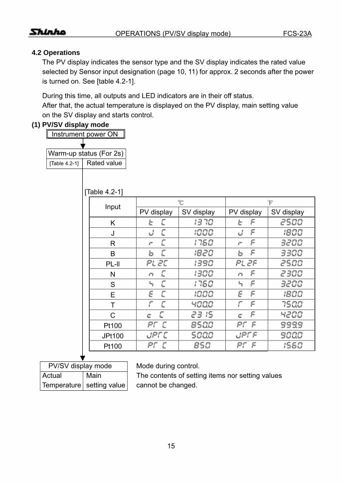
The PV display indicates the sensor type and the SV display indicates the rated value selected by Sensor input designation (page 10, 11) for approx. 2 seconds after the power is turned on. See [table 4.2-1].
During this time, all outputs and LED indicators are in their off status. After that, the actual temperature is displayed on the PV display, main setting value on the SV display and starts control.
(1) PV/SV display mode Instrument power ON Warm-up status (For 2s)
[Table 4.2-1] Rated value
[Table 4.2-1]
Input PV display SV display PV display SV display
K J R B
PL-ll N S E T C
Pt100 JPt100 Pt100
PV/SV display mode Mode during control.
Actual Main The contents of setting items nor setting values Temperature setting value cannot be changed.
16
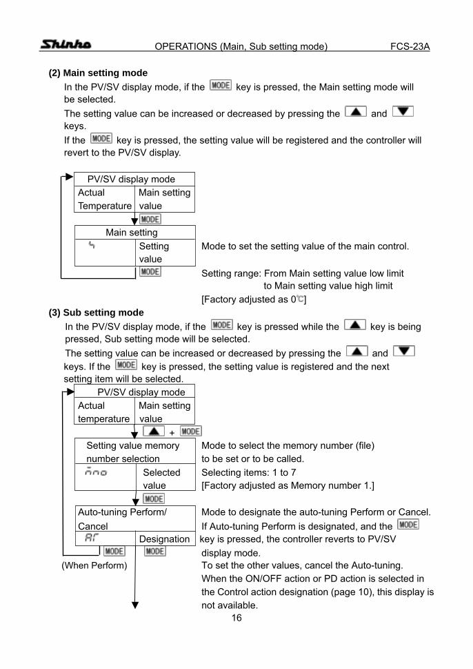
OPERATIONS (Main, Sub setting mode) FCS-23A (2) Main setting mode
In the PV/SV display mode, if the key is pressed, the Main setting mode will be selected. The setting value can be increased or decreased by pressing the and keys. If the key is pressed, the setting value will be registered and the controller will revert to the PV/SV display.
PV/SV display mode
Actual Main setting Temperature value
Main setting Setting Mode to set the setting value of the main control.
value Setting range: From Main setting value low limit to Main setting value high limit [Factory adjusted as 0 ]
(3) Sub setting mode In the PV/SV display mode, if the key is pressed while the key is being pressed, Sub setting mode will be selected. The setting value can be increased or decreased by pressing the and keys. If the key is pressed, the setting value is registered and the next setting item will be selected.
PV/SV display mode Actual Main setting temperature value
+ Setting value memory Mode to select the memory number (file) number selection to be set or to be called. Selected Selecting items: 1 to 7 value [Factory adjusted as Memory number 1.]
Auto-tuning Perform/ Mode to designate the auto-tuning Perform or Cancel. Cancel If Auto-tuning Perform is designated, and the Designation key is pressed, the controller reverts to PV/SV
display mode. (When Perform) To set the other values, cancel the Auto-tuning.
When the ON/OFF action or PD action is selected in the Control action designation (page 10), this display is not available.
17
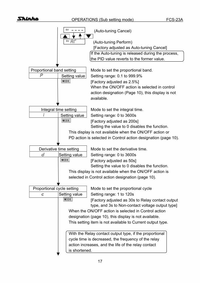
OPERATIONS (Sub setting mode) FCS-23A SV (Auto-tuning Cancel)
SV (Auto-tuning Perform) [Factory adjusted as Auto-tuning Cancel] If the Auto-tuning is released during the process, the PID value reverts to the former value. Proportional band setting Mode to set the proportional band.
Setting value Setting range: 0.1 to 999.9% [Factory adjusted as 2.5%]
When the ON/OFF action is selected in control action designation (Page 10), this display is not available.
Integral time setting Mode to set the integral time. Setting value Setting range: 0 to 3600s [Factory adjusted as 200s]
Setting the value to 0 disables the function. This display is not available when the ON/OFF action or PD action is selected in Control action designation (page 10).
Derivative time setting Mode to set the derivative time. Setting value Setting range: 0 to 3600s
[Factory adjusted as 50s] Setting the value to 0 disables the function. This display is not available when the ON/OFF action is selected in Control action designation (page 10). Proportional cycle setting Mode to set the proportional cycle Setting value Setting range: 1 to 120s
[Factory adjusted as 30s to Relay contact output type, and 3s to Non-contact voltage output type] When the ON/OFF action is selected in Control action designation (page 10), this display is not available. This setting item is not available to Current output type. With the Relay contact output type, if the proportional cycle time is decreased, the frequency of the relay action increases, and the life of the relay contact is shortened.
18
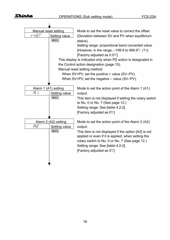
OPERATIONS (Sub setting mode) FCS-23A Manual reset setting Mode to set the reset value to correct the offset Setting value (Deviation between SV and PV when equilibrium status). Setting range: proportional band converted value [However, in the range, –199.9 to 999.9 ( )] [Factory adjusted as 0.0 ] This display is indicated only when PD action is designated in the Control action designation (page 10). Manual reset setting method: When SV>PV, set the positive + value (SV–PV). When SV<PV, set the negative – value (SV–PV). Alarm 1 (A1) setting Mode to set the action point of the Alarm 1 (A1) Setting value output. This item is not displayed if setting the rotary switch to No. 0 or No. 7 (See page 12.) Setting range: See [table 4.2-2]. [Factory adjusted as 0 ]
Alarm 2 (A2) setting Mode to set the action point of the Alarm 2 (A2) Setting value output. This item is not displayed if the option [A2] is not applied or even if it is applied, when setting the rotary switch to No. 0 or No. 7 (See page 12.) Setting range: See [table 4.2-2]. [Factory adjusted as 0 ]
19
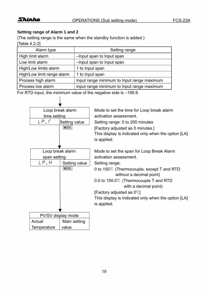
OPERATIONS (Sub setting mode) FCS-23A Setting range of Alarm 1 and 2 (The setting range is the same when the standby function is added.) [Table 4.2-2]
Alarm type Setting range High limit alarm –Input span to Input span Low limit alarm –Input span to Input span High/Low limits alarm 1 to Input span High/Low limit range alarm 1 to Input span Process high alarm Input range minimum to Input range maximum Process low alarm Input range minimum to Input range maximum
For RTD input, the minimum value of the negative side is –199.9.
Loop break alarm Mode to set the time for Loop break alarm time setting activation assessment.
Setting value Setting range: 0 to 200 minutes [Factory adjusted as 0 minutes.]
This display is indicated only when the option [LA] is applied. Loop break alarm Mode to set the span for Loop Break Alarm
span setting activation assessment. Setting value Setting range:
0 to 150 (Thermocouple, except T and RTD without a decimal point) 0.0 to 150.0 (Thermocouple T and RTD with a decimal point) [Factory adjusted as 0 ] This display is indicated only when the option [LA] is applied.
PV/SV display mode Actual Main setting Temperature value
20
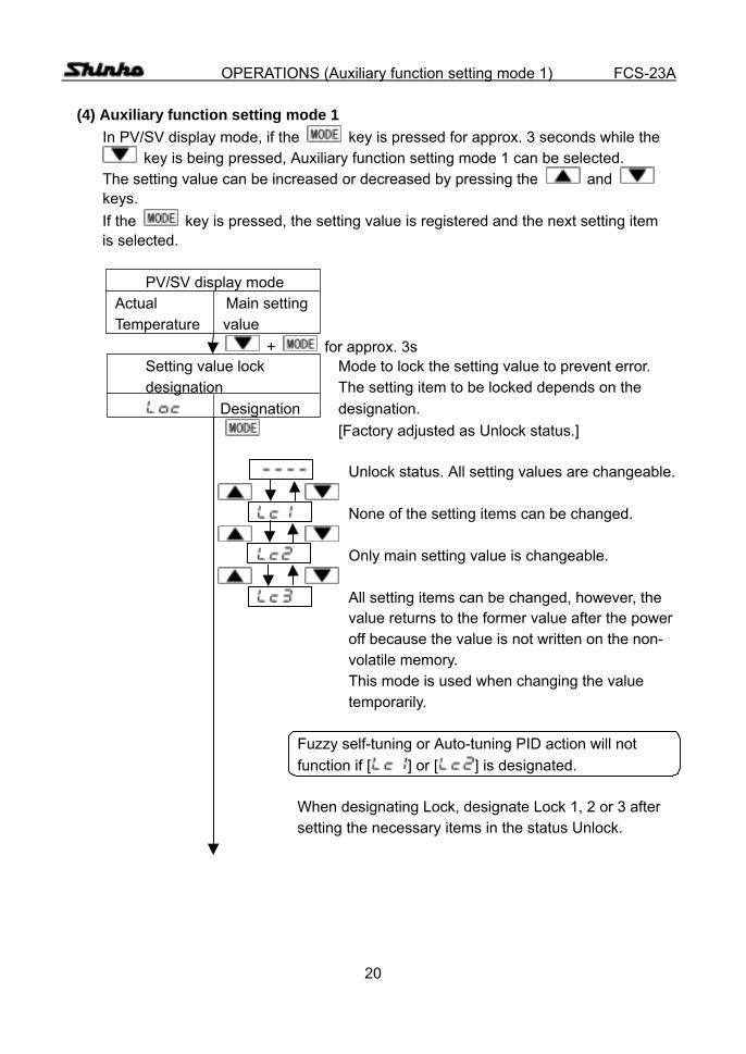
OPERATIONS (Auxiliary function setting mode 1) FCS-23A (4) Auxiliary function setting mode 1
In PV/SV display mode, if the key is pressed for approx. 3 seconds while the key is being pressed, Auxiliary function setting mode 1 can be selected.
The setting value can be increased or decreased by pressing the and keys. If the key is pressed, the setting value is registered and the next setting item is selected.
PV/SV display mode Actual Main setting Temperature value + for approx. 3s Setting value lock Mode to lock the setting value to prevent error. designation The setting item to be locked depends on the Designation designation. [Factory adjusted as Unlock status.] Unlock status. All setting values are changeable.
None of the setting items can be changed.
Only main setting value is changeable.
All setting items can be changed, however, the value returns to the former value after the power off because the value is not written on the non- volatile memory. This mode is used when changing the value temporarily. Fuzzy self-tuning or Auto-tuning PID action will not function if [ ] or [ ] is designated. When designating Lock, designate Lock 1, 2 or 3 after setting the necessary items in the status Unlock.
21
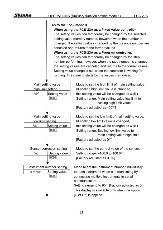
OPERATIONS (Auxiliary function setting mode 1) FCS-23A As to the Lock mode 3 When using the FCS-23A as a Fixed value controller. The setting values can temporarily be changed by the selected setting value memory number, however, when the number is changed, the setting values changed by the previous number are canceled and returns to the former values. When using the FCS-23A as a Program controller. The setting values can temporarily be changed by the step number performing, however, when the step number is changed, the setting values are canceled and returns to the former values. Setting value change is null when the controller is waiting for running. The running starts by the values memorized. Main setting value Mode to set the high limit of main setting value. high limit setting (If scaling high limit value is changed,
Setting value this setting value will be changed as well.) Setting range: Main setting value low limit to scaling high limit value [Factory adjusted as 400 ]
Main setting value Mode to set the low limit of main setting value. low limit setting (If scaling low limit value is changed,
Setting value this setting value will be changed as well.) Setting range: Scaling low limit value to
main setting value high limit [Factory adjusted as 0 ]
Sensor correction setting Mode to set the correct value of the sensor.
Setting value Setting range: –100.0 to 100.0 [Factory adjusted as 0.0 ]
Instrument number setting Mode to set the Instrument number individually Setting value to each instrument when communicating by connecting multiple instruments in serial communication. Setting range: 0 to 95 [Factory adjusted as 0] This display is available only when the option [C or C5] is applied.

22
OPERATIONS (Auxiliary function setting mode 1) FCS-23A
Transfer rate selection Mode to select a communication transfer rate Selection to meet the rate of the host computer.
[Factory adjusted as 9600bps] 2400bps
4800bps
9600bps
19200bps This display is available only when the option [C or C5] is applied. Communication protocol Mode to select a communication protocol
selection between the FCS-23A and the host computer. Selection [Factory adjusted as ]
Shinko standard protocol
Based on Modbus, ASCII mode This display is available only when the option [C or C5] is applied. PV/SV display mode Actual Main setting Temperature value

23
OPERATIONS (Auxiliary function setting mode 2) FCS-23A (5) Auxiliary function setting mode 2
In PV/SV display mode, if the key is pressed for approx. 3 seconds while the and keys are being pressed, Auxiliary function setting mode 2 can be
selected. The setting value can be increased or decreased by pressing the and keys. If the key is pressed, the setting value is registered and the next setting item is selected.
PV/SV display mode Actual Main setting Temperature value + + for approx. 3s Scaling high limit setting Mode to set the high limit value of the scaling. Setting value If scaling high limit value is changed, main setting high limit value will be changed to the scaling high limit value as well. Setting range: Scaling low limit value to input range maximum value [Factory adjusted as 1370 ] Scaling low limit setting Mode to set the low limit value of the scaling. Setting value If scaling low limit value is changed, main setting
low limit value will be changed to the scaling low limit value as well. Setting range: Input range minimum value to scaling high limit value [Factory adjusted as –200 ] PV filter time constant Mode to suppress the PV fluctuation caused by Setting such as disturbance.
Setting value Set the value larger by degrees, and find the setting value at which the value does not fluctuate. If the value is set too large, it affects control result due to the delay of response. Setting range: 0.0 to 10.0s [Factory adjusted as 0.0s]
24
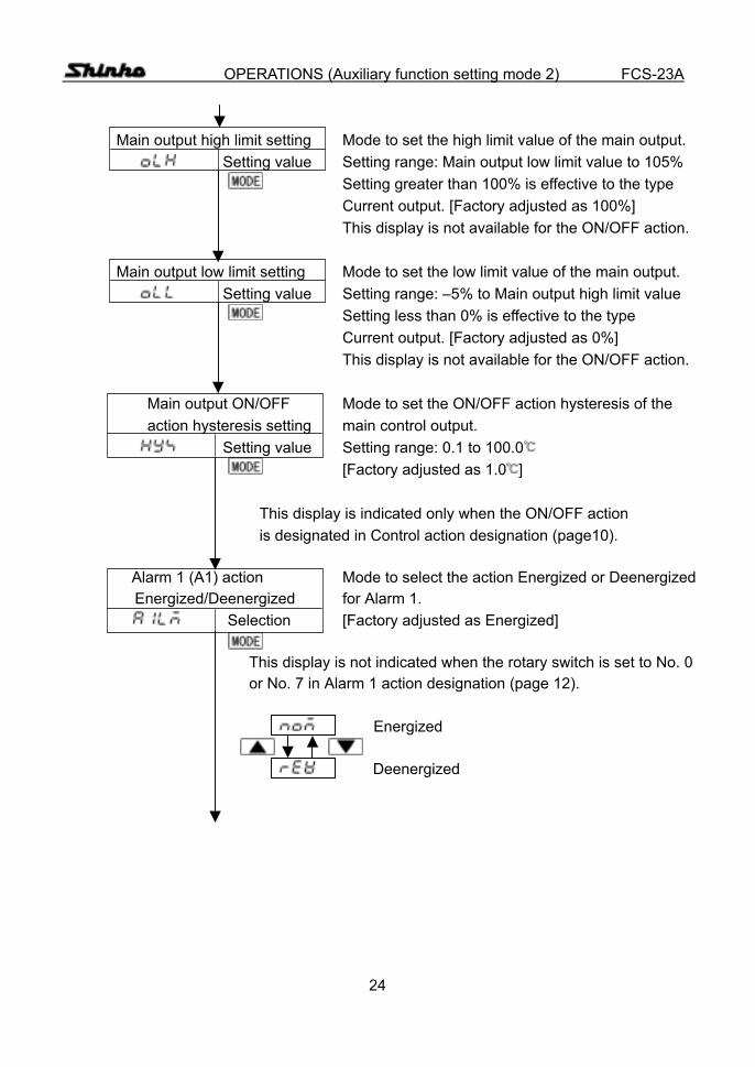
OPERATIONS (Auxiliary function setting mode 2) FCS-23A Main output high limit setting Mode to set the high limit value of the main output. Setting value Setting range: Main output low limit value to 105% Setting greater than 100% is effective to the type Current output. [Factory adjusted as 100%] This display is not available for the ON/OFF action. Main output low limit setting Mode to set the low limit value of the main output. Setting value Setting range: –5% to Main output high limit value Setting less than 0% is effective to the type Current output. [Factory adjusted as 0%] This display is not available for the ON/OFF action. Main output ON/OFF Mode to set the ON/OFF action hysteresis of the action hysteresis setting main control output. Setting value Setting range: 0.1 to 100.0 [Factory adjusted as 1.0 ] This display is indicated only when the ON/OFF action is designated in Control action designation (page10). Alarm 1 (A1) action Mode to select the action Energized or Deenergized
Energized/Deenergized for Alarm 1. Selection [Factory adjusted as Energized] This display is not indicated when the rotary switch is set to No. 0 or No. 7 in Alarm 1 action designation (page 12). Energized Deenergized

25
OPERATIONS (Auxiliary function setting mode 2) FCS-23A Alarm 2 (A2) action Mode to select the action Energized or Deenergized
Energized/Deenergized for Alarm 2. Selection [Factory adjusted as Energized] This display is not indicated when the rotary switch is set to No. 0 or No. 7 in Alarm 2 action designation (page 14), or the option [A2] is not applied. Selection items: The same as those of the alarm 1 (A1) action Energized/Deenergized selection. Alarm 1 hysteresis setting Mode to set the hysteresis value for Alarm 1. Setting value Setting range: 0.1 to 100.0 [Factory adjusted as 1.0 ] This display is not indicated when the rotary switch is set to No. 0 or No. 7 in Alarm 1 action designation (page 12). Alarm 2 hysteresis setting Mode to set the hysteresis value for Alarm 2. Setting value Setting range: 0.1 to 100.0 [Factory adjusted as 1.0 ] This display is not indicated when the option [A2] is not applied and when the rotary switch is set to No. 0 or No. 7 in Alarm 2 action designation (page 12) even if the option [A2] is applied. Alarm 1 (A1) action Mode to set the action delayed timer for Alarm 1. delayed timer setting Setting range: 0 to 9999s
Setting value [Factory adjusted as 0s] Alarm output is turned on when the setting time has passed after the input gets into the alarm output range. This display is not indicated if the rotary switch is set to No. 0 or No. 7 in Alarm 1 action designation (page 12).
26
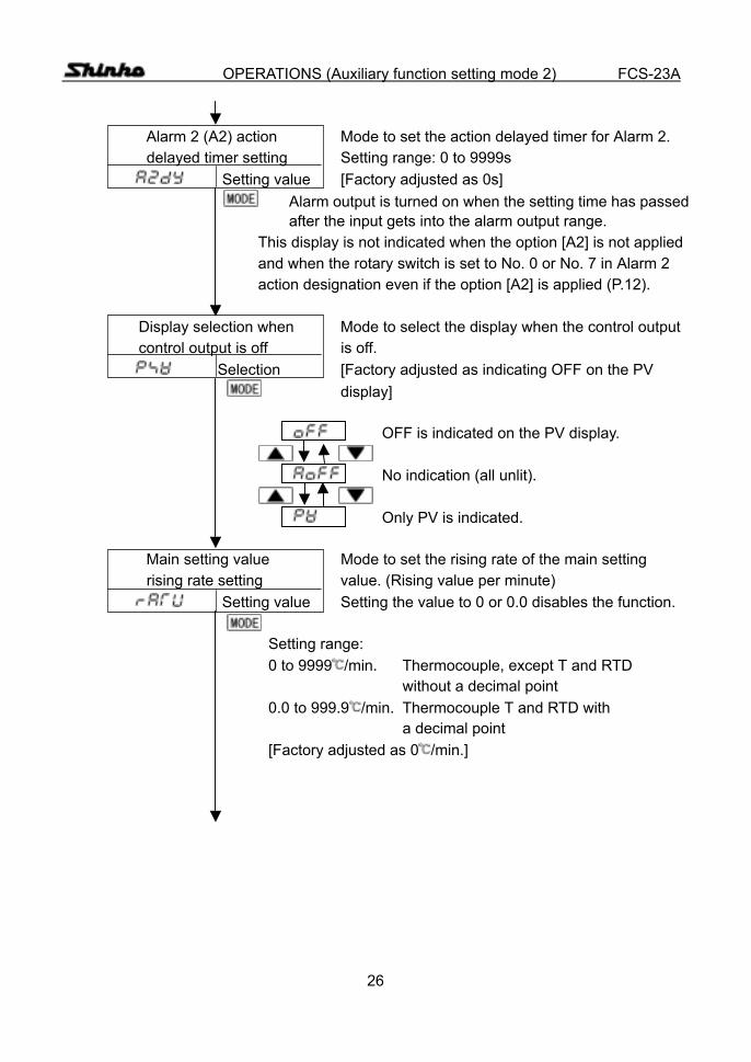
OPERATIONS (Auxiliary function setting mode 2) FCS-23A Alarm 2 (A2) action Mode to set the action delayed timer for Alarm 2. delayed timer setting Setting range: 0 to 9999s
Setting value [Factory adjusted as 0s] Alarm output is turned on when the setting time has passed after the input gets into the alarm output range. This display is not indicated when the option [A2] is not applied and when the rotary switch is set to No. 0 or No. 7 in Alarm 2 action designation even if the option [A2] is applied (P.12). Display selection when Mode to select the display when the control output control output is off is off.
Selection [Factory adjusted as indicating OFF on the PV display] OFF is indicated on the PV display.
No indication (all unlit).
Only PV is indicated. Main setting value Mode to set the rising rate of the main setting rising rate setting value. (Rising value per minute)
Setting value Setting the value to 0 or 0.0 disables the function. Setting range: 0 to 9999 /min. Thermocouple, except T and RTD without a decimal point 0.0 to 999.9 /min. Thermocouple T and RTD with a decimal point [Factory adjusted as 0 /min.]
27
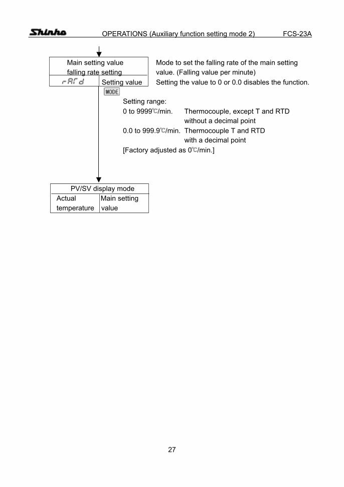
OPERATIONS (Auxiliary function setting mode 2) FCS-23A Main setting value Mode to set the falling rate of the main setting falling rate setting value. (Falling value per minute)
Setting value Setting the value to 0 or 0.0 disables the function. Setting range: 0 to 9999 /min. Thermocouple, except T and RTD without a decimal point 0.0 to 999.9 /min. Thermocouple T and RTD with a decimal point [Factory adjusted as 0 /min.] PV/SV display mode Actual Main setting temperature value
28
OPERATIONS (Program mode) FCS-23A (6) Program mode
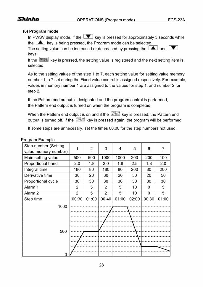
In PV/SV display mode, if the key is pressed for approximately 3 seconds while the key is being pressed, the Program mode can be selected. The setting value can be increased or decreased by pressing the and keys. If the key is pressed, the setting value is registered and the next setting item is selected.
As to the setting values of the step 1 to 7, each setting value for setting value memory number 1 to 7 set during the Fixed value control is assigned respectively. For example, values in memory number 1 are assigned to the values for step 1, and number 2 for step 2.
If the Pattern end output is designated and the program control is performed, the Pattern end output is turned on when the program is completed.
When the Pattern end output is on and if the key is pressed, the Pattern end output is turned off. If the key is pressed again, the program will be performed.
If some steps are unnecesary, set the times 00.00 for the step numbers not used.
Program Example Step number (Setting value memory number)
1 2 3 4 5 6 7
Main setting value 500 500 1000 1000 200 200 100 Proportional band 2.0 1.8 2.0 1.8 2.5 1.8 2.0 Integral time 180 80 180 80 200 80 200 Derivative time 30 20 30 20 50 20 50 Proportional cycle 30 30 30 30 30 30 30 Alarm 1 2 5 2 5 10 0 5 Alarm 2 2 5 2 5 10 0 5 Step time 00:30 01:00 00:40 01:00 02:00 00:30 01:00
0
500
1000

29
OPERATIONS (Program mode) FCS-23A
PV/SV display mode Actual Main setting temperature value
+ for approx. 3s Program control change Control form is changed between Fixed value Setting value of and Program. fixed value control
In Fixed value control, if the key is pressed, (Fixed value the mode will revert to the PV/SV display. control) Fixed value control
Program control
[Factory adjusted as Fixed value control]
Following dislay is available only when Program control.
Step 1 Time setting Mode to set the Time for step 1. Setting value 00.00
Minute indication Hour indication For example, when setting 1 hour 58 minutes, set as [ ]. Setting range: 00.00 to 99.59 [Factory adjusted as 00.00]
Step 2 Time setting Mode to set the Time for step 2. Setting value [The setting range and the factory adjusted value
are the same as Step 1.]
Step 3 Time setting Mode to set the Time for step 3. Setting value [The setting range and the factory adjusted value
are the same as Step 1.]
Step 4 Time setting Mode to set the Time for step 4. Setting value [The setting range and the factory adjusted value
are the same as Step 1.]
30
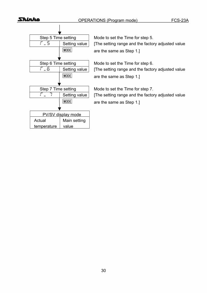
OPERATIONS (Program mode) FCS-23A
Step 5 Time setting Mode to set the Time for step 5. Setting value [The setting range and the factory adjusted value
are the same as Step 1.]
Step 6 Time setting Mode to set the Time for step 6. Setting value [The setting range and the factory adjusted value
are the same as Step 1.]
Step 7 Time setting Mode to set the Time for step 7. Setting value [The setting range and the factory adjusted value
are the same as Step 1.]
PV/SV display mode Actual Main setting temperature value
31
OPERATIONS (Control output OFF function) FCS-23A
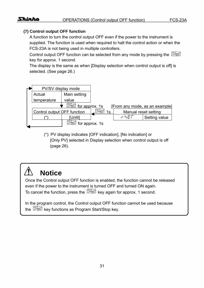
(7) Control output OFF function A function to turn the control output OFF even if the power to the instrument is supplied. The function is used when required to halt the control action or when the FCS-23A is not being used in multiple controllers. Control output OFF function can be selected from any mode by pressing the key for approx. 1 second. The display is the same as when [Display selection when control output is off] is selected. (See page 26.)
PV/SV display mode Actual Main setting temperature value
for approx. 1s [From any mode, as an example] Control output OFF function 1s Manual reset setting (*) [Unlit] Setting value for approx. 1s
(*): PV display indicates [OFF indication], [No indication] or [Only PV] selected in Display selection when control output is off
(page 26).
Notice Once the Control output OFF function is enabled, the function cannot be released even if the power to the instrument is turned OFF and turned ON again. To cancel the function, press the key again for approx. 1 second. In the program control, the Control output OFF function cannot be used because the key functions as Program Start/Stop key.

32
OPERATIONS (Manipulating value and Step time indication ) FCS-23A (8) Output manipulating value and Step rest time indication mode In the PV/SV display mode, press the key for approx. 3 seconds. The display will be changed to main setting mode in the process, however, keep
pressing it until the Output manipulating value is displayed. If the key is pressed again, the mode reverts to the PV/SV display. During program control, if the key is pressed in Output manipulating value indication, the Step rest time indication will be selected. If the key is pressed again, the mode reverts to the PV/SV display.
PV/SV display mode
Actual Main setting temperature value
for approx. 3s Output manipulating value indication mode
Actual manipulating Manipulating value is indicated on the SV display temperature value by the blinking the decimal point.
(Fixed value (Program control) control)
Step rest time indication Actual Step Step rest time is indicated on the SV display. temperature rest time

33
SETTING VALUE MEMORY FUNCTION FCS-23A 5. Setting value memory number external selection [Option code: SM]
If the option SM is applied, setting value memory number 2 can be selected by external operation. The option SM cannot be applied in combination with option A2, LA, C or C5. ● Wiring connection of setting value memory number external selection
The Setting value memory number 2 can be selected by shorting between 1 and 3. If Setting value memory number 2 is selected by the Open collector, connect the pin No.1 to the collector and the pin No. 3 to the emitter.
When the Setting value memory number 2 is selected by external operation, the number cannot be selected by front key operation. Memory number cannot be changed during setting mode or PID auto-tuning.
5
4
3
9
8
10
1
2 7
6
1( )
2(NC)
3( )
NC
(Color of wire: Red)
(Color of wire: Blue) 1
2
3