Embed Size (px)
Citation preview
1
Digital ElectronicsPart III – Practical Labs
Dr. I. J. Wassell
Hardware Labs
2
Introduction
• In the hardware lab you will:– Construct logic circuits on breadboards
and test them
– Design logic circuits and implement them using
• Logic gates (SSI) and counter chips (MSI) logic
• Memory devices (VLSI)
• Programmable array logic (PAL) type devices –specifically Generic array logic (GAL)
Introduction
• In the labs you will make use of the self-
contained Prototyping Box
• Contains:
– Breadboard to build the circuits on
– A power supply (PSU) – 5V
– Clock signal (square wave) generator
– Switches
• Conventional push switches
• Ones giving logic outputs for input to circuits
– LEDs and displays for showing outputs
3
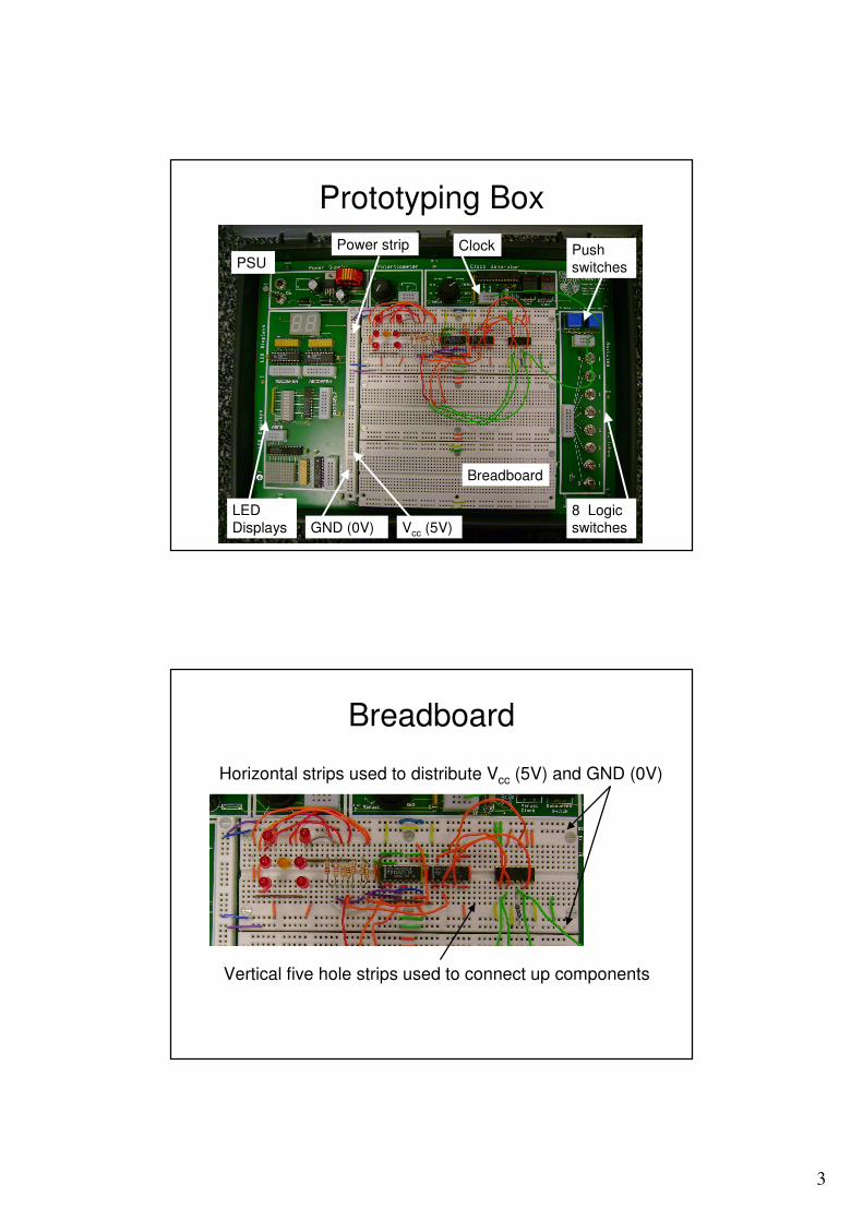
Prototyping Box
PSU
Power strip
Breadboard
Push
switches
8 Logic
switches
LED
Displays GND (0V) Vcc (5V)
Clock
Breadboard
Horizontal strips used to distribute Vcc (5V) and GND (0V)
Vertical five hole strips used to connect up components
4
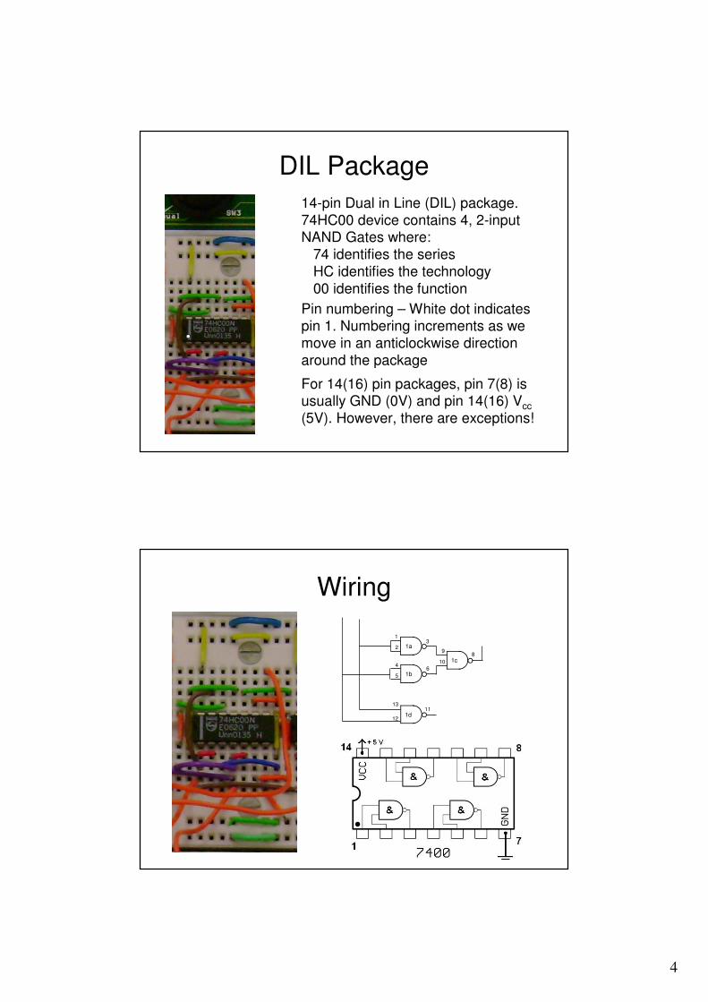
DIL Package
14-pin Dual in Line (DIL) package.
74HC00 device contains 4, 2-input NAND Gates where:
74 identifies the series
HC identifies the technology
00 identifies the function
Pin numbering – White dot indicates pin 1. Numbering increments as we
move in an anticlockwise direction
around the package
For 14(16) pin packages, pin 7(8) is usually GND (0V) and pin 14(16) Vcc
(5V). However, there are exceptions!
Wiring
1d
1
1a
1b
1c
23
4
5
6
9
10
8
12
1311