Embed Size (px)
Citation preview

Digital Control IC for Interleaved PFCsRosario AttanasioApplications Manager STMicroelectronics

Presentation Outline
• PFC Basics
• Interleaved PFC Concept
• Analog Vs Digital Control
• The STNRGPF01 Digital Controller• Main Functions• Edesign suite GUI
• Application Example: • 3kW Three channel Interleaved PFC• Performance Evaluation
• Conclusions
2

Power Factor Correction 5
A PFC is the input stage of an AC/DC converter connected to the AC mains to address the need to limit energy consumption
A PFC pre-regulator placed between the bridge and the bulk capacitor draws a quasi-sinusoidal current from the mains, in-phase with the line voltage
Harmonic current emission is regulated by IEC 61000-3-2. Lighting requirements > 25W, SMPS & chargers > 75W
Maximize the energy delivery to load means to reduce the Total Harmonic Distortion (THD) and therefore maximize the Power Factor

Introduction to PFC 4
Kd= Distortion Factor Kϴ= Displacement Factor

Passive vs Active PFC 5
EMIFilter Rectifier PFC Main
Converter Load
SMPS Structure
• PFC stage can be “Passive” or “Active”. • Passive: bulky capacitors and inductors
• Active: high frequency topologies

Passive PFC Topologies 6
AC side inductor
DC side inductor
SR Bandpass filter
PR Bandstop filter
Harmonic Trap filter
LCD Rectifier

Active PFC Topologies• Main topologies for PFC stage:
• Boost (most used because it’s stepping-up the voltage)• Buck• Flyback• Cuk• Sepic
• Operation modes:• Continuous Conduction Mode (CCM) > 350W • Transition Mode (TM) <350W • Discontinuous Conduction Mode (DCM)
7

PFC – Control Technique 8
Type Strengths Weakness
Average current control Low distortion on input current Two control loops
Peak Current control Fast current correction High distortion on input current
Hysteresis Current control Fast current correctionLow distortion on input current Need two comparators

PFC – Interleaved Concept 9
+PFC
controller Phase1
Phase n
L1
LN
I1
In
Ic
M1
Mn
DC/DCor
DC/ACLoad

Example: 3kW iPFCSwitching frequency 100kHz
10
Core: EE70L= 150µHSize: h=70mm, W=66mm, D=31mmVolume=8.72 in3
Single Channel
Interleaved 3 Channels
45% Less!
Core: PQ3230L= 120µHSize: h=30mm, W=32mm, D=27mmVolume=1.58 in3
Total Volume=4.74 in3

Output Capacitor Ripple Current Reduction
RMS Current Reduction
11
Capacitors with higher ESR can be used Lower cost
0.50 1
0
0.5
1
%D
I 𝑐𝑐𝑐𝑐𝑐𝑐𝑐𝑐𝑁𝑁𝑐𝑐𝑁𝑁𝑁𝑁𝑁𝑁𝑁𝑁𝑁𝑁𝑁𝑁𝑁𝑁𝑁𝑁
Single Channel
Double Channel
Triple Channel

Digital vs Analog PFC Control 12
• Full digital control of PFC is already state of the art.
• More PFC topologies can be implemented
• More sophisticated control algorithms
Digital Control Analog Control
• Availability of ICs for PFCs from many manufacturers
• Cycle by cycle control loop
• High bandwidth
• Low Cost

The STNRGPF01: Overview 13
• TSSOP38 Package• Mixed Signal Control• Configurable By GUI

The STNRGPF01: Overview 14
• Semi-digital control • Analog current controller • Voltage controller, feed-forward compensation, multiplier, PWM clock generator and non-
time critical protection functions are implemented digitally.
• Interleaved boost PFC• Up to 3 interleaved channels• CCM, fixed frequency• Average current control, cycle-by-cycle• Inrush current control• Burst mode support• OCP, OVP and thermal protection• Soft start-up• Flexible phase-shedding strategy

STRNGPF01: Application Block Diagram 15

STNRGPF01: Voltage Loop 16
• Output Voltage Sensing
• Input Voltage Sensing
• Output Current Sensing
• ZVD Sensing
Internal control block scheme

STNRGPF01: Current Loop 17
Analog Current OP-Amp PI
Itot_ref
Itot_fb
Internal control block scheme
STNRGPF01: Driving and Interleaving 18
Internal control block scheme Interleaving operation (internal)
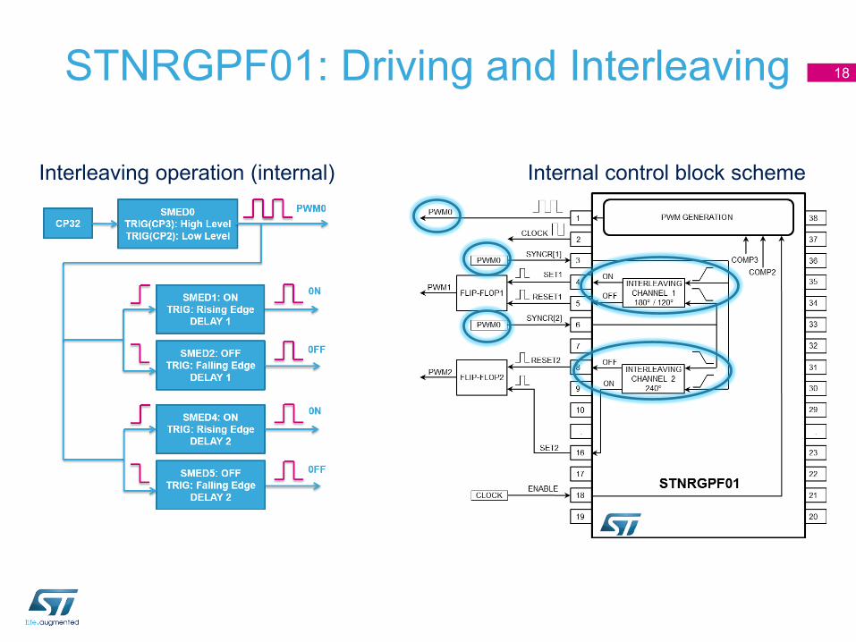
STNRGPF01 GUI: eDesign Suite Tool 19
Binary file generation
BoM + SCHEMATIC
eDesignSuite smart configurator for STNRGPF01
Build

• Load feed forward• Working frequency = 111kHz per channel• Thermal protection set at 120°C• Current protection set at 33A• Direct fan driving• Current reference realized by internal map (200 pt)
3kW Three Channels Interleaved PFC 20
High Power Density52W/in3!
• STNRGPF01 (Digital controller for PFC)• PM8834D (Double Channel low side driver)• ALTAIR05-800 (Off-line primary-sens. switch. reg.)• STW40N60M2 (MDmesh II Plus low Qg ) • STPSC1206 Schottky silicon carbide diode• TSV911 (High speed OP)• LMV358 (Standard OP)• M74HC132 (Quad NAND Gate)
Key Products
L=24,5 cm; W=11 cm; H=3,5 cm (including heatsink area)
• Pout = 3kW @ Vin = 230Vac; 1.5kW @ Vin = 110Vac• Vout = 400V• PF > 0.98 @ 20% load• THD < 5% @ 20% load• CCM with analog current control loop
(cycle by cycle regulation)• Input Voltage feed forward
The device performance have been evaluated developing a 3kW Three channels PFC.

Experimental Results: Steady State 21
Duty cycle Inductors current
PWM master

Experimental Results: Load Feed Forward 22
Input current
DC Bus voltage
The load feed forward when load step is applied reduces the over and under voltage of the output dc bus voltage!
Load step : 0W - 2kW
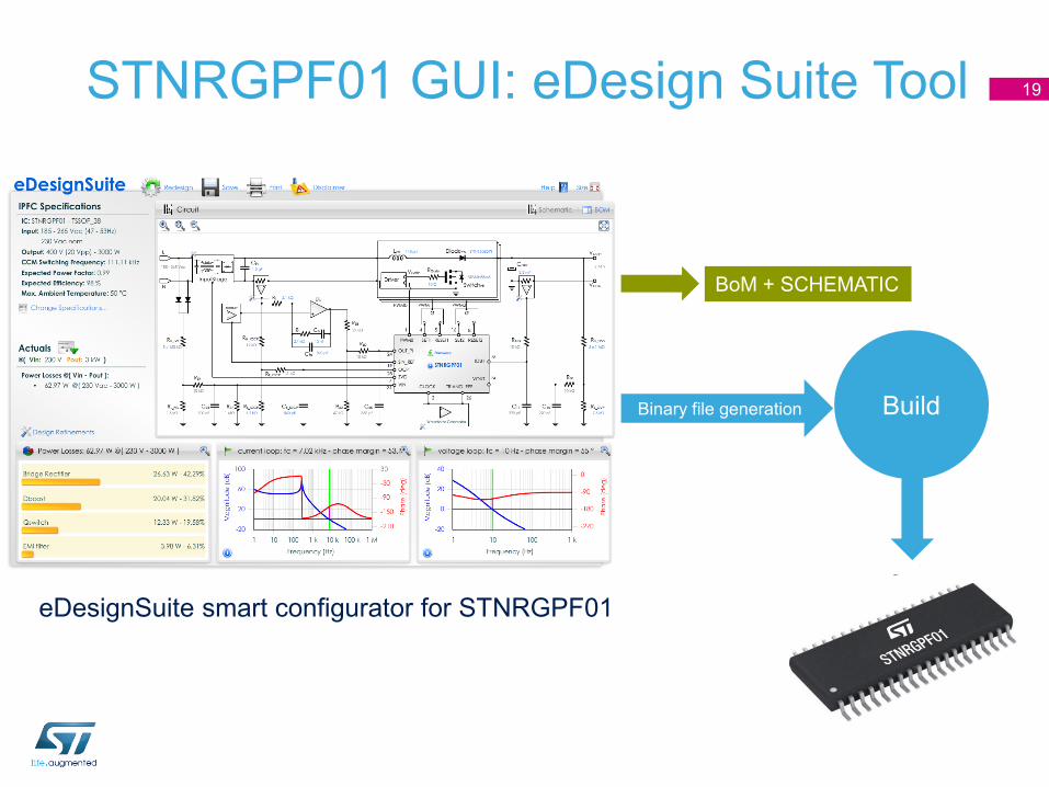
Experimental Results: Load Feed Forward 23
Input current
DC Bus voltage
The load feed forward when load step is applied reduces the over and under voltage of the output dc bus voltage!
Load step sequence: 0.4kW - 2kW - 0.4kW

Experimental Results: Load Feed Forward 24
Input current
DC Bus voltage
Load step sequence: 0W - 2kW - 0W
The PFC interrupts the Burst Mode to meet the load requirement and when load is disconnected it returns in Burst Mode.

Experimental ResultsEfficiency and ITHD%
25

Conclusions
• Interleaved PFC benefits include: the use of smaller components, better thermal performance, low current ripple
• The STNRGPF01 is a controller for CCM interleaved PFCs
• It supports up to three independent channels
• Cycle by Cycle current control allows fast dynamic response
• The STNRGPF01 can be easily and quickly configured using the eDesign Suite GUI resulting in reduced development time, lower development cost and faster time-to-market
26

27
Thank You!