Embed Size (px)
Citation preview
Digital power control with STNRG011
Digital Combo PFC+LLC Controller
High Integration for Efficient
Digital SMPS Design
Complete Evaluation Ecosystem
Advanced Power Supply Control
Topics
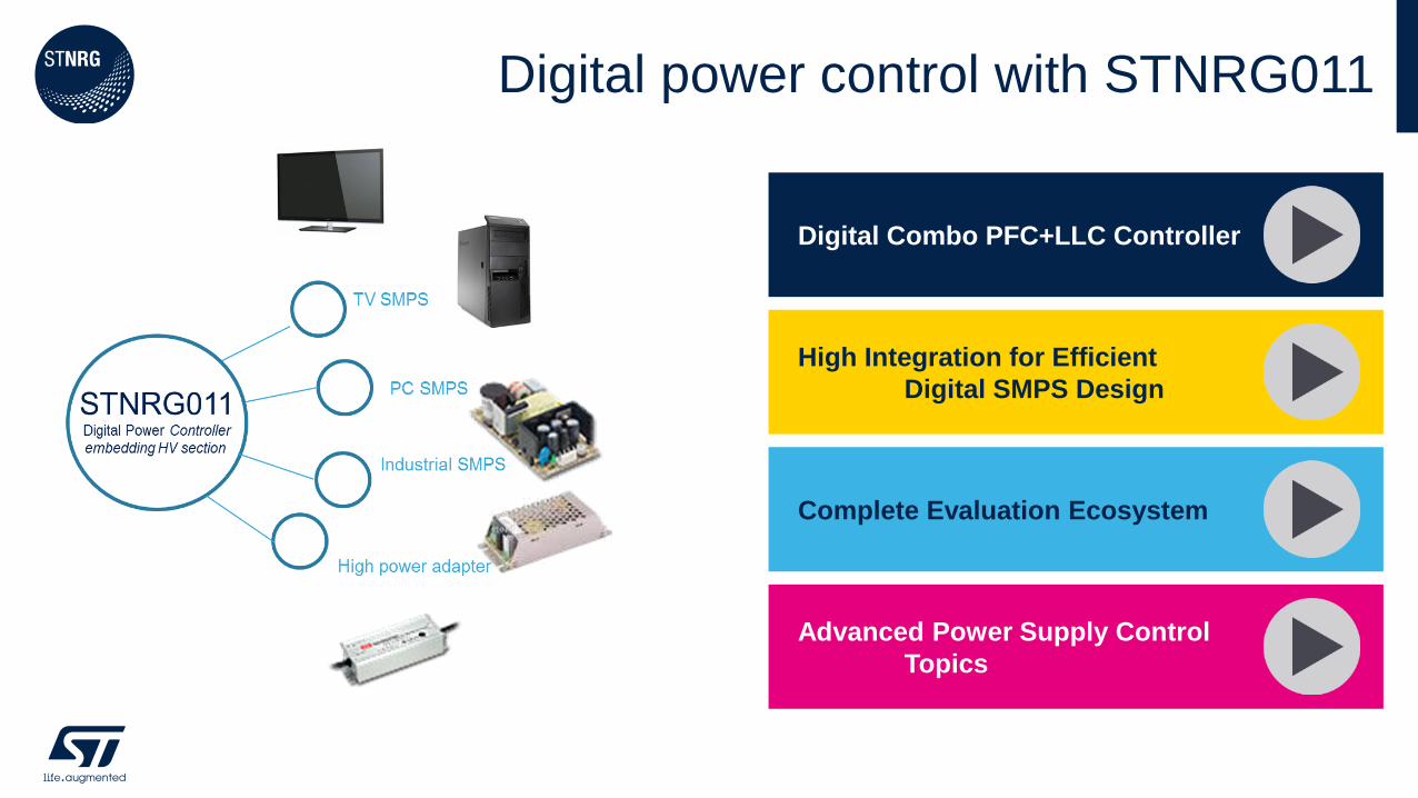
Digital combo PFC+LLC controller
STNRG Provides a Complete Offline Digital Controller Solution
• On chip HV Half Bridge and PFC drivers
• Complete set of PFC and LLC protections
• UART interface for monitoring functions and black box recording
Highlights
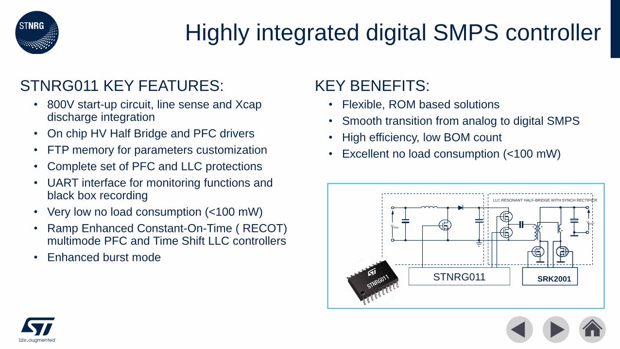
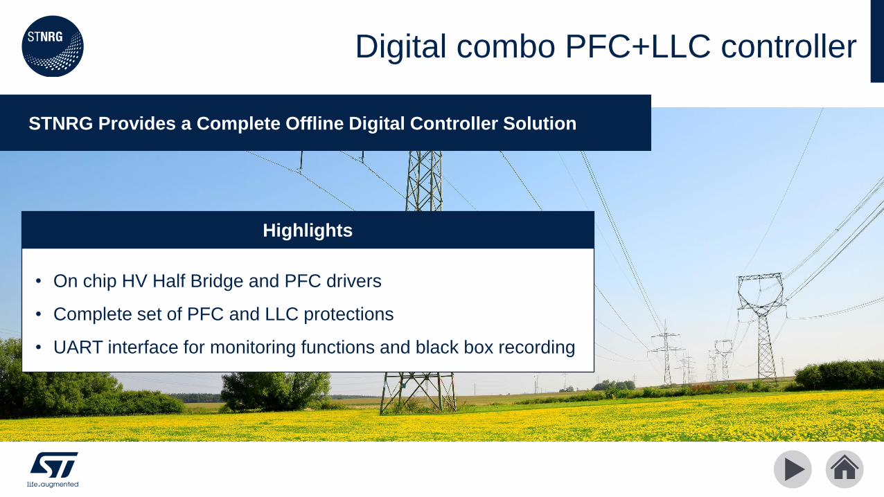
STNRG011 KEY FEATURES:• 800V start-up circuit, line sense and Xcap
discharge integration
• On chip HV Half Bridge and PFC drivers
• FTP memory for parameters customization
• Complete set of PFC and LLC protections
• UART interface for monitoring functions and black box recording
• Very low no load consumption (<100 mW)
• Ramp Enhanced Constant-On-Time ( RECOT) multimode PFC and Time Shift LLC controllers
• Enhanced burst mode
KEY BENEFITS: • Flexible, ROM based solutions
• Smooth transition from analog to digital SMPS
• High efficiency, low BOM count
• Excellent no load consumption (<100 mW)
Highly integrated digital SMPS controller
STNRG011
LLC RESONANT HALF-BRIDGE WITH SYNCH RECTIFIER
SRK2001
VOUTVINac
High integration for efficient digital SMPS design
Integrated Digital Combo Controller Ideal for 90W to 300W SMPSs
• Integrated digital control of HV AC/DC converter
• Low distortion front-end PFC controller
• Efficient LLC converter controller
Highlights
•
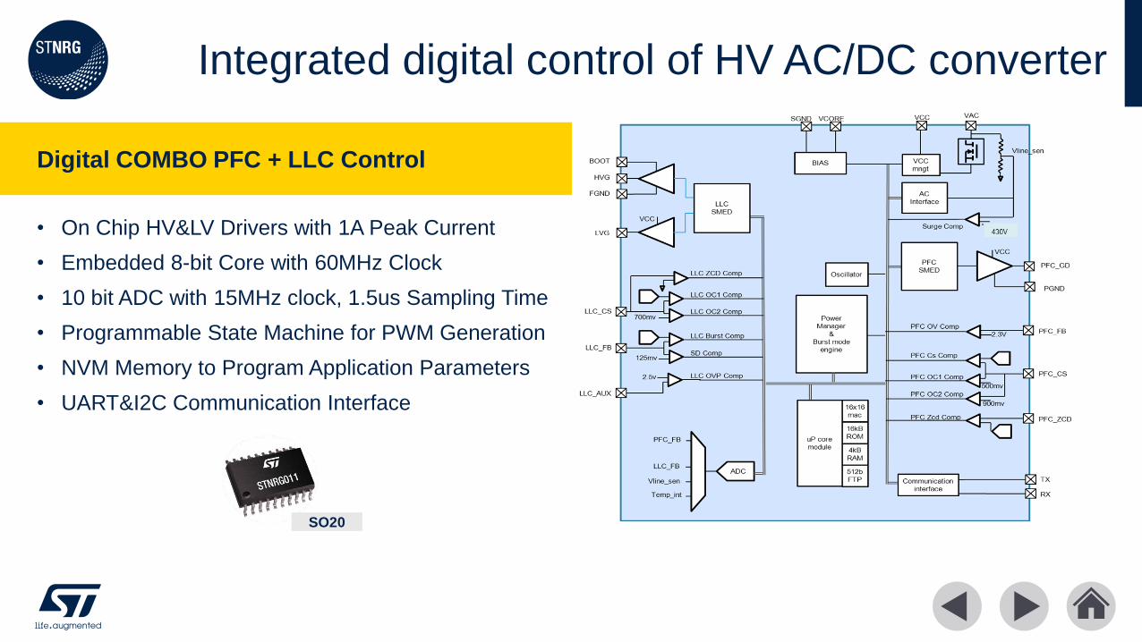
• On Chip HV&LV Drivers with 1A Peak Current
• Embedded 8-bit Core with 60MHz Clock
• 10 bit ADC with 15MHz clock, 1.5us Sampling Time
• Programmable State Machine for PWM Generation
• NVM Memory to Program Application Parameters
• UART&I2C Communication Interface
Integrated digital control of HV AC/DC converter
SO20
Digital COMBO PFC + LLC Control
Power Factor Correction Controller
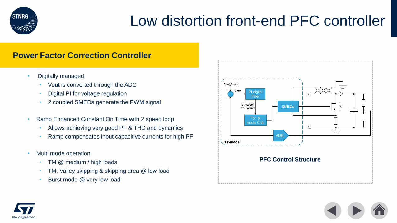
Low distortion front-end PFC controller
• Digitally managed
• Vout is converted through the ADC
• Digital PI for voltage regulation
• 2 coupled SMEDs generate the PWM signal
• Ramp Enhanced Constant On Time with 2 speed loop
• Allows achieving very good PF & THD and dynamics
• Ramp compensates input capacitive currents for high PF
• Multi mode operation
• TM @ medium / high loads
• TM, Valley skipping & skipping area @ low load
• Burst mode @ very low load
PFC Control Structure

Efficient LLC converter controller
• LLC Control managed in Mixed Mode
• Compensation done on secondary side
• ADC samples opto feedback
• 2 coupled SMEDs generate the PWM signal
• The internal core calculates the Time Shift
• Time Shift control
• Improved dynamic performance
• Easy compensation
• Great input voltage ripple rejection (> 50dB)
• Advanced features & protections
• Safe start
• Anti Capacitive Protection
• Over Current management
• Burst Mode Operation driven by LLC
LLC Control Structure
…
Resonant Controller
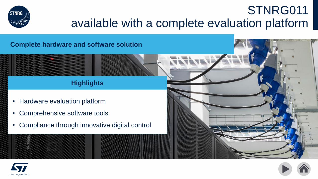
STNRG011 available with a complete evaluation platform
Complete hardware and software solution
• Hardware evaluation platform
• Comprehensive software tools
• Compliance through innovative digital control
Highlights
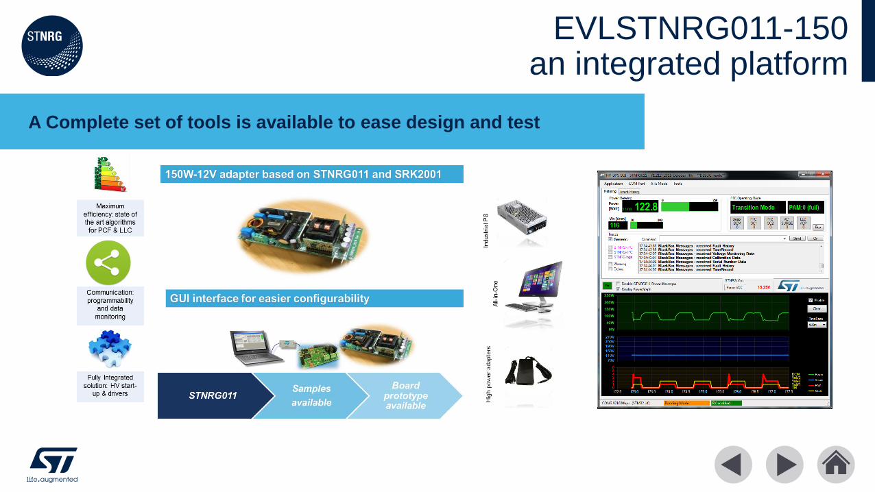
EVLSTNRG011-150an integrated platform
A Complete set of tools is available to ease design and test
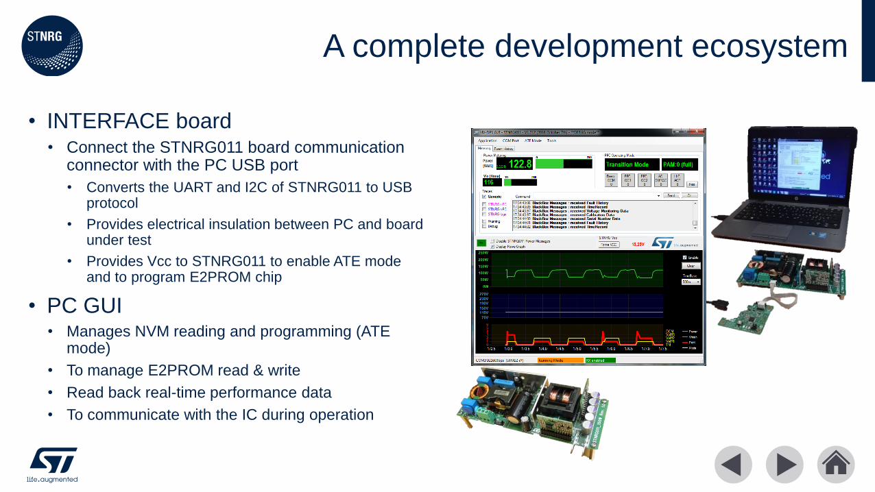
• INTERFACE board • Connect the STNRG011 board communication
connector with the PC USB port
• Converts the UART and I2C of STNRG011 to USB protocol
• Provides electrical insulation between PC and board under test
• Provides Vcc to STNRG011 to enable ATE mode and to program E2PROM chip
• PC GUI• Manages NVM reading and programming (ATE
mode)
• To manage E2PROM read & write
• Read back real-time performance data
• To communicate with the IC during operation
A complete development ecosystem

• PROTECTIONS• Protections behavior (latch / auto restart)
• Protections levels & timings
• COMPARATORS filtering & hysteresis
• PFC• PFC soft start
• PFC loop compensation
• PFC light load behavior
• PFC RECOT parameters (on the fly THD adjustment)
• PFC maximum frequency
• PFC nominal, minimum (UVP) and maximum (OVP) output voltages
• LLC• LLC dead-time
• LLC safe start & soft start parameters
• BURST mode operation• in/out thresholds
• Burst pulses definition
Adjust parameters with digital control
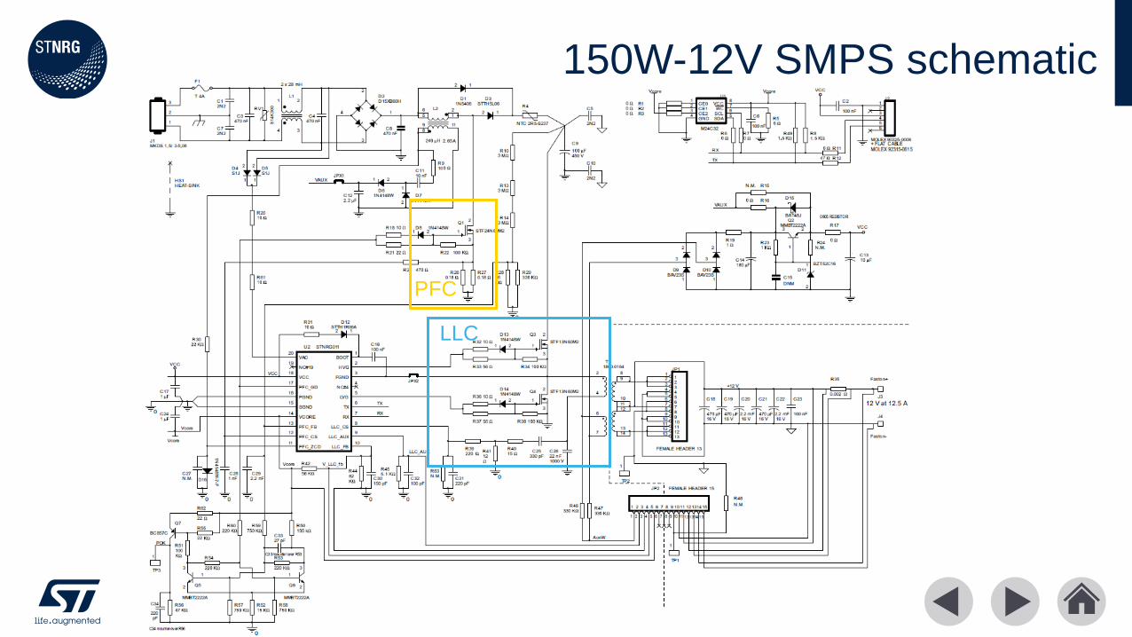
150W-12V SMPS schematic
PFC
LLC

150W platform meets global efficiency standardsEu Coc 5 EPS Tier 2 Limits Result
115Vac
Result
230Vac
Status
4 points avg > 0.89 0.900 0.913 Pass
Eff @ 10% > 0.79 0.836 0.859 Pass
No load < 0.15 W 0.07 0.0934 Pass
Energy star 6.0 for
computer
Limits Result
115Vac
Result
230Vac
Status
Eff @ 20% > 0.82 0.857 0.866 Pass
Eff @ 50% > 0.85 0.902 0.911 Pass
Eff @ 100% > 0.82 0.914 0.929 Pass
PF @ 100% > 0.9 0.994 0.982 Pass
DOE – EISA 2007
(from 2016)
Limits Result
115Vac
Result
230Vac
Status
4 points avg > 0.88 0.900 0.913 Pass
No load < 0.15 W 0.07 0.0934 Pass
ErP Lot 7 Limits Result
115Vac
Result
230Vac
Status
4 points avg > 0.87 0.900 0.913 Pass
No load < 0.5 W 0.07 0.0934 Pass

Advanced digital control topics
High efficiency through high performance control algorithms
• High level system architecture
• Power factor correction details
• LLC converter technical details
Highlights

STNRG011 architecture and pinout
BOOT
HVG
FGND
VAC
n.c.
n.c.
Vcc
PFC_GD
PGNDLVG
SGND
VCORE
PFC_FB
PFC_CS
PFC_ZCD
RX
TX
LLC_CS
LLC_AUX
LLC_FB
Power Section
Signal Section
SO20
TS LLC RESONANT HALF-BRIDGE
WITH SYNCH RECTIFIER
SRK2001
VOUTVINac
MULTIMODE reCOT TM PFC
STNRG011
•
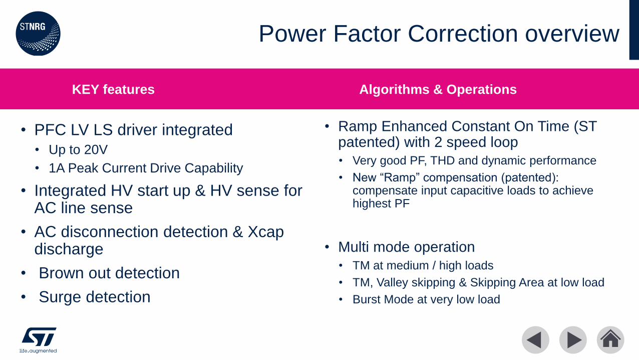
• PFC LV LS driver integrated
• Up to 20V
• 1A Peak Current Drive Capability
• Integrated HV start up & HV sense for AC line sense
• AC disconnection detection & Xcapdischarge
• Brown out detection
• Surge detection
•
• Ramp Enhanced Constant On Time (ST patented) with 2 speed loop
• Very good PF, THD and dynamic performance
• New “Ramp” compensation (patented): compensate input capacitive loads to achieve highest PF
• Multi mode operation
• TM at medium / high loads
• TM, Valley skipping & Skipping Area at low load
• Burst Mode at very low load
Power Factor Correction overview
KEY features Algorithms & Operations
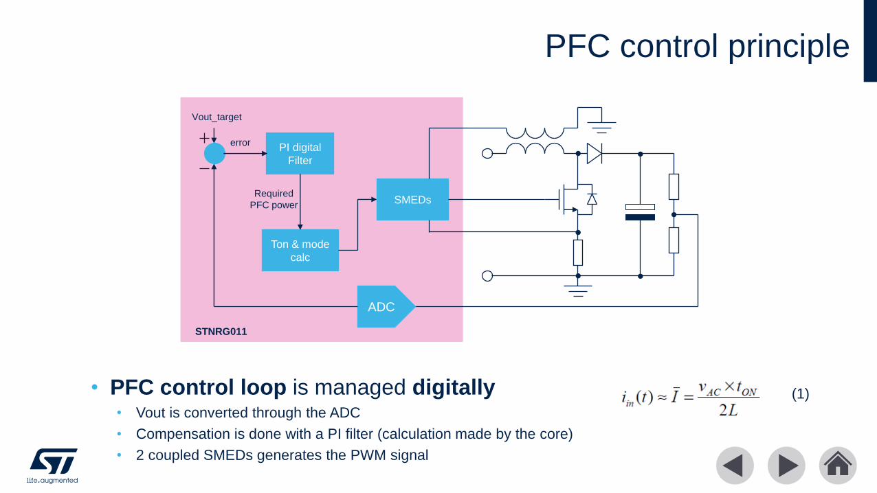
PFC control principle
• PFC control loop is managed digitally• Vout is converted through the ADC
• Compensation is done with a PI filter (calculation made by the core)
• 2 coupled SMEDs generates the PWM signal
PI digital
Filter
Vout_target
error
ADC
SMEDs
Ton & mode
calc
Required
PFC power
STNRG011
(1)
Power Factor Correction details: eCOT
TSW
VGS
VDS
TON
IL
ITH
Ineg = (Vo − Vac) ∙Coss
L
Iin = Vinpk ∙ sin θ ∙TON
2L+ Vinpk ∙ sin θ
Coss
L− Vo
Coss
L
Iin ≈ Vinpk ∙ sin θ ∙TON2 ∙ L
− Ineg + ITH
Iin ≈ Vinpk ∙ sin θ ∙TON2 ∙ L
− Ineg + Vinpk ∙ sin θ ∙Coss
L
𝐈𝐢𝐧 ≈ 𝐊 ∙ 𝐕𝐢𝐧𝐩𝐤 ∙ 𝐬𝐢𝐧𝛉
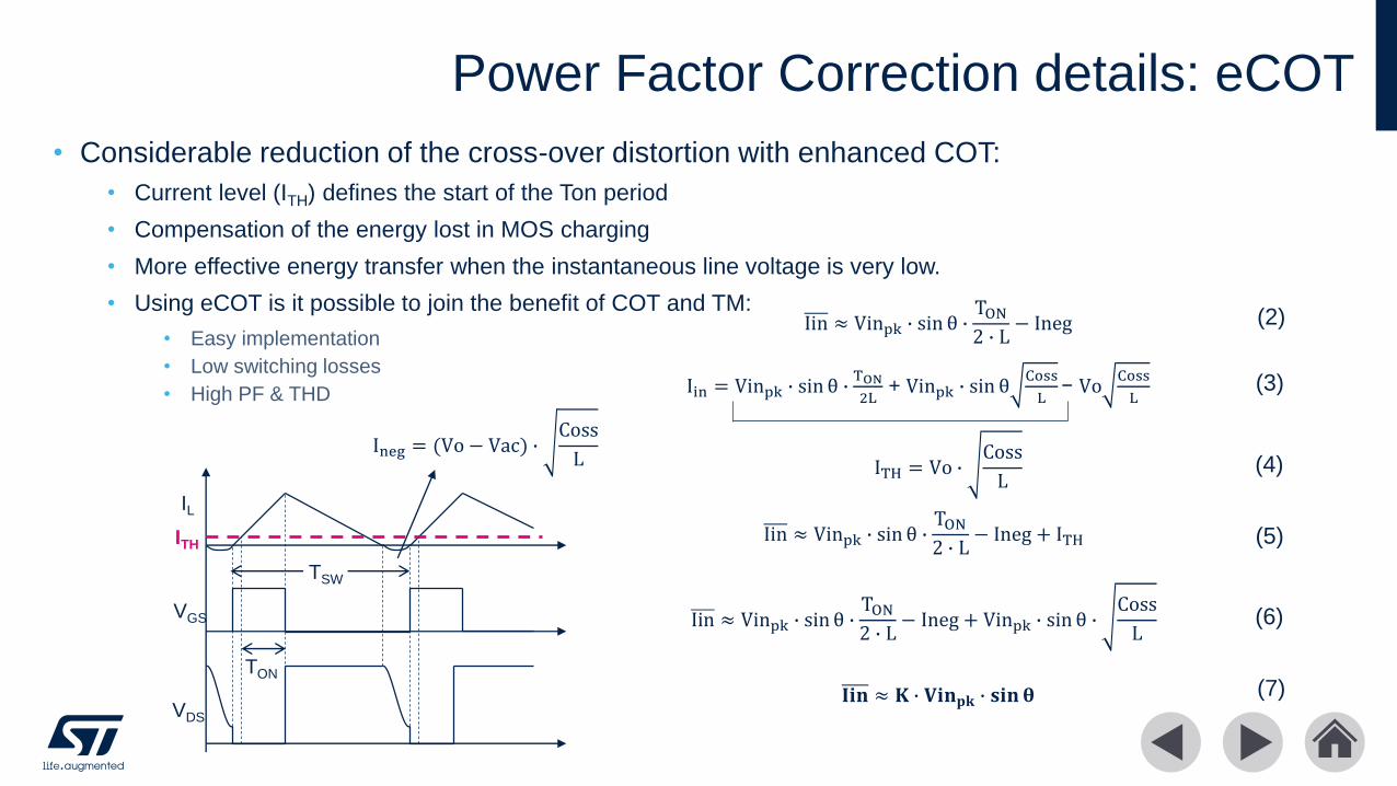
• Considerable reduction of the cross-over distortion with enhanced COT:
• Current level (ITH) defines the start of the Ton period
• Compensation of the energy lost in MOS charging
• More effective energy transfer when the instantaneous line voltage is very low.
• Using eCOT is it possible to join the benefit of COT and TM:
• Easy implementation
• Low switching losses
• High PF & THD
Iin ≈ Vinpk ∙ sin θ ∙TON2 ∙ L
− Ineg (2)
(3)
(4)
(5)
(6)
ITH = Vo ∙Coss
L
(7)
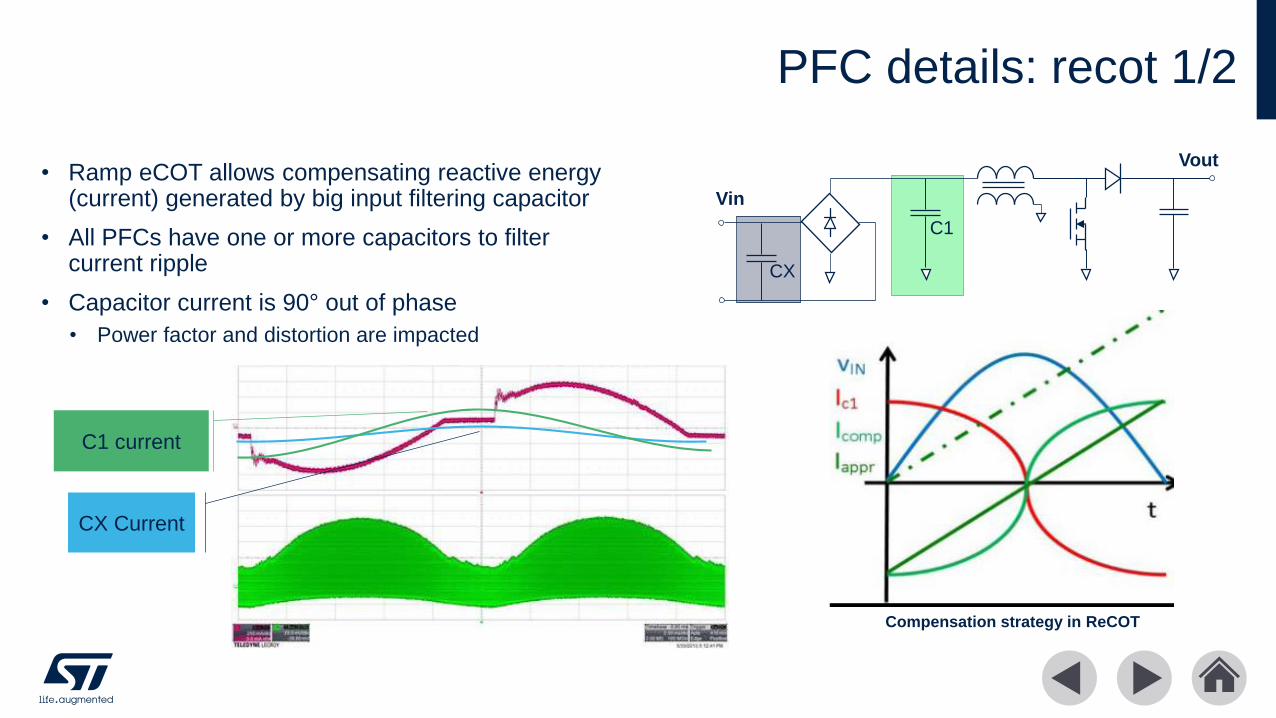
• Ramp eCOT allows compensating reactive energy (current) generated by big input filtering capacitor
• All PFCs have one or more capacitors to filter current ripple
• Capacitor current is 90° out of phase
• Power factor and distortion are impacted
PFC details: recot 1/2
CX Current
C1 current
C1
CX
Vout
Vin
Compensation strategy in ReCOT
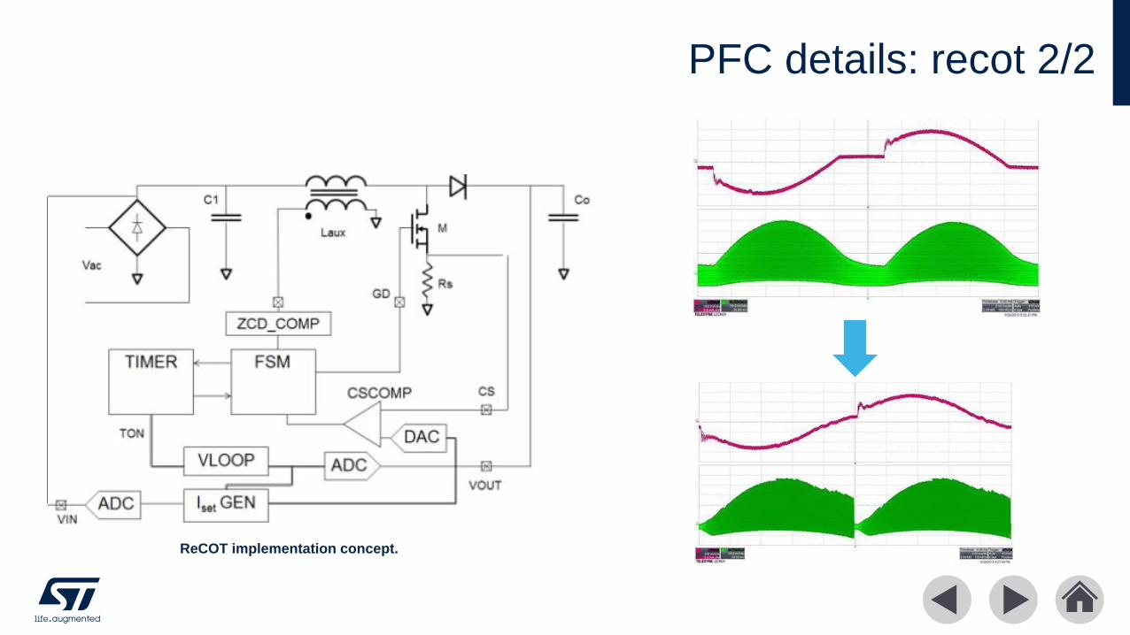
PFC details: recot 2/2
ReCOT implementation concept.
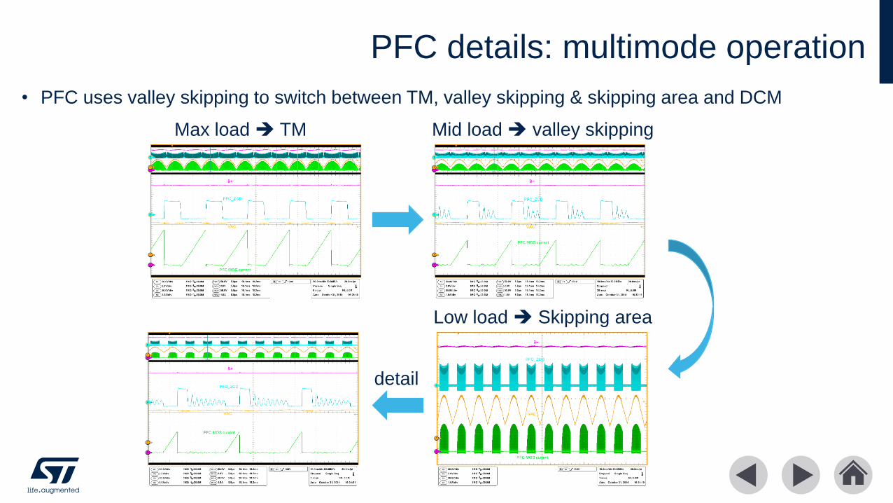
PFC details: multimode operation
• PFC uses valley skipping to switch between TM, valley skipping & skipping area and DCM
Max load ➔ TM Mid load ➔ valley skipping
Low load ➔ Skipping area
detail
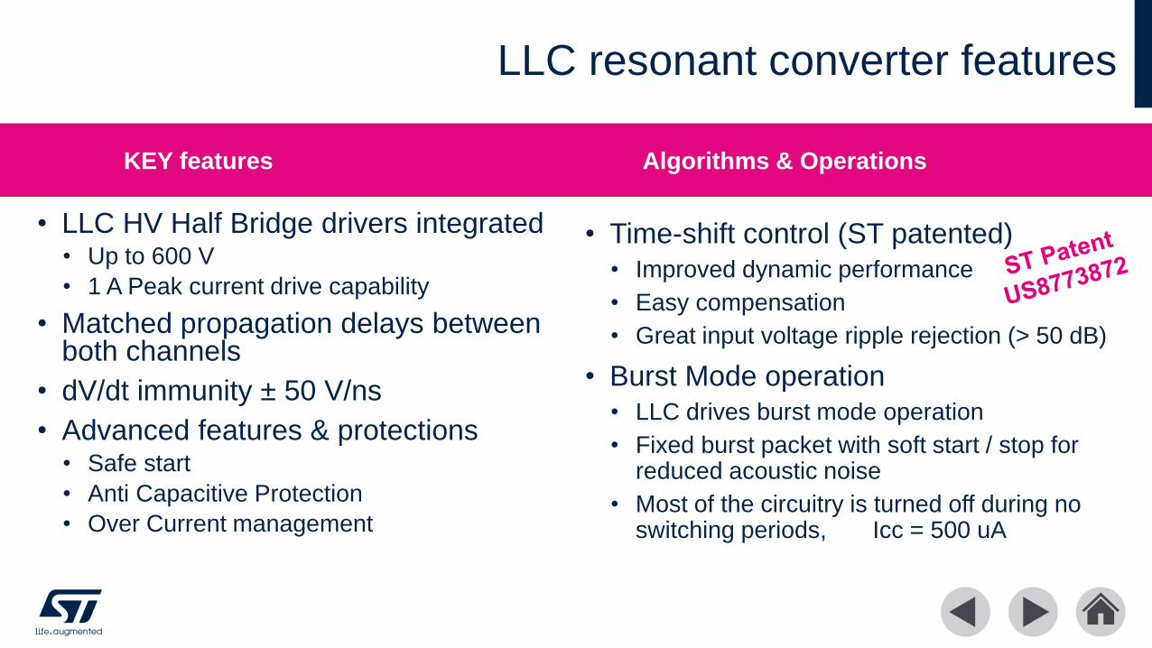
•
• LLC HV Half Bridge drivers integrated• Up to 600 V
• 1 A Peak current drive capability
• Matched propagation delays between both channels
• dV/dt immunity ± 50 V/ns
• Advanced features & protections• Safe start
• Anti Capacitive Protection
• Over Current management
•
• Time-shift control (ST patented)
• Improved dynamic performance
• Easy compensation
• Great input voltage ripple rejection (> 50 dB)
• Burst Mode operation
• LLC drives burst mode operation
• Fixed burst packet with soft start / stop for reduced acoustic noise
• Most of the circuitry is turned off during no switching periods, Icc = 500 uA
LLC resonant converter features
KEY features Algorithms & Operations
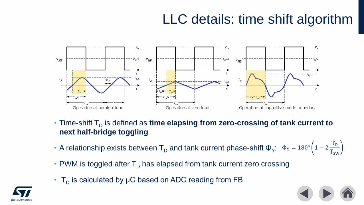
LLC details: time shift algorithm
• Time-shift TD is defined as time elapsing from zero-crossing of tank current to
next half-bridge toggling
• A relationship exists between TD and tank current phase-shift ΦY:
• PWM is toggled after TD has elapsed from tank current zero crossing
• TD is calculated by μC based on ADC reading from FB
ΦY = 180° 1 − 2TDTSW
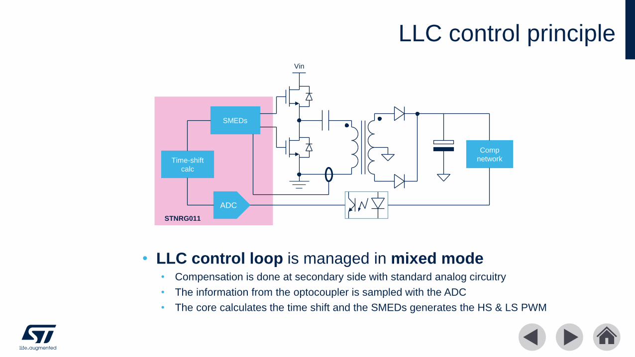
LLC control principle
• LLC control loop is managed in mixed mode• Compensation is done at secondary side with standard analog circuitry
• The information from the optocoupler is sampled with the ADC
• The core calculates the time shift and the SMEDs generates the HS & LS PWM
Vin
ADC
Time-shift
calc
SMEDs
Comp
network
STNRG011
• TSC makes LLC resonant converter dynamics very close to that of a first-order system
• Frequency compensation is much easier
• Response to perturbations is overdamped
• TSC improves load transient response
• Overshoots and undershoots are nearly halved
• Settling time is reduced 3-4 times
• TSC improves input ripple rejection
• 100 Hz gain can be increased considerably
• Rejection ratio increases by more than 15 dB
• TSC prevents hard switching at start-up
• Converter reliability is improved
• Moreover STNRG011 implements the safe start: before the soft start the LVG is turned on for about 10 us order to discharge the resonant capacitor
LLC details: time shift benefits vs DFC

LLC operationSafe start Full load start-up
Full load steady state Min load steady state
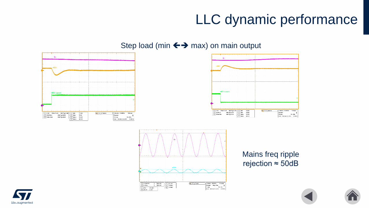
LLC dynamic performance
Mains freq ripple
rejection ≈ 50dB
Step load (min ➔ max) on main output