Embed Size (px)
Citation preview
Derby City Express Louisville, KY 2008
Digital Command Control Design and Operational Considerations
Digital Command Control
Design & Operational Considerations for
Derby City Express NTRAK Layout
Final June 1, 2008
by John M. Wallis
Digital Master Derby City Express
Questions, comments, corrections and suggestions should be addressed to the author at [email protected]
Copyright © 2008, by John M. Wallis

Page 2 Derby City Express DCC Design Specification
Special note: This document is formatted for printing on both sides of the paper (duplex printing), such that main sections will always start with an odd numbered page. If printing on single side only then there will be a number of blank sheets in the document.
Derby City Express DCC Design Specification Page 3
Table of Contents
1. Introduction .........................................................................................................................................9
2. Layout Size and Complexity................................................................................................................9
3. Digital Staff........................................................................................................................................10 3.1 Digital Master ...........................................................................................................................11 3.2 Assistant Digital Masters ..........................................................................................................11 3.3 Device ID Manager...................................................................................................................11
3.3.1 LocoNet Management ..................................................................................................11 3.3.2 Device ID Assignment ..................................................................................................11
3.4 Programming Manager.............................................................................................................11 3.5 Loop/Setup/Teardown..............................................................................................................11 3.6 Loop DCC Coordinators ...........................................................................................................12 3.7 Technical Support ....................................................................................................................12 3.8 Digital Staff Meeting .................................................................................................................12
4. DCC System, Architecture and Configuration...................................................................................12 4.1 Red Line Route DCC System...................................................................................................12 4.2 Architecture ..............................................................................................................................14 4.3 Command Node Architecture and Configuration......................................................................15
4.3.1 Active Command Station ..............................................................................................15 4.3.2 Backup Command Station............................................................................................16 4.3.3 Programming Command Station ..................................................................................16
4.4 Junction Node ..........................................................................................................................16 4.5 Loop Configuration...................................................................................................................16
4.5.1 Loop BoosterNet...........................................................................................................17 4.5.2 Loop ThrottleNet...........................................................................................................17
5. Boosters, Power Management and Grounding .................................................................................18 5.1 Boosters ...................................................................................................................................18 5.2 Power Management .................................................................................................................19 5.3 Booster Grounding ...................................................................................................................20
5.3.1 Grounding Guidelines...................................................................................................20 5.3.2 “Grounding” for Derby City Express .............................................................................21
6. Throttles ............................................................................................................................................22
7. Programming.....................................................................................................................................22 7.1 Address Assignments...............................................................................................................22
7.1.1 Four-Digit Addresses .....................................................................................................23 7.1.2 Two-Digit Addresses......................................................................................................23
7.2 Programming Stations..............................................................................................................23 7.3 Consisting ................................................................................................................................23 7.4 Operations Mode Programming ...............................................................................................24 7.5 Throttle Emergency Stop..........................................................................................................24 7.6 Unique Throttle Identification....................................................................................................24
8. Track Power Distribution ...................................................................................................................24 8.1 Centralized Power Distribution .................................................................................................25 8.2 Distributed Power Distribution ..................................................................................................25 8.3 Track Bus Filters and Terminators ...........................................................................................25
Page 4 Derby City Express DCC Design Specification
9. LocoNet.............................................................................................................................................25
10. Throttle LocoNet Network and Universal Panels ..............................................................................27
11. Booster LocoNet Network and Grounding ........................................................................................29
12. Radio Receivers................................................................................................................................30 12.1 Digitrax UR91 Radio Receivers ...............................................................................................30 12.2 Digitrax UR91 Radio Capacity .................................................................................................30 12.3 Digitrax UR91 Connections......................................................................................................30 12.4 Interference from Other Systems .............................................................................................30
13. Other DCC Devices ..........................................................................................................................31 13.1 Device Classes ........................................................................................................................31
13.1.1 NMRA Compliant Stationary Decoders.......................................................................31 13.1.2 Non-NMRA Compliant Accessory Decoders ..............................................................31
13.2 Potential Problems ...................................................................................................................31 13.3 Possible Solutions....................................................................................................................31
13.3.1 Appropriate Signals May Not Always Be Available.....................................................31 13.3.1.1 Wiring Accessory Decoders if No Signals is Available..............................32 13.3.1.2 Obtaining an Appropriate Signal ...............................................................32
13.3.2 More Than One Module Has the Same Address for a Stationary Decoder ................32 13.3.3 Operators Unfamiliar with Accessory Decoder Operation ..........................................33
13.4 Preparing for Derby City Express.............................................................................................33 13.5 Derby City Express Setup and Operation ................................................................................33 13.6 Acceptable Devices..................................................................................................................34
14. Setup and Test..................................................................................................................................34 14.1 Setup........................................................................................................................................35
14.1.1 Setup Proceedings .......................................................................................................35 14.1.2 Module Inspection ........................................................................................................35 14.1.3 Section Isolation ...........................................................................................................35 14.1.4 Device ID Management................................................................................................36
14.1.4.1 LocoNet Management..................................................................................36 14.1.4.2 Device ID Management................................................................................36
14.2 Command Station Complex Setup...........................................................................................37 14.3 Manufacturing and Testing LocoNet Cables ............................................................................37 14.4 ThrottleNet Setup .....................................................................................................................37 14.5 BoosterNet Setup.....................................................................................................................37 14.6 Testing the DCC System..........................................................................................................38
15. Operations ........................................................................................................................................38 15.1 Power-Up Sequence ................................................................................................................38 15.2 Layout Operations....................................................................................................................38
15.2.1 Track and Wheel Cleaning ...........................................................................................38 15.2.2 Command Station.........................................................................................................38 15.2.3 Radio Throttles .............................................................................................................38 15.2.4 LocoNet Bus Speed .....................................................................................................39
15.3 System Reset...........................................................................................................................39 15.4 System Shut Down...................................................................................................................39
Derby City Express DCC Design Specification Page 5
16. Monitoring, Measuring and Troubleshooting.....................................................................................39 16.1 System Monitoring....................................................................................................................39
16.1.1 Digitrax LocoNet Checker ...........................................................................................40 16.1.2 JMRI LocoNet Tools ...................................................................................................40 16.1.3 Monitor Computer .......................................................................................................40
16.2 Measuring and Monitoring Voltage and Current.......................................................................40 16.3 Other Test Equipment ..............................................................................................................40 16.4 Troubleshooting .......................................................................................................................41
17. Tear Down.........................................................................................................................................41
18. Equipment and Material List..............................................................................................................41 18.1 Equipment ................................................................................................................................42
18.1.1 Command Station.........................................................................................................42 18.1.2 Boosters .......................................................................................................................41 18.1.3 Digitrax DCC Devices...................................................................................................42 18.1.4 Other Equipment ..........................................................................................................42
18.2 Material ....................................................................................................................................42 18.3 Miscellaneous Tools.................................................................................................................43
19. References........................................................................................................................................43
Appendix A NTRAK Junction Modules — A Step-By-Step Approach ..................................................45 A.1 Overview ..................................................................................................................45 A.2 Step 1 — Outside Corner.........................................................................................45 A.3 Step 2 — Add Spine Red Track Connection............................................................46 A.4 Step 3 — Add Spine Blue Track Connection ...........................................................46 A.5 Step 4 — Add Spine Yellow Track Connection........................................................47 A.6 Configuration Switches ............................................................................................48
A.6.1 Alternate 4PDT Configuration Switches .......................................................49 A.7 Powering the Spine..................................................................................................49 A.8 Feed from the Junction ............................................................................................50 A.9 Mid-Spine Feed........................................................................................................50
Appendix B: Summary Throttle Operating Instructions .........................................................................51
B.1 DTxxx Throttles ........................................................................................................51 B.1.1 Throttle Knob Movements ............................................................................51 B.1.2 Throttle Orientation.......................................................................................51 B.1.3 Display Power Down ....................................................................................51
B.2 DTxxx Throttle Operations .......................................................................................52 B.2.1 Select Locomotive to Drive...........................................................................52 B.2.2 Controlling Lights and Functions ..................................................................52 B.2.3 Locomotive Speed and Direction Control.....................................................52 B.2.4 Dispatching/Releasing an Address from LocoNet........................................53 B.2.5 Stealing a Locomotive/Slot Following...........................................................53 B.2.6 Status Editing a Decoder..............................................................................53 B.2.7 Setting Throttle Options................................................................................53
B.3 DTxxx Throttle Consisting ........................................................................................54 B.3.1 Basic Consisting...........................................................................................54 B.3.2 Advanced (Decoder Assisted) Consisting ....................................................54
B.4 Programming Decoders ...........................................................................................54 B.5 UT4R Throttle...........................................................................................................55 B.6 Throttle Problems and Maintenance ........................................................................55
B.6.1 Battery ..........................................................................................................55
Page 6 Derby City Express DCC Design Specification
B.6.2 No Radio Operation .....................................................................................56 B.6.3 Loose Throttle Knobs ...................................................................................56 B.6.4 RJ12 Plug.....................................................................................................56
Appendix C Decoder Programming and Consisting.............................................................................57 C.1 Hints for Successful Programming...........................................................................57 C.2 Sound in Programmable Sound Decoders ..............................................................57 C.3 JMRI DecoderPro ....................................................................................................57 C.4 Decoder-Assisted Consisting...................................................................................59 C.5 UniVersal Consisting................................................................................................61 C.6 Releasing/Dispatching Locomotives from the Throttle.............................................61 C.7 Throttle Emergency Stop Setting .............................................................................62
Appendix D Digitrax LocoNet Repeater (LNRP) ..................................................................................63 D.1 Introduction ..............................................................................................................63 D.2 General LNRP Connection Scheme ........................................................................64 D.3 Derby City Express LNRP Connection Scheme ......................................................64 D.4 LNRP Fault Codes ...................................................................................................65
Appendix E Module Inspection.............................................................................................................67 E.1 Pre-Certification Inspection......................................................................................67
E.1.1 Track Inspection ............................................................................................67 E.1.2 Electrical Inspection.......................................................................................68
E.2 On-Site Inspection ...................................................................................................69
Appendix F LocoNet Management ......................................................................................................71 Appendix G Digitrax Sensor and Switch Address Ranges ...................................................................73 Appendix H Command Station Configuration and Operation...............................................................77
H.1 Total System Reset..................................................................................................77 H.2 Command Station Parameter Configuration ............................................................77 H.3 DCS100 or DCS200 Command Stations Used as Booster Only .............................79 H.4 DCS50 Command Station Used as Booster Only....................................................79 H.5 DB100 Command Station Used as Booster Only ....................................................79 H.6 DB150 Command Station Used as Booster Only ....................................................80
Appendix I Manufacturing and Testing LocoNet Cables.....................................................................81 I.1 Manufacturing LocoNet Cables................................................................................81 I.2 Testing a LocoNet Cable .........................................................................................82
I.2.1 Testing a LocoNet Cable Using the Digitrax LT-1 Tester ..............................82 I.2.2 Warning re Use of LT-1 Tester During Layout Operations ............................83
Appendix J Installing and Testing LocoNet Wiring ..............................................................................85
J.1 LocoNet Wiring at the Command Node ...................................................................85 J.2 Extending the Backbone LocoNet Along the Layout Spine .....................................86 J.3 Extending ThrottleNet Around the Layout Loops .....................................................87 J.4 Extending BoosterNet Around the Layout Loops.....................................................88
Appendix K Booster Phasing and Grounding, Track Polarity and Coin Test .......................................91 K.1 Booster Phasing — Input .........................................................................................91 K.2 Booster Phasing — Output ......................................................................................91 K.3 Checking Track Polarity ...........................................................................................92
Derby City Express DCC Design Specification Page 7
K.4 The Coin Test...........................................................................................................92 K.5 Booster Grounding...................................................................................................92
Appendix L Power Up, System Reset and Shut Down Sequences .....................................................93 L.1 Power Up Sequence ................................................................................................93
L.1.1 Command Station ..........................................................................................93 L.1.2 Boosters.........................................................................................................93
L.2 System Reset...........................................................................................................93 L.2.1 OPSW #36 Reset ..........................................................................................93 L.2.2 OPSW #39 Reset ..........................................................................................94
L.3 Shut Down Process..................................................................................................94
Appendix M Track and Wheel Cleaning................................................................................................95 M.1 Cleaning Track.........................................................................................................95 M.2 Cleaning Peco Turnouts...........................................................................................96 M.3 Cleaning Wheels ......................................................................................................96
Appendix N System Monitoring, Configuration and Measuring ............................................................97 N.1 Command Station Slot Monitoring ...........................................................................97 N.2 Device Configuration................................................................................................98
N.2.1 Command Station Configuration....................................................................98 N.2.2 PM42 Power Manager Configuration.............................................................98
N.3 LocoNet Monitor.....................................................................................................100 N.4 Voltage and Current Measurements ......................................................................100
N.4.1 Measuring Voltage Drop and Loss ..............................................................101 N.4.2 Monitoring Voltage and Current...................................................................102
Appendix O Troubleshooting ..............................................................................................................103 O.1 Introduction ............................................................................................................103 O.2 Tools Required.......................................................................................................103 O.3 Troubleshooting the Layout....................................................................................103 O.4 Troubleshooting Command Station/Booster Problems ..........................................104
O.4.1 Command Station Audible Sounds ............................................................104 O.4.2 Nothing is Responding ...............................................................................104
O.4.2.1 No LEDs Lit on Front Panel of Command Station/Booster..........104 O.4.2.2 Some LEDs Lit on Front Panel of Command Station/Booster .....105
O.4.3 No Power or Intermittent Operation............................................................105 O.4.4 Troubleshooting Command Station/Booster Shutdowns............................105 O.4.5 Layout Wiring Issues ..................................................................................105
O.5 Replacing a Broken RJ12 Plug ..............................................................................105 O.6 Troubleshooting LocoNet Problems.......................................................................106 O.7 Troubleshooting UP3 or UP5 Universal Panels .....................................................107 O.8 Troubleshooting Lost Control of Trains ..................................................................108
O.8.1 Analog Address 00 is Active.......................................................................108 O.8.2 Locomotive Address Purging .....................................................................108 O.8.3 Clear Command Station Locomotive and Consist Information...................108 O.8.4 Throttle Power ............................................................................................109 O.8.5 Throttle Settings .........................................................................................109 O.8.6 Throttle Battery...........................................................................................110 O.8.7 UR91 Radio Receivers...............................................................................110 O.8.8 Radio Deadspots........................................................................................111 O.8.9 Command Station Reset ............................................................................111
O.9 Short Circuits at Insulated Rail Frogs.....................................................................111

Page 8 Derby City Express DCC Design Specification
O.10 Troubleshooting Automatic Reverse Problems......................................................112 O.11 Troubleshooting Advanced Consist Related Problems..........................................113
O.11.1 Single Locomotive Does Not Run at its Address .......................................113 O.11.2 Advanced Consist Does Not Run...............................................................113 O.11.3 Headlights/Functions Don’t Work on Lead Locomotive..............................113
O.12 Troubleshooting Mobile Decoder Problems...........................................................113
Derby City Express DCC Design Specification Page 9
Design & Operational Considerations for
Derby City Express NTRAK Layout 1. Introduction The Derby City Express 2008 National NTRAK Convention will feature an NTRAK layout with more than 700 modules, the largest NTRAK layout ever, featuring a Red Line Route© more than 100 scale miles long. The intent of this document is to specify in detail the DCC system for Derby City Express such that railroad operations are successful, continuous and reliable throughout the Convention. A conservative approach is being taken to ensure a “more than enough” design. The premise is that over-design is preferred to under-design. The entire Red Line Route© (RLR) will be DCC-powered. This specification includes the ability for Yellow and/or Blue and/or Green tracks within the various loops of the layout to be either DCC- or DC-powered, except for those loops which have internal yards used for staging trains on the Red Line Route, which must of necessity be part of the main DCC system. 2. Layout Size and Complexity A major factor in DCC design is the layout size and complexity, with clearly a larger and/or more complex layout requiring a much higher level of DCC design. The Derby City Express layout will be both very large and very complex. Failure to take complexity into account can result in operational difficulties that may be very hard to troubleshoot and correct. The presence of the following items adds to the complexity of layouts of all sizes, especially the Derby City Express layout: • Junction Modules. These modules are used in layouts to split tracks from one direction to another
usually at right angles. Some trains may travel straight though the module; other trains may curve to a new track at a right angle to their original direction of travel. A pair of Junction Modules is usually configured to create a loop of NTRAK modules off a set of backbone or spine modules. Some junction modules may also include a reversing section.
There are currently no standard wiring plans for Junction Modules. However, the Step-by-Step Approach to NTRAK Junction Modules, as detailed in Appendix A, is highly recommended as a detailed guide for wiring NTRAK Junction Modules.
• Reversing Loops. These modules are used to reverse the direction of a train, and require that
polarity of the rails be reversed for the train to enter or leave the reversing loop. There is a need to ensure both rails are gapped at each end of the reversing loop, and to be sure there are only two entrances to the loop. The tracks at each end of the reversing loop must be powered from the same electrical district.
• Wyes. Another form of reversing loop, except the reversing section is generally short. This may cause problems with trains traversing the reversing part of the wye, especially trains with Kato or other lighted passenger cars, lighted cabooses or track-powered cars with End-of-Train devices. There is a need to ensure both rails are gapped at each end of the reversing loop, and to be sure
Page 10 Derby City Express DCC Design Specification
there are only two entrances to the loop. The tracks at each end of the reversing loop must be powered from the same electrical district.
• Balloon Modules. Yet another form of reversing loop. The polarity of the rails must be reversed for the train to enter or leave the reversing loop. Both rails must be gapped at each end of the reversing section, and the tracks at each end must be powered from the same electrical district.
• Yards. The complex trackwork that can be located in yards needs to be watched closely, especially
any tracks that can be switched between DC and DCC power. A complete wiring diagram and operational notes are recommended to aid those unfamiliar with the features of a particular yard.
• Multiple DCC Tracks with Different DCC Polarity. Some NTRAK layouts use modules for train
travel in both directions (note: this is not bi-directional running). In this case travel in one direction is, say, on the Red track and travel in the reverse direction is, say, on the Blue track (this is typical on modules used in the spine between Junction Modules). When this is the case the DCC track feed to Blue may need to be the reverse polarity of the feed to Red and/or Yellow.
• Private Tracks. The prime concern with Private Tracks is how they are powered and the need to
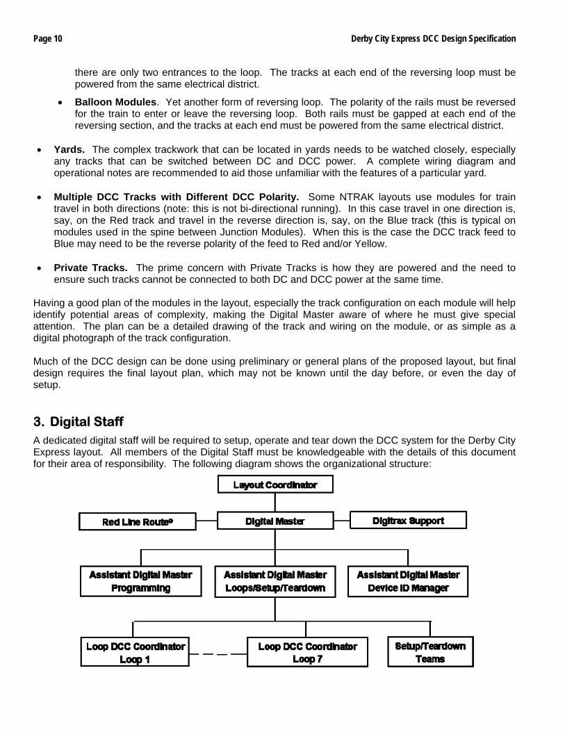
ensure such tracks cannot be connected to both DC and DCC power at the same time. Having a good plan of the modules in the layout, especially the track configuration on each module will help identify potential areas of complexity, making the Digital Master aware of where he must give special attention. The plan can be a detailed drawing of the track and wiring on the module, or as simple as a digital photograph of the track configuration. Much of the DCC design can be done using preliminary or general plans of the proposed layout, but final design requires the final layout plan, which may not be known until the day before, or even the day of setup. 3. Digital Staff A dedicated digital staff will be required to setup, operate and tear down the DCC system for the Derby City Express layout. All members of the Digital Staff must be knowledgeable with the details of this document for their area of responsibility. The following diagram shows the organizational structure:
Derby City Express DCC Design Specification Page 11
The Digital Master and/or one of the three Assistant Digital Masters will be present during all hours the Derby City Express NTRAK layout is operating.
People requirements during setup and teardown will be 18–20 people. During operations 4–6 people will be needed. Job descriptions are: 3.1 Digital Master
The Layout Coordinator will appoint a Digital Master who will be responsible for the design, setup, operation, reliability, monitoring and troubleshooting of the DCC system at the Derby City Express NTRAK layout. The Digital Master will be responsible for appointing Assistant Digital Masters and other digital staff. No changes will be made to the design, implementation or operational aspects of the DCC layout without the agreement of the Digital Master. The Digital Master will be responsible to the overall Layout Coordinator.
3.2 Assistant Digital Masters Three (3) Assistant Digital Masters will be appointed to work with and support the Digital Master so there is always either the Digital Master or an Assistant Digital Master present during all hours the layout is in operation.
3.3 Device ID Manager
One of the Assistant Digital Masters will be assigned the task of Device ID Manager, responsible for ensuring that all DCC devices are assigned a unique address that does not interfere with any other device. This includes the following functions: 3.3.1 LocoNet Management
LocoNet Management is the assigning of LocoNet IDs to the various loops in the NTRAK layout that are not part of the Red Line Route system, and to other layouts at the Convention. This includes assisting the coordinator of each loop or layout in correctly setting the assigned LocoNet ID for that loop/layout, and responsibility for periodically monitoring the various LocoNets to ensure IDs have not changed during the Convention. If any Digitrax dealers at the World’s Greatest Hobby on Tour Show will use radio operation to display their products they must also be assigned a LocoNet ID.
3.3.2 Device ID Assignment Device ID Assignment relates to ensuring that any stationary decoders or other devices that will be used on the layout will have unique addresses or other ID necessary to ensure such devices do not interfere with each other.
3.4 Programming Manager
One of the Assistant Digital Masters will be assigned the task of Programming Manager. The Programming Manager will be responsible for installing, operation and staffing of the programming station(s) that will be set up at the layout.
3.5 Loops/Setup/Teardown
One of the Assistant Digital Masters will be assigned the task of managing the Loop DCC Coordinators and the Setup/Teardown Teams. A minimum of two (2), but preferably four (4) two-person teams will be required for the installation and test of the DCC system (Boosters, Radio Receivers, Universal Panels, LocoNet cables, etc.) on the Red Line Route and in the loops with DCC
Page 12 Derby City Express DCC Design Specification
where the DCC is part of the Red Line Route DCC system. The setup/tear down teams will assist the Loop DCC Coordinators.
3.6 Loop DCC Coordinators Since the Loop DCC Coordinators will likely be familiar with most of the modules in their loop they will have the prime responsibility for the successful installation and testing of DCC in their loop, with assistance from the setup/tear down teams, and in accordance with the rules provided in this document and the locations defined on the layout plan for Boosters, Radio Receivers and other DCC devices, including Universal Panels. This responsibility includes both the Red Line Route and any DCC system serving the other tracks in the loop, whether part of the Red Line Route DCC system or independent. It also includes any DC control system in the loop. For independent and DC systems the Digital Staff will help in the event of problems and to ensure the systems are truly independent, and, if Digitrax, assign a LocoNet ID.
3.7 Technical Support
Support for DCC operations will be provided by Digitrax. In the provision of this support, Digitrax will work with the Digital Master.
3.8 Digital Staff Meeting
There will be an informal meeting of the Digital Staff prior to the start of setup of the layout at a time and location to be advised. The purpose is to meet each other and have a Q&A session. Attendees will also review diagrams showing where all blocks, gaps, Command Stations, Boosters, etc. would be in the layout so these diagrams and others could be given and explained to others during setup, especially other Digital Staff and the clubs responsible for setting up the loops.
4. DCC System, Architecture and Configuration 4.1 Red Line Route DCC System
The DCC system to be used for the Red Line Route and any other loop tracks that will be part of the Red Line Route DCC system at Derby City Express is the Digitrax Digital Command Control system, specifically the Digitrax Super Chief. The track voltage switch on the Command Station and all Boosters will be set to the “N” Scale position (nominal 12 volts), and memory slots will be set to 120. A set of Digitrax manuals for all Digitrax and other DCC equipment in use at Derby City Express will be prepared and located at the Command Station throughout the Convention either in printed form, a CD-ROM or a USB thumb drive. Soft files will be transferred to computers located at the Command Station and Programming Stations all of which will have Adobe Acrobat Reader 8.0 (or equivalent) installed. No components from any other manufacturer’s DCC system will be permitted connection to the layout, except as specified in this document or designated by the Digital Master, and unless LocoNet Certified. A specific exception is given for decoders (both mobile and stationary), throttle panels and power managers from other manufacturers provided they conform to all appropriate specifications. Loops with fully independent DCC tracks (yellow, blue, green) may use any DCC system of their choice as long as there is no interconnection to the main Red Line Route system, and provided the system causes no interference with the Digitrax system. With the addition to the Digitrax DCC System of components such as stationary decoders, block detectors, transponding and signaling the interconnection of components becomes more complex than just LocoNet and track power. The diagram below shows a generic connection matrix of the various Digitrax DCC components. Details will be provided in the appropriate sections of this
Derby City Express DCC Design Specification Page 13
specification, with an extensive discussion in Section 9. The prime issue is ensuring that all such equipment (DS64, SE8c, etc.) is assigned to unique addresses so there is no interference from one area of the layout to another.
Digitrax Modules, Connections and Steps
(Wiring shown is for general illustration only, not intended to be a complete diagram)
Diagram courtesy of Train Buddy Products, ©2003–2008, all rights reserved. Used with permission.
Page 14 Derby City Express DCC Design Specification
Interconnection between most components of the Digitrax system utilizes LocoNet®, a proprietary Digitrax communications network especially designed for this purpose. For many applications a single LocoNet daisy-chained from component-to-component provides the optimum method of interconnection.
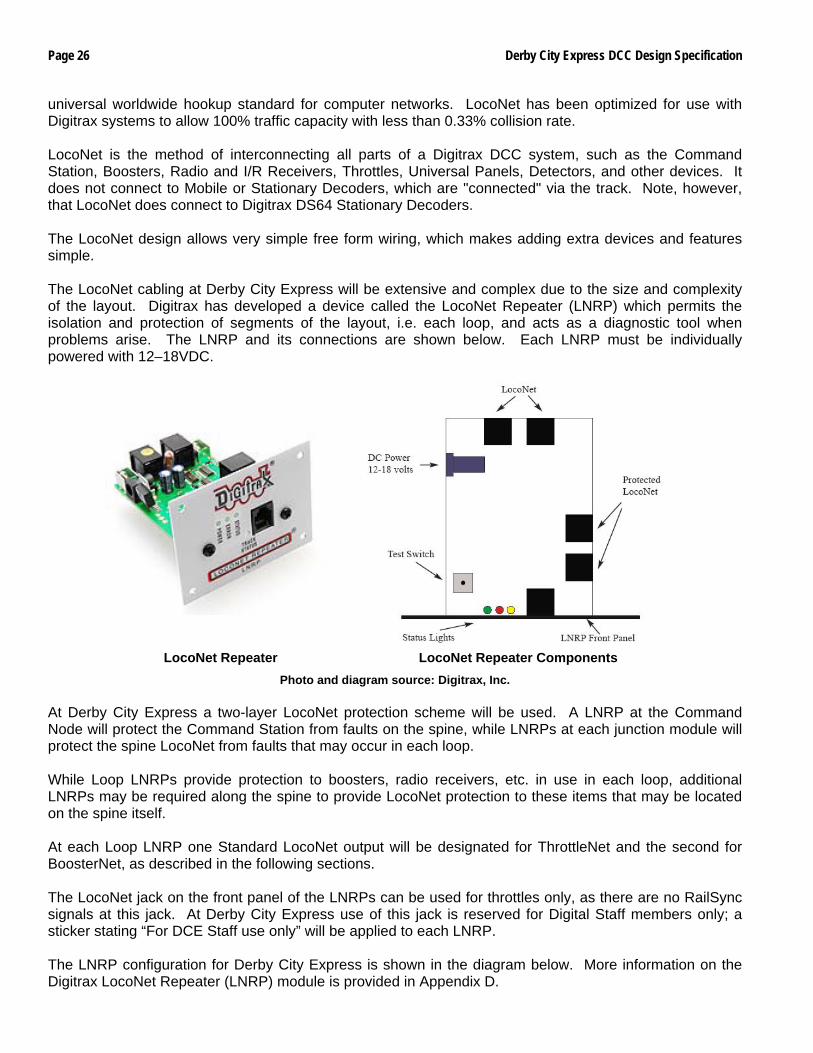
4.2 Architecture
Because of the size of the layout at Derby City Express, the electrically noisy environment of the Convention Center and the prime objective of continuous, reliable running of trains the LocoNet at Derby City Express will be configured to be a rugged and reliable network utilizing the Digitrax LocoNet Repeater (LNRP) Module. This two-tiered protection, as shown in the diagram below, will utilize the LNRP to isolate and protect LocoNet segments, as follows:
• A single “backbone” LocoNet will connect the Command Node to individual Loop Junction nodes.
• Separate ThrottleNet and BoosterNet connections will then be broken out at each Loop Junction to feed all LocoNet devices.
Diagram courtesy of Doug Stuard, NVNTrak
At the Command Node the LocoNet will connect from the Command Station to the “protected” side of the Command Node LNRP. Also connected will be a local throttle and computer interface for control and monitoring. The Backbone LocoNet will connect the “standard” side of the Command Node LNRP to the “protected” side of Loop LNRPs. There will be no other LocoNet devices on the backbone. The separate ThrottleNet and BoosterNet for each loop will be connected to the “standard” side of the Loop LNRPs. BoosterNet will support Boosters and PM42s. ThrottleNet will connect Universal Panels, UR91 Radio Receivers and all other LocoNet devices. Protecting the LocoNet with the LNRP will isolate any problems to one part of one Loop, and splitting the Loop LocoNets will reduce potential data corruption when a problem is encountered in the Loop. For example, a faulty connection on a throttle is plugged into ThrottleNet creating data corruption. BoosterNet will not be affected nor will the LocoNets on the protected side of the LNRP and other Loops.
Derby City Express DCC Design Specification Page 15
4.3 Command Node Architecture & Configuration There will be a total of three dedicated DCS100 and/or DCS200 Command Stations present during the Convention, as shown in the diagram below. In addition to the Active and Backup Command Stations described following, the third can be used as one of the programming stations, but its main purpose is to provide a second backup should either the Active or Backup Command Station fail or develop problems. Each of these Command Stations must have its own dedicated power supply, and each will be equipped with new internal batteries (CR2032 Lithium Coin Cell) just prior to the start of the Convention.
Original diagram courtesy of Doug Stuard, NVNTrak Note: a LocoNet Repeater (not shown) will also be connected to the backup Command Station.
4.3.1 Active Command Station
A Digitrax DCS100 or DCS200 will be used as the Command Station for the DCC system, since 120 addresses are accommodated by these Command Stations. This DCS100 or DCS200 will operate only as the Command Station; its Booster section will not be connected to the track, nor will this Command Station be used for programming. The Command Station will be powered through an Uninterruptible Power Supply (UPS) to isolate it from any noise and interference in the 120VAC electrical power supply.
Digitrax Chief Command Station (DCS100 or DCS200)
A dedicated DT400 throttle with an installed known good 9V battery will be connected at the active Command Station complex at all times for monitoring and control purposes. The Command Station LocoNet jacks will be connected to the layout as follows:
Jack A: LocoNet Network (to LocoNet Repeater) Jack B: LocoBuffer USB (to Monitor PC)
Page 16 Derby City Express DCC Design Specification
The Command Station Ground terminal will be connected to the electrical ground at its power supply, and will also be grounded to each Booster through its Ground terminal, as described in Section 5. The Command Station is protected from backbone faults by the Command Node LNRP.
4.3.2 Backup Command Station A second DCS100 or DCS200 will be kept in reserve to use as a spare should any problems develop with the active Command Station, or should it be necessary to divide the layout into two sections for troubleshooting problems. This Command Station will be located next to the active Command Station, connected to the UPS, OPSW’s set identical to the active Command Station, and maintained in Sleep mode with power on. It will be connected to the “protected” side of its own powered LNRP, but the LNRP “standard” jacks will not be connected.
4.3.3 Programming Command Station
A third DCS100 or DCS200 that could be used for programming locomotives (see section on Programming) will serve as a second backup Command Station for the layout.
4.4 Junction Node
The Junction Node is built around the Loop LNRP, as shown below. It breaks out the ThrottleNet and BoosterNet connections for each loop. Both ThrottleNet and BoosterNet will use 6-wire LocoNet cables.
• BoosterNet will support Boosters and PM42 Power Managers around the loop or to a centralized loop booster cluster.
• ThrottleNet connects to all other DCC devices on the loop, including Universal Panels, Radio Receivers, and other LocoNet devices.
Diagram courtesy of Doug Stuard, NVNTrak
Each Loop LNRP will be mounted on its Junction Module on the spine side facing the center of the layout. This provides for easy fault checking if there is a problem.
4.5 Loop Configuration
The following diagram shows the Loop configuration including BoosterNet, ThrottleNet and the Booster ground.
Derby City Express DCC Design Specification Page 17
Diagram courtesy of Doug Stuard, NVNTrak
4.5.1 Loop BoosterNet
The Loop BoosterNet is served from one of the “standard” jacks on the Loop LNRP. It connects to all Booster and Power Managers (PM42s) in the loop, as shown below.
Diagram courtesy of Doug Stuard, NVNTrak
The diagram shows a Booster/Power Manager combination powering all four NTRAK tracks. A Booster/Power Manager combination serving a single NTRAK track will be configured in the same manner. See also Section 5.
4.5.2 Loop ThrottleNet
The Loop ThrottleNet is served from the second “standard” jack on the Loop LNRP. It serves all LocoNet devices (except for Boosters and PM42s) including Universal Panels (UP3/UP5 pr equivalent) and radio receivers (UR91), as shown in the diagram below. Stationary decoders, signal controllers and BDL16s can be served off the side jack of UP5s.
Page 18 Derby City Express DCC Design Specification
Diagram courtesy of Doug Stuard, NVNTrak
5. Boosters, Power Management and Grounding The preferred method of powering the track is through a Power Manager such as the PM42 between the Booster and the track, as shown in the diagram below (assumes DCS200 or DB200 Booster). The PM42 short circuit trip current will be set as low as practical based on the length of the powered electrical district and the traffic density expected — initially for Derby Coty Express at 4.5A.
Diagram courtesy of Dayton NTRAK For powering a single track the use of a 5 Amp Booster (DCS100, DB100, DB150) may be connected to the track with or without the protection of a Power Manager, although use of such a Power Manager is highly recommended. Under no circumstance will a DCS200 or DB200 Booster be permitted connection to the track except through a Power Manager with the current limited to 4.5 Amps or less per PM42 output. 5.1 Boosters
Only Digitrax Boosters, including the DCS100, DCS200, DB100 Family (DB100, DB100a, DB100+), DB150 and DB200 are acceptable for use on the Derby City Express NTRAK layout. The Booster track voltage switch will be set to the “N” Scale position (nominal 12 volts).
DCS100 or DCS200 DB150 DB100 or DB200
Booster Booster BoosterCommand
Station Booster Booster BoosterBooster Booster BoosterCommand
Station
Derby City Express DCC Design Specification Page 19
DCS100 and DCS200 Command Station/Boosters used as a Booster must have new internal batteries (CR2032 Lithium Coin Cell) installed just prior to the Convention, and must have the setting of their CVs checked by the Digital Master before installation. A DCS50 (Zephyr) Command Station/Booster, set as a Booster only, may be used to power industrial complexes and/or yards where these are a separate electrical district. A DB100 Family or DB200 Booster must have a wired jumper in place between Sync and Ground. A DB150 used as a Booster only must have a wired jumper in place between Config A and Ground. As stated in Section 4.1 Loops with fully independent DCC systems on their yellow/blue/green tracks may use non-Digitrax equipment.
5.2 Power Management Insertion of a Power Management device between the output of the Booster and the track is highly recommended for all Boosters and mandatory for DCS200 and DB200 Boosters. The intent is to limit the current to each track block to the maximum extent possible in order to minimize potential incidents of meltdown of locomotives and/or trucks. While the Digitrax PM4/PM42 is the preferred Power Manager, power management devices from Tony’s Train Exchange, DCC Specialties or equivalent are also permitted. Based on tests carried out at a number of train shows to determine the optimum PM42 setting for the electrical block lengths that will be found at Derby City Express, the PM42 short circuit trip current will be set at 4.5A maximum. Special attention will be paid to monitoring PM42 operation via LocoNet to ensure that sound decoder startup inrush currents do not cause PM42 outputs to be shutdown. The preferred method of powering, as shown below, is an 8A Booster (DB200) feeding a PM42 with each section set up as short circuit protection. Each section of the PM42 then feeds one NTRAK track (Red, Yellow, Blue, and Green) in the electrical district powered by that Booster. Each PM4/PM42 requires a PS12 power supply, and must be grounded to its powering Booster.
Diagram courtesy of Doug Stuard, NVNTrak
Page 20 Derby City Express DCC Design Specification
Each PM4/PM42 Power Manager will be assigned an address and connected to ThrottleNet so its trip current and timing can be remotely programmed at setup and during the Convention as necessary. See also Section 11. DB100 Family Boosters and DCS100/DB150 Command Station/Boosters may be used to power individual tracks, with (preferred) or without a Power Manager. Direct track powering with no power manager using a DCS200 or a DB200 Booster is not permitted at Derby City Express. These requirements for power management also apply to any non-Digitrax Boosters in use on Loop independent DCC systems.
5.3 Booster Grounding
Each Booster (and other DCC components such as the Command Station, PM42s, BDLs, etc.) must have an associated power supply that converts 120VAC to 12–20 volts AC or DC. Good design states we must provide protection for both human beings and electronic equipment through the “grounding” of all equipment. In other words our objective is to keep humans from electrocuting themselves and keep the trains running. The prime purpose of “grounding” the various DCC components, as described in this section, is to provide smooth transition of locomotives across the double insulated gaps in the track that separate two Boosters, and prevent the possibility of voltage doubling between Boosters which can damage decoders. 5.3.1 Grounding Guidelines
The following are Grounding Guidelines for the DCC systems at Derby City Express:
1) All equipment connected to 120VAC mains should have a 3-prong grounding plug, and be plugged into a properly grounded 120VAC mains outlet. Ideally the 120VAC would be GFCI (Ground Fault Circuit Interrupter) protected, but this may not be practical at Derby City Express.
2) If the AC power supply/transformer low voltage is properly isolated, i.e. meets SELV (Safety Electric Low Voltage) Class II, no “safety” ground is required on the low voltage side (Command Stations, Boosters, Detectors, PM42s, etc.) as there is no possibility for hazardous voltages to be present.
3) A “DCC Common” may be required between DCC system components to provide an internal voltage reference point for proper operation. Although often (incorrectly) referred to as a “ground”, there is no functional need to also connect it to an external ground. In Digitrax DCC systems, DCC Common may be provided on LocoNet wires 2 and 5, although a separate, heavier common wire is recommended, especially for larger layouts such as Derby City Express.
4) The DCC Common connection MAY be connected to an earth ground to establish a single ground reference point for static (ESD) protection, etc. If this is done, it should be done at only ONE point. Typically this would be at the Command Station, where the DCC common would be connected to earth ground. The Command Station transformer AC Safety ground “green wire” MAY be used to provide this connection.
The primary reason for connecting DCC Common to earth ground (either via the AC safety ground or separately) is to place the DCC common at the same potential as the building ground, thus bleeding off static charges so a decoder does not get zapped when the locomotive is picked up on a cold, dry winter day. This is similar in purpose to the wrist strap that electronic technicians wear when working on sensitive electronic equipment, or the ground cable that is connected from a fuel truck to an airplane before connecting the fuel line.
Derby City Express DCC Design Specification Page 21
5) Other DCC components (Boosters, etc.) may be connected to DCC Common as described/required, but should NOT connect to AC Safety ground except via the single point connection described above. Transformers or power supplies for these other components should have their own independent AC safety ground connections which should NOT be connected to DCC Common in any way. This will prevent AC ground potential differences between outlets from flowing over the DCC Common (ground loop), possibly injecting noise into the DCC system, or, in the case of a bad ground connection at a wall outlet, unknowingly relying on DCC Common to serve as the AC Safety ground lead.
DCC equipment manufacturers all must ensure that their equipment meets appropriate US and International safety specifications, while allowing for the variety of system configurations that users such as the Derby City Express come up with. It is thus difficult to cover every possible alternative. If in doubt, follow the manufacturer’s instructions or consult an electrician.
5.3.2 “Grounding” for Derby City Express
Based on the guidelines above the following Grounding and Commons, as shown in the diagram below, will be put in place for the Derby City Express NTRAK layout:
• Connection of the DCC common to AC safety ground is prohibited for all Boosters and other DCC equipment used at Derby City Express. A single point connection to the earth ground will be made at the Command Station.
• A DCC “Common” will be run between all DCC components (Boosters, PM42, BDL, etc.) in the layout, as described in Section 11 and 14 and detailed in Appendix K.5. This common will be 14-gauge or larger stranded wire, preferably of green color.
Diagram courtesy of Doug Stuard, NVNTRAK
Booster
Booster
Booster
PM42
PM42Insulated Case
Metal Case
3-ProngPlug
3-ProngPlug
2-ProngPlug
Metal Case
SELV Class IIDouble Insulation
Low Voltage (DCC) SideHigh Voltage (AC) Side
Optional Static Ground (One connection only) Booster Common
Booster Common
DCC Out
DCC Out
DCC Out
12-18 VAC
12-18 VAC
12-18 VAC
AC Safety Ground
Ground Loop,do not connect!
Metal Case
Metal Case
Metal Case
CommandStation
T
R
A
C
K
P
O
W
E
R
Booster Common to other boosters, PM42s, BDL168s, etc.
AC Safety Ground
No Safety Ground
Required
Booster
Booster
Booster
PM42
PM42Insulated Case
Metal Case
3-ProngPlug
3-ProngPlug
2-ProngPlug
Metal Case
SELV Class IIDouble Insulation
Low Voltage (DCC) SideHigh Voltage (AC) Side
Optional Static Ground (One connection only) Booster Common
Booster Common
DCC Out
DCC Out
DCC Out
12-18 VAC
12-18 VAC
12-18 VAC
AC Safety Ground
Ground Loop,do not connect!
Metal Case
Metal Case
Metal Case
CommandStation
T
R
A
C
K
P
O
W
E
R
Booster Common to other boosters, PM42s, BDL168s, etc.
AC Safety Ground
No Safety Ground
Required
Page 22 Derby City Express DCC Design Specification
A power supply and Booster mounted on a metal base where the base provides a ground connection between the power supply and Booster will not be permitted in the Derby City Express layout since this would violate the guidelines above. All 120VAC power supply components that will be used at Derby City Express must be properly enclosed in a metal or plastic case, with no exposed 120VAC terminals or connections. Electric tape or shrink wrap tubing over the solder connections of transformers is not sufficient protection, nor is the thin enamel insulation on the transformer winding.
6. Throttles Acceptable throttles for use on the Red Line Route® at Derby City Express are the Digitrax family of wireless radio throttles. These include the DT100R, DT300R, DT400R and UT4R, as shown in the diagrams below. Information on the use of these throttles is provided in Appendix B and in a separate handout for convention attendees.
DT100R Throttle DT300R Throttle DT400R Throttle UT4R Throttle Digitrax wired throttles such as the DT100, DT300, DT400, and UT4 may be used for local industrial switching, but not for mainline running. Any such DTxxx or UT throttles must have a battery installed. Digitrax DT200 throttles are prohibited from the Derby City Express layout as they only offer 2-digit addressing; there may also be some potential for problems from their built-in Command Station functions. All throttles in use on the Derby City Express layout, except those used by the Digital staff, will have Global Emergency Stop disabled and Local Emergency Stop enabled. Refer to Appendix B for instructions. 7. Programming The active and backup DCC Command Stations operating the Derby City Express 2004 layout will not be used for the programming of decoder addresses or other CVs. Several separate programming systems will be available at the layout for decoder programming. Programming details are provided in Appendix C. 7.1 Address Assignments
Addresses will be carefully managed by the Digital Staff to ensure unique assignments and provide for slot management in the Command Station.
Derby City Express DCC Design Specification Page 23
7.1.1 Four-Digit Addresses Engineers wishing to operate trains on the Derby City Express Layout must use the 4-digit address that is identical to his/her Convention registration number. No other 4-digit address may be used (except by Digital Staff for testing purposes). These addresses will be programmed into locomotives at the Programming Stations. Engineers may program their locomotives addresses to their registration number before coming to Derby City Express, but these must be checked at a Programming Station before the locomotive can be run on the layout’s Red Line Route. The range of addresses equivalent to Convention registration numbers will also be reserved on any independent loop DCC systems so locomotives can be moved back and forth from the Red Line Route to the independent DCC loops without having to reprogram the locomotive address each time.
7.1.2 Two-Digit Addresses
Two-digit addresses will be assigned only at a Derby City Express Programming Station by the Digital Staff. Two-digit addresses will be available only to locomotives with decoders not capable of 4-digit addresses, and as Decoder Assisted Consist Addresses (see Section 7.3). The Programming Station staff will keep track of any two-digit addresses assigned to ensure there are no duplicates.
7.2 Programming Stations
At least two, preferably three or four, Programming Stations will be provided at Derby City Express for programming decoders. There are three configurations that may be used for the Programming Stations: 1) A programming track and mainline (operating) track section connected to a DCS50 or DCS100/200
Command Station, in turn connected to a LocoBuffer and a computer running JMRI DecoderPro, or a Digitrax PR3 Programmer connected to a computer running JMRI DecoderPro or Digitrax SoundLoader.
2) A programming track and mainline (operating) track section connected to a DCS50 or DCS100/DCS200 Command Station and a DTxxx throttle.
3) A programming track connected to specialized sound decoder programmers such as the Digitrax PR2, the LokSound programmer or the Quantum programmer.
Configuration 1 using the LocoBuffer is preferred. Details are provided in Appendix C. Other DCC systems, if available, can also be used for programming. The Programming Stations will not be interconnected to the main DCC system.
7.3 Consisting
Consisting is the combining of two or more locomotive units together so a single throttle can control them. There are three types of consisting possible with the Digitrax system and decoders of recent design (less than 8 years old). As defined elsewhere, slot management of the system is important with up to 70 or more simultaneous operators expected. Two of the three types of consisting make more efficient use of slots than the third method, which, unfortunately, is the most commonly used. • This most common method is Command Station Assisted Consisting (CSAC), called UniVersal
Consisting by Digitrax, in which the Command Station sends a packet addressed to each locomotive in the consist for speed and direction as specified in the NMRA standards. Since each locomotive in the consist uses one memory slot in the Command Station, sending these packets adds to data congestion on the rails, and can contribute to lag time between the throttle and the locomotive. CSAC is carried out on the mainline.
At Derby City Express Command Station Assisted Consisting (UniVersal Consisting) will not be permitted on the Red Line Route or on DCC-powered tracks that are part of the Red Line Route DCC system.
Page 24 Derby City Express DCC Design Specification
• A more effective method is Basic Consisting where all locomotives in the consist are programmed to the same address, thus using only a single memory slot. The main disadvantage is the loss of individual control of locomotive functions. Basic Consisting can only be carried out on a programming track.
Basic Consisting will be used at Derby City Express for the Red Line Route and for DCC-powered tracks that are part of the Red Line Route DCC system. Engineers wishing to run will have their locomotives programmed to the 4-digit address which is the same as their Convention Registration number.
• The third type of consisting is Decoder Assisted Consisting (DAC), called Advanced Consisting by Digitrax, if supported by the decoders involved, where a 2-digit consist address is programmed into CV19 of the decoder in each locomotive in the consist. DAC can be set up on either the programming track or the mainline, but will be restricted to the programming track at Derby City Express.
Only Digitrax decoders with Extended Packet Format (EPF) can be used with DAC; these include all DNxxFX, DN14x, DN16x, DZ12x and DZ14x decoders. Decoders from Lenz, TCS, NCE and others that support DAC may be used. Decoders without EPF functions must use Basic Consisting.
With DAC either the decoder must be Status Edited so the status number ends in 4 or 7, or the Command Station OPSW #21, 22 and 23 must be set to default to a status number of 7. At Derby City Express the Command Station OPSWs will be set to default to this status.
Optionally Convention attendees may utilize Decoder Assisted (Advanced) Consisting if supported by the decoders in their locomotives. The Programming Stations will be capable of programming DAC consisting to a free 2-digit address. If an attendee’s consist is already programmed the consist must still be checked at the Programming Station to ensure the 2-digit address is free.
As stated above in order to conserve memory slots in the Command Station CSAC (Command Station Assisted Consisting) will NOT be used at Derby City Express. Registrants will have the choice of Basic Consisting or Decoder Assisted Consisting (DAC) for the locomotives they will operate on the layout, since either requires only a single memory slot per consist.
7.4 Operations Mode Programming
Operations Mode Programming allows the programming of CV’s in locomotives equipped with Extended Packet Format decoders while they are on the main line. Because of the ability for one operator to accidentally program a different locomotive than intended, and thus create potential problems with the continuous reliable operation of the DCC tracks, Operations Mode Programming is strictly prohibited at Derby City Express.
7.5 Throttle Emergency Stop
When operators come to the Programming Stations at Derby City Express to have their locomotive addresses checked/programmed, their throttles will also be checked and set so that Local Emergency Stop only is enabled. Refer to Appendix C.
7.6 Unique Throttle Identification All Digitrax DT100, DT300, DT400 and UT4 throttles, and their tetherless versions, have a throttle identification number (ID) set at the factory. Not all throttles manufactured by Digitrax have unique throttle IDs. Unique IDs can be programmed into these throttles if needed to identify the throttle and/or user. Throttle IDs as well as the address of the locomotive(s) being controlled by the throttle are displayed on the computer screen by the software used to monitor the Command Station. At Derby City Express there will be a record of each operator based on his/her registration number and thus unique throttle addresses will not be required.
8. Track Power Distribution The tracks of DCC-powered NTRAK layouts can be wired using two different methods of power distribution — Centralized and Distributed. Distributed Power Distribution is more flexible for differing layout configurations than Centralized Power Distribution. Both types of power distribution may be used at Derby
Derby City Express DCC Design Specification Page 25
City Express. Centralized Power Distribution may be used on DCC loops by one or two NTRAK clubs that normally use this type of distribution. Most DCC layout loops will use Distributed Power Distribution. In either method it is mandatory that the Rail A output from the Booster/PM42 be connected to the wide pin of the Cinch-Jones connectors or the colored (not black) pin of the Powerpole connector, which in turn is connected to the front rail of each track, per NTRAK electrical standards and recommended practices. 8.1 Centralized Power Distribution
With Centralized Power Distribution, there is normally a power case/cabinet that is centrally located in the layout loop, containing a Command Station (which will be used as a Booster at Derby City Express) and Boosters. The output of the Boosters are connected to the NTRAK tracks by an “octopus” of 12-gauge or larger power cables feeding the various modules in that loop.
8.2 Distributed Power Distribution
With Distributed Power Distribution, several Boosters are located around the layout to define a number of electrical districts of length such that the voltage drop at the end of the district is not more than 0.5–1.0 volts. In all cases the Booster will be located in the geographic center of the electrical district. The length of the electrical districts within a layout loop will be equalized as much as possible; however, no electrical district can be longer than 80 feet. The output of the Booster/PM42 will be connected to the track bus via 12-gauge (14-gauge minimum) wire with either dual Cinch-Jones connectors or dual Powerpole connectors (preferred).
8.3 Track Bus Twisting, Filters & Terminators
Ad-hoc layouts such as our NTRAK layouts and especially large NTRAK layouts such as Derby City Express have noisy and messy electrical environments. Poor craftsmanship on modules (bad solder connections, insecurely attached connectors, etc.) and electrical interference from sources such as the building HVAC system, cellular telephones, other layouts, etc. contribute to this environment. All these sources of interference can influence the DCC signal and cause problems. Several different solutions have been promoted for reducing or eliminating the potential for problems to our DCC layouts from these various sources. The solutions involve twisting the track bus cables, terminating the track bus and/or installing high frequency filters. Twisting the track bus wires is a decision left to the module builder, and twisting the track bus wires does not have any negative side re the DCC signal. However, if the module has occupancy detection the portion of the track feeders from the BDL168 to the track CANNOT be twisted without potentially affecting the transponding or detection. Terminating the track bus or installing a high frequency filter can help in very specific circumstances. Experience has shown these are not necessary on our large NTRAK layouts since the multiple Boosters that are used keep the track buses to manageable lengths. Track bus terminators and/or high frequency filters will not be permitted at Derby City Express.
9. LocoNet LocoNet is a proprietary Digitrax communications network especially designed for model railroad operation to provide rapid response even when many throttles and other devices are connected to the network — the communications bus. LocoNet is a peer-to-peer Local Area Network (LAN) and is based on the Ethernet CSMA/CD (Carrier Sense Multiple Access with Collision Detection) Local Area Network protocol, the most
Page 26 Derby City Express DCC Design Specification
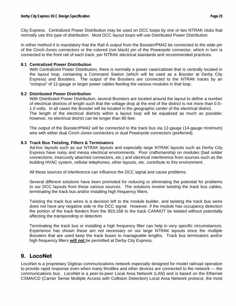
universal worldwide hookup standard for computer networks. LocoNet has been optimized for use with Digitrax systems to allow 100% traffic capacity with less than 0.33% collision rate. LocoNet is the method of interconnecting all parts of a Digitrax DCC system, such as the Command Station, Boosters, Radio and I/R Receivers, Throttles, Universal Panels, Detectors, and other devices. It does not connect to Mobile or Stationary Decoders, which are "connected" via the track. Note, however, that LocoNet does connect to Digitrax DS64 Stationary Decoders. The LocoNet design allows very simple free form wiring, which makes adding extra devices and features simple. The LocoNet cabling at Derby City Express will be extensive and complex due to the size and complexity of the layout. Digitrax has developed a device called the LocoNet Repeater (LNRP) which permits the isolation and protection of segments of the layout, i.e. each loop, and acts as a diagnostic tool when problems arise. The LNRP and its connections are shown below. Each LNRP must be individually powered with 12–18VDC.
LocoNet Repeater LocoNet Repeater Components Photo and diagram source: Digitrax, Inc.
At Derby City Express a two-layer LocoNet protection scheme will be used. A LNRP at the Command Node will protect the Command Station from faults on the spine, while LNRPs at each junction module will protect the spine LocoNet from faults that may occur in each loop. While Loop LNRPs provide protection to boosters, radio receivers, etc. in use in each loop, additional LNRPs may be required along the spine to provide LocoNet protection to these items that may be located on the spine itself. At each Loop LNRP one Standard LocoNet output will be designated for ThrottleNet and the second for BoosterNet, as described in the following sections. The LocoNet jack on the front panel of the LNRPs can be used for throttles only, as there are no RailSync signals at this jack. At Derby City Express use of this jack is reserved for Digital Staff members only; a sticker stating “For DCE Staff use only” will be applied to each LNRP. The LNRP configuration for Derby City Express is shown in the diagram below. More information on the Digitrax LocoNet Repeater (LNRP) module is provided in Appendix D.
Derby City Express DCC Design Specification Page 27
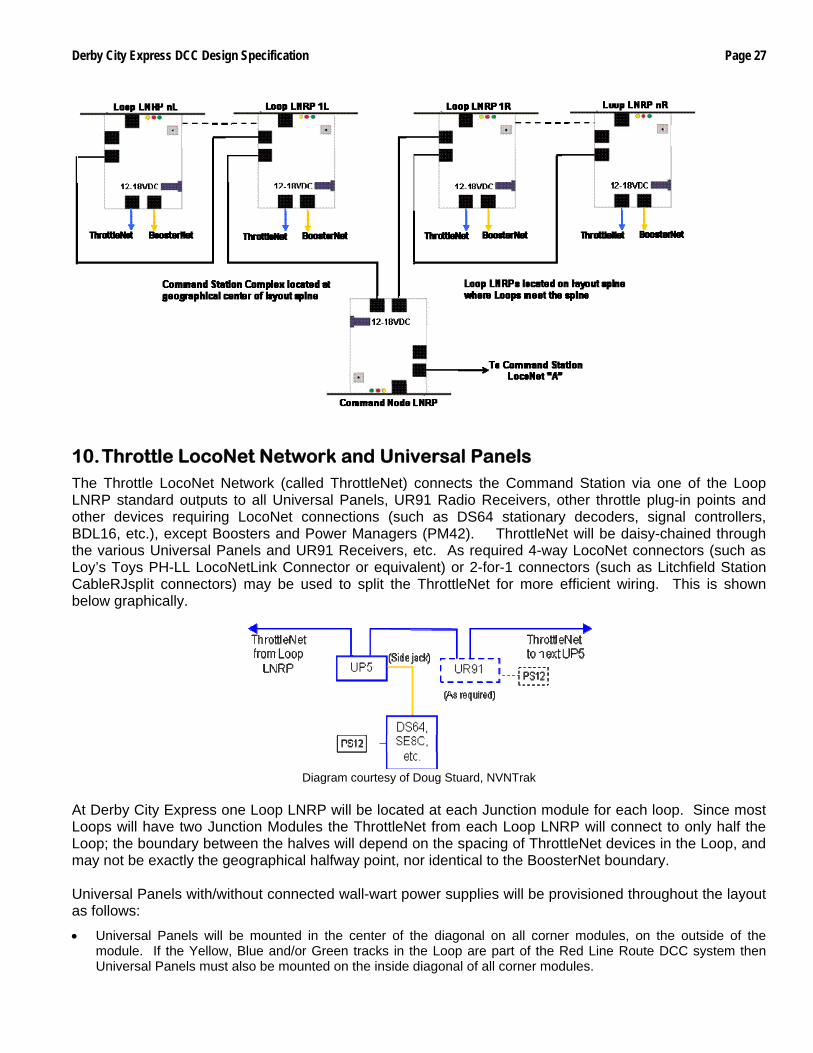
10. Throttle LocoNet Network and Universal Panels The Throttle LocoNet Network (called ThrottleNet) connects the Command Station via one of the Loop LNRP standard outputs to all Universal Panels, UR91 Radio Receivers, other throttle plug-in points and other devices requiring LocoNet connections (such as DS64 stationary decoders, signal controllers, BDL16, etc.), except Boosters and Power Managers (PM42). ThrottleNet will be daisy-chained through the various Universal Panels and UR91 Receivers, etc. As required 4-way LocoNet connectors (such as Loy’s Toys PH-LL LocoNetLink Connector or equivalent) or 2-for-1 connectors (such as Litchfield Station CableRJsplit connectors) may be used to split the ThrottleNet for more efficient wiring. This is shown below graphically.
Diagram courtesy of Doug Stuard, NVNTrak
At Derby City Express one Loop LNRP will be located at each Junction module for each loop. Since most Loops will have two Junction Modules the ThrottleNet from each Loop LNRP will connect to only half the Loop; the boundary between the halves will depend on the spacing of ThrottleNet devices in the Loop, and may not be exactly the geographical halfway point, nor identical to the BoosterNet boundary. Universal Panels with/without connected wall-wart power supplies will be provisioned throughout the layout as follows:
• Universal Panels will be mounted in the center of the diagonal on all corner modules, on the outside of the module. If the Yellow, Blue and/or Green tracks in the Loop are part of the Red Line Route DCC system then Universal Panels must also be mounted on the inside diagonal of all corner modules.
Page 28 Derby City Express DCC Design Specification
• Universal Panels will be mounted along the outside of the layout at approximately 20-foot intervals or less. If the Yellow, Blue and/or Green tracks in the Loop are part of the Red Line Route DCC system then Universal Panels must also be mounted on the inside of the modules at approximately the same intervals.
• Modules equipped with panels or other throttle plug-in devices will be included in ThrottleNet and in the distance calculations, only after being tested for proper operation of the network in the module. Such plug-ins will be covered over with tape and bypassed if they do not test fully operational. Throttle plug-in devices need not be panels manufactured by Digitrax.
• Some clubs have equipped their modules with a LocoNet Bus, with 6-wire jacks at the end of each module. Short LocoNet jumper cables connect the modules. Such LocoNet Bus equipped modules will be utilized as part of ThrottleNet once tested for proper operation in the network. If the on-module LocoNet bus does not function properly, a LocoNet bypass will be added.
Universal Panels that are connected to the Red Line Route DCC system will be marked with a small circular red sticker attached to the panel at the top left front. Universal Panels that are part of an independent DCC system must be marked with yellow, blue and/or green as appropriate. The 6-wire cabling for ThrottleNet will be suspended from the module as it is run throughout the layout. The ThrottleNet cable must not be allowed to hang down where it may be damaged by activity under the modules (such as box storage, entry/exit from the layout, etc.), especially in the vicinity of the RJ plugs. Should the ThrottleNet need to be run on the floor, it must be securely fastened to the floor with suitable tape and not be twisted underneath the tape. The 6-wire cable for ThrottleNet will be white or silver, or have white tape applied at each RJ12 plug. The specific location and quantities of Universal Panels and ThrottleNet routing will be detailed on the final layout drawings available at the Convention. Special Note for Digitrax UP3/UP5 Universal Panels Digitrax UP3 and UP5 Universal Panels serve multiple purposes but they do not add power to the LocoNet, only to the front panel (and side panel in the UP5) RJ jacks for whatever is plugged into them. Thus they will help reduce the load on the LocoNet when batteryless throttles are used and for battery throttles when the battery voltage is low. There are 3 possible power sources for the UP3/UP5 and they can be used singly, or all together. 1) LocoNet Power If the UP3/UP5 is connected only to the LocoNet, then it will only have available LocoNet power.
As such a UP3/UP5 is the same as any other dual RJ connector, and all power drawn will be from LocoNet. (Note that the LNRP adds power to the LocoNets terminated on standard LNRP jacks.)
2) Track Power Connectors When these are connected to local track power they provide power to the front jacks (and side jack on the UP5). There is also a bi-colored LED on the UP3/UP5 that will now show the status of the local track power. This way as long as there is track power, any throttle connected to either of the front jacks (or the side jack on the UP5), will use the track power instead of LocoNet power. Track power, if connected, should only be Red track power. (Universal Panels which are part of an independent loop DCC system should not be connected to Red track power, but rather to Yellow, Blue or Green as appropriate.)
3) A 2mm DC Power Jack Connect a 12–15VDC power source here; a Digitrax PS12 or other 12VDC 300mA wall wart works very well for this. Also located in the rear back center is a solder hole. These solder holes can be connected together from one UP3/UP5 to another, and this will allow the 12VDC to power up to a total of 10 UP3/UP5 panels in a daisy chain fashion. Only this single conductor for the daisy chain is needed because the LocoNet common will supply the return path. If the 12VDC power is connected and always on, even with the systems powered down, the UP3/UP5 can be used as a battery saver for battery throttles as long as they are plugged into the UP3/UP5.
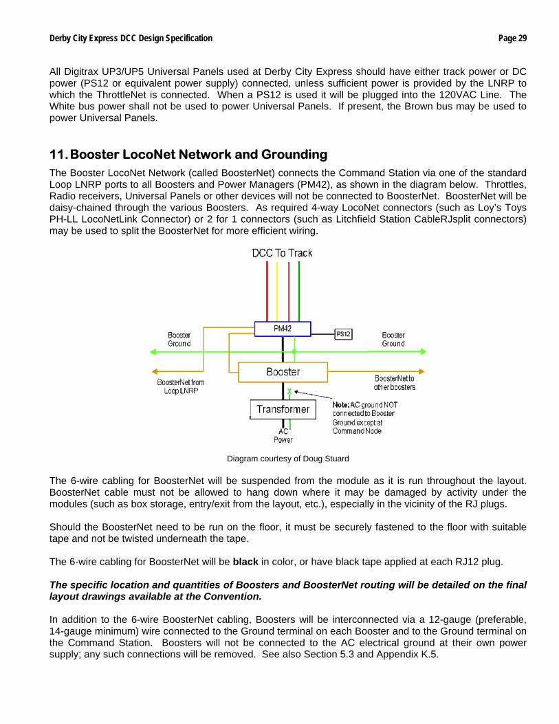
Derby City Express DCC Design Specification Page 29
All Digitrax UP3/UP5 Universal Panels used at Derby City Express should have either track power or DC power (PS12 or equivalent power supply) connected, unless sufficient power is provided by the LNRP to which the ThrottleNet is connected. When a PS12 is used it will be plugged into the 120VAC Line. The White bus power shall not be used to power Universal Panels. If present, the Brown bus may be used to power Universal Panels. 11. Booster LocoNet Network and Grounding The Booster LocoNet Network (called BoosterNet) connects the Command Station via one of the standard Loop LNRP ports to all Boosters and Power Managers (PM42), as shown in the diagram below. Throttles, Radio receivers, Universal Panels or other devices will not be connected to BoosterNet. BoosterNet will be daisy-chained through the various Boosters. As required 4-way LocoNet connectors (such as Loy’s Toys PH-LL LocoNetLink Connector) or 2 for 1 connectors (such as Litchfield Station CableRJsplit connectors) may be used to split the BoosterNet for more efficient wiring.
Diagram courtesy of Doug Stuard
The 6-wire cabling for BoosterNet will be suspended from the module as it is run throughout the layout. BoosterNet cable must not be allowed to hang down where it may be damaged by activity under the modules (such as box storage, entry/exit from the layout, etc.), especially in the vicinity of the RJ plugs. Should the BoosterNet need to be run on the floor, it must be securely fastened to the floor with suitable tape and not be twisted underneath the tape. The 6-wire cabling for BoosterNet will be black in color, or have black tape applied at each RJ12 plug. The specific location and quantities of Boosters and BoosterNet routing will be detailed on the final layout drawings available at the Convention. In addition to the 6-wire BoosterNet cabling, Boosters will be interconnected via a 12-gauge (preferable, 14-gauge minimum) wire connected to the Ground terminal on each Booster and to the Ground terminal on the Command Station. Boosters will not be connected to the AC electrical ground at their own power supply; any such connections will be removed. See also Section 5.3 and Appendix K.5.
Page 30 Derby City Express DCC Design Specification
12. Radio Receivers Radio receivers are needed to receive transmissions form the wireless throttles to be used for controlling trains at Derby City Express. To minimize radio dead spots all receivers will be mounted on a “radio tower” at least 3 feet above the top of the layout module’s skyboards. 12.1 Digitrax UR91 Radio Receivers
Digitrax UR91 Radio receivers will be used to receive transmissions from Digitrax wireless throttles. All UR91 receivers will be powered by PS12 or equivalent 12V wall-wart power supplies. Powering of the UR91s by track power will not be permitted, as a shutdown of track power for any reason will remove power from the UR91. UR91 radio receivers will be connected to ThrottleNet. A minimum of two UR91 radio receivers, tower mounted, will be placed at a appropriate locations in each layout loop. Where a loop uses an independent DCC system any radio receivers for that system should be placed no closer then 10 feet to a Red Line Route radio receiver. The specific location and quantities of Radio Receivers will be detailed on the final layout drawings available at the Convention.
12.2 Digitrax UR91 Receiver Capacity
There may be some concern that the Digitrax specifications for the UR91 states that 10 – 20 throttles can be handled. It should be noted that this refers to throttles broadcasting in the exact same time. It is expected that well in excess of 60 throttles can be handled since it is unlikely that they all send at the same time. Also, unlike a tethered throttle which sends each command once, radio throttles send each command 5 times to make sure that at least one gets through on a busy receiver. Further, while the receivers receive from all throttles within range, the UR91 will filter the messages and only transmit to LocoNet the messages that have the identical LocoNet ID.
12.3 Digitrax UR91 Connections UR9 radio receivers may be connected to the side connector on the nearest ThrottleNet UP5 Universal Panel, or connected inline as part of ThrottleNet.
12.4 Interference from Other Systems
This type of interference is the interference from another source of radio transmission on the same or a close frequency that may be even busier then the traffic from the Digitrax wireless throttles at Derby City Express. For example, a two-way polled system, such as the NCE DCC system, can result in radio channel congestion that becomes disruptive. Since the NCE system is two-way, radio packets received in error generate retransmission requests, so any radio interference to the NCE system from Digitrax throttles will cause more traffic in the NCE system, swamping Digitrax receivers even more. A Digitrax throttle, being transmit only, has no way of knowing that its transmissions have been stepped on, other than the action of the throttle operator who twiddles the knobs even more furiously trying to get a response, thus compounding the problem. The radio protocol and LocoNet protocol (packets, unique to Digitrax) are different, and since the LocoNet protocol is specific to Digitrax and incompatible with the NCE protocol, a UR91 on seeing a transmission originated by NCE would simply ignore it. However, it is possible that an NCE radio signal may interfere with (swamp) the desired Digitrax throttle signals and prevent the reception of Digitrax packets.
Derby City Express DCC Design Specification Page 31
At Derby City Express every attempt should be made to minimize the number of layouts using the NCE system, and locate those that will be present as far away geographically as possible from the main NTRAK layout. Any Loop independent DCC systems using NCE may only be used in tethered mode.
13. Other DCC Devices A variety of accessory products have been developed to work with NMRA compatible DCC systems and with the Digitrax system LocoNet for control of trackside devices. These include stationary decoders, signals, detection units and fast clocks, among others. The use of these DCC controlled accessories on NTRAK layouts can cause some complex problems. Only NMRA compliant and/or LocoNet certified devices will be permitted in the Derby City Express layout. Use of any accessory products MUST be pre-approved by the Digital Master. Such approval will only be given if the use of the product(s) is verified to not cause any interference with the prime objective of the Convention layout — the continuous and reliable operation of trains. 13.1 Device Classes
There are two general classes into which stationary devices fall:
13.1.1 NMRA Compliant Stationary Decoders Accessory decoders that receive an NMRA compliant signal via track input from a Booster.
13.1.2 Non NMRA Compliant Accessory Decoders Accessory devices that receive a signal via the Command Bus connected to the DCC system, essentially LocoNet devices, but other devices in this category exist.
Some stationary devices, such as the Digitrax DS64, meet both definitions, as it takes either an NMRA signal from the track, or a LocoNet signal.
13.2 Potential Problems
For NTRAK modular layouts there are several problems that the module builder, layout planner and Digital Master must consider:
• There may not always be an appropriate signal available.
• There is a good chance that more than one module owner will have chosen to use the same address for a stationary decoder.
• Operators are likely to be unfamiliar with how to operate a module’s accessory decoders using a throttle or other command bus input device.
13.3 Possible Solutions
By examining each problem in more detail solutions can be found. 13.3.1 Appropriate Signals May Not Always be Available
This problem may arise when a module with accessory decoders has been placed in a layout, or in a portion of a layout, where an appropriate signal is not available. This problem may be made worse when some of the tracks on a module are DCC-powered while others are DC-powered. There are two potential sub-issues to be aware of:
Page 32 Derby City Express DCC Design Specification
13.3.1.1 Wiring Accessory Decoders if No Signal Available For NMRA DCC compliant decoders that cannot be wired into the tracks, a separate accessory decoder signal input (such as a module-mounted Booster) is required for these devices. An additional wiring bus should be used for this purpose, so that decoders from multiple modules can be connected together. For accessory decoders that connect via the command bus (LocoNet) there is a need to be able to isolate the decoders on a module from the command bus. This means that except for the Digitrax DS64 any visible throttle jacks on the module framework cannot be used to connect accessory decoders. This is due to the fact that different throttle buses use the same jacks and plugs, but use the wires for different purposes. It is possible the wiring differences may damage or destroy a device.
13.3.1.2 Obtaining an Appropriate Signal
Some NMRA DCC compliant accessory decoders can work off of 12VDC power; simply provide 12VDC to the decoders. For decoders that cannot work off a simple 12VDC power then an appropriate signal must be supplied to the decoders. For NMRA DCC compliant accessory decoders this means a DCC Command Station and Booster must be supplied that can connect to the accessory decoder’s track inputs. Thus if the decoder does not receive its signal from the layout DCC track bus then a device must be provide that provides all the appropriate signals. For LocoNet devices this means there must be a device which can terminate the private LocoNet. This can be a Command Station, devices such as the Digitrax BDL16x series of block occupancy detectors, or a device such as a LocoBuffer connected to a computer. The preferred connection for any Digitrax DS64 stationary decoders used in the Derby City Express layout will be to ThrottleNet, specifically the side jack of the nearest UP5.
13.3.2 More than One Module Owner has Chosen the Same Address for a Stationary Decoder
Having two or more modules containing accessory decoders with the same address can lead to some problems while operating trains. It is not desirable to throw a turnout on one module, only to find that a turnout on another module in a different part of the layout has also been thrown, perhaps causing a derailment. The clear solution to this problem is to coordinate and re-program, as necessary, all the accessory decoders on the layout that have a conflicting address, and this should be done during setup of the layout, prior to the operation of trains. At Derby City Express the Assistant Digital Master — Device ID will be responsible for ensuring there are no conflicting addresses in the layout. As far as possible address assignments will be provided to module owners so programming can be completed before arriving at Derby City Express. Such addresses then need only to be checked during setup. An alternate method, which will NOT be used at Derby City Express, would be to divide the layout into zones where each zone contains non-conflicting accessory decoder addresses. In the extreme a zone could be a single module. While this can provide satisfactory results where only a few modules have accessory decoders, it leads to a poor use of available
Derby City Express DCC Design Specification Page 33
resources when there are a large number of accessory decoder equipped modules, which is likely at Derby City Express.
13.3.3 Operators Unfamiliar with Accessory Decoder Operation
With a wide variety of modules and operators from many locations in the world being part of the Derby City Express convention layout, many operators may be unfamiliar with how to operate an accessory decoder on a module. It is also not practical for a module owner to be present at his/her module throughout the Convention to explain to each new operator how to use each feature of a module. Because of this unfamiliarity a module owner should provide a local control panel(s) for the module. The need to provide a local control panel may influence the choice of accessory decoder. If an accessory decoder does not have built in inputs for local controls these controls may be routed through a computer using appropriate software. Since some operators will use Digitrax UT4R throttles to control their trains, having a local control panel is highly desirable as the UT4R does not have the ability to operate turnouts. Following are some other factors to remember when designing a control panel:
• The control panel should include a physical control device for every device an average operator might need to use (turnouts, uncoupling devices, etc.)
• It should be clear from looking at the panel what device each switch controls and what each indicator is for.
• Don’t confuse operators by putting controls for devices that are automatically controlled.
• It is recommended that a virtual control panel (i.e. a computer screen) NOT be used for controlling these devices.
• If there are signals on the module, it is recommended that a display of some kind be included that echoes the current signal status. A physical panel can be used for this display; a virtual panel should not be used.
• Consider installing a lockout switch for mainline (red, yellow, blue) turnouts if they are useable for mainline operations.
13.4 Preparing for Derby City Express
Owners of modules with stationary decoders need to be prepared to provide the following additional items with the module:
• Documentation for the stationary decoders on each module.
• The minimal hardware needed to provide the proper power and input signals to the decoders if these inputs are not otherwise available.
• A wiring diagram indicating how the decoders are wired. 13.5 Derby City Express Setup and Operations
The following process will be used to evaluate the acceptability of stationary decoders for the Derby City Express DCC layout, and prepare for appropriate programming of these devices.
• The Layout Coordinator, with the assistance of the Loop Coordinators, will collect information from module owners re their modules that include accessory decoders This includes stating specifically what type(s) of decoder(s) are on each of the modules in question, and which contain mainline turnouts.
• The Layout Coordinator will ensure the Digital Master(s) and the Dispatcher(s) have copies of this information.
Page 34 Derby City Express DCC Design Specification
• The Dispatcher will decide which, if any, of the decoders are going to be used for operating the layout.
• The Digital Master will determine the best method of providing the power to the stationary decoders on the layout, taking care that any decoders that are going to be used for operating the layout are powered in a manner acceptable to the operating principles the Dispatcher wants to use for layout operations.
• Where the module owner has mounted a module Booster he/she must provide manufacturer documentation for the Booster, if non-Digitrax. This Module Booster may only be connected to the Digitrax Rail Sync connections (LocoNet wires 1 and 6); this connection must be by means of a plug-and-socket arrangement to permit rapid disconnect for troubleshooting purposes.
13.6 Acceptable Devices
As stated above, only NMRA compliant and/or LocoNet certified devices will be permitted in the Derby City Express layout.
14. Setup and Test A major challenge will be to install, complete and test the various DCC components, cables, etc., that will make up the DCC system, and to do this in the time available after the layout is sufficiently assembled and before operations are scheduled to start. Setting up the Command Station, Boosters, Radio Receivers, Universal Panels and LocoNets will require close coordination and communications among many people. The Digital Team members and Loop DCC Coordinators involved will be equipped with Family Radio Service (FRS) radios set to a unique channel assigned for this purpose. Specific setup responsibilities are as follows:
• The Digital Master will be responsible for setting up the Command Station complex. He will then be overall supervisor of the Digital Team, and coordinate any system testing necessary from the Command Station.
• The Assistant Digital Master — Device ID Manager will be responsible for assigning LocoNet IDs to the various Loops with their own (separate from Red Line Route) DCC system and providing this information to the Loop DCC Coordinator.
He/she will also ensure that all other DCC devices in use on the layout, such as stationary decoders, have unique addresses so they will not interfere with each other.
At other time he/she will then assist the setup teams and the Loop DCC Coordinators as necessary.
• The Assistant Digital Master — Programming will be responsible for ensuring the Programming Stations are setup and operational. At other times he/she will assist the setup teams and the Loop DCC Coordinators as necessary.
• The Assistant Digital Master — Loops/Setup/Teardown will have direct responsibility for installing the various DCC components in the layout spine, utilizing the Setup Teams, and prime responsibility for the installation of the various DCC components around the layout utilizing the Setup Teams and the DCC Loop Coordinators. He/she will also be responsible for providing material needed (e.g. LocoNet cabling, RJ12 jacks, other components) to the setup teams and the Loop DCC Coordinators.
• The Loop DCC Coordinators will be responsible for the physical installation of the DCC system in their loops, according to the rules specified in this document. This includes the Red Line Route system and any other DCC system unique to the Yellow, Blue and/or Green tracks in their loop. Once each Loop installation is complete the Loop DCC Coordinators can use a local Command Station to test their Loop before connecting to the main DCC system.
Derby City Express DCC Design Specification Page 35
Except for locomotives used by the Digital Staff for testing purposes, there should be no locomotives on any of the DCC-powered tracks until setup has been completed and the system activated. No DCC trains should be run until the whole system is complete, except for track cleaning or other trains as authorized by the Digital Master. Locomotives used by the Digital Staff for testing purposes are exempt from any address programming restrictions of Section 8, but must be programmed to 4-digit addresses greater than 8,000. As soon as the layout spine is set up, wired and tested for DCC, the DCC system will be activated. Each layout loop can then be activated as it is completed, wired and tested. 14.1 Setup
The Red Line Route will run around the entire layout. In some Loops some of the Yellow and/or Blue and/or Green tracks may be under DC control or under control of a separate DCC system because this is the desired and normal operation for those attendees in the loop. Crossover tracks between such independent tracks and the DCC-operated tracks (including the Red Line Route) must be embargoed to prevent DC trains from crossing over to the Red Line Route. The method of embargoing the crossover must be physical, such as a red map tack placed between the rails in the crossover. Automated control of such crossovers should be disabled if possible.
14.1.1 Setup Proceedings
The Layout Coordinator, his staff and the Loop Coordinators will be responsible for the physical layout and placement of all modules in the layout. Modules will be inserted and connected to the layout beginning with the layout spine and extending out to the various loops.
14.1.2 Module Inspection All modules destined for the NTRAK layout at Derby City Express must meet the NTRAK Specifications, as a minimum. It will be the responsibility of Clubs with recognized Certification procedures to inspect and certify the modules their Members are bringing to Derby City Express. All other modules will receive a cursory visual inspection on arrival, and before they are assembled into the layout. A suggested procedure for this module inspection is defined in Appendix E. Any deficiencies found will be documented for a more detailed inspection once the problem(s) is remedied by the owner and installed in the layout, but before operations begin. If the module clearly does not meet basic NTRAK, Bend Track, TwinTrak or oNeTRAK standards as appropriate for its position in the layout it will not be permitted in the layout.
14.1.3 Section Isolation
The Digital Staff will indicate and ensure insulating rail joiners are installed properly in the spine so that initially there will be an isolated section to start the DCC system set up and test. This is necessary since some loop modules may arrive later than others and some loops may be set up and ready to start train operations earlier than others. Electrical district boundaries will be marked on layout module diagrams that will be provided to all Loop and Loop DCC Coordinators showing where the block gaps should be located. A card will also be placed on the modules indicating specifically the district boundaries and that insulated rail joiners should be used. The Digital Staff will also check to ensure these block gaps are installed at the specified locations, and that track bus cables underneath are marked (with “do not plug” tags) and left unplugged. The Digital Staff and Loop DCC Coordinators will start installing and testing the DCC components on the various loops as they become complete, on a loop-by-loop basis.
Page 36 Derby City Express DCC Design Specification
14.1.4 Device ID Management
There will be several layouts using the Digitrax DCC system to operate at Derby City Express as well as modules with stationary decoders and/or other devices that require a unique ID to prevent interference with each other. 14.1.4.1 LocoNet Management
Each of these layouts that use radio control must be assigned a separate LocoNet ID so they will not interfere with each other. A maximum of eight (8) LocoNet IDs are available with ID=0 being the default. The LocoNet Manager will assign LocoNet IDs to the various independent Loops, other layouts, and any WGH dealers requiring a LocoNet ID either before the Convention or as the Loops/layouts/dealers “report in.” The Main NTRAK Layout (Red Line Route) will be assigned LocoNet ID=7. Other independent Loops, layouts and dealers will be assigned LocoNet IDs in descending order, with ID=0 being the last assigned. In the event there are more than 8 Digitrax-operated layouts at the Convention, LocoNet IDs may need to be shared. This will be done based on size (small can be shared) and geographic diversity (distance between nearest UR91s). It may also be done using address blocks, with one layout assigned, say, addresses 1000–4000, and another assigned addresses 6,000–9,000. Special note for independent DCC systems in the main NTRAK Layout: Irrespective of the LocoNet ID assigned to the system, the range of addresses that include convention registration numbers will be excluded from independent use by the DCC system. This is done so that convention attendees can use the same addresses on the main NTRAK layout and on any loops with independent DCC tracks. From time-to-time during the Convention, the LocoNet Manager will monitor each Loop/layout to ensure they are actually using the ID assigned. DCE Layout Staff will advise World’s Greatest Hobby (WGH) on Tour management of this necessary action, as WGH is the coordinator of the other show layouts. The procedure for LocoNet Management is provided in Appendix F.
14.1.4.2 Device ID Management
Each DCC device — whether mobile or stationary decoders, signal controllers, block detectors, etc. — must have a unique address not shared by any other such device. Except for mobile decoders, checking existing addresses, reprogramming to a unique address and checking the new address for satisfactory operation, as well as keeping a record of assigned addresses, must be done during the setup phase. Appendix G provides a listing of the Sensor and Switch Address Ranges for Digitrax devices other than mobile decoders. The Device ID Manager will ask each module owner with a module equipped with a device that requires an address what the existing programming is for the module device(s). Once this is complete the Device ID Manager will then determine which devices need to be re-programmed, determine a suitable address(es) and work
Derby City Express DCC Design Specification Page 37
with the module owner to do the programming, and to verify operation after programming is complete. He will also record the assigned address(es). In the programming of devices the Device ID Manager will use a laptop computer equipped with a LocoBuffer interface and the LocoNet Checker and/or JMRI LocoTools software needed to program these devices
14.2 Command Station Complex Setup If the Command Station internal battery has not been replaced within the week previous to the Convention, begin by replacing this battery (Type CR2032 Lithium Coin Cell). The active and backup Command Stations will be set on a table located at a central location on the spine of the DCC layout. The power supplies of both Command Stations will be plugged into an Uninterruptible Power Supply (UPS), which in turn will be connected to the 120VAC supply to the layout. A DT400 throttle, with a known good 9V battery installed, will be connected to each Command Station at all times for monitoring and control purposes. The computer used to monitor the Command Station will also be located on this table and plugged into the UPS. Once the Command Stations are installed, they will be powered up and a total system reset (CV39=”c”) carried out. The procedure for a total system reset is provided in Appendix H, Section H.1. After the total system reset is complete, the Command Station will be programmed with the various CVs specified for normal operations as defined in Appendix H, Section H.2.
14.3 Manufacturing and Testing LocoNet Cables LocoNet cables utilize 6-wire telephone/data-type flat or round wire with RJ12 plugs on each end. Using flat cable they can be easily manufactured to meet the specific needs of the Derby City Express layout. The actual wiring of the LocoNet is a balanced RF Quad configuration, which is what allows the free-form non-terminated architecture. This information needed to manufacture, operate, maintain and repair LocoNet cables is provided in Appendix I. Note: The use of standard Ethernet cable for LocoNet applications is prohibited. The
voltages do not match, the pinout does not match, the cabling is different, the RJ plug is different, and the protocols are different.
14.4 ThrottleNet Setup
Each ThrottleNet branch will extend outwards from each Loop LNRP. The branch will be subdivided and daisy-chained throughout the Loop to efficiently connect to all Universal Panels, other throttle connection jacks and UR91 radio receivers.
A specific ThrottleNet routing plan will be detailed on the final layout drawings. Existing white/silver LocoNet cabling can be used where the length matches what is needed. Otherwise new cable will be constructed using a spool of white/silver 6-wire flat cable, an appropriate crimping tool(s) and RJ12 plugs. In either case, each cable will be checked for integrity using a network cable tester. Refer to Appendix J for details and setup procedures.
14.5 BoosterNet Setup
Each BoosterNet branch will extend outwards from each Loop LNRP. The branch will be subdivided and daisy-chained throughout the layout to efficiently connect to all Boosters and PM42s.
Page 38 Derby City Express DCC Design Specification
A specific BoosterNet routing plan will be detailed on the final layout drawings. Existing black LocoNet cabling can be used where the length matches what is needed. Otherwise new cable will be constructed using a spool of black 6-wire flat cable, an appropriate crimping tool(s) and RJ12 plugs. In either case, each cable will be checked for integrity using a network cable tester. Refer to Appendices J and K for BoosterNet details and setup procedures.
14.6 Testing the DCC System Once the Command Station complex is set up and operational it will be used to test and check the DCC system as the spine and the various Loops are installed. Once all Boosters are installed on the spine these Boosters will be properly phased. They will then be the standard for phasing the Boosters in the Loops. Refer to Appendix K for information on Booster phasing and grounding.
15. Operations Once set up is complete the layout enters operational mode, which must be sustained until the Convention is over and tear down begins. 15.1 Power-Up Sequence
To ensure proper operation, the power up sequence is to power the Command Station before any of the Boosters. This ensures all Booster will see LocoNet p[packets on power-up and enter DCC mode. Refer to Appendix L for the Power Up procedure.
15.2 Layout Operations
Like a prototype railroad, certain activities must be carried out on a model railroad to ensure continuous reliable and safe operation. These include activities relating to the track structure, rolling stock and locomotives, and the control equipment.
15.2.1 Track and Wheel Cleaning
Clean track, clean turnout points and clean wheels are fundamental to reliable operation. Refer to Appendix M.
15.2.2 Command Station
It is very important that analog locomotive operations be disabled (OPSW#20 = c) and the speed of address 00 set to 00 during normal layout operations. The stretched pulses generated when using analog address 00 consume system bandwidth rapidly as the speed of address 00 is increased. The pulse width of normal DCC pulses (OPSW#20 = c, address 00 speed=00) is 95μS. Analog operations allow this 95μS to be stretched up to 12000μS, which means that fewer packets can be sent per second, thus cutting bandwidth and slowing response to throttle commands.
15.2.3 Radio Throttles
By design radio throttles act slightly different from normal tethered throttles. They do not send commands until the throttle is inactive. This means that when the engineer is changing speed, direction or setting functions, etc., the throttle does not transmit the commands to the radio receiver until the engineer stops making changes. This gives the effects of delays, but what it is doing is keeping radio data to a minimum to allow maximum bandwidth over the airwaves.
Derby City Express DCC Design Specification Page 39
User education is necessary here. If the user learns to not be constantly changing throttle speed, etc. but do it either in small steps, or all at once to reach a stable state on the throttles he will hardly notice this effect. On the other hand, the more active the user is with the throttle, the more pronounced it becomes. Also, the human body can act as a shield to the radio signals. Thus the user should keep the throttle about 10 inches out from his/her body and try not to get his/her body between the throttle and a radio receiver. Additional radio bandwidth can be obtained, if necessary, by turning off ballistic tracking on all throttles and using the Up and Down buttons to change speed instead of the throttle knobs.
15.2.4 LocoNet Bus Speed
The LocoNet used in the Digitrax system is similar to Ethernet in a computer system, but its speed is 16.6Kbps. With LocoNet, even if all memory slots are active, every known LocoNet device connected and every LocoNet message in use, the actual LocoNet would be at less than 30% capacity. With 100% traffic, there should only be about a 1 in 300 collision rate. The capacity of the LocoNet bus should not be an issue for the Derby City Express layout.
15.3 System Reset In the event major control problems are encountered such as an all slots full condition or other corruption of the Command Station slot memory, and the releasing of slots using the LocoNet Checker or JMRI LocoTools Slot Monitor (as described in Appendix N) does not clear the problem, it may be necessary to perform a partial or full system reset. This process should only take about one minute, but it requires shutting down the DCC tracks. After the reset is performed all locomotive addresses including any UniVersal consists may need to be reprogrammed into the system. The on-duty Digital Master will advise all operators prior to a system reset, and then advise operators what actions they need to take (i.e. logging back onto the system) after the reset is complete. See Appendix H for the process.
15.4 System Shut Down
System Shut Down is a controlled process to prevent runaways or other conditions with trains on the DCC-controlled tracks. Refer to Appendix L for the Shut Down Process.
16. Monitoring, Measuring and Troubleshooting To ensure the continuous and reliable operation of trains, the DCC system will be monitored on a continuous basis throughout the Convention. A computer with appropriate software located next to the Command Station will be connected to the system and used for this purpose. Also, there may be occasions where it will be necessary to measure voltage and/or current on the tracks and track power wiring. This requires a true RMS AC meter. In addition, should something go wrong, procedures need to be in place to handle any problems and ensure a speedy resolution. 16.1 System Monitoring
The most important function at the Command Station to ensure reliable and continuous operation is to monitor the DCC system, specifically the Command Station memory slots, and to take corrective action when warranted, either due to a problem or by engineers running unauthorized addresses. There are two software programs that can be used for monitoring the Command Station.
Page 40 Derby City Express DCC Design Specification
16.1.1 LocoNet Checker LocoNet Checker is software available from the Digitrax web site that allows the management of Digitrax devices connected to the LocoNet bus and monitor their behavior. Key functional areas are:
• Smart configuration of the Command Station, and the ability to make changes quickly.
• Configuration of detectors, power managers and signal controller devices connected to the LocoNet.
• LocoNet and BDL/DS message viewer.
• Manual sending of LocoNet messages.
• Smart Slot Manager that provides information and control of all Command Station slots, including consisted locomotives, throttle ID, function switch status, speed, etc. There is the capability to stop or release individual or all addresses.
LocoNet Checker may be used to monitor the Digitrax Chief Command Station slots, and for setup and changing Digitrax devices. Refer to Appendix N for details.
16.1.2 JMRI: A Java Model Railroad Interface
JMRI is well known for its superior DecoderPro decoder programming tool. As well as DecoderPro, JMRI has developed a library of LocoNet-specific tools (LocoTools) that interface to specific hardware of the DCC system. These may be used to monitor the Digitrax Chief Command Station slots and configure Digitrax DCC devices. Refer to Appendix N for details.
16.1.3 Monitor Computer
The computer to be used will be a Windows-based desktop or laptop computer running Microsoft Windows 2000, XP or Vista. Interface to LocoNet will be via the Digitrax MS-100 interface or the LocoBuffer interface; the LocoBuffer is the preferred interface.
16.2 Measuring and Monitoring Voltage and Current
Since the DCC waveform is square-wave alternating current, and not DC or sine-wave AC, a true RMS meter is required to accurately read DCC voltage and current. The meter to be used at Derby City Express for this purpose is the RRampMeter, designed by Tony’s Train Exchange. The RRampMeter will be used for measuring voltage drop and loss, and for monitoring voltage and current as necessary on the layout track and track power wiring. Refer to Appendix N for details.
16.3 Other Test Equipment
Several other items can be useful for testing during layout setup, and for problem resolution during operations; details are in Appendix N These are:
• Digitrax LT-1 LocoNet Tester The LT-1 LocoNet tester can be used to check the status of LocoNet simply by plugging a short LocoNet cable into the LT-1, and then plugging the cable into a Universal Panel jack. Normal conditions would be three or four LEDs lit. See Appendix N for more details on using the LT-1. Note: the LT-1 is not a LocoNet device, and should NOT be used during normal operations except when troubleshooting.
• Model Power Test Light This device provides a quick test of whether track power is on or off. Just hold the copper prongs across the rail and the light will illuminate if track power is on. This tester does not provide any information about the status of the DCC signal, only whether track power is on or off.
Derby City Express DCC Design Specification Page 41
• Model Power Test Light (Modified) If the Model Power tester is modified by replacing the stock lamp with a bi-color 2-lead LED in series with a 1,000 ohm resistor, then it can be used to check polarity of the DCC track power.
• LED Test Light with Alligator Clips This is simply a 2-lead bi-color LED in series with a 1,000 ohm resistor terminated on alligator clips, with heat-shrink tubing over the resistor and leads near the LED. The length of the leads can be 3”– 6”.
This tester can be used to check track power status, Booster phasing, track power polarity (when address 00 is active and set to a high speed setting), and shorts.
16.4 Troubleshooting In the event problems are encountered during the Convention, procedures must be in place to test the problem and related equipment, then rectify the problem and/or replace the faulty equipment. A great deal of information on troubleshooting and resolving problems is provided in Appendix O. Problems should be reported to the on-duty Digital Master, who will either resolve or assign Digital Team staff to resolve.
17. Tear Down When Derby City Express ends at 5:00pm on Sunday, June 29, 2008, operations on the layout must be shut down and the layout disassembled, and modules packed up and removed from the site. At 5:00pm track power will be turned off at the Command Station, but the Command Station will remain powered until all Boosters are powered off. The DCC Loop Coordinators and Setup/Teardown teams will act expeditiously to disconnect all components of the DCC system — Boosters, PM4s, UPs, UR91s, PS12s, LNRP, ThrottleNet and BoosterNet cabling, and associated hardware — and remove them from the layout. As DCC components are disconnected and removed from the layout they will be taken to a central marshalling point. Once all components have been collected they will be sorted by owner, according to the identification applied at the start of setup (see next Section). When this is complete owners may claim their property. 18. Equipment and Material List The following is a list of equipment and supplies that must be on hand for Derby City Express (DEC) by the start of setup. DCE will be responsible for ensuring the provision of these items, but not necessarily for providing them. DCE will provide a secure marshalling point at the layout site for the assembly of equipment, material and tools. Only the Digital Staff will have access to this equipment. The Assistant Digital Master — Loops/Setup/Tear Down will be responsible for ensuring the registration, identification and marking of all equipment loaned by attendees and/or clubs participating in Derby City Express. In particular any equipment loaned by Digitrax must be clearly identified with a serial number on a removable label for purposes of inventory control before, during and after the Convention.
Page 42 Derby City Express DCC Design Specification
18.1 Equipment The following DCC equipment will be needed during Derby City Express. Specific quantities will be specified as soon as possible in a separate document. 18.1.1 Command Stations
Digitrax Super Chief Command Stations — Qty 5+ (Active/Backup/Programming x3) — DCS100, DCS200 or DCS50 (Programming Station only), with appropriate power supply.
18.1.2 Boosters Digitrax Boosters (with appropriate power supply) — the following are acceptable: • DCS100 (in Booster only mode with fresh CR2032 battery) • DCS200 (in Booster only mode with fresh CR2032 battery) + PM42 • DB100, DB100a, DB100+ • DB150 (in Booster only mode) • DB200, DB200+ and PM42 • DCS50 (in Booster only mode)
18.1.3 Digitrax DCC Devices
• Digitrax LocoNet Repeater + PS-12 power supply • Digitrax Radio Receivers — UR91 + PS12 power supply • Digitrax Power Managers — PM4/PM42 + PS12 power supply • Digitrax Universal Panels + Power — UP3/UP5 + PS12 power supply • Loy’s Toys PH-LL – LocoNet 4-way Connector • Loy’s Toys PH-UP – LocoNet Universal Panel • Digitrax LocoNet Tester — LT1 • Digitrax PR2 Programmer
18.1.4 Other Equipment
• Uninterruptible Power Supply (UPS) • Personal Computers running Windows Operating System • LocoBuffer Computer Interface and/or Digitrax MS100 Computer Interface and/or
Digitrax PR3 programmer • LocoNet Checker and/or JMRI LocoNet Tools software • JMRI DecoderPro software
18.2 Material
The following material will be needed during Derby City Express. Specific quantities will be specified as soon as possible in a separate document. 6-wire Flat Telephone Cable, Color 1 (ThrottleNet) — white/silver 6-wire Flat Telephone Cable, Color 2 (BoosterNet) — black White and/or black tape to ID cables if only one color 6-wire cable purchased RJ12 Plugs for above cable 12-gauge solid wire for system ground, green color preferred. Polarity Change Cables Ties to fasten LocoNet cables under modules. Suitable ties are:
Plastic wire tires Twist Ties (e.g. for sandwich bags, garbage bags) Plastic twist ties
Cinch-Jones Connectors Powerpole Connectors 12-gauge zip wire (outdoor low-voltage wire)
Derby City Express DCC Design Specification Page 43
16-gauge zip wire Radio Towers Power Strips CR2032 Lithium Coin Cells No. 4 x ½” round-head wood screws for fastening Universal Panels to modules. Elastic Bands Red Map Tacks Tags for attaching to Cinch-Jones & Powerpole connectors. Red dot stickers to label Red Line Route Universal Panels. Yellow, blue, green dot stickers to label independent Loop DCC systems Atlas or Peco Insulated Rail Joiners Clear Nail Polish Duct Tape 320-Grit Black Wet/Dry Emery Paper Atlas Conducta Lube Isopropyl Alcohol 3M Dual-Bladed Guillotine Insulation Displacement Connectors (IDC)
18.3 Miscellaneous Tools
Diagonal Wire Cutters Wire Stripper Long-Nosed Pliers Screwdrivers — Flat and Phillips — Miscellaneous Sizes Soldering Irons (15W, 25W) and solder Network Cable Tester 6-Wire Crimping Tool Powerpole Connector Crimping Tool Bi-Color LED with 1,000 ohm resistor and leads with alligator clips.
19. References Much of the information contained in this document is the result of direct experience learned from various large NTRAK layouts, beginning with the first uNcoNveNtioN held in Richmond, VA in 1999, and especially from the large Capitol Limited layout at Chantilly, VA in 2004. Specifically, Doug Stuard of NVNTRAK has provided direct assistance in the review of this specification, in providing suggestions, corrections and sections of text, plus many diagrams. Many specific parameter values specified are the result of an extensive series of tests carried out on various NTRAK show layouts over the past several years. Other sources for information are extensive correspondence on various Yahoogroups email lists, including:
DCC-Sound Digitrax Sound NTRAK Wiring Connectors DCC 4 Everyone JMRI Users QSIndustries DCC for All LocoNet Hackers Railroad and Co. DCC for Fun NDCC SoundTraxx DCC SIG N Scale Wiring for DCC Digitrax NTrakDCCSIG Winlok
Page 44 Derby City Express DCC Design Specification
Specific correspondence with several people:
Doug Stuard, NVNTRAK Bill Royse, NRMRC Martin Myers, BANTrak David Thompson, NRMRC Mike Curtis, Nashville NTRAK
Diagrams courtesy of Doug Stuard, Digitrax, Inc., Train Buddy Products, LocoNet Checker and JMRI. Technical Assistance provided by Digitrax.
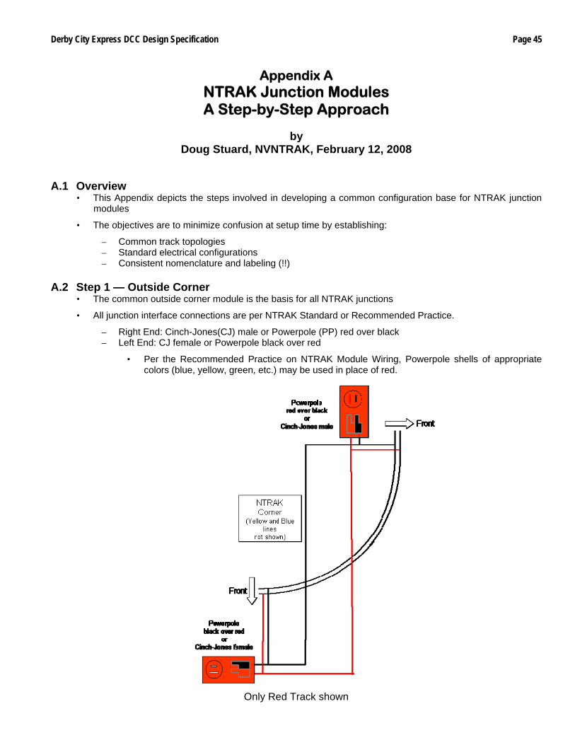
Derby City Express DCC Design Specification Page 45
Appendix A NTRAK Junction Modules A Step-by-Step Approach
by
Doug Stuard, NVNTRAK, February 12, 2008 A.1 Overview
• This Appendix depicts the steps involved in developing a common configuration base for NTRAK junction modules
• The objectives are to minimize confusion at setup time by establishing:
– Common track topologies – Standard electrical configurations – Consistent nomenclature and labeling (!!)
A.2 Step 1 — Outside Corner
• The common outside corner module is the basis for all NTRAK junctions
• All junction interface connections are per NTRAK Standard or Recommended Practice.
– Right End: Cinch-Jones(CJ) male or Powerpole (PP) red over black – Left End: CJ female or Powerpole black over red
• Per the Recommended Practice on NTRAK Module Wiring, Powerpole shells of appropriate colors (blue, yellow, green, etc.) may be used in place of red.
Only Red Track shown
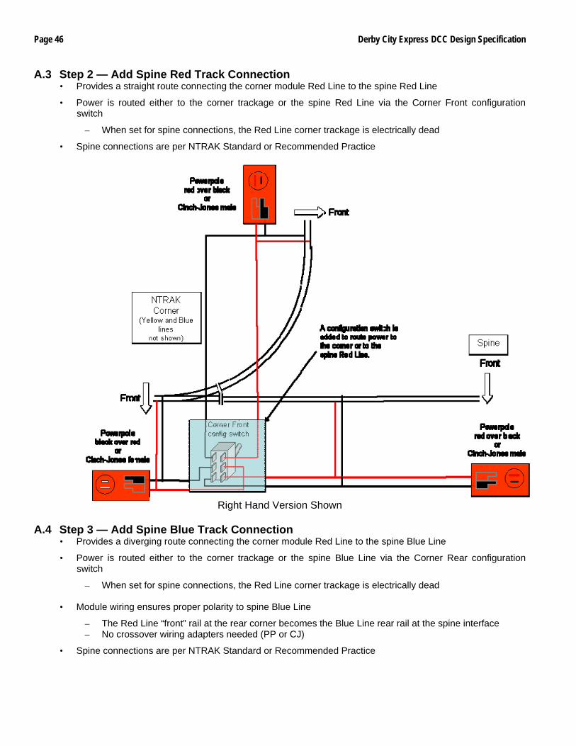
Page 46 Derby City Express DCC Design Specification
A.3 Step 2 — Add Spine Red Track Connection • Provides a straight route connecting the corner module Red Line to the spine Red Line
• Power is routed either to the corner trackage or the spine Red Line via the Corner Front configuration switch
– When set for spine connections, the Red Line corner trackage is electrically dead
• Spine connections are per NTRAK Standard or Recommended Practice
Right Hand Version Shown A.4 Step 3 — Add Spine Blue Track Connection
• Provides a diverging route connecting the corner module Red Line to the spine Blue Line
• Power is routed either to the corner trackage or the spine Blue Line via the Corner Rear configuration switch
– When set for spine connections, the Red Line corner trackage is electrically dead
• Module wiring ensures proper polarity to spine Blue Line
– The Red Line “front” rail at the rear corner becomes the Blue Line rear rail at the spine interface – No crossover wiring adapters needed (PP or CJ)
• Spine connections are per NTRAK Standard or Recommended Practice
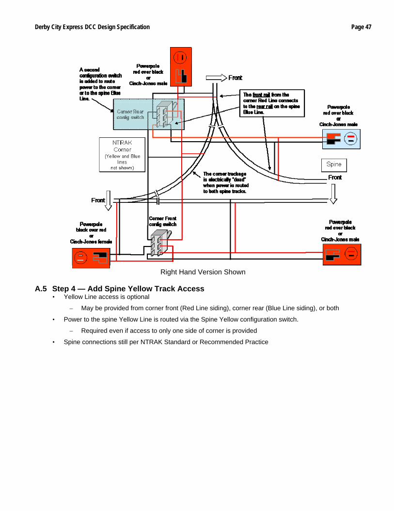
Derby City Express DCC Design Specification Page 47
Right Hand Version Shown
A.5 Step 4 — Add Spine Yellow Track Access
• Yellow Line access is optional
– May be provided from corner front (Red Line siding), corner rear (Blue Line siding), or both
• Power to the spine Yellow Line is routed via the Spine Yellow configuration switch.
– Required even if access to only one side of corner is provided
• Spine connections still per NTRAK Standard or Recommended Practice
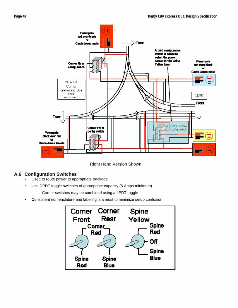
Page 48 Derby City Express DCC Design Specification
Right Hand Version Shown
A.6 Configuration Switches
• Used to route power to appropriate trackage
• Use DPDT toggle switches of appropriate capacity (6 Amps minimum)
– Corner switches may be combined using a 4PDT toggle
• Consistent nomenclature and labeling is a must to minimize setup confusion
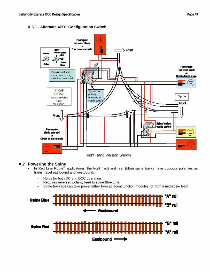
Derby City Express DCC Design Specification Page 49
A.6.1 Alternate 4PDT Configuration Switch
Right Hand Version Shown
A.7 Powering the Spine
• In Red Line Route© applications, the front (red) and rear (blue) spine tracks have opposite polarities as trains travel eastbound and westbound.
– Holds for both DC and DCC operation – Requires reversed polarity feed to spine Blue Line – Spine trackage can take power either from adjacent junction modules, or from a mid-spine feed.
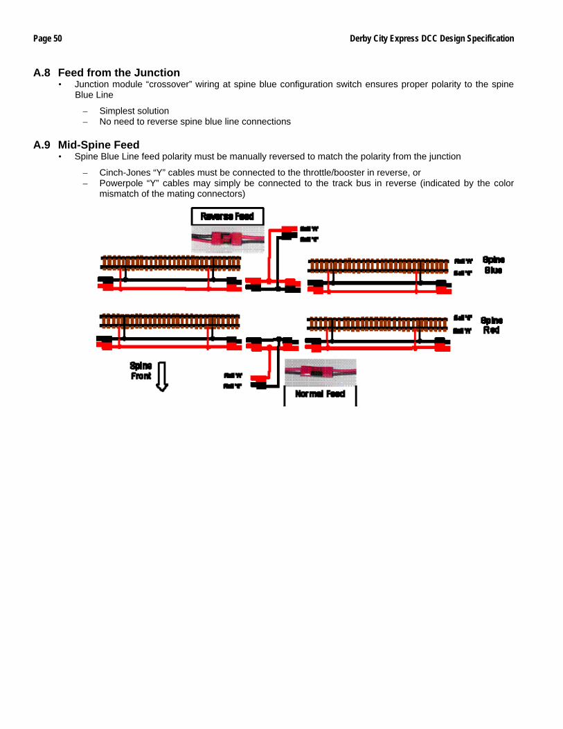
Page 50 Derby City Express DCC Design Specification
A.8 Feed from the Junction • Junction module “crossover” wiring at spine blue configuration switch ensures proper polarity to the spine
Blue Line
– Simplest solution – No need to reverse spine blue line connections
A.9 Mid-Spine Feed
• Spine Blue Line feed polarity must be manually reversed to match the polarity from the junction
– Cinch-Jones “Y” cables must be connected to the throttle/booster in reverse, or – Powerpole “Y” cables may simply be connected to the track bus in reverse (indicated by the color
mismatch of the mating connectors)
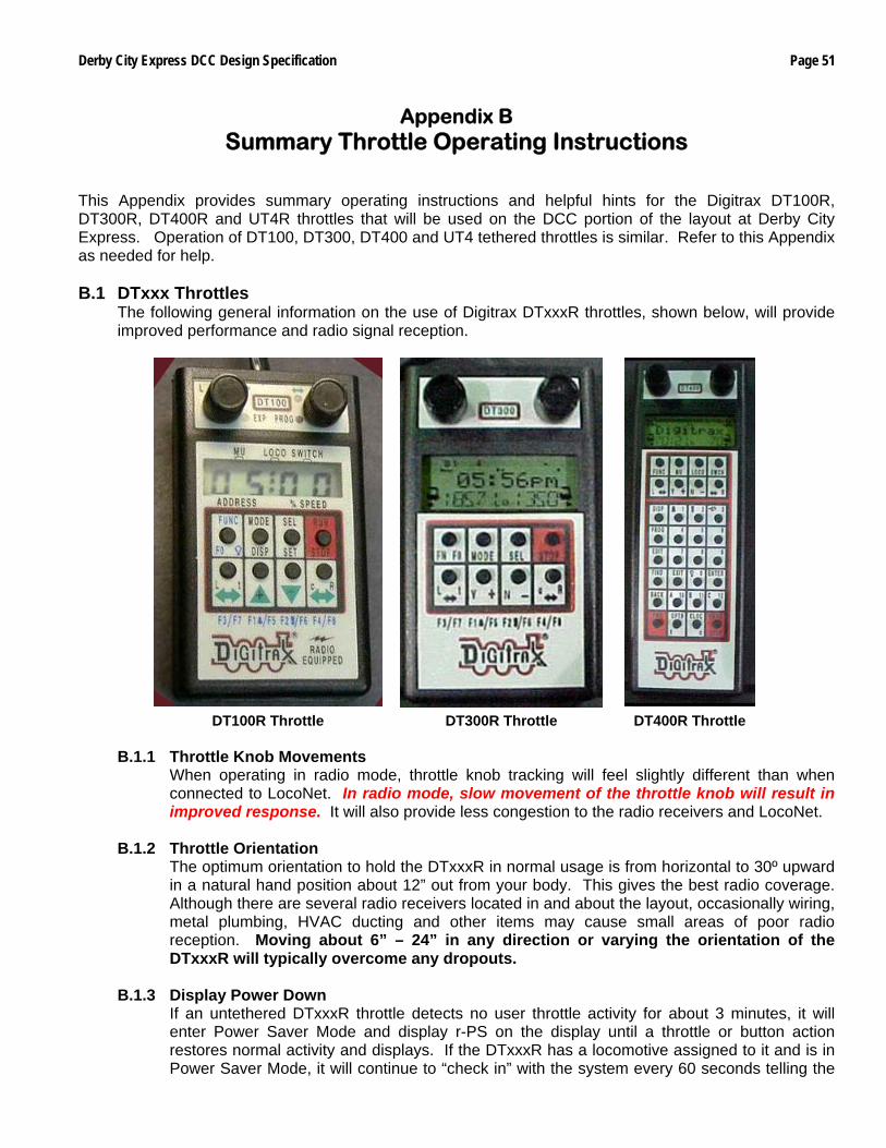
Derby City Express DCC Design Specification Page 51
Appendix B Summary Throttle Operating Instructions
This Appendix provides summary operating instructions and helpful hints for the Digitrax DT100R, DT300R, DT400R and UT4R throttles that will be used on the DCC portion of the layout at Derby City Express. Operation of DT100, DT300, DT400 and UT4 tethered throttles is similar. Refer to this Appendix as needed for help. B.1 DTxxx Throttles
The following general information on the use of Digitrax DTxxxR throttles, shown below, will provide improved performance and radio signal reception.
DT100R Throttle DT300R Throttle DT400R Throttle
B.1.1 Throttle Knob Movements
When operating in radio mode, throttle knob tracking will feel slightly different than when connected to LocoNet. In radio mode, slow movement of the throttle knob will result in improved response. It will also provide less congestion to the radio receivers and LocoNet.
B.1.2 Throttle Orientation
The optimum orientation to hold the DTxxxR in normal usage is from horizontal to 30º upward in a natural hand position about 12” out from your body. This gives the best radio coverage. Although there are several radio receivers located in and about the layout, occasionally wiring, metal plumbing, HVAC ducting and other items may cause small areas of poor radio reception. Moving about 6” – 24” in any direction or varying the orientation of the DTxxxR will typically overcome any dropouts.
B.1.3 Display Power Down
If an untethered DTxxxR throttle detects no user throttle activity for about 3 minutes, it will enter Power Saver Mode and display r-PS on the display until a throttle or button action restores normal activity and displays. If the DTxxxR has a locomotive assigned to it and is in Power Saver Mode, it will continue to “check in” with the system every 60 seconds telling the
Page 52 Derby City Express DCC Design Specification
system “I’m still here.” This keeps the system from releasing the locomotive back to “common.” The easiest and fastest way to signal the DTxxxR to exit from Power Saver Mode is to hold down either the + or – button. Optionally you can disable Power Down. Note: Some consider that a loss of radio control is tied to the Power Saver Mode being active in the throttle, and recommend that this Mode be disabled. Operators may use either Mode at Derby City Express. The procedure to change throttle options is in Section B.2.7.
B.2 DTxxx Throttle Operations
B.2.1 Select Locomotive to Drive
DT100R Throttle DT300R Throttle DT400R Throttle • DT100R must be connected to LocoNet. • Turn desired throttle knob at least ¼ turn in
either direction until display shows SE:L-. • To select 2-Digit Address, press SEL/SET.
Display shows 00:03 with “00” flashing. Turn either throttle knob until desired locomotive address appears on display. Press SEL/SET to set address active.
• To select 4-Digit Address, press and hold SEL/SET then turn one throttle knob. DT100R enters 4-digit address range & RED EXP indicator lights. Select 4-digit address (left knob changes in hundreds, right in units). Press SEL/SET to set address active.
• DT300R must be connected to LocoNet. • Turn desired throttle knob at least ¼ turn in
either direction or press down on knob. • Press SEL/SET; Loco icon flashes. • To select 2-Digit Address turn left throttle knob
so “00” appears in display, then use right knob to dial up desired address. Press SEL/SET to set address active.
• To select 4-Digit Address use left throttle knob to dial up first 2 digits (1000’s & 100’s) &right knob to dial up last two digits (10’s & 1’s). Press SEL/SET to set address active.
• DT400R must be connected to LocoNet. • Turn desired throttle knob at least ¼ turn in
either direction. • Press LOCO. Display shows SEL under
activated knob. • Use the numeric keypad to enter the desired
address (either 2-digit or 4-digit) • Press LOCO to select the address. The loco
icon associated with the throttle knob shows a direction arrow and blinking smoke. The blinking smoke indicates which throttle knob is associated with the top line of the display.
B.2.2 Controlling Lights and Functions
DT100R Throttle DT300R Throttle DT400R Throttle • Press FUNC/F0 to get to Light/Function mode
for display active throttle. Display shows Fn:00 with n flashing to indicate the function number of desired function needs to be selected.
• Use one of five BLUE buttons to choose desired function. FUNC/F0 controls lights. Pressing FUNC/FO toggles light from off (F0:of) to on (F0:on) to off, etc.
• Operation is the same for other functions F1, F2, F3, and F4.
• To access functions F5–F7 press & hold FUNC/F0 while pressing the BLUE F5, F6, F7 or F8 buttons to toggle between on & off.
• Adjust either throttle to return to Loco mode.
• Press FUNC/F0 button to get to Light/Function mode for display active throttle. Display shows Fn:00 with n flashing to indicate the function number of desired function needs to be selected.
• Use one of five BLUE buttons to choose desired function. FUNC/F0 controls lights. Pressing FUNC/FO toggles light from off (F0:of) to on (F0:on) to off, etc.
• Operation is the same for other functions F1, F2, F3, and F4.
• To access functions F5–F7 press & hold FUNC/F0 while pressing the BLUE F5, F6, F7 or F8 buttons to toggle between on & off.
• Adjust either throttle to return to Loco mode.
• Ensure the throttle knob to be used is in normal function mode, as it is during normal locomotive operations. If not sure press FUNC.
• For the light function (F0) press the LAMP 0 button to toggle F0 on and off.
• For functions 1–12 press the button on the numeric keypad that corresponds with the desired function to be turned on/off. Note that F2 is a non-latching function and only is on as long as button 2 is held down. To latch F2 hold down button 2 then press the PWR button then release both simultaneously.
B.2.3 Locomotive Speed and Direction Control
DT100R Throttle DT300R Throttle DT400R Throttle • Turn throttle knob for locomotive whose speed
is to be changed. UP/+ & DOWN/- can also be used.
• With 2-digit address speed is shown on right side of display.
• With 4-digit address speed flashes up as SP:XX. Display will return to 4-digit address.
• To change direction press c/R for right throttle knob or L/t for left throttle knob. Direction indicator changes color (to RED for reverse or GREEN for forward.)
• Turn throttle knob for locomotive whose speed is to be changed. Y+ & N- buttons can also be used.
• % of full speed will be displayed in text line of display on the L or R side depending on throttle knob that is controlling locomotive. % of full speed is also displayed on bar graph above the text area in the display.
• To change direction double click the Throttle Knob controlling locomotive or press the L or R Reverse button.
• Turn throttle knob for locomotive whose speed is to be changed. The Y+ and N- buttons can also be used.
• % of full speed will be displayed in text line of display on the L or R side depending on throttle knob that is controlling locomotive. % of full speed is also displayed on bar graph above the text area in the display.
• To change direction double click the Throttle Knob controlling locomotive or press the L or R Reverse button.
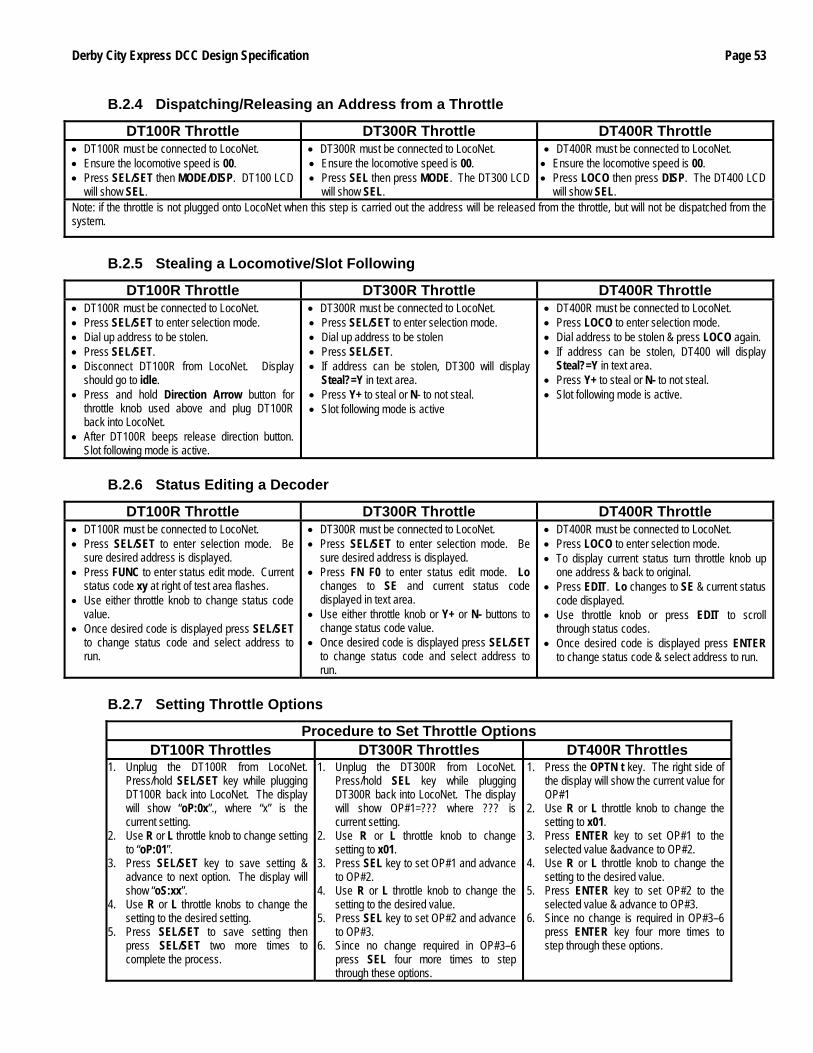
Derby City Express DCC Design Specification Page 53
B.2.4 Dispatching/Releasing an Address from a Throttle
DT100R Throttle DT300R Throttle DT400R Throttle • DT100R must be connected to LocoNet. • Ensure the locomotive speed is 00. • Press SEL/SET then MODE/DISP. DT100 LCD
will show SEL.
• DT300R must be connected to LocoNet. • Ensure the locomotive speed is 00. • Press SEL then press MODE. The DT300 LCD
will show SEL.
• DT400R must be connected to LocoNet. • Ensure the locomotive speed is 00. • Press LOCO then press DISP. The DT400 LCD
will show SEL. Note: if the throttle is not plugged onto LocoNet when this step is carried out the address will be released from the throttle, but will not be dispatched from the system.
B.2.5 Stealing a Locomotive/Slot Following
DT100R Throttle DT300R Throttle DT400R Throttle • DT100R must be connected to LocoNet. • Press SEL/SET to enter selection mode. • Dial up address to be stolen. • Press SEL/SET. • Disconnect DT100R from LocoNet. Display
should go to idle. • Press and hold Direction Arrow button for
throttle knob used above and plug DT100R back into LocoNet.
• After DT100R beeps release direction button. Slot following mode is active.
• DT300R must be connected to LocoNet. • Press SEL/SET to enter selection mode. • Dial up address to be stolen • Press SEL/SET. • If address can be stolen, DT300 will display
Steal?=Y in text area. • Press Y+ to steal or N- to not steal. • Slot following mode is active
• DT400R must be connected to LocoNet. • Press LOCO to enter selection mode. • Dial address to be stolen & press LOCO again. • If address can be stolen, DT400 will display
Steal?=Y in text area. • Press Y+ to steal or N- to not steal. • Slot following mode is active.
B.2.6 Status Editing a Decoder
DT100R Throttle DT300R Throttle DT400R Throttle • DT100R must be connected to LocoNet. • Press SEL/SET to enter selection mode. Be
sure desired address is displayed. • Press FUNC to enter status edit mode. Current
status code xy at right of test area flashes. • Use either throttle knob to change status code
value. • Once desired code is displayed press SEL/SET
to change status code and select address to run.
• DT300R must be connected to LocoNet. • Press SEL/SET to enter selection mode. Be
sure desired address is displayed. • Press FN F0 to enter status edit mode. Lo
changes to SE and current status code displayed in text area.
• Use either throttle knob or Y+ or N- buttons to change status code value.
• Once desired code is displayed press SEL/SET to change status code and select address to run.
• DT400R must be connected to LocoNet. • Press LOCO to enter selection mode. • To display current status turn throttle knob up
one address & back to original. • Press EDIT. Lo changes to SE & current status
code displayed. • Use throttle knob or press EDIT to scroll
through status codes. • Once desired code is displayed press ENTER
to change status code & select address to run.
B.2.7 Setting Throttle Options
Procedure to Set Throttle Options DT100R Throttles DT300R Throttles DT400R Throttles
1. Unplug the DT100R from LocoNet. Press/hold SEL/SET key while plugging DT100R back into LocoNet. The display will show “oP:0x”., where “x” is the current setting.
2. Use R or L throttle knob to change setting to “oP:01”.
3. Press SEL/SET key to save setting & advance to next option. The display will show “oS:xx”.
4. Use R or L throttle knobs to change the setting to the desired setting.
5. Press SEL/SET to save setting then press SEL/SET two more times to complete the process.
1. Unplug the DT300R from LocoNet. Press/hold SEL key while plugging DT300R back into LocoNet. The display will show OP#1=??? where ??? is current setting.
2. Use R or L throttle knob to change setting to x01.
3. Press SEL key to set OP#1 and advance to OP#2.
4. Use R or L throttle knob to change the setting to the desired value.
5. Press SEL key to set OP#2 and advance to OP#3.
6. Since no change required in OP#3–6 press SEL four more times to step through these options.
1. Press the OPTN t key. The right side of the display will show the current value for OP#1
2. Use R or L throttle knob to change the setting to x01.
3. Press ENTER key to set OP#1 to the selected value &advance to OP#2.
4. Use R or L throttle knob to change the setting to the desired value.
5. Press ENTER key to set OP#2 to the selected value & advance to OP#3.
6. Since no change is required in OP#3–6 press ENTER key four more times to step through these options.
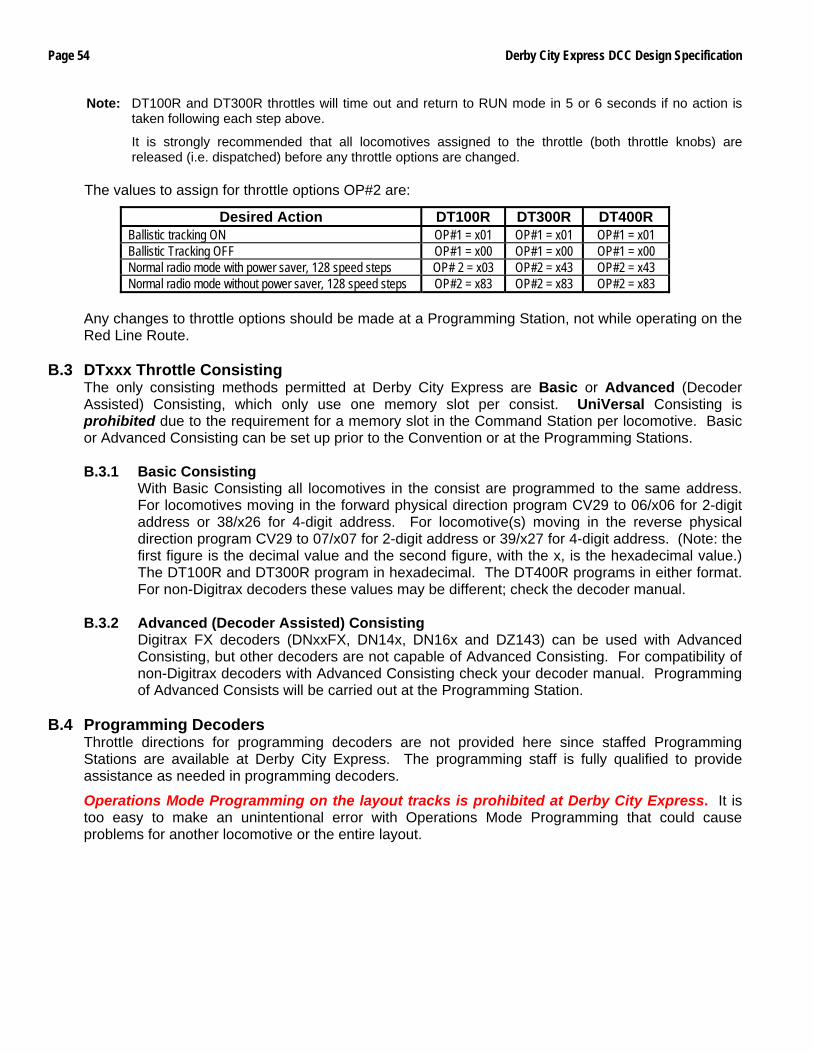
Page 54 Derby City Express DCC Design Specification
Note: DT100R and DT300R throttles will time out and return to RUN mode in 5 or 6 seconds if no action is taken following each step above.
It is strongly recommended that all locomotives assigned to the throttle (both throttle knobs) are released (i.e. dispatched) before any throttle options are changed.
The values to assign for throttle options OP#2 are:
Desired Action DT100R DT300R DT400R Ballistic tracking ON OP#1 = x01 OP#1 = x01 OP#1 = x01 Ballistic Tracking OFF OP#1 = x00 OP#1 = x00 OP#1 = x00 Normal radio mode with power saver, 128 speed steps OP# 2 = x03 OP#2 = x43 OP#2 = x43 Normal radio mode without power saver, 128 speed steps OP#2 = x83 OP#2 = x83 OP#2 = x83
Any changes to throttle options should be made at a Programming Station, not while operating on the Red Line Route.
B.3 DTxxx Throttle Consisting
The only consisting methods permitted at Derby City Express are Basic or Advanced (Decoder Assisted) Consisting, which only use one memory slot per consist. UniVersal Consisting is prohibited due to the requirement for a memory slot in the Command Station per locomotive. Basic or Advanced Consisting can be set up prior to the Convention or at the Programming Stations.
B.3.1 Basic Consisting
With Basic Consisting all locomotives in the consist are programmed to the same address. For locomotives moving in the forward physical direction program CV29 to 06/x06 for 2-digit address or 38/x26 for 4-digit address. For locomotive(s) moving in the reverse physical direction program CV29 to 07/x07 for 2-digit address or 39/x27 for 4-digit address. (Note: the first figure is the decimal value and the second figure, with the x, is the hexadecimal value.) The DT100R and DT300R program in hexadecimal. The DT400R programs in either format. For non-Digitrax decoders these values may be different; check the decoder manual.
B.3.2 Advanced (Decoder Assisted) Consisting
Digitrax FX decoders (DNxxFX, DN14x, DN16x and DZ143) can be used with Advanced Consisting, but other decoders are not capable of Advanced Consisting. For compatibility of non-Digitrax decoders with Advanced Consisting check your decoder manual. Programming of Advanced Consists will be carried out at the Programming Station.
B.4 Programming Decoders
Throttle directions for programming decoders are not provided here since staffed Programming Stations are available at Derby City Express. The programming staff is fully qualified to provide assistance as needed in programming decoders.
Operations Mode Programming on the layout tracks is prohibited at Derby City Express. It is too easy to make an unintentional error with Operations Mode Programming that could cause problems for another locomotive or the entire layout.
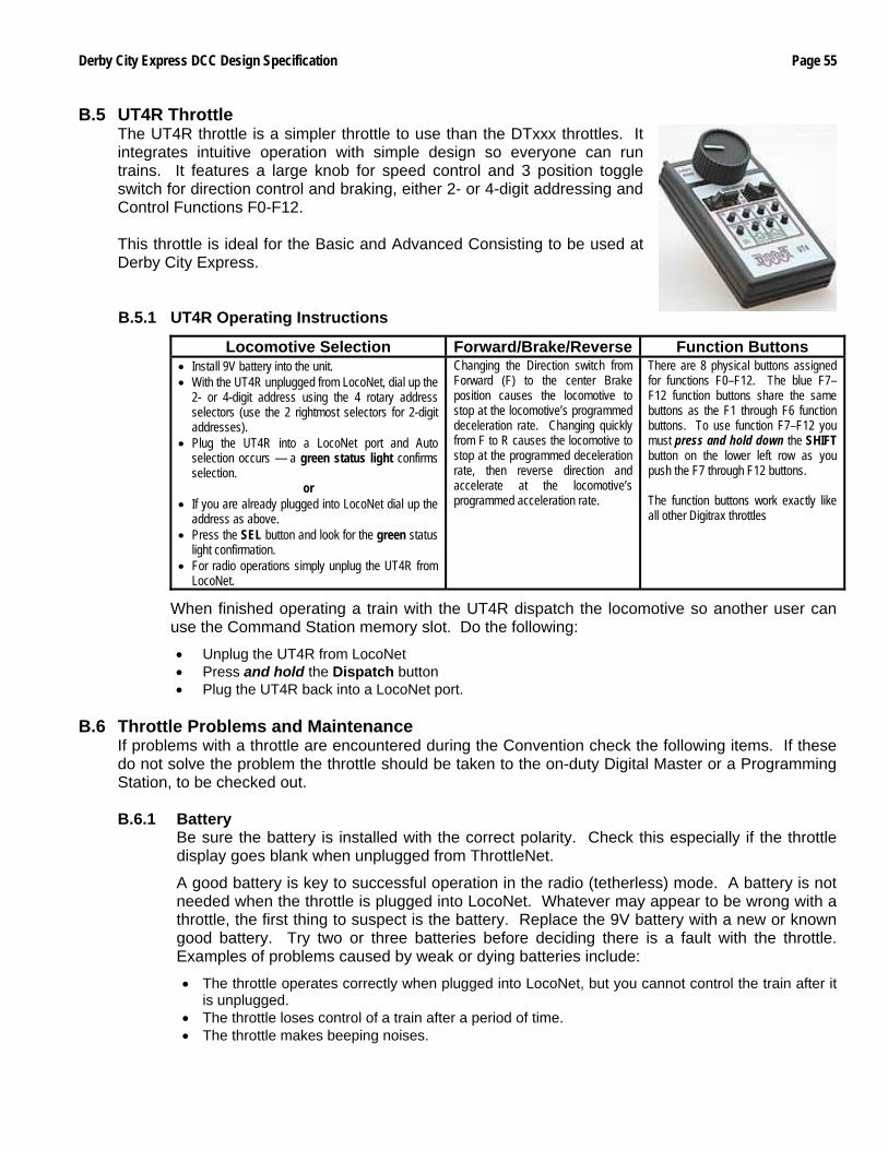
Derby City Express DCC Design Specification Page 55
B.5 UT4R Throttle The UT4R throttle is a simpler throttle to use than the DTxxx throttles. It integrates intuitive operation with simple design so everyone can run trains. It features a large knob for speed control and 3 position toggle switch for direction control and braking, either 2- or 4-digit addressing and Control Functions F0-F12. This throttle is ideal for the Basic and Advanced Consisting to be used at Derby City Express. B.5.1 UT4R Operating Instructions
Locomotive Selection Forward/Brake/Reverse Function Buttons • Install 9V battery into the unit. • With the UT4R unplugged from LocoNet, dial up the
2- or 4-digit address using the 4 rotary address selectors (use the 2 rightmost selectors for 2-digit addresses).
• Plug the UT4R into a LocoNet port and Auto selection occurs — a green status light confirms selection.
or • If you are already plugged into LocoNet dial up the
address as above. • Press the SEL button and look for the green status
light confirmation. • For radio operations simply unplug the UT4R from
LocoNet.
Changing the Direction switch from Forward (F) to the center Brake position causes the locomotive to stop at the locomotive’s programmed deceleration rate. Changing quickly from F to R causes the locomotive to stop at the programmed deceleration rate, then reverse direction and accelerate at the locomotive’s programmed acceleration rate.
There are 8 physical buttons assigned for functions F0–F12. The blue F7–F12 function buttons share the same buttons as the F1 through F6 function buttons. To use function F7–F12 you must press and hold down the SHIFT button on the lower left row as you push the F7 through F12 buttons. The function buttons work exactly like all other Digitrax throttles
When finished operating a train with the UT4R dispatch the locomotive so another user can use the Command Station memory slot. Do the following:
• Unplug the UT4R from LocoNet • Press and hold the Dispatch button • Plug the UT4R back into a LocoNet port.
B.6 Throttle Problems and Maintenance
If problems with a throttle are encountered during the Convention check the following items. If these do not solve the problem the throttle should be taken to the on-duty Digital Master or a Programming Station, to be checked out.
B.6.1 Battery
Be sure the battery is installed with the correct polarity. Check this especially if the throttle display goes blank when unplugged from ThrottleNet.
A good battery is key to successful operation in the radio (tetherless) mode. A battery is not needed when the throttle is plugged into LocoNet. Whatever may appear to be wrong with a throttle, the first thing to suspect is the battery. Replace the 9V battery with a new or known good battery. Try two or three batteries before deciding there is a fault with the throttle. Examples of problems caused by weak or dying batteries include:
• The throttle operates correctly when plugged into LocoNet, but you cannot control the train after it is unplugged.
• The throttle loses control of a train after a period of time. • The throttle makes beeping noises.
Page 56 Derby City Express DCC Design Specification
Don't assume that a newly purchased battery will always be a good battery. A new battery can have a high internal resistance that prevents it from putting out sufficient voltage and/or current to operate the throttle. Always purchase batteries from a store that sells lots of batteries and therefore always has fresh batteries on hand. Batteries have a "shelf life" as they will deteriorate even if not used.
B.6.2 No Radio Operation
If the throttle operates correctly when connected to LocoNet but not when untethered, even after ensuring the battery is good, the problem may be that radio transmission has been turned off. Bring the throttle to the on-duty Digital Master or a Programming Station to be checked out and make sure radio transmission is turned on.
B.6.3 Loose Throttle Knobs
The throttle knobs are held in place by two 0.050" screws, which can work loose over time. The screws require a 0.050" Allen wrench to tighten them. When tightening the screws, be careful not to put too much sideways pressure on the knob, as the encoder shaft can be damaged. If the throttle knob(s) gets loose bring the throttle to the on-duty Digital Master, who will have the required Allen wrench.
B.6.4 RJ12 Plug
There are 3 potential problems relating to the RJ12 plug on the end of the stubby LocoNet cable:
• The locking tab breaks off, • The contacts on the plug are bent or otherwise damaged (rare), or • The wires are not making a good connection with the contacts in the plug.
The solution to any of these problems is to replace the RJ12 plug. The on-duty Digital Master is equipped to replace your damaged RJ connector.
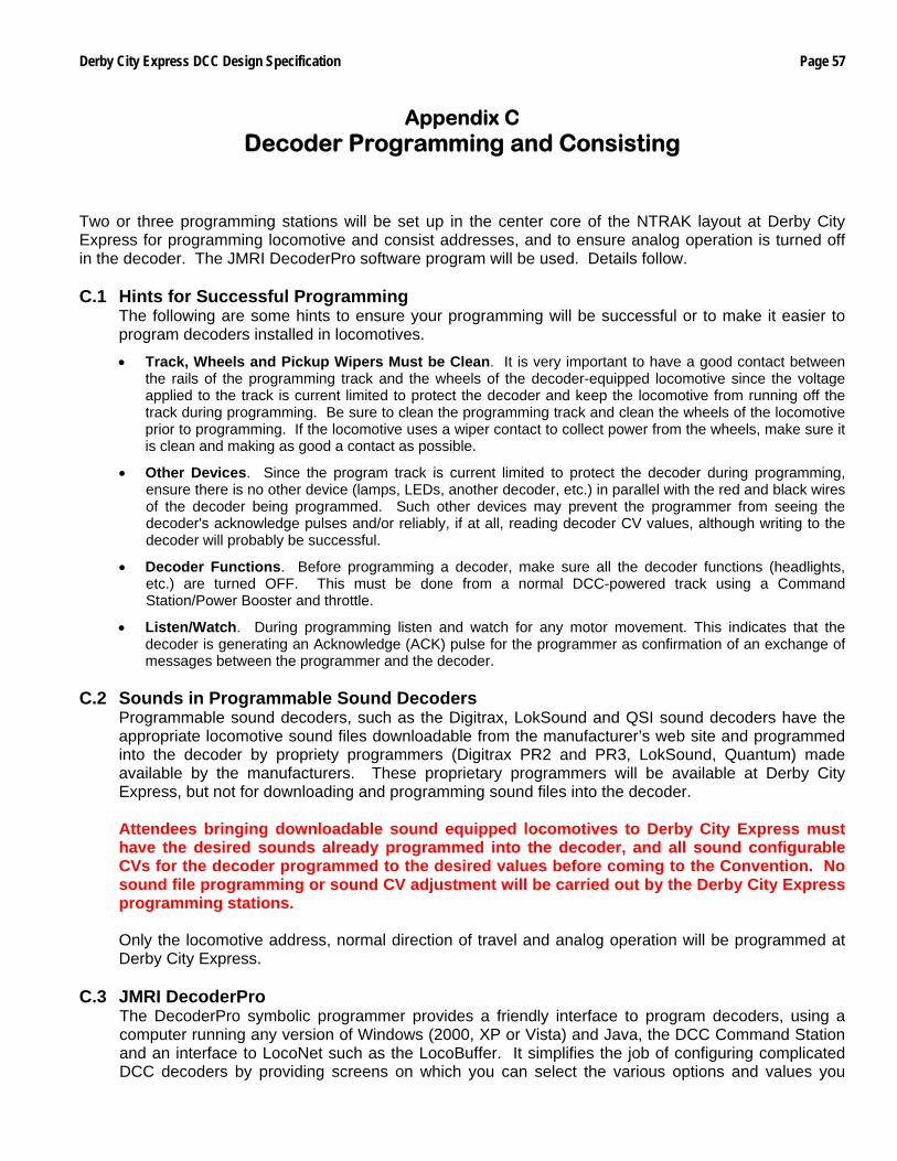
Derby City Express DCC Design Specification Page 57
Appendix C Decoder Programming and Consisting
Two or three programming stations will be set up in the center core of the NTRAK layout at Derby City Express for programming locomotive and consist addresses, and to ensure analog operation is turned off in the decoder. The JMRI DecoderPro software program will be used. Details follow. C.1 Hints for Successful Programming
The following are some hints to ensure your programming will be successful or to make it easier to program decoders installed in locomotives.
• Track, Wheels and Pickup Wipers Must be Clean. It is very important to have a good contact between the rails of the programming track and the wheels of the decoder-equipped locomotive since the voltage applied to the track is current limited to protect the decoder and keep the locomotive from running off the track during programming. Be sure to clean the programming track and clean the wheels of the locomotive prior to programming. If the locomotive uses a wiper contact to collect power from the wheels, make sure it is clean and making as good a contact as possible.
• Other Devices. Since the program track is current limited to protect the decoder during programming, ensure there is no other device (lamps, LEDs, another decoder, etc.) in parallel with the red and black wires of the decoder being programmed. Such other devices may prevent the programmer from seeing the decoder's acknowledge pulses and/or reliably, if at all, reading decoder CV values, although writing to the decoder will probably be successful.
• Decoder Functions. Before programming a decoder, make sure all the decoder functions (headlights, etc.) are turned OFF. This must be done from a normal DCC-powered track using a Command Station/Power Booster and throttle.
• Listen/Watch. During programming listen and watch for any motor movement. This indicates that the decoder is generating an Acknowledge (ACK) pulse for the programmer as confirmation of an exchange of messages between the programmer and the decoder.
C.2 Sounds in Programmable Sound Decoders
Programmable sound decoders, such as the Digitrax, LokSound and QSI sound decoders have the appropriate locomotive sound files downloadable from the manufacturer’s web site and programmed into the decoder by propriety programmers (Digitrax PR2 and PR3, LokSound, Quantum) made available by the manufacturers. These proprietary programmers will be available at Derby City Express, but not for downloading and programming sound files into the decoder. Attendees bringing downloadable sound equipped locomotives to Derby City Express must have the desired sounds already programmed into the decoder, and all sound configurable CVs for the decoder programmed to the desired values before coming to the Convention. No sound file programming or sound CV adjustment will be carried out by the Derby City Express programming stations. Only the locomotive address, normal direction of travel and analog operation will be programmed at Derby City Express.
C.3 JMRI DecoderPro The DecoderPro symbolic programmer provides a friendly interface to program decoders, using a computer running any version of Windows (2000, XP or Vista) and Java, the DCC Command Station and an interface to LocoNet such as the LocoBuffer. It simplifies the job of configuring complicated DCC decoders by providing screens on which you can select the various options and values you
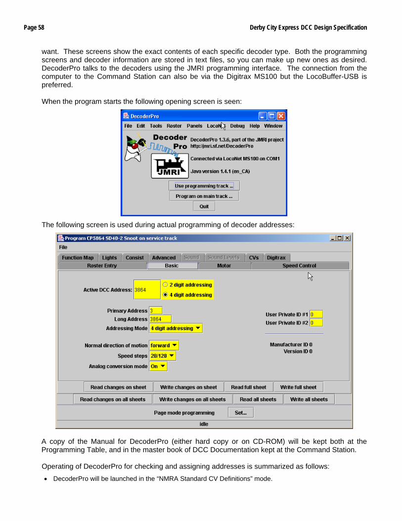
Page 58 Derby City Express DCC Design Specification
want. These screens show the exact contents of each specific decoder type. Both the programming screens and decoder information are stored in text files, so you can make up new ones as desired. DecoderPro talks to the decoders using the JMRI programming interface. The connection from the computer to the Command Station can also be via the Digitrax MS100 but the LocoBuffer-USB is preferred. When the program starts the following opening screen is seen:
The following screen is used during actual programming of decoder addresses:
A copy of the Manual for DecoderPro (either hard copy or on CD-ROM) will be kept both at the Programming Table, and in the master book of DCC Documentation kept at the Command Station. Operating of DecoderPro for checking and assigning addresses is summarized as follows:
• DecoderPro will be launched in the “NMRA Standard CV Definitions” mode.
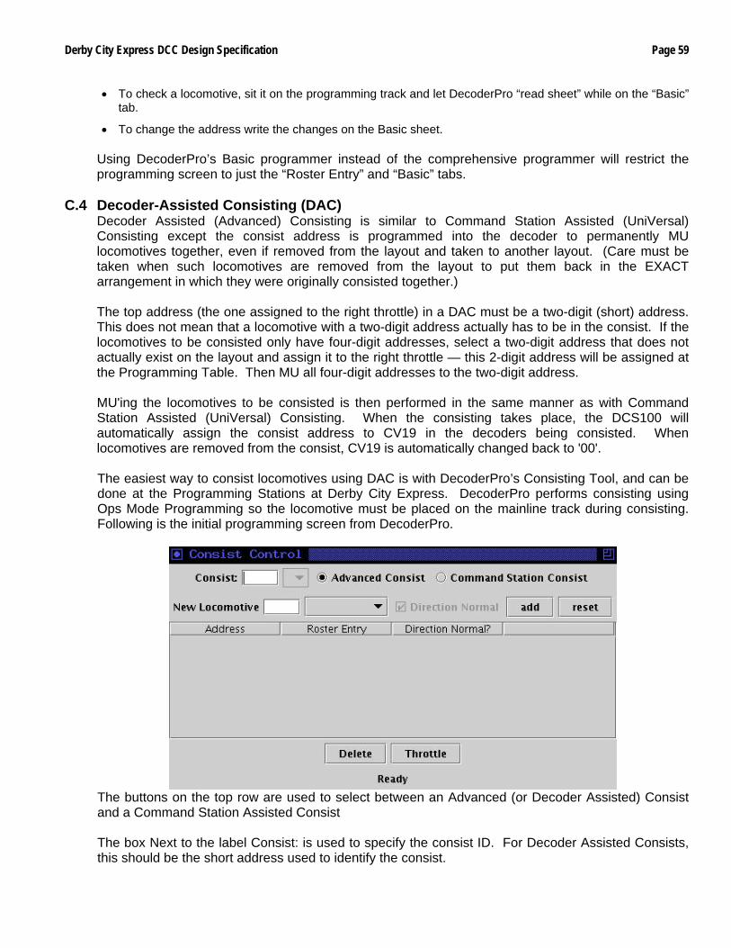
Derby City Express DCC Design Specification Page 59
• To check a locomotive, sit it on the programming track and let DecoderPro “read sheet” while on the “Basic” tab.
• To change the address write the changes on the Basic sheet. Using DecoderPro’s Basic programmer instead of the comprehensive programmer will restrict the programming screen to just the “Roster Entry” and “Basic” tabs.
C.4 Decoder-Assisted Consisting (DAC)
Decoder Assisted (Advanced) Consisting is similar to Command Station Assisted (UniVersal) Consisting except the consist address is programmed into the decoder to permanently MU locomotives together, even if removed from the layout and taken to another layout. (Care must be taken when such locomotives are removed from the layout to put them back in the EXACT arrangement in which they were originally consisted together.) The top address (the one assigned to the right throttle) in a DAC must be a two-digit (short) address. This does not mean that a locomotive with a two-digit address actually has to be in the consist. If the locomotives to be consisted only have four-digit addresses, select a two-digit address that does not actually exist on the layout and assign it to the right throttle — this 2-digit address will be assigned at the Programming Table. Then MU all four-digit addresses to the two-digit address. MU'ing the locomotives to be consisted is then performed in the same manner as with Command Station Assisted (UniVersal) Consisting. When the consisting takes place, the DCS100 will automatically assign the consist address to CV19 in the decoders being consisted. When locomotives are removed from the consist, CV19 is automatically changed back to '00'. The easiest way to consist locomotives using DAC is with DecoderPro’s Consisting Tool, and can be done at the Programming Stations at Derby City Express. DecoderPro performs consisting using Ops Mode Programming so the locomotive must be placed on the mainline track during consisting. Following is the initial programming screen from DecoderPro.
The buttons on the top row are used to select between an Advanced (or Decoder Assisted) Consist and a Command Station Assisted Consist The box Next to the label Consist: is used to specify the consist ID. For Decoder Assisted Consists, this should be the short address used to identify the consist.
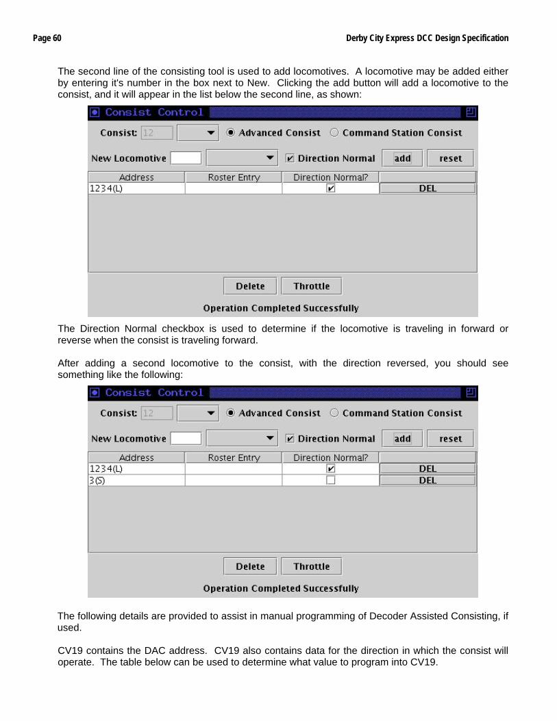
Page 60 Derby City Express DCC Design Specification
The second line of the consisting tool is used to add locomotives. A locomotive may be added either by entering it's number in the box next to New. Clicking the add button will add a locomotive to the consist, and it will appear in the list below the second line, as shown:
The Direction Normal checkbox is used to determine if the locomotive is traveling in forward or reverse when the consist is traveling forward. After adding a second locomotive to the consist, with the direction reversed, you should see something like the following:
The following details are provided to assist in manual programming of Decoder Assisted Consisting, if used. CV19 contains the DAC address. CV19 also contains data for the direction in which the consist will operate. The table below can be used to determine what value to program into CV19.
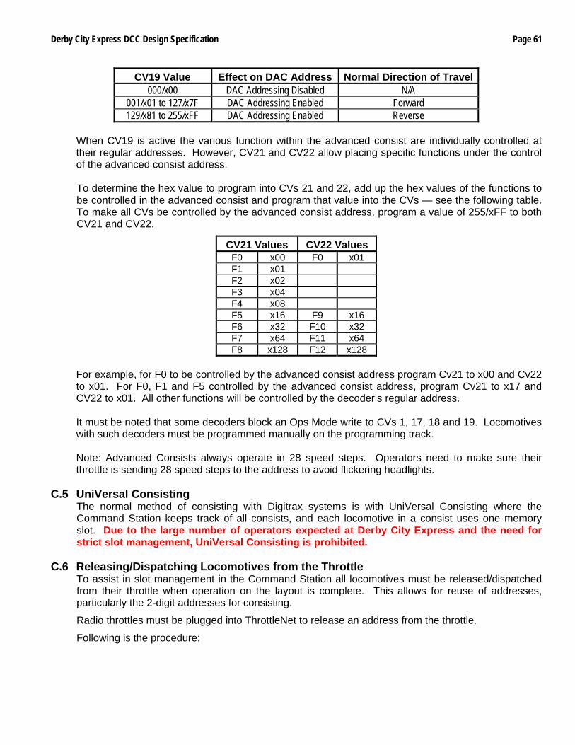
Derby City Express DCC Design Specification Page 61
CV19 Value Effect on DAC Address Normal Direction of Travel000/x00 DAC Addressing Disabled N/A
001/x01 to 127/x7F DAC Addressing Enabled Forward 129/x81 to 255/xFF DAC Addressing Enabled Reverse
When CV19 is active the various function within the advanced consist are individually controlled at their regular addresses. However, CV21 and CV22 allow placing specific functions under the control of the advanced consist address. To determine the hex value to program into CVs 21 and 22, add up the hex values of the functions to be controlled in the advanced consist and program that value into the CVs — see the following table. To make all CVs be controlled by the advanced consist address, program a value of 255/xFF to both CV21 and CV22.
CV21 Values CV22 Values F0 x00 F0 x01 F1 x01 F2 x02 F3 x04 F4 x08 F5 x16 F9 x16 F6 x32 F10 x32 F7 x64 F11 x64 F8 x128 F12 x128
For example, for F0 to be controlled by the advanced consist address program Cv21 to x00 and Cv22 to x01. For F0, F1 and F5 controlled by the advanced consist address, program Cv21 to x17 and CV22 to x01. All other functions will be controlled by the decoder’s regular address. It must be noted that some decoders block an Ops Mode write to CVs 1, 17, 18 and 19. Locomotives with such decoders must be programmed manually on the programming track. Note: Advanced Consists always operate in 28 speed steps. Operators need to make sure their throttle is sending 28 speed steps to the address to avoid flickering headlights.
C.5 UniVersal Consisting The normal method of consisting with Digitrax systems is with UniVersal Consisting where the Command Station keeps track of all consists, and each locomotive in a consist uses one memory slot. Due to the large number of operators expected at Derby City Express and the need for strict slot management, UniVersal Consisting is prohibited.
C.6 Releasing/Dispatching Locomotives from the Throttle To assist in slot management in the Command Station all locomotives must be released/dispatched from their throttle when operation on the layout is complete. This allows for reuse of addresses, particularly the 2-digit addresses for consisting.
Radio throttles must be plugged into ThrottleNet to release an address from the throttle.
Following is the procedure:
Page 62 Derby City Express DCC Design Specification
Releasing an Address from a Throttle DT100R Throttles DT300R Throttles DT400R Throttles
1. Plug the throttle into LocoNet. 2. Ensure the locomotive speed is 00. 3. Press SEL/SET key then MODE/DISP key.
DT100 LCD will show SEL.
1. Plug the throttle into LocoNet. 2. Ensure the locomotive speed is 00. 3. Press SEL key then press MODE key. The
DT300 LCD will show SEL.
1. Plug the throttle into LocoNet. 2. Ensure the locomotive speed is 00. 3. Press LOCO key then press DISP key. The
DT400 LCD will show SEL.
To release the address from a UT4R throttle do the following:
• Unplug the UT4R from LocoNet • Press and hold the Dispatch button • Plug the UT4R back into a LocoNet port.
C.7 Throttle Emergency Stop Setting
At the time of checking and programming decoder addresses and consist, operator throttles will be checked and set to ensure they are set for Local Emergency Stop (which is the default setting) rather than Global Emergency Stop. This is done to prevent the accidental stoppage of all DCC trains on the layout due to an operator inadvertently (or on purpose) pressing the Emergency Stop button on the throttle. Throttles used by the Digital Staff will be exempt from this requirement. The correct throttle options for DCC train operators at Derby City Express are:
Option Setting Meaning X00 Ballistic Tracking Off, Typematic Keys, Key and Knob Clicks, Local Run/Stop #1 x01 Ballistic Tracking & Typematic Keys, Key and Knob Clicks, Local Run/Stop x23 DT100R — 128 step decoder, Radio only + Power Saver enabled x43 DT300R/DT400R — 128 step decoder, Radio only + Power Saver enabled
#2
X83 All — 128 step decoder, Radio, Power Saver Mode off
Following is the procedure to set throttle options.
Procedure to Set Throttle Options DT100R Throttles DT300R Throttles DT400R Throttles
6. Unplug the DT100R from LocoNet. Press/hold SEL/SET key while plugging DT100R back into LocoNet. The display will show “oP:0x”., where “x” is the current setting.
7. Use R or L throttle knob to change setting to “oP:01”.
8. Press SEL/SET key to save setting and advance to next option. The display will show “oS:xx”.
9. Use R or L throttle knobs to change the setting to “oS:23”.
10. Press SEL/SET to save setting then press SEL/SET two more times to complete the process.
7. Unplug the DT300R from LocoNet. Press/hold SEL key while plugging DT300R back into LocoNet. The display will show OP#1=??? where ??? is current setting.
8. Use R or L throttle knob to change setting to x01.
9. Press SEL key to set OP#1 and advance to OP#2.
10. Use R or L throttle knob to change the setting to x43.
11. Press SEL key to set OP#2 and advance to OP#3.
12. Since no change required in OP#3–6 press SEL four more times to step through these options.
7. Press the OPTN t key. The right side of the display will show the current value for OP#1
8. Use R or L throttle knob to change the setting to x01.
9. Press ENTER key to set OP#1 to the selected value &advance to OP#2.
10. Use R or L throttle knob to change the setting to x43.
11. Press ENTER key to set OP#2 to the selected value and advance to OP#3.
12. Since no change is required in OP#3–6 press ENTER key four more times to step through these options.
Note: DT100R and DT300R throttles will time out and return to RUN mode in 5 or 6 seconds if no action is taken following each step above.
It is strongly recommended that all locomotives assigned to the throttle (both throttle knobs) are released (i.e. dispatched) before any throttle options are changed.
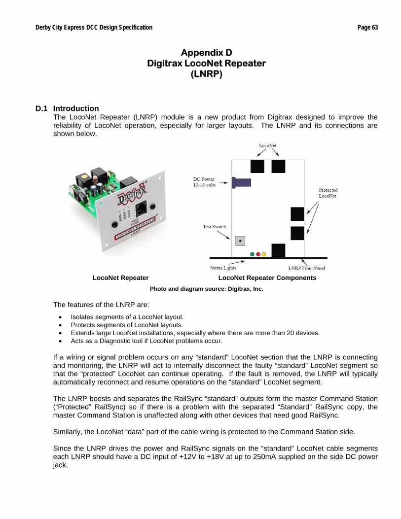
Derby City Express DCC Design Specification Page 63
Appendix D Digitrax LocoNet Repeater
(LNRP) D.1 Introduction
The LocoNet Repeater (LNRP) module is a new product from Digitrax designed to improve the reliability of LocoNet operation, especially for larger layouts. The LNRP and its connections are shown below.
LocoNet Repeater LocoNet Repeater Components Photo and diagram source: Digitrax, Inc.
The features of the LNRP are:
• Isolates segments of a LocoNet layout. • Protects segments of LocoNet layouts. • Extends large LocoNet installations, especially where there are more than 20 devices. • Acts as a Diagnostic tool if LocoNet problems occur.
If a wiring or signal problem occurs on any “standard” LocoNet section that the LNRP is connecting and monitoring, the LNRP will act to internally disconnect the faulty “standard” LocoNet segment so that the “protected” LocoNet can continue operating. If the fault is removed, the LNRP will typically automatically reconnect and resume operations on the “standard” LocoNet segment. The LNRP boosts and separates the RailSync “standard” outputs form the master Command Station (“Protected” RailSync) so if there is a problem with the separated “Standard” RailSync copy, the master Command Station is unaffected along with other devices that need good RailSync. Similarly, the LocoNet “data” part of the cable wiring is protected to the Command Station side. Since the LNRP drives the power and RailSync signals on the “standard” LocoNet cable segments each LNRP should have a DC input of +12V to +18V at up to 250mA supplied on the side DC power jack.
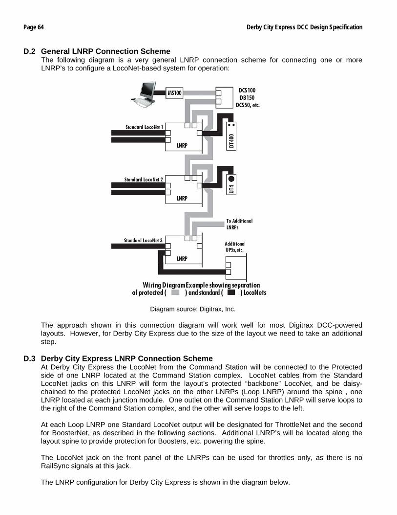
Page 64 Derby City Express DCC Design Specification
D.2 General LNRP Connection Scheme The following diagram is a very general LNRP connection scheme for connecting one or more LNRP’s to configure a LocoNet-based system for operation:
Diagram source: Digitrax, Inc.
The approach shown in this connection diagram will work well for most Digitrax DCC-powered layouts. However, for Derby City Express due to the size of the layout we need to take an additional step.
D.3 Derby City Express LNRP Connection Scheme At Derby City Express the LocoNet from the Command Station will be connected to the Protected side of one LNRP located at the Command Station complex. LocoNet cables from the Standard LocoNet jacks on this LNRP will form the layout’s protected “backbone” LocoNet, and be daisy-chained to the protected LocoNet jacks on the other LNRPs (Loop LNRP) around the spine , one LNRP located at each junction module. One outlet on the Command Station LNRP will serve loops to the right of the Command Station complex, and the other will serve loops to the left. At each Loop LNRP one Standard LocoNet output will be designated for ThrottleNet and the second for BoosterNet, as described in the following sections. Additional LNRP’s will be located along the layout spine to provide protection for Boosters, etc. powering the spine. The LocoNet jack on the front panel of the LNRPs can be used for throttles only, as there is no RailSync signals at this jack. The LNRP configuration for Derby City Express is shown in the diagram below.
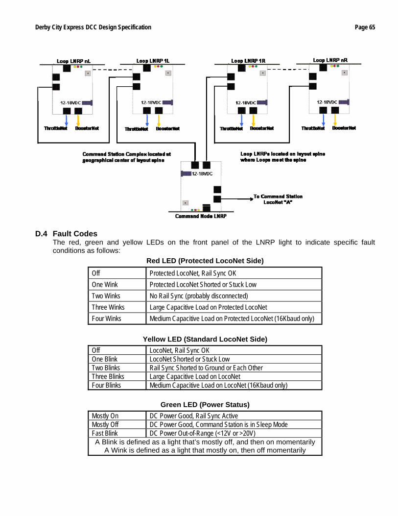
Derby City Express DCC Design Specification Page 65
D.4 Fault Codes
The red, green and yellow LEDs on the front panel of the LNRP light to indicate specific fault conditions as follows:
Red LED (Protected LocoNet Side)
Off Protected LocoNet, Rail Sync OK One Wink Protected LocoNet Shorted or Stuck Low Two Winks No Rail Sync (probably disconnected) Three Winks Large Capacitive Load on Protected LocoNet Four Winks Medium Capacitive Load on Protected LocoNet (16Kbaud only)
Yellow LED (Standard LocoNet Side)
Off LocoNet, Rail Sync OK One Blink LocoNet Shorted or Stuck Low Two Blinks Rail Sync Shorted to Ground or Each Other Three Blinks Large Capacitive Load on LocoNet Four Blinks Medium Capacitive Load on LocoNet (16Kbaud only)
Green LED (Power Status) Mostly On DC Power Good, Rail Sync Active Mostly Off DC Power Good, Command Station is in Sleep Mode Fast Blink DC Power Out-of-Range (<12V or >20V) A Blink is defined as a light that’s mostly off, and then on momentarily
A Wink is defined as a light that mostly on, then off momentarily

Page 66 Derby City Express DCC Design Specification
Derby City Express DCC Design Specification Page 67
Appendix E Module Inspection
Since the same problems with modules and larger layouts that cause bottlenecks and train backups appear to surface year after year, all modules destined for the NTRAK layout at Derby City Express must meet the NTRAK Mechanical and Electrical Specifications, as a minimum. It will be the responsibility of Clubs with recognized Certification procedures to inspect and certify the modules their Members are bringing to Derby City Express. Modules pre-certified will have a Certification Sticker applied before coming to Derby City Express. Modules without the Certification Sticker will receive a cursory visual inspection on arrival, and before they are assembled into the layout. Any deficiencies found will be documented for a more detailed inspection once the problem(s) is remedied by the owner and installed in the layout, but before operations begin. If the module clearly does not meet basic NTRAK, Bend Track, TwinTrak or oNeTRAK standards it may be relegated to a branch section off the main layout depending on the inspectors’ recommendation. The objective of certification and inspection of modules is to increase reliability of the entire layout and improve enjoyment for spectators and crews alike. E.1 Pre-Certification Inspection
Clubs with recognized Certification procedures should carry out the following checks on all modules that will be in the Derby City Express NTRAK layout: E.1.1 Track Inspection
Any shortcomings found should be correct prior to applying the certification sticker.
Inspection Train — Run a short inspection train with the following consist:
• 2 or more long 6-axle locomotives (SD90) coupled together with body-mounted couplers • a PA-1 locomotive (long 6-axle wheelbase truck) • several long (86’) cars coupled together
Ensure these locomotives and cars track easily without derailing around all 18” (blue) and 24” curves, reverse curves and crossovers. Pay particular attention to “S” curves that need at least an 8” straight section between the curves for a smooth transition. Car Clearance — Include in the inspection train an 86’ “clearance car” with a profile form 1.75” above the rail to test clearances to NTRAK standards as well as to clear all possible double stack loads. The profile form should also have appropriate side profiles to simulate the wide low pressure cylinders on a Y6b articulated locomotive. Flange Clearance — Include in the inspection train some cars with Micro-Trains standard (pizza cutter) wheels and some with Micro-Trains lo-profile wheels. Watch for cars bouncing that may indicate track out of gauge, ballast on the track or in flangeways, attempts to pick turnouts or that derail. Turnouts — Check that crossovers between Red–Yellow–Blue are Peco long turnouts. Check that all turnouts have positive operating controls. Repair, replace or spike turnouts as necessary. Restrictions on long locomotive and cars may be needed where the curved part of medium or short turnouts are used, particularly in crossovers.
Page 68 Derby City Express DCC Design Specification
Track — All track must be Code 80 at the ends of the module. Sections of Micro-Engineering or Peco Code 55 track are acceptable, but Atlas Code 55 is prohibited due to interference of the spikes with wheels. There should be no damaged or kinky rails. Track Alignment — Ensure the rails at the end of modules are level and not bent up due to warped roadbed or plywood. Ensure the module ends are flat and square with no overhanging plywood top. Check that track spacing is 1.5” ± 1/16”.
E.1.2 Electrical Inspection
Any shortcomings found should be correct prior to applying the certification sticker.
Continuity — To check track continuity quickly operate a singe 4-axle diesel locomotive without a flywheel along all tracks and crossovers, and check for dead sections in turnouts and connector tracks, and dirty track. This locomotive should run slowly over turnouts and suspect areas. Wire Size — Ensure all Red-Yellow-Blue-Green bus wires meet the NTRAK electrical standards if the module is equipped with Cinch-Jones connectors or meet the NTRAK Recommended Practice if the module is equipped with Powerpole Connectors, from the connector at one end of the module to the connector at the other end of the module. Ensure the presence of the White Wire and that it is 16 gauge or heavier. Ensure 120VAC connections on the module meet the specifications of the NTRAK Recommended Practice on 120VAC Wiring; any power strip present must be rated for 15A minimum and be easily removable. Junctions and Inside Corners — Check that all wiring and connectors are properly reversed where required. Improper plug wiring can damage train controls. Yard Controls — Ensure the train controls in yards have the capability to disconnect from the power of the Red-Yellow-Blue community tracks. Isolation of Rails — Ensure all connectors and rails are isolated from all other rails; this can be checked using an ohmmeter. Cinch Jones Connectors — Ensure all Cinch Jones connectors are properly color-coded and the contacts are clean. To clean apply Conducta-Lube or CRC Contact Cleaner to the contacts and push plugs in and out several times. Powerpole Connectors — Endure all Powerpole Connectors are properly color-coded and the contacts are clean. Voltage Drop — Observe trains carefully to see if they slow in one or more areas on the module. Use a digital meter (RRampMeter) to measure voltage and check for loose connections by wiggling the Cinch Jones connectors and track feeder wires. Repair or replace as necessary. Test Under Load — For troubleshooting low voltage conditions use a RRampMeter with a No. 1156 automotive bulb connected to the output and a DCC input to the module. The No. 1156 draws 2.5A, which will allow determining accurate voltage, drop across a module. Target voltage drop per module is 0.1 volt or less.
Derby City Express DCC Design Specification Page 69
E.2 On Site Inspection Modules without a certification sticker will be tested on arrival at the Convention. Following are the items to be checked during this initial module inspection: • Check for bent or damaged rails of community tracks, especially at the module ends. Make note of any
damage for repair by owner.
• Modules with Cinch-Jones Connectors
• Check for proper wire size (#18 or larger) with the male Cinch-Jones plugs on the right end. Modules with telephone-type wiring will not be permitted in the layout, except for short rail feeders.
• Check for correct color-coding on the Cinch-Jones connectors. Apply correct colored tape where required.
• Check the connector pins on the Cinch-Jones plugs for cleanliness. Wire brush as necessary and apply Conducta-Lube or TV-Tuner Cleaner.
• If the module has chassis-mount female Cinch-Jones sockets check solder connections to them closely when moving wires around. Check for wear and looseness of the contact pins. If one or both feel loose add a tag and conduct a simple voltage drop test using a MRC 501 and a 10-ohm resistor. Replace socket or jump socket as necessary.
• Modules with Powerpole Connectors
• Check for proper track bus wire size (#12 gauge) with the correct orientation of the Powerpole connectors (red-over-black at the right end and black-over-red at the left end).
• Ensure all Powerpole connectors are properly color coded and the contacts are clean.
• Check that owners of modules or module sets employing Powerpole connectors have Powerpole to Conch-Jones adapters available per the NTRAK Recommended Practice to connect to adjacent Cinch-Jones modules if required.
• Check terminal blocks for loose or disconnected wires.
• Check for presence of the White line (if we decide to require it) and the 120VAC line.
An “OK” sticker will be applied to modules passing all the above items or notes made of defects on a 3” x 5” card for later follow-up.

Page 70 Derby City Express DCC Design Specification
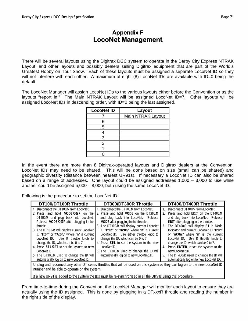
Derby City Express DCC Design Specification Page 71
Appendix F LocoNet Management
There will be several layouts using the Digitrax DCC system to operate in the Derby City Express NTRAK Layout, and other layouts and possibly dealers selling Digitrax equipment that are part of the World’s Greatest Hobby on Tour Show. Each of these layouts must be assigned a separate LocoNet ID so they will not interfere with each other. A maximum of eight (8) LocoNet IDs are available with ID=0 being the default. The LocoNet Manager will assign LocoNet IDs to the various layouts either before the Convention or as the layouts “report in.” The Main NTRAK Layout will be assigned LocoNet ID=7. Other layouts will be assigned LocoNet IDs in descending order, with ID=0 being the last assigned.
LocoNet ID Layout 7 Main NTRAK Layout 6 5 4 3 2 1 0
In the event there are more than 8 Digitrax-operated layouts and Digitrax dealers at the Convention, LocoNet IDs may need to be shared. This will be done based on size (small can be shared) and geographic diversity (distance between nearest UR91s). If necessary a LocoNet ID can also be shared based on a range of addresses. One layout could be assigned addresses 1,000 – 3,000 to use while another could be assigned 5,000 – 8,000, both using the same LocoNet ID. Following is the procedure to set the LocoNet ID:
DT100/DT100R Throttle DT300/DT300R Throttle DT400/DT400R Throttle 1. Disconnect the DT100/R from LocoNet. 2. Press and hold MODE/DISP on the
DT100/R and plug back into LocoNet. Release MODE/DISP after plugging in the throttle.
3. The DT100/R will display current LocoNet ID “Ir:0n” or “rA:0n,” where “n” is current LocoNet ID. Use R throttle knob to change the ID, which can be 0 to 7.
4. Press SEL/SET to set the system to new LocoNet ID.
5. The DT100/R used to change the ID will automatically log on to new LocoNet ID.
1. Disconnect the DT300/R from LocoNet. 2. Press and hold MODE on the DT300/R
and plug back into LocoNet. Release MODE after plugging in the throttle.
3. The DT300/R will display current LocoNet ID “Ir:0n” or “rA:0n,” where “n” is current LocoNet ID. Use either throttle knob to change the ID, which can be 0 to 7.
4. Press SEL to set the system to the new LocoNet ID.
5. The DT300/R used to change the ID will automatically log on to new LocoNet ID.
1. Disconnect DT400/R from LocoNet. 2. Press and hold EDIT on the DT400/R
and plug back into LocoNet. Release EDIT after plugging in the throttle.
3. The DT400/R will display E1 in Mode Indicator and current LocoNet ID “Ir:0n” or “rA:0n,” where “n” is the current LocoNet ID. Use R throttle knob to change the ID, which can be 0 to 7.
4. Press ENTER to set the system to the new LocoNet ID.
5. The DT400/R used to change the ID will automatically log on to new LocoNet ID.
Unplug and reconnect any other DT series throttles that will be used on this system so they can log on to the new LocoNet ID number and be able to operate on the system.
If a new UR91 is added to the system the IDs must be re-synchronized in all the UR91s using this procedure. From time-to-time during the Convention, the LocoNet Manager will monitor each layout to ensure they are actually using the ID assigned. This is done by plugging in a DTxxxR throttle and reading the number in the right side of the display.

Page 72 Derby City Express DCC Design Specification
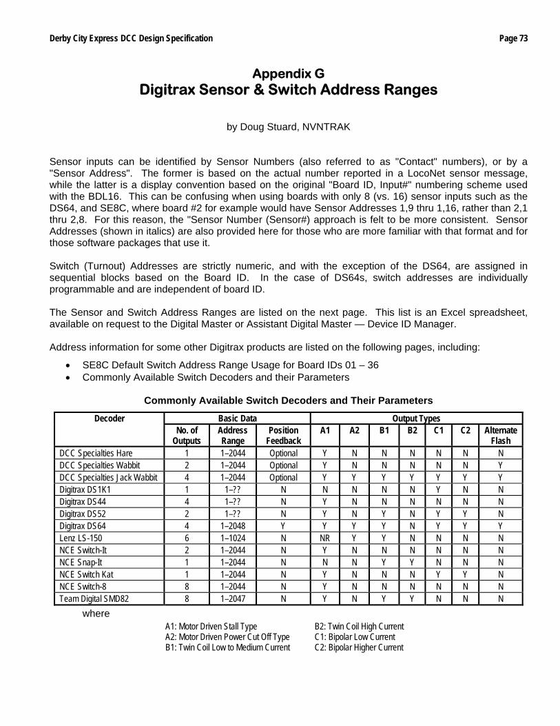
Derby City Express DCC Design Specification Page 73
Appendix G Digitrax Sensor & Switch Address Ranges
by Doug Stuard, NVNTRAK
Sensor inputs can be identified by Sensor Numbers (also referred to as "Contact" numbers), or by a "Sensor Address". The former is based on the actual number reported in a LocoNet sensor message, while the latter is a display convention based on the original "Board ID, Input#" numbering scheme used with the BDL16. This can be confusing when using boards with only 8 (vs. 16) sensor inputs such as the DS64, and SE8C, where board #2 for example would have Sensor Addresses 1,9 thru 1,16, rather than 2,1 thru 2,8. For this reason, the "Sensor Number (Sensor#) approach is felt to be more consistent. Sensor Addresses (shown in italics) are also provided here for those who are more familiar with that format and for those software packages that use it. Switch (Turnout) Addresses are strictly numeric, and with the exception of the DS64, are assigned in sequential blocks based on the Board ID. In the case of DS64s, switch addresses are individually programmable and are independent of board ID. The Sensor and Switch Address Ranges are listed on the next page. This list is an Excel spreadsheet, available on request to the Digital Master or Assistant Digital Master — Device ID Manager. Address information for some other Digitrax products are listed on the following pages, including:
• SE8C Default Switch Address Range Usage for Board IDs 01 – 36 • Commonly Available Switch Decoders and their Parameters
Commonly Available Switch Decoders and Their Parameters
Basic Data Output Types Decoder No. of
Outputs Address Range
Position Feedback
A1 A2 B1 B2 C1 C2 Alternate Flash
DCC Specialties Hare 1 1–2044 Optional Y N N N N N N DCC Specialties Wabbit 2 1–2044 Optional Y N N N N N Y DCC Specialties Jack Wabbit 4 1–2044 Optional Y Y Y Y Y Y Y Digitrax DS1K1 1 1–?? N N N N N Y N N Digitrax DS44 4 1–?? N Y N N N N N N Digitrax DS52 2 1–?? N Y N Y N Y Y N Digitrax DS64 4 1–2048 Y Y Y Y N Y Y Y Lenz LS-150 6 1–1024 N NR Y Y N N N N NCE Switch-It 2 1–2044 N Y N N N N N N NCE Snap-It 1 1–2044 N N N Y Y N N N NCE Switch Kat 1 1–2044 N Y N N N Y Y N NCE Switch-8 8 1–2044 N Y N N N N N N Team Digital SMD82 8 1–2047 N Y N Y Y N N N
where A1: Motor Driven Stall Type B2: Twin Coil High Current A2: Motor Driven Power Cut Off Type C1: Bipolar Low Current B1: Twin Coil Low to Medium Current C2: Bipolar Higher Current
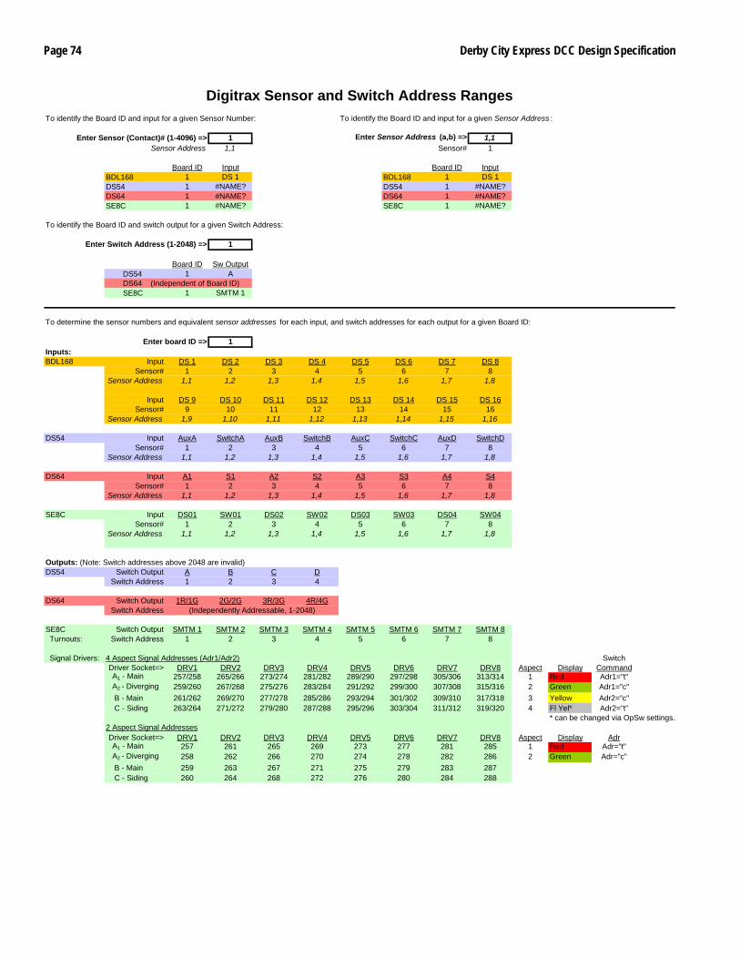
Page 74 Derby City Express DCC Design Specification
Digitrax Sensor and Switch Address Ranges To identify the Board ID and input for a given Sensor Number: To identify the Board ID and input for a given Sensor Address :
Enter Sensor (Contact)# (1-4096) => 1 Enter Sensor Address (a,b) => 1,1Sensor Address 1,1 Sensor# 1
Board ID Input Board ID InputBDL168 1 DS 1 BDL168 1 DS 1DS54 1 #NAME? DS54 1 #NAME?DS64 1 #NAME? DS64 1 #NAME?SE8C 1 #NAME? SE8C 1 #NAME?
To identify the Board ID and switch output for a given Switch Address:
Enter Switch Address (1-2048) => 1
Board ID Sw Output DS54 1 A DS64 (Independent of Board ID) SE8C 1 SMTM 1
To determine the sensor numbers and equivalent sensor addresses for each input, and switch addresses for each output for a given Board ID:
Enter board ID => 1Inputs:BDL168 Input DS 1 DS 2 DS 3 DS 4 DS 5 DS 6 DS 7 DS 8
Sensor# 1 2 3 4 5 6 7 8Sensor Address 1,1 1,2 1,3 1,4 1,5 1,6 1,7 1,8
Input DS 9 DS 10 DS 11 DS 12 DS 13 DS 14 DS 15 DS 16Sensor# 9 10 11 12 13 14 15 16
Sensor Address 1,9 1,10 1,11 1,12 1,13 1,14 1,15 1,16
DS54 Input AuxA SwitchA AuxB SwitchB AuxC SwitchC AuxD SwitchDSensor# 1 2 3 4 5 6 7 8
Sensor Address 1,1 1,2 1,3 1,4 1,5 1,6 1,7 1,8
DS64 Input A1 S1 A2 S2 A3 S3 A4 S4Sensor# 1 2 3 4 5 6 7 8
Sensor Address 1,1 1,2 1,3 1,4 1,5 1,6 1,7 1,8
SE8C Input DS01 SW01 DS02 SW02 DS03 SW03 DS04 SW04Sensor# 1 2 3 4 5 6 7 8
Sensor Address 1,1 1,2 1,3 1,4 1,5 1,6 1,7 1,8
Outputs: (Note: Switch addresses above 2048 are invalid)DS54 Switch Output A B C D
Switch Address 1 2 3 4
DS64 Switch Output 1R/1G 2G/2G 3R/3G 4R/4GSwitch Address
SE8C Switch Output SMTM 1 SMTM 2 SMTM 3 SMTM 4 SMTM 5 SMTM 6 SMTM 7 SMTM 8 Turnouts: Switch Address 1 2 3 4 5 6 7 8
Signal Drivers: 4 Aspect Signal Addresses (Adr1/Adr2) SwitchDriver Socket=> DRV1 DRV2 DRV3 DRV4 DRV5 DRV6 DRV7 DRV8 Aspect Display Command
A1 - Main 257/258 265/266 273/274 281/282 289/290 297/298 305/306 313/314 1 Red Adr1="t" A2 - Diverging 259/260 267/268 275/276 283/284 291/292 299/300 307/308 315/316 2 Green Adr1="c" B - Main 261/262 269/270 277/278 285/286 293/294 301/302 309/310 317/318 3 Yellow Adr2="c" C - Siding 263/264 271/272 279/280 287/288 295/296 303/304 311/312 319/320 4 Fl Yel* Adr2="t"
* can be changed via OpSw settings.2 Aspect Signal AddressesDriver Socket=> DRV1 DRV2 DRV3 DRV4 DRV5 DRV6 DRV7 DRV8 Aspect Display Adr
A1 - Main 257 261 265 269 273 277 281 285 1 Red Adr="t" A2 - Diverging 258 262 266 270 274 278 282 286 2 Green Adr="c" B - Main 259 263 267 271 275 279 283 287 C - Siding 260 264 268 272 276 280 284 288
(Independently Addressable, 1-2048)
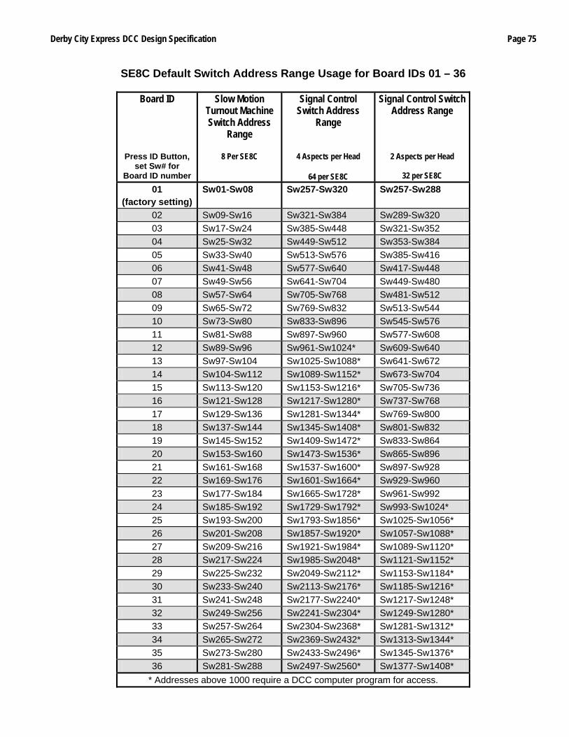
Derby City Express DCC Design Specification Page 75
SE8C Default Switch Address Range Usage for Board IDs 01 – 36
Board ID
Press ID Button, set Sw# for
Board ID number
Slow Motion Turnout Machine Switch Address
Range
8 Per SE8C
Signal Control Switch Address
Range
4 Aspects per Head
64 per SE8C
Signal Control Switch Address Range
2 Aspects per Head
32 per SE8C
01 (factory setting)
Sw01-Sw08 Sw257-Sw320 Sw257-Sw288
02 Sw09-Sw16 Sw321-Sw384 Sw289-Sw320 03 Sw17-Sw24 Sw385-Sw448 Sw321-Sw352 04 Sw25-Sw32 Sw449-Sw512 Sw353-Sw384 05 Sw33-Sw40 Sw513-Sw576 Sw385-Sw416 06 Sw41-Sw48 Sw577-Sw640 Sw417-Sw448 07 Sw49-Sw56 Sw641-Sw704 Sw449-Sw480 08 Sw57-Sw64 Sw705-Sw768 Sw481-Sw512 09 Sw65-Sw72 Sw769-Sw832 Sw513-Sw544 10 Sw73-Sw80 Sw833-Sw896 Sw545-Sw576 11 Sw81-Sw88 Sw897-Sw960 Sw577-Sw608 12 Sw89-Sw96 Sw961-Sw1024* Sw609-Sw640 13 Sw97-Sw104 Sw1025-Sw1088* Sw641-Sw672 14 Sw104-Sw112 Sw1089-Sw1152* Sw673-Sw704 15 Sw113-Sw120 Sw1153-Sw1216* Sw705-Sw736 16 Sw121-Sw128 Sw1217-Sw1280* Sw737-Sw768 17 Sw129-Sw136 Sw1281-Sw1344* Sw769-Sw800 18 Sw137-Sw144 Sw1345-Sw1408* Sw801-Sw832 19 Sw145-Sw152 Sw1409-Sw1472* Sw833-Sw864 20 Sw153-Sw160 Sw1473-Sw1536* Sw865-Sw896 21 Sw161-Sw168 Sw1537-Sw1600* Sw897-Sw928 22 Sw169-Sw176 Sw1601-Sw1664* Sw929-Sw960 23 Sw177-Sw184 Sw1665-Sw1728* Sw961-Sw992 24 Sw185-Sw192 Sw1729-Sw1792* Sw993-Sw1024* 25 Sw193-Sw200 Sw1793-Sw1856* Sw1025-Sw1056* 26 Sw201-Sw208 Sw1857-Sw1920* Sw1057-Sw1088* 27 Sw209-Sw216 Sw1921-Sw1984* Sw1089-Sw1120* 28 Sw217-Sw224 Sw1985-Sw2048* Sw1121-Sw1152* 29 Sw225-Sw232 Sw2049-Sw2112* Sw1153-Sw1184* 30 Sw233-Sw240 Sw2113-Sw2176* Sw1185-Sw1216* 31 Sw241-Sw248 Sw2177-Sw2240* Sw1217-Sw1248* 32 Sw249-Sw256 Sw2241-Sw2304* Sw1249-Sw1280* 33 Sw257-Sw264 Sw2304-Sw2368* Sw1281-Sw1312* 34 Sw265-Sw272 Sw2369-Sw2432* Sw1313-Sw1344* 35 Sw273-Sw280 Sw2433-Sw2496* Sw1345-Sw1376* 36 Sw281-Sw288 Sw2497-Sw2560* Sw1377-Sw1408*
* Addresses above 1000 require a DCC computer program for access.

Page 76 Derby City Express DCC Design Specification
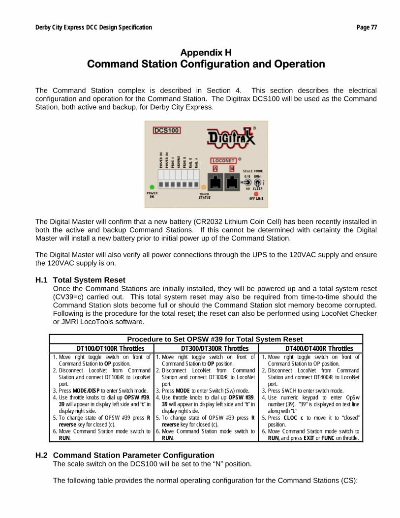
Derby City Express DCC Design Specification Page 77
Appendix H Command Station Configuration and Operation
The Command Station complex is described in Section 4. This section describes the electrical configuration and operation for the Command Station. The Digitrax DCS100 will be used as the Command Station, both active and backup, for Derby City Express.
The Digital Master will confirm that a new battery (CR2032 Lithium Coin Cell) has been recently installed in both the active and backup Command Stations. If this cannot be determined with certainty the Digital Master will install a new battery prior to initial power up of the Command Station. The Digital Master will also verify all power connections through the UPS to the 120VAC supply and ensure the 120VAC supply is on. H.1 Total System Reset
Once the Command Stations are initially installed, they will be powered up and a total system reset (CV39=c) carried out. This total system reset may also be required from time-to-time should the Command Station slots become full or should the Command Station slot memory become corrupted. Following is the procedure for the total reset; the reset can also be performed using LocoNet Checker or JMRI LocoTools software.
Procedure to Set OPSW #39 for Total System Reset DT100/DT100R Throttles DT300/DT300R Throttles DT400/DT400R Throttles
1. Move right toggle switch on front of Command Station to OP position.
2. Disconnect LocoNet from Command Station and connect DT100/R to LocoNet port.
3. Press MODE/DISP to enter Switch mode. 4. Use throttle knobs to dial up OPSW #39.
39 will appear in display left side and “t” in display right side.
5. To change state of OPSW #39 press R reverse key for closed (c).
6. Move Command Station mode switch to RUN.
1. Move right toggle switch on front of Command Station to OP position.
2. Disconnect LocoNet from Command Station and connect DT300/R to LocoNet port.
3. Press MODE to enter Switch (Sw) mode. 4. Use throttle knobs to dial up OPSW #39.
39 will appear in display left side and “t” in display right side.
5. To change state of OPSW #39 press R reverse key for closed (c).
6. Move Command Station mode switch to RUN.
1. Move right toggle switch on front of Command Station to OP position.
2. Disconnect LocoNet from Command Station and connect DT400/R to LocoNet port.
3. Press SWCH to enter switch mode. 4. Use numeric keypad to enter OpSw
number (39). “39” is displayed on text line along with “t.”
5. Press CLOC c to move it to “closed” position.
6. Move Command Station mode switch to RUN, and press EXIT or FUNC on throttle.
H.2 Command Station Parameter Configuration
The scale switch on the DCS100 will be set to the “N” position. The following table provides the normal operating configuration for the Command Stations (CS):
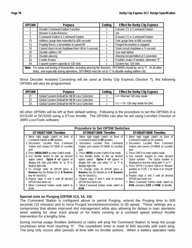
Page 78 Derby City Express DCC Design Specification
OPSW# Purpose Setting Effect for Derby City Express 2 Disable Command Station Function t Ensures CS is Command Station 3 Booster is Auto-Reverse t n/a 5 Command Station is Command Station c Ensures CS is Command Station 13 Address purge time extended to 600 seconds c Sets purge time at 600 seconds 15 Purging forces a locomotive to speed 00 c Purged locomotive is stopped 18 Extend short circuit shutdown from 1/8 to ½ second c Short circuit shutdown is ½ second 20 Disable address 00 c See note below. 25 Disable aliasing c Aliasing not permitted at Convention 26 Enable Routes c Enables routes if needed, otherwise “t” 44 Expand system capacity to 120 slots c System has 120 slots
Note: For setup and testing of BoosterNet, including phasing the Boosters, OPSW#20 should be set to “t”. At all other times, and especially during operations, OPSW#20 must be set to “c” to disable analog address 00.
Since Decoder Assisted Consisting will be used at Derby City Express (Section 7), the following OPSWs will also be programmed:
OPSW# Purpose Setting Effect for Derby City Express 21 Global System Default for NEW Loco Selection t 22 Global System Default for NEW Loco Selection t 23 Global System Default for NEW Loco Selection c
t t t =Normal 128 step mode t t c = FX 128 step mode for DAC
All other OPSWs will be left at their default setting. Following is the procedure to set the OPSWs in a DCS100 or DCS200 using a DTxxx throttle. The OPSWs can also be set using LocoNet Checker of JMRI LocoTools software.
Procedure to Set OPSW Switches DT100/DT100R Throttles DT300/DT300R Throttles DT400/DT400R Throttles
1. Move right toggle switch on front of Command Station to OP position.
2. Disconnect LocoNet from Command Station and connect DT100/R to LocoNet port.
3. Press MODE/DISP to enter Switch mode. 4. Use throttle knobs to dial up desired
option switch. OpSw # will appear in display left side and either “c” or “t” in display right side.
5. To change state of OPSW press L Reverse key for thrown (t) or R Reverse key for closed (c).
6. Repeat steps 4 and 5 until all desired OPSW have been set.
7. Move Command Station mode switch to RUN.
1. Move right toggle switch on front of Command Station to OP position.
2. Disconnect LocoNet from Command Station and connect DT300/R to LocoNet port.
3. Press MODE to enter Switch (Sw) mode. 4. Use throttle knobs to dial up desired
option switch. OpSw # will appear in display left side and either “c” or “t” in display right side.
5. To change state of OPSW press L Reverse key for thrown (t) or R Reverse key for closed (c).
6. Repeat steps 4 and 5 until all desired OPSW have been set.
7. Move Command Station mode switch to RUN.
1. Move right toggle switch on front of Command Station to OP position.
2. Disconnect LocoNet from Command Station and connect DT400/R to LocoNet port.
3. Press SWCH to enter switch mode. 4. Use numeric keypad to enter desired
OpSw number. The OpSw number is displayed on text line along with “c” or “t.”
5. Press OPTN t to move OpSw to “thrown” position or CLOC c to move it to “closed” position.
6. Repeat steps 4 and 5 until all desired OPSW have been set
7. Move Command Station mode switch to RUN, and press EXIT or FUNC on throttle.
Special note on Purging (OPSW #13, 14, 15): The Command Station is configured above to permit Purging, extend the Purging time to 600 seconds (10 minutes) and to force Purged locomotives/consists to 00 speed. These settings are a compromise that allows improved slot management while also allowing for delays in train operation when waiting for clear track ahead or for trains running at a constant speed without throttle intervention for a lengthy time.
During normal usage throttles (tethered or radio) will ping the Command Station to keep the purge countdown timer from reaching “0”. The countdown timer is reset to 600 seconds with each ping. The ping only occurs after periods of time with no throttle actions. When a battery operated radio
Derby City Express DCC Design Specification Page 79
throttle goes into the Power Saver mode (r-PS), the throttle will wake up into normal function mode approximately every 60 seconds and ping the Command Station to reset the purge countdown timer
The alternative to Purging as specified above is to disable Purging then do a complete System Reset when the slots become full or train response becomes sluggish. This is not an acceptable approach for Derby City Express given our objective of the continuous reliable running of trains. The LocoNet Checker and JMRI LocoTools Slot Monitor permit releasing throttles individually, and is the preferred method of solving problems of this type.
H.3 Command Station Audible Sounds
The DCS100/200 will emits several beeps and clicks that provide information on its status and which can be helpful in troubleshooting any problems.
Sound DCS100/200 Meaning 1 Beep DCS powered on successfully or sent programming command. 3 Beeps Loco address has been “purged” due to non-use. 4 Beeps Route nesting error or too many entries cascaded 5 Beeps Booster short circuit shutdown. Fault alarm 6 Beeps Command Station already present in system 7 Beeps CMOS battery low condition 8 Beeps Memory ECC/checksum fail. Auto reset (no action) 9 Beeps DCS transmit failure. LocoNet fault 16 Beeps Software timeout failure. Auto reset (no action)
Continuous soft clicks Low input supply voltage (<9.5VDC or <8VAC) H.4 DCS100 or DCS200 Command Stations Used as Booster Only
The following table provides the operating configuration for a DCS100 or DCS200 Command Station to be configured as a Booster:
OPSW# Purpose Setting Effect for Derby City Express 2 Disable Command Station Function c Ensures CS is Booster only 3 Booster is Auto-Reverse t Ensures Booster is Non-Reversing 5 Command Station is Command Station t Ensures CS is Booster only
Notes: If auto-reversing if required for a Command Station operating as a Booster set OPSW#3 to “c”. All other OPSW settings can be ignored.
H.5 DCS50 Command Station Used as Booster Only
The following table provides the operating configuration for a DCS50 Command Station to be configured as a Booster:
OPSW# Purpose Setting Effect for Derby City Express 2 Disable Command Station Function c Ensures CS is Booster only 3 Booster is Auto-Reverse t Ensures Booster is Non-Reversing
Note: If auto-reversing if required for a Command Station operating as a Booster set OPSW#3 to “c”. Following is the procedure to effect this change to Booster only: • Press the PROG key followed by the SWITCH key. The Switch Indicator Dot blinks to indicate the system
is in Option Switch Mode.
• Use the numeric keypad to enter the number of the Option Switch to be changed.
• Press the c/- or t/+ key to set the OPSW to the setting desired.
• Press EXIT when finished. The DCS50 display will show –CS– to indicate Command Station mode or –br– to indicate Booster only mode.
Page 80 Derby City Express DCC Design Specification
H.6 DB150 Command Station Used as Booster Only To set a DB100 as a Booster only, connect a jumper wire between the Config A and Gnd terminals. For auto-reversing also connect a jumper between Config B and Gnd. It should be noted that the DB150 Power LED will flash at a 1 second rate when the DB150 is configured as a Booster.
Derby City Express DCC Design Specification Page 81
Appendix I Manufacturing and Testing LocoNet Cables
I.1 Manufacturing LocoNet Cables
LocoNet cables utilize 6-wire telephone/data-type cable with RJ12 plugs on each end. For our model railroad purposes, flat cable is much easier to work with. The 6-wire cable is configured as follows:
Pin Color Function 1 White Rail-Sync B 2 Black Common 3 Red Data 4 Green Data 5 Yellow Common 6 Blue Rail-Sync A
Note: Colors may vary with different cable manufacturers
Telephone-type cable and data-type cable are essentially the same cable. What is different is how the RJ12 plugs are positioned on the cable — normal or reversed. Data-type cable is preferred for LocoNet. If you take a Telco-type or modular phone cable and lay it out flat, the connectors on each end are in the same orientation. That is, both face up or down in relation to the locking tab. This causes the cable to reverse the polarity of the cable. That is, pin 1 connects to 6, 2 to 5, 3 to 4 on the opposite end. This is a normal or straight phone cable. On a data-type cable, laid out flat, the connectors are of the opposite orientation on each end. That is, one end faces up and the other faces down. See photo below. This causes the cable to keep the same polarity. That is, pin 1 connects to 1, 2 to 2, 3 to 3, 4 to 4, 5 to 5 and 6 to 6 on the opposite end. This is a reversed or skewed cable. Even though it is called reversed, this is only in relation to the connectors; the wires are always straight and pin 1 is always connected to pin 1 on the other end.
Note: Flat 6-wire cable has a tiny, single rib down the middle of one side. When making cables
be sure to have rib side up for one RJ plug and rib side down for the other. The following material is needed to manufacture a LocoNet cable:
6-Wire Flat Line Cord RJ12 (6p6c) Plugs
Professional Crimping Tool for 6-wire or 8-wire cable To make the cable, do the following:
Page 82 Derby City Express DCC Design Specification
• Using diagonal wire cutters (or the crimping tool blade that will cut through the cable, if your tool has that blade) cut the 6-wire flat cable to the desired length. Be sure the cut is at right angles to the cable and the end is smooth where the cut was made.
• Insert one end of the cable into the cable jacket-stripping blade of the crimping tool. Squeeze the handle and then carefully pull out the 6-wire cable from the tool. This operation removes the cable jacket exposing the 6 conductors. Be sure the ends of the wires are even; if necessary, make them even using the diagonal wire cutters. Spread the wires apart just slightly to ensure they will fit properly into the RJ12 plug.
• Slide the RJ12 connector onto the wires, making sure the wires stay lined up. The connector has six slots, one for each wire. Try to make each wire reach the end of its slot. The cable jacket/insulation should reach just beyond the end of the crimp point. If the insulation doesn't reach far enough inside the connector, cut the wires off just a bit more. If the cable jacket/insulation reaches too far past the crimp point or if the wires don't reach the end of their slots, simply trim off a little more jacket/insulation.
For the RJ12 connector to be very reliable it is very important to ensure the cable jacket is inserted into the clear body of the connector. This is the only strain relief these frail wires will receive. If you fail to do this, the connector will, sooner or later, fail and get you into trouble.
Whether the blue wire or the white goes is on the left doesn't matter. What you must be is consistent. If you always have the same color cable on the left at both ends of the cable you are constructing a data-type cable, the preferred type. If you have one color on the left at one end of the cable and the other color on the left at the other end of the cable, you will construct a telco-type cable. You can also use the molded rib as a guide as explained in the note under the diagram above.
• Again verify that all is in order and insert the connector into the crimping tool. Crimp it. This requires a little bit of strength, and you may need to use two hands.
• Repeat the previous step for the other end of the cable.
• Test the cable to make sure it works properly (see next section). I.2 Testing a LocoNet Cable
If using a Digitrax LT1 tester, plug one end of the cable into either the LocoNet A or B jack on the nearest Booster, and plug the other end into the LT1. The LEDs on the LT1 should light. Refer to Section I.2.1 for the correct interpretation of the LT1 LEDs.
If using a data cable tester plug both ends of the cable into the tester. If all LEDs light green the cable is a good data-type cable. If no LEDs light or they light in any other combination the cable is faulty. Wiggle the cable at each connector to be sure there is not an intermittent crimp. Try to determine which RJ12 connection is incorrect, cut it off and replace with a new RJ12 plug. I.2.1 Testing a LocoNet Cable Using the Digitrax LT-1 Tester
The Digitrax LT1 LocoNet Cable Tester will be used to check the integrity of the throttle network (ThrottleNet). A short length of known good LocoNet cable with RJ12 plugs on each end will be plugged in at one end to the LT1. The other end will be plugged into LocoNet jacks around the layout to check the integrity of the ThrottleNet. The following procedure will be used:
• A Digitrax throttle should be plugged into the ThrottleNet near the Command Station.
• Connect the free end of the LocoNet cable to ThrottleNet jacks beginning at the Command Station and working successively out to the layout extremities.
• All four LEDs on the LT1 will light if the cables and jacks are good to the point tested. LEDs may not all be the same brightness; this is normal. (Note: if a Digitrax throttle is not plugged in only 3 LEDs will light.)
• If any of the LEDs fail to light then check the cabling back to the point of the last successful test. This could involve re-crimping the connectors, replacing a connector or replacing the cable.
• The following are the meaning of the various possible indications on the LT1:
Derby City Express DCC Design Specification Page 83
• All 4 LEDS reference to LocoNet common, which is Pins 2 and 5 on the LocoNet cable. If both LEDs on one side or the other of the LT1 are off, then there is a problem with that side of the LocoNet common. If both sides (all LEDs) are out, then that would indicate no power on LocoNet at that location or an open common on both sides.
• Both outside LEDs are RailSyncs, the low current mirrors of the track signal and used for LocoNet limited power. If both these LEDs are out, either there is an open in both Pins 1 and 6 or the system has track power off. If one or the other LED is off there is an open at this location or a Command Station problem.
• Both inside LEDs are the LocoNet data lines. If both LEDs are off the system is either in sleep mode or there is an open or short taking the LocoNet voltage down (throttles will go to idle). Note that if there are no LocoNet devices such as a throttle plugged in then only one of these LEDs will light; at least one throttle should be plugged into LocoNet close to the Command Station for LT1 testing.
The following are nominal LocoNet voltages, measured to LocoNet common (Pins 2 and 5), at the N Scale setting:
• LED #1, RailSync +, White Wire = 6.2VDC
• LED #2, LocoNet Data 1, Red Wire = 14.5VDC
• LED #3, LocoNet Data 2, Green Wire = 14.5VDC
• LED #4, RailSync -, Blue Wire = 6.2VDC
Note that the LED #1 and #4 voltage is dependent on the track voltage setting (figures shown reflect the “N” scale setting on the Booster).
I.2.2 Warning re Use of LT-1 Tester During Layout Operations The use of the LT-1 Tester to check LocoNet during normal railroad operations must be avoided. The LT-1 is not a LocoNet device, it is a tool, a tester as the name implies. With a normal load of throttles on the LocoNet, plugging in an LT-1 can cause problems. Plugging in two LT-1’s will definitely cause problems, probably causing LocoNet to stop functioning.

Page 84 Derby City Express DCC Design Specification
Derby City Express DCC Design Specification Page 85
Appendix J Installing and Testing LocoNet Wiring
The Derby City Express DCC system will be implemented using a two-tiered protected LocoNet design based on the Digitrax LocoNet Repeater (LNRP), which will feed separate Throttle and Booster Nets on each loop as described in Appendix D. All LocoNet communications between the Command Node and the loop junctions will be carried via a single protected backbone LocoNet, rather than separate Throttle and Booster Nets as has been done in the past. At each junction, a “Loop LNRP” will be placed from which separate ThrottleNet and BoosterNet connections for the loop or branch will be made as shown below.
Since each loop in the layout will have two Junction Modules and thus two LNRPs, each loop will have two ThrottleNets and two BoosterNets with the electrical boundary between each at the approximate half-way point around the loop. Existing LocoNet cabling can be used where the length and color matches what is needed. Otherwise new cable will be constructed using a spool of 6-wire flat cable of the correct color (or marked with tape at each RJ12), an appropriate crimping tool(s) and RJ12 plugs. In either case, each cable will be checked for integrity using a network cable tester. J.1 LocoNet Wiring at the Command Node
When layout setup begins on June 25th, 2008, the layout spine will be the first to be built. As the spine is being extended in each direction, the Command Node can be set up and tested in preparation for installation of the Backbone LocoNet. Once the Command Station and other components of the Command Node have been placed, a short length of white/silver 6-wire flat cable will be connected between Jack “A” on the Command Station and a jack on the “protected” side of the Command Node LNRP. Jack “B” on the Command Station will be connected to the layout control and monitoring computer via 6-wire flat cable and a Digitrax MS-100 or LocoBuffer-USB (preferred) interface. A dedicated DT400 throttle will be connected via the front throttle jack on the Command Node LNRP. See figure below.
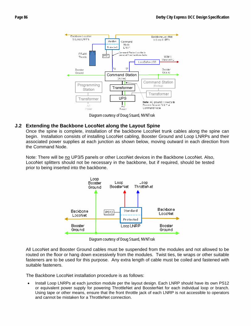
Page 86 Derby City Express DCC Design Specification
Diagram courtesy of Doug Stuard, NVNTrak
J.2 Extending the Backbone LocoNet along the Layout Spine Once the spine is complete, installation of the backbone LocoNet trunk cables along the spine can begin. Installation consists of installing LocoNet cabling, Booster Ground and Loop LNRPs and their associated power supplies at each junction as shown below, moving outward in each direction from the Command Node. Note: There will be no UP3/5 panels or other LocoNet devices in the Backbone LocoNet. Also, LocoNet splitters should not be necessary in the backbone, but if required, should be tested prior to being inserted into the backbone.
Diagram courtesy of Doug Stuard, NVNTrak
All LocoNet and Booster Ground cables must be suspended from the modules and not allowed to be routed on the floor or hang down excessively from the modules. Twist ties, tie wraps or other suitable fasteners are to be used for this purpose. Any extra length of cable must be coiled and fastened with suitable fasteners. The Backbone LocoNet installation procedure is as follows:
• Install Loop LNRPs at each junction module per the layout design. Each LNRP should have its own PS12 or equivalent power supply for powering ThrottleNet and BoosterNet for each individual loop or branch. Using tape or other means, ensure that the front throttle jack of each LNRP is not accessible to operators and cannot be mistaken for a ThrottleNet connection.
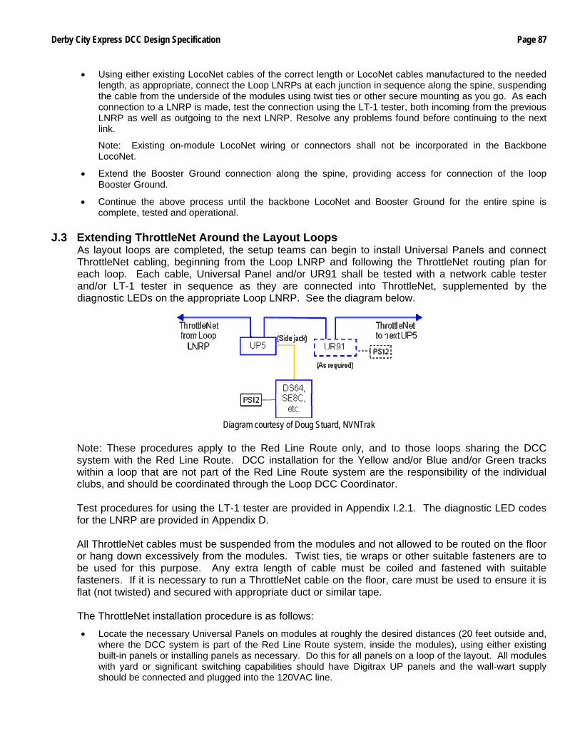
Derby City Express DCC Design Specification Page 87
• Using either existing LocoNet cables of the correct length or LocoNet cables manufactured to the needed length, as appropriate, connect the Loop LNRPs at each junction in sequence along the spine, suspending the cable from the underside of the modules using twist ties or other secure mounting as you go. As each connection to a LNRP is made, test the connection using the LT-1 tester, both incoming from the previous LNRP as well as outgoing to the next LNRP. Resolve any problems found before continuing to the next link.
Note: Existing on-module LocoNet wiring or connectors shall not be incorporated in the Backbone LocoNet.
• Extend the Booster Ground connection along the spine, providing access for connection of the loop Booster Ground.
• Continue the above process until the backbone LocoNet and Booster Ground for the entire spine is complete, tested and operational.
J.3 Extending ThrottleNet Around the Layout Loops
As layout loops are completed, the setup teams can begin to install Universal Panels and connect ThrottleNet cabling, beginning from the Loop LNRP and following the ThrottleNet routing plan for each loop. Each cable, Universal Panel and/or UR91 shall be tested with a network cable tester and/or LT-1 tester in sequence as they are connected into ThrottleNet, supplemented by the diagnostic LEDs on the appropriate Loop LNRP. See the diagram below.
Diagram courtesy of Doug Stuard, NVNTrak
Note: These procedures apply to the Red Line Route only, and to those loops sharing the DCC system with the Red Line Route. DCC installation for the Yellow and/or Blue and/or Green tracks within a loop that are not part of the Red Line Route system are the responsibility of the individual clubs, and should be coordinated through the Loop DCC Coordinator. Test procedures for using the LT-1 tester are provided in Appendix I.2.1. The diagnostic LED codes for the LNRP are provided in Appendix D. All ThrottleNet cables must be suspended from the modules and not allowed to be routed on the floor or hang down excessively from the modules. Twist ties, tie wraps or other suitable fasteners are to be used for this purpose. Any extra length of cable must be coiled and fastened with suitable fasteners. If it is necessary to run a ThrottleNet cable on the floor, care must be used to ensure it is flat (not twisted) and secured with appropriate duct or similar tape. The ThrottleNet installation procedure is as follows:
• Locate the necessary Universal Panels on modules at roughly the desired distances (20 feet outside and, where the DCC system is part of the Red Line Route system, inside the modules), using either existing built-in panels or installing panels as necessary. Do this for all panels on a loop of the layout. All modules with yard or significant switching capabilities should have Digitrax UP panels and the wall-wart supply should be connected and plugged into the 120VAC line.
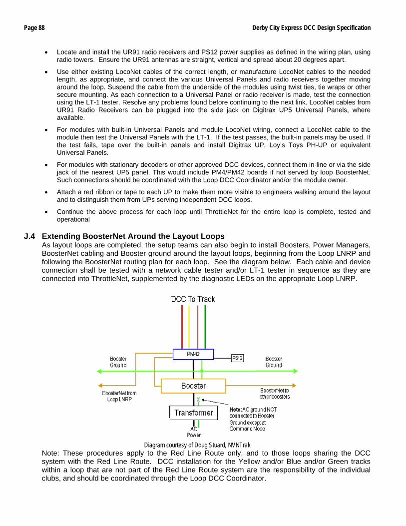
Page 88 Derby City Express DCC Design Specification
• Locate and install the UR91 radio receivers and PS12 power supplies as defined in the wiring plan, using radio towers. Ensure the UR91 antennas are straight, vertical and spread about 20 degrees apart.
• Use either existing LocoNet cables of the correct length, or manufacture LocoNet cables to the needed length, as appropriate, and connect the various Universal Panels and radio receivers together moving around the loop. Suspend the cable from the underside of the modules using twist ties, tie wraps or other secure mounting. As each connection to a Universal Panel or radio receiver is made, test the connection using the LT-1 tester. Resolve any problems found before continuing to the next link. LocoNet cables from UR91 Radio Receivers can be plugged into the side jack on Digitrax UP5 Universal Panels, where available.
• For modules with built-in Universal Panels and module LocoNet wiring, connect a LocoNet cable to the module then test the Universal Panels with the LT-1. If the test passes, the built-in panels may be used. If the test fails, tape over the built-in panels and install Digitrax UP, Loy’s Toys PH-UP or equivalent Universal Panels.
• For modules with stationary decoders or other approved DCC devices, connect them in-line or via the side jack of the nearest UP5 panel. This would include PM4/PM42 boards if not served by loop BoosterNet. Such connections should be coordinated with the Loop DCC Coordinator and/or the module owner.
• Attach a red ribbon or tape to each UP to make them more visible to engineers walking around the layout and to distinguish them from UPs serving independent DCC loops.
• Continue the above process for each loop until ThrottleNet for the entire loop is complete, tested and operational
J.4 Extending BoosterNet Around the Layout Loops
As layout loops are completed, the setup teams can also begin to install Boosters, Power Managers, BoosterNet cabling and Booster ground around the layout loops, beginning from the Loop LNRP and following the BoosterNet routing plan for each loop. See the diagram below. Each cable and device connection shall be tested with a network cable tester and/or LT-1 tester in sequence as they are connected into ThrottleNet, supplemented by the diagnostic LEDs on the appropriate Loop LNRP.
Diagram courtesy of Doug Stuard, NVNTrak
Note: These procedures apply to the Red Line Route only, and to those loops sharing the DCC system with the Red Line Route. DCC installation for the Yellow and/or Blue and/or Green tracks within a loop that are not part of the Red Line Route system are the responsibility of the individual clubs, and should be coordinated through the Loop DCC Coordinator.

Derby City Express DCC Design Specification Page 89
Test procedures for using the LT-1 tester are provided in Appendix I.2.1. The diagnostic LED codes for the LNRP are provided in Appendix D. All BoosterNet and Booster Ground cables must be suspended from the modules and not allowed to be routed on the floor or hang down excessively from the modules. Twist ties, tie wraps or other suitable fasteners are to be used for this purpose. Any extra length of cable must be coiled and fastened with a suitable fastener. If it is necessary to run a BoosterNet cable on the floor, care must be used to ensure it is flat (not twisted) and secured with appropriate duct or similar tape. Boosters and PM42s should be located on the floor beneath the geographical center of the electric block, as shown on the routing plan. The BoosterNet installation procedure is as follows:
• Locate Boosters/PM42s on the floor under the module at roughly the geographic center of the electrical district as shown on the BoosterNet plan. Booster power supplies should be plugged into the 120VAC line; any extra line cord length should be coiled and fastened with a suitable fastener. Do this for all Boosters on a sub-loop of the layout. Be sure the Scale Switch is set to the “N” position.
• At the electrical district boundaries ensure insulated rail joiners are installed and that the bus cables beneath the module are unplugged. Fasten a tag to those cables indicating they should not be connected.
• Use either existing black LocoNet cables of the correct length, or manufacture LocoNet cables to the needed length, as appropriate, and connect the various Boosters and PM42s together moving around the loop. Suspend the cable from the underside of the modules using twist ties or other secure mounting, and provide a direct vertical drop to the Booster, leaving a little slack in the vertical drop. Connect the booster and PM42 ground connections to the loop Booster Ground.
• As each connection to a Booster is completed, phase the input to the booster (see Appendix K Sections K.1 and K.2) and connect the booster output to the track, ensuring that the track polarity is correct (see Appendix K Section K.3). Resolve any problems found before continuing to the next Booster.
• For layout loops with centralized power distribution, connect the BoosterNet and Booster Ground cables to the central cabinet using a route that will expose the shortest distance of LocoNet cable on the floor. Cover the floor portion of the cable with duct tape from the drop point under modules to the central panel. Check booster phasing (Appendix K Sections K.1 and K.2) and track polarity (Appendix K.3) at the central cabinet. Resolve any problems before continuing.
• Continue the above process until BoosterNet for each loop is complete, tested and operational.
The Booster/PM42 ground installation procedure is as follows:
• A 12- or 14-gauge wire will be connected to the grounding block at the Command Station node and run in each direction along the spine, being suspended and fastened under each module in the spine.
• Connect a length of 12- or-14-gauge wire to the Ground terminal on the Booster; this wire should be long enough to extend from the Booster ground terminal to the Loop ground wire suspended from the module. Make sure that any PM42 ground wire is also connected to the Booster ground terminal.
Connect a length of wire in the same manner to Boosters/PM42s located in the spine.
• Connect this short lead to the Loop ground wire suspended from the module using a 3M Dual-Bladed Guillotine Insulation Displacement Connector (IDC).
For Boosters/PM42s in the spine connect this lead to the Spine ground wire suspended from the module using a 3M Dual-Bladed Guillotine Insulation Displacement Connector (IDC).
• Continue until all Boosters/PM42s in the Loop and Spine are connected to the Booster ground wire.

Page 90 Derby City Express DCC Design Specification
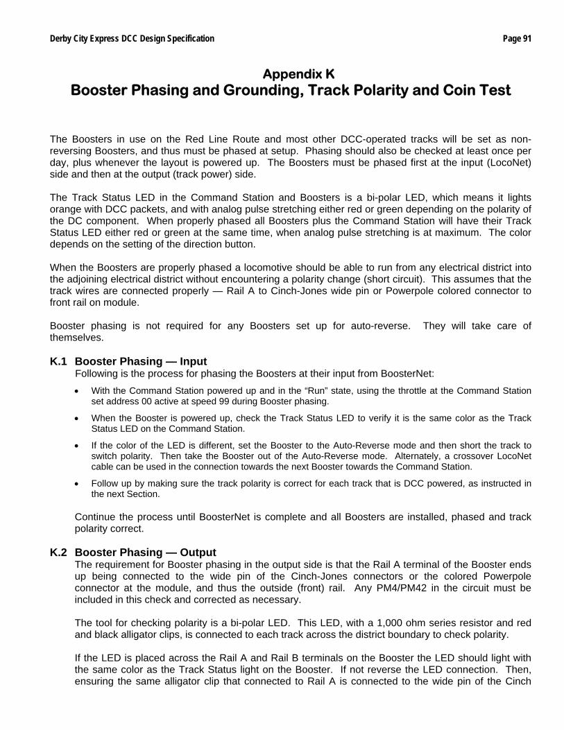
Derby City Express DCC Design Specification Page 91
Appendix K Booster Phasing and Grounding, Track Polarity and Coin Test
The Boosters in use on the Red Line Route and most other DCC-operated tracks will be set as non-reversing Boosters, and thus must be phased at setup. Phasing should also be checked at least once per day, plus whenever the layout is powered up. The Boosters must be phased first at the input (LocoNet) side and then at the output (track power) side. The Track Status LED in the Command Station and Boosters is a bi-polar LED, which means it lights orange with DCC packets, and with analog pulse stretching either red or green depending on the polarity of the DC component. When properly phased all Boosters plus the Command Station will have their Track Status LED either red or green at the same time, when analog pulse stretching is at maximum. The color depends on the setting of the direction button. When the Boosters are properly phased a locomotive should be able to run from any electrical district into the adjoining electrical district without encountering a polarity change (short circuit). This assumes that the track wires are connected properly — Rail A to Cinch-Jones wide pin or Powerpole colored connector to front rail on module. Booster phasing is not required for any Boosters set up for auto-reverse. They will take care of themselves. K.1 Booster Phasing — Input
Following is the process for phasing the Boosters at their input from BoosterNet:
• With the Command Station powered up and in the “Run” state, using the throttle at the Command Station set address 00 active at speed 99 during Booster phasing.
• When the Booster is powered up, check the Track Status LED to verify it is the same color as the Track Status LED on the Command Station.
• If the color of the LED is different, set the Booster to the Auto-Reverse mode and then short the track to switch polarity. Then take the Booster out of the Auto-Reverse mode. Alternately, a crossover LocoNet cable can be used in the connection towards the next Booster towards the Command Station.
• Follow up by making sure the track polarity is correct for each track that is DCC powered, as instructed in the next Section.
Continue the process until BoosterNet is complete and all Boosters are installed, phased and track polarity correct.
K.2 Booster Phasing — Output
The requirement for Booster phasing in the output side is that the Rail A terminal of the Booster ends up being connected to the wide pin of the Cinch-Jones connectors or the colored Powerpole connector at the module, and thus the outside (front) rail. Any PM4/PM42 in the circuit must be included in this check and corrected as necessary. The tool for checking polarity is a bi-polar LED. This LED, with a 1,000 ohm series resistor and red and black alligator clips, is connected to each track across the district boundary to check polarity. If the LED is placed across the Rail A and Rail B terminals on the Booster the LED should light with the same color as the Track Status light on the Booster. If not reverse the LED connection. Then, ensuring the same alligator clip that connected to Rail A is connected to the wide pin of the Cinch
Page 92 Derby City Express DCC Design Specification
Jones plug or colored Powerpole connector on the track feeder cable, check that the LED still lights with the same color. If not reverse the track power connections at the Rail A and Rail B terminals, and check again with the bi-polar LED. Note: Some modelers have equipped DPDT switches on the output side of the Booster or PM42. To correct track polarity it is necessary only to move the DPDT switch to the other position.
K.3 Checking Track Polarity
Theoretically, with all Boosters correctly phased at their input and the Rail A output of the Boosters/PM4s connected to the wide pin of the Cinch-Jones connectors or colored Powerpole connector and thus the outside rail, track polarity at electrical district boundaries should be automatically correct. In practice this is not a sure thing. Thus it is necessary to check track polarity at the district boundaries. The tool for checking polarity is a bi-polar LED. This LED, with a 1,000 ohm series resistor and red and black alligator clips, is connected to each track across the district boundary to check polarity. If the LED is placed across the two rails in the electrical district the LED should light with the same color as the Track Status light on the Booster. If not reverse the Rail A and B leads at the Booster or PM4. Note: Some modelers have equipped DPDT switches on the output side of the Booster or PM42. To correct track polarity it is necessary only to move the DPDT switch to the other position. If the LED lights when the clips are placed on like rails (either both outside rails or both inside rails) on either side of the boundary then the track polarity on one side of the boundary is wrong. If the LED remains dark the track polarity is correct. Track polarity will be checked and fixed by the BoosterNet crew as BoosterNet is connected around the layout.
K.4 The Coin Test Once the Booster is phased and Track Polarity correct, the team must take a coin (25¢) and go over every section of the track(s) in the electrical district. Place the coin across the track and verify the Booster shuts down virtually instantaneously. If there is a PM4/PM42 Power Manager between the Booster and track, verify that the PM4/PM42 shuts down before the Booster, and that the Booster does not trip. If you can count to one before the Booster trips, the track wiring is marginal, but acceptable. If you can count to two before the Booster trips, the track wiring must be augmented — either by re-wiring or doubling up on the wire. If the Booster does not trip at all the module wiring must be doubled or the module must be carefully examined for removal from the layout.
K.5 Booster Grounding Coincident with extending BoosterNet around the layout, the BoosterNet team will also install Booster ground wires. The ground wires will be routed following the same path as BoosterNet wiring and connected to the Ground terminal of each Booster. When connecting the ground wire to each Booster any existing ground from the Booster to any other source such as the metal case of the local power supply will be removed.
Derby City Express DCC Design Specification Page 93
Appendix L Power Up, System Reset and Shut Down Sequences
L.1 Power Up Sequence
To ensure proper operation, the power up sequence is to power the Command Station before any of the Boosters.
L.1.1 Command Station
Before any Boosters are powered, the Command Station must be powered up and stabilized, so it is generating proper DCC packets, especially the RailSyncs, even with Track Power off. This process should take approximately 2 – 3 seconds after the Mode Switch is placed in the Run position.
If the Boosters are powered up before the Command Station is generating packets, the results are anything from jumping locomotives to runaways.
Once the Command Station is powered up in Run mode, address 00 will be selected and the speed set to 99. This will be the operating mode during setup until all Boosters are installed and phased.
L.1.2 Boosters
Once the Command Station is powered up individual Boosters can be powered up. When all Boosters are powered up Track Power will be turned on at the Command Station. Address 00 will be selected at the Command Station and the speed set to 99. Booster phasing should then be verified. If any Boosters are determined to be out-of phase they should be re-phased and the track polarity verified at each electrical district boundary served by that Booster.
Once this process is complete, the speed of address 00 will be set to 00 and address 00 dispatched from the Command Station. Analog operation will be turned off by setting OPSW #20 at the Command Station to “c”.
L.2 System Reset
In the event major control problems are encountered such as an all slots full condition, corruption of the Command Station slot memory or other problems, and releasing slots via the JMRI LocoTools Slot Monitor does not resolve the problem, it may be necessary to perform a system reset. This process should only take about one minute, but it requires shutting down power to the DCC tracks. After the reset is performed all locomotive addresses including any UniVersal consists must be reprogrammed into the system.
Depending on the problem encountered there are two degrees of System Reset to be followed. For an all slots full or corruption of slot memory the Command Station must be reset using OPSW #36. For any other problem reset the system using the more inclusive OPSW #39. Special Note: An OPSW #39 reset will be carried out at the start of operations each day. Immediately following this reset, the LocoNet ID will be reset. L.2.1 OPSW #36 Reset
This reset clears all locomotive and consist information from the Command Station, idling all slots. The following is the process:
• At the Command Station, turn Track Power off.
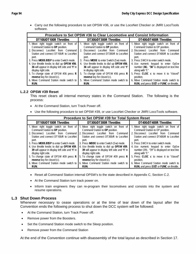
Page 94 Derby City Express DCC Design Specification
• Carry out the following procedure to set OPSW #36, or use the LocoNet Checker or JMRI LocoTools software.
Procedure to Set OPSW #36 to Clear Locomotive and Consist Information DT100/DT100R Throttles DT300/DT300R Throttles DT400/DT400R Throttles
1. Move right toggle switch on front of Command Station to OP position.
2. Disconnect LocoNet from Command Station and connect DT100/R to LocoNet port.
3. Press MODE/DISP to enter Switch mode. 4. Use throttle knobs to dial up OPSW #36.
36 will appear in display left side and “t” in display right side.
5. To change state of OPSW #36 press R reverse key for closed (c).
6. Move Command Station mode switch to RUN.
1. Move right toggle switch on front of Command Station to OP position.
2. Disconnect LocoNet from Command Station and connect DT300/R to LocoNet port.
3. Press MODE to enter Switch (Sw) mode. 4. Use throttle knobs to dial up OPSW #36.
36 will appear in display left side and “t” in display right side.
5. To change state of OPSW #36 press R reverse key for closed (c).
5. Move Command Station mode switch to RUN.
1. Move right toggle switch on front of Command Station to OP position.
2. Disconnect LocoNet from Command Station and connect DT400/R to LocoNet port.
3. Press SWCH to enter switch mode. 4. Use numeric keypad to enter OpSw
number (36). “36” is displayed on text line along with “t.”
5. Press CLOC c to move it to “closed” position.
6. Move Command Station mode switch to RUN, and press EXIT or FUNC on throttle.
L.2.2 OPSW #39 Reset
This reset clears all internal memory states in the Command Station. The following is the process:
• At the Command Station, turn Track Power off.
• Use the following procedure to set OPSW #39, or use LocoNet Checker or JMRI LocoTools software.
Procedure to Set OPSW #39 for Total System Reset DT100/DT100R Throttles DT300/DT300R Throttles DT400/DT400R Throttles
1. Move right toggle switch on front of Command Station to OP position.
2. Disconnect LocoNet from Command Station and connect DT100/R to LocoNet port.
3. Press MODE/DISP to enter Switch mode. 4. Use throttle knobs to dial up OPSW #39.
39 will appear in display left side and “t” in display right side.
5. To change state of OPSW #39 press R reverse key for closed (c).
6. Move Command Station mode switch to RUN.
1. Move right toggle switch on front of Command Station to OP position.
2. Disconnect LocoNet from Command Station and connect DT300/R to LocoNet port.
3. Press MODE to enter Switch (Sw) mode. 4. Use throttle knobs to dial up OPSW #39.
39 will appear in display left side and “t” in display right side.
5. To change state of OPSW #39 press R reverse key for closed (c).
6. Move Command Station mode switch to RUN.
1. Move right toggle switch on front of Command Station to OP position.
2. Disconnect LocoNet from Command Station and connect DT400/R to LocoNet port.
3. Press SWCH to enter switch mode. 4. Use numeric keypad to enter OpSw
number (39). “39” is displayed on text line along with “t.”
5. Press CLOC c to move it to “closed” position.
6. Move Command Station mode switch to RUN, and press EXIT or FUNC on throttle.
• Reset all Command Station internal OPSW’s to the state described in Appendix C, Section C.2.
• At the Command Station turn track power on.
• Inform train engineers they can re-program their locomotives and consists into the system and resume operations.
L.3 Shut Down Process
Whenever necessary to cease operations or at the time of tear down of the layout after the Convention ends the following process to shut down the DCC system will be followed:
• At the Command Station, turn Track Power off.
• Remove power from the Boosters.
• Set the Command Station mode switch to the Sleep position.
• Remove power from the Command Station
At the end of the Convention continue with disassembly of the total layout as described in Section 17.
Derby City Express DCC Design Specification Page 95
Appendix M Track and Wheel Cleaning
Clean track, clean turnout points and clean wheels are fundamental to reliable operation whether DC or DCC. All should be cleaned before the start of operations and again during operations as necessary to ensure continuous reliable operation. Peco turnout points provide a special cleaning need to ensure conductivity, especially with electrofrog turnouts. M.1 Cleaning Track
Track cleaning removes oxides and dirt, both of which interfere with electrical pickup. There are at several ways to clean track, all of which will be used at Derby City Express. These include:
• An abrasive rubbing pad, such as a Bright Boy.
Be careful with abrasives. Coarser grits scratch rails and minute ruts collect dirt. Finer grits polish railheads reducing traction.
• Track cleaning cars such as Aztec (liquid and abrasive) or Roco (abrasive).
Be especially careful with car-mounted abrasive blocks since the polishing of the railheads is longitudinal in the same direction as tractive force.
• Centerline track cleaning cars, two used in tandem. The cloth on the front roller should be wet and the cloth on the rear roller should be dry.
• Atlas/Tomix motorized track-cleaning car.
This car offers both liquid and abrasive cleaning as well as a vacuum effect to clean debris; only one effect can be used at a time.
• Wipe the track with a wet rag followed by a dry rag. Suitable cleaning fluids are 409 Detergent, Fantastik or Isopropyl Alcohol, and electronic solvents (contact cleaners and degreasers, but be sure they are styrene compatible). Other cleaning fluids such as Goo Gone and lighter fluid are prohibited at Derby City Express (Goo-Gone leaves a film on the track and lighter fluid is flammable). It is important to be sure the track has dried from any liquid track cleaner and that any residue has been removed. If trains are run while the track is still wet, then the train will spread any dirt that is coming off wheels or the residue of the cleaner all over the layout. Liquid track cleaning cars should be run only in special track cleaning trains. Abrasive track cleaning cars can be included in any train.
M.2 Cleaning Peco Turnouts
To clean Peco turnout points to improve electrical conductivity through the turnout, do the following:
• Fold a one-half inch by 4-inch slice of BLACK 320-grit wet/dry emery paper in half lengthwise.
• Place it between the stock and point rails. Hold the other point rail so the wet/dry paper is for sure going to contact both surfaces. Slowly move the paper back and forth; a few times is all that is needed.
• Repeat for the opposite stock/point rail.
• Place a drop or two of Atlas Conducta Lube & Cleaner on both stock/point rail pairs. This will improve the electrical contact of the points.
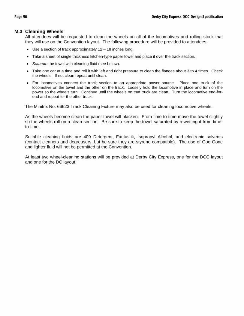
Page 96 Derby City Express DCC Design Specification
M.3 Cleaning Wheels All attendees will be requested to clean the wheels on all of the locomotives and rolling stock that they will use on the Convention layout. The following procedure will be provided to attendees:
• Use a section of track approximately 12 – 18 inches long.
• Take a sheet of single thickness kitchen-type paper towel and place it over the track section.
• Saturate the towel with cleaning fluid (see below).
• Take one car at a time and roll it with left and right pressure to clean the flanges about 3 to 4 times. Check the wheels. If not clean repeat until clean.
• For locomotives connect the track section to an appropriate power source. Place one truck of the locomotive on the towel and the other on the track. Loosely hold the locomotive in place and turn on the power so the wheels turn. Continue until the wheels on that truck are clean. Turn the locomotive end-for-end and repeat for the other truck.
The Minitrix No. 66623 Track Cleaning Fixture may also be used for cleaning locomotive wheels. As the wheels become clean the paper towel will blacken. From time-to-time move the towel slightly so the wheels roll on a clean section. Be sure to keep the towel saturated by rewetting it from time-to-time. Suitable cleaning fluids are 409 Detergent, Fantastik, Isopropyl Alcohol, and electronic solvents (contact cleaners and degreasers, but be sure they are styrene compatible). The use of Goo Gone and lighter fluid will not be permitted at the Convention. At least two wheel-cleaning stations will be provided at Derby City Express, one for the DCC layout and one for the DC layout.
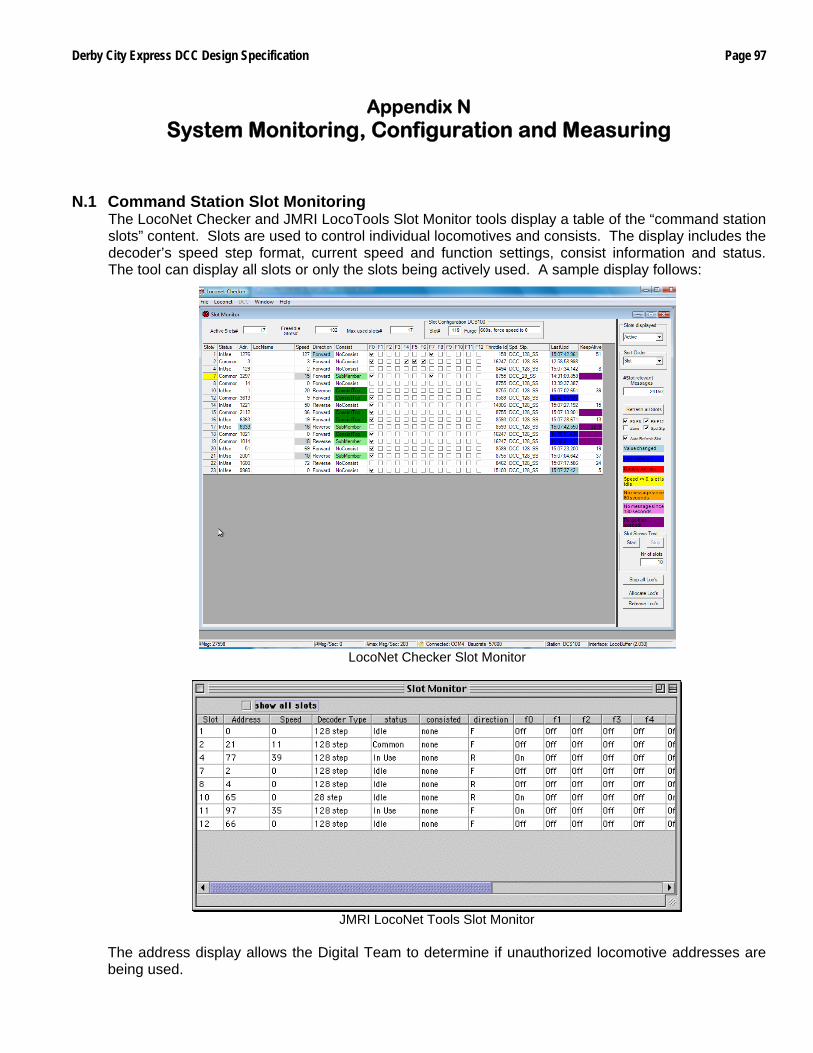
Derby City Express DCC Design Specification Page 97
Appendix N System Monitoring, Configuration and Measuring
N.1 Command Station Slot Monitoring
The LocoNet Checker and JMRI LocoTools Slot Monitor tools display a table of the “command station slots” content. Slots are used to control individual locomotives and consists. The display includes the decoder’s speed step format, current speed and function settings, consist information and status. The tool can display all slots or only the slots being actively used. A sample display follows:
LocoNet Checker Slot Monitor
JMRI LocoNet Tools Slot Monitor
The address display allows the Digital Team to determine if unauthorized locomotive addresses are being used.
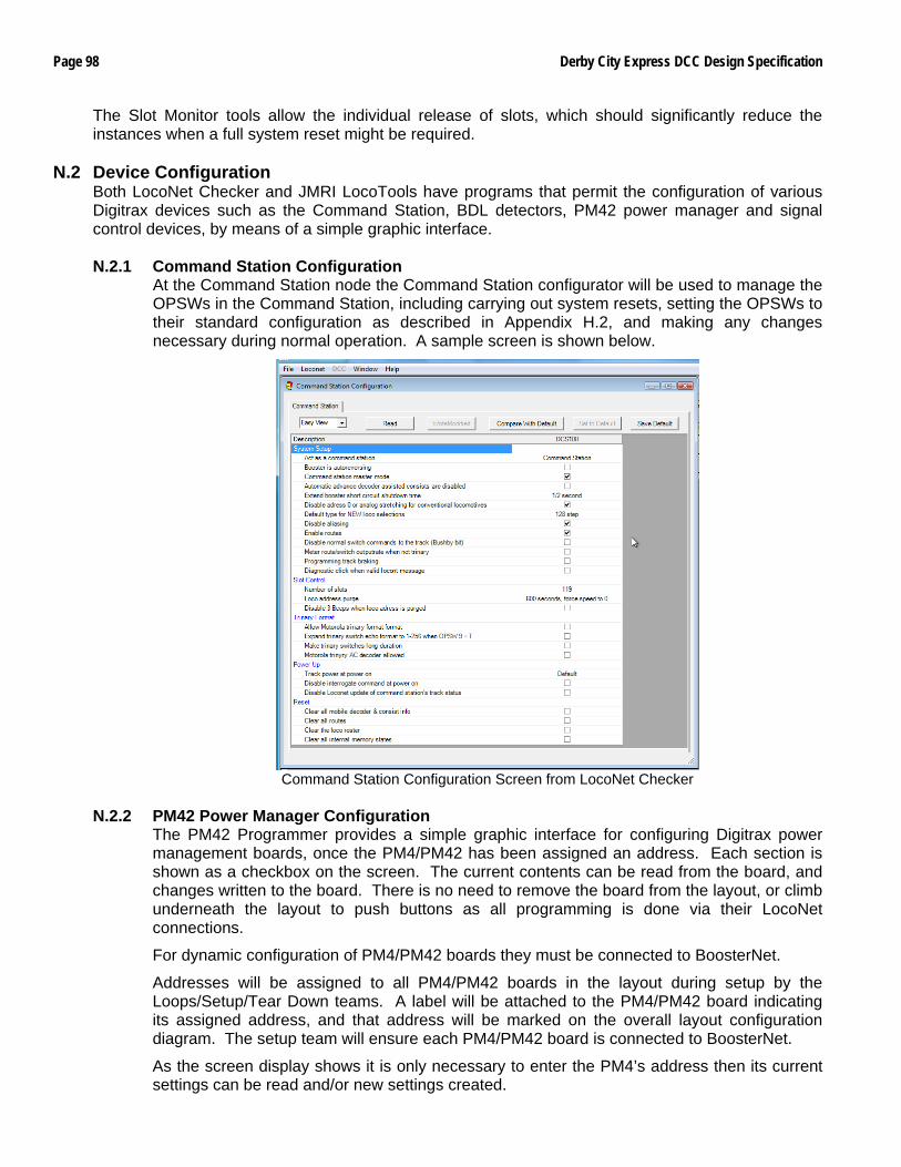
Page 98 Derby City Express DCC Design Specification
The Slot Monitor tools allow the individual release of slots, which should significantly reduce the instances when a full system reset might be required.
N.2 Device Configuration Both LocoNet Checker and JMRI LocoTools have programs that permit the configuration of various Digitrax devices such as the Command Station, BDL detectors, PM42 power manager and signal control devices, by means of a simple graphic interface. N.2.1 Command Station Configuration
At the Command Station node the Command Station configurator will be used to manage the OPSWs in the Command Station, including carrying out system resets, setting the OPSWs to their standard configuration as described in Appendix H.2, and making any changes necessary during normal operation. A sample screen is shown below.
Command Station Configuration Screen from LocoNet Checker
N.2.2 PM42 Power Manager Configuration
The PM42 Programmer provides a simple graphic interface for configuring Digitrax power management boards, once the PM4/PM42 has been assigned an address. Each section is shown as a checkbox on the screen. The current contents can be read from the board, and changes written to the board. There is no need to remove the board from the layout, or climb underneath the layout to push buttons as all programming is done via their LocoNet connections.
For dynamic configuration of PM4/PM42 boards they must be connected to BoosterNet.
Addresses will be assigned to all PM4/PM42 boards in the layout during setup by the Loops/Setup/Tear Down teams. A label will be attached to the PM4/PM42 board indicating its assigned address, and that address will be marked on the overall layout configuration diagram. The setup team will ensure each PM4/PM42 board is connected to BoosterNet.
As the screen display shows it is only necessary to enter the PM4’s address then its current settings can be read and/or new settings created.
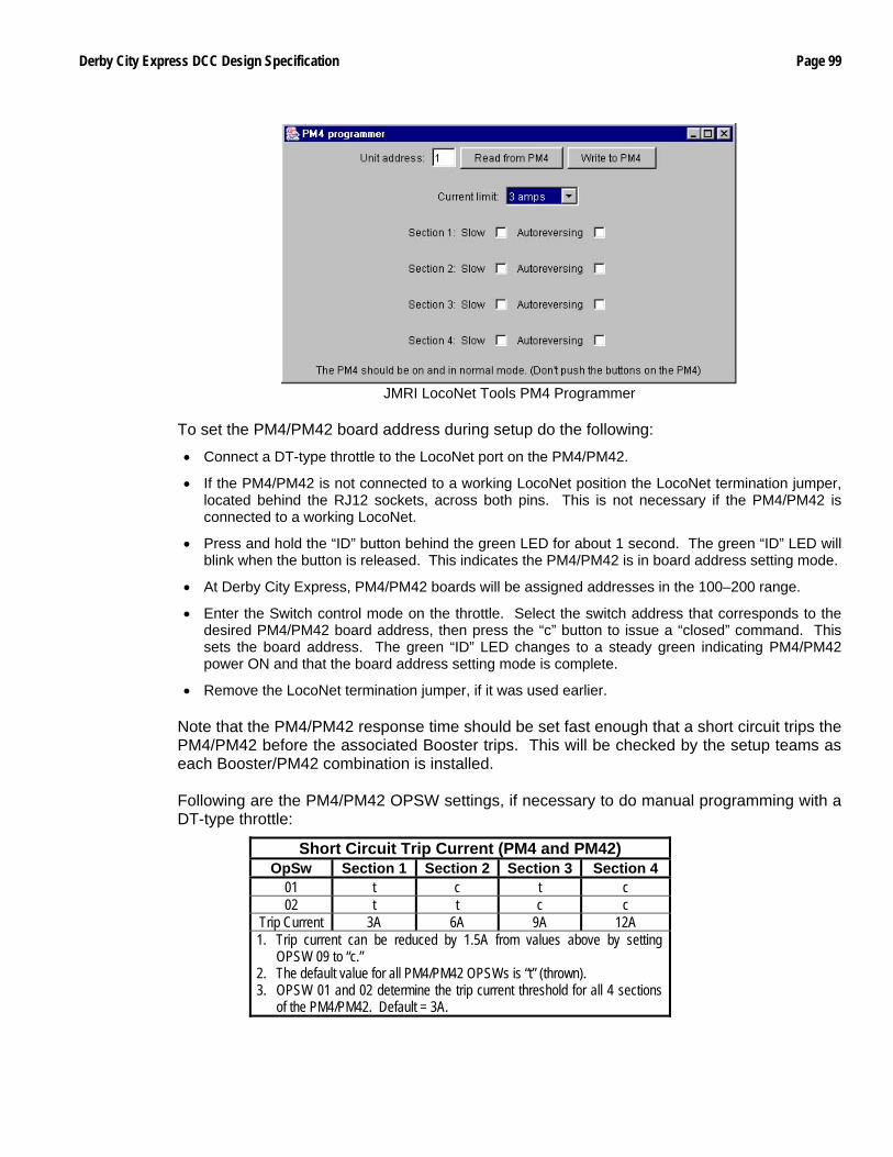
Derby City Express DCC Design Specification Page 99
JMRI LocoNet Tools PM4 Programmer
To set the PM4/PM42 board address during setup do the following:
• Connect a DT-type throttle to the LocoNet port on the PM4/PM42.
• If the PM4/PM42 is not connected to a working LocoNet position the LocoNet termination jumper, located behind the RJ12 sockets, across both pins. This is not necessary if the PM4/PM42 is connected to a working LocoNet.
• Press and hold the “ID” button behind the green LED for about 1 second. The green “ID” LED will blink when the button is released. This indicates the PM4/PM42 is in board address setting mode.
• At Derby City Express, PM4/PM42 boards will be assigned addresses in the 100–200 range.
• Enter the Switch control mode on the throttle. Select the switch address that corresponds to the desired PM4/PM42 board address, then press the “c” button to issue a “closed” command. This sets the board address. The green “ID” LED changes to a steady green indicating PM4/PM42 power ON and that the board address setting mode is complete.
• Remove the LocoNet termination jumper, if it was used earlier. Note that the PM4/PM42 response time should be set fast enough that a short circuit trips the PM4/PM42 before the associated Booster trips. This will be checked by the setup teams as each Booster/PM42 combination is installed. Following are the PM4/PM42 OPSW settings, if necessary to do manual programming with a DT-type throttle:
Short Circuit Trip Current (PM4 and PM42) OpSw Section 1 Section 2 Section 3 Section 4
01 t c t c 02 t t c c
Trip Current 3A 6A 9A 12A 1. Trip current can be reduced by 1.5A from values above by setting
OPSW 09 to “c.” 2. The default value for all PM4/PM42 OPSWs is “t” (thrown). 3. OPSW 01 and 02 determine the trip current threshold for all 4 sections
of the PM4/PM42. Default = 3A.
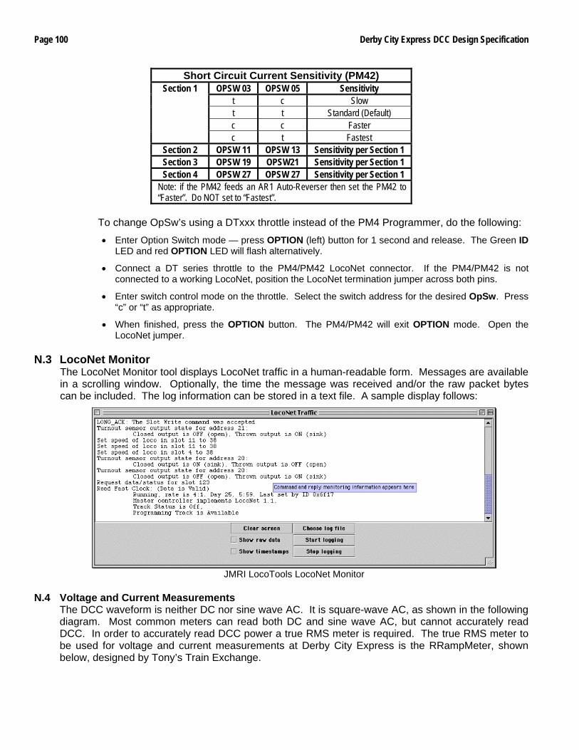
Page 100 Derby City Express DCC Design Specification
Short Circuit Current Sensitivity (PM42) OPSW 03 OPSW 05 Sensitivity
t c Slow t t Standard (Default) c c Faster
Section 1
c t Fastest Section 2 OPSW 11 OPSW 13 Sensitivity per Section 1 Section 3 OPSW 19 OPSW21 Sensitivity per Section 1 Section 4 OPSW 27 OPSW 27 Sensitivity per Section 1
Note: if the PM42 feeds an AR1 Auto-Reverser then set the PM42 to “Faster”. Do NOT set to “Fastest”.
To change OpSw’s using a DTxxx throttle instead of the PM4 Programmer, do the following:
• Enter Option Switch mode — press OPTION (left) button for 1 second and release. The Green ID LED and red OPTION LED will flash alternatively.
• Connect a DT series throttle to the PM4/PM42 LocoNet connector. If the PM4/PM42 is not connected to a working LocoNet, position the LocoNet termination jumper across both pins.
• Enter switch control mode on the throttle. Select the switch address for the desired OpSw. Press “c” or “t” as appropriate.
• When finished, press the OPTION button. The PM4/PM42 will exit OPTION mode. Open the LocoNet jumper.
N.3 LocoNet Monitor
The LocoNet Monitor tool displays LocoNet traffic in a human-readable form. Messages are available in a scrolling window. Optionally, the time the message was received and/or the raw packet bytes can be included. The log information can be stored in a text file. A sample display follows:
JMRI LocoTools LocoNet Monitor
N.4 Voltage and Current Measurements
The DCC waveform is neither DC nor sine wave AC. It is square-wave AC, as shown in the following diagram. Most common meters can read both DC and sine wave AC, but cannot accurately read DCC. In order to accurately read DCC power a true RMS meter is required. The true RMS meter to be used for voltage and current measurements at Derby City Express is the RRampMeter, shown below, designed by Tony’s Train Exchange.
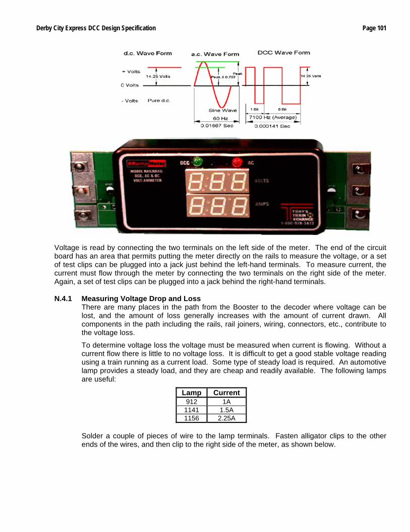
Derby City Express DCC Design Specification Page 101
Voltage is read by connecting the two terminals on the left side of the meter. The end of the circuit board has an area that permits putting the meter directly on the rails to measure the voltage, or a set of test clips can be plugged into a jack just behind the left-hand terminals. To measure current, the current must flow through the meter by connecting the two terminals on the right side of the meter. Again, a set of test clips can be plugged into a jack behind the right-hand terminals. N.4.1 Measuring Voltage Drop and Loss
There are many places in the path from the Booster to the decoder where voltage can be lost, and the amount of loss generally increases with the amount of current drawn. All components in the path including the rails, rail joiners, wiring, connectors, etc., contribute to the voltage loss.
To determine voltage loss the voltage must be measured when current is flowing. Without a current flow there is little to no voltage loss. It is difficult to get a good stable voltage reading using a train running as a current load. Some type of steady load is required. An automotive lamp provides a steady load, and they are cheap and readily available. The following lamps are useful:
Lamp Current 912 1A
1141 1.5A 1156 2.25A
Solder a couple of pieces of wire to the lamp terminals. Fasten alligator clips to the other ends of the wires, and then clip to the right side of the meter, as shown below.
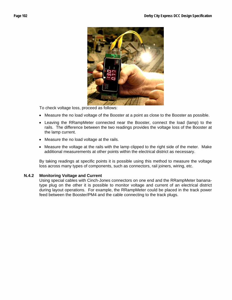
Page 102 Derby City Express DCC Design Specification
To check voltage loss, proceed as follows:
• Measure the no load voltage of the Booster at a point as close to the Booster as possible.
• Leaving the RRampMeter connected near the Booster, connect the load (lamp) to the rails. The difference between the two readings provides the voltage loss of the Booster at the lamp current.
• Measure the no load voltage at the rails.
• Measure the voltage at the rails with the lamp clipped to the right side of the meter. Make additional measurements at other points within the electrical district as necessary.
By taking readings at specific points it is possible using this method to measure the voltage loss across many types of components, such as connectors, rail joiners, wiring, etc.
N.4.2 Monitoring Voltage and Current Using special cables with Cinch-Jones connectors on one end and the RRampMeter banana-type plug on the other it is possible to monitor voltage and current of an electrical district during layout operations. For example, the RRampMeter could be placed in the track power feed between the Booster/PM4 and the cable connecting to the track plugs.
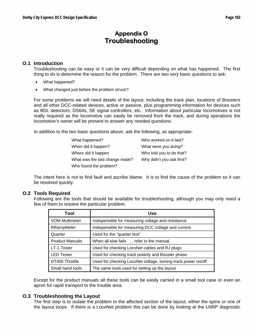
Derby City Express DCC Design Specification Page 103
Appendix O Troubleshooting
O.1 Introduction
Troubleshooting can be easy or it can be very difficult depending on what has happened. The first thing to do is determine the reason for the problem. There are two very basic questions to ask:
• What happened?
• What changed just before the problem struck?
For some problems we will need details of the layout, including the track plan, locations of Boosters and all other DCC-related devices, active or passive, plus programming information for devices such as BDL detectors, DS64s, SE signal controllers, etc. Information about particular locomotives is not really required as the locomotive can easily be removed from the track, and during operations the locomotive’s owner will be present to answer any needed questions. In addition to the two basic questions above, ask the following, as appropriate:
What happened? Who worked on it last? When did it happen? What were you doing? Where did it happen Who told you to do that? What was the last change made? Why didn’t you ask first? Who found the problem?
The intent here is not to find fault and ascribe blame. It is to find the cause of the problem so it can be resolved quickly.
O.2 Tools Required Following are the tools that should be available for troubleshooting, although you may only need a few of them to resolve the particular problem.
Tool Use VOM Multimeter Indispensible for measuring voltage and resistance RRampMeter Indispensible for measuring DCC voltage and current. Quarter Used for the “quarter test” Product Manuals When all else fails . . . refer to the manual. LT-1 Tester Used for checking LocoNet cables and RJ plugs LED Tester Used for checking track polarity and Booster phase DT400 Throttle Used for checking LocoNet voltage, turning track power on/off Small hand tools The same tools used for setting up the layout
Except for the product manuals all these tools can be easily carried in a small tool case or even an apron for rapid transport to the trouble area.
O.3 Troubleshooting the Layout
The first step is to isolate the problem to the affected section of the layout, either the spine or one of the layout loops. If there is a LocoNet problem this can be done by looking at the LNRP diagnostic

Page 104 Derby City Express DCC Design Specification
LEDs. If the LocoNet checks out then look for a track short circuit. This could be as simple as a locomotive or car sitting on turnouts and/or gaps. Check all gaps to be sure the gaps are still open and not closed due to temperature and humidity changes, or physical contact. If the track appears to be shorted, but the Booster is not beeping or the PM42 not tripped then remove all locomotives and lighted cars from the track and carry out the quarter test to determine if there is a wiring problem. Carefully check all track and turnouts in the affected district, using a Standard Gauge where necessary.
O.4 Troubleshooting Command Station/Booster Problems
If a Command Station/Booster and/or Booster is not performing properly on the layout, check the following items. If these do not bring the Command Station and/or Booster back to proper operation the unit should be replaced by a working unit, and then sent to Digitrax for repair. Before sending a DCS100 or DCS200 Command Station for repair, replace the CR2032 battery with a new battery and test again. Sometimes a low or dead CR2032 battery can create various problems. O.4.1 Command Station Audible Sounds
The DCS100/200 emits several beeps and clicks that provide information on its status and which can be helpful in troubleshooting any problems.
Sound DCS100/200 Meaning 1 Beep DCS powered on successfully or sent programming command. 3 Beeps Loco address has been “purged” due to non-use. 4 Beeps Route nesting error or too many entries cascaded 5 Beeps Booster short circuit shutdown. Fault alarm 6 Beeps Command Station already present in system 7 Beeps CMOS battery low condition 8 Beeps Memory ECC/checksum fail. Auto reset (no action) 9 Beeps DCS transmit failure. LocoNet fault 16 Beeps Software timeout failure. Auto reset (no action)
Continuous soft clicks Low input supply voltage (<9.5VDC or <8VAC) O.4.2 Nothing is Responding
O.4.2.1 No LEDs Lit on Front Panel of the Command Station/Booster. Check the following:
• Check the power supply to ensure the 120VAC plug is firmly inserted in the outlet, and there is power to the outlet.
• Check any fuses and/or circuit breakers on the power supply to ensure they have not blown or tripped. Replace with the same rated fuse. Apply power. If the fuse blows again disconnect the wires from the Command Station/Booster and try another fuse. If it still blows then replace the power supply.
• Once the power supply is verified as producing power, check the connections from the power supply to the Power In connections on the front of the Command Station/Booster. Ensure they are firmly attached.
• Swap out the power supply if there are still no lights on the Command Station/Booster.
• If the above does not correct the problem, replace the Command Station/Booster and send the faulty Command Station/Booster to Digitrax for repair.
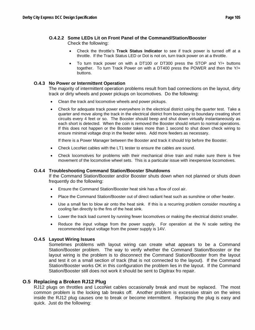
Derby City Express DCC Design Specification Page 105
O.4.2.2 Some LEDs Lit on Front Panel of the Command/Station/Booster
Check the following:
• Check the throttle’s Track Status Indicator to see if track power is turned off at a throttle. If the Track Status LED or Dot is not on, turn track power on at a throttle.
• To turn track power on with a DT100 or DT300 press the STOP and Y/+ buttons together. To turn Track Power on with a DT400 press the POWER and then the Y/+ buttons.
O.4.3 No Power or Intermittent Operation
The majority of intermittent operation problems result from bad connections on the layout, dirty track or dirty wheels and power pickups on locomotives. Do the following:
• Clean the track and locomotive wheels and power pickups.
• Check for adequate track power everywhere in the electrical district using the quarter test. Take a quarter and move along the track in the electrical district from boundary to boundary creating short circuits every 4 feet or so. The Booster should beep and shut down virtually instantaneously as each short is detected. When the coin is removed the Booster should return to normal operations. If this does not happen or the Booster takes more than 1 second to shut down check wiring to ensure minimal voltage drop in the feeder wires. Add more feeders as necessary.
If there is a Power Manager between the Booster and track it should trip before the Booster.
• Check LocoNet cables with the LT1 tester to ensure the cables are sound.
• Check locomotives for problems with their mechanical drive train and make sure there is free movement of the locomotive wheel sets. This is a particular issue with inexpensive locomotives.
O.4.4 Troubleshooting Command Station/Booster Shutdowns
If the Command Station/Booster and/or Booster shuts down when not planned or shuts down frequently do the following:
• Ensure the Command Station/Booster heat sink has a flow of cool air.
• Place the Command Station/Booster out of direct radiant heat such as sunshine or other heater.
• Use a small fan to blow air onto the heat sink. If this is a recurring problem consider mounting a cooling fan directly to the fins of the heat sink.
• Lower the track load current by running fewer locomotives or making the electrical district smaller.
• Reduce the input voltage from the power supply. For operation at the N scale setting the recommended input voltage from the power supply is 14V.
O.4.5 Layout Wiring Issues
Sometimes problems with layout wiring can create what appears to be a Command Station/Booster problem. The way to verify whether the Command Station/Booster or the layout wiring is the problem is to disconnect the Command Station/Booster from the layout and test it on a small section of track (that is not connected to the layout). If the Command Station/Booster works OK in this configuration the problem lies in the layout. If the Command Station/Booster still does not work it should be sent to Digitrax fro repair.
O.5 Replacing a Broken RJ12 Plug
RJ12 plugs on throttles and LocoNet cables occasionally break and must be replaced. The most common problem is the locking tab breaks off. Another problem is excessive strain on the wires inside the RJ12 plug causes one to break or become intermittent. Replacing the plug is easy and quick. Just do the following:
Page 106 Derby City Express DCC Design Specification
• Note the proper wire color as oriented to the existing plug. Looking at the RJ12 plug on a Digitrax throttle, with the locking tab up and away from you, as shown in the diagram below, the white wire is on the left.
• Cut off the damaged or failed plug as close to the plug as possible. Use diagonal wire cutters.
• Be sure the end of the cable is cut square and smooth. Use the jig built into the crimping tool to cut and remove the cable sheath back the proper distance.
• Insert one end of the cable into the cable jacket stripping blade of the crimping tool. Squeeze the handle and then carefully pull out the 6-wire cable from the tool. This operation removes the cable jacket exposing the 6 conductors. Be sure the ends of the wires are even; if necessary, make them even using the diagonal wire cutters. Spread the wires apart just slightly to ensure they will fit properly into the RJ12 plug.
• Slide the RJ12 connector onto the wires, making sure the wires stay lined up and the xx wire goes to the correct pin on the plug. The connector has six slots, one for each wire. Try to make each wire reach the end of its slot. The cable jacket/insulation should reach just beyond the end of the crimp point. If the insulation doesn't reach far enough inside the connector, cut the wires off just a bit more. If the cable jacket/insulation reaches too far past the crimp point or if the wires don't reach the end of their slot, simply trim off a little more jacket/insulation.
For the RJ12 connector to be very reliable it is very important to ensure the cable jacket is inserted into the clear body of the connector. This is the only strain relief these frail wires will receive. If you fail to do this, the connector will, sooner or later, fail and cause trouble.
• Again verify that all is in order and insert the connector into the crimping tool. Crimp it. This requires a little bit of strength, and you may need to use two hands.
• Test the cable to make sure it works properly (Appendix E, Section E.2). O.6 Troubleshooting LocoNet Problems
The NET indicator on the DCS100/DCS200 Command Station is a red LED that displays information about what the Command Station sees on LocoNet. When the LocoNet is wired correctly and is operating properly, the NET indicator will be on and it will flicker off any time a good LocoNet message is detected by the Command Station. The following table explains the various patterns for this indicator:
NET LED Indication Meaning Solid Red LocoNet OK
ON, Blink Off Command Station detects a valid LocoNet message Off Command Station detects a short circuit on LocoNet
Off, Blink Every 0.5 Second Command Station is in Option Set Up Mode
If an installed and working LocoNet starts causing problems or stops working, testing each part of the LocoNet will be necessary to isolate the problem cable or components, a process that is made easier with the protection capabilities of the LocoNet Repeaters. The only tool necessary to do this is the Digitrax LT1 tester coupled with the fault codes on the LNRP. Some faults can be better checked with a multimeter and test probes, but for expediency it is easier to replace any suspect cable or component.
Derby City Express DCC Design Specification Page 107
The starting point for testing is at the LocoNet Repeater (LNRP) with the active fault indication. For all tests be sure there is a Digitrax DTxxx throttle plugged into either the LNRP throttle jack or a Universal Panel in the affected district located close to the LNRP. Following is the procedure:
• Starting at the appropriate LNRP remove one main branch of the LocoNet and plug in the LT1. All 4 LEDs should light. If less than 4 LEDs or none light the problem is in the LNRP. If all 4 LEDs light then the problem is in the LocoNet branch disconnected.
• Move out the affected branch to the end of the first cable, disconnect it and plug in the LT1 there. If less than 4 LEDs or none light then replace that cable.
• Continue along the spine or down the loop until the LT1 fails to light or less than 4 LEDs light, and replace the bad cable. If a Universal Panel is determined to be the problem either replace it or bypass it.
Types of LocoNet problems to check for are:
• Plugs that aren’t fully inserted into the jacks (insert the plug, then pull it back just a bit so that it “clicks” into place).
• Male plugs that haven’t been properly crimped.
• Loose or broken wires on RJ12 telco jacks.
• A less common problem is one of the pins in the LocoNet port is crossed over another. Look inside each port to be sure that the pins are lined up in their respective slots.
• Using 4-wire components (cables and plugs)
• Using Ethernet RJ45 components (jacks, plugs, Cat 5 cables) If necessary to measure, the following are normal LocoNet voltages, all measured to ground:
• 1. White: 5 – 7 VDC
• 2. Black: ground
• 3. Red 10 -15 VDC. Measure between the pin or wire and ground.
• 4. Green: 10 – 15 VDC. Measure between the pin or wire and ground.
• 5. Yellow: Ground
• 6. Blue: 5 – 7 VDC
O.7 Troubleshooting UP3 or UP5 Universal Panels The following can happen to a Digitrax UP3 or UP5 Universal Panel only if it is connected to Track Power (via the rail screw terminals on the back) and a throttle with a damaged RJ12 connector is plugged in. The resulting damage is to blow one of the 500mA diodes in series with the external power connections to the UP3. The problem throttle can have a damaged RJ12 plug, a bad crimp or a loose wire inside such that this throttle causes a short between one of the track terminals on the rear and the Booster via LocoNet. This is caused by the throttle shorting two of the pins in the UP throttle receptacle together either at the connector or in the throttle. The current path would pass the Booster’s power through the diode thus damaging it. Normally these diodes see very little current. This may not always damage the diode and the throttle in question may appear to operate properly. Also, enough load may be presented that the Booster does not see a short. So this throttle may be used for a while until another diode blows. The UP3/UP5s may fail anywhere on the layout, in any electrical district, into which this throttle plugs.
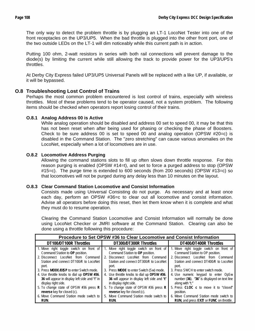
Page 108 Derby City Express DCC Design Specification
The only way to detect the problem throttle is by plugging an LT-1 LocoNet Tester into one of the front receptacles on the UP3/UP5. When the bad throttle is plugged into the other front port, one of the two outside LEDs on the LT-1 will dim noticeably while this current path is in action. Putting 100 ohm, 2-watt resistors in series with both rail connections will prevent damage to the diode(s) by limiting the current while still allowing the track to provide power for the UP3/UP5’s throttles. At Derby City Express failed UP3/UP5 Universal Panels will be replaced with a like UP, if available, or it will be bypassed.
O.8 Troubleshooting Lost Control of Trains Perhaps the most common problem encountered is lost control of trains, especially with wireless throttles. Most of these problems tend to be operator caused, not a system problem. The following items should be checked when operators report losing control of their trains.
O.8.1 Analog Address 00 is Active
While analog operation should be disabled and address 00 set to speed 00, it may be that this has not been reset when after being used for phasing or checking the phase of Boosters. Check to be sure address 00 is set to speed 00 and analog operation (OPSW #20=c) is disabled in the Command Station. The "zero stretching" can cause various anomalies on the LocoNet, especially when a lot of locomotives are in use.
O.8.2 Locomotive Address Purging
Allowing the command stations slots to fill up often slows down throttle response. For this reason purging is enabled (OPSW #14=t), and set to force a purged address to stop (OPSW #15=c). The purge time is extended to 600 seconds (from 200 seconds) (OPSW #13=c) so that locomotives will not be purged during any delay less than 10 minutes on the layout.
O.8.3 Clear Command Station Locomotive and Consist Information
Consists made using Universal Consisting do not purge. As necessary and at least once each day, perform an OPSW #36=c to clear out all locomotive and consist information. Advise all operators before doing this reset, then let them know when it is complete and what they must do to resume operation. Clearing the Command Station Locomotive and Consist Information will normally be done using LocoNet Checker or JMRI software at the Command Station. Clearing can also be done using a throttle following this procedure:
Procedure to Set OPSW #36 to Clear Locomotive and Consist Information DT100/DT100R Throttles DT300/DT300R Throttles DT400/DT400R Throttles
1. Move right toggle switch on front of Command Station to OP position.
2. Disconnect LocoNet from Command Station and connect DT100/R to LocoNet port.
3. Press MODE/DISP to enter Switch mode. 4. Use throttle knobs to dial up OPSW #36.
36 will appear in display left side and “t” in display right side.
5. To change state of OPSW #36 press R reverse key for closed (c).
6. Move Command Station mode switch to RUN.
1. Move right toggle switch on front of Command Station to OP position.
2. Disconnect LocoNet from Command Station and connect DT300/R to LocoNet port.
3. Press MODE to enter Switch (Sw) mode. 4. Use throttle knobs to dial up OPSW #36.
36 will appear in display left side and “t” in display right side.
5. To change state of OPSW #36 press R reverse key for closed (c).
5. Move Command Station mode switch to RUN.
1. Move right toggle switch on front of Command Station to OP position.
2. Disconnect LocoNet from Command Station and connect DT400/R to LocoNet port.
3. Press SWCH to enter switch mode. 4. Use numeric keypad to enter OpSw
number (36). “36” is displayed on text line along with “t.”
5. Press CLOC c to move it to “closed” position.
6. Move Command Station mode switch to RUN, and press EXIT or FUNC on throttle.
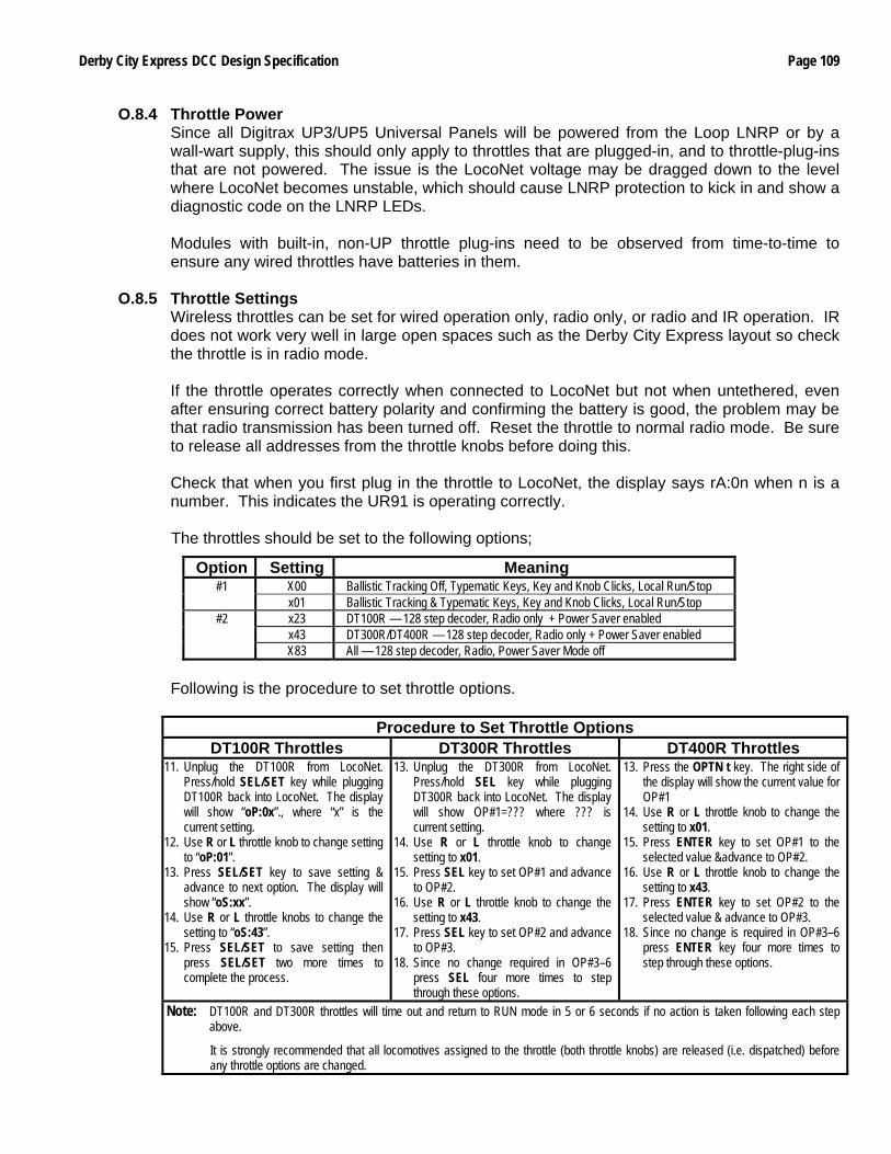
Derby City Express DCC Design Specification Page 109
O.8.4 Throttle Power Since all Digitrax UP3/UP5 Universal Panels will be powered from the Loop LNRP or by a wall-wart supply, this should only apply to throttles that are plugged-in, and to throttle-plug-ins that are not powered. The issue is the LocoNet voltage may be dragged down to the level where LocoNet becomes unstable, which should cause LNRP protection to kick in and show a diagnostic code on the LNRP LEDs. Modules with built-in, non-UP throttle plug-ins need to be observed from time-to-time to ensure any wired throttles have batteries in them.
O.8.5 Throttle Settings
Wireless throttles can be set for wired operation only, radio only, or radio and IR operation. IR does not work very well in large open spaces such as the Derby City Express layout so check the throttle is in radio mode. If the throttle operates correctly when connected to LocoNet but not when untethered, even after ensuring correct battery polarity and confirming the battery is good, the problem may be that radio transmission has been turned off. Reset the throttle to normal radio mode. Be sure to release all addresses from the throttle knobs before doing this. Check that when you first plug in the throttle to LocoNet, the display says rA:0n when n is a number. This indicates the UR91 is operating correctly. The throttles should be set to the following options;
Option Setting Meaning X00 Ballistic Tracking Off, Typematic Keys, Key and Knob Clicks, Local Run/Stop #1 x01 Ballistic Tracking & Typematic Keys, Key and Knob Clicks, Local Run/Stop x23 DT100R — 128 step decoder, Radio only + Power Saver enabled x43 DT300R/DT400R — 128 step decoder, Radio only + Power Saver enabled
#2
X83 All — 128 step decoder, Radio, Power Saver Mode off Following is the procedure to set throttle options.
Procedure to Set Throttle Options DT100R Throttles DT300R Throttles DT400R Throttles
11. Unplug the DT100R from LocoNet. Press/hold SEL/SET key while plugging DT100R back into LocoNet. The display will show “oP:0x”., where “x” is the current setting.
12. Use R or L throttle knob to change setting to “oP:01”.
13. Press SEL/SET key to save setting & advance to next option. The display will show “oS:xx”.
14. Use R or L throttle knobs to change the setting to “oS:43”.
15. Press SEL/SET to save setting then press SEL/SET two more times to complete the process.
13. Unplug the DT300R from LocoNet. Press/hold SEL key while plugging DT300R back into LocoNet. The display will show OP#1=??? where ??? is current setting.
14. Use R or L throttle knob to change setting to x01.
15. Press SEL key to set OP#1 and advance to OP#2.
16. Use R or L throttle knob to change the setting to x43.
17. Press SEL key to set OP#2 and advance to OP#3.
18. Since no change required in OP#3–6 press SEL four more times to step through these options.
13. Press the OPTN t key. The right side of the display will show the current value for OP#1
14. Use R or L throttle knob to change the setting to x01.
15. Press ENTER key to set OP#1 to the selected value &advance to OP#2.
16. Use R or L throttle knob to change the setting to x43.
17. Press ENTER key to set OP#2 to the selected value & advance to OP#3.
18. Since no change is required in OP#3–6 press ENTER key four more times to step through these options.
Note: DT100R and DT300R throttles will time out and return to RUN mode in 5 or 6 seconds if no action is taken following each step above.
It is strongly recommended that all locomotives assigned to the throttle (both throttle knobs) are released (i.e. dispatched) before any throttle options are changed.
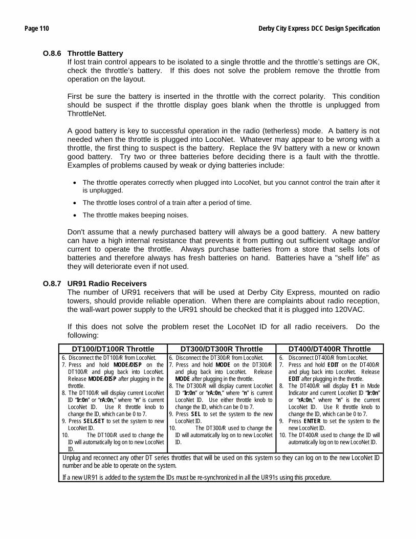
Page 110 Derby City Express DCC Design Specification
O.8.6 Throttle Battery If lost train control appears to be isolated to a single throttle and the throttle’s settings are OK, check the throttle’s battery. If this does not solve the problem remove the throttle from operation on the layout. First be sure the battery is inserted in the throttle with the correct polarity. This condition should be suspect if the throttle display goes blank when the throttle is unplugged from ThrottleNet. A good battery is key to successful operation in the radio (tetherless) mode. A battery is not needed when the throttle is plugged into LocoNet. Whatever may appear to be wrong with a throttle, the first thing to suspect is the battery. Replace the 9V battery with a new or known good battery. Try two or three batteries before deciding there is a fault with the throttle. Examples of problems caused by weak or dying batteries include: • The throttle operates correctly when plugged into LocoNet, but you cannot control the train after it
is unplugged.
• The throttle loses control of a train after a period of time.
• The throttle makes beeping noises. Don't assume that a newly purchased battery will always be a good battery. A new battery can have a high internal resistance that prevents it from putting out sufficient voltage and/or current to operate the throttle. Always purchase batteries from a store that sells lots of batteries and therefore always has fresh batteries on hand. Batteries have a "shelf life" as they will deteriorate even if not used.
O.8.7 UR91 Radio Receivers
The number of UR91 receivers that will be used at Derby City Express, mounted on radio towers, should provide reliable operation. When there are complaints about radio reception, the wall-wart power supply to the UR91 should be checked that it is plugged into 120VAC. If this does not solve the problem reset the LocoNet ID for all radio receivers. Do the following:
DT100/DT100R Throttle DT300/DT300R Throttle DT400/DT400R Throttle 6. Disconnect the DT100/R from LocoNet. 7. Press and hold MODE/DISP on the
DT100/R and plug back into LocoNet. Release MODE/DISP after plugging in the throttle.
8. The DT100/R will display current LocoNet ID “Ir:0n” or “rA:0n,” where “n” is current LocoNet ID. Use R throttle knob to change the ID, which can be 0 to 7.
9. Press SEL/SET to set the system to new LocoNet ID.
10. The DT100/R used to change the ID will automatically log on to new LocoNet ID.
6. Disconnect the DT300/R from LocoNet. 7. Press and hold MODE on the DT300/R
and plug back into LocoNet. Release MODE after plugging in the throttle.
8. The DT300/R will display current LocoNet ID “Ir:0n” or “rA:0n,” where “n” is current LocoNet ID. Use either throttle knob to change the ID, which can be 0 to 7.
9. Press SEL to set the system to the new LocoNet ID.
10. The DT300/R used to change the ID will automatically log on to new LocoNet ID.
6. Disconnect DT400/R from LocoNet. 7. Press and hold EDIT on the DT400/R
and plug back into LocoNet. Release EDIT after plugging in the throttle.
8. The DT400/R will display E1 in Mode Indicator and current LocoNet ID “Ir:0n” or “rA:0n,” where “n” is the current LocoNet ID. Use R throttle knob to change the ID, which can be 0 to 7.
9. Press ENTER to set the system to the new LocoNet ID.
10. The DT400/R used to change the ID will automatically log on to new LocoNet ID.
Unplug and reconnect any other DT series throttles that will be used on this system so they can log on to the new LocoNet ID number and be able to operate on the system.
If a new UR91 is added to the system the IDs must be re-synchronized in all the UR91s using this procedure.
Derby City Express DCC Design Specification Page 111
O.8.8 Radio Deadspots Several UR91 radio receivers will be strategically located around the DCC portion of the layout to minimize any problems with radio reception. However, radio dead spots may still be encountered. In most cases simply moving a foot or two should correct the problem. In normal operation the best orientation is to hold the throttle from about horizontal to about 30 degrees upward in a natural hand position, about 12” out from the body.
O.8.9 Command Station Reset
If lost control issues cannot be resolved by application of the recommendations above, then a Command Station reset (OPSW #39) should be carried out.
O.9 Short Circuits at Insulated Rail Frogs
This problem is encountered with insulfrog turnouts and crossings. The problem does not exist with electrofrog turnouts. At insulated frogs the two rails in the frog are separated by a thin section of plastic. It is possible for the wheels treads of locomotives, lighted cars and any cars with metal wheels to momentarily bridge the insulation gap and contact both rails at the same time as the train passes through the frog, causing a short circuit. With DC (analog) power, most power packs take a finite amount of time to detect the short circuit and shut down. By the time this occurs the locomotive/car has usually moved on and no longer bridges the gap. The train continues to run. With DCC (digital) power, detection of the short circuit and shut down of the Booster/PM42 is much faster, sometimes instantaneous. The effect on the train will depend on its speed and whether the locomotive(s) have flywheels. A train traveling faster and/or having flywheels will probably continue past the frog thus ending the short circuit. There may be a noticeable jerk in speed, however. This scenario will repeat as each wheel set in the locomotives and cars pass the frog. It will also cause jerkiness in the speed of all trains in the same power district. A train traveling slower and/or not having flywheels will probably jerk to a stop as a result of the short circuit. The train will probably have to be pulled through the frog to clear the short circuit. All trains in the same power district are affected. The solution is to modify the frog to prevent the short circuit from happening. There are at least three (3) ways of doing this: 1) Brush a thin coat of clear nail polish on the end of the frog where the short occurs. This is the fastest
solution, but the frog must be recoated from time-to-time as the nail polish wears off due to train traffic through the frog.
2) Glue thin paper or plastic to the frog to cover the area where a short may occur. If using plastic, file down
the frog slightly so the top surface including the plastic overlay is flat. Also file the shape of the plastic to match the frog.
3) Using a Dremel tool, make the rail V-shaped, with the apex of the “V” the inside of the rails, where the
flange contacts the rail. Method 3 is preferred as it is permanent, but Method 1 is acceptable at Derby City Express for expediency.
Page 112 Derby City Express DCC Design Specification
O.10 Troubleshooting Automatic Reverse Problems Auto-Reversing Controllers such as the Digitrax AR1 are used for automatically switching track polarity when a train enters and leaves a reversing section on the layout. The input power to the controller is taken from the Rail A and Rail B of the electrical district next to the reversing section and the output power from the controller is connected to the reversing track. If the automatic reverse controller does not switch polarity as the train enters or exits the reversing section, check the following:
• Ensure the entrance and exit boundaries of the reversing section connect to the same electrical district that is powering the automatic reverse controller.
This is important — the reversing section must be on the same power district as the adjacent approach trackage, both for input and output. Where one end will be in a different power district create a short section of track powered from the same district as the AR1. This short section of track should be at least as long as the longest single locomotive, such that it cannot bridge power back into a district powered from a different Booster or Power Manager section.
• Ensure there are double gaps in both rails at each end of the reversing section, and that the gaps have not closed.
• Check to be sure there is not more than one entrance to and one exit from the reversing section. If there are optional routes in the reversing section make sure all boundaries are double-gapped, and the connecting tracks are in the same electrical district as the input to the automatic reversing controller.
• If using a Digitrax AR1 Automatic Reversing Controller check the trip current adjustment. This permits setting the current (range is 0.25A to 8A) at which the reversing section reverses when the train crosses the gaps into the reversing section.
Turning the adjustment screw clockwise increases the current trip point, and vice-versa. The total adjustment is approximately one-half revolution of the adjustment screw.
When adjusting the trip current there should be a full load on the reversing section, i.e. the total number of locomotives that will be in the reversing section.
Do the following to adjust the AR1 trip current:
• Turn the current adjustment screw to the midpoint position.
• Turn on track power
• Place a locomotive(s) on the track and operate it /them into the reversing section. The AR1 should trip one time at the beginning of the section or at the end of the section. It should not trip more than once while the locomotives are in the reversing section.
• If the AR1 trips more than once the trip current is set too low. Turn the current adjustment screw clockwise slightly to increase the current trip point. Operate the locomotives into the section as above. Repeat as necessary until the AR1 trips once while the train goes through the reversing section.
• If the AR1 does not trip and the Booster shuts down, the trip current is set too high. Remove the locomotives from the reversing section and allow the Booster to reset. Turn the current adjusting screw counterclockwise slightly and repeat the test until the train trips the AR1 once without shutting down the Booster.
If the AR1 is powered from a district that in turn is powered through a PM42 Power Manager do not use the “fastest setting” in the PM42 Short Circuit Settings section. Use either the “Standard” or the “Faster” settings. See the following table:
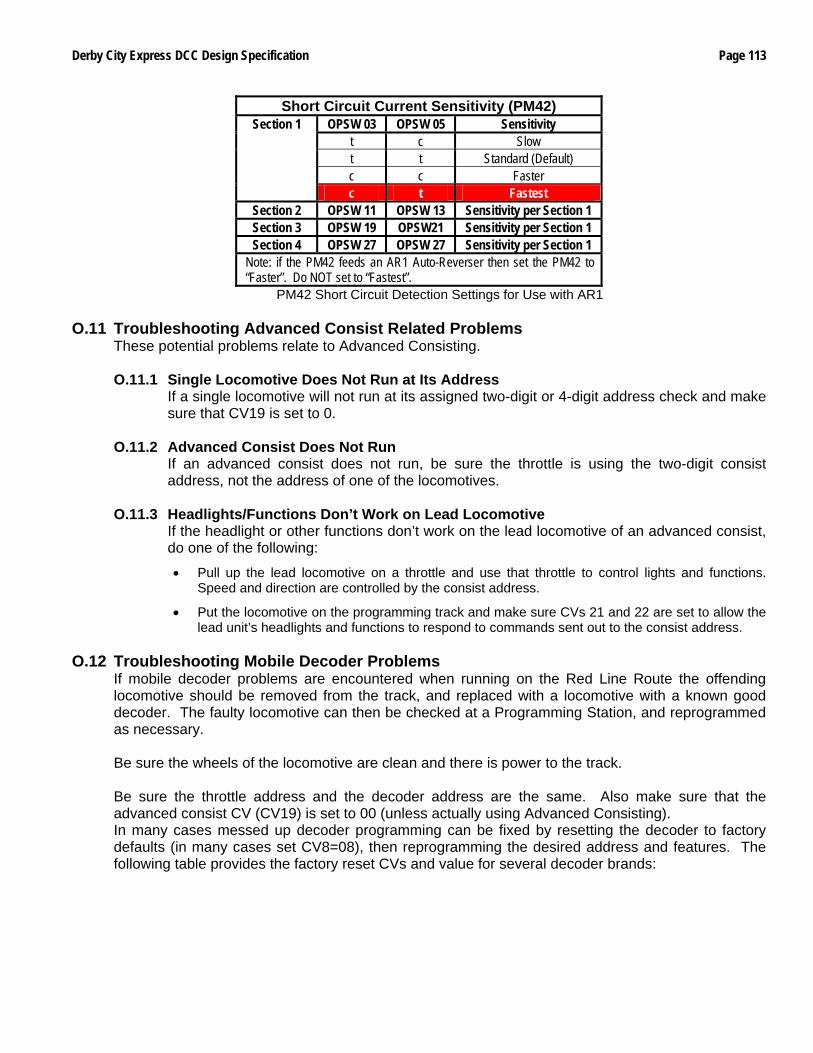
Derby City Express DCC Design Specification Page 113
Short Circuit Current Sensitivity (PM42) OPSW 03 OPSW 05 Sensitivity
t c Slow t t Standard (Default) c c Faster
Section 1
c t Fastest Section 2 OPSW 11 OPSW 13 Sensitivity per Section 1 Section 3 OPSW 19 OPSW21 Sensitivity per Section 1 Section 4 OPSW 27 OPSW 27 Sensitivity per Section 1
Note: if the PM42 feeds an AR1 Auto-Reverser then set the PM42 to “Faster”. Do NOT set to “Fastest”.
PM42 Short Circuit Detection Settings for Use with AR1
O.11 Troubleshooting Advanced Consist Related Problems These potential problems relate to Advanced Consisting.
O.11.1 Single Locomotive Does Not Run at Its Address
If a single locomotive will not run at its assigned two-digit or 4-digit address check and make sure that CV19 is set to 0.
O.11.2 Advanced Consist Does Not Run If an advanced consist does not run, be sure the throttle is using the two-digit consist address, not the address of one of the locomotives.
O.11.3 Headlights/Functions Don’t Work on Lead Locomotive If the headlight or other functions don’t work on the lead locomotive of an advanced consist, do one of the following:
• Pull up the lead locomotive on a throttle and use that throttle to control lights and functions. Speed and direction are controlled by the consist address.
• Put the locomotive on the programming track and make sure CVs 21 and 22 are set to allow the lead unit’s headlights and functions to respond to commands sent out to the consist address.
O.12 Troubleshooting Mobile Decoder Problems
If mobile decoder problems are encountered when running on the Red Line Route the offending locomotive should be removed from the track, and replaced with a locomotive with a known good decoder. The faulty locomotive can then be checked at a Programming Station, and reprogrammed as necessary. Be sure the wheels of the locomotive are clean and there is power to the track. Be sure the throttle address and the decoder address are the same. Also make sure that the advanced consist CV (CV19) is set to 00 (unless actually using Advanced Consisting). In many cases messed up decoder programming can be fixed by resetting the decoder to factory defaults (in many cases set CV8=08), then reprogramming the desired address and features. The following table provides the factory reset CVs and value for several decoder brands:
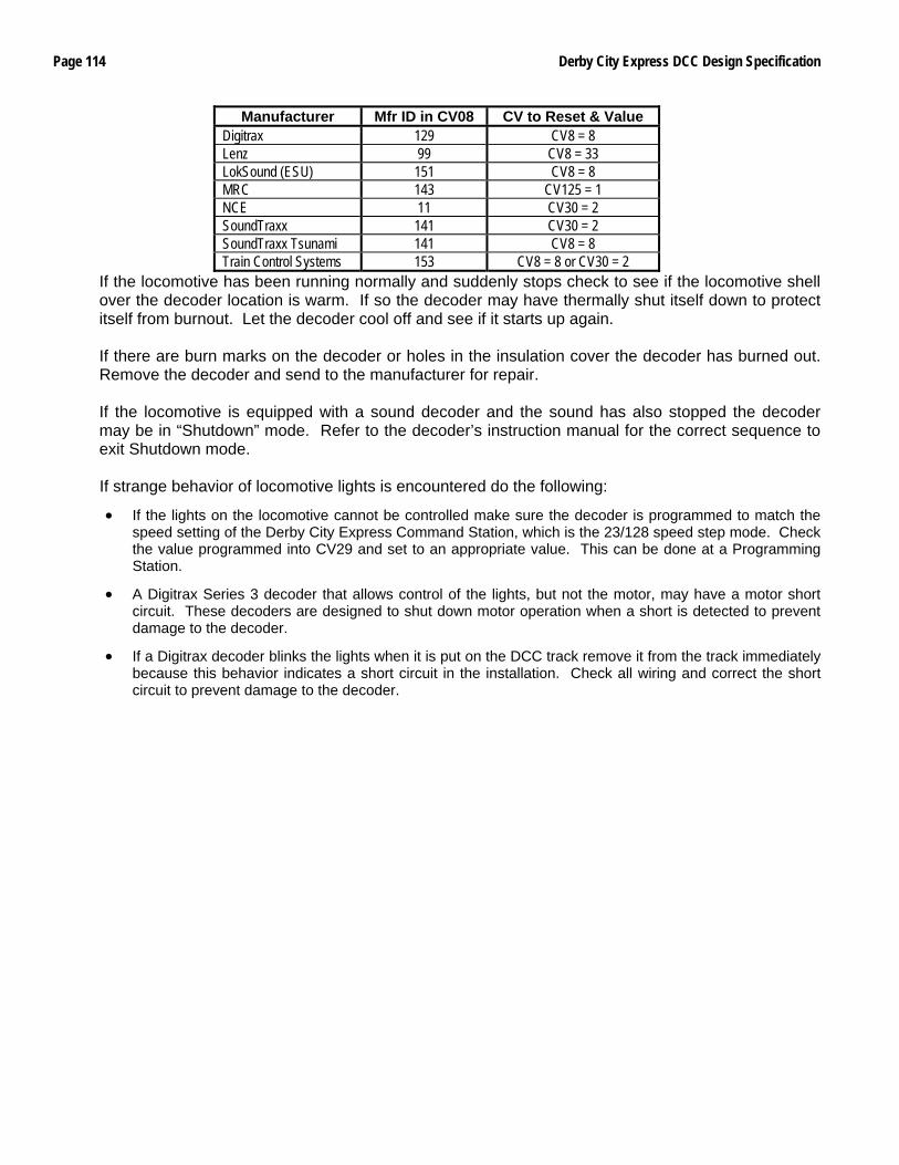
Page 114 Derby City Express DCC Design Specification
Manufacturer Mfr ID in CV08 CV to Reset & Value Digitrax 129 CV8 = 8 Lenz 99 CV8 = 33 LokSound (ESU) 151 CV8 = 8 MRC 143 CV125 = 1 NCE 11 CV30 = 2 SoundTraxx 141 CV30 = 2 SoundTraxx Tsunami 141 CV8 = 8 Train Control Systems 153 CV8 = 8 or CV30 = 2
If the locomotive has been running normally and suddenly stops check to see if the locomotive shell over the decoder location is warm. If so the decoder may have thermally shut itself down to protect itself from burnout. Let the decoder cool off and see if it starts up again. If there are burn marks on the decoder or holes in the insulation cover the decoder has burned out. Remove the decoder and send to the manufacturer for repair. If the locomotive is equipped with a sound decoder and the sound has also stopped the decoder may be in “Shutdown” mode. Refer to the decoder’s instruction manual for the correct sequence to exit Shutdown mode. If strange behavior of locomotive lights is encountered do the following:
• If the lights on the locomotive cannot be controlled make sure the decoder is programmed to match the speed setting of the Derby City Express Command Station, which is the 23/128 speed step mode. Check the value programmed into CV29 and set to an appropriate value. This can be done at a Programming Station.
• A Digitrax Series 3 decoder that allows control of the lights, but not the motor, may have a motor short circuit. These decoders are designed to shut down motor operation when a short is detected to prevent damage to the decoder.
• If a Digitrax decoder blinks the lights when it is put on the DCC track remove it from the track immediately because this behavior indicates a short circuit in the installation. Check all wiring and correct the short circuit to prevent damage to the decoder.