Embed Size (px)
Citation preview
Installation Guide
*353109*
SAFETY INFORMATION
This instruction booklet is written for qualified, fac-tory-trained technicians who are already familiarwith the use of Evinrude®/Johnson® Special Tools.This booklet is not a substitute for work experi-ence. It is an organized guide for installation of theI-Command digital system.
This booklet uses the following signal words iden-tifying important safety messages.
IMPORTANT: Identifies information that will helpprevent damage to machinery and appears nextto information that controls correct assembly andoperation of the product.
These safety alert signal words mean:ATTENTION!BECOME ALERT!YOUR SAFETY IS INVOLVED!
Always follow common shop safety practices. Ifyou have not had training related to common shopsafety practices, you should do so to protect your-self, as well as the people around you.
It is understood that this booklet may be trans-lated into other languages. In the event of any dis-crepancy, the English version shall prevail.
DO NOT perform any installation until you haveread the instructions and checked the picturesrelating to the installation procedures.
Be careful, and never rush or guess a service pro-cedure. Human error is caused by many factors:carelessness, fatigue, overload, preoccupation,unfamiliarity with the product, and drugs and alco-hol use, to name a few. Damage to a boat andoutboard can be fixed in a short period of time, butinjury or death has a lasting effect.
When replacement parts are required, useEvinrude/Johnson Genuine Parts or parts withequivalent characteristics, including type, strengthand material. Using substandard parts could resultin injury or product malfunction.
Torque wrench tightening specifications must bestrictly followed. Replace any locking fastener(locknut or patch screw) if its locking featurebecomes weak. Definite resistance to turningmust be felt when reusing a locking fastener. Ifreplacement is specified or required because thelocking fastener has become weak, use onlyauthorized Evinrude/Johnson Genuine Parts.
If you use procedures or service tools that are notrecommended in this instruction booklet, YOUALONE must decide if your actions might injurepeople or damage the outboard.
DANGER
Indicates an imminently hazardous situa-tion which, if not avoided, WILL result indeath or serious injury.
WARNING
Indicates a potentially hazardous situationwhich, if not avoided, CAN result in severeinjury or death.
CAUTION
Indicates a potentially hazardous situationwhich, if not avoided, MAY result in minoror moderate personal injury or propertydamage. It also may be used to alertagainst unsafe practices.
The following trademarks are the property of Bombardier Recreational Products Inc. or its affiliates.Evinrude ® I-Command ™
Evinrude ® E-TEC ® Johnson ®
† NMEA 2000 is a registered trademark of the National Marine Electronics Association or its subsidiaries.
© 2006 BRP US Inc. All rights reserved.TM, ® Trademarks and registered trademarks of Bombardier Recreational Products Inc. or its affiliates.
I-COMMAND DIGITAL SYSTEMGENERAL INFORMATION
I-COMMAND DIGITAL SYSTEMIMPORTANT: This instruction booklet outlines the installation of the I-Command Digital Integrated Per-formance System. Service technicians should review this document and the I-Command Digital User’sGuide (P/N 352974 for 3-inch gauge; P/N 353150 for 2-inch gauge) before installing. (Installation instruc-tions and User’s Guides can be ordered through Evinrude/Johnson Genuine Parts or be downloadedfrom the I-Command section of the DealerPort website.)
GENERAL INFORMATIONThe I-Command Digital Integrated PerformanceSystem uses “plug and play” networking technol-ogy based on NMEA 2000† data communicationsstandards. These standards provide communica-tions through a serial data network utilizing a Con-troller Area Network (CAN) integrated circuit (IC).This network operates at 250 kb/second andallows multiple electronic devices to be connectedtogether on a common channel for easy informa-tion sharing.
I-Command digital displays are designed specifi-cally for NMEA 2000-certified Evinrude E-TECoutboards. The instruments provide enhanceddisplay of engine and boat performance informa-tion. Multiple functions are integrated into eachinstrument. Additional instruments and accesso-ries can be added with the “plug and play” design.
NMEA 2000 NetworkThe NMEA 2000 network provides a communica-tions link between two or more devices that trans-fer NMEA 2000 information. I-Command is aNMEA 2000 networking system developed for usewith Evinrude outboards.
The I-Command network allows multiple digitaldisplays to monitor and present engine data mes-sages such as RPM, temperature, water pres-sure, or engine hours, etc. Digital display units canbe used to monitor engine diagnostics and fuellevel(s).
An I-Command digital display installed with anEvinrude E-TEC outboard creates a NMEA 2000network. The connectors and cables of an I-Com-mand digital system pass information from theengine along the network to the I-Command digi-tal display unit.
Each digital display and sensor attached to thenetwork can communicate with one another.Location, speed, and temperature can be shared.Other capabilities include the ability to monitor thefuel level in up to three fuel tanks, and displayingdetailed engine information such as oil level, fuelefficiency, and much more.
The I-Command Digital Integrated PerformanceSystem can be built onto a boat's existing networkby adding a T-connector and building a networkbackbone from that.
To assure proper system operation, the systemprogramming must be completed at the outboardand at the gauge. For the outboard, run theEvinrude Diagnostics program. Refer to EvinrudeDiagnostics for complete procedure. For finalgauge set-up, refer to the I-Command DigitalUser’s guide.
2
I-COMMAND DIGITAL SYSTEMGENERAL INFORMATION
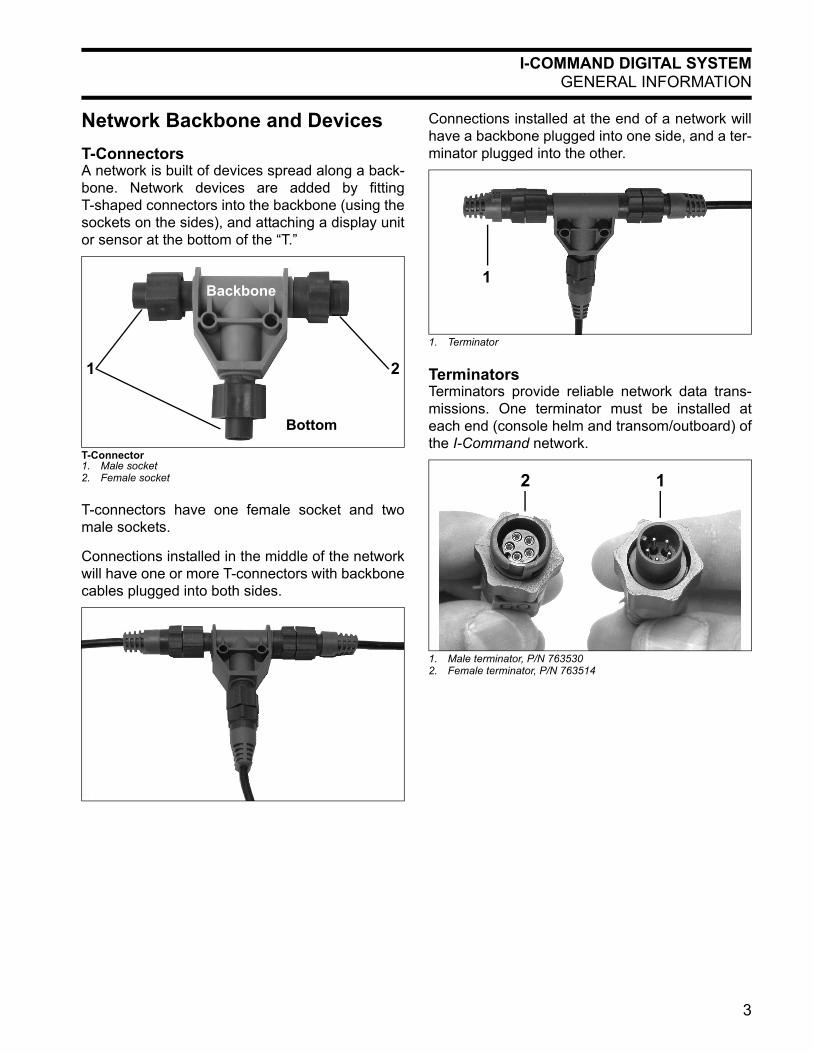
Network Backbone and DevicesT-ConnectorsA network is built of devices spread along a back-bone. Network devices are added by fittingT-shaped connectors into the backbone (using thesockets on the sides), and attaching a display unitor sensor at the bottom of the “T.”
T-connectors have one female socket and twomale sockets.
Connections installed in the middle of the networkwill have one or more T-connectors with backbonecables plugged into both sides.
Connections installed at the end of a network willhave a backbone plugged into one side, and a ter-minator plugged into the other.
TerminatorsTerminators provide reliable network data trans-missions. One terminator must be installed ateach end (console helm and transom/outboard) ofthe I-Command network.
T-Connector1. Male socket2. Female socket
Backbone
Bottom
1 2
1. Terminator
1. Male terminator, P/N 7635302. Female terminator, P/N 763514
1
12
3
I-COMMAND DIGITAL SYSTEMGENERAL INFORMATION
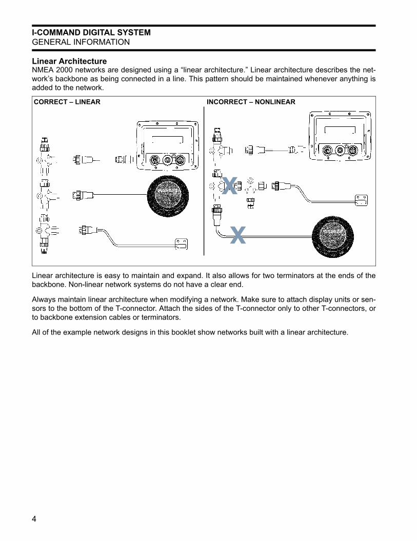
Linear ArchitectureNMEA 2000 networks are designed using a “linear architecture.” Linear architecture describes the net-work’s backbone as being connected in a line. This pattern should be maintained whenever anything isadded to the network.
Linear architecture is easy to maintain and expand. It also allows for two terminators at the ends of thebackbone. Non-linear network systems do not have a clear end.
Always maintain linear architecture when modifying a network. Make sure to attach display units or sen-sors to the bottom of the T-connector. Attach the sides of the T-connector only to other T-connectors, orto backbone extension cables or terminators.
All of the example network designs in this booklet show networks built with a linear architecture.
CORRECT – LINEAR INCORRECT – NONLINEAR
X
X
4
I-COMMAND DIGITAL SYSTEMBASIC NETWORK COMPONENTS
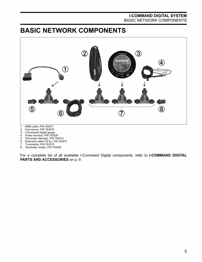
BASIC NETWORK COMPONENTS
For a complete list of all available I-Command Digital components, refer to I-COMMAND DIGITALPARTS AND ACCESSORIES on p. 9.
1. EMM cable, P/N 7635172. Fuel sensor, P/N 7636763. I-Command Digital gauge4. Power harness, P/N 7635295. Terminator (female), P/N 7635146. Extension cable (25 ft.), P/N 7635117. T-connector, P/N 7635128. Terminator (male), P/N 763530
1
56 7
8
2 3
4
5
I-COMMAND DIGITAL SYSTEMBACKBONE STRUCTURE
BACKBONE STRUCTURE
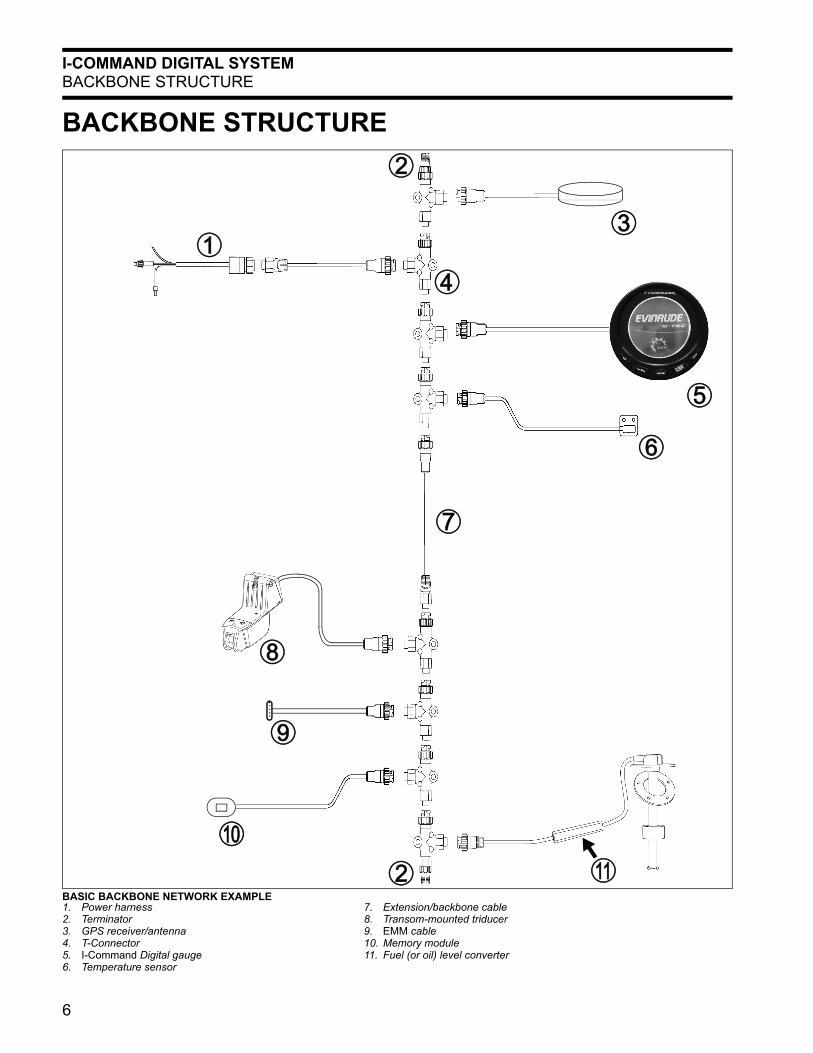
BASIC BACKBONE NETWORK EXAMPLE1. Power harness2. Terminator3. GPS receiver/antenna4. T-Connector5. I-Command Digital gauge6. Temperature sensor
7. Extension/backbone cable8. Transom-mounted triducer9. EMM cable10. Memory module11. Fuel (or oil) level converter
0
2
4
5
7
2
3
6
9
1
A
8
6
I-COMMAND DIGITAL SYSTEMNETWORK INSTALLATION
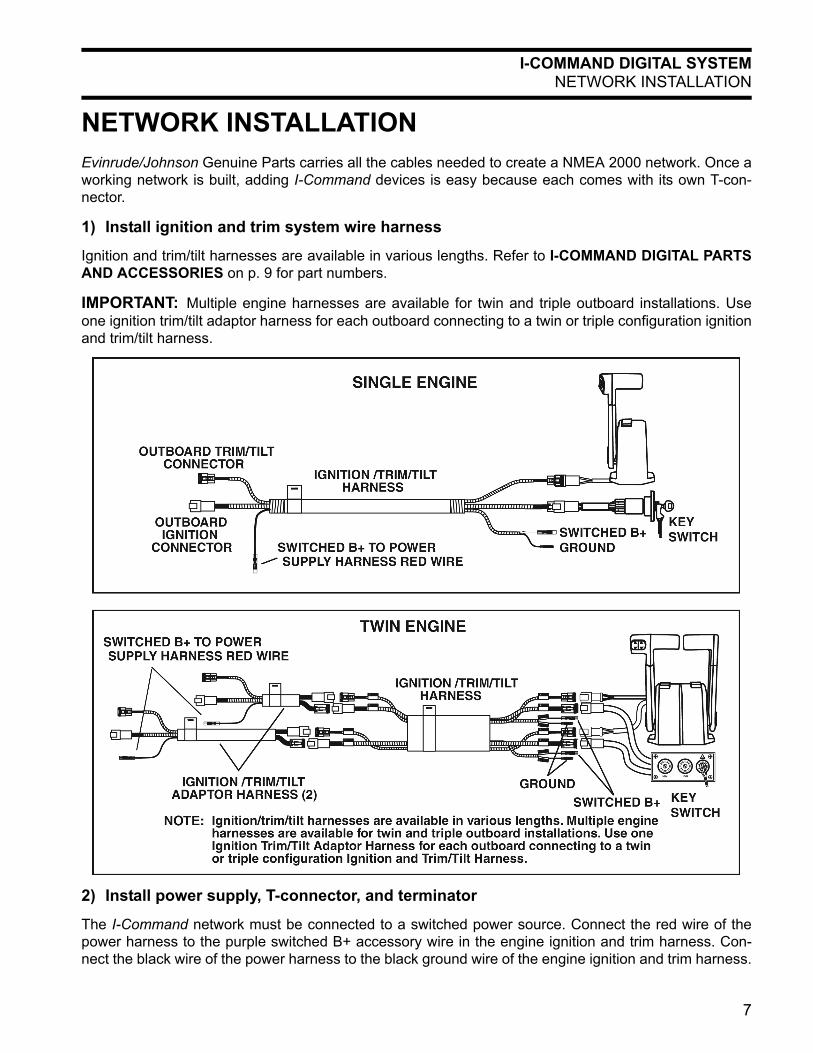
NETWORK INSTALLATIONEvinrude/Johnson Genuine Parts carries all the cables needed to create a NMEA 2000 network. Once aworking network is built, adding I-Command devices is easy because each comes with its own T-con-nector.
1) Install ignition and trim system wire harness
Ignition and trim/tilt harnesses are available in various lengths. Refer to I-COMMAND DIGITAL PARTSAND ACCESSORIES on p. 9 for part numbers.
IMPORTANT: Multiple engine harnesses are available for twin and triple outboard installations. Useone ignition trim/tilt adaptor harness for each outboard connecting to a twin or triple configuration ignitionand trim/tilt harness.
2) Install power supply, T-connector, and terminator
The I-Command network must be connected to a switched power source. Connect the red wire of thepower harness to the purple switched B+ accessory wire in the engine ignition and trim harness. Con-nect the black wire of the power harness to the black ground wire of the engine ignition and trim harness.
7
I-COMMAND DIGITAL SYSTEMNETWORK INSTALLATION
Connect the power harness twist-lock connectorto center point of T-connector. Connect a termina-tor to one end of the T-connector.
3) Install I-Command Digital gauge
Install the I-Command Digital gauge into the dash-board panel. Connect the twist lock connector tothe center point of the T-connector. Connect theT-connector to the next T-connector in the network(usually the Power harness T-connector).
3-inch and 2-inch gauges — Connect the digitalgauge yellow wire to the black wire of the warninghorn. Connect the blue wire of the digital gauge tothe red wire of the warning horn. Do not connectthe gauge white and black wires (these areunused).
4) Install fuel level sensor
The I-Command fuel level sensor converts thestandard analog electrical signal of the boats fuellevel sender to the NMEA 2000 signal.
Connect the fuel level sensor red wire to pink wireof boat fuel tank level sender. Connect the fuellevel sensor black wire to the black wire (ground)of the boat fuel tank sensor. Connect the fuel levelsensor connector to the center point of the T-con-nector.
5) Add an additional network device
Other devices, such as another I-Command Digi-tal gauge, an auxiliary fuel tank level sensor, or aGPS sensor can be added anywhere along thenetwork backbone.
Additions can be at the end of the network(between a T-connector and a terminator),between two T-connectors, or between a T-con-nector and a backbone extension cable.
To add a new device, separate the sockets of theold connection and attach the new T-connectorbetween them.
6) Connect extension cable
The I-Command network system offers extensioncables in various lengths. Every extension cablehas a male connector on one end and a femaleconnector on the other.
Connect the appropriate length extension cable tothe last T-connector at the helm console and routethe cable through the rigging tubes to the transomarea.
IMPORTANT: The maximum network backbonelength is 300 ft. (91 m).
Extension cables can also be attached between adevice on the network and a T-connector. Do notuse more than 15 ft. (4.6 m) of extension cablebetween a device and the network backbone.
7) Install the EMM cable, T-connector, andterminator
The I-Command network treats the outboard likeanother device.
Connect the 4-pin connector to the CANBus con-nector on the engine EMM. Connect the 15 ft. (4.6m) extension cable to the EMM cable and routethe cable along the path of the ignition and trimharness and into the boat.
Connect the extension cable to the center point ofa T-connector, then connect the remaining end ofthe T-connector to the extension cable from thehelm console.
Install a terminator to the end of the T-connector.
If installing multiple outboards, simply connect theremaining outboard EMM cable(s) to the nextT-connector in the line.
8) Check functionality
Complete the system programming at the out-board and at the gauge.
For the outboard, run the Evinrude Diagnosticsprogram and assign the outboard an identity forthe network. Refer to Evinrude Diagnostics forcomplete procedure. For the gauge, refer to theI-Command Digital User’s Guide.
8
I-COMMAND DIGITAL SYSTEMI-COMMAND DIGITAL PARTS AND ACCESSORIES
I-COMMAND DIGITAL PARTS AND ACCESSORIESDigital Displays• P/N 763507 — 3-inch multi-function tachometer and speedometer (recommend additional per engine)• P/N 763508 — 2-inch multi-function gauge (additional per requirement)• P/N 764640 — Chrome bezel 3-inch• P/N 764641 — Chrome bezel 2-inch
T-Connectors and Terminators• P/N 763512 — T-connector• P/N 763679 — Terminator kit
(includes female terminator, P/N 763514, and male terminator, P/N 763530)
Cables• P/N 763517 — Engine interface cable, 10 ft.• P/N 763528 — 1 ft. extension cable• P/N 763509 — 6 ft. extension cable• P/N 763510 — 15 ft. extension / backbone cable• P/N 763511 — 25 ft. extension / backbone cable
Accessories and Accessory Kits• P/N 763678 — Network power supply kit
(includes power cable, P/N 763529, and T-connector, P/N 763512)• P/N 763676 — Fuel level converter kit (per tank)
(includes fuel level converter, P/N 763515, and T-connector, P/N 763512)• P/N 763527 — GPS Antenna (requires T-connector, P/N 763512)• P/N 763704 — Memory Module kit
(includes T-connector, P/N 763512, and memory module, P/N 763703)• P/N 763677 — Sea water temp sensor kit
(includes sea water temp sensor, P/N 763516, and T-connector, P/N 763512)• P/N 5006214 — Water Pressure Sensor kit• P/N 763440 — Transom-mount triducer (depth, paddle wheel speed and sea water temperature)
Fuel Level Kits• P/N 763672 — Fuel level converter kit (main tank)• P/N 763673 — Fuel level converter kit (auxiliary tank)
Oil Level Kits• P/N 763578 — 1.8 gallon, single engine oil tank level kit• P/N 763579 — 3.0 gallon, single engine oil tank level kit• P/N 763580 — 1.8 gallon, twin engine oil tank level kit• P/N 763581 — 3.0 gallon, twin engine oil tank level kit• P/N 763582 — 3.0 gallon, triple engine oil tank level kit
Ignition Trim and Tilt HarnessesSingle Engine Triple Engine• P/N 763542 — 12 ft. • P/N 763545 — 25 ft. • P/N 763550 — 20 ft. • P/N 763551 — 25 ft.• P/N 763543 — 15 ft. • P/N 763546 — 28 ft.• P/N 763544 — 20 ft. Multiple Engine Adaptor Harness
• P/N 763552 — 6 ft. • P/N 763553 — 10 ft.Dual Engine• P/N 763547 — 15 ft. • P/N 763549 — 25 ft.• P/N 763548 — 20 ft.
9

10
Installation Guide
*353109*