Embed Size (px)
Citation preview
AGU Fall Meeting, December 2012, San Francisco
Differences between GPS receiver
antenna calibration models and influence on geodetic positioning
Q. Baire , W. Aerts, C. Bruyninx , E. Pottiaux and J. Legrand Royal Observatory of Belgium (ROB)
AGU Fall Meeting, December 2012, San Francisco
Outline
• Individual antenna calibration methods • Methodology
• Precise Point Positioning • Data sets
• Impact on computed station position • Summary and conclusions
AGU Fall Meeting, December 2012, San Francisco
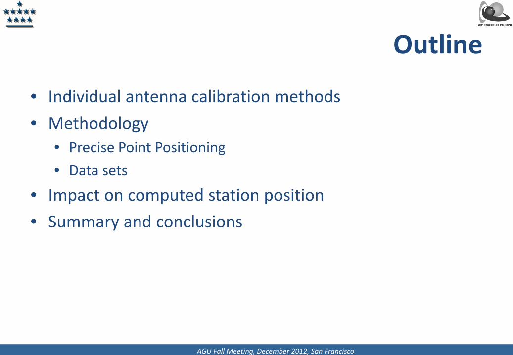
• Computed GPS station position: Antenna Reference Point (ARP) • GPS signal measured at the virtual phase center of the receiving antenna • Phase center corrections = Difference between ARP and phase center of the
antenna • Determined by the calibration and divided in 2 parts:
– Phase center offset (PCO): independent of satellite position – Phase center variation (PCV): depend on the azimuth and elevation of the satellite over
the antenna
PCC(α,z) = PCO + PCV(α,z)
Phase Center Correction (PCC)
ARP
PCO
PCV
Satellite
AGU Fall Meeting, December 2012, San Francisco
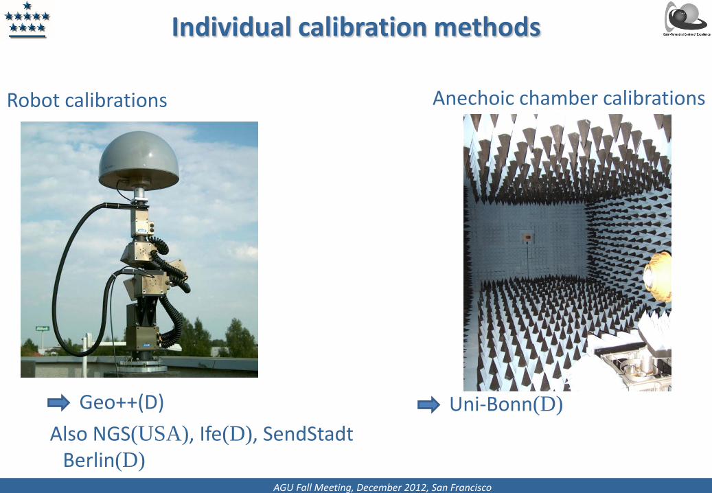
Anechoic chamber calibrations
Robot calibrations
Individual calibration methods
Geo++(D) Also NGS(USA), Ife(D), SendStadt
Berlin(D)
Uni-Bonn(D)
AGU Fall Meeting, December 2012, San Francisco
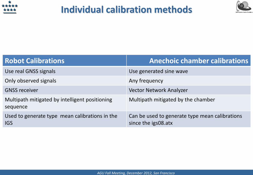
Individual calibration methods
Robot Calibrations Anechoic chamber calibrations Use real GNSS signals Use generated sine wave
Only observed signals Any frequency
GNSS receiver Vector Network Analyzer
Multipath mitigated by intelligent positioning sequence
Multipath mitigated by the chamber
Used to generate type mean calibrations in the IGS
Can be used to generate type mean calibrations since the igs08.atx
AGU Fall Meeting, December 2012, San Francisco
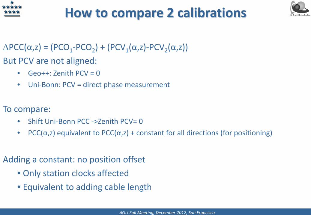
How to compare 2 calibrations
∆PCC(α,z) = (PCO1-PCO2) + (PCV1(α,z)-PCV2(α,z)) But PCV are not aligned:
• Geo++: Zenith PCV = 0 • Uni-Bonn: PCV = direct phase measurement
To compare: • Shift Uni-Bonn PCC ->Zenith PCV= 0 • PCC(α,z) equivalent to PCC(α,z) + constant for all directions (for positioning)
Adding a constant: no position offset
• Only station clocks affected • Equivalent to adding cable length
AGU Fall Meeting, December 2012, San Francisco
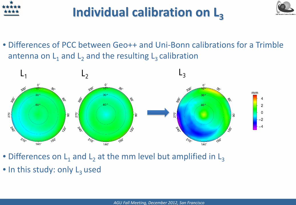
• Differences of PCC between Geo++ and Uni-Bonn calibrations for a Trimble antenna on L1 and L2 and the resulting L3 calibration
• Differences on L1 and L2 at the mm level but amplified in L3
• In this study: only L3 used
Individual calibration on L3
L1 L2 L3
AGU Fall Meeting, December 2012, San Francisco
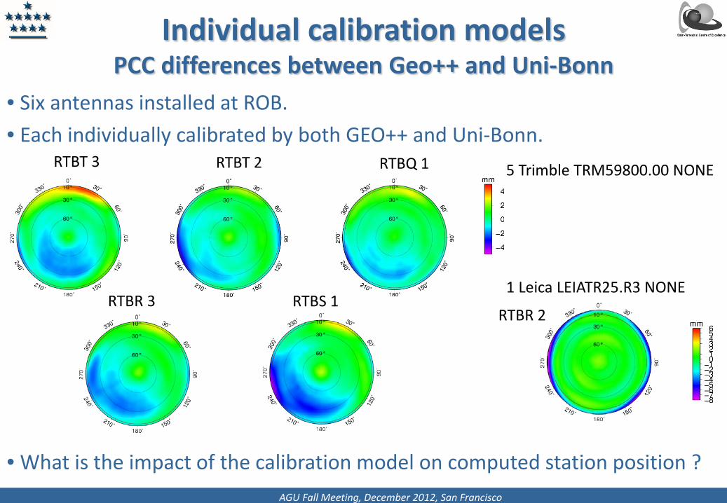
• Six antennas installed at ROB. • Each individually calibrated by both GEO++ and Uni-Bonn.
• What is the impact of the calibration model on computed station position ?
Individual calibration models PCC differences between Geo++ and Uni-Bonn
RTBT 2
RTBT 3
RTBQ 1
RTBR 3
RTBS 1
RTBR 2
5 Trimble TRM59800.00 NONE
1 Leica LEIATR25.R3 NONE
AGU Fall Meeting, December 2012, San Francisco
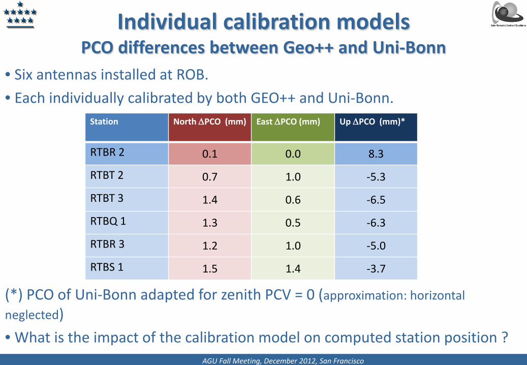
• Six antennas installed at ROB. • Each individually calibrated by both GEO++ and Uni-Bonn.
(*) PCO of Uni-Bonn adapted for zenith PCV = 0 (approximation: horizontal neglected) • What is the impact of the calibration model on computed station position ?
Individual calibration models PCO differences between Geo++ and Uni-Bonn
Station North ∆PCO (mm) East ∆PCO (mm) Up ∆PCO (mm)*
RTBR 2 0.1 0.0 8.3
RTBT 2 0.7 1.0 -5.3
RTBT 3 1.4 0.6 -6.5
RTBQ 1 1.3 0.5 -6.3
RTBR 3 1.2 1.0 -5.0
RTBS 1 1.5 1.4 -3.7
AGU Fall Meeting, December 2012, San Francisco
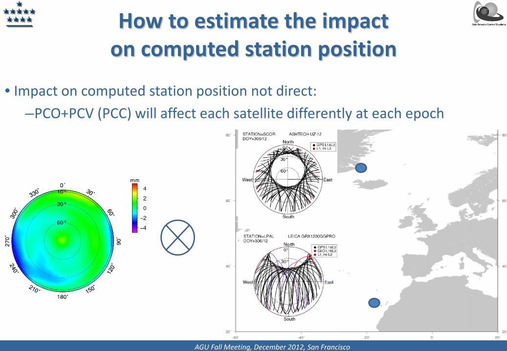
• Impact on computed station position not direct: –PCO+PCV (PCC) will affect each satellite differently at each epoch
How to estimate the impact on computed station position
AGU Fall Meeting, December 2012, San Francisco
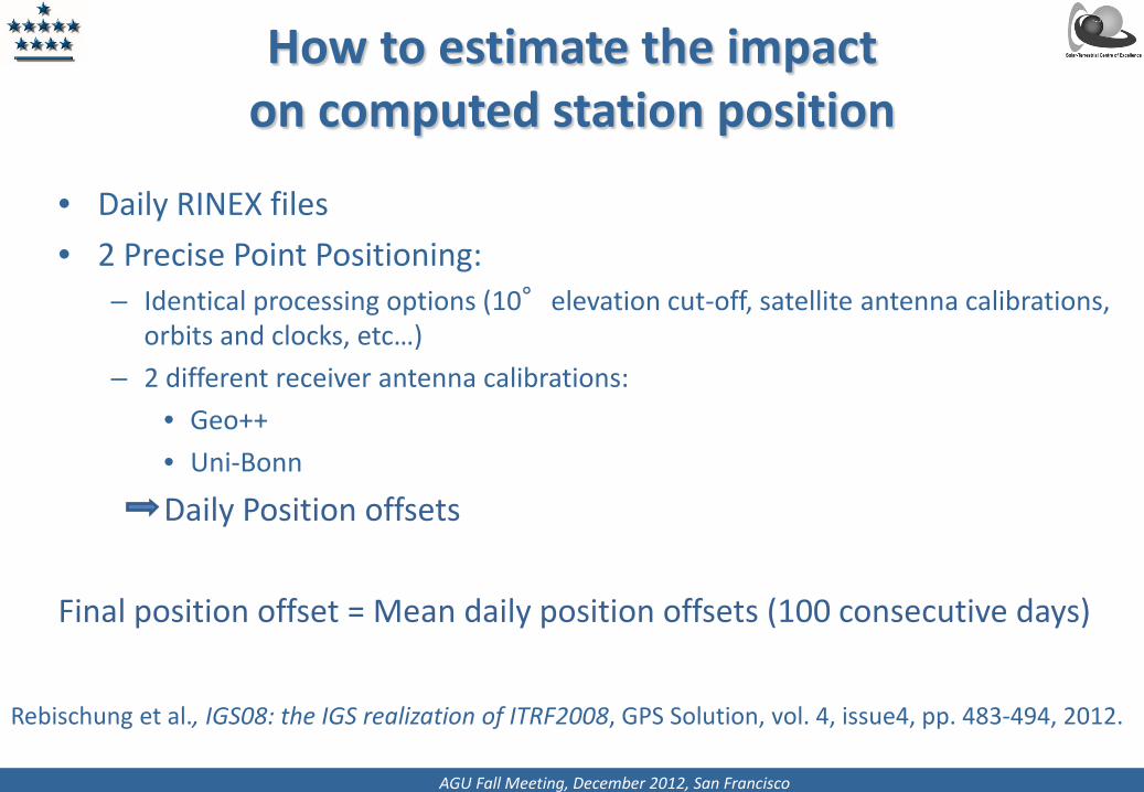
• Daily RINEX files • 2 Precise Point Positioning:
– Identical processing options (10°elevation cut-off, satellite antenna calibrations, orbits and clocks, etc…)
– 2 different receiver antenna calibrations: • Geo++ • Uni-Bonn
Daily Position offsets Final position offset = Mean daily position offsets (100 consecutive days)
How to estimate the impact on computed station position
Rebischung et al., IGS08: the IGS realization of ITRF2008, GPS Solution, vol. 4, issue4, pp. 483-494, 2012.
AGU Fall Meeting, December 2012, San Francisco
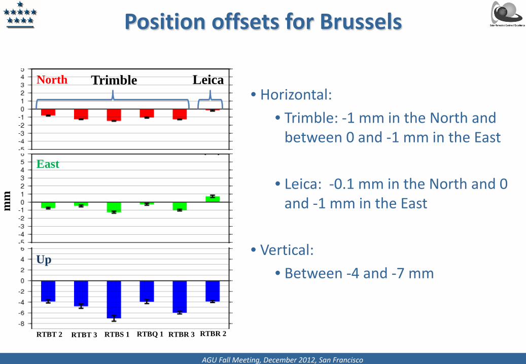
Position offsets for Brussels
• Horizontal: • Trimble: -1 mm in the North and
between 0 and -1 mm in the East • Leica: -0.1 mm in the North and 0
and -1 mm in the East
• Vertical: • Between -4 and -7 mm
mm
North
East
Up
Trimble
RTBT 2 RTBT 3 RTBS 1 RTBQ 1 RTBR 3 RTBR 2
Leica
AGU Fall Meeting, December 2012, San Francisco
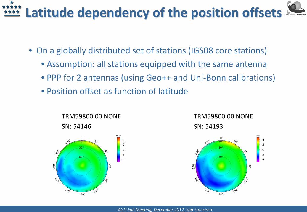
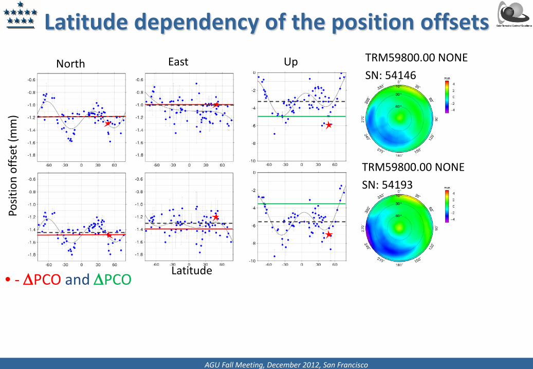
• On a globally distributed set of stations (IGS08 core stations) • Assumption: all stations equipped with the same antenna • PPP for 2 antennas (using Geo++ and Uni-Bonn calibrations) • Position offset as function of latitude
Latitude dependency of the position offsets
TRM59800.00 NONE SN: 54146
TRM59800.00 NONE SN: 54193
AGU Fall Meeting, December 2012, San Francisco
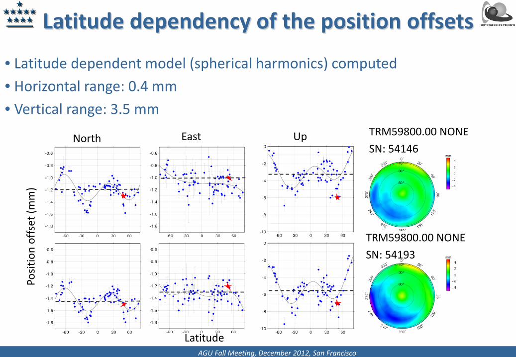
• Latitude dependent model (spherical harmonics) computed • Horizontal range: 0.4 mm • Vertical range: 3.5 mm
Latitude dependency of the position offsets
TRM59800.00 NONE SN: 54146
TRM59800.00 NONE SN: 54193
Latitude
North
East
Up
Posit
ion
offs
et (m
m)
AGU Fall Meeting, December 2012, San Francisco
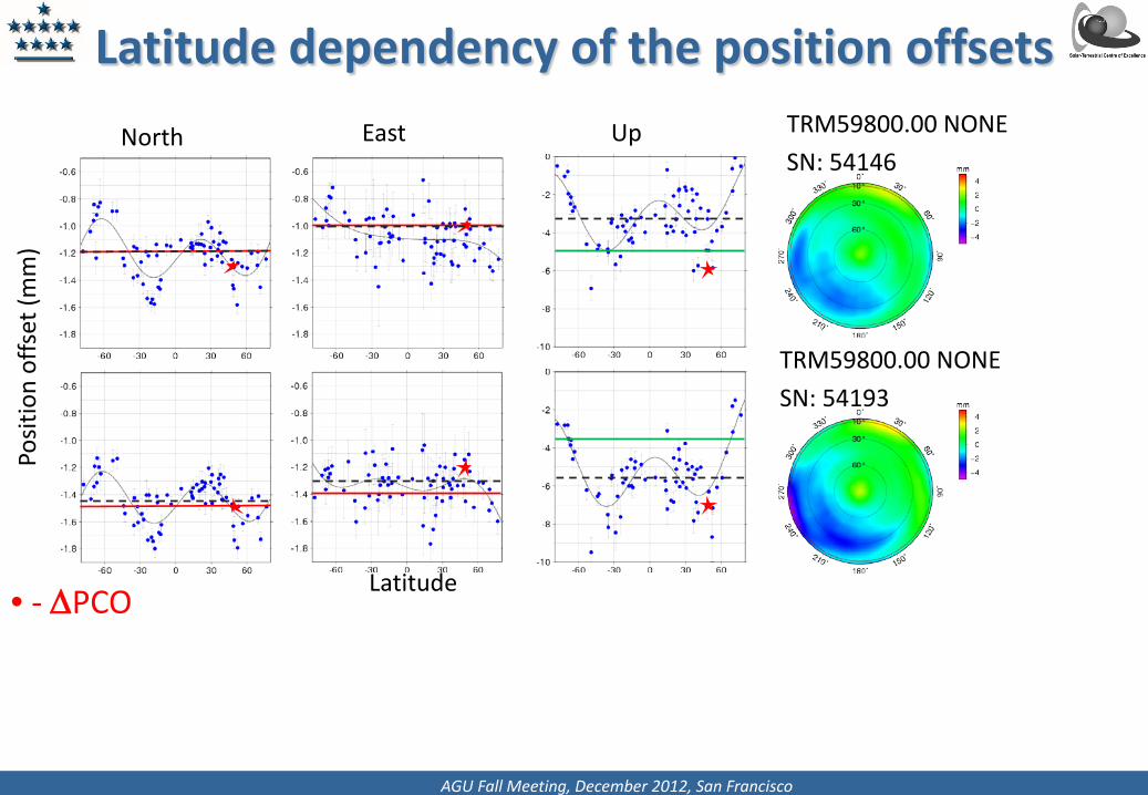
Latitude dependency of the position offsets
• - ∆PCO
TRM59800.00 NONE SN: 54146
TRM59800.00 NONE SN: 54193
Latitude
North
East
Up
Posit
ion
offs
et (m
m)
AGU Fall Meeting, December 2012, San Francisco
Latitude dependency of the position offsets
• - ∆PCO and ∆PCO
TRM59800.00 NONE SN: 54146
TRM59800.00 NONE SN: 54193
Latitude
North
East
Up
Posit
ion
offs
et (m
m)
AGU Fall Meeting, December 2012, San Francisco
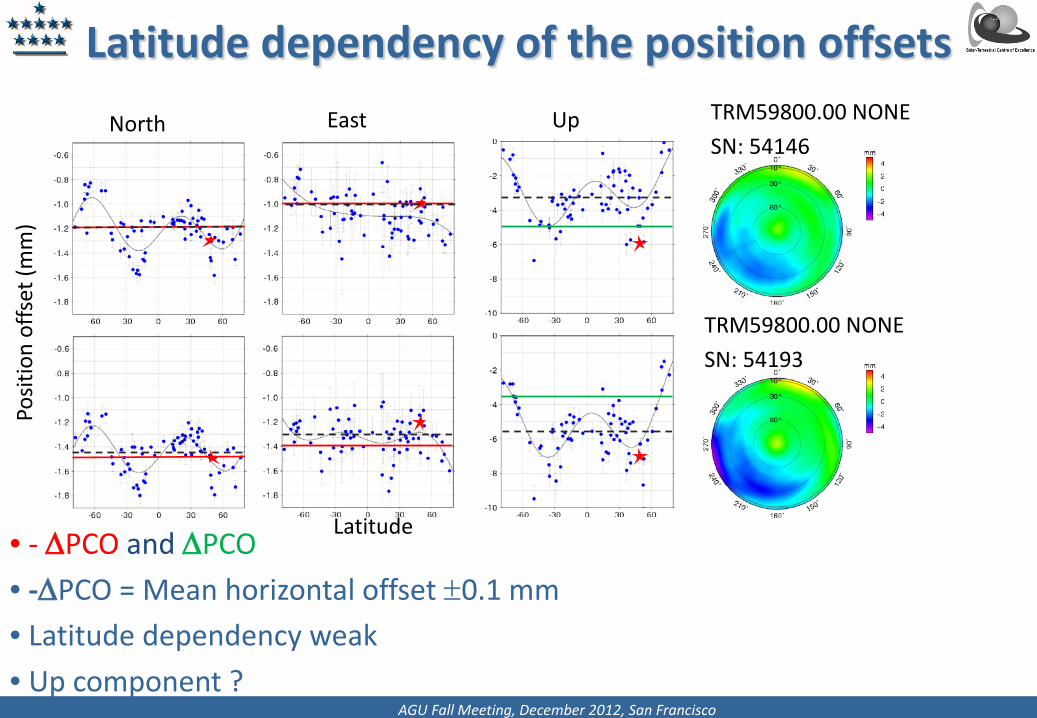
Latitude dependency of the position offsets
• - ∆PCO and ∆PCO • -∆PCO = Mean horizontal offset ±0.1 mm • Latitude dependency weak • Up component ?
TRM59800.00 NONE SN: 54146
TRM59800.00 NONE SN: 54193
Latitude
North
East
Up
Posit
ion
offs
et (m
m)
AGU Fall Meeting, December 2012, San Francisco
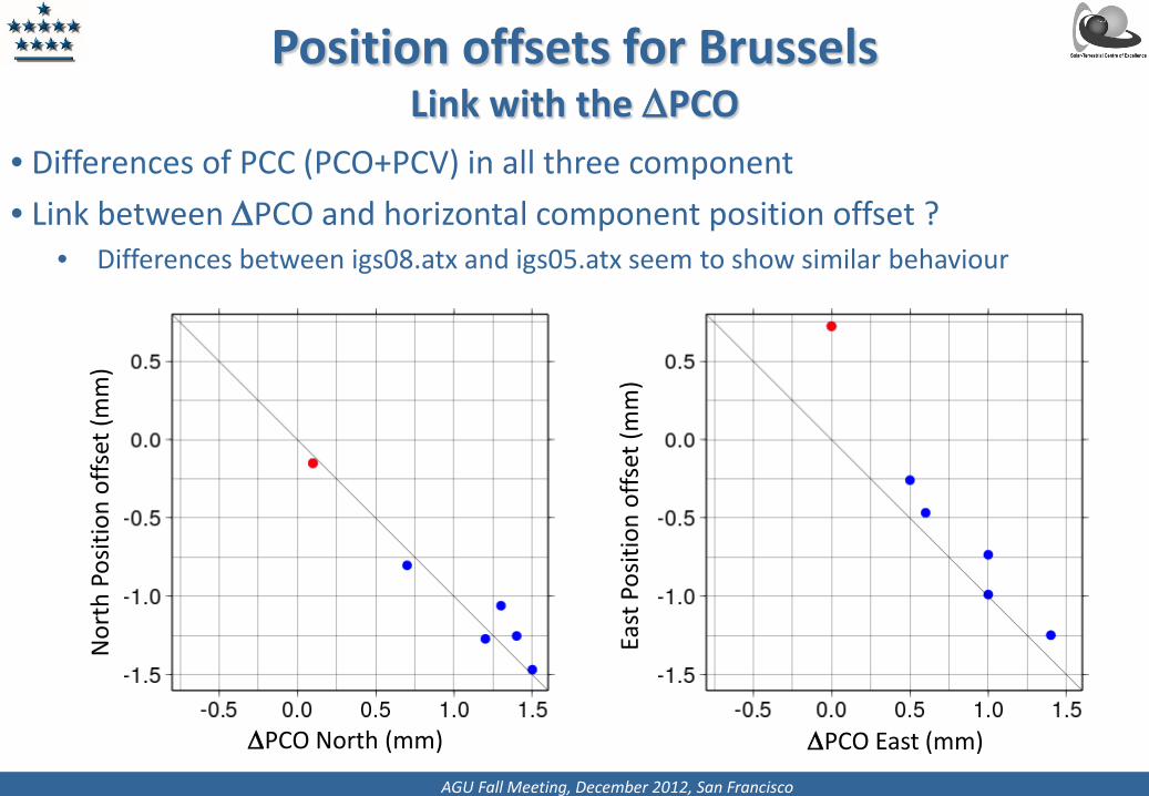
Position offsets for Brussels Link with the ∆PCO
• Differences of PCC (PCO+PCV) in all three component • Link between ∆PCO and horizontal component position offset ?
• Differences between igs08.atx and igs05.atx seem to show similar behaviour
∆PCO North (mm)
East
Pos
ition
offs
et (m
m)
Nor
th P
ositi
on o
ffset
(mm
)
∆PCO East (mm)
AGU Fall Meeting, December 2012, San Francisco
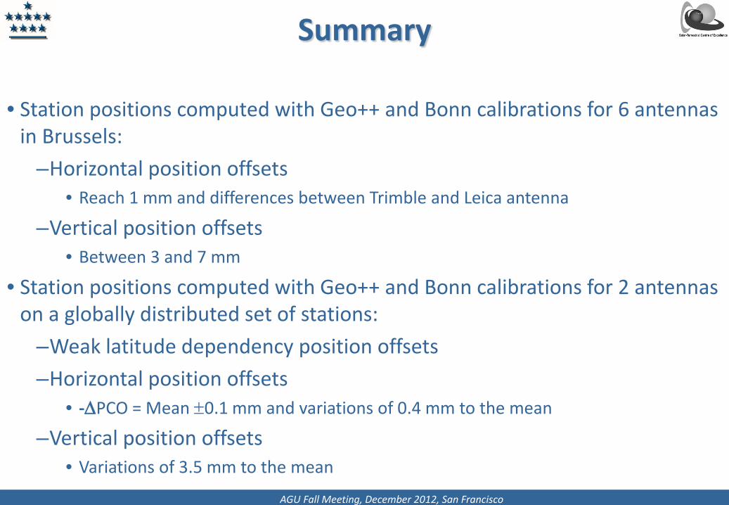
Summary
• Station positions computed with Geo++ and Bonn calibrations for 6 antennas in Brussels:
–Horizontal position offsets • Reach 1 mm and differences between Trimble and Leica antenna
–Vertical position offsets • Between 3 and 7 mm
• Station positions computed with Geo++ and Bonn calibrations for 2 antennas on a globally distributed set of stations:
–Weak latitude dependency position offsets –Horizontal position offsets
• -∆PCO = Mean ±0.1 mm and variations of 0.4 mm to the mean
–Vertical position offsets • Variations of 3.5 mm to the mean
AGU Fall Meeting, December 2012, San Francisco
Summary
• Impact of different calibration models on the computed station position not yet fully understood:
– Up component ?
– Which level of agreement to reach between receiver antenna calibrations for positioning ?