Embed Size (px)
Citation preview
From: S.O. Kasap, Optoelectronics and Photonics: Principles and Practices, Second Edition, © 2013 Pearson Education, USA 1
JF, SCO 1617
From: S.O. Kasap, Optoelectronics and Photonics: Principles and Practices, Second Edition, © 2013 Pearson Education, USA 1
JF, SCO 1617
Chapter 2 Dielectric Waveguides and Optical Fibers
Charles Kao, Nobel Laureate (2009)Courtesy of the Chinese University of Hong Kong
Dielectric waveguides
and
optical fibers
S.O. Kasap, Optoelectronics and Photonics: Principles and Practices, Second Edition, © 2013 Pearson Education© 2013 Pearson Education, Inc., Upper Saddle River, NJ. All rights reserved. This publication is prote cted by Copyright and written permission should be obtained from the
publisher prior to any prohibited reproduction, sto rage in a retrieval system, or transmission in any form or by any means, electronic, mechanical, photo copying, recording, or likewise. For information regarding permission(s), write to: Rights and Permissions Department, Pearso n Education, Inc., Upper Saddle River, NJ 07458.
14-Fev-2017
From: S.O. Kasap, Optoelectronics and Photonics: Principles and Practices, Second Edition, © 2013 Pearson Education, USA 2
JF, SCO 1617
From: S.O. Kasap, Optoelectronics and Photonics: Principles and Practices, Second Edition, © 2013 Pearson Education, USA 2
JF, SCO 1617
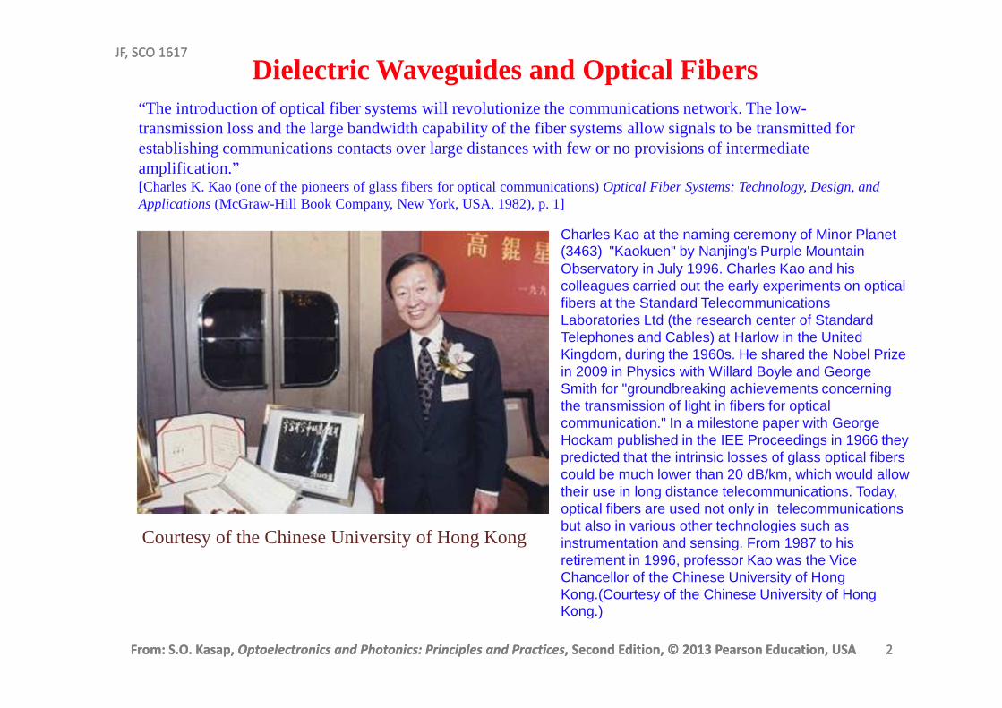
“The introduction of optical fiber systems will revolutionize the communications network. The low-transmission loss and the large bandwidth capability of the fiber systems allow signals to be transmitted for establishing communications contacts over large distances with few or no provisions of intermediate amplification.” [Charles K. Kao (one of the pioneers of glass fibers for optical communications) Optical Fiber Systems: Technology, Design, and Applications (McGraw-Hill Book Company, New York, USA, 1982), p. 1]
Dielectric Waveguides and Optical Fibers
Courtesy of the Chinese University of Hong Kong
Charles Kao at the naming ceremony of Minor Planet (3463) "Kaokuen" by Nanjing's Purple Mountain Observatory in July 1996. Charles Kao and his colleagues carried out the early experiments on optical fibers at the Standard Telecommunications Laboratories Ltd (the research center of Standard Telephones and Cables) at Harlow in the United Kingdom, during the 1960s. He shared the Nobel Prize in 2009 in Physics with Willard Boyle and George Smith for "groundbreaking achievements concerning the transmission of light in fibers for optical communication." In a milestone paper with George Hockam published in the IEE Proceedings in 1966 they predicted that the intrinsic losses of glass optical fibers could be much lower than 20 dB/km, which would allow their use in long distance telecommunications. Today, optical fibers are used not only in telecommunications but also in various other technologies such as instrumentation and sensing. From 1987 to his retirement in 1996, professor Kao was the Vice Chancellor of the Chinese University of Hong Kong.(Courtesy of the Chinese University of Hong Kong.)
From: S.O. Kasap, Optoelectronics and Photonics: Principles and Practices, Second Edition, © 2013 Pearson Education, USA 3
JF, SCO 1617
From: S.O. Kasap, Optoelectronics and Photonics: Principles and Practices, Second Edition, © 2013 Pearson Education, USA 3
JF, SCO 1617
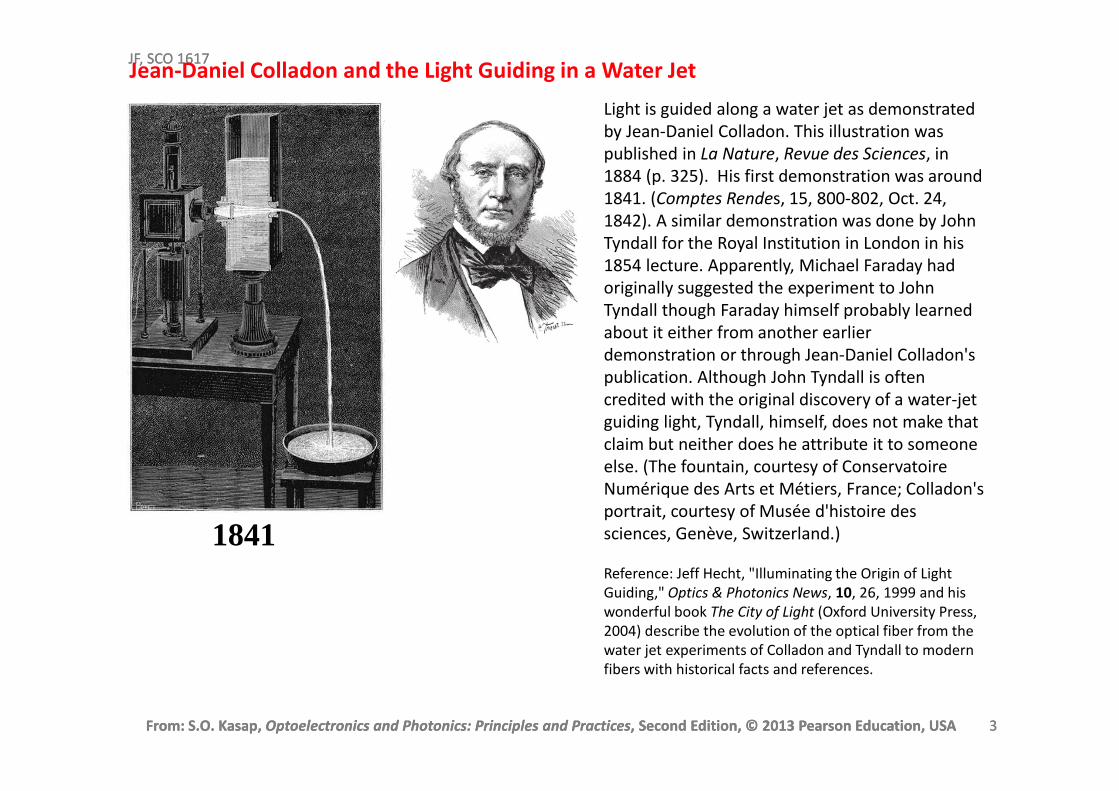
Light is guided along a water jet as demonstrated
by Jean-Daniel Colladon. This illustration was
published in La Nature, Revue des Sciences, in
1884 (p. 325). His first demonstration was around
1841. (Comptes Rendes, 15, 800-802, Oct. 24,
1842). A similar demonstration was done by John
Tyndall for the Royal Institution in London in his
1854 lecture. Apparently, Michael Faraday had
originally suggested the experiment to John
Tyndall though Faraday himself probably learned
about it either from another earlier
demonstration or through Jean-Daniel Colladon's
publication. Although John Tyndall is often
credited with the original discovery of a water-jet
guiding light, Tyndall, himself, does not make that
claim but neither does he attribute it to someone
else. (The fountain, courtesy of Conservatoire
Numérique des Arts et Métiers, France; Colladon's
portrait, courtesy of Musée d'histoire des
sciences, Genève, Switzerland.)
Reference: Jeff Hecht, "Illuminating the Origin of Light
Guiding," Optics & Photonics News, 10, 26, 1999 and his
wonderful book The City of Light (Oxford University Press,
2004) describe the evolution of the optical fiber from the
water jet experiments of Colladon and Tyndall to modern
fibers with historical facts and references.
1841
Jean-Daniel Colladon and the Light Guiding in a Water Jet
From: S.O. Kasap, Optoelectronics and Photonics: Principles and Practices, Second Edition, © 2013 Pearson Education, USA 4
JF, SCO 1617
From: S.O. Kasap, Optoelectronics and Photonics: Principles and Practices, Second Edition, © 2013 Pearson Education, USA 4
JF, SCO 1617
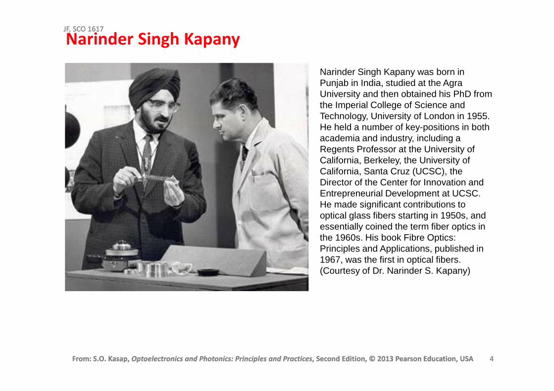
Narinder Singh Kapany
Narinder Singh Kapany was born in Punjab in India, studied at the Agra University and then obtained his PhD from the Imperial College of Science and Technology, University of London in 1955. He held a number of key-positions in both academia and industry, including a Regents Professor at the University of California, Berkeley, the University of California, Santa Cruz (UCSC), the Director of the Center for Innovation and Entrepreneurial Development at UCSC. He made significant contributions to optical glass fibers starting in 1950s, and essentially coined the term fiber optics in the 1960s. His book Fibre Optics: Principles and Applications, published in 1967, was the first in optical fibers. (Courtesy of Dr. Narinder S. Kapany)
From: S.O. Kasap, Optoelectronics and Photonics: Principles and Practices, Second Edition, © 2013 Pearson Education, USA 5
JF, SCO 1617
From: S.O. Kasap, Optoelectronics and Photonics: Principles and Practices, Second Edition, © 2013 Pearson Education, USA 5
JF, SCO 1617
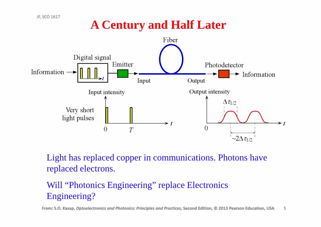
A Century and Half Later
Light has replaced copper in communications. Photons have replaced electrons.
Will “Photonics Engineering” replace Electronics Engineering?
From: S.O. Kasap, Optoelectronics and Photonics: Principles and Practices, Second Edition, © 2013 Pearson Education, USA 6
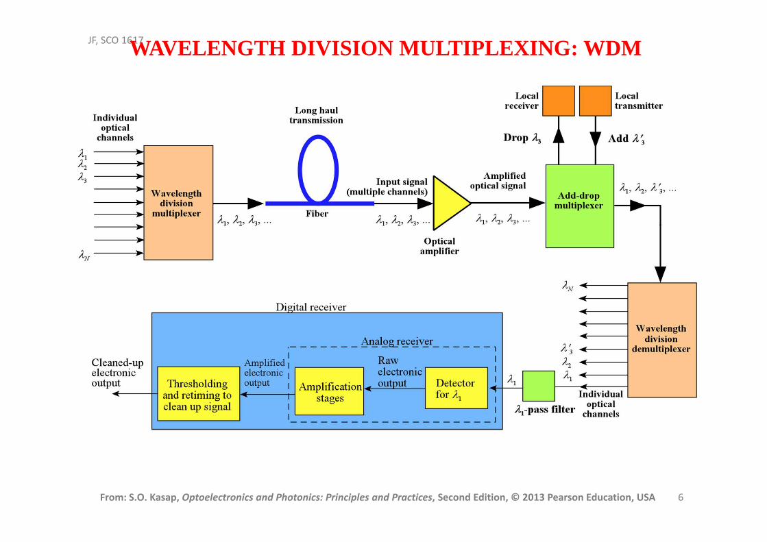
JF, SCO 1617WAVELENGTH DIVISION MULTIPLEXING: WDM
From: S.O. Kasap, Optoelectronics and Photonics: Principles and Practices, Second Edition, © 2013 Pearson Education, USA 7
JF, SCO 1617
From: S.O. Kasap, Optoelectronics and Photonics: Principles and Practices, Second Edition, © 2013 Pearson Education, USA 7
JF, SCO 1617
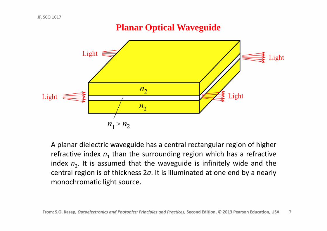
Planar Optical Waveguide
A planar dielectric waveguide has a central rectangular region of higher
refractive index n1 than the surrounding region which has a refractive
index n2. It is assumed that the waveguide is infinitely wide and the
central region is of thickness 2a. It is illuminated at one end by a nearly
monochromatic light source.
From: S.O. Kasap, Optoelectronics and Photonics: Principles and Practices, Second Edition, © 2013 Pearson Education, USA 8
JF, SCO 1617
From: S.O. Kasap, Optoelectronics and Photonics: Principles and Practices, Second Edition, © 2013 Pearson Education, USA 8
JF, SCO 1617
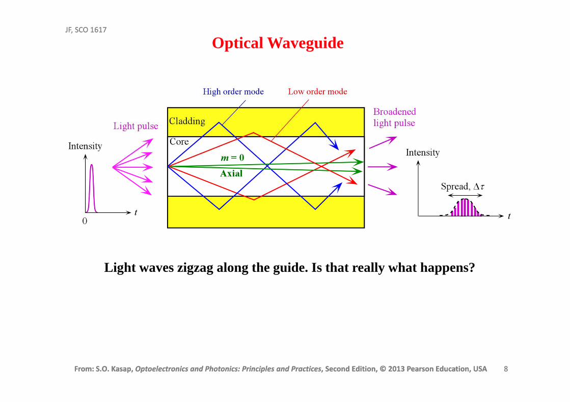
Light waves zigzag along the guide. Is that really what happens?
Optical Waveguide
From: S.O. Kasap, Optoelectronics and Photonics: Principles and Practices, Second Edition, © 2013 Pearson Education, USA 9
JF, SCO 1617
From: S.O. Kasap, Optoelectronics and Photonics: Principles and Practices, Second Edition, © 2013 Pearson Education, USA 9
JF, SCO 1617
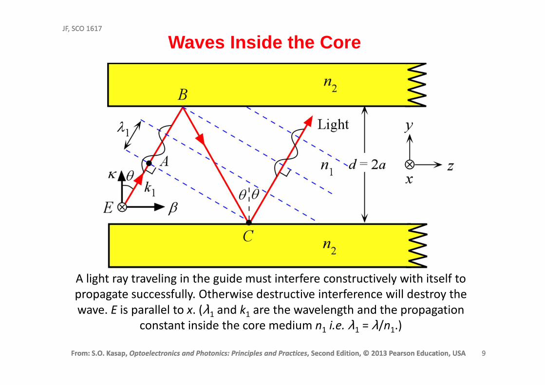
A light ray traveling in the guide must interfere constructively with itself to
propagate successfully. Otherwise destructive interference will destroy the
wave. E is parallel to x. (λ1 and k1 are the wavelength and the propagation
constant inside the core medium n1 i.e. λ1 = λ/n1.)
Waves Inside the Core
From: S.O. Kasap, Optoelectronics and Photonics: Principles and Practices, Second Edition, © 2013 Pearson Education, USA 10
JF, SCO 1617
From: S.O. Kasap, Optoelectronics and Photonics: Principles and Practices, Second Edition, © 2013 Pearson Education, USA 10
JF, SCO 1617
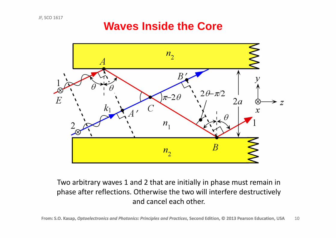
Two arbitrary waves 1 and 2 that are initially in phase must remain in
phase after reflections. Otherwise the two will interfere destructively
and cancel each other.
Waves Inside the Core
From: S.O. Kasap, Optoelectronics and Photonics: Principles and Practices, Second Edition, © 2013 Pearson Education, USA 11
JF, SCO 1617
From: S.O. Kasap, Optoelectronics and Photonics: Principles and Practices, Second Edition, © 2013 Pearson Education, USA 11
JF, SCO 1617
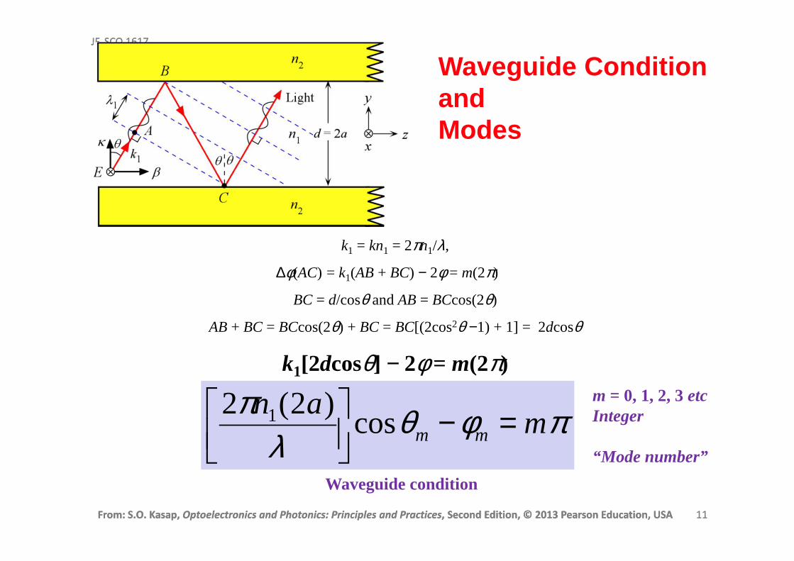
k1 = kn1 = 2πn1/λ,
∆φ(AC) = k1(AB + BC) − 2φ = m(2π)
BC = d/cosθ and AB = BCcos(2θ)
AB + BC = BCcos(2θ) + BC = BC[(2cos2θ −1) + 1] = 2dcosθ
k1[2dcosθ] − 2φ = m(2π)
Waveguide condition
πφθλ
πm
anmm =−
cos)2(2 1
Waveguide ConditionandModes
m = 0, 1, 2, 3 etcInteger
“Mode number”
From: S.O. Kasap, Optoelectronics and Photonics: Principles and Practices, Second Edition, © 2013 Pearson Education, USA 12
JF, SCO 1617
From: S.O. Kasap, Optoelectronics and Photonics: Principles and Practices, Second Edition, © 2013 Pearson Education, USA 12
JF, SCO 1617
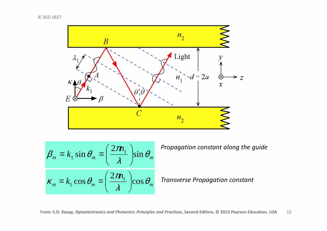
mmm
nk θ
λπθβ sin
2sin 1
1
==
mmm
nk θ
λπθκ cos
2cos 1
1
==
Propagation constant along the guide
Transverse Propagation constant
From: S.O. Kasap, Optoelectronics and Photonics: Principles and Practices, Second Edition, © 2013 Pearson Education, USA 13
JF, SCO 1617
From: S.O. Kasap, Optoelectronics and Photonics: Principles and Practices, Second Edition, © 2013 Pearson Education, USA 13
JF, SCO 1617
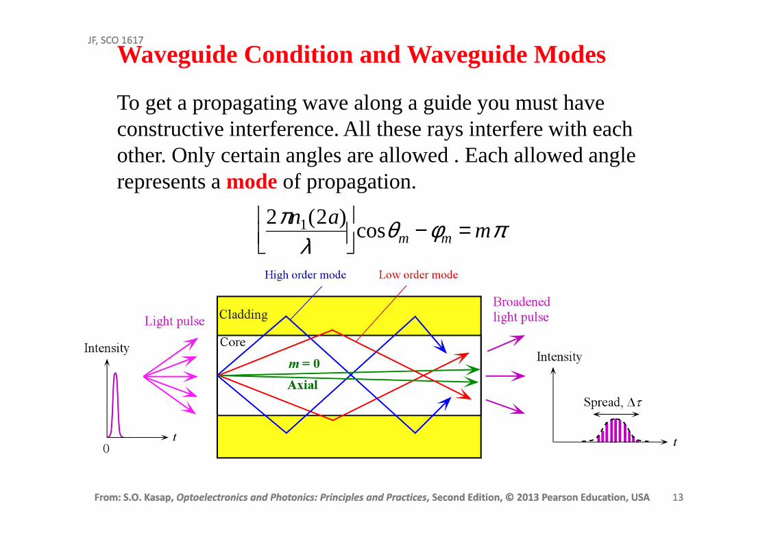
Waveguide Condition and Waveguide Modes
To get a propagating wave along a guide you must have constructive interference. All these rays interfere with each other. Only certain angles are allowed . Each allowed angle represents a mode of propagation.
2πn1(2a)λ
cosθm −φm = mπ
From: S.O. Kasap, Optoelectronics and Photonics: Principles and Practices, Second Edition, © 2013 Pearson Education, USA 14
JF, SCO 1617
From: S.O. Kasap, Optoelectronics and Photonics: Principles and Practices, Second Edition, © 2013 Pearson Education, USA 14
JF, SCO 1617
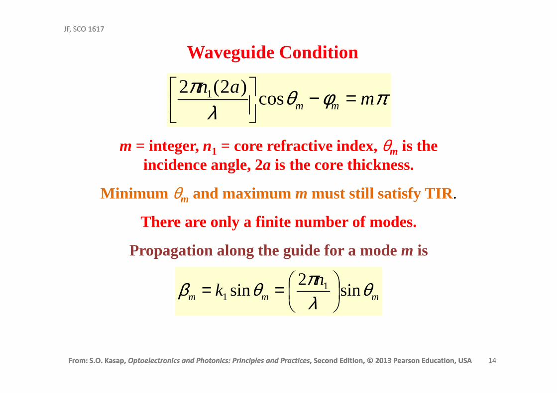
m = integer, n1 = core refractive index, θm is the incidence angle, 2a is the core thickness.
Minimum θm and maximum m must still satisfy TIR.
There are only a finite number of modes.
Propagation along the guide for a mode m is
mmm
nk θ
λπθβ sin
2sin 1
1
==
πφθλ
πm
anmm =−
cos)2(2 1
Waveguide Condition
From: S.O. Kasap, Optoelectronics and Photonics: Principles and Practices, Second Edition, © 2013 Pearson Education, USA 15
JF, SCO 1617
From: S.O. Kasap, Optoelectronics and Photonics: Principles and Practices, Second Edition, © 2013 Pearson Education, USA 15
JF, SCO 1617
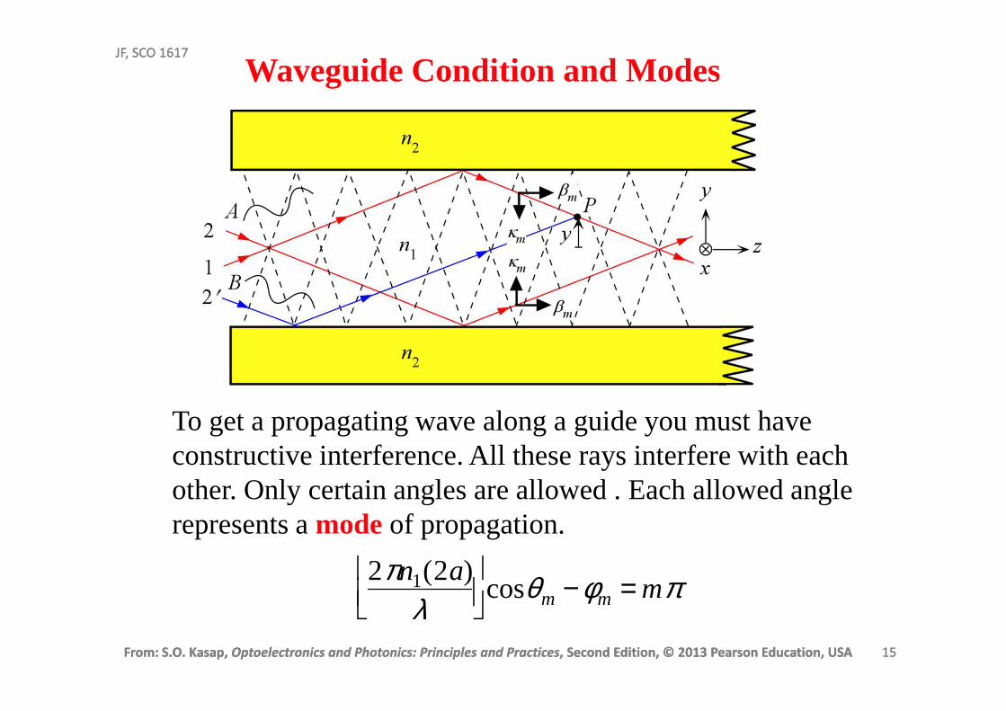
Waveguide Condition and Modes
To get a propagating wave along a guide you must have constructive interference. All these rays interfere with each other. Only certain angles are allowed . Each allowed angle represents a mode of propagation.
2πn1(2a)λ
cosθm −φm = mπ
From: S.O. Kasap, Optoelectronics and Photonics: Principles and Practices, Second Edition, © 2013 Pearson Education, USA 16
JF, SCO 1617
From: S.O. Kasap, Optoelectronics and Photonics: Principles and Practices, Second Edition, © 2013 Pearson Education, USA 16
JF, SCO 1617
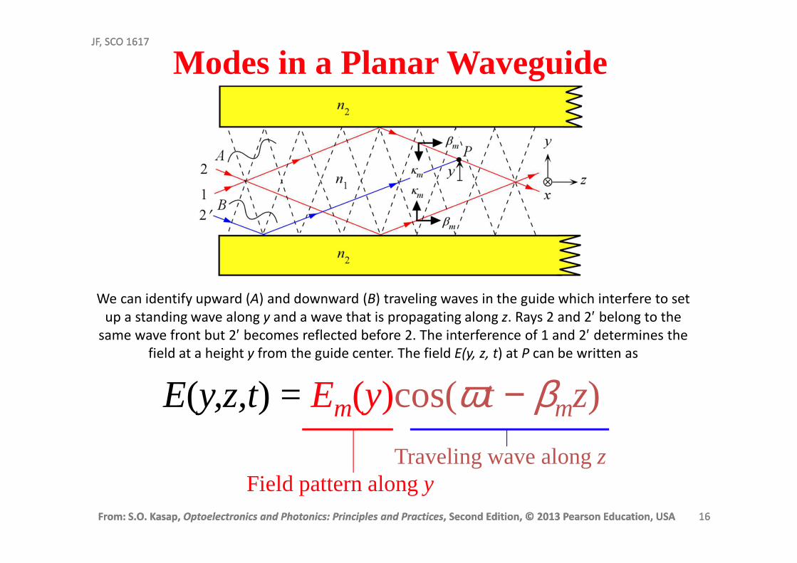
Modes in a Planar Waveguide
E(y,z,t) = Em(y)cos(ωt − βmz)
Traveling wave along zField pattern alongy
We can identify upward (A) and downward (B) traveling waves in the guide which interfere to set
up a standing wave along y and a wave that is propagating along z. Rays 2 and 2′ belong to the
same wave front but 2′ becomes reflected before 2. The interference of 1 and 2′ determines the
field at a height y from the guide center. The field E(y, z, t) at P can be written as
From: S.O. Kasap, Optoelectronics and Photonics: Principles and Practices, Second Edition, © 2013 Pearson Education, USA 17
JF, SCO 1617
From: S.O. Kasap, Optoelectronics and Photonics: Principles and Practices, Second Edition, © 2013 Pearson Education, USA 17
JF, SCO 1617
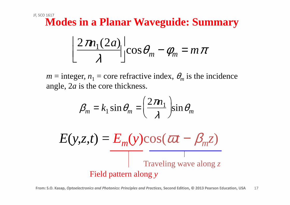
m = integer, n1 = core refractive index, θm is the incidence angle, 2a is the core thickness.
βm = k1sinθm = 2πn1
λ
sinθm
2πn1(2a)λ
cosθm −φm = mπ
Modes in a Planar Waveguide: Summary
E(y,z,t) = Em(y)cos(ωt − βmz)
Traveling wave along zField pattern alongy
From: S.O. Kasap, Optoelectronics and Photonics: Principles and Practices, Second Edition, © 2013 Pearson Education, USA 18
JF, SCO 1617
From: S.O. Kasap, Optoelectronics and Photonics: Principles and Practices, Second Edition, © 2013 Pearson Education, USA 18
JF, SCO 1617
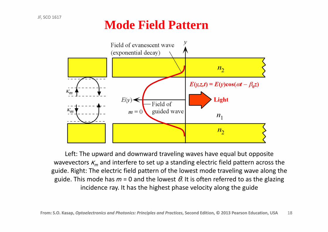
Left: The upward and downward traveling waves have equal but opposite
wavevectors κm and interfere to set up a standing electric field pattern across the
guide. Right: The electric field pattern of the lowest mode traveling wave along the
guide. This mode has m = 0 and the lowest θ. It is often referred to as the glazing
incidence ray. It has the highest phase velocity along the guide
Mode Field Pattern
From: S.O. Kasap, Optoelectronics and Photonics: Principles and Practices, Second Edition, © 2013 Pearson Education, USA 19
JF, SCO 1617
From: S.O. Kasap, Optoelectronics and Photonics: Principles and Practices, Second Edition, © 2013 Pearson Education, USA 19
JF, SCO 1617
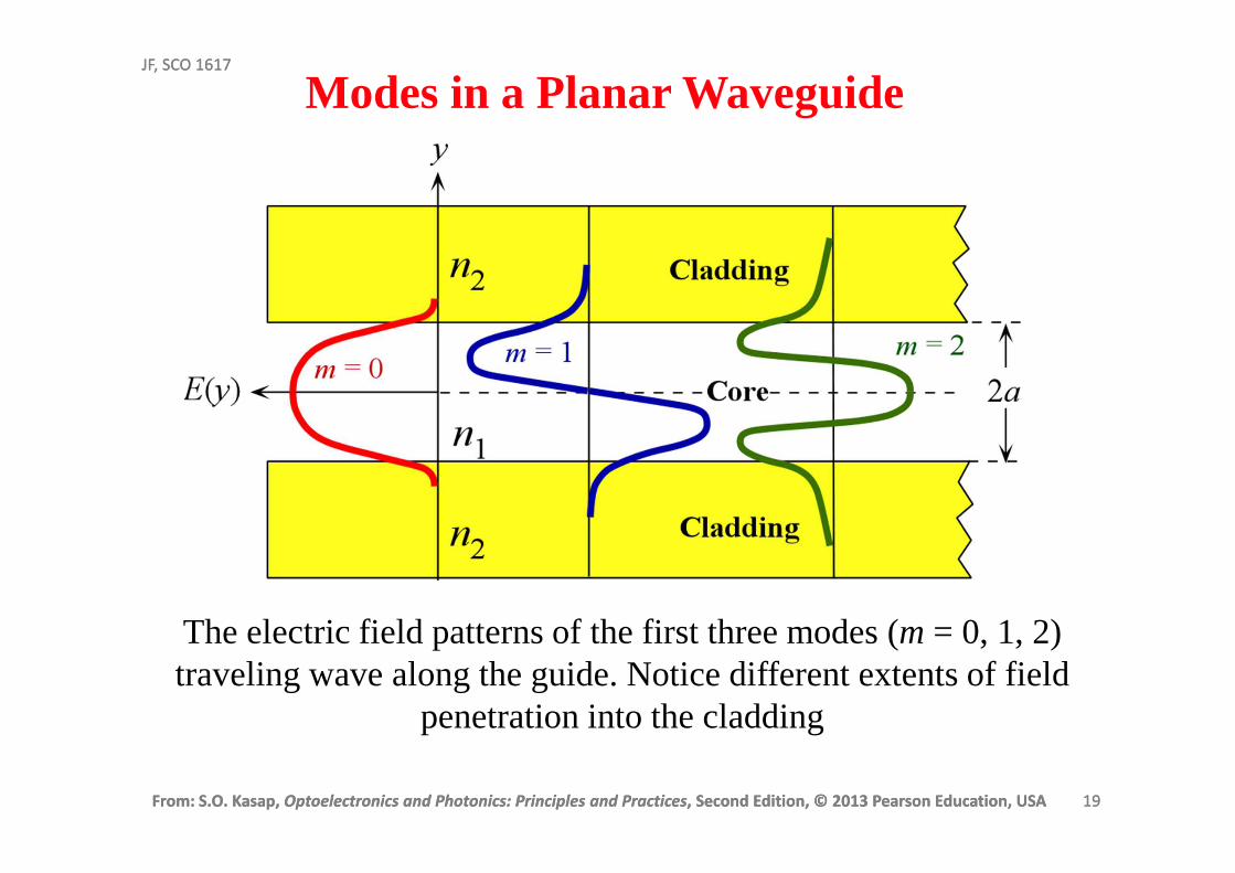
The electric field patterns of the first three modes (m = 0, 1, 2) traveling wave along the guide. Notice different extents of field
penetration into the cladding
Modes in a Planar Waveguide
From: S.O. Kasap, Optoelectronics and Photonics: Principles and Practices, Second Edition, © 2013 Pearson Education, USA 20
JF, SCO 1617
From: S.O. Kasap, Optoelectronics and Photonics: Principles and Practices, Second Edition, © 2013 Pearson Education, USA 20
JF, SCO 1617
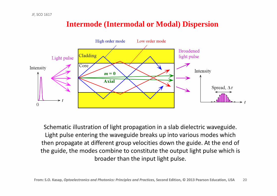
Intermode (Intermodal or Modal) Dispersion
Schematic illustration of light propagation in a slab dielectric waveguide.
Light pulse entering the waveguide breaks up into various modes which
then propagate at different group velocities down the guide. At the end of
the guide, the modes combine to constitute the output light pulse which is
broader than the input light pulse.
From: S.O. Kasap, Optoelectronics and Photonics: Principles and Practices, Second Edition, © 2013 Pearson Education, USA 21
JF, SCO 1617
From: S.O. Kasap, Optoelectronics and Photonics: Principles and Practices, Second Edition, © 2013 Pearson Education, USA 21
JF, SCO 1617
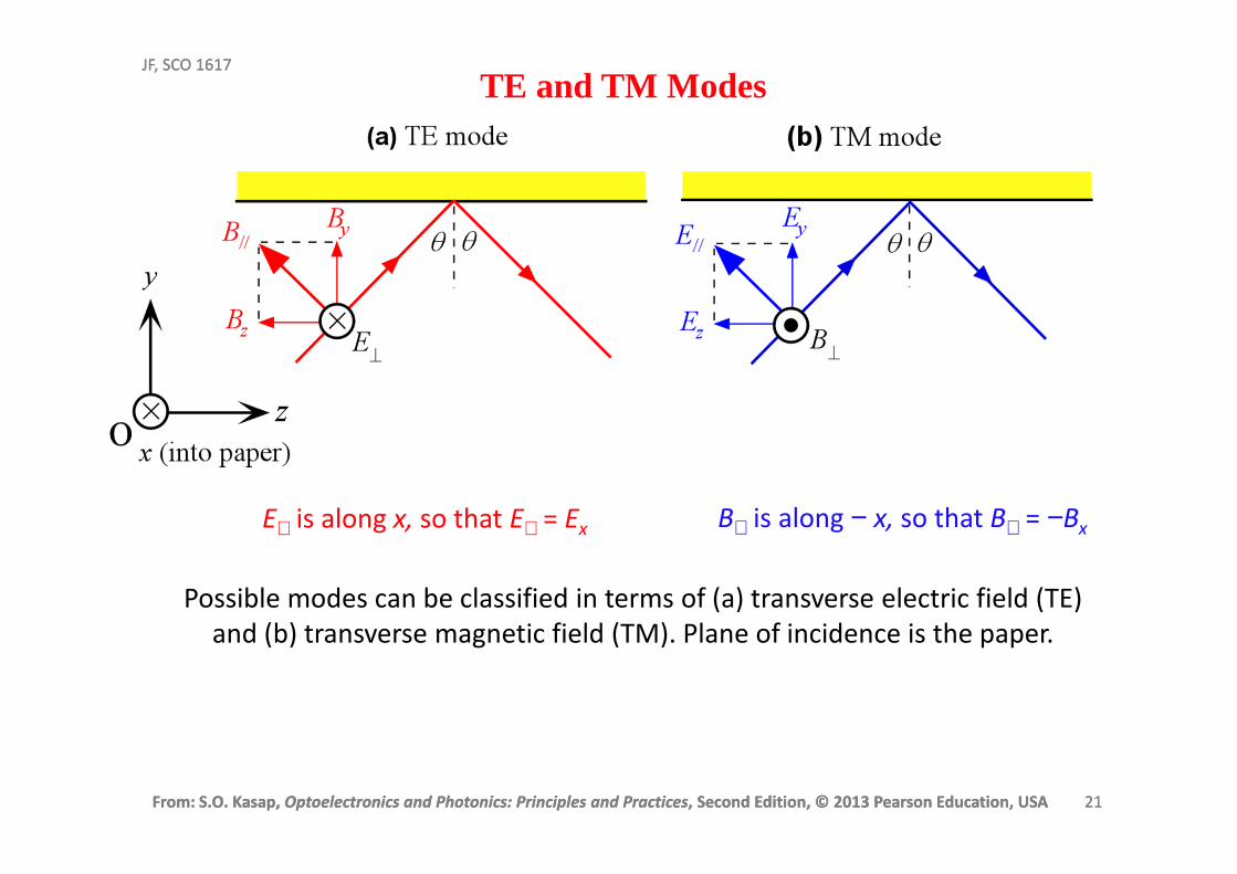
TE and TM Modes
Possible modes can be classified in terms of (a) transverse electric field (TE)
and (b) transverse magnetic field (TM). Plane of incidence is the paper.
B⊥ is along − x, so that B⊥ = −BxE⊥ is along x, so that E⊥ = Ex
From: S.O. Kasap, Optoelectronics and Photonics: Principles and Practices, Second Edition, © 2013 Pearson Education, USA 22
JF, SCO 1617
From: S.O. Kasap, Optoelectronics and Photonics: Principles and Practices, Second Edition, © 2013 Pearson Education, USA 22
JF, SCO 1617
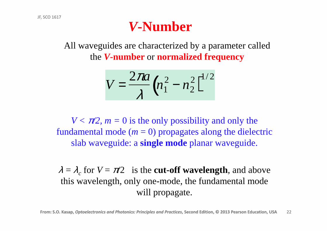
V-NumberAll waveguides are characterized by a parameter called
the V-number or normalized frequency
V = 2πa
λn1
2 − n22( )1/ 2
V < π/2, m = 0 is the only possibility and only the fundamental mode (m = 0) propagates along the dielectric
slab waveguide: asingle mode planar waveguide.
λ = λc for V = π/2 is the cut-off wavelength, and above this wavelength, only one-mode, the fundamental mode
will propagate.
From: S.O. Kasap, Optoelectronics and Photonics: Principles and Practices, Second Edition, © 2013 Pearson Education, USA 23
JF, SCO 1617
From: S.O. Kasap, Optoelectronics and Photonics: Principles and Practices, Second Edition, © 2013 Pearson Education, USA 23
JF, SCO 1617
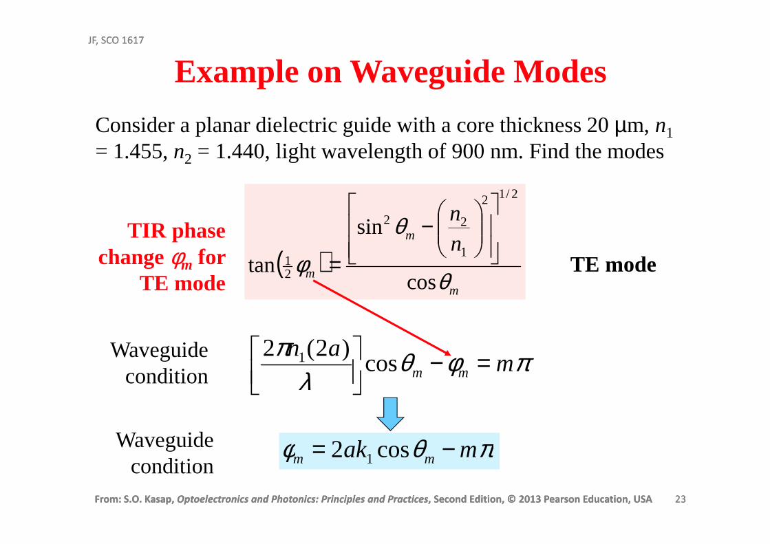
Example on Waveguide Modes
Consider a planar dielectric guide with a core thickness 20 µm, n1
= 1.455, n2 = 1.440, light wavelength of 900 nm. Find the modes
( )m
m
m
nn
θ
θ
φcos
sin
tan
2/12
1
22
21
−
=
πφθλ
πm
anmm =−
cos)2(2 1Waveguide
condition
TIR phase change φm for
TE mode
Waveguidecondition
TE mode
πθφ mak mm −= cos2 1
From: S.O. Kasap, Optoelectronics and Photonics: Principles and Practices, Second Edition, © 2013 Pearson Education, USA 24
JF, SCO 1617
From: S.O. Kasap, Optoelectronics and Photonics: Principles and Practices, Second Edition, © 2013 Pearson Education, USA 24
JF, SCO 1617
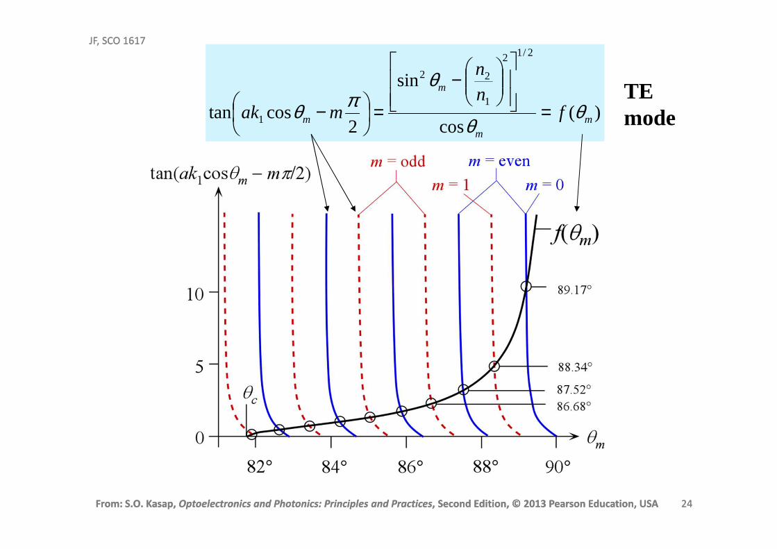
)(cos
sin
2costan
2/12
1
22
1 mm
m
m fnn
mak θθ
θπθ =
−
=
−TE mode
From: S.O. Kasap, Optoelectronics and Photonics: Principles and Practices, Second Edition, © 2013 Pearson Education, USA 25
JF, SCO 1617
From: S.O. Kasap, Optoelectronics and Photonics: Principles and Practices, Second Edition, © 2013 Pearson Education, USA 25
JF, SCO 1617
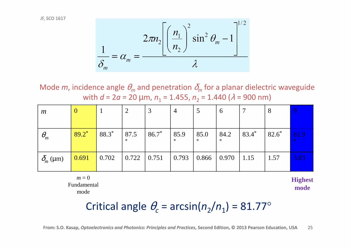
m 0 1 2 3 4 5 6 7 8 9
θm89.2° 88.3° 87.5
°
86.7° 85.9°
85.0°
84.2°
83.4° 82.6° 81.9°
δm (µm) 0.691 0.702 0.722 0.751 0.793 0.866 0.970 1.15 1.57 3.83
Critical angle θc = arcsin(n2/n1) = 81.77°
Highestmode
m = 0Fundamental
mode
Mode m, incidence angle θm and penetration δm for a planar dielectric waveguide
with d = 2a = 20 µm, n1 = 1.455, n2 = 1.440 (λ = 900 nm)
From: S.O. Kasap, Optoelectronics and Photonics: Principles and Practices, Second Edition, © 2013 Pearson Education, USA 26
JF, SCO 1617
From: S.O. Kasap, Optoelectronics and Photonics: Principles and Practices, Second Edition, © 2013 Pearson Education, USA 26
JF, SCO 1617
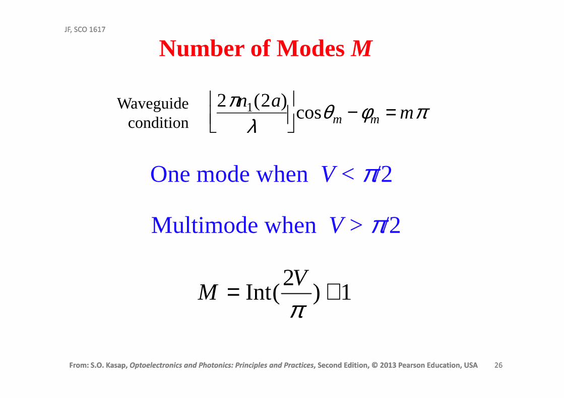
Number of Modes M
2πn1(2a)λ
cosθm −φm = mπWaveguide
condition
1)2
(Int +=πV
M
One mode when V < π/2
Multimode when V > π/2
From: S.O. Kasap, Optoelectronics and Photonics: Principles and Practices, Second Edition, © 2013 Pearson Education, USA 27
JF, SCO 1617
From: S.O. Kasap, Optoelectronics and Photonics: Principles and Practices, Second Edition, © 2013 Pearson Education, USA 27
JF, SCO 1617
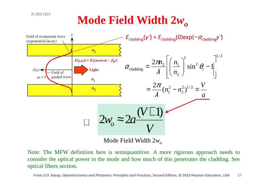
Mode Field Width 2wo
Ecladding(y′) = Ecladding(0)exp(−αcladdingy′)
a
Vnn
n
nni
=−≈
−
=
2/122
21
2/1
2
2
2
12cladding
)(2
1sin2
λπ
θλπα
∴V
Vawo
)1(22
+≈Mode Field Width 2wo
Note: The MFWdefinition here is semiquantitive. A more rigorous approach needs toconsider the optical power in the mode and how much of this penetrates the cladding. Seeoptical fibers section.
From: S.O. Kasap, Optoelectronics and Photonics: Principles and Practices, Second Edition, © 2013 Pearson Education, USA 28
JF, SCO 1617
From: S.O. Kasap, Optoelectronics and Photonics: Principles and Practices, Second Edition, © 2013 Pearson Education, USA 28
JF, SCO 1617
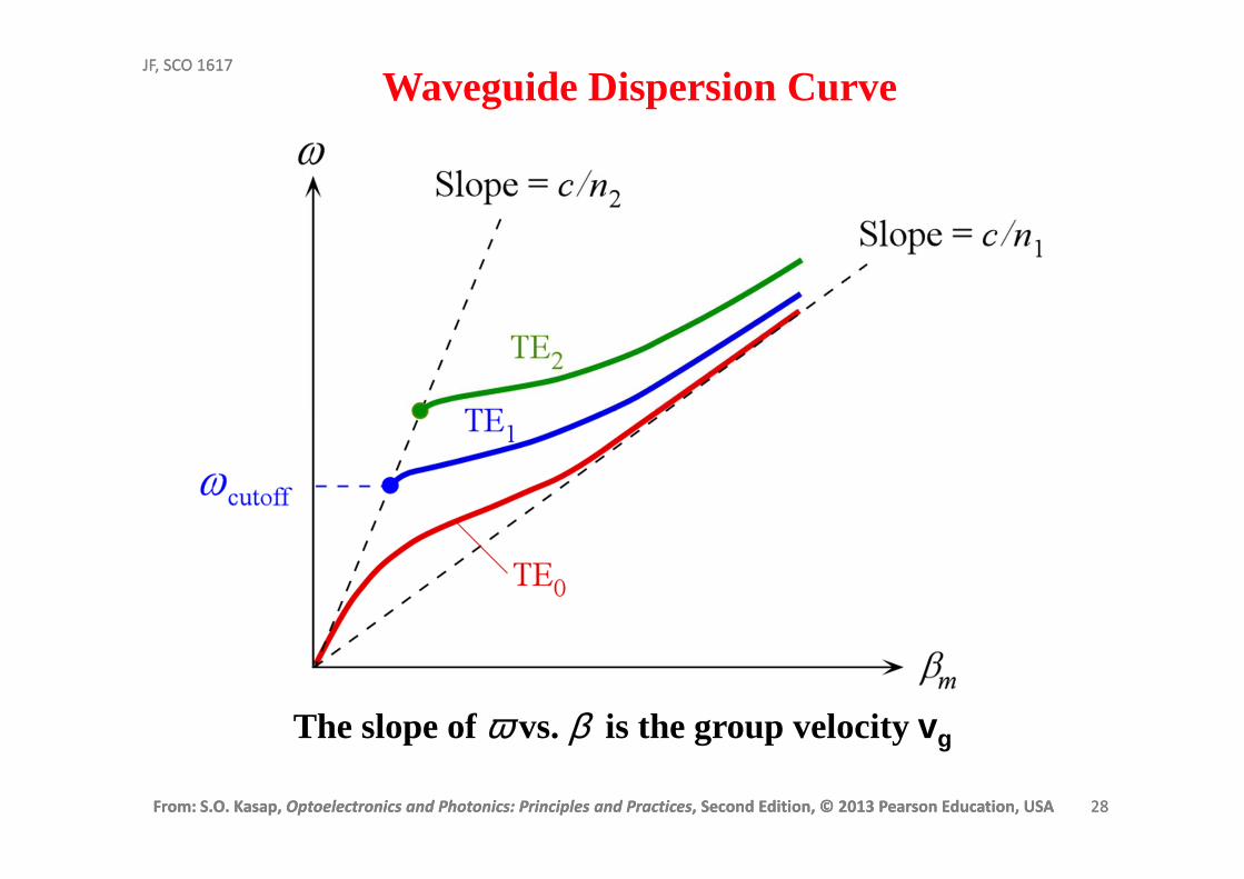
The slope of ω vs. β is the group velocity vg
Waveguide Dispersion Curve
From: S.O. Kasap, Optoelectronics and Photonics: Principles and Practices, Second Edition, © 2013 Pearson Education, USA 29
JF, SCO 1617
From: S.O. Kasap, Optoelectronics and Photonics: Principles and Practices, Second Edition, © 2013 Pearson Education, USA 29
JF, SCO 1617
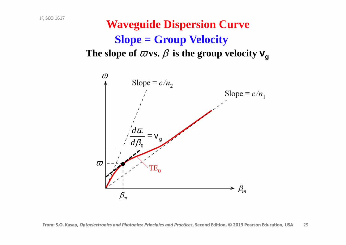
The slope of ω vs. β is the group velocity vg
Waveguide Dispersion Curve
gv=0β
ωd
d
Slope = Group Velocity
βm
ω
From: S.O. Kasap, Optoelectronics and Photonics: Principles and Practices, Second Edition, © 2013 Pearson Education, USA 30
JF, SCO 1617
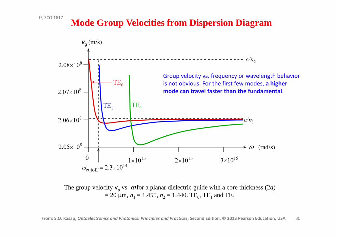
Mode Group Velocities from Dispersion Diagram
The group velocity vg vs. ω for a planar dielectric guide with a core thickness (2a) = 20 µm, n1 = 1.455, n2 = 1.440. TE0, TE1 and TE4
Group velocity vs. frequency or wavelength behavior
is not obvious. For the first few modes, a higher
mode can travel faster than the fundamental.
From: S.O. Kasap, Optoelectronics and Photonics: Principles and Practices, Second Edition, © 2013 Pearson Education, USA 31
JF, SCO 1617
ω
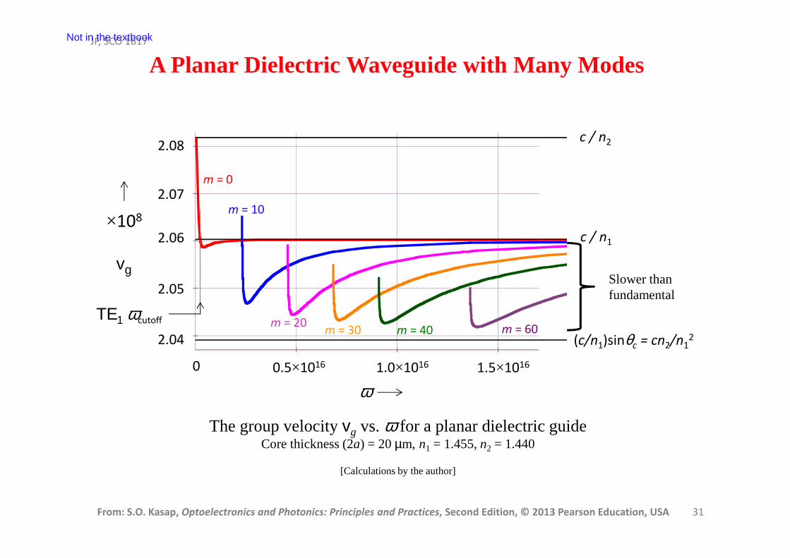
A Planar Dielectric Waveguide with Many Modes
The group velocity vg vs. ω for a planar dielectric guideCore thickness (2a) = 20 µm, n1 = 1.455, n2 = 1.440
[Calculations by the author]
ω
vg
0.5×10¹⁶ 1.0×10¹⁶ 1.5×10160
2.04
2.05
2.06
2.07
2.08
×108
c / n2
c / n1
(c/n1)sinθc = cn2/n12
m = 0
m = 10
m = 20m = 30 m = 40 m = 60
ΤΕ1 ωcutoff
Slower than fundamental
Not in the textbook
From: S.O. Kasap, Optoelectronics and Photonics: Principles and Practices, Second Edition, © 2013 Pearson Education, USA 32
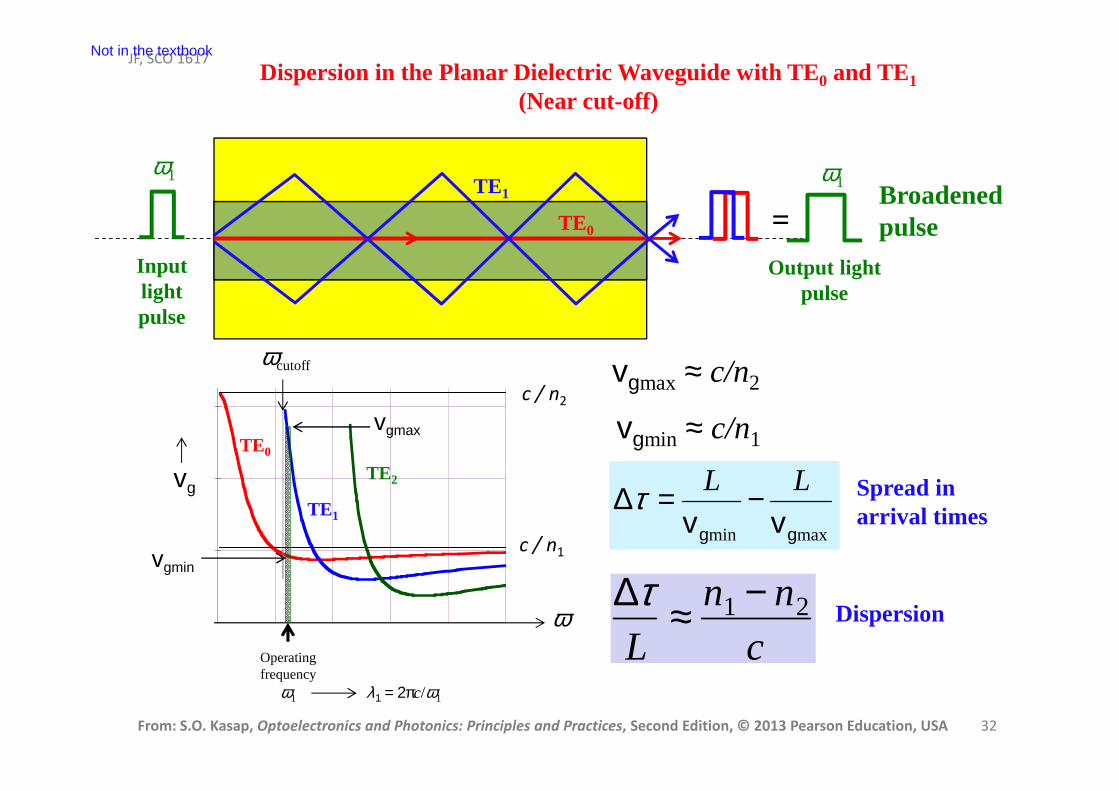
JF, SCO 1617Dispersion in the Planar Dielectric Waveguide with TE0 and TE1
(Near cut-off)
TE0
TE1
=Broadened pulse
Output light pulse
Inputlightpulse
ω
vg
ωcutoff
c / n2
c / n1
Operatingfrequency
ω1
vgmax
vgmin
vgmax ≈ c/n2
vgmin ≈ c/n1
maxmin gg vvLL −=∆τ
∆τL
≈ n1 − n2
c
Spread in arrival times
Dispersion
TE1
TE0
TE2
ω1 ω1
λ1 = 2πc/ω1
Not in the textbook
From: S.O. Kasap, Optoelectronics and Photonics: Principles and Practices, Second Edition, © 2013 Pearson Education, USA 33
JF, SCO 1617
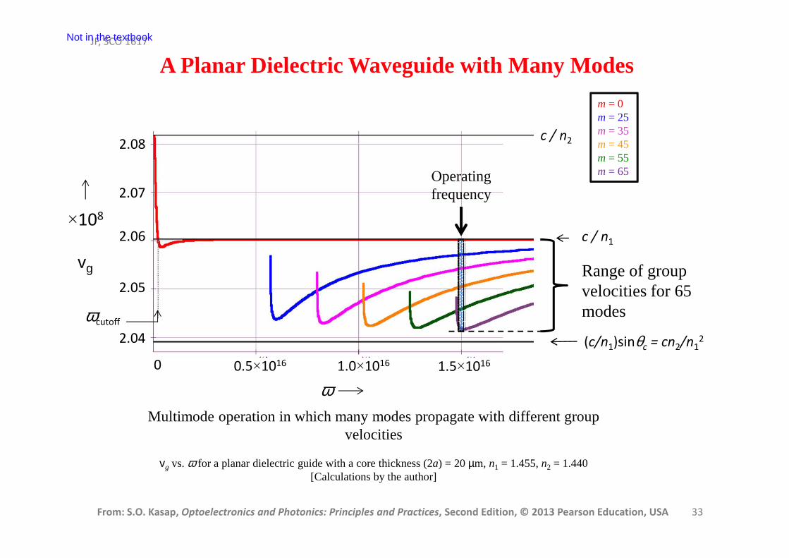
A Planar Dielectric Waveguide with Many Modes
Multimode operation in which many modes propagate with different group velocities
vg vs. ω for a planar dielectric guide with a core thickness (2a) = 20 µm, n1 = 1.455, n2 = 1.440[Calculations by the author]
ω
vg
0.5×10¹⁶ 1.0×10¹⁶ 1.5×10160
2.04
2.05
2.06
2.07
2.08
×108
c / n2
c / n1
(c/n1)sinθc = cn2/n12
m = 0m = 25m = 35m = 45m = 55m = 65
ωcutoff
Operatingfrequency
Range of groupvelocities for 65 modes
Not in the textbook
From: S.O. Kasap, Optoelectronics and Photonics: Principles and Practices, Second Edition, © 2013 Pearson Education, USA 34
JF, SCO 1617
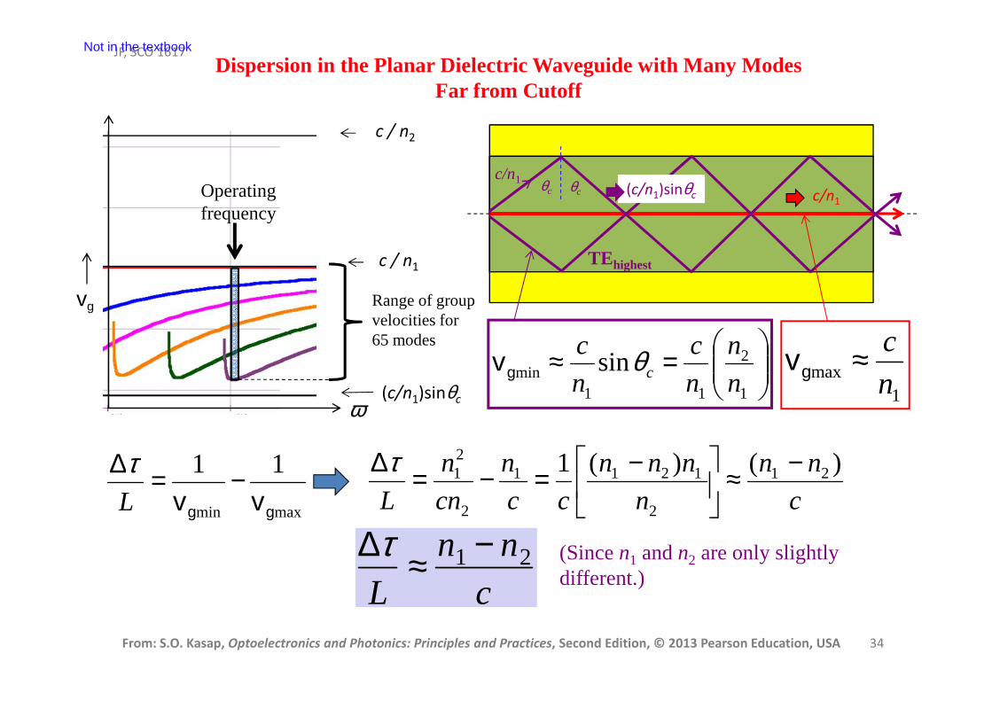
Dispersion in the Planar Dielectric Waveguide with Many ModesFar from Cutoff
TEhighest
θc θc
c/n1(c/n1)sinθc c/n1
=≈
1
2
11min sin
n
n
n
c
n
ccθgv
1max n
c≈gv
maxmin
11
gg vv−=∆
L
τc
nn
n
nnn
cc
n
cn
n
L
)()(1 21
2
1211
2
21 −≈
−=−=∆τ
∆τL
≈ n1 − n2
c(Since n1 and n2 are only slightly different.)
ω
vg
c / n1
(c/n1)sinθc
Operatingfrequency
Range of groupvelocities for 65 modes
c / n2
Not in the textbook
From: S.O. Kasap, Optoelectronics and Photonics: Principles and Practices, Second Edition, © 2013 Pearson Education, USA 35
JF, SCO 1617
TEhighest
θc
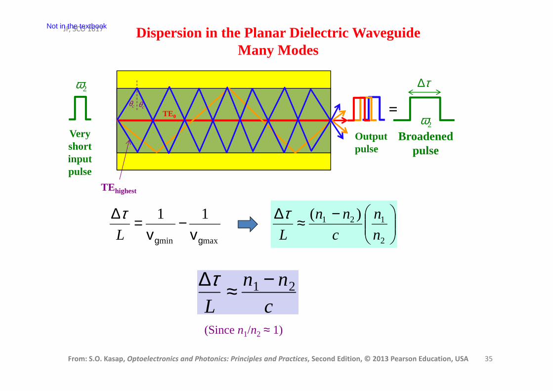
Dispersion in the Planar Dielectric WaveguideMany Modes
=
Broadened pulse
Outputpulse
Very short inputpulse
ω2
ω2
θc
TE0
maxmin
11
gg vv−=∆
L
τ
−≈∆
2
121 )(
n
n
c
nn
L
τ
∆τL
≈ n1 − n2
c
∆τ
Not in the textbook
(Since n1/n2 ≈ 1)
From: S.O. Kasap, Optoelectronics and Photonics: Principles and Practices, Second Edition, © 2013 Pearson Education, USA 36
JF, SCO 1617
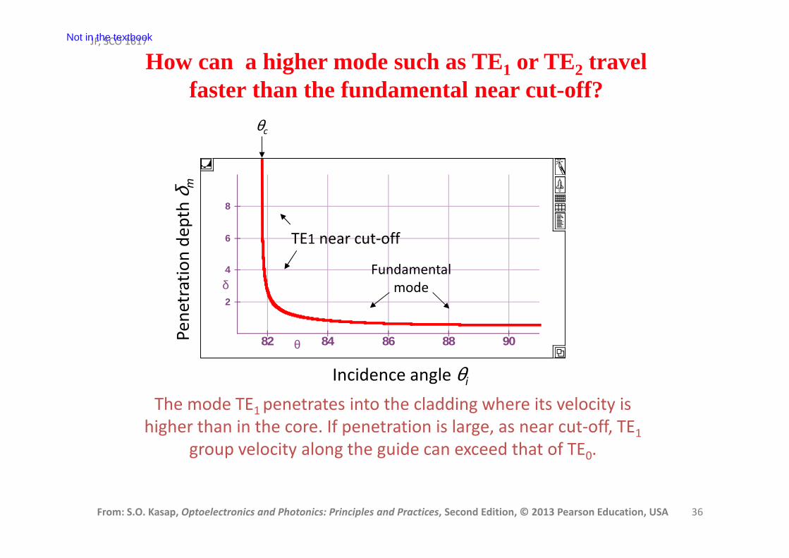
How can a higher mode such as TE1 or TE2 travel faster than the fundamental near cut-off?
Not in the textbook
The mode TE1 penetrates into the cladding where its velocity is
higher than in the core. If penetration is large, as near cut-off, TE1
group velocity along the guide can exceed that of TE0.
2
4
6
8
δ
82 84 86 88 90θ
θc
Pe
ne
tra
tio
n d
ep
th δ
m
Incidence angle θi
TE1 near cut-off
Fundamental
mode
From: S.O. Kasap, Optoelectronics and Photonics: Principles and Practices, Second Edition, © 2013 Pearson Education, USA 37
JF, SCO 1617
From: S.O. Kasap, Optoelectronics and Photonics: Principles and Practices, Second Edition, © 2013 Pearson Education, USA 37
JF, SCO 1617
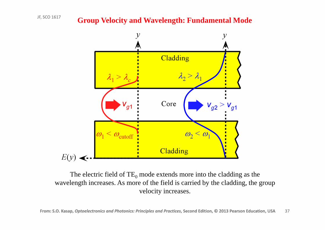
The electric field of TE0 mode extends more into the cladding as the wavelength increases. As more of the field is carried by the cladding, the group
velocity increases.
Group Velocity and Wavelength: Fundamental Mode
From: S.O. Kasap, Optoelectronics and Photonics: Principles and Practices, Second Edition, © 2013 Pearson Education, USA 38
JF, SCO 1617
From: S.O. Kasap, Optoelectronics and Photonics: Principles and Practices, Second Edition, © 2013 Pearson Education, USA 38
JF, SCO 1617
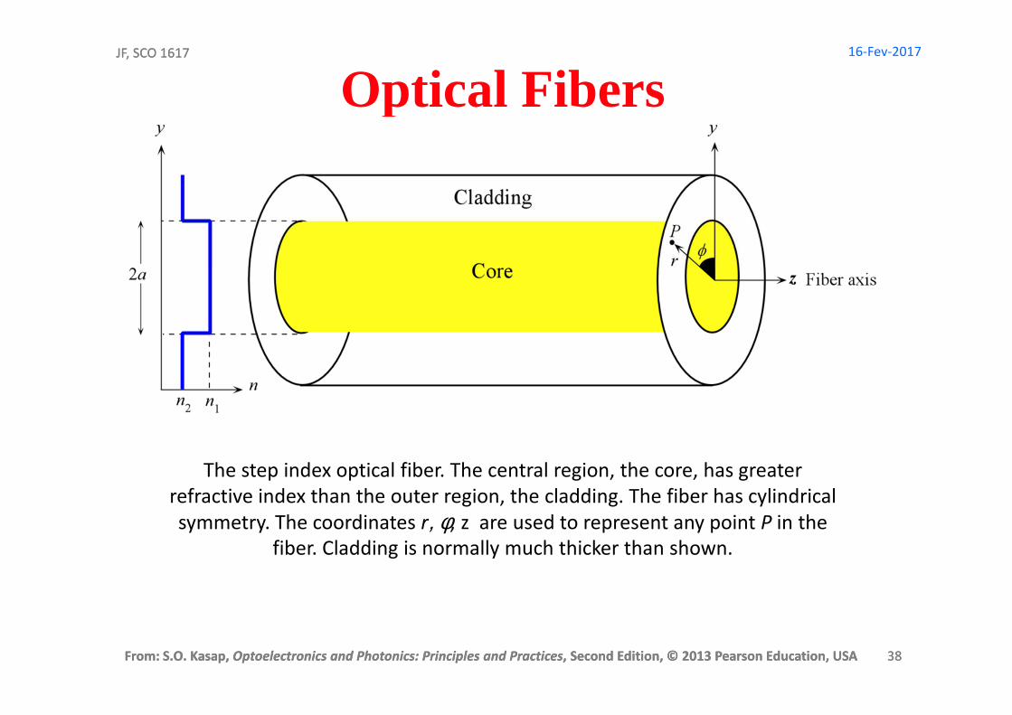
Optical Fibers
The step index optical fiber. The central region, the core, has greater
refractive index than the outer region, the cladding. The fiber has cylindrical
symmetry. The coordinates r, φ, z are used to represent any point P in the
fiber. Cladding is normally much thicker than shown.
16-Fev-2017


![[S. O. Kasap] Principles of Electronic Materials a(BookZZ.org)](https://img.pdfslide.us/doc/110x75/563dbb44550346aa9aabb659/s-o-kasap-principles-of-electronic-materials-abookzzorg.jpg)