Embed Size (px)
DESCRIPTION
manual dialux evo
Citation preview
PDF generated using the open source mwlib toolkit. See http://code.pediapress.com/ for more information.PDF generated at: Fri, 18 Dec 2015 23:31:45 CET
DIALux evo manualA collection of all wiki articles
Contents 1
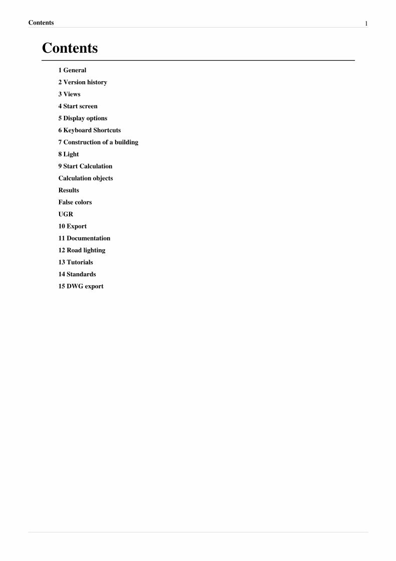
Contents1 General
2 Version history
3 Views
4 Start screen
5 Display options
6 Keyboard Shortcuts
7 Construction of a building
8 Light
9 Start Calculation
Calculation objects
Results
False colors
UGR
10 Export
11 Documentation
12 Road lighting
13 Tutorials
14 Standards
15 DWG export
1 General 2
1 General
General informationWelcome to DIALux evo This wiki is intended to help you to work quickly and effectively with DIALux evo. If youhave already had experience with Windows programmes, you should not have difficulty getting started. To enableyou to acquire the knowledge to work professionally with DIALux DIAL offers regular training courses andseminars. You can find out about the dates and contents of these seminars at www.dial.de [1] [1]. Innovations andupdates can also be found on our homepage
System requirementsSystem requirements•• CPU with SSE2 support•• 4 GB RAM (min. 2GB)•• OpenGL 3.3 graphics card(1 GB RAM)(for evo 4.0)•• OpenGL 3.0 graphics card(1 GB RAM)(for evo 4.1)•• Resolution min. 1024px x 768px•• Windows Vista SP2 (32bit/64bit)•• Windows 7 (32-bit/6-bit)•• Windows 8 (32-bit/64-bit)
InstallationStart the 32-bit or 64-bit setup.exe file and follow the instructions in the installation programme. To improve thesoftware certain information is sent to DIAL during setup: - a unique ID whereby no direct inference to your personis permitted - information regarding the operating system installed (version, service pack...) - hardware information (RAM, display resolution, ...) - detailed information about the capabilities of your graphics adapterNo personal data are transmitted. Further information is available here:Terms and conditions of useData security
Is parallel installation of DIALux evo and DIALux 4 possible?
Parallel installation of DIALux 4 and DIALux evo on your computer is easy and causes no problems. Neither of theprogrammes has any influence on the other. The electronic catalogues of luminaire and lamp manufacturers aresupported by both programmes. If both programmes are being run at the same time, the luminaires and lamps fromthe catalogues are transferred to both programmes.
32-bit or 64-bit version? Which version should I use?
If you have suitable hardware and a 64-bit operating system, then you have access to a larger RAM. It is possible tocreate and calculate larger projects in DIALux evo. Old DIALux projects (DIALux 2.0 to DIALux 4.11) can nolonger be opened with this version. Our recommendation is the 64-bit version The 32-bit version should only be usedif•• a 32-bit operating system is installed on your computer•• if you wish to continue to import old DIALux projectsDIALux evo projects can be loaded very easily by both versions as long as the RAM has the required capacityavailable.
1 General 3
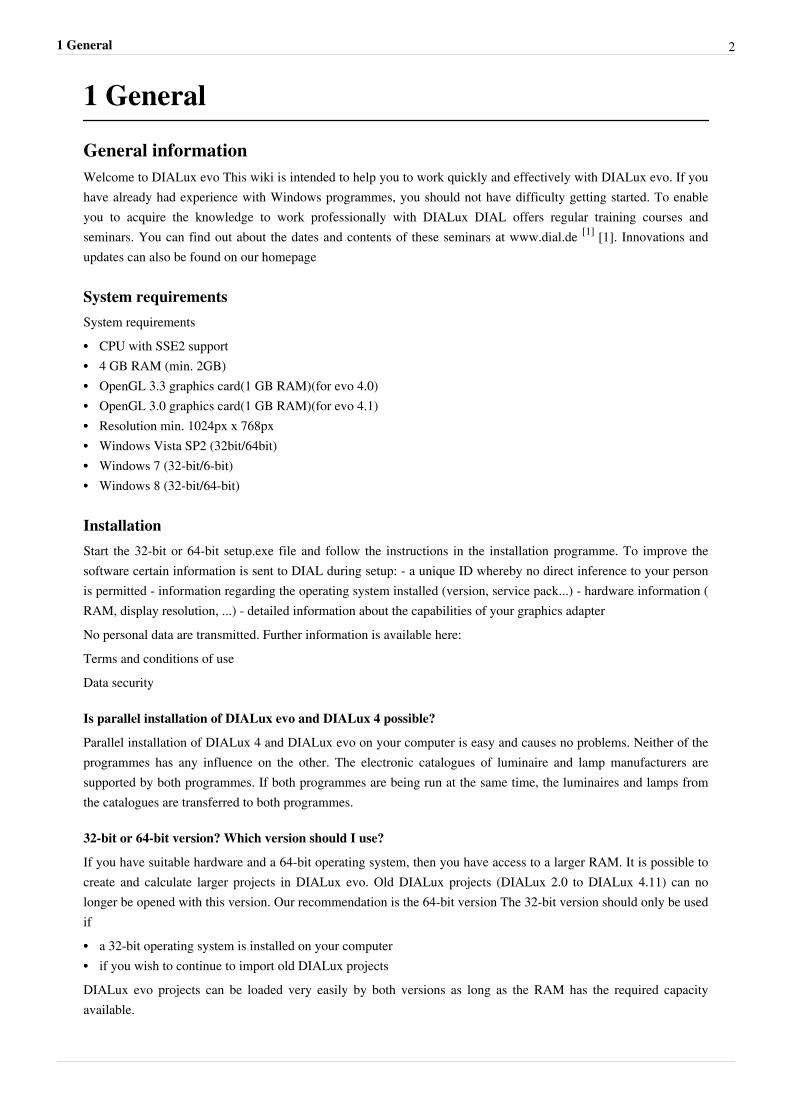
DIALux 4
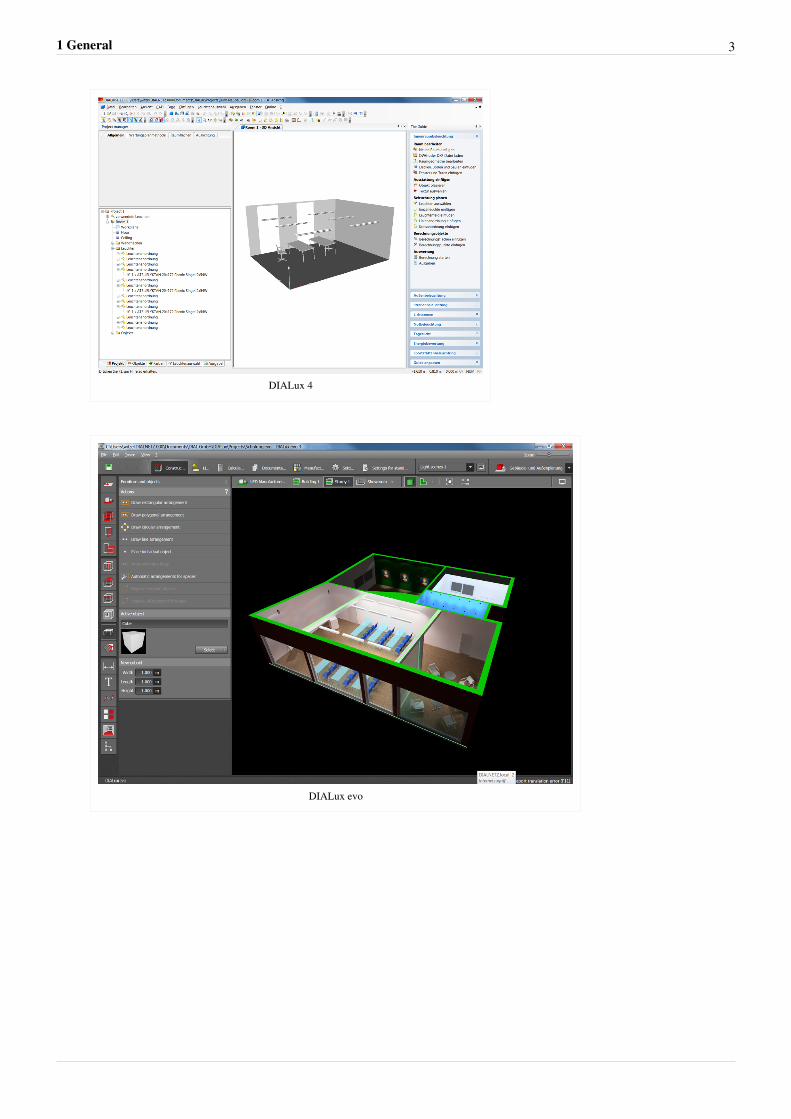
DIALux evo
1 General 4
Operating principleDIALux evo is divided up into a simple mode and tool concept. In each mode you will find typical tools for workingwith each.
Can several instances of DIALux evo be started at the same time?
It is possible to have several instances of DIALux evo open at the same time and thus work on different projects.
N.B: There may be problems when exchanging data
between the different instances.
General settingsVia the menu [File -> Settings -> General settings] open the mode "SettingsGeneral informationHere you can define how often DIALux evo should remind you to store your project and the maximum number ofworking steps that can be cancelled.Language settingsAfter installation DIALux evo operates in the language of your operating system. Under "Language settings" youcan change the language of the interface and the output and also switch from metric to imperial dimensions. Here itis also possible to set the display of the photometric units displayed in the European system or the imperial system.CADHere you can specify how many decimal places to be displayed on dimension lines.Project settingsHere you enter the project folder in which your projects are normally storedOther saving locationsFurniture and materials can also be stored on your hard disc. Here you can set the respective storage location. Onlyin extreme cases is it necessary to change the storage location.Output settingsIf desired a footer text of your own and a personal logo in the header can be displayed in the printed output. Adjustthe settings here as required.
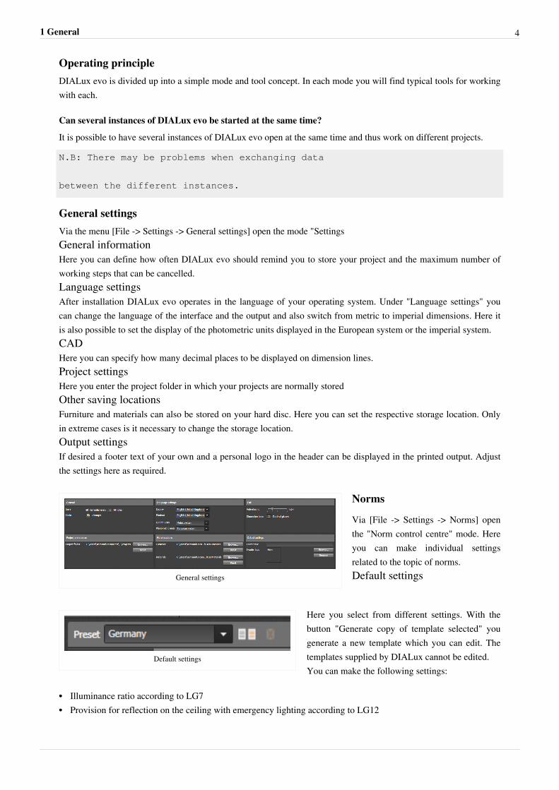
General settings
Norms
Via [File -> Settings -> Norms] openthe "Norm control centre" mode. Hereyou can make individual settingsrelated to the topic of norms.Default settings
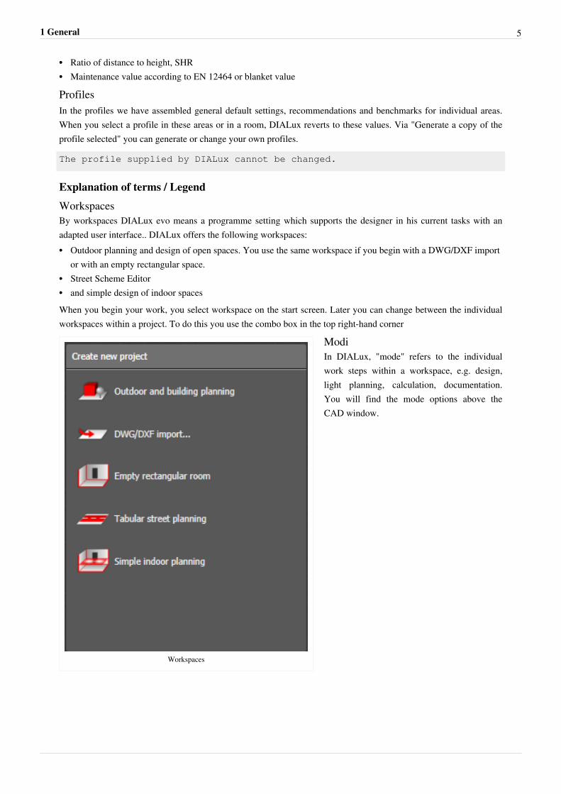
Default settings
Here you select from different settings. With thebutton "Generate copy of template selected" yougenerate a new template which you can edit. Thetemplates supplied by DIALux cannot be edited.You can make the following settings:
•• Illuminance ratio according to LG7•• Provision for reflection on the ceiling with emergency lighting according to LG12
1 General 5
•• Ratio of distance to height, SHR•• Maintenance value according to EN 12464 or blanket value
ProfilesIn the profiles we have assembled general default settings, recommendations and benchmarks for individual areas.When you select a profile in these areas or in a room, DIALux reverts to these values. Via "Generate a copy of theprofile selected" you can generate or change your own profiles.
The profile supplied by DIALux cannot be changed.
Explanation of terms / Legend
WorkspacesBy workspaces DIALux evo means a programme setting which supports the designer in his current tasks with anadapted user interface.. DIALux offers the following workspaces:•• Outdoor planning and design of open spaces. You use the same workspace if you begin with a DWG/DXF import
or with an empty rectangular space.•• Street Scheme Editor•• and simple design of indoor spacesWhen you begin your work, you select workspace on the start screen. Later you can change between the individualworkspaces within a project. To do this you use the combo box in the top right-hand corner
Workspaces
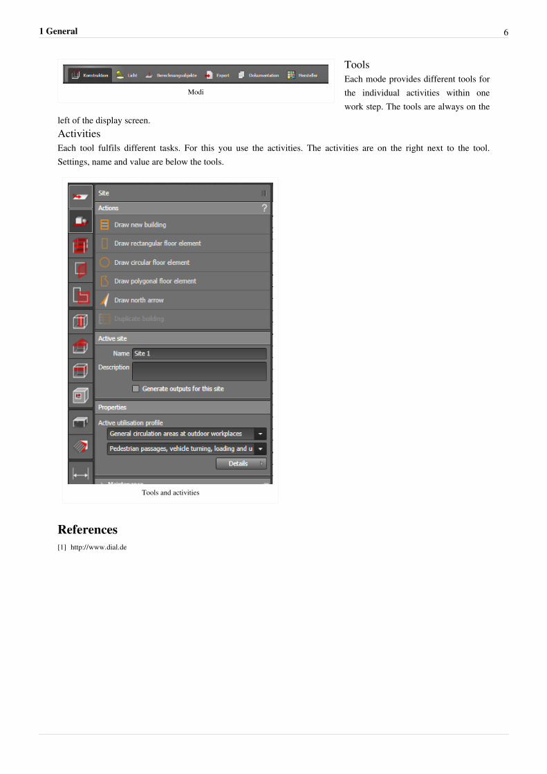
ModiIn DIALux, "mode" refers to the individualwork steps within a workspace, e.g. design,light planning, calculation, documentation.You will find the mode options above theCAD window.
1 General 6
Modi
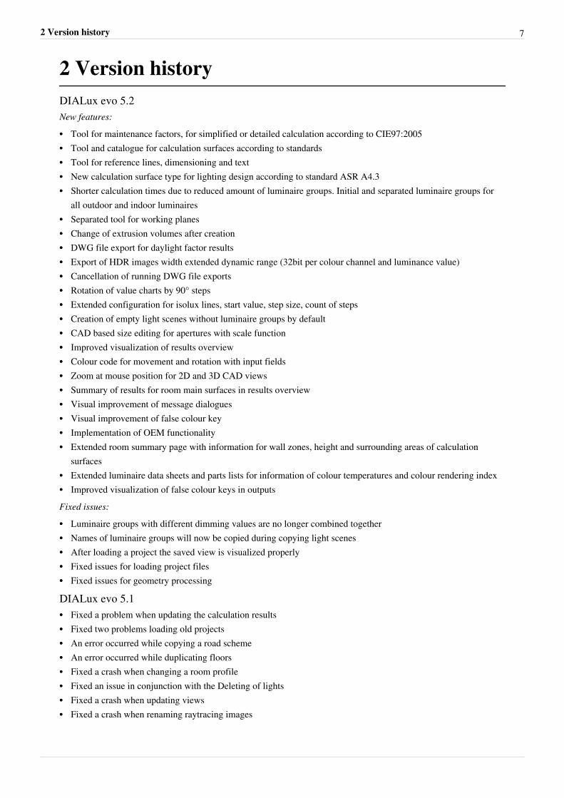
ToolsEach mode provides different tools forthe individual activities within onework step. The tools are always on the
left of the display screen.ActivitiesEach tool fulfils different tasks. For this you use the activities. The activities are on the right next to the tool.Settings, name and value are below the tools.
Tools and activities
References[1] http:/ / www. dial. de
2 Version history 7
2 Version historyDIALux evo 5.2New features:
•• Tool for maintenance factors, for simplified or detailed calculation according to CIE97:2005•• Tool and catalogue for calculation surfaces according to standards•• Tool for reference lines, dimensioning and text•• New calculation surface type for lighting design according to standard ASR A4.3•• Shorter calculation times due to reduced amount of luminaire groups. Initial and separated luminaire groups for
all outdoor and indoor luminaires•• Separated tool for working planes•• Change of extrusion volumes after creation•• DWG file export for daylight factor results•• Export of HDR images width extended dynamic range (32bit per colour channel and luminance value)•• Cancellation of running DWG file exports•• Rotation of value charts by 90° steps•• Extended configuration for isolux lines, start value, step size, count of steps•• Creation of empty light scenes without luminaire groups by default•• CAD based size editing for apertures with scale function•• Improved visualization of results overview•• Colour code for movement and rotation with input fields•• Zoom at mouse position for 2D and 3D CAD views•• Summary of results for room main surfaces in results overview•• Visual improvement of message dialogues•• Visual improvement of false colour key•• Implementation of OEM functionality•• Extended room summary page with information for wall zones, height and surrounding areas of calculation
surfaces•• Extended luminaire data sheets and parts lists for information of colour temperatures and colour rendering index•• Improved visualization of false colour keys in outputsFixed issues:
•• Luminaire groups with different dimming values are no longer combined together•• Names of luminaire groups will now be copied during copying light scenes•• After loading a project the saved view is visualized properly•• Fixed issues for loading project files•• Fixed issues for geometry processing
DIALux evo 5.1•• Fixed a problem when updating the calculation results•• Fixed two problems loading old projects•• An error occurred while copying a road scheme•• An error occurred while duplicating floors•• Fixed a crash when changing a room profile•• Fixed an issue in conjunction with the Deleting of lights•• Fixed a crash when updating views•• Fixed a crash when renaming raytracing images
2 Version history 8
•• An issue with invalid material properties•• Two errors in the Undo-Redo function•• Fixed a bug that resulted in a fatal loading Error when loading projects•• Fixed a crash related to the placing of materials•• An error during the start of DIALux evo•• An error in the display of UGR and GR results•• Fixed a crash during calculation•• An error occurred while adding additional lanes in the street planning•• An error in the building Opening Tool•• Fixed a crash when determining the page numbers in the documentation•• The DWG Export now displays correct imperial units•• Fixed a problem when saving projects•• Fixed a crash when doing multiple selection of room main surfaces•• Fixed a bug when creating empty, rectangular rooms•• A problem with the use of several adaptive calculation areas•• Fixed an issue with invalid Time Zones•• Incorrect calculation of the floor area of rooms•• Fixed a bug when importing DIALux 4 projects•• A problem associated with defective luminaire data•• A problem with the accessibility of the website of DIAL from DIALux evo•• Some improvements in the translation of DIALux evo•• An improvement in the HDR export function•• An error message in the street planning•• Fixed an issue with the correct display of grid points
DIALux evo 5•• Display and configuration of value grids in the CAD•• Color Selection for value grids•• Highlighting of minima and maxima•• Combination of false colors, isolines and value grids on surfaces.•• Display of these combinations in the renderings for the outputs.•• Coupling beetwen false colors and isolines canceled.•• Isolines can now be set and colred separately for each area.•• The view tool was added to the export mode.•• Displaying article number to product names of luminaires, in the active luminaire, the data sheet window, in the
tooltips of tiles, as well as in the list view.•• Graphical review of the results tool.Connection of the progress bar with the result toolWith the elimination of the calculation mode detail information that inform about the calculation progress are missedwhen calculating.This information will be available in the result tool from this version.
2 Version history 9
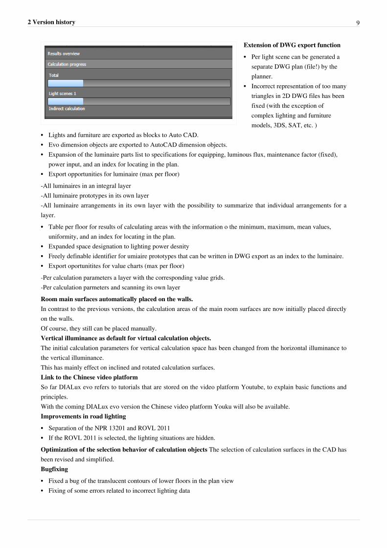
Extension of DWG export function
•• Per light scene can be generated aseparate DWG plan (file!) by theplanner.
•• Incorrect representation of too manytriangles in 2D DWG files has beenfixed (with the exception ofcomplex lighting and furnituremodels, 3DS, SAT, etc. )
•• Lights and furniture are exported as blocks to Auto CAD.•• Evo dimension objects are exported to AutoCAD dimension objects.•• Expansion of the luminaire parts list to specifications for equipping, luminous flux, maintenance factor (fixed),
power input, and an index for locating in the plan.•• Export opportunities for luminaire (max per floor)-All luminaires in an integral layer-All luminaire prototypes in its own layer-All luminaire arrangements in its own layer with the possibility to summarize that individual arrangements for alayer.•• Table per floor for results of calculating areas with the information o the minimum, maximum, mean values,
uniformity, and an index for locating in the plan.•• Expanded space designation to lighting power desnity•• Freely definable identifier for umiaire prototypes that can be written in DWG export as an index to the luminaire.•• Export oportunitites for value charts (max per floor)-Per calculation parameters a layer with the corresponding value grids.-Per calculation parmeters and scanning its own layerRoom main surfaces automatically placed on the walls.In contrast to the previous versions, the calculation areas of the main room surfaces are now initially placed directlyon the walls.Of course, they still can be placed manually.Vertical illuminance as default for virtual calculation objects.The initial calculation parameters for vertical calculation space has been changed from the horizontal illuminance tothe vertical illuminance.This has mainly effect on inclined and rotated calculation surfaces.Link to the Chinese video platformSo far DIALux evo refers to tutorials that are stored on the video platform Youtube, to explain basic functions andprinciples.With the coming DIALux evo version the Chinese video platform Youku will also be available.Improvements in road lighting
•• Separation of the NPR 13201 and ROVL 2011•• If the ROVL 2011 is selected, the lighting situations are hidden.Optimization of the selection behavior of calculation objects The selection of calculation surfaces in the CAD hasbeen revised and simplified.Bugfixing
•• Fixed a bug of the translucent contours of lower floors in the plan view•• Fixing of some errors related to incorrect lighting data
2 Version history 10
•• Fixed a bug related to missing material data•• Resolving a display error in the UGR diagram•• Fixed some bugs related to the geometry creation.•• Fixed some errors related to the creation of windows.•• Fixed some errors in generating and changing of calculation surfaces.•• Fixed a bug when changing maintenance factors.•• Fixed a bug when moving windows.•• Fixed a bug when changing room main surfaces•• Resolve some problems with the undo/redo function•• Optimizing the display of long texts in the user interface.•• Resolve some problems in generating the output tree when loading older projects.•• Fixed a bug when changing dimension objects.•• Fixed some bugs in the user interface when changing the tool and mode.•• Improve the image quality of the raytracer, reducing the moire effect.•• Optimization of the output tree in relating to speed and selection of displayed pages.•• Optimization of discarding of calculation results in geometry changes.•• Fixed a bug when using your own logos in the outputs.•• When generating the output pages no more blank pages now be generated.•• Fixed a bug with the help reference grid. The help reference grid no longer returns to the default value 1m.•• Fixed a bug when working with templates in the editions.•• Optimization of the manipulators in the side view and the multiple use of materials.•• Fixed a bug after deleting floor contours.•• Fixed a bug when using descriptive text in the outputs.•• Fixed some errors when working with floor elements.•• Optimization of the manipulator for cutouts.•• Optimization of graphic card tests during setup.•• Fixed a bug when creating cutout objects.•• Optimized the manipulators for large DWG files.•• Optimized the view objects for the outputs.•• Optimized the zoom function.•• Fixed a bug that resulted in very dark scenes.•• Deleting projects templates is possible again.•• Fixed a bug related to materials on windows.•• Fixed a bug which prevented to mark the templates as favorites.•• Immediate display of new templates in the selection.•• Fixed a bug that prevented copying of storeys.•• Fixed a bug which hides out contours after loading.•• Optimized the functions for generating and moving roof panels.•• Fixed a bug when displaying page settings in the outputs.•• Optimized the DWG export.•• Fixed a bug which resulted in a false position of calculation objects.•• Optimization of memory usage when loading projects with huge 3DS objects.•• Display the correct preview when loading LDT and IES files.•• Fixed a bug when deleting cutout objects.•• Resolving a display error of projects with daylight calculation.•• Fixed a bug when insert combined objects.•• Resolving a representation error after importing DIALux 4 projects (32bit)
2 Version history 11
•• When drawing areas of activity the function can now be completed by using the context menu.•• Resolving a rounding error in the road calculation.•• Fixed a bug when changing tools in the context of road planning.•• Fixed a bug when combining sphere objects.•• Fixed a bug in the object preview.• Fixed a bug in the function “Replace material”• Fixed a bug when loading projects per drag &drop directly from the Windows Explorer•• Fixed a bug when saving converted projects.•• Optimization of the selection of buildings.•• Fixed a bug when starting DIALux evo.•• Optimization of the selection behavior in the street tool.•• Optimization of the mouse in certain dialogues.•• Fixed a bug when loading broken materials.•• Fixed a bug related to the selected outputs.•• Fixed a bug in the alignment of luminaires.•• Fixed a bug when changingtime zones for daylight calculation.•• Optimized the display of luminaire models for the calculation.•• Fixed a bug when displaying textures in the raytracing image.•• Fixed a bug that could lead to lack of calculation results on the working plane.
DIALux evo 4.1•• An error in the result tool was fixed that can be caused by an outdated .NetFramework.Adjustment of the setup to the .NetVersion 4.5.2•• An error when creating a raytrace image for repeated call of the raytracer was fixed.•• A problem when creating the geometry while loading a project was fixed.•• A Problem when loading projects with incorrect geometry was fixed.•• Avoid double bottom plates in generating empty floors.•• An error when loading evo 3.1 projects with custom output templates was fixed.•• An error when loading a not correct converted evo 3.1 project was fixed.•• An error when using material textures in calculated projects was fixed.•• An error in the identification of the calculation status of an older, calculated project was fixed.•• An error when interpreting the minimum required DIALux evo version number of a saved project was fixed.•• An error in the result tool in conjunction with the Undo function was fixed.•• Some translation errors were fixed.•• An error in the output of the floorplan view in conjunction with extremely large DWG files was fixed.•• An error in the generation of automatic contours with very small angle of the contour was fixed.•• An error in the generation of inclined floor elements was fixed.•• An error in the generation of rectangular hole contours without valid coordinate system, or with an area of 0m2
was fixed.•• An error in the calculation of invalid calculation areas was fixed.•• An error when displaying the room floor plan in the results summary was fixed.•• An error in the conversion of regularity for US standards in the outputs was fixed.•• Change of evo 4.1 graphics card requirements of OpenGL3.3 back to OpenGL3.0.•• A problem displaying Imperial units in the result tool was fixed.•• An error in generating skylights in the floorplan was fixed.•• A Problem in generating polygonal calculation areas outdoors was fixed.•• An error when placing visual task areas on objects was fixed.
2 Version history 12
•• An error in the outputs after loading old projects was fixed.•• A display error on Intel HD graphics cards was fixed.•• An error when loading projects with daylight calculation was fixed.•• An error when copying floors with reference lines was fixed.•• An error when drawing building openings on the roof in the front view was fixed.•• An error in display of values in the false color display in imperial units was fixed.•• Correction of the lighting power density for the US market.
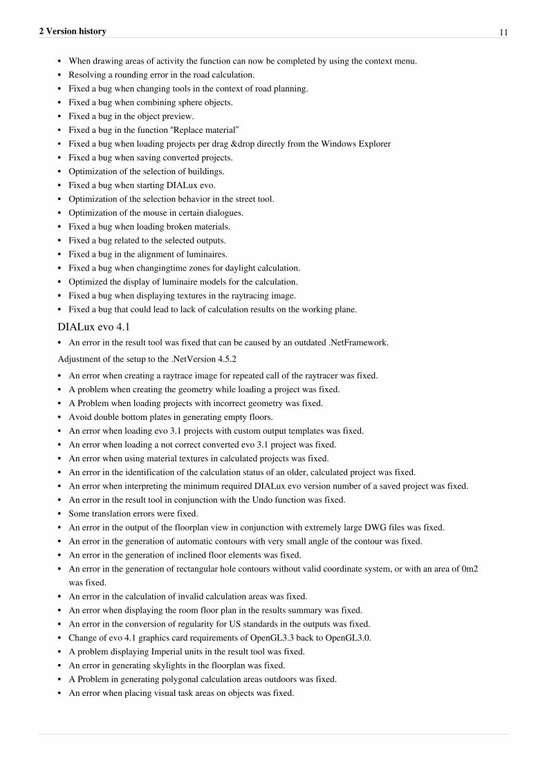
DIALux evo 4.0Restructuring GUI•• In the user interface , some changes were made. The calculation can be started now via the two buttons above the
CAD. This makes it possible to start the calculation at any time , regardless of what mode you are in. The tool forlighting scene generation is now in the "light" mode. The export mode is now available at all times . The tool forcreating raytracing files is now in the mode export. All tools for generating calculation objects can be found in thenew mode calculation objects.
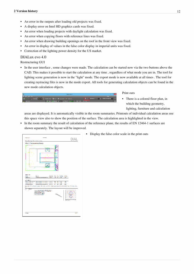
Print outs•• There is a colored floor plan, in
which the building geometry,lighting, furniture and calculation
areas are displayed. It is automatically visible in the room summaries. Printouts of individual calculation areas usethis space view also to show the position of the surface. The calculation area is highlighted in the view.
•• In the room summary the result of calculation of the reference plane, the results of EN 12464-1 surfaces areshown separately. The layout will be improved.
•• Display the false color scale in the print outs
2 Version history 13
•• The modeling is always visible for areas of activity in the resulttable.
•• In the fixture part list the luminous flux of light sources, theefficiencies and the luminous flux of fixtures for relative andabsolute measured photometric data are shown optional. It usesthe data of the luminaires used in the project, so fixtures withdifferent configurations are listed multiple times.
•• For fixtures with different equipment separate data sheets aregenerated.
•• The tables of calculation results in the print out gets a newlayout, so that similar information can be better summarized.The new layout is easier to read and fits better with the rest ofthe page layout.
•• Reference values from the space profile are displayed in theprint out in brackets next to the calculated values.
•• The results of the main room surfaces are no longer shown separately in the room summary.•• The output "Description" is only available in the output tree, if the user entered such a description.•• Some information will appear multiple times in the output templates. For example, the calculation results of the
working plane appears both in the summary and in the surface output. These redundant outputs are removed fromthe templates. However, the user of DIALux evo they can still select them and adjust its output individually.
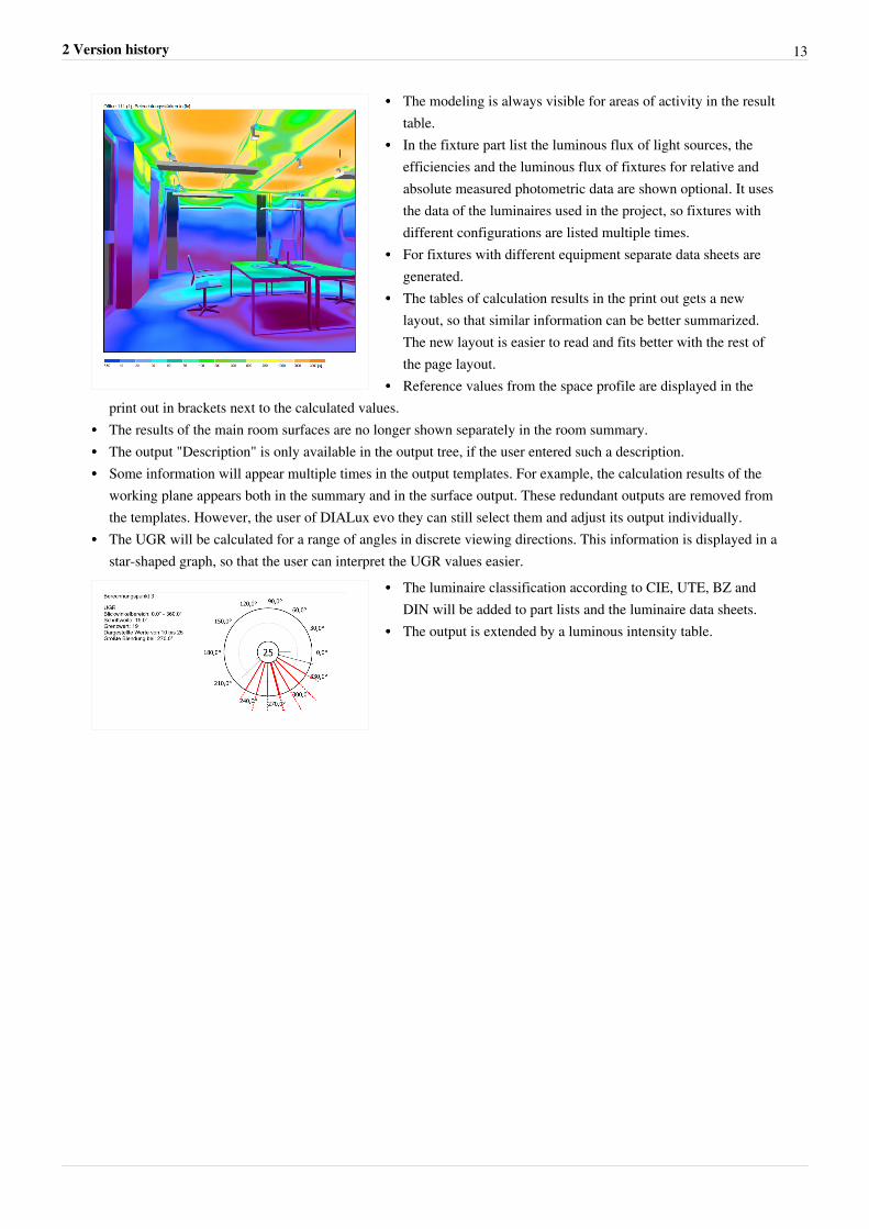
•• The UGR will be calculated for a range of angles in discrete viewing directions. This information is displayed in astar-shaped graph, so that the user can interpret the UGR values easier.
•• The luminaire classification according to CIE, UTE, BZ andDIN will be added to part lists and the luminaire data sheets.
•• The output is extended by a luminous intensity table.
2 Version history 14
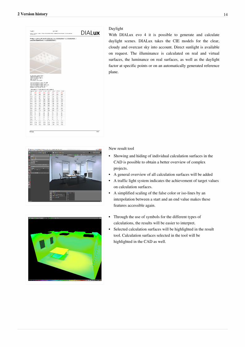
DaylightWith DIALux evo 4 it is possible to generate and calculatedaylight scenes. DIALux takes the CIE models for the clear,cloudy and overcast sky into account. Direct sunlight is availableon request. The illuminance is calculated on real and virtualsurfaces, the luminance on real surfaces, as well as the daylightfactor at specific points or on an automatically generated referenceplane.
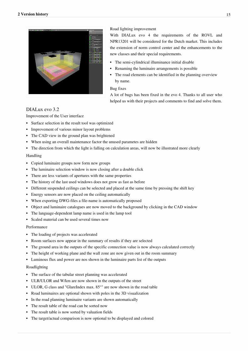
New result tool•• Showing and hiding of individual calculation surfaces in the
CAD is possible to obtain a better overview of complexprojects.
•• A general overview of all calculation surfaces will be added•• A traffic light system indicates the achievement of target values
on calculation surfaces.•• A simplified scaling of the false color or iso-lines by an
interpolation between a start and an end value makes thesefeatures accessible again.
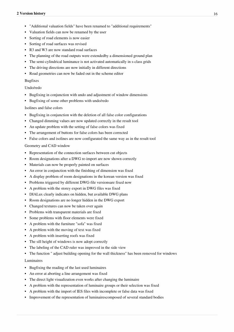
•• Through the use of symbols for the different types ofcalculations, the results will be easier to interpret.
•• Selected calculation surfaces will be highlighted in the resulttool. Calculation surfaces selected in the tool will behighlighted in the CAD as well.
2 Version history 15
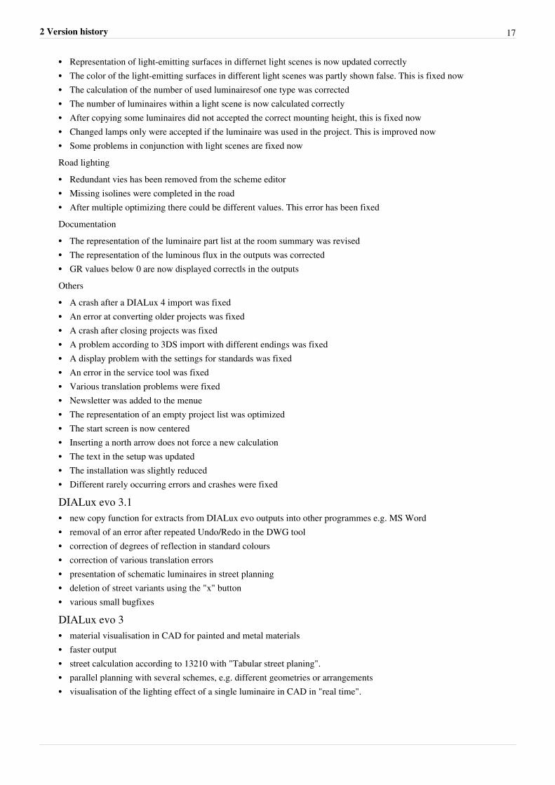
Road lighting improvementWith DIALux evo 4 the requirements of the ROVL andNPR13201 will be considered for the Dutch market. This includesthe extension of norm control center and the enhancements to thenew classes and their special requirements.
•• The semi-cylindrical illuminance initial disable•• Renaming the luminaire arrangements is possible•• The road elements can be identified in the planning overview
by name.Bug fixesA lot of bugs has been fixed in the evo 4. Thanks to all user whohelped us with their projects and comments to find and solve them.
DIALux evo 3.2Improvement of the User interface•• Surface selection in the result tool was optimized•• Improvement of various minor layout problems•• The CAD view in the ground plan was brightened•• When using an overall maintenance factor the unused parametes are hidden•• The direction from which the light is falling on calculation areas, will now be illustrated more clearlyHandling•• Copied luminaire groups now form new groups•• The luminaire selection window is now closing after a double click•• There are less variants of apertures with the same properties•• The history of the last used windows does not grow as fast as before•• Different suspended ceilings can be selected and placed at the same time by pressing the shift key•• Energy sensors are now placed on the ceiling automatically•• When exporting DWG-files a file-name is automatically proposed•• Object and luminaire catalogues are now moved to the background by clicking in the CAD window•• The language-dependent lamp name is used in the lamp tool•• Scaled material can be used several times nowPerformance•• The loading of projects was accelerated•• Room surfaces now appear in the summary of results if they are selected•• The ground area in the outputs of the specific connection value is now always calculated correctly•• The height of working plane and the wall zone are now given out in the room summary•• Luminous flux and power are nos shown in the luminaire parts list of the outputsRoadlighting•• The surface of the tabular street planning was accelerated•• ULR/ULOR and W/km are now shown in the outputs of the street•• ULOR, G class and "GlareIndex max. 85°" are now shown in the road table•• Road luminaires are optional shown with poles in the 3D visualization•• In the road planning luminaire variants are shown automatically•• The result table of the road can be sorted now•• The result table is now sorted by valuation fields•• The target/actual comparison is now optional to be displayed and colored
2 Version history 16
•• "Additional valuation fields" have been renamed to "additional requirements"•• Valuation fields can now be renamed by the user•• Sorting of road elements is now easier•• Sorting of road surfaces was revised•• R3 and W3 are now standard road surfaces•• The planning of the road outputs were extendedby a dimensioned ground plan•• The semi-cylindrical luminance is not activated automatically in s-class grids•• The driving directions are now initially in different directions•• Road geometries can now be faded out in the scheme editorBugfixesUndo/redo•• Bugfixing in conjunction with undo and adjustment of window dimensions•• Bugfixing of some other problems with undo/redoIsolines and false colors•• Bugfixing in conjunction with the deletion of all false color configurations•• Changed dimming values are now updated correctly in the result tool•• An update problem with the setting of false colors was fixed•• The arrangement of buttons for false colors has been corrected•• False colors and isolines are now configurated the same way as in the result toolGeometry and CAD window•• Representation of the connection surfaces between cut objects•• Room designations after a DWG re-import are now shown correctly•• Materials can now be properly painted on surfaces•• An error in conjunction with the finishing of dimension was fixed•• A display problem of room designations in the korean version was fixed•• Problems triggered by different DWG-file versionsare fixed now•• A problem with the storey export in DWG files was fixed•• DIALux clearly indicates on hidden, but available DWG plans•• Room designations are no longer hidden in the DWG export•• Changed textures can now be taken over again•• Problems with transparent materials are fixed•• Some problems with floor elements were fixed•• A problem with the furniture "sofa" was fixed•• A problem with the moving of text was fixed•• A problem with inserting roofs was fixed•• The sill height of windows is now adopt correctly•• The labeling of the CAD ruler was improved in the side view•• The function " adjust building opening for the wall thickness" has been removed for windowsLuminaires•• Bugfixing the reading of the last used luminaires•• An error at aborting a line arrangement was fixed•• The direct light visualization even works after changing the luminaire•• A problem with the representation of luminaire groups or their selection was fixed•• A problem with the import of IES files with incomplete or false data was fixed•• Improvement of the representation of luminairescomposed of several standard bodies
2 Version history 17
•• Representation of light-emitting surfaces in differnet light scenes is now updated correctly•• The color of the light-emitting surfaces in different light scenes was partly shown false. This is fixed now•• The calculation of the number of used luminairesof one type was corrected•• The number of luminaires within a light scene is now calculated correctly•• After copying some luminaires did not accepted the correct mounting height, this is fixed now•• Changed lamps only were accepted if the luminaire was used in the project. This is improved now•• Some problems in conjunction with light scenes are fixed nowRoad lighting•• Redundant vies has been removed from the scheme editor•• Missing isolines were completed in the road•• After multiple optimizing there could be different values. This error has been fixedDocumentation•• The representation of the luminaire part list at the room summary was revised•• The representation of the luminous flux in the outputs was corrected•• GR values below 0 are now displayed correctls in the outputsOthers•• A crash after a DIALux 4 import was fixed•• An error at converting older projects was fixed•• A crash after closing projects was fixed•• A problem according to 3DS import with different endings was fixed•• A display problem with the settings for standards was fixed•• An error in the service tool was fixed•• Various translation problems were fixed•• Newsletter was added to the menue•• The representation of an empty project list was optimized•• The start screen is now centered•• Inserting a north arrow does not force a new calculation•• The text in the setup was updated•• The installation was slightly reduced•• Different rarely occurring errors and crashes were fixed
DIALux evo 3.1•• new copy function for extracts from DIALux evo outputs into other programmes e.g. MS Word•• removal of an error after repeated Undo/Redo in the DWG tool•• correction of degrees of reflection in standard colours•• correction of various translation errors•• presentation of schematic luminaires in street planning•• deletion of street variants using the "x" button•• various small bugfixes
DIALux evo 3•• material visualisation in CAD for painted and metal materials•• faster output•• street calculation according to 13210 with "Tabular street planing".•• parallel planning with several schemes, e.g. different geometries or arrangements•• visualisation of the lighting effect of a single luminaire in CAD in "real time".
2 Version history 18
• evo "easy“ - a very simplified GUI enabling planning of simple rectangular spaces similar to the function inDIALux Light
•• energy evaluation according to EN 15193 - It is now possible to make a 'live' energy evaluation while planning.There are options for displaying in kWh/a or Leni or showing the costs in any selected currency.
•• Complete 64-bit version - the 64-bit version is not compatible with Windows XP and cannot load older DIALuxprojects. However there is a much larger memory for saving larger projects. In the setup it is possible to select theinstallation of a 32-bit version.
•• HDR image export•• Numerous small bugfixes
DIALux evo 2•• Export a screenshot as a jpg. or bmp. file•• Global false colours on al surfaces in CAD•• WASD control in CAD•• DWG Export•• Big improvement in performance, stability and hard disc usage•• Shift a room and zoom without the scroll wheel(P + left mouse click = shift, Z+ left mouse click = zoom)•• New floors can be inserted between two old floors•• Set the focal length of the camera (ALT+ right mouse click)•• New colour catalogue•• One-page output•• Sequence of tools in the different modes improved
Bugfixes•• Wrong translation•• Unclear behaviour remedied for different types of planning in the field arrangement•• Underside of the roof has a degree of reflectance of 70%•• Windows in the ground plan are now always correctly oriented•• 3D help lines visible in 2D plan•• Several floor elements can be selected simultaneously•• Textures can be scaled numerically and rotated•• The output tree has a better structure and is easier to read•• Many further bugfixes
DIALux evo 1•• Planning of whole buildings including outdoor spaces. Merging of indoor and outdoor lighting design•• Exchange of light between rooms and between indoors and outdoors•• Simplified and innovative operating concept•• Very simple building design•• Subsequent tuning of lighting scenes enables exact adjustment of the dimming values after calculation•• Rooms know intuitively how many luminaires of which type they require•• Up-to-date, fast calculation process•• Output in any paper format•• Selection of all important specifications by the norm control centre•• Scaleable interface•• Automatic room recognition•• Detailed manufacturer information•• Visualisation of transparent materials in CAD•• Calculation under consideration of reflecting materials
2 Version history 19
•• Visualisation and valuation of calculation results in CAD•• Realistic building apertures such as windows and doors•• Dimensioning and labelling directly in CAD•• Via "drag and drop" it is possible to insert furniture, surfaces ( textures) and luminaires easily i into the room•• At a glance false colours provide quantitative analyses in complex geometries•• Realistic textures and furniture•• Integrated raytracing creates photorealistic impressions at lightning speed•• Calculation under consideration of transparent materials•• Planning with LED luminaires and other coloured light sources•• Planning with colour filters, coloured light sources and coloured materials•• Interactive 3D-visualisation allows you to walk around the room•• Integration of 3DS objects into lighting design•• Import and export of .dwg and .dxf files. Importing and later exporting with results after successful completion of
the lighting design. No additional software required.•• Intelligent components always position wall luminaires correctly on the wall and computers on the table.•• With one click luminaires are directed at the illumination point
3 Views 20
3 Views
Views
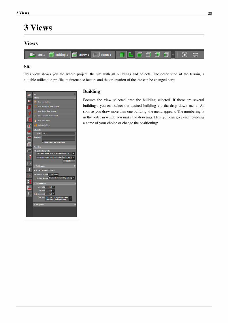
SiteThis view shows you the whole project, the site with all buildings and objects. The description of the terrain, asuitable utilization profile, maintenance factors and the orientation of the site can be changed here:
Building
Focuses the view selected onto the building selected. If there are severalbuildings, you can select the desired building via the drop down menu. Assoon as you draw more than one building, the menu appears. The numbering isin the order in which you make the drawings. Here you can give each buildinga name of your choice or change the positioning:
3 Views 21
Changing the name of the building
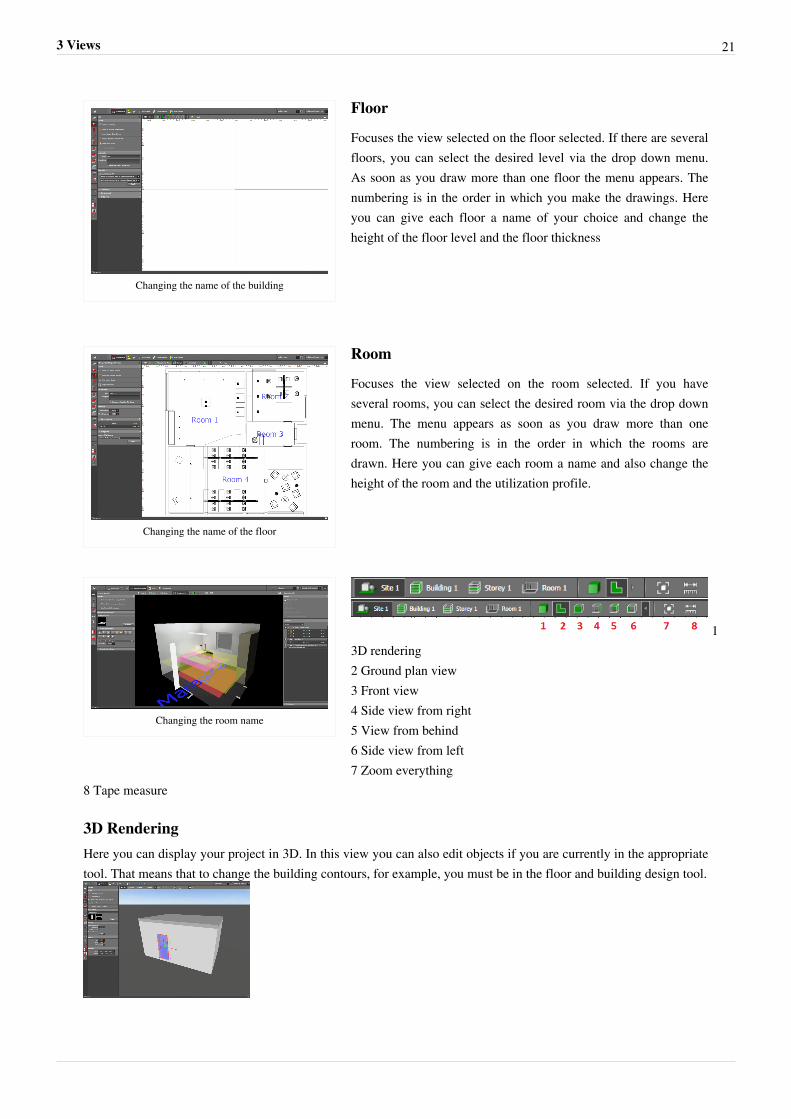
Floor
Focuses the view selected on the floor selected. If there are severalfloors, you can select the desired level via the drop down menu.As soon as you draw more than one floor the menu appears. Thenumbering is in the order in which you make the drawings. Hereyou can give each floor a name of your choice and change theheight of the floor level and the floor thickness
Changing the name of the floor
Room
Focuses the view selected on the room selected. If you haveseveral rooms, you can select the desired room via the drop downmenu. The menu appears as soon as you draw more than oneroom. The numbering is in the order in which the rooms aredrawn. Here you can give each room a name and also change theheight of the room and the utilization profile.
Changing the room name
13D rendering2 Ground plan view3 Front view4 Side view from right5 View from behind6 Side view from left7 Zoom everything
8 Tape measure
3D RenderingHere you can display your project in 3D. In this view you can also edit objects if you are currently in the appropriatetool. That means that to change the building contours, for example, you must be in the floor and building design tool.
3 Views 22
Ground plan viewThe ground plan view shows you a view of the selected object from above (e.g.floor 2).
Front view, Side view from right, View from behind, Side view from leftThese vies are usually hidden and can be switched on when needed.
Zoom everythingZooms in and out of the view selected so that all objects can be displayed in full screen mode.
Tape measureWith the aid of the tape measure you can measure and display a dimension in the drawing at any time.
4 Start screen 23
4 Start screen
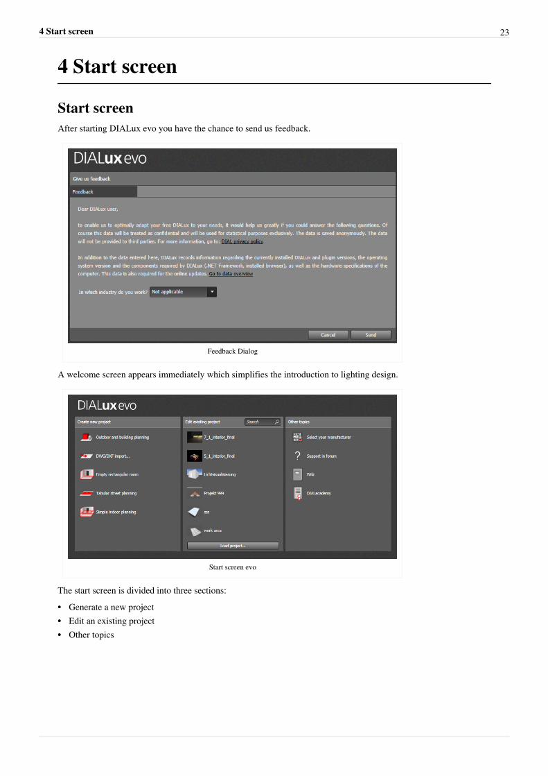
Start screenAfter starting DIALux evo you have the chance to send us feedback.
Feedback Dialog
A welcome screen appears immediately which simplifies the introduction to lighting design.
Start screen evo
The start screen is divided into three sections:•• Generate a new project•• Edit an existing project•• Other topics
4 Start screen 24
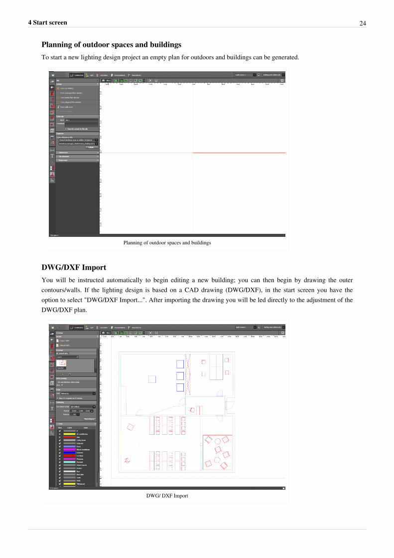
Planning of outdoor spaces and buildingsTo start a new lighting design project an empty plan for outdoors and buildings can be generated.
Planning of outdoor spaces and buildings
DWG/DXF ImportYou will be instructed automatically to begin editing a new building; you can then begin by drawing the outercontours/walls. If the lighting design is based on a CAD drawing (DWG/DXF), in the start screen you have theoption to select "DWG/DXF Import...". After importing the drawing you will be led directly to the adjustment of theDWG/DXF plan.
DWG/ DXF Import
4 Start screen 25
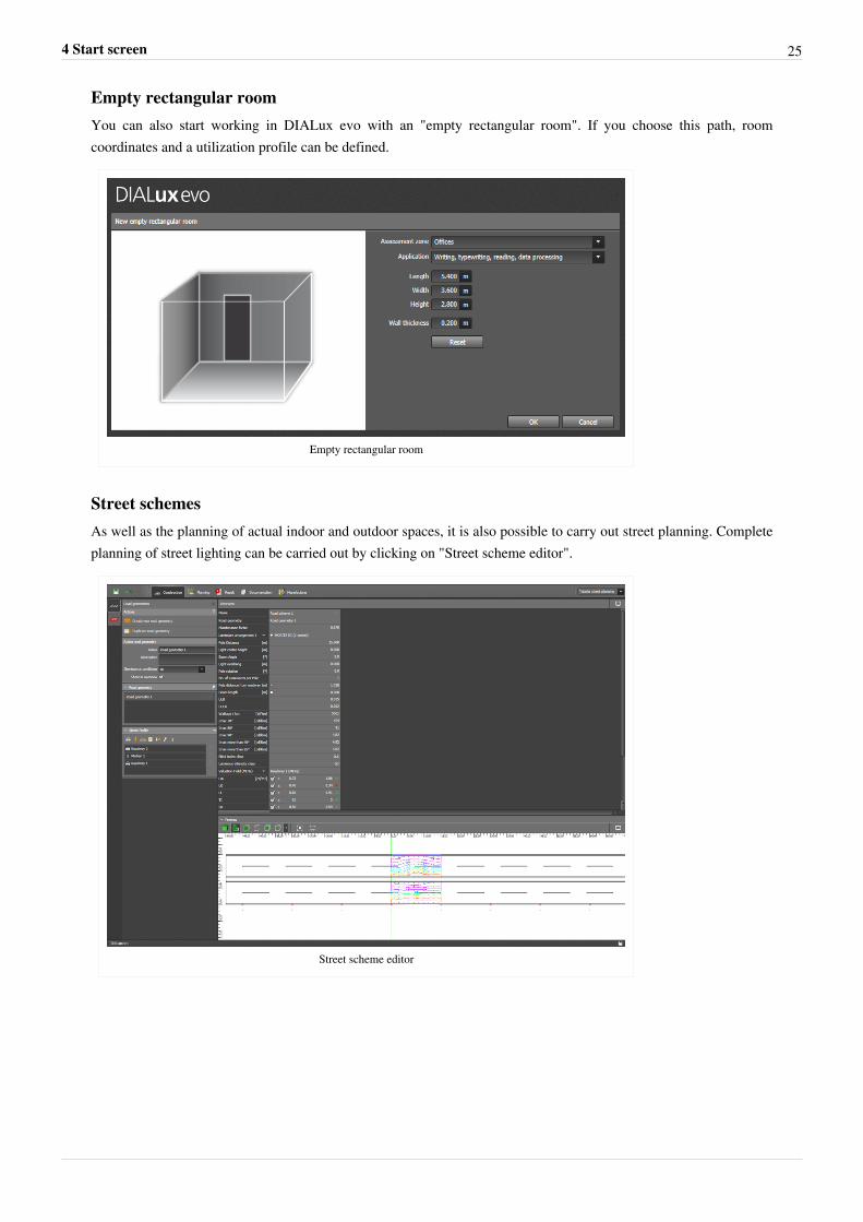
Empty rectangular roomYou can also start working in DIALux evo with an "empty rectangular room". If you choose this path, roomcoordinates and a utilization profile can be defined.
Empty rectangular room
Street schemesAs well as the planning of actual indoor and outdoor spaces, it is also possible to carry out street planning. Completeplanning of street lighting can be carried out by clicking on "Street scheme editor".
Street scheme editor
4 Start screen 26
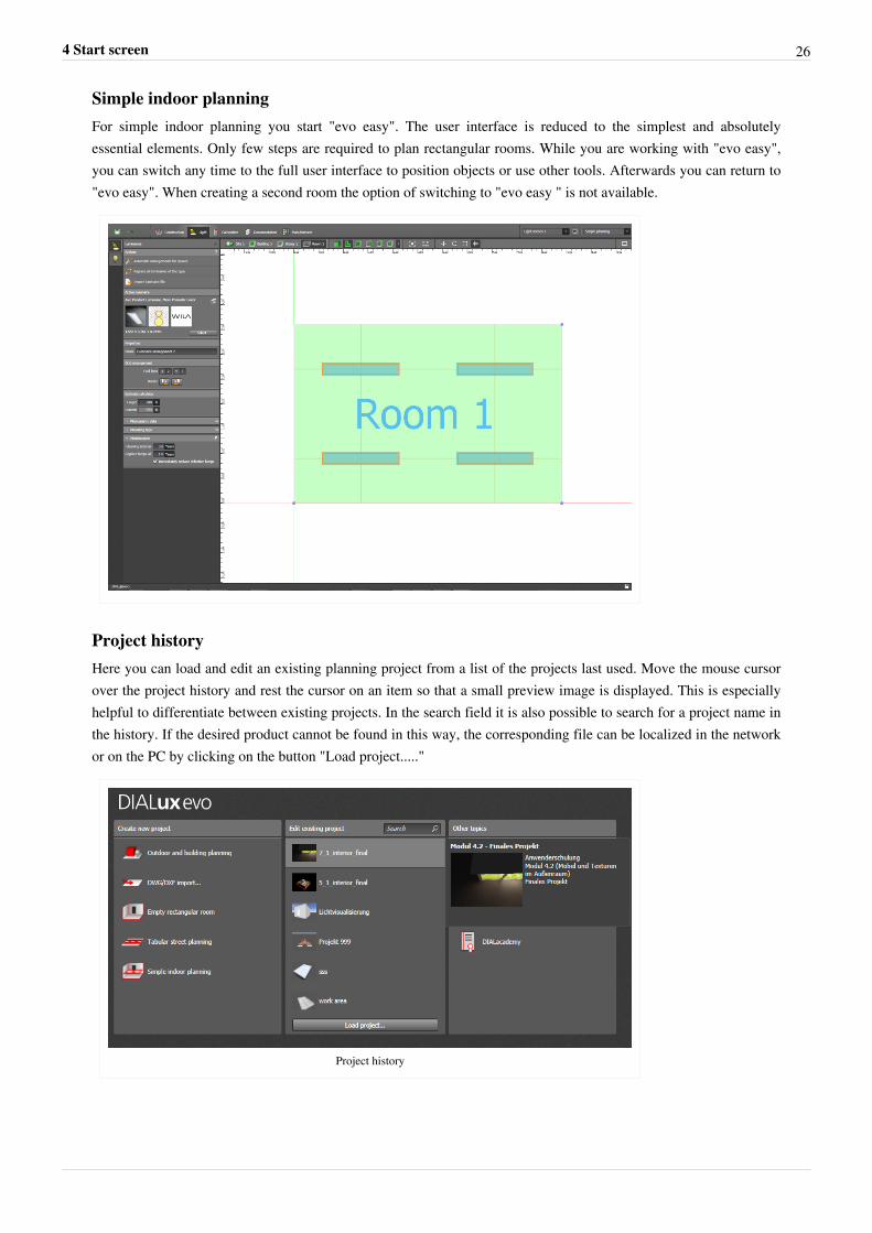
Simple indoor planningFor simple indoor planning you start "evo easy". The user interface is reduced to the simplest and absolutelyessential elements. Only few steps are required to plan rectangular rooms. While you are working with "evo easy",you can switch any time to the full user interface to position objects or use other tools. Afterwards you can return to"evo easy". When creating a second room the option of switching to "evo easy " is not available.
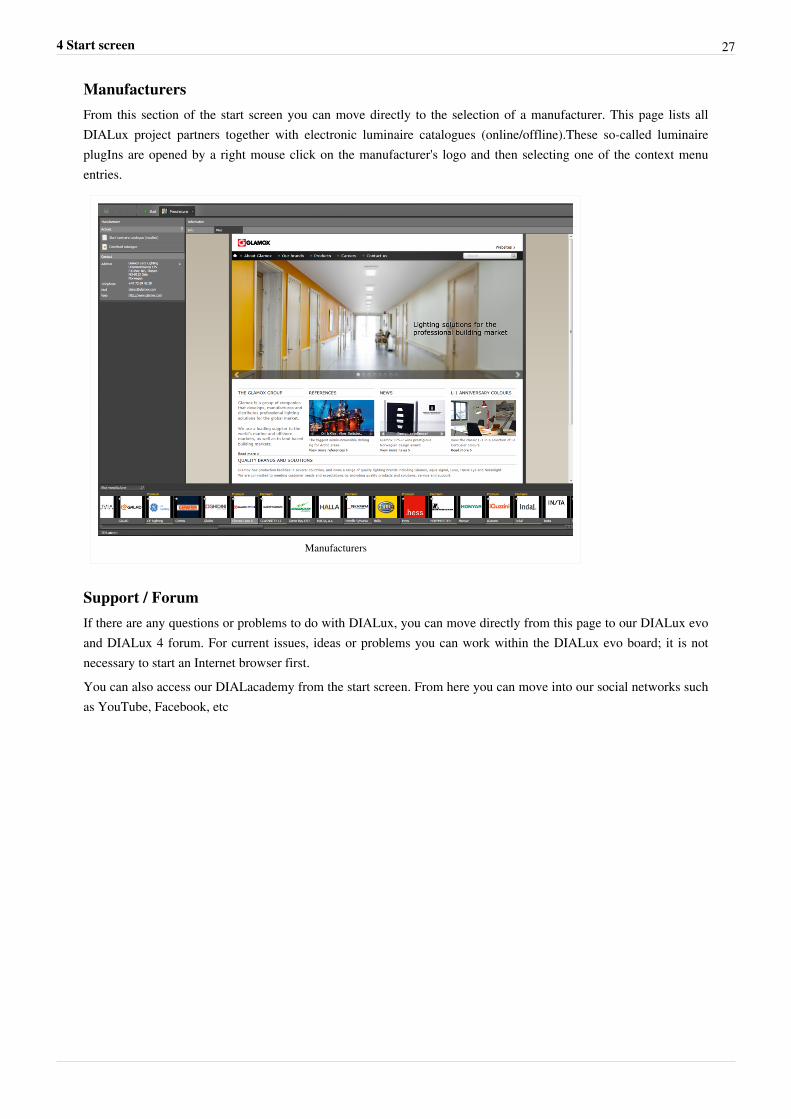
Project historyHere you can load and edit an existing planning project from a list of the projects last used. Move the mouse cursorover the project history and rest the cursor on an item so that a small preview image is displayed. This is especiallyhelpful to differentiate between existing projects. In the search field it is also possible to search for a project name inthe history. If the desired product cannot be found in this way, the corresponding file can be localized in the networkor on the PC by clicking on the button "Load project....."
Project history
4 Start screen 27
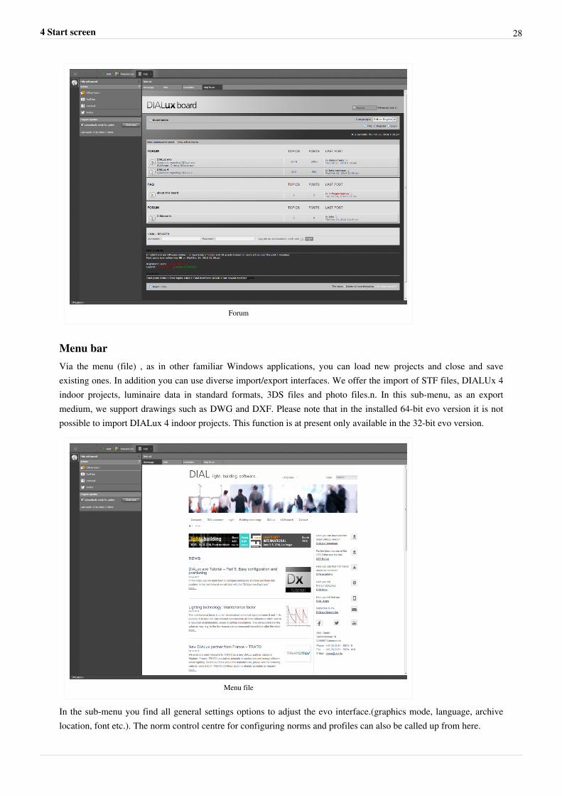
ManufacturersFrom this section of the start screen you can move directly to the selection of a manufacturer. This page lists allDIALux project partners together with electronic luminaire catalogues (online/offline).These so-called luminaireplugIns are opened by a right mouse click on the manufacturer's logo and then selecting one of the context menuentries.
Manufacturers
Support / ForumIf there are any questions or problems to do with DIALux, you can move directly from this page to our DIALux evoand DIALux 4 forum. For current issues, ideas or problems you can work within the DIALux evo board; it is notnecessary to start an Internet browser first.You can also access our DIALacademy from the start screen. From here you can move into our social networks suchas YouTube, Facebook, etc
4 Start screen 28
Forum
Menu barVia the menu (file) , as in other familiar Windows applications, you can load new projects and close and saveexisting ones. In addition you can use diverse import/export interfaces. We offer the import of STF files, DIALUx 4indoor projects, luminaire data in standard formats, 3DS files and photo files.n. In this sub-menu, as an exportmedium, we support drawings such as DWG and DXF. Please note that in the installed 64-bit evo version it is notpossible to import DIALux 4 indoor projects. This function is at present only available in the 32-bit evo version.
Menu file
In the sub-menu you find all general settings options to adjust the evo interface.(graphics mode, language, archivelocation, font etc.). The norm control centre for configuring norms and profiles can also be called up from here.
4 Start screen 29
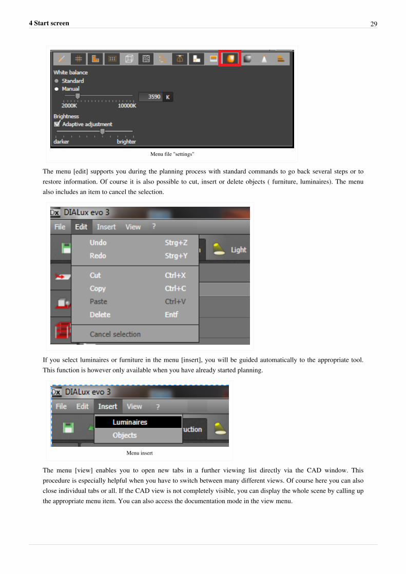
Menu file "settings"
The menu [edit] supports you during the planning process with standard commands to go back several steps or torestore information. Of course it is also possible to cut, insert or delete objects ( furniture, luminaires). The menualso includes an item to cancel the selection.
If you select luminaires or furniture in the menu [insert], you will be guided automatically to the appropriate tool.This function is however only available when you have already started planning.
Menu insert
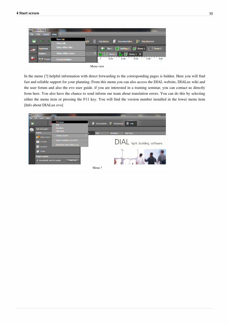
The menu [view] enables you to open new tabs in a further viewing list directly via the CAD window. Thisprocedure is especially helpful when you have to switch between many different views. Of course here you can alsoclose individual tabs or all. If the CAD view is not completely visible, you can display the whole scene by calling upthe appropriate menu item. You can also access the documentation mode in the view menu.
4 Start screen 30
Menu view
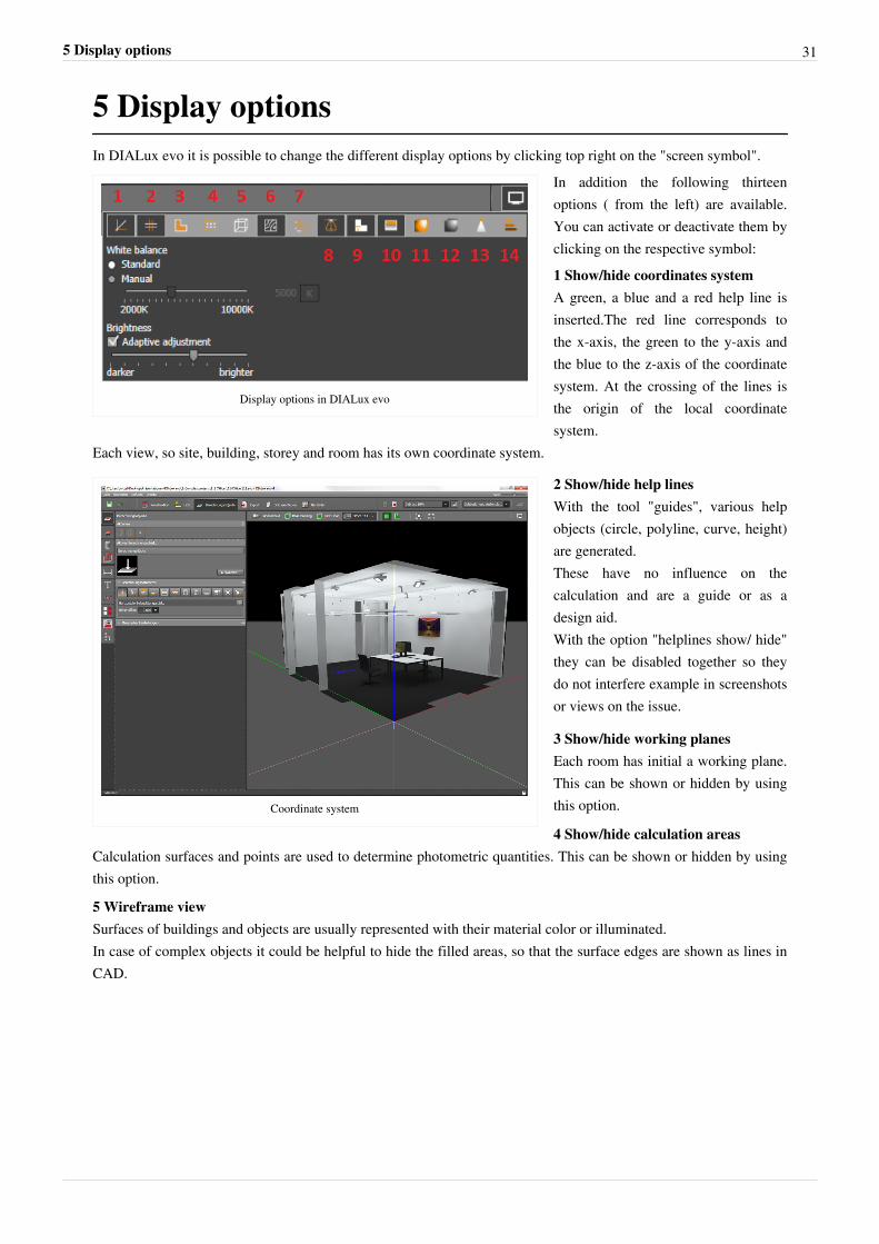
In the menu [?] helpful information with direct forwarding to the corresponding pages is hidden. Here you will findfast and reliable support for your planning. From this menu you can also access the DIAL website, DIALux wiki andthe user forum and also the evo user guide. if you are interested in a training seminar, you can contact us directlyfrom here. You also have the chance to send inform our team about translation errors. You can do this by selectingeither the menu item or pressing the F11 key. You will find the version number installed in the lower menu item[Info about DIALux evo]
Menu ?
5 Display options 31
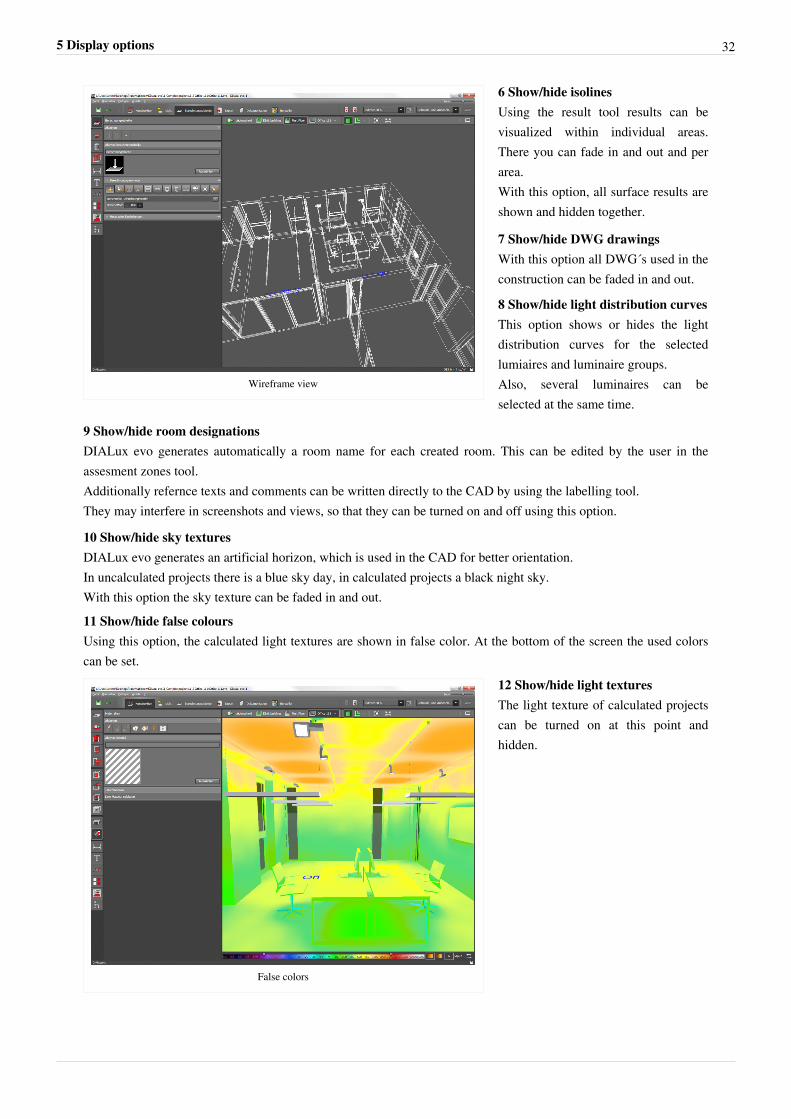
5 Display optionsIn DIALux evo it is possible to change the different display options by clicking top right on the "screen symbol".
Display options in DIALux evo
In addition the following thirteenoptions ( from the left) are available.You can activate or deactivate them byclicking on the respective symbol:1 Show/hide coordinates systemA green, a blue and a red help line isinserted.The red line corresponds tothe x-axis, the green to the y-axis andthe blue to the z-axis of the coordinatesystem. At the crossing of the lines isthe origin of the local coordinatesystem.
Each view, so site, building, storey and room has its own coordinate system.
Coordinate system
2 Show/hide help linesWith the tool "guides", various helpobjects (circle, polyline, curve, height)are generated.These have no influence on thecalculation and are a guide or as adesign aid.With the option "helplines show/ hide"they can be disabled together so theydo not interfere example in screenshotsor views on the issue.
3 Show/hide working planesEach room has initial a working plane.This can be shown or hidden by usingthis option.
4 Show/hide calculation areasCalculation surfaces and points are used to determine photometric quantities. This can be shown or hidden by usingthis option.
5 Wireframe viewSurfaces of buildings and objects are usually represented with their material color or illuminated.In case of complex objects it could be helpful to hide the filled areas, so that the surface edges are shown as lines inCAD.
5 Display options 32
Wireframe view
6 Show/hide isolinesUsing the result tool results can bevisualized within individual areas.There you can fade in and out and perarea.With this option, all surface results areshown and hidden together.
7 Show/hide DWG drawingsWith this option all DWG´s used in theconstruction can be faded in and out.
8 Show/hide light distribution curvesThis option shows or hides the lightdistribution curves for the selectedlumiaires and luminaire groups.Also, several luminaires can beselected at the same time.
9 Show/hide room designationsDIALux evo generates automatically a room name for each created room. This can be edited by the user in theassesment zones tool.Additionally refernce texts and comments can be written directly to the CAD by using the labelling tool.They may interfere in screenshots and views, so that they can be turned on and off using this option.
10 Show/hide sky texturesDIALux evo generates an artificial horizon, which is used in the CAD for better orientation.In uncalculated projects there is a blue sky day, in calculated projects a black night sky.With this option the sky texture can be faded in and out.11 Show/hide false coloursUsing this option, the calculated light textures are shown in false color. At the bottom of the screen the used colorscan be set.
False colors
12 Show/hide light texturesThe light texture of calculated projectscan be turned on at this point andhidden.
5 Display options 33
Note: After calculation the light textures are not turned on automatically. If you can´t see the light textures after the calculation,
check the settings of the display options.
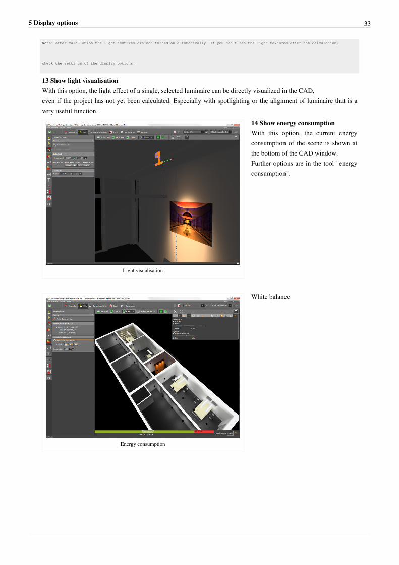
13 Show light visualisationWith this option, the light effect of a single, selected luminaire can be directly visualized in the CAD,even if the project has not yet been calculated. Especially with spotlighting or the alignment of luminaire that is avery useful function.
Light visualisation
14 Show energy consumptionWith this option, the current energyconsumption of the scene is shown atthe bottom of the CAD window.Further options are in the tool "energyconsumption".
Energy consumption
White balance
6 Keyboard Shortcuts 34
6 Keyboard Shortcuts
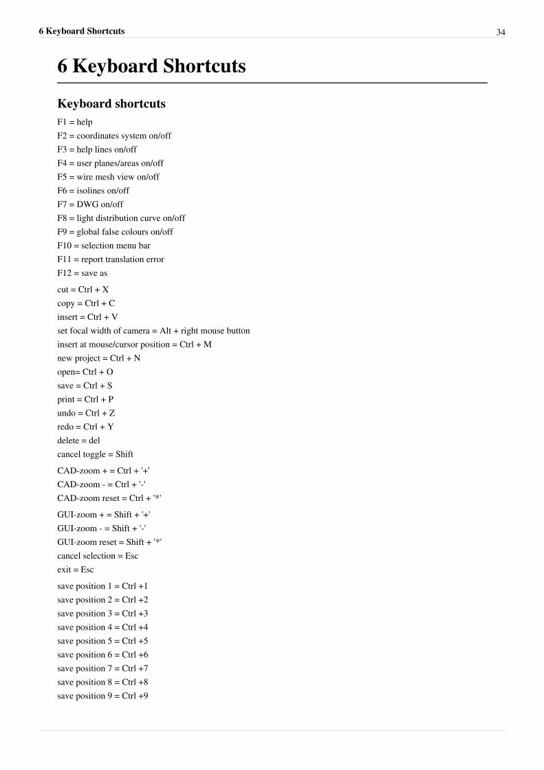
Keyboard shortcutsF1 = helpF2 = coordinates system on/offF3 = help lines on/offF4 = user planes/areas on/offF5 = wire mesh view on/offF6 = isolines on/offF7 = DWG on/offF8 = light distribution curve on/offF9 = global false colours on/offF10 = selection menu barF11 = report translation errorF12 = save ascut = Ctrl + Xcopy = Ctrl + Cinsert = Ctrl + Vset focal width of camera = Alt + right mouse buttoninsert at mouse/cursor position = Ctrl + Mnew project = Ctrl + Nopen= Ctrl + Osave = Ctrl + Sprint = Ctrl + Pundo = Ctrl + Zredo = Ctrl + Ydelete = delcancel toggle = ShiftCAD-zoom + = Ctrl + '+'CAD-zoom - = Ctrl + '-'CAD-zoom reset = Ctrl + '*'GUI-zoom + = Shift + '+'GUI-zoom - = Shift + '-'GUI-zoom reset = Shift + '*'cancel selection = Escexit = Escsave position 1 = Ctrl +1 save position 2 = Ctrl +2 save position 3 = Ctrl +3 save position 4 = Ctrl +4 save position 5 = Ctrl +5 save position 6 = Ctrl +6 save position 7 = Ctrl +7 save position 8 = Ctrl +8 save position 9 = Ctrl +9
6 Keyboard Shortcuts 35
save position 10 = Ctrl +0restore position 1 = Alt+1restore position 2 = Alt+2restore position 3 = Alt+3restore position 4 = Alt+4restore position 5 = Alt+5restore position 6 = Alt+6restore position 7 = Alt+7restore position 8 = Alt+8restore position 9 = Alt+9restore position 10 = Alt+0Control with a touchpad:Zoom = Z + left Touchpad buttonCAD Pan = P + left touchpad buttonMoving in the CAD = W, A, S, D
7 Construction of a building 36
7 Construction of a building
Construction
Drawings
Which data formats are supported?
Formats supported are DXF and DWG
Loading and displaying drawings
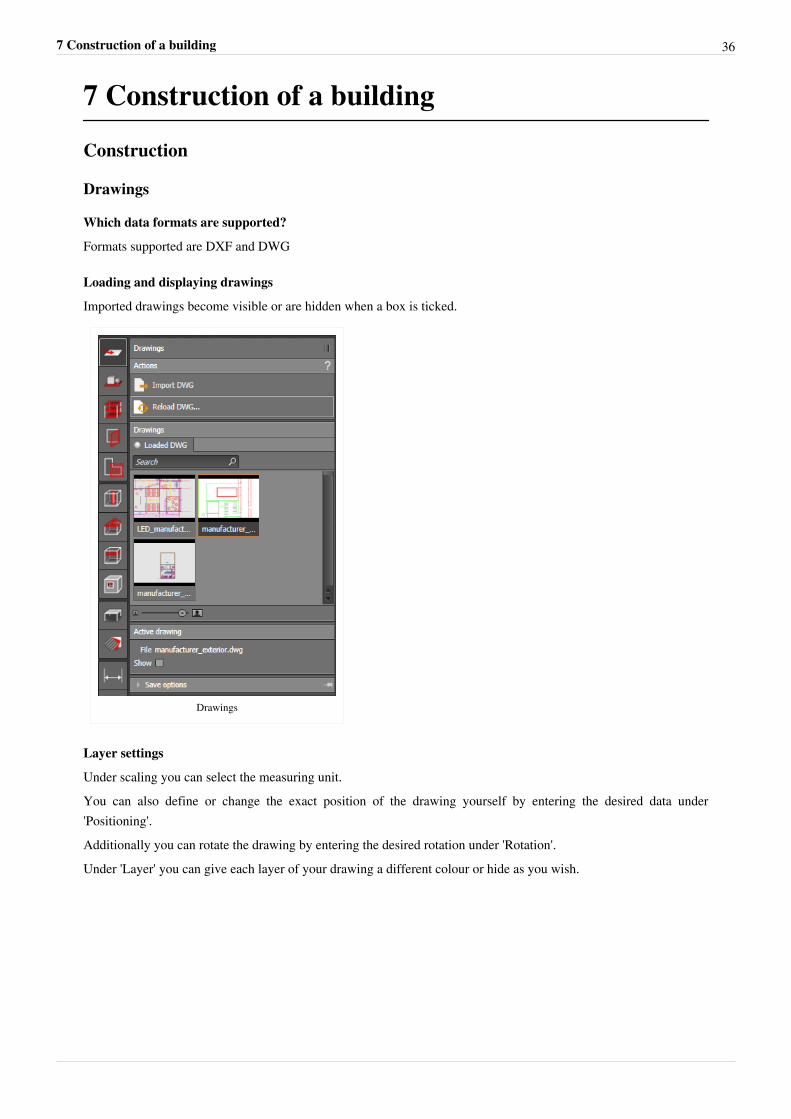
Imported drawings become visible or are hidden when a box is ticked.
Drawings
Layer settings
Under scaling you can select the measuring unit.You can also define or change the exact position of the drawing yourself by entering the desired data under'Positioning'.Additionally you can rotate the drawing by entering the desired rotation under 'Rotation'.Under 'Layer' you can give each layer of your drawing a different colour or hide as you wish.
7 Construction of a building 37
Layer
Site
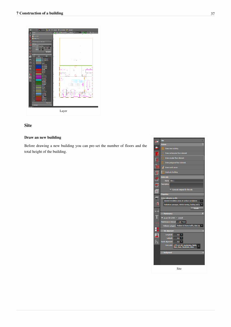
Site
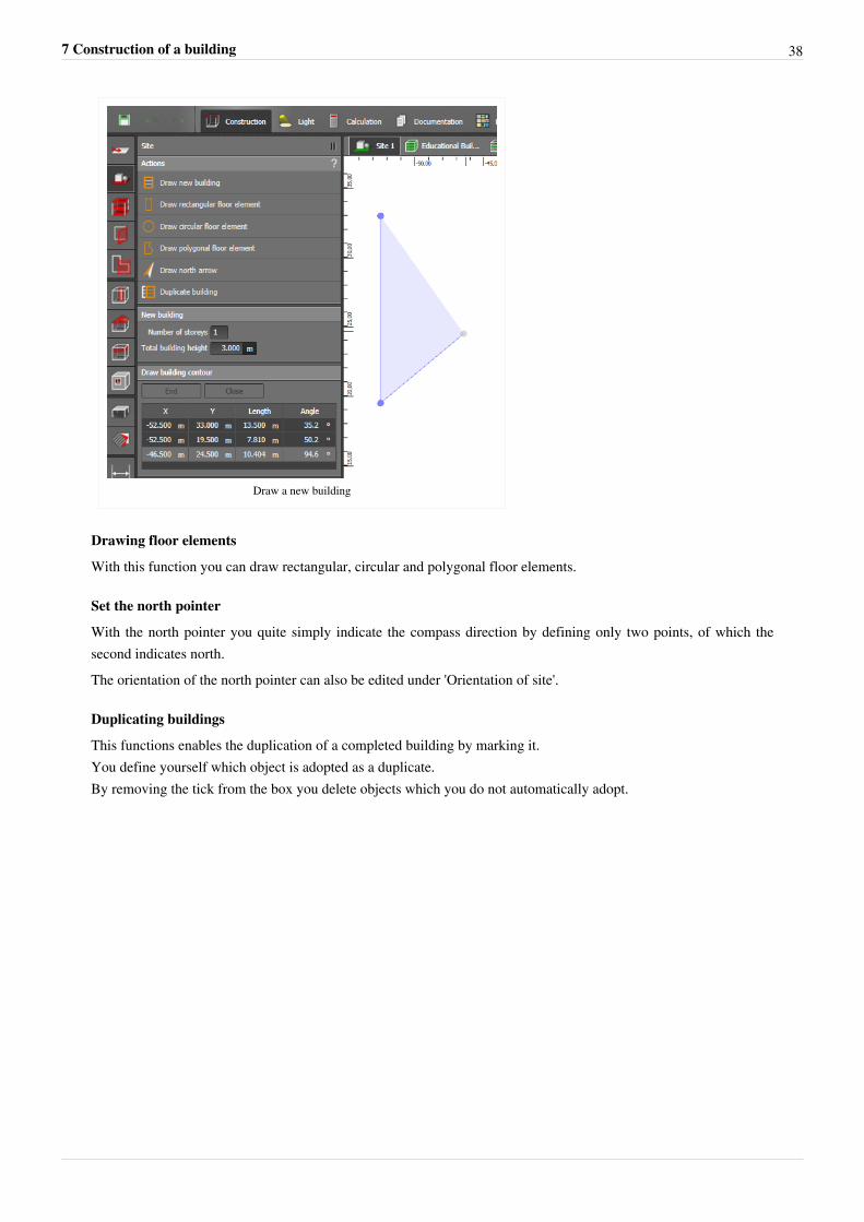
Draw an new building
Before drawing a new building you can pre-set the number of floors and thetotal height of the building.
7 Construction of a building 38
Draw a new building
Drawing floor elements
With this function you can draw rectangular, circular and polygonal floor elements.
Set the north pointer
With the north pointer you quite simply indicate the compass direction by defining only two points, of which thesecond indicates north.The orientation of the north pointer can also be edited under 'Orientation of site'.
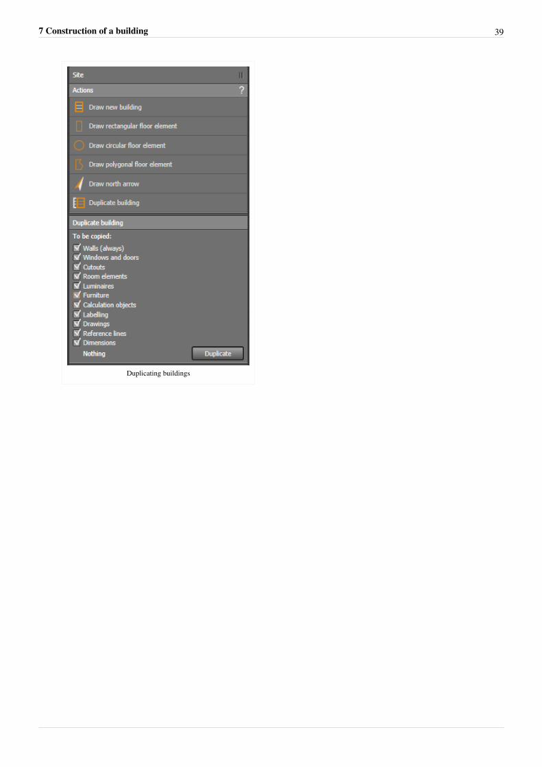
Duplicating buildings
This functions enables the duplication of a completed building by marking it.You define yourself which object is adopted as a duplicate.By removing the tick from the box you delete objects which you do not automatically adopt.
7 Construction of a building 39
Duplicating buildings
7 Construction of a building 40
Controls
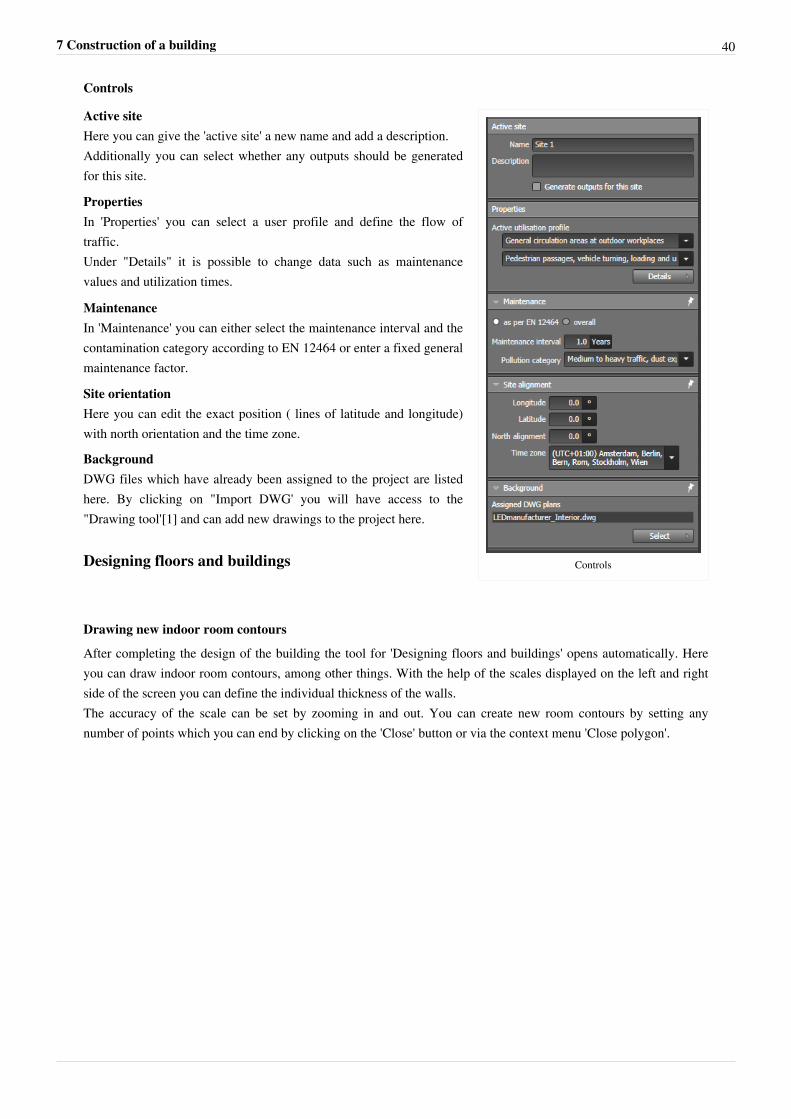
Controls
Active siteHere you can give the 'active site' a new name and add a description.Additionally you can select whether any outputs should be generatedfor this site.
PropertiesIn 'Properties' you can select a user profile and define the flow oftraffic.Under "Details" it is possible to change data such as maintenancevalues and utilization times.
MaintenanceIn 'Maintenance' you can either select the maintenance interval and thecontamination category according to EN 12464 or enter a fixed generalmaintenance factor.
Site orientationHere you can edit the exact position ( lines of latitude and longitude)with north orientation and the time zone.
BackgroundDWG files which have already been assigned to the project are listedhere. By clicking on "Import DWG' you will have access to the"Drawing tool'[1] and can add new drawings to the project here.
Designing floors and buildings
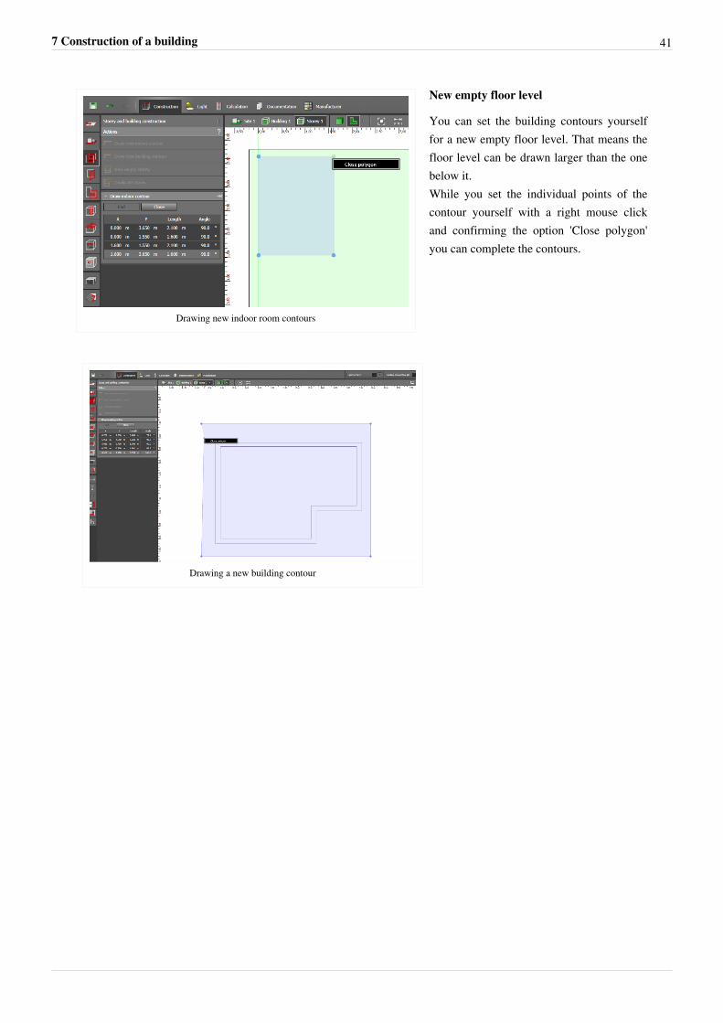
Drawing new indoor room contours
After completing the design of the building the tool for 'Designing floors and buildings' opens automatically. Hereyou can draw indoor room contours, among other things. With the help of the scales displayed on the left and rightside of the screen you can define the individual thickness of the walls.The accuracy of the scale can be set by zooming in and out. You can create new room contours by setting anynumber of points which you can end by clicking on the 'Close' button or via the context menu 'Close polygon'.
7 Construction of a building 41
Drawing new indoor room contours
New empty floor level
You can set the building contours yourselffor a new empty floor level. That means thefloor level can be drawn larger than the onebelow it.While you set the individual points of thecontour yourself with a right mouse clickand confirming the option 'Close polygon'you can complete the contours.
Drawing a new building contour
7 Construction of a building 42
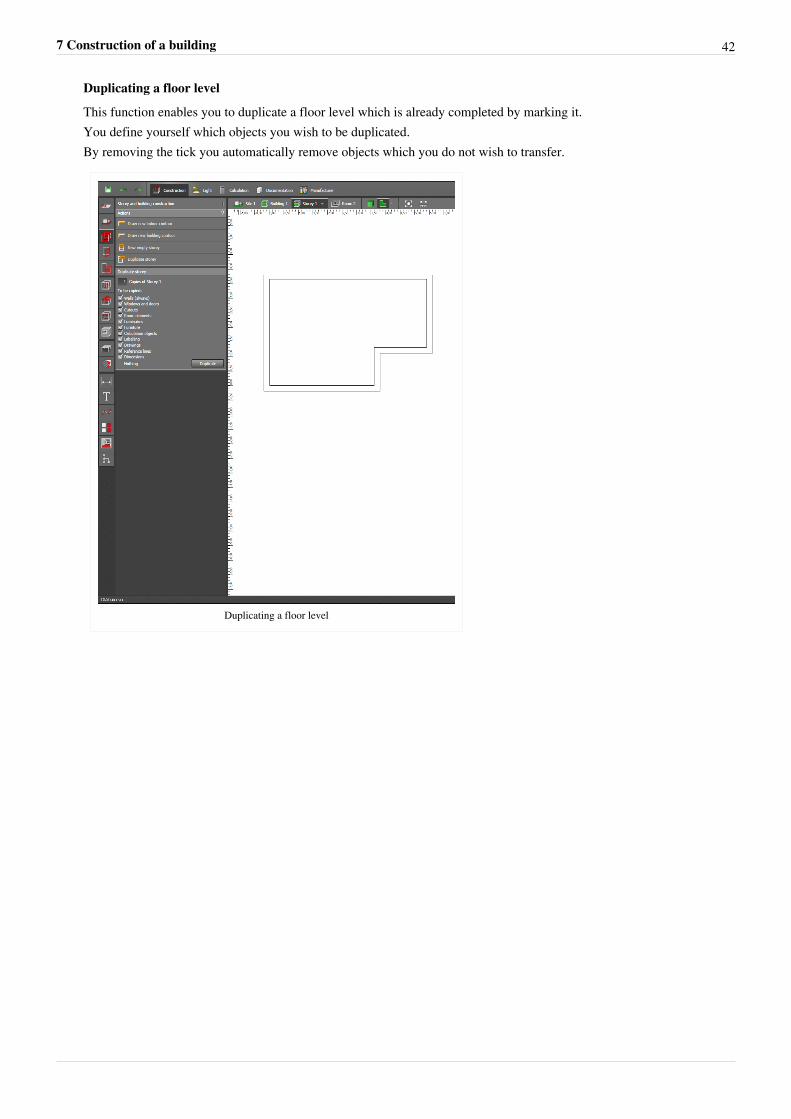
Duplicating a floor level
This function enables you to duplicate a floor level which is already completed by marking it.You define yourself which objects you wish to be duplicated.By removing the tick you automatically remove objects which you do not wish to transfer.
Duplicating a floor level
7 Construction of a building 43
Building apertures
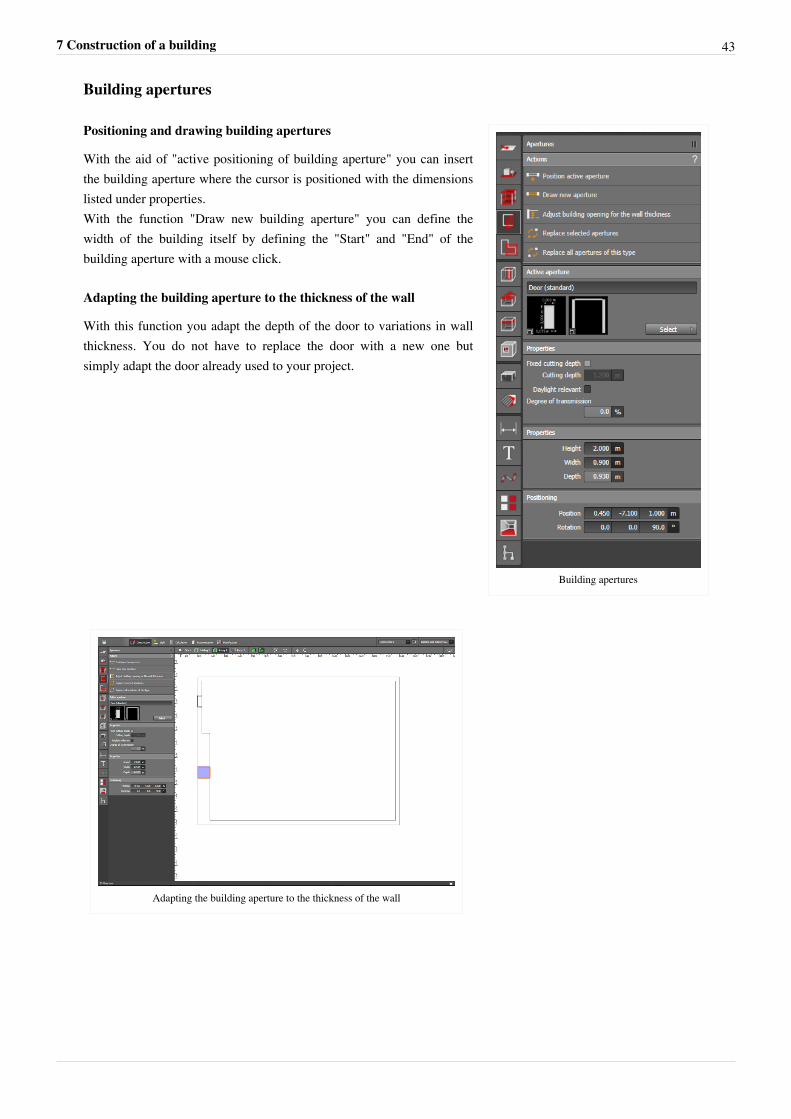
Building apertures
Positioning and drawing building apertures
With the aid of "active positioning of building aperture" you can insertthe building aperture where the cursor is positioned with the dimensionslisted under properties.With the function "Draw new building aperture" you can define thewidth of the building itself by defining the "Start" and "End" of thebuilding aperture with a mouse click.
Adapting the building aperture to the thickness of the wall
With this function you adapt the depth of the door to variations in wallthickness. You do not have to replace the door with a new one butsimply adapt the door already used to your project.
Adapting the building aperture to the thickness of the wall
7 Construction of a building 44
Exchanging selected / all building apertures of one type
With this function you can exchange one or several building apertures in one step.You select the building apertures you wish to exchange and then select "Exchange selected/all building apertures ofthis type".If you wish to exchange only one building aperture among many in the project, then select "Exchange selectedbuilding apertures".If, however, you wish to exchange every single one of these building apertures which appear in the project, select"Exchange all building apertures of the same type".Then a window will open in which you can select the new building aperture.After selecting the new building aperture, this will be inserted automatically into your building.
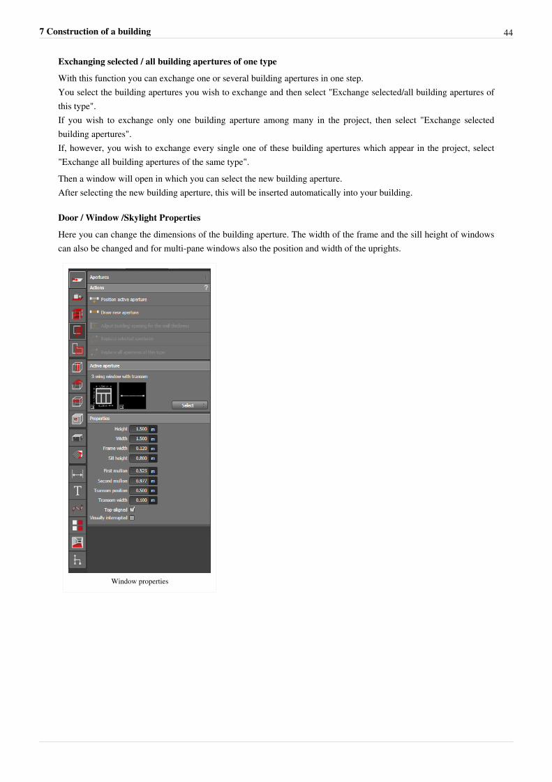
Door / Window /Skylight Properties
Here you can change the dimensions of the building aperture. The width of the frame and the sill height of windowscan also be changed and for multi-pane windows also the position and width of the uprights.
Window properties
7 Construction of a building 45
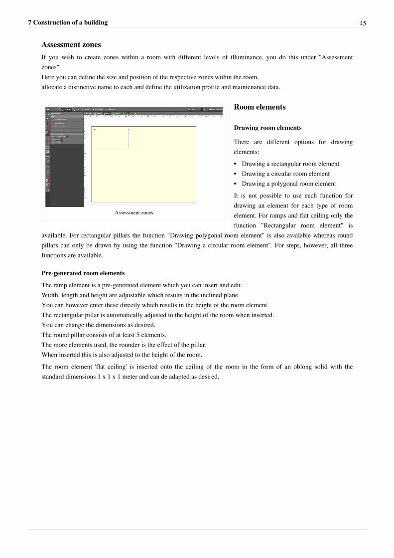
Assessment zonesIf you wish to create zones within a room with different levels of illuminance, you do this under "Assessmentzones".Here you can define the size and position of the respective zones within the room,allocate a distinctive name to each and define the utilization profile and maintenance data.
Assessment zones
Room elements
Drawing room elements
There are different options for drawingelements:•• Drawing a rectangular room element•• Drawing a circular room element•• Drawing a polygonal room elementIt is not possible to use each function fordrawing an element for each type of roomelement. For ramps and flat ceiling only thefunction "Rectangular room element" is
available. For rectangular pillars the function "Drawing polygonal room element" is also available whereas roundpillars can only be drawn by using the function "Drawing a circular room element". For steps, however, all threefunctions are available.
Pre-generated room elements
The ramp element is a pre-generated element which you can insert and edit.Width, length and height are adjustable which results in the inclined plane.You can however enter these directly which results in the height of the room element.The rectangular pillar is automatically adjusted to the height of the room when inserted.You can change the dimensions as desired.The round pillar consists of at least 5 elements.The more elements used, the rounder is the effect of the pillar.When inserted this is also adjusted to the height of the room.The room element 'flat ceiling' is inserted onto the ceiling of the room in the form of an oblong solid with thestandard dimensions 1 x 1 x 1 meter and can de adapted as desired.
7 Construction of a building 46
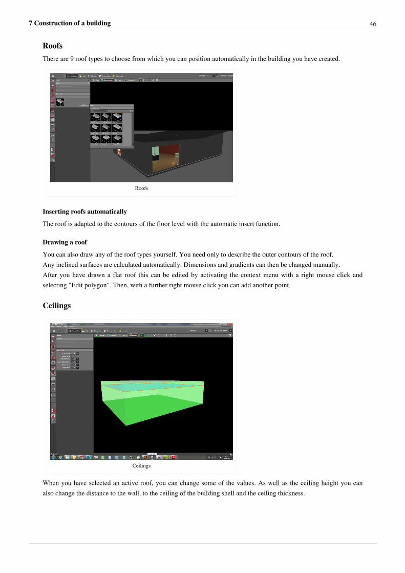
RoofsThere are 9 roof types to choose from which you can position automatically in the building you have created.
Roofs
Inserting roofs automatically
The roof is adapted to the contours of the floor level with the automatic insert function.
Drawing a roof
You can also draw any of the roof types yourself. You need only to describe the outer contours of the roof.Any inclined surfaces are calculated automatically. Dimensions and gradients can then be changed manually.After you have drawn a flat roof this can be edited by activating the context menu with a right mouse click andselecting "Edit polygon". Then, with a further right mouse click you can add another point.
Ceilings
Ceilings
When you have selected an active roof, you can change some of the values. As well as the ceiling height you canalso change the distance to the wall, to the ceiling of the building shell and the ceiling thickness.
7 Construction of a building 47
Inserting a ceiling in a room
With this function a suspended ceiling can also be inserted over the whole room.
Drawing a new ceiling
You can also draw the ceiling yourself and adjust its size and position as you wish.
Furniture and Objects
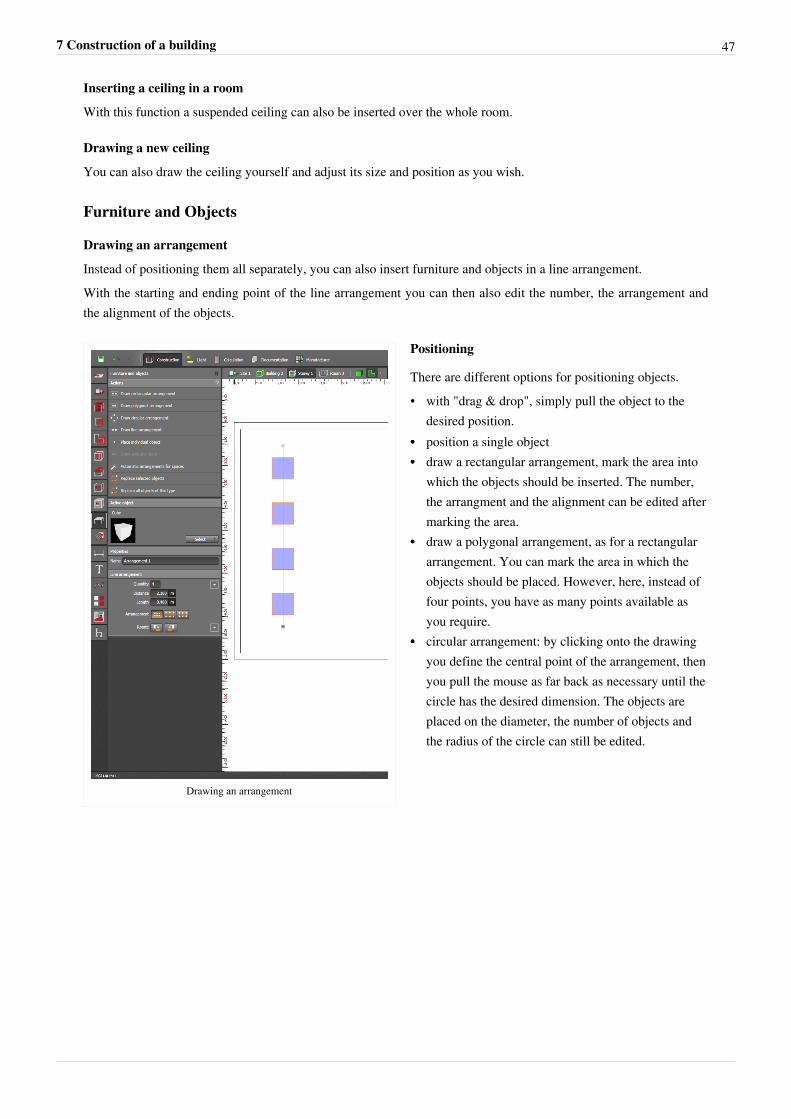
Drawing an arrangement
Instead of positioning them all separately, you can also insert furniture and objects in a line arrangement.With the starting and ending point of the line arrangement you can then also edit the number, the arrangement andthe alignment of the objects.
Drawing an arrangement
Positioning
There are different options for positioning objects.• with "drag & drop", simply pull the object to the
desired position.•• position a single object•• draw a rectangular arrangement, mark the area into
which the objects should be inserted. The number,the arrangment and the alignment can be edited aftermarking the area.
•• draw a polygonal arrangement, as for a rectangulararrangement. You can mark the area in which theobjects should be placed. However, here, instead offour points, you have as many points available asyou require.
•• circular arrangement: by clicking onto the drawingyou define the central point of the arrangement, thenyou pull the mouse as far back as necessary until thecircle has the desired dimension. The objects areplaced on the diameter, the number of objects andthe radius of the circle can still be edited.
7 Construction of a building 48
Positioning
Exchanging selected / all objects of onetype
This function allows you to exchangeseveral objects at one time. If, for example,you have placed an office chair in each ofthe rooms in your project, by using thefunction "Exchange all objects of the sametype" you can replace one chair by another.If you wish to exchange the chairs in onespecific room only, then you mark the chairsund use the function "Exchange selectedobjects".
Object catalogue
In DIALux evo, as in DIALux 4, there arestandard objects and an object cataloguewhich can be started in " Furniture andobject tool" in the design mode.
Objects/furniture can be added to the DIALux evo database either via "drag & drop" directly into the project or byclicking on "Adopt".
By clicking on an object you can add this to your 'Favourites'.The objects used in your project are found at the top of the list. In addition the number of each object occurring inthe project is displayed.
Materials
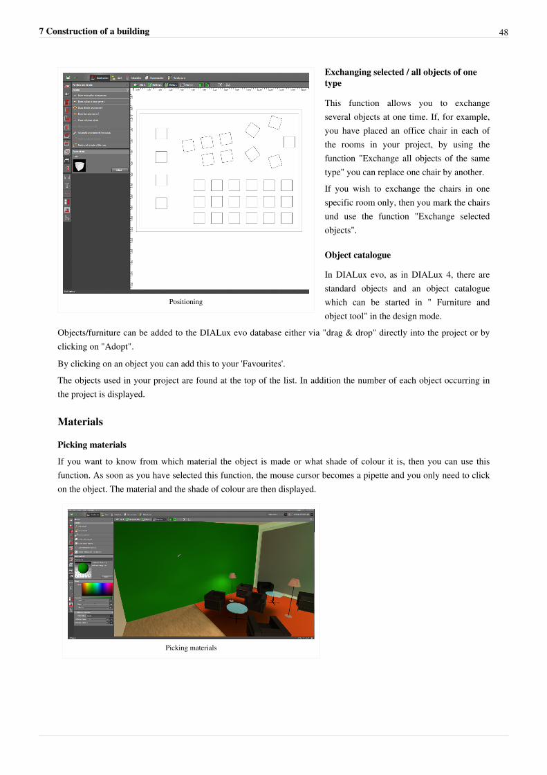
Picking materials
If you want to know from which material the object is made or what shade of colour it is, then you can use thisfunction. As soon as you have selected this function, the mouse cursor becomes a pipette and you only need to clickon the object. The material and the shade of colour are then displayed.
Picking materials
7 Construction of a building 49
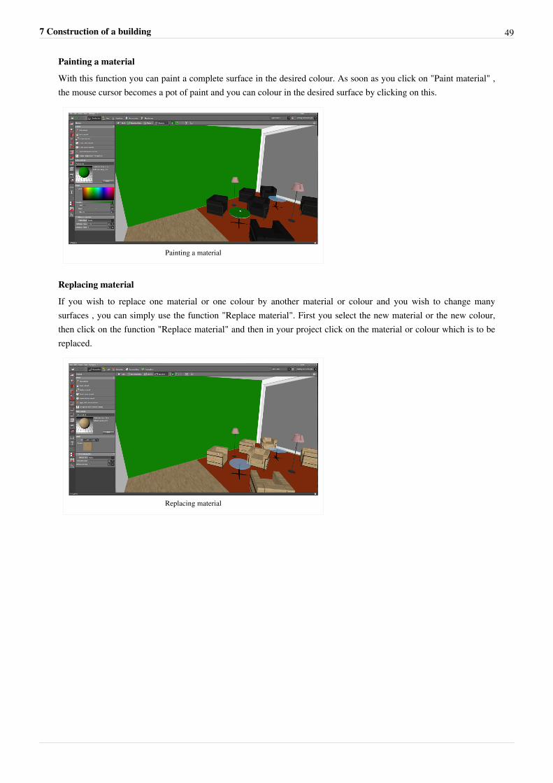
Painting a material
With this function you can paint a complete surface in the desired colour. As soon as you click on "Paint material" ,the mouse cursor becomes a pot of paint and you can colour in the desired surface by clicking on this.
Painting a material
Replacing material
If you wish to replace one material or one colour by another material or colour and you wish to change manysurfaces , you can simply use the function "Replace material". First you select the new material or the new colour,then click on the function "Replace material" and then in your project click on the material or colour which is to bereplaced.
Replacing material
7 Construction of a building 50
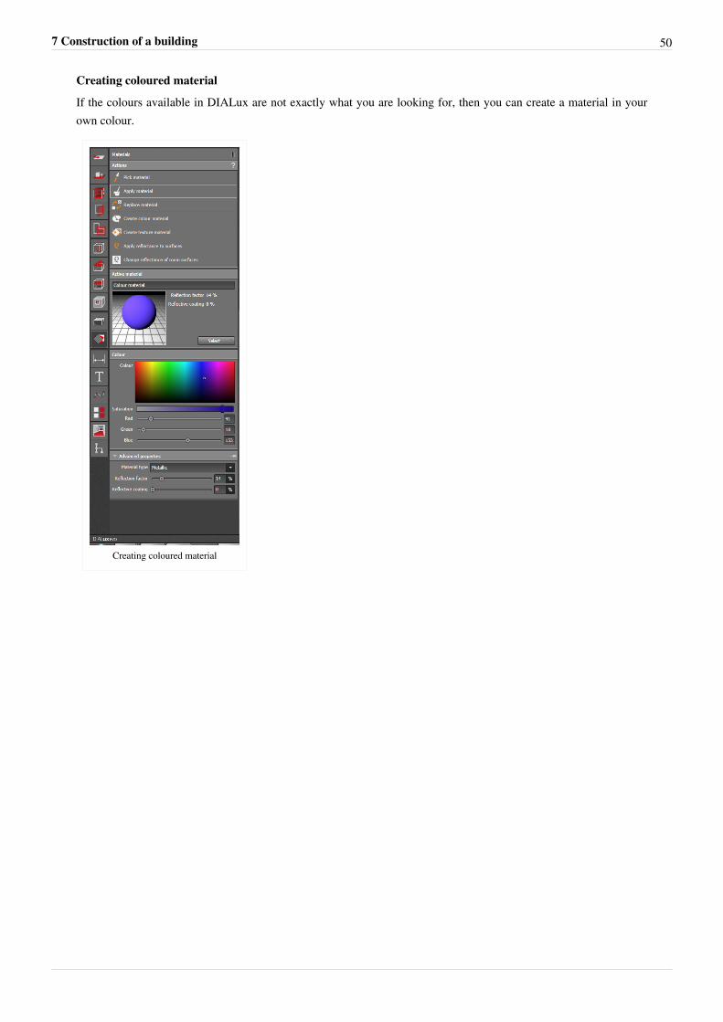
Creating coloured material
If the colours available in DIALux are not exactly what you are looking for, then you can create a material in yourown colour.
Creating coloured material
7 Construction of a building 51
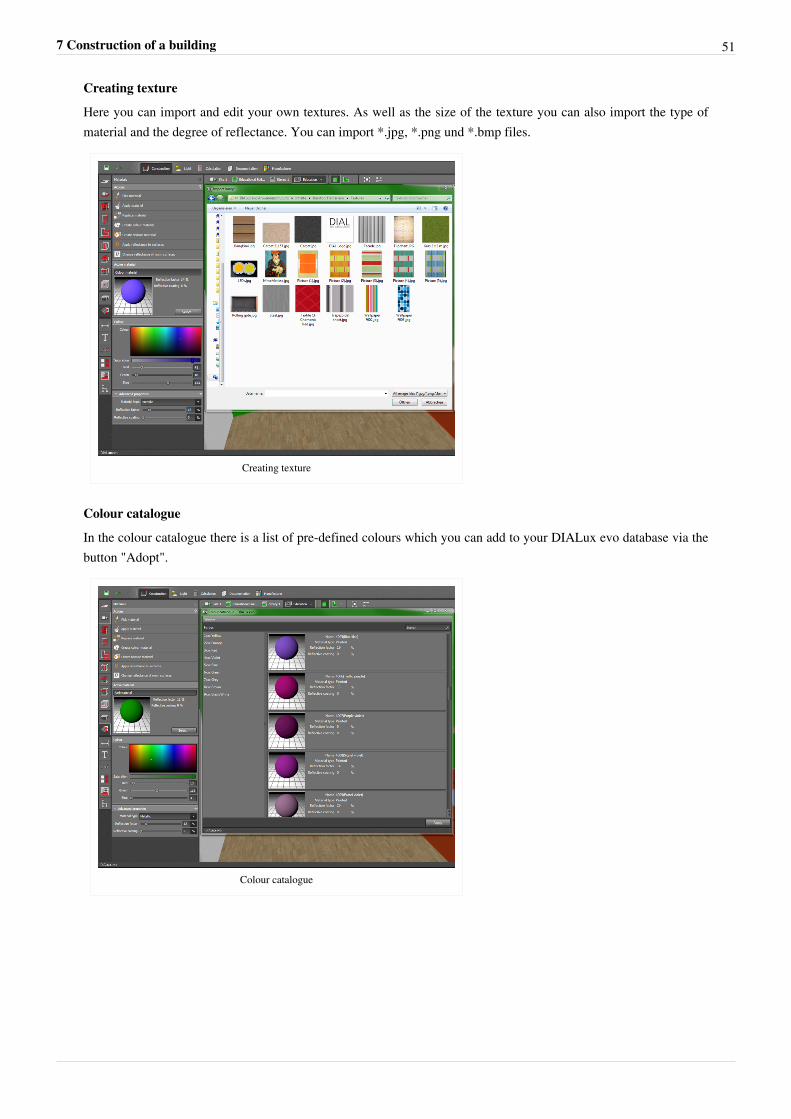
Creating texture
Here you can import and edit your own textures. As well as the size of the texture you can also import the type ofmaterial and the degree of reflectance. You can import *.jpg, *.png und *.bmp files.
Creating texture
Colour catalogue
In the colour catalogue there is a list of pre-defined colours which you can add to your DIALux evo database via thebutton "Adopt".
Colour catalogue
7 Construction of a building 52
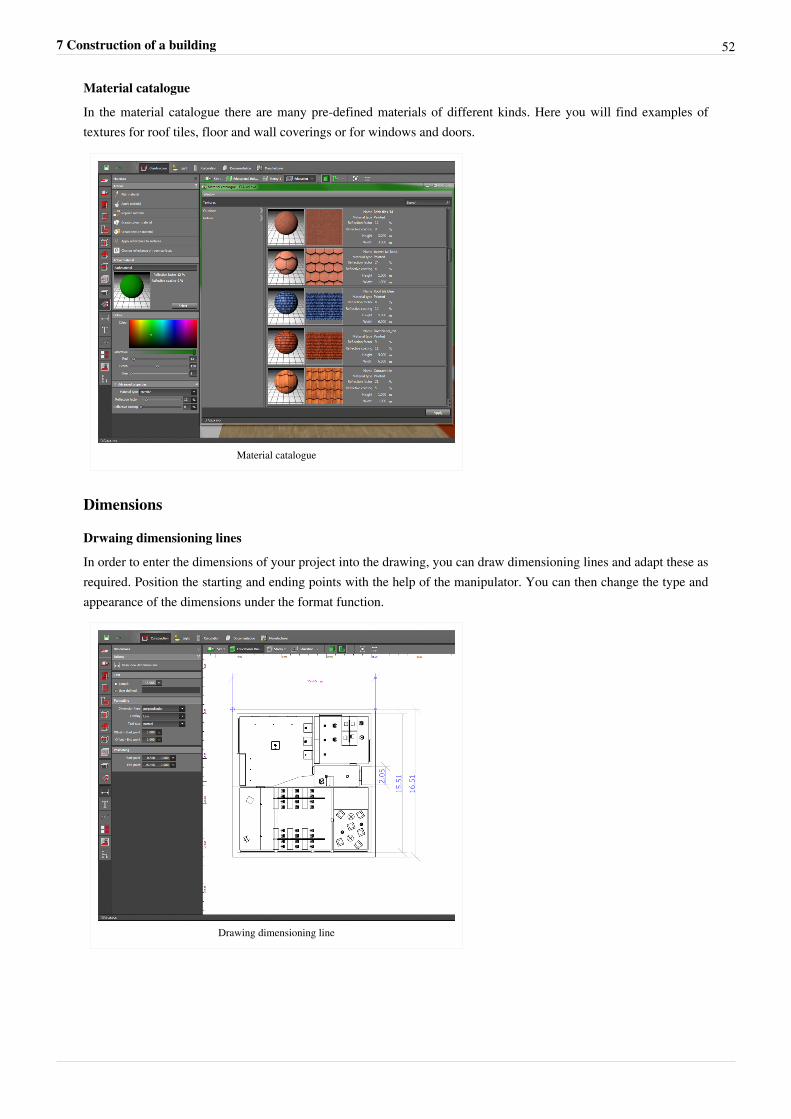
Material catalogue
In the material catalogue there are many pre-defined materials of different kinds. Here you will find examples oftextures for roof tiles, floor and wall coverings or for windows and doors.
Material catalogue
Dimensions
Drwaing dimensioning lines
In order to enter the dimensions of your project into the drawing, you can draw dimensioning lines and adapt these asrequired. Position the starting and ending points with the help of the manipulator. You can then change the type andappearance of the dimensions under the format function.
Drawing dimensioning line
7 Construction of a building 53
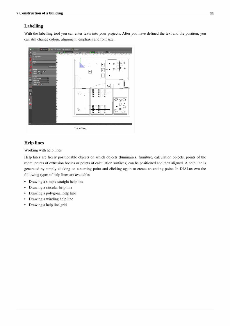
LabellingWith the labelling tool you can enter texts into your projects. After you have defined the text and the position, youcan still change colour, alignment, emphasis and font size.
Labelling
Help linesWorking with help linesHelp lines are freely positionable objects on which objects (luminaires, furniture, calculation objects, points of theroom, points of extrusion bodies or points of calculation surfaces) can be positioned and then aligned. A help line isgenerated by simply clicking on a starting point and clicking again to create an ending point. In DIALux evo thefollowing types of help lines are available:•• Drawing a simple straight help line•• Drawing a circular help line•• Drawing a polygonal help line•• Drawing a winding help line•• Drawing a help line grid
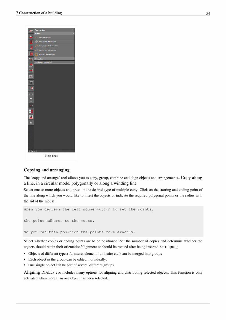
7 Construction of a building 54
Help lines
Copying and arranging
The "copy and arrange" tool allows you to copy, group, combine and align objects and arrangements.. Copy alonga line, in a circular mode, polygonally or along a winding lineSelect one or more objects and press on the desired type of multiple copy. Click on the starting and ending point ofthe line along which you would like to insert the objects or indicate the required polygonal points or the radius withthe aid of the mouse.
When you depress the left mouse button to set the points,
the point adheres to the mouse.
So you can then position the points more exactly.
Select whether copies or ending points are to be positioned. Set the number of copies and determine whether theobjects should retain their orientation/alignment or should be rotated after being inserted. Grouping•• Objects of different types( furniture, element, luminaire etc.) can be merged into groups•• Each object in the group can be edited individually.•• One single object can be part of several different groups.
Aligning DIALux evo includes many options for aligning and distributing selected objects. This function is onlyactivated when more than one object has been selected.
7 Construction of a building 55
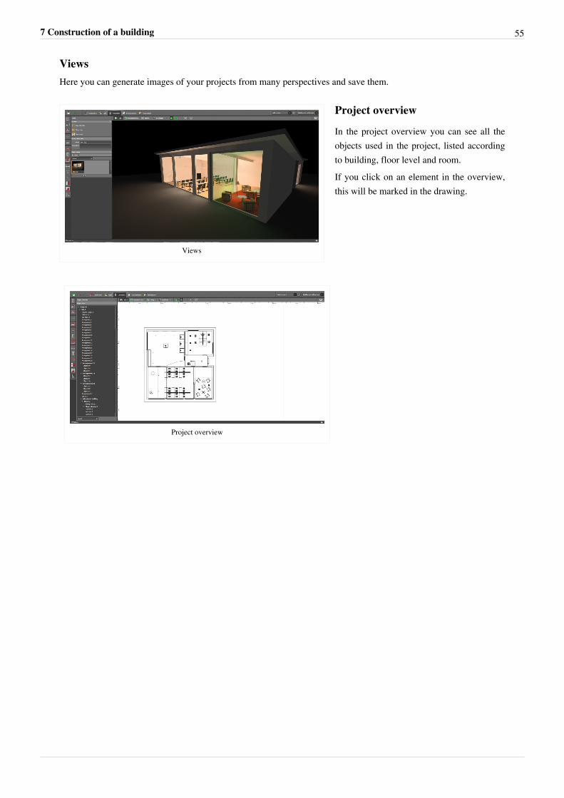
ViewsHere you can generate images of your projects from many perspectives and save them.
Views
Project overview
In the project overview you can see all theobjects used in the project, listed accordingto building, floor level and room.If you click on an element in the overview,this will be marked in the drawing.
Project overview
8 Light 56
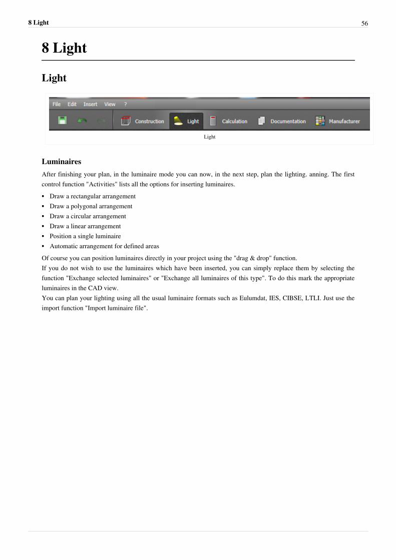
8 Light
Light
Light
LuminairesAfter finishing your plan, in the luminaire mode you can now, in the next step, plan the lighting. anning. The firstcontrol function "Activities" lists all the options for inserting luminaires.•• Draw a rectangular arrangement•• Draw a polygonal arrangement•• Draw a circular arrangement•• Draw a linear arrangement•• Position a single luminaire•• Automatic arrangement for defined areasOf course you can position luminaires directly in your project using the "drag & drop" function.If you do not wish to use the luminaires which have been inserted, you can simply replace them by selecting thefunction "Exchange selected luminaires" or "Exchange all luminaires of this type". To do this mark the appropriateluminaires in the CAD view.You can plan your lighting using all the usual luminaire formats such as Eulumdat, IES, CIBSE, LTLI. Just use theimport function "Import luminaire file".
8 Light 57
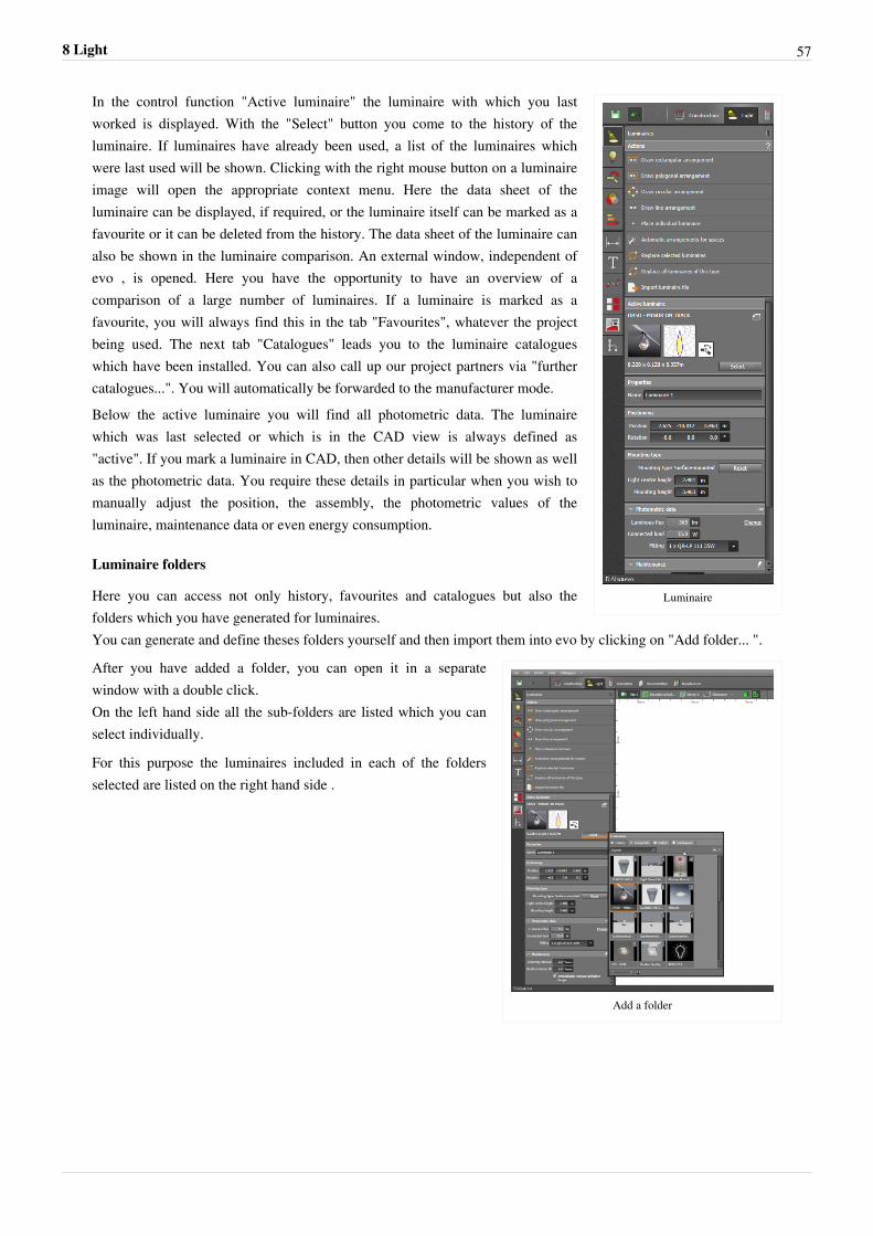
Luminaire
In the control function "Active luminaire" the luminaire with which you lastworked is displayed. With the "Select" button you come to the history of theluminaire. If luminaires have already been used, a list of the luminaires whichwere last used will be shown. Clicking with the right mouse button on a luminaireimage will open the appropriate context menu. Here the data sheet of theluminaire can be displayed, if required, or the luminaire itself can be marked as afavourite or it can be deleted from the history. The data sheet of the luminaire canalso be shown in the luminaire comparison. An external window, independent ofevo , is opened. Here you have the opportunity to have an overview of acomparison of a large number of luminaires. If a luminaire is marked as afavourite, you will always find this in the tab "Favourites", whatever the projectbeing used. The next tab "Catalogues" leads you to the luminaire catalogueswhich have been installed. You can also call up our project partners via "furthercatalogues...". You will automatically be forwarded to the manufacturer mode.Below the active luminaire you will find all photometric data. The luminairewhich was last selected or which is in the CAD view is always defined as"active". If you mark a luminaire in CAD, then other details will be shown as wellas the photometric data. You require these details in particular when you wish tomanually adjust the position, the assembly, the photometric values of theluminaire, maintenance data or even energy consumption.
Luminaire folders
Here you can access not only history, favourites and catalogues but also thefolders which you have generated for luminaires.You can generate and define theses folders yourself and then import them into evo by clicking on "Add folder... ".
Add a folder
After you have added a folder, you can open it in a separatewindow with a double click.On the left hand side all the sub-folders are listed which you canselect individually.
For this purpose the luminaires included in each of the foldersselected are listed on the right hand side .
8 Light 58
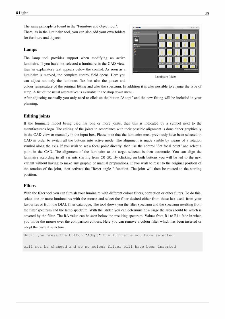
Luminaire folder
The same principle is found in the "Furniture and object tool".There, as in the luminaire tool, you can also add your own foldersfor furniture and objects.
Lamps
The lamp tool provides support when modifying an activeluminaire. If you have not selected a luminaire in the CAD view,then an explanatory text appears below the control. As soon as aluminaire is marked, the complete control field opens. Here youcan adjust not only the luminous flux but also the power andcolour temperature of the original fitting and also the spectrum. In addition it is also possible to change the type oflamp. A list of the usual alternatives is available in the drop down menu.After adjusting manually you only need to click on the button "Adopt" and the new fitting will be included in yourplanning.
Editing jointsIf the luminaire model being used has one or more joints, then this is indicated by a symbol next to themanufacturer's logo. The editing of the joints in accordance with their possible alignment is done either graphicallyin the CAD view or manually in the input box. Please note that the lumianire must previously have been selected inCAD in order to switch all the buttons into active mode. The alignment is made visible by means of a rotationsymbol along the axis. If you wish to set a focal point directly, then use the control "Set focal point" and select apoint in the CAD. The alignment of the luminaire to the target selected is then automatic. You can align theluminaire according to all variants starting from C0 G0. By clicking on both buttons you will be led to the nextvariant without having to make any graphic or manual preparations. If you wish to reset to the original position ofthe rotation of the joint, then activate the "Reset angle " function. The joint will then be rotated to the startingposition.
FiltersWith the filter tool you can furnish your luminaire with different colour filters, correction or other filters. To do this,select one or more luminnaires with the mouse and select the filter desired either from those last used, from yourfavourites or from the DIAL filter catalogue. The tool shows you the filter spectrum and the spectrum resulting fromthe filter spectrum and the lamp spectrum. With the 'slider' you can determine how large the area should be which iscovered by the filter. The RA value can be seen below the resulting spectrum. Values from R1 to R14 fade in whenyou move the mouse over the comparison colours. Here you can remove a colour filter which has been inserted oradopt the current selection.
Until you press the button "Adopt" the luminaire you have selected
will not be changed and so no colour filter will have been inserted.
8 Light 59
Lighting scenes
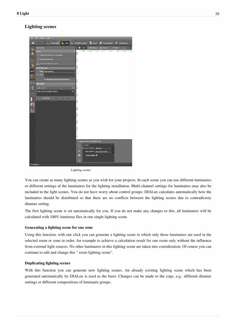
Lighting scenes
You can create as many lighting scenes as you wish for your projects. In each scene you can use different luminairesor different settings of the luminaires for the lighting installation. Multi-channel settings for luminaires may also beincluded in the light scenes. You do not have worry about control groups: DIALux calculates automatically how theluminaires should be distributed so that there are no conflicts between the lighting scenes due to contradictorydimmer setting.The first lighting scene is set automatically for you. If you do not make any changes to this, all luminaires will becalculated with 100% luminous flux in one single lighting scene.
Generating a lighting scene for one zone
Using this function, with one click you can generate a lighting scene in which only those luminaires are used in theselected room or zone in order, for example to achieve a calculation result for one room only without the influencefrom external light sources. No other luminaires in this lighting scene are taken into consideration. Of course you cancontinue to edit and change this " room lighting scene".
Duplicating lighting scenes
With this function you can generate new lighting scenes. An already existing lighting scene which has beengenerated automatically by DIALux is used as the basis. Changes can be made to the copy, e.g.. different dimmersettings or different compositions of luminaire groups.
8 Light 60
Generating new luminaire groups
Luminaire groups are luminaires which are switched on and off or are dimmed together or which have commonchannel settings. Just mark the luminaires concerned and press "Generate new luminaire group". A luminaire cannotbelong to various luminaire groups. since this might lead to contradictory switching or dimming conditions. If youtry to allot a luminiare to a second luminaire group within the lighting scenes, the function will be deactivated. Inthis case you must first remove the luminaire from the old luminaire group. To do this, select the luminaire and clickwithin the luminaire group on the small minus symbol below the CAD. In the same way you can add a luminaire to aluminaire group.
Active lighting scene
Here you can edit the name and description of the lighting scene.
For larger projects it is of great benefit to allocate names to the
lighting scenes, e.g. "all on", "presentation", "pause", etc.
That makes switching around and finding again much easier.
With the checkbox "Generate output for this lighting scene" you decide whether all the calculation results of thislighting scene should appear in the outputs. Especially when many lighting scenes have been generated forpresentation purposes it does not always make sense to create all the outputs possible.
Lighting scenes
All the lighting scenes created are listed here. They can be called up with a double click. Alternatively you canrearrange the lighting scenes at the top of the window and activate them with the button next to them. The creation oflighting textures for CAD may take a few moments. Room lighting scenes are marked with (S).
New luminaires are always inserted first into the active lighting scene.
Here it is possible to combine lighting scenes which makes sense e.g.for room lighting scenes. Instead of generatingthree room lighting scenes and all the combinations of the different lighting scenes, you now need only the threeroom lighting scenes. With the help of the check boxes these can be combined and visualised. If required, acombination of lighting scenes can be saved as a new lighting scene e.g.to be used in the documentation.Luminaire groups of lighting scenes. Here all the luminaire groups of the active lighting scene are listed. You candelete (-) or add (+) luminaires from or to the groups, rename or delete the group or set the luminous fluxpercentually. With multi-channel luminaires each channel can be set separately. On the right hand side you can seethe symbols for:•• updating each of the lighting scenes•• setting all the luminaires together to 100% luminous flux•• setting all together to 0%•• combining luminaire goups with the same dimming values into one new luminaire group.
Energy consumptionIn the course of your planning you acquire an overview of how high the current energy consumption of your installation is or how much energy can be saved. To do this select the option "Display energy tachometer" in [Light-> Properties tachometer] or select the appropriate option in display options. In addition you can set whether the LENI(kWh/a/m2) value, the energy consumption (kWh/a) or the costs should be displayed in the tachometer. In all displays it is possible to set a limit which then becomes a limit value in the tachometer. For the costs you can also
8 Light 61
select a currency. In the energy tool all three values are displayed next to each other. In the energy tool an energysensor can also be inserted which takes into account energy saving according to EN 15193. Indicate whetherconstant lighting control is available and what kind of presence sensors are used. The energy tacho itself can be seenbelow the CAD window until it is deactivated by the user. The tachometer can either take into account the wholeproject("Whole") or only the current scene visible in the CAD window ("Current scene"). In this way it is possible toevaluate and plan single rooms or floor levels. The tachometer also displays the spectrum of possible energy savingthrough daylight which is why the display shows a minimal value for maximum saving through daylight and amaximum value without saving through daylight. Calculation is in accordance with EN 15193.Data for the period of use of light are gathered from the user profile which you can set for each area. Thegeographical and geometrical information is gathered from the project itself.
Remember to indicate latitude and longitude in the site tool.
This information is necessary for calculation according to EN 15193.
DaylightDaylight
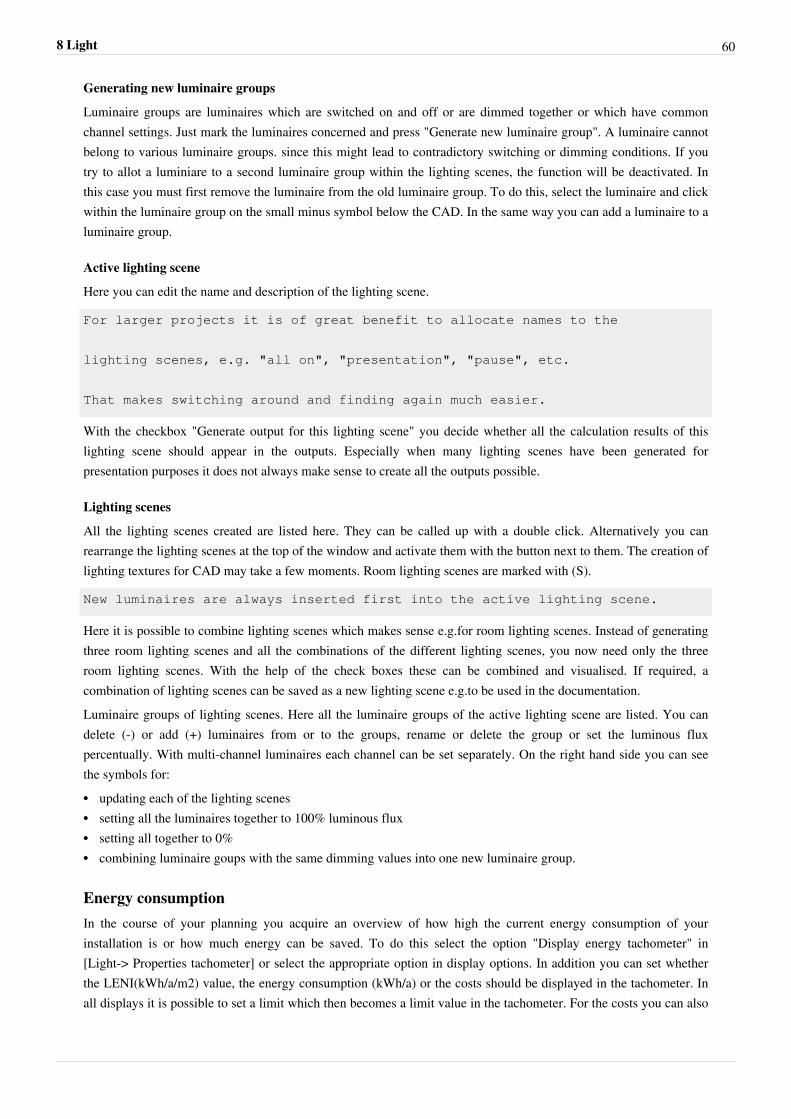
9 Start CalculationWith the evo 4, the calculation tool was removed from its mode and integrated into the header.This makes it possible to start the calculation at any time, regardless of the current view and recently performedsteps.By default, the buttons are disabledThey are activated as soon as DIALux recognizes that a calculation is possible, that is, either because:•• in the light scene tool the reference sky type is not "no daylight" and in addition a window exists.•• a luminaire is available in the project.
Start calculation
While calculating the button changesfrom "Start calculation" to "Cancelcalculation"
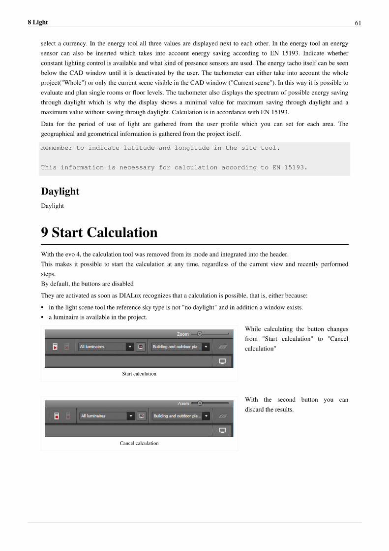
Cancel calculation
With the second button you candiscard the results.
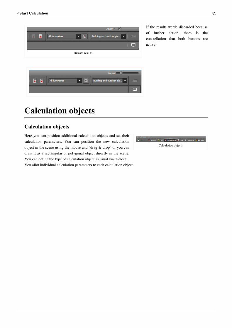
9 Start Calculation 62
Discard results
If the results werde discarded becauseof further action, there is theconstellation that both buttons areactive.
Calculation objects
Calculation objects
Calculation objects
Here you can position additional calculation objects and set theircalculation parameters. You can position the new calculationobject in the scene using the mouse and "drag & drop" or you candraw it as a rectangular or polygonal object directly in the scene.You can define the type of calculation object as usual via "Select".You allot individual calculation parameters to each calculation object.
Calculation objects 63
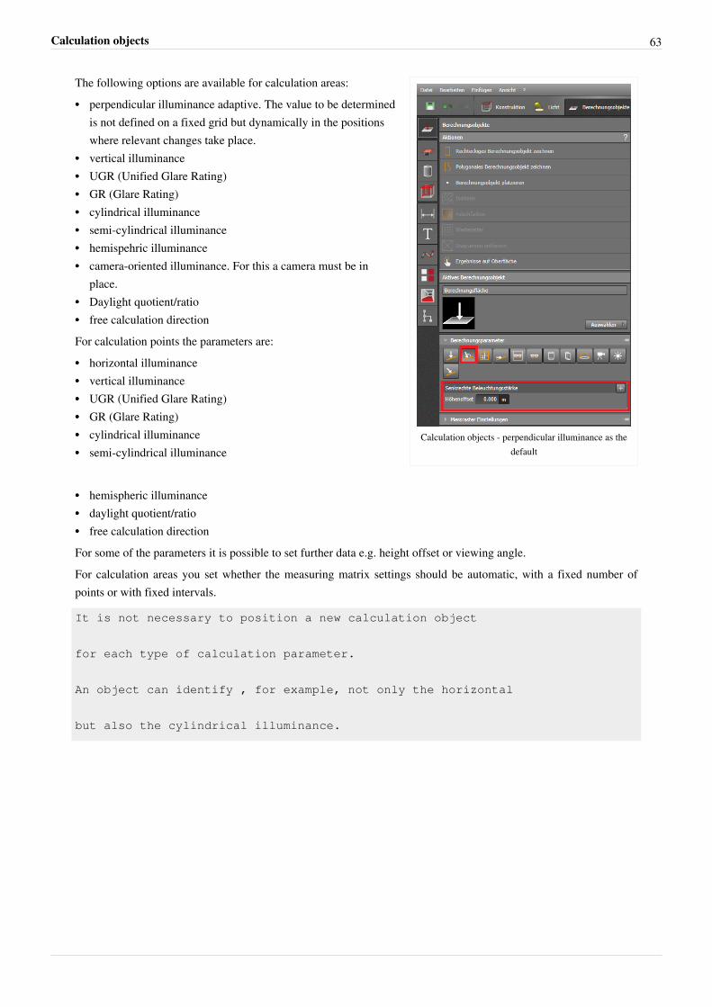
Calculation objects - perpendicular illuminance as thedefault
The following options are available for calculation areas:•• perpendicular illuminance adaptive. The value to be determined
is not defined on a fixed grid but dynamically in the positionswhere relevant changes take place.
•• vertical illuminance•• UGR (Unified Glare Rating)•• GR (Glare Rating)•• cylindrical illuminance•• semi-cylindrical illuminance•• hemispehric illuminance•• camera-oriented illuminance. For this a camera must be in
place.•• Daylight quotient/ratio•• free calculation directionFor calculation points the parameters are:•• horizontal illuminance•• vertical illuminance•• UGR (Unified Glare Rating)•• GR (Glare Rating)•• cylindrical illuminance•• semi-cylindrical illuminance
•• hemispheric illuminance•• daylight quotient/ratio•• free calculation directionFor some of the parameters it is possible to set further data e.g. height offset or viewing angle.For calculation areas you set whether the measuring matrix settings should be automatic, with a fixed number ofpoints or with fixed intervals.
It is not necessary to position a new calculation object
for each type of calculation parameter.
An object can identify , for example, not only the horizontal
but also the cylindrical illuminance.
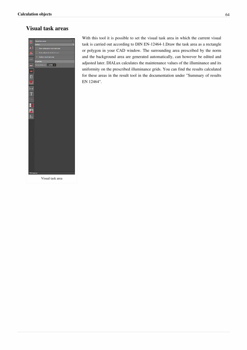
Calculation objects 64
Visual task areas
Visual task area
With this tool it is possible to set the visual task area in which the current visualtask is carried out according to DIN EN-12464-1.Draw the task area as a rectangleor polygon in your CAD window. The surrounding area prescribed by the normand the background area are generated automatically, can however be edited andadjusted later. DIALux calculates the maintenance values of the illuminance and itsuniformity on the prescribed illuminance grids. You can find the results calculatedfor these areas in the result tool in the documentation under "Summary of resultsEN 12464".
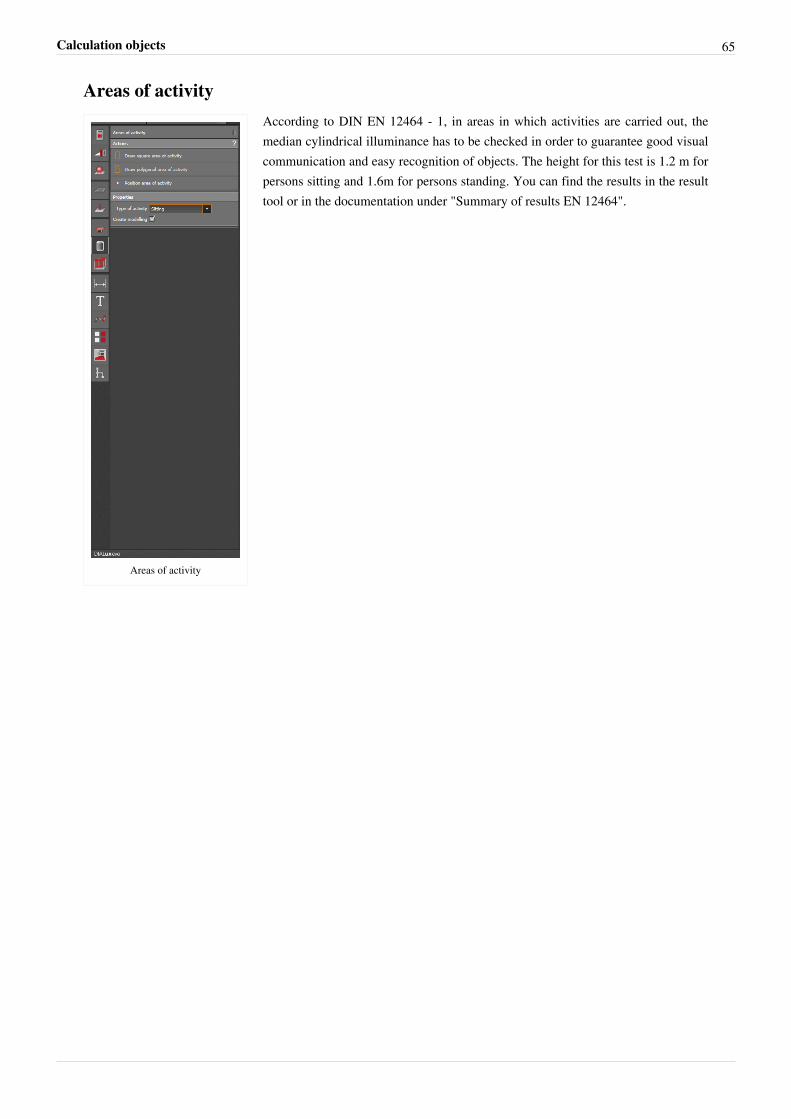
Calculation objects 65
Areas of activity
Areas of activity
According to DIN EN 12464 - 1, in areas in which activities are carried out, themedian cylindrical illuminance has to be checked in order to guarantee good visualcommunication and easy recognition of objects. The height for this test is 1.2 m forpersons sitting and 1.6m for persons standing. You can find the results in the resulttool or in the documentation under "Summary of results EN 12464".
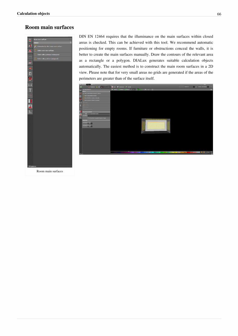
Calculation objects 66
Room main surfaces
Room main surfaces
DIN EN 12464 requires that the illuminance on the main surfaces within closedareas is checked. This can be achieved with this tool. We recommend automaticpositioning for empty rooms. If furniture or obstructions conceal the walls, it isbetter to create the main surfaces manually. Draw the contours of the relevant areaas a rectangle or a polygon. DIALux generates suitable calculation objectsautomatically. The easiest method is to construct the main room surfaces in a 2Dview. Please note that for very small areas no grids are generated if the areas of theperimeters are greater than of the surface itself.
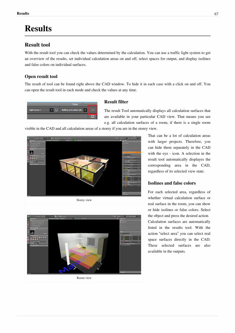
Results 67
Results
Result toolWith the result tool you can check the values determined by the calculation. You can use a traffic light system to getan overview of the results, set individual calculation areas on and off, select spaces for output, and display isolinesand false colors on individual surfaces.
Open result toolThe result of tool can be found right above the CAD window. To hide it in each case with a click on and off. Youcan open the result tool in each mode and check the values at any time.
Result filter
The result Tool automatically displays all calculation surfaces thatare available in your particular CAD view. That means you seee.g. all calculation surfaces of a room, if there is a single room
visible in the CAD and all calculation areas of a storey if you are in the storey view.
Storey view
Room view
That can be a lot of calculation areaswith larger projects. Therefore, youcan hide them separately in the CADwith the eye - icon. A selection in theresult tool automatically displayes thecorresponding area in the CAD,regardless of its selected view state.
Isolines and false colors
For each selected area, regardless ofwhether virtual calculation surface orreal surface in the room, you can showor hide isolines or false colors. Selectthe object and press the desired action.Calculation surfaces are automaticallylisted in the results tool. With theaction “select area” you can select realspace surfaces directly in the CAD.These selected surfaces are alsoavailable in the outputs.
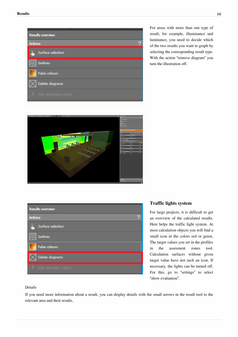
Results 68
For areas with more than one type ofresult, for example, illuminance andluminance, you need to decide whichof the two results you want to graph byselecting the corresponding result type.With the action “remove diagram” youturn the illustration off.
Traffic lights system
For large projects, it is difficult to getan overview of the calculated results.Here helps the traffic light system. Atmost calculation objects you will find asmall icon in the colors red or green.The target values you set in the profilesin the assesment zones tool.Calculation surfaces without giventarget value have not such an icon. Ifnecessary, the lights can be turned off.For this, go to “settings” to select“show evaluation”.
DetailsIf you need more information about a result, you can display details with the small arrows in the result tool to therelevant area and their results.
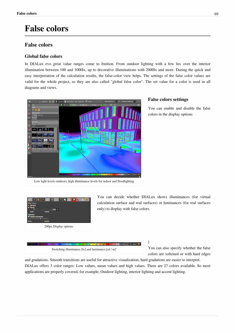
False colors 69
False colors
False colors
Global false colorsIn DIALux evo great value ranges come to fruition. From outdoor lighting with a few lux over the interiorillumination between 100 and 1000lx, up to decorative illuminations with 2000lx and more. During the quick andeasy interpretation of the calculation results, the false-color view helps. The settings of the false color values arevalid for the whole project, so they are also called "global false color". The set value for a color is used in alldiagrams and views.
Low light levels outdoors, high illuminance levels for indoor and floodlighting
False colors settings
You can enable and disable the falsecolors in the display options
200px Display options
You can decide whether DIALux shows illuminances (for virtualcalculation surface and real surfaces) or luminances (for real surfacesonly) to display with false colors.
Switching illuminance [lx] and luminance [cd / m2
]You can also specify whether the falsecolors are softened or with hard edges
and gradations. Smooth transitions are useful for attractive visualization, hard gradations are easier to interpret.DIALux offers 3 color ranges: Low values, mean values and high values. There are 27 colors available. So mostapplications are properly covered, for example, Outdoor lighting, interior lighting and accent lighting.
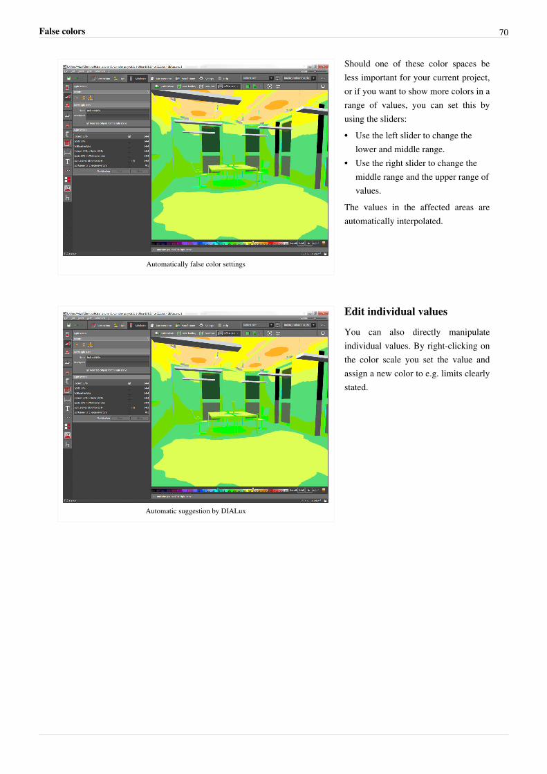
False colors 70
Automatically false color settings
Should one of these color spaces beless important for your current project,or if you want to show more colors in arange of values, you can set this byusing the sliders:•• Use the left slider to change the
lower and middle range.•• Use the right slider to change the
middle range and the upper range ofvalues.
The values in the affected areas areautomatically interpolated.
Automatic suggestion by DIALux
Edit individual values
You can also directly manipulateindividual values. By right-clicking onthe color scale you set the value andassign a new color to e.g. limits clearlystated.
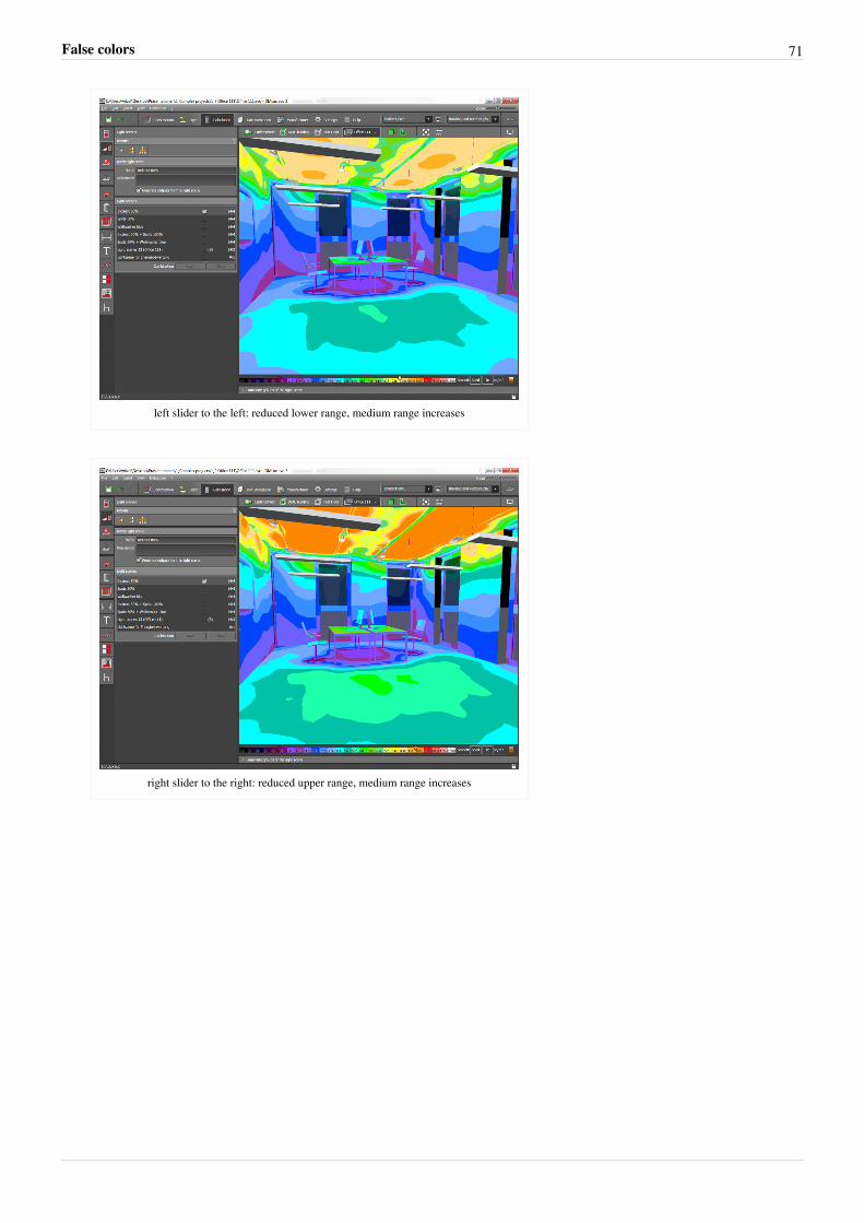
False colors 71
left slider to the left: reduced lower range, medium range increases
right slider to the right: reduced upper range, medium range increases
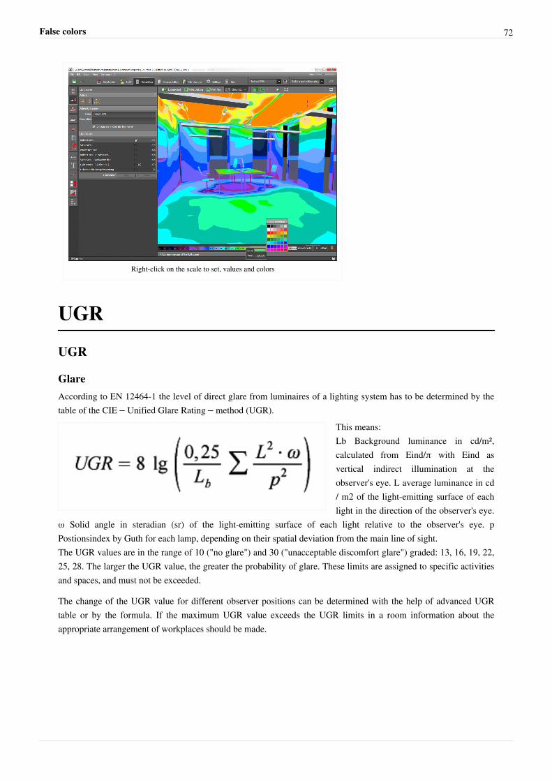
False colors 72
Right-click on the scale to set, values and colors
UGR
UGR
GlareAccording to EN 12464-1 the level of direct glare from luminaires of a lighting system has to be determined by thetable of the CIE – Unified Glare Rating – method (UGR).
This means:Lb Background luminance in cd/m²,calculated from Eind/π with Eind asvertical indirect illumination at theobserver's eye. L average luminance in cd/ m2 of the light-emitting surface of eachlight in the direction of the observer's eye.
ω Solid angle in steradian (sr) of the light-emitting surface of each light relative to the observer's eye. pPostionsindex by Guth for each lamp, depending on their spatial deviation from the main line of sight.The UGR values are in the range of 10 ("no glare") and 30 ("unacceptable discomfort glare") graded: 13, 16, 19, 22,25, 28. The larger the UGR value, the greater the probability of glare. These limits are assigned to specific activitiesand spaces, and must not be exceeded.
The change of the UGR value for different observer positions can be determined with the help of advanced UGRtable or by the formula. If the maximum UGR value exceeds the UGR limits in a room information about theappropriate arrangement of workplaces should be made.
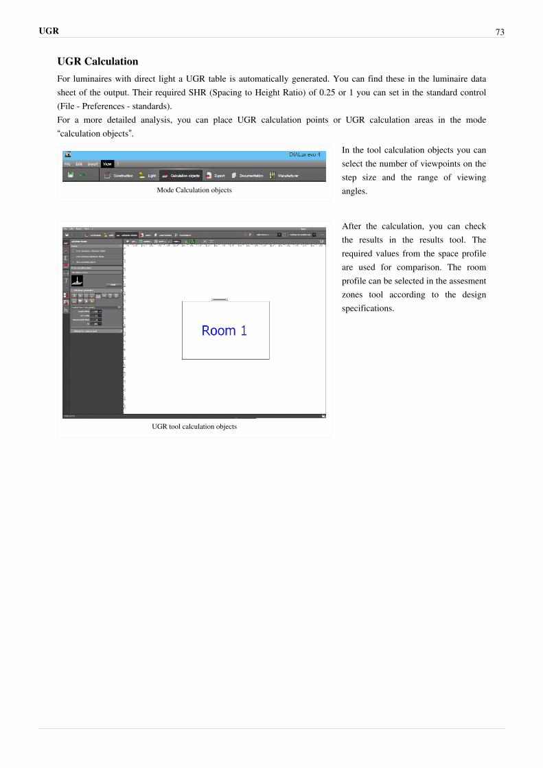
UGR 73
UGR CalculationFor luminaires with direct light a UGR table is automatically generated. You can find these in the luminaire datasheet of the output. Their required SHR (Spacing to Height Ratio) of 0.25 or 1 you can set in the standard control(File - Preferences - standards).For a more detailed analysis, you can place UGR calculation points or UGR calculation areas in the mode“calculation objects”.
Mode Calculation objects
In the tool calculation objects you canselect the number of viewpoints on thestep size and the range of viewingangles.
UGR tool calculation objects
After the calculation, you can checkthe results in the results tool. Therequired values from the space profileare used for comparison. The roomprofile can be selected in the assesmentzones tool according to the designspecifications.
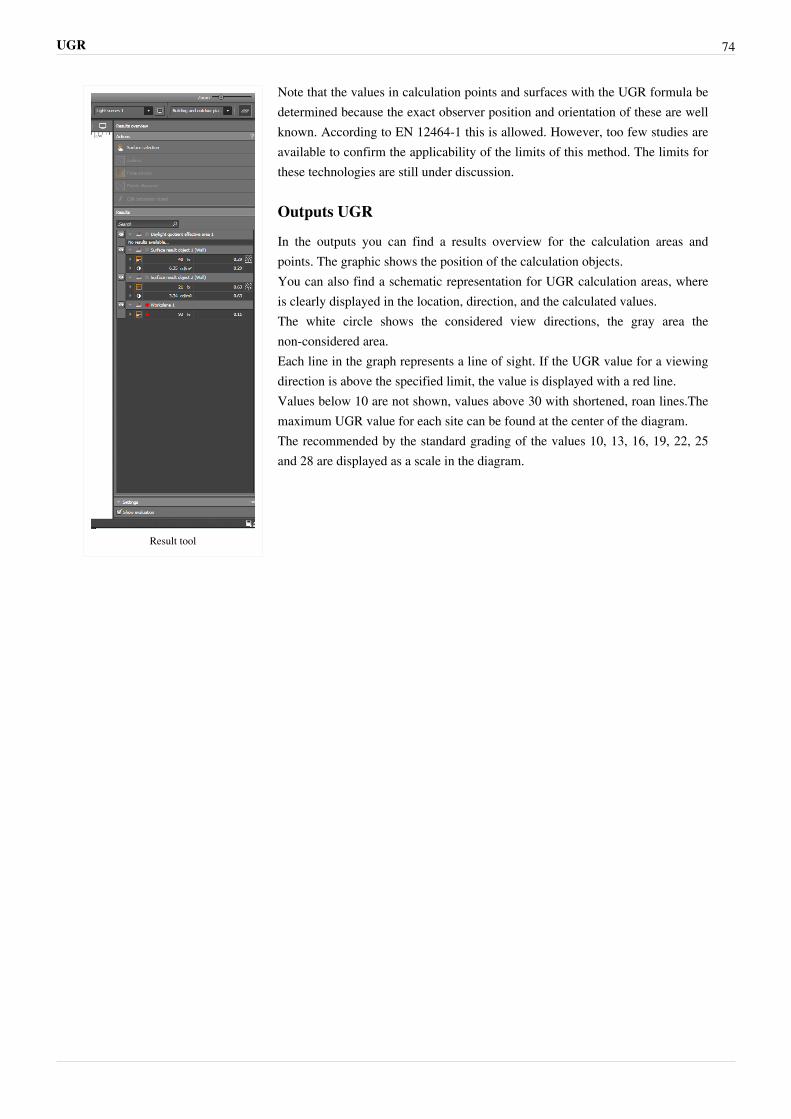
UGR 74
Result tool
Note that the values in calculation points and surfaces with the UGR formula bedetermined because the exact observer position and orientation of these are wellknown. According to EN 12464-1 this is allowed. However, too few studies areavailable to confirm the applicability of the limits of this method. The limits forthese technologies are still under discussion.
Outputs UGR
In the outputs you can find a results overview for the calculation areas andpoints. The graphic shows the position of the calculation objects.You can also find a schematic representation for UGR calculation areas, whereis clearly displayed in the location, direction, and the calculated values.The white circle shows the considered view directions, the gray area thenon-considered area.Each line in the graph represents a line of sight. If the UGR value for a viewingdirection is above the specified limit, the value is displayed with a red line.Values below 10 are not shown, values above 30 with shortened, roan lines.Themaximum UGR value for each site can be found at the center of the diagram.The recommended by the standard grading of the values 10, 13, 16, 19, 22, 25and 28 are displayed as a scale in the diagram.
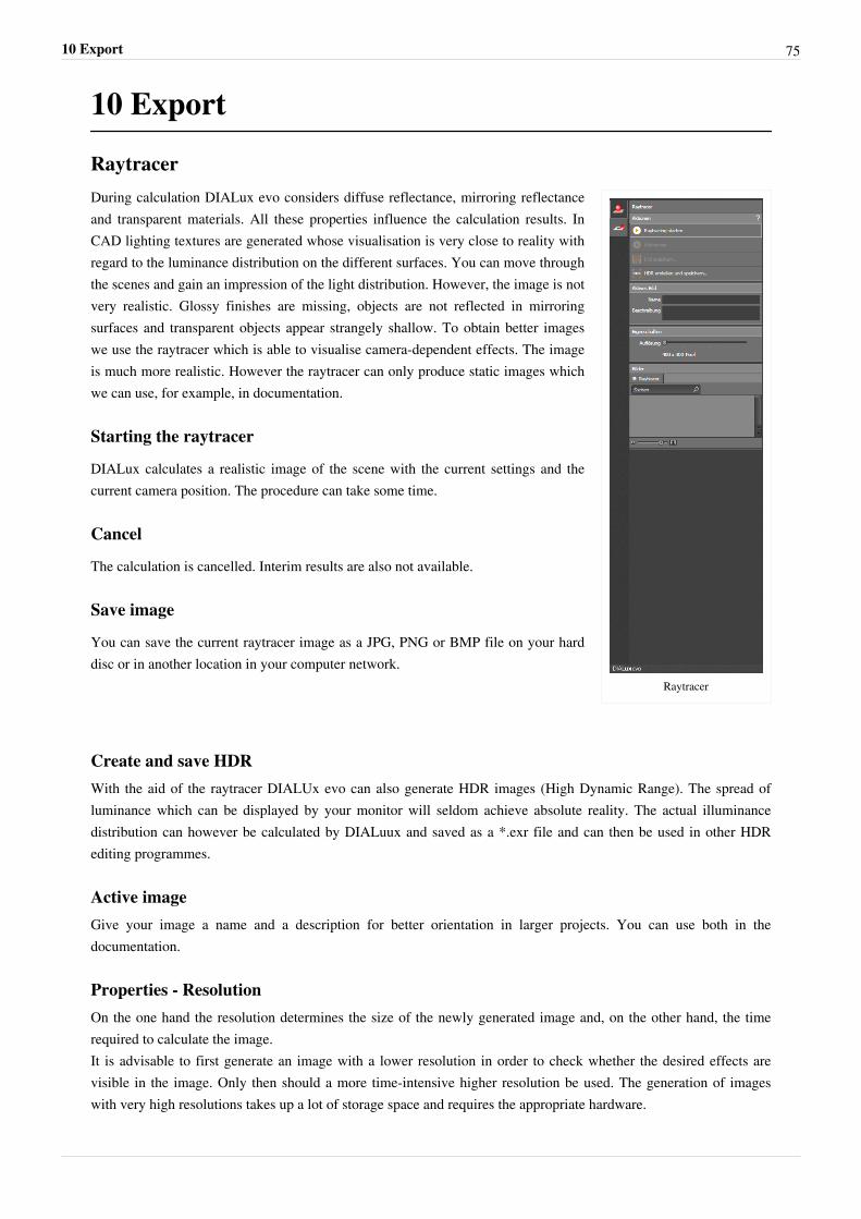
10 Export 75
10 Export
Raytracer
Raytracer
During calculation DIALux evo considers diffuse reflectance, mirroring reflectanceand transparent materials. All these properties influence the calculation results. InCAD lighting textures are generated whose visualisation is very close to reality withregard to the luminance distribution on the different surfaces. You can move throughthe scenes and gain an impression of the light distribution. However, the image is notvery realistic. Glossy finishes are missing, objects are not reflected in mirroringsurfaces and transparent objects appear strangely shallow. To obtain better imageswe use the raytracer which is able to visualise camera-dependent effects. The imageis much more realistic. However the raytracer can only produce static images whichwe can use, for example, in documentation.
Starting the raytracer
DIALux calculates a realistic image of the scene with the current settings and thecurrent camera position. The procedure can take some time.
Cancel
The calculation is cancelled. Interim results are also not available.
Save image
You can save the current raytracer image as a JPG, PNG or BMP file on your harddisc or in another location in your computer network.
Create and save HDRWith the aid of the raytracer DIALUx evo can also generate HDR images (High Dynamic Range). The spread ofluminance which can be displayed by your monitor will seldom achieve absolute reality. The actual illuminancedistribution can however be calculated by DIALuux and saved as a *.exr file and can then be used in other HDRediting programmes.
Active imageGive your image a name and a description for better orientation in larger projects. You can use both in thedocumentation.
Properties - ResolutionOn the one hand the resolution determines the size of the newly generated image and, on the other hand, the timerequired to calculate the image.It is advisable to first generate an image with a lower resolution in order to check whether the desired effects arevisible in the image. Only then should a more time-intensive higher resolution be used. The generation of imageswith very high resolutions takes up a lot of storage space and requires the appropriate hardware.
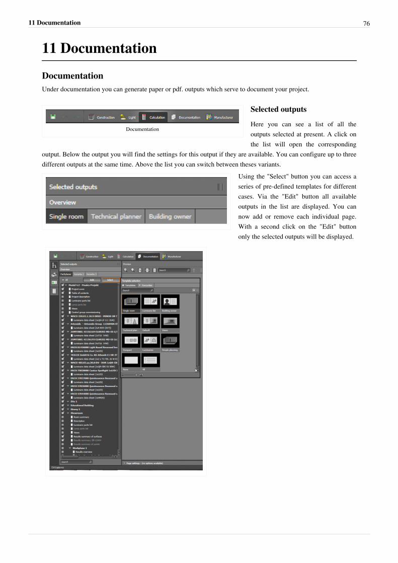
11 Documentation 76
11 Documentation
DocumentationUnder documentation you can generate paper or pdf. outputs which serve to document your project.
Documentation
Selected outputs
Here you can see a list of all theoutputs selected at present. A click onthe list will open the corresponding
output. Below the output you will find the settings for this output if they are available. You can configure up to threedifferent outputs at the same time. Above the list you can switch between theses variants.
Using the "Select" button you can access aseries of pre-defined templates for differentcases. Via the "Edit" button all availableoutputs in the list are displayed. You cannow add or remove each individual page.With a second click on the "Edit" buttononly the selected outputs will be displayed.
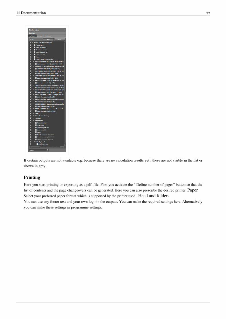
11 Documentation 77
If certain outputs are not available e.g. because there are no calculation results yet , these are not visible in the list orshown in grey.
PrintingHere you start printing or exporting as a pdf. file. First you activate the " Define number of pages" button so that thelist of contents and the page changeovers can be generated. Here you can also prescribe the desired printer. PaperSelect your preferred paper format which is supported by the printer used . Head and foldersYou can use any footer text and your own logo in the outputs. You can make the required settings here. Alternativelyyou can make these settings in programme settings.
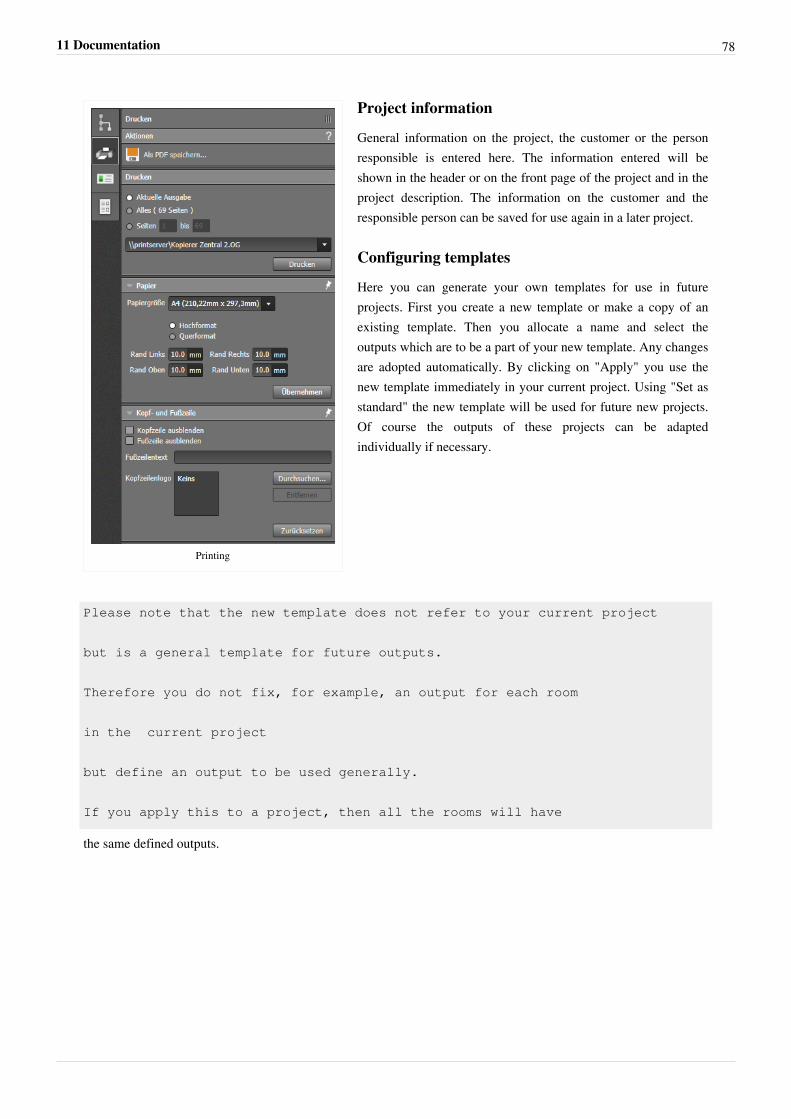
11 Documentation 78
Printing
Project information
General information on the project, the customer or the personresponsible is entered here. The information entered will beshown in the header or on the front page of the project and in theproject description. The information on the customer and theresponsible person can be saved for use again in a later project.
Configuring templates
Here you can generate your own templates for use in futureprojects. First you create a new template or make a copy of anexisting template. Then you allocate a name and select theoutputs which are to be a part of your new template. Any changesare adopted automatically. By clicking on "Apply" you use thenew template immediately in your current project. Using "Set asstandard" the new template will be used for future new projects.Of course the outputs of these projects can be adaptedindividually if necessary.
Please note that the new template does not refer to your current project
but is a general template for future outputs.
Therefore you do not fix, for example, an output for each room
in the current project
but define an output to be used generally.
If you apply this to a project, then all the rooms will have
the same defined outputs.
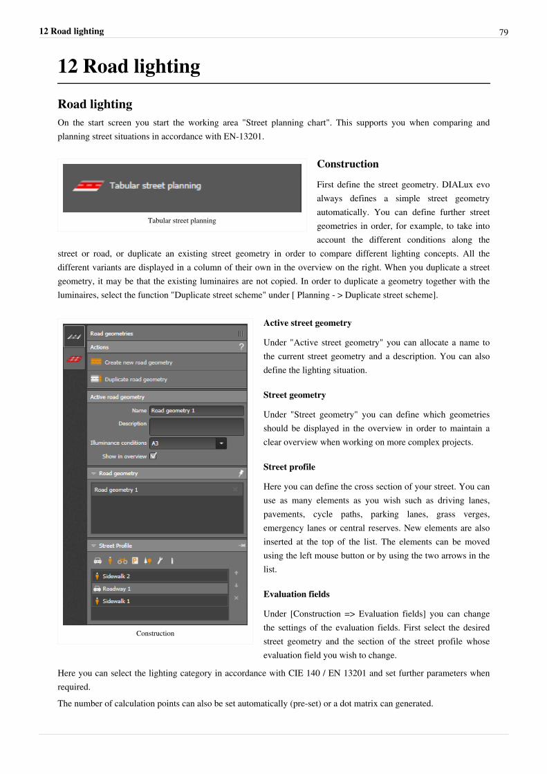
12 Road lighting 79
12 Road lighting
Road lightingOn the start screen you start the working area "Street planning chart". This supports you when comparing andplanning street situations in accordance with EN-13201.
Tabular street planning
Construction
First define the street geometry. DIALux evoalways defines a simple street geometryautomatically. You can define further streetgeometries in order, for example, to take intoaccount the different conditions along the
street or road, or duplicate an existing street geometry in order to compare different lighting concepts. All thedifferent variants are displayed in a column of their own in the overview on the right. When you duplicate a streetgeometry, it may be that the existing luminaires are not copied. In order to duplicate a geometry together with theluminaires, select the function "Duplicate street scheme" under [ Planning - > Duplicate street scheme].
Construction
Active street geometry
Under "Active street geometry" you can allocate a name tothe current street geometry and a description. You can alsodefine the lighting situation.
Street geometry
Under "Street geometry" you can define which geometriesshould be displayed in the overview in order to maintain aclear overview when working on more complex projects.
Street profile
Here you can define the cross section of your street. You canuse as many elements as you wish such as driving lanes,pavements, cycle paths, parking lanes, grass verges,emergency lanes or central reserves. New elements are alsoinserted at the top of the list. The elements can be movedusing the left mouse button or by using the two arrows in thelist.
Evaluation fields
Under [Construction => Evaluation fields] you can changethe settings of the evaluation fields. First select the desiredstreet geometry and the section of the street profile whoseevaluation field you wish to change.
Here you can select the lighting category in accordance with CIE 140 / EN 13201 and set further parameters whenrequired.The number of calculation points can also be set automatically (pre-set) or a dot matrix can generated.
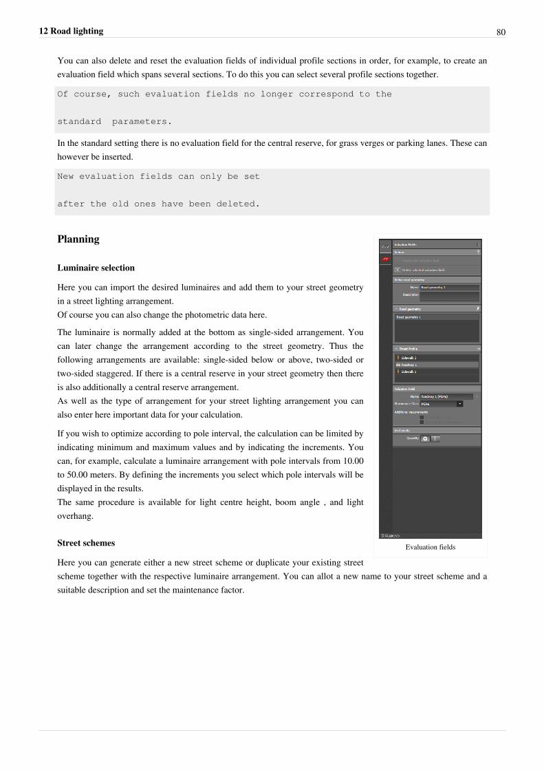
12 Road lighting 80
You can also delete and reset the evaluation fields of individual profile sections in order, for example, to create anevaluation field which spans several sections. To do this you can select several profile sections together.
Of course, such evaluation fields no longer correspond to the
standard parameters.
In the standard setting there is no evaluation field for the central reserve, for grass verges or parking lanes. These canhowever be inserted.
New evaluation fields can only be set
after the old ones have been deleted.
Evaluation fields
Planning
Luminaire selection
Here you can import the desired luminaires and add them to your street geometryin a street lighting arrangement.Of course you can also change the photometric data here.
The luminaire is normally added at the bottom as single-sided arrangement. Youcan later change the arrangement according to the street geometry. Thus thefollowing arrangements are available: single-sided below or above, two-sided ortwo-sided staggered. If there is a central reserve in your street geometry then thereis also additionally a central reserve arrangement.As well as the type of arrangement for your street lighting arrangement you canalso enter here important data for your calculation.
If you wish to optimize according to pole interval, the calculation can be limited byindicating minimum and maximum values and by indicating the increments. Youcan, for example, calculate a luminaire arrangement with pole intervals from 10.00to 50.00 meters. By defining the increments you select which pole intervals will bedisplayed in the results.The same procedure is available for light centre height, boom angle , and lightoverhang.
Street schemes
Here you can generate either a new street scheme or duplicate your existing streetscheme together with the respective luminaire arrangement. You can allot a new name to your street scheme and asuitable description and set the maintenance factor.
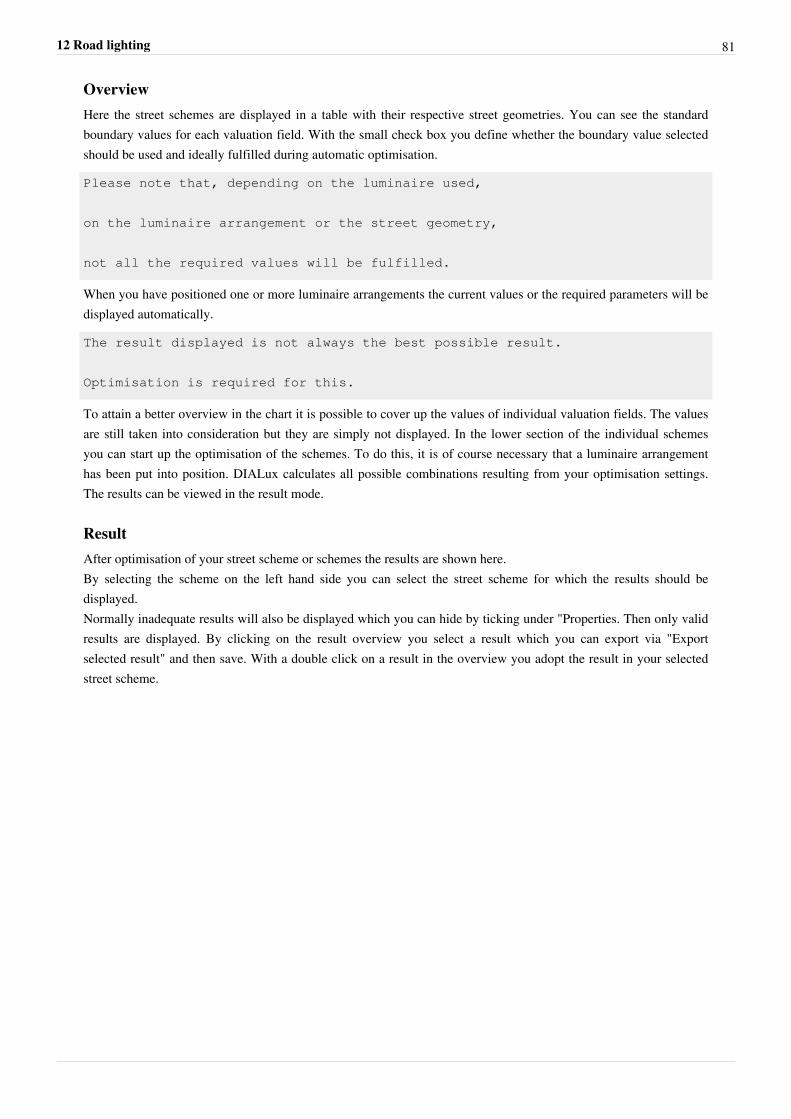
12 Road lighting 81
OverviewHere the street schemes are displayed in a table with their respective street geometries. You can see the standardboundary values for each valuation field. With the small check box you define whether the boundary value selectedshould be used and ideally fulfilled during automatic optimisation.
Please note that, depending on the luminaire used,
on the luminaire arrangement or the street geometry,
not all the required values will be fulfilled.
When you have positioned one or more luminaire arrangements the current values or the required parameters will bedisplayed automatically.
The result displayed is not always the best possible result.
Optimisation is required for this.
To attain a better overview in the chart it is possible to cover up the values of individual valuation fields. The valuesare still taken into consideration but they are simply not displayed. In the lower section of the individual schemesyou can start up the optimisation of the schemes. To do this, it is of course necessary that a luminaire arrangementhas been put into position. DIALux calculates all possible combinations resulting from your optimisation settings.The results can be viewed in the result mode.
ResultAfter optimisation of your street scheme or schemes the results are shown here.By selecting the scheme on the left hand side you can select the street scheme for which the results should bedisplayed.Normally inadequate results will also be displayed which you can hide by ticking under "Properties. Then only validresults are displayed. By clicking on the result overview you select a result which you can export via "Exportselected result" and then save. With a double click on a result in the overview you adopt the result in your selectedstreet scheme.
13 Tutorials 82
13 TutorialsDIALux YouTube Tutorial-Channel "The DIALux" [1]
Here you have the opportunity to watch fascinating DIALux tutorials. We offer a wide range of different videos witha variety of content. With theses videos we wish to make it easier for our users when first working with DIALux andat the same time to explain what possibilities the software offers.#1 beginner´s guide [2]
#2 CAD import [3]
#3 building construction [4]
#4 doors and windows [5]
#5 inserting luminaires [6]
#6 arranging lights [7]
#7 raytracer [8]
#8 Output function [9]
#9 View Options [10]
#10 Street lighting [11]
#11 Daylight calculation [12]
#12 Simple indoor planing [13]
#13 DIALux evo tutorial— Staircases part 1: Handling of extrusion objects [14]
#14 DIALux evo tutorial- Staircases part 2: Copy along a line [15]
#15 DIALux evo tutorial— White balance, camera positions, ... [16]
#16 DIALux evo tutorial Creating and calculating roundabouts [17]
#17 DIALux evo tutorial - UGR-Calculation [18]
# 18 DIALux evo tutorial - Drawing from scratch [19]
# 19 DIALux evo tutorial - Road and street lighting: Calculation of the median strip [20]
# 20 DIALux evo tutorial - Maintenance factors and improvements [21]
References[1] http:/ / www. youtube. com/ user/ TheDIALux?feature=watch[2] http:/ / www. youtube. com/ watch?v=Hy6AemgOlKY& feature=c4-overview& list=UUxLhvUzOGs8y14NSEQOTVDg[3] http:/ / www. youtube. com/ watch?v=fo-oxio7j6Y& feature=c4-overview& list=UUxLhvUzOGs8y14NSEQOTVDg[4] http:/ / www. youtube. com/ watch?v=incIAPjQKMI& feature=c4-overview& list=UUxLhvUzOGs8y14NSEQOTVDg[5] http:/ / www. youtube. com/ watch?v=38C_gqe15dU& feature=c4-overview& list=UUxLhvUzOGs8y14NSEQOTVDg[6] http:/ / www. youtube. com/ watch?v=6JSwpmtJ7A4& list=UUxLhvUzOGs8y14NSEQOTVDg[7] http:/ / www. youtube. com/ watch?v=QRSAuBI0TTw& list=UUxLhvUzOGs8y14NSEQOTVDg[8] http:/ / www. youtube. com/ watch?v=hcEYIz1jeXM& list=UUxLhvUzOGs8y14NSEQOTVDg[9] https:/ / www. youtube. com/ watch?v=RsCk8ZE2-WY[10] https:/ / www. youtube. com/ watch?v=_GLGnSDGna4& feature=youtu. be[11] http:/ / www. youtube. com/ watch?v=GGrcmt4irbc& list=UUxLhvUzOGs8y14NSEQOTVDg[12] https:/ / www. youtube. com/ watch?v=7DIaS0GA8j4[13] https:/ / www. youtube. com/ watch?v=8bcuUx8S7AI[14] https:/ / www. youtube. com/ watch?v=IQoMXyRcuU0[15] https:/ / www. youtube. com/ watch?v=u4SiBtTtJb0[16] https:/ / www. youtube. com/ watch?v=hhZiNKH_IYw[17] https:/ / www. youtube. com/ watch?v=qoMGDNVrOAM[18] https:/ / www. youtube. com/ watch?v=mdsigGGrNUM
13 Tutorials 83
[19] https:/ / www. youtube. com/ watch?v=jCh5AwuPe3w[20] https:/ / www. youtube. com/ watch?v=I8wOvN6-5kQ[21] https:/ / www. youtube. com/ watch?v=dkcRmU2VFck
14 Standards
StandardsThe following standards are used in Dialux evo:EN12464-I, 20011-08 Indoor work places•• Areas•• Applications•• Glare indoors (UGR)•• Maintenance value of illuminance in the task area•• Maintenance value of illuminance in the surrounding area•• Maintenance value of the lighting for the background area•• color rendering index•• Illumination uniformityEN 12464-2, 2014-05 Outdoor work places•• Areas•• Applications•• Glare outdoors (GR)•• Maintenance value of illuminance in the task area•• Maintenance value of illuminance in the surrounding area•• Maintenance value of the lighting for the background area•• color rendering index•• Illumination uniformityDIN V 18599 Energetic rating of buildings part 10, 2011•• Height of the workplane•• Space index (k)•• Use times at day•• Use times at night•• Partial operation factor•• Reduction factorCIE 097-2005 2nd Edition, Guide to the maintenance of electric lighting equipment•• Ambient conditions•• Maintenance interval•• Maintenance interval for luminaires•• Replacement interval of lamps•• Illuminance ratio after LG7•• Consideration of a reflection on the ceiling under emergency lighting for LG12•• Ratio distance to height, SHR•• Maintenance value according to EN 12 464 or overallRovl 2011
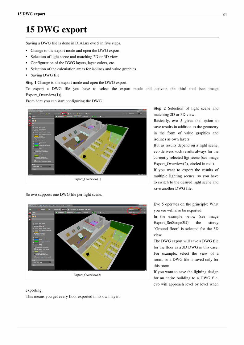
15 DWG export 84
15 DWG exportSaving a DWG file is done in DIALux evo 5 in five steps.•• Change to the export mode and open the DWG export•• Selection of light scene and matching 2D or 3D view•• Configuration of the DWG layers, layer colors, etc.•• Selection of the calculation areas for isolines and value graphics.•• Saving DWG fileStep 1 Change to the export mode and open the DWG export:To export a DWG file you have to select the export mode and activate the third tool (see imageExport_Overview(1)).From here you can start configuring the DWG.
Export_Overview(1)
Step 2 Selection of light scene andmatching 2D or 3D view:Basically, evo 5 gives the option tosave results in addition to the geometryin the form of value graphics andisolines as own layers.But as results depend on a light scene,evo delivers such results always for thecurrently selected ligt scene (see imageExport_Overview(2), circled in red ).If you want to export the results ofmultiple lighting scenes, so you haveto switch to the desired light scene andsave another DWG file.
So evo supports one DWG file per light scene.
Export_Overview(2)
Evo 5 operates on the principle: Whatyou see will also be exported.In the example below (see imageExport_SetScope3D) the storey"Ground floor" is selected for the 3Dview.The DWG export will save a DWG filefor the floor as a 3D DWG in this case.For example, select the view of aroom, so a DWG file is saved only forthis room.If you want to save the lighting designfor an entire building to a DWG file,evo will approach level by level when
exporting.This means you get every floor exported in its own layer.
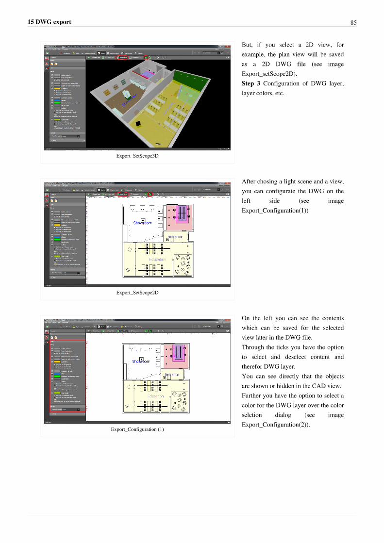
15 DWG export 85
Export_SetScope3D
But, if you select a 2D view, forexample, the plan view will be savedas a 2D DWG file (see imageExport_setScope2D).Step 3 Configuration of DWG layer,layer colors, etc.
Export_SetScope2D
After chosing a light scene and a view,you can configurate the DWG on theleft side (see imageExport_Configuration(1))
Export_Configuration (1)
On the left you can see the contentswhich can be saved for the selectedview later in the DWG file.Through the ticks you have the optionto select and deselect content andtherefor DWG layer.You can see directly that the objectsare shown or hidden in the CAD view.Further you have the option to select acolor for the DWG layer over the colorselction dialog (see imageExport_Configuration(2)).
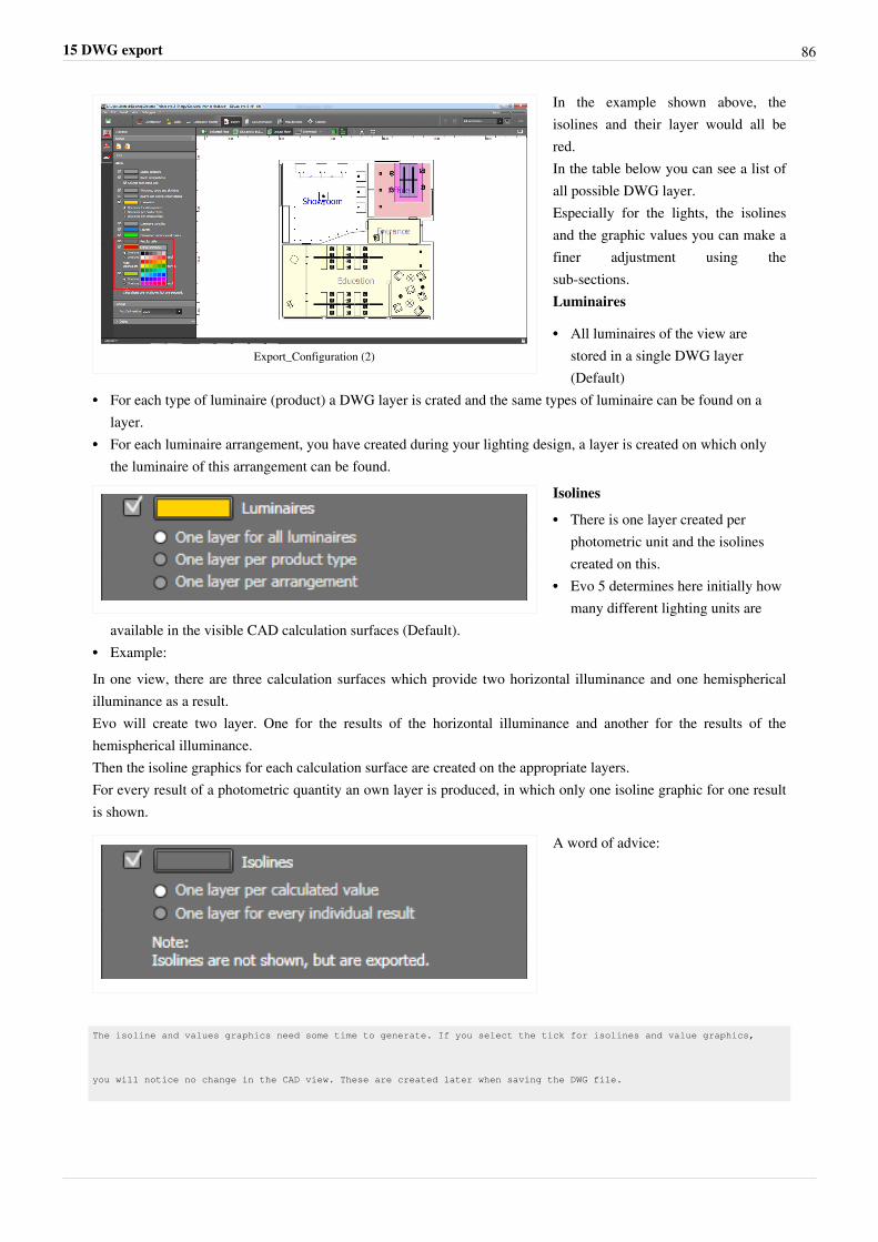
15 DWG export 86
Export_Configuration (2)
In the example shown above, theisolines and their layer would all bered.In the table below you can see a list ofall possible DWG layer.Especially for the lights, the isolinesand the graphic values you can make afiner adjustment using thesub-sections.Luminaires
•• All luminaires of the view arestored in a single DWG layer(Default)
•• For each type of luminaire (product) a DWG layer is crated and the same types of luminaire can be found on alayer.
•• For each luminaire arrangement, you have created during your lighting design, a layer is created on which onlythe luminaire of this arrangement can be found.
Isolines
•• There is one layer created perphotometric unit and the isolinescreated on this.
•• Evo 5 determines here initially howmany different lighting units are
available in the visible CAD calculation surfaces (Default).•• Example:In one view, there are three calculation surfaces which provide two horizontal illuminance and one hemisphericalilluminance as a result.Evo will create two layer. One for the results of the horizontal illuminance and another for the results of thehemispherical illuminance.Then the isoline graphics for each calculation surface are created on the appropriate layers.For every result of a photometric quantity an own layer is produced, in which only one isoline graphic for one resultis shown.
A word of advice:
The isoline and values graphics need some time to generate. If you select the tick for isolines and value graphics,
you will notice no change in the CAD view. These are created later when saving the DWG file.
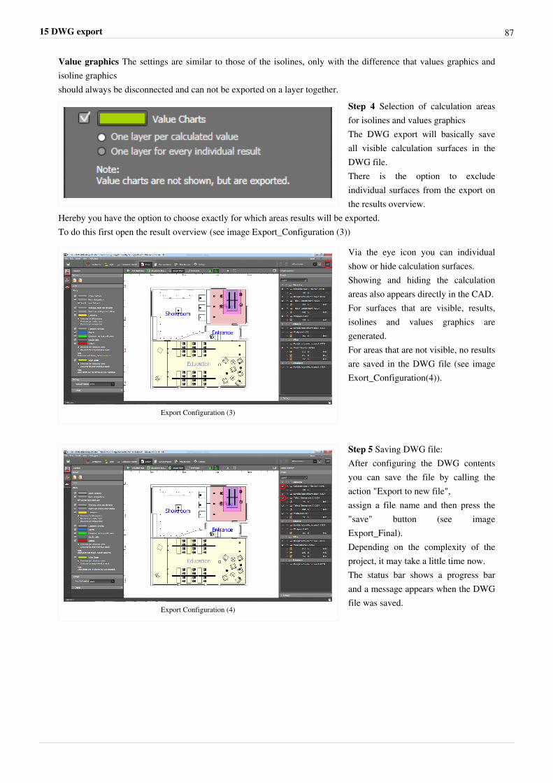
15 DWG export 87
Value graphics The settings are similar to those of the isolines, only with the difference that values graphics andisoline graphicsshould always be disconnected and can not be exported on a layer together.
Step 4 Selection of calculation areasfor isolines and values graphicsThe DWG export will basically saveall visible calculation surfaces in theDWG file.There is the option to excludeindividual surfaces from the export onthe results overview.
Hereby you have the option to choose exactly for which areas results will be exported.To do this first open the result overview (see image Export_Configuration (3))
Export Configuration (3)
Via the eye icon you can individualshow or hide calculation surfaces.Showing and hiding the calculationareas also appears directly in the CAD.For surfaces that are visible, results,isolines and values graphics aregenerated.For areas that are not visible, no resultsare saved in the DWG file (see imageExort_Configuration(4)).
Export Configuration (4)
Step 5 Saving DWG file:After configuring the DWG contentsyou can save the file by calling theaction "Export to new file",assign a file name and then press the"save" button (see imageExport_Final).Depending on the complexity of theproject, it may take a little time now.The status bar shows a progress barand a message appears when the DWGfile was saved.
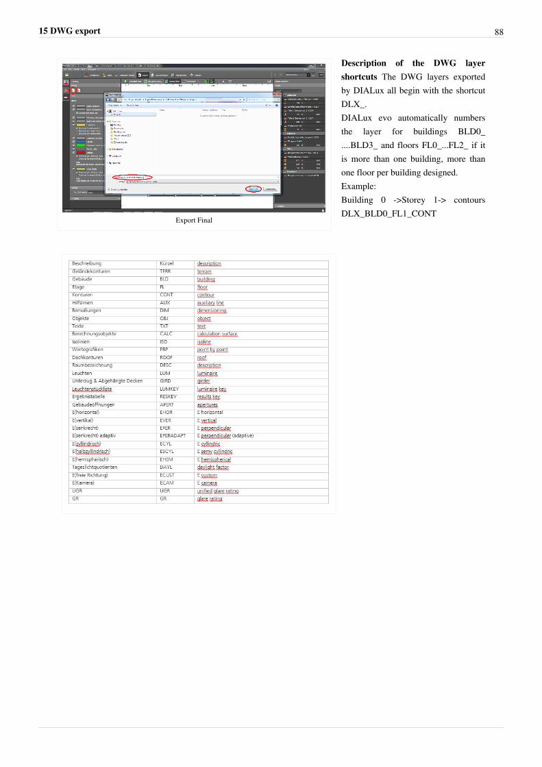
15 DWG export 88
Export Final
Description of the DWG layershortcuts The DWG layers exportedby DIALux all begin with the shortcutDLX_.DIALux evo automatically numbersthe layer for buildings BLD0_....BLD3_ and floors FL0_...FL2_ if itis more than one building, more thanone floor per building designed.Example:Building 0 ->Storey 1-> contoursDLX_BLD0_FL1_CONT
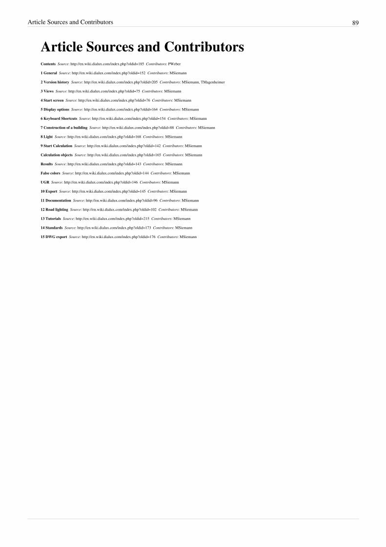
Article Sources and Contributors 89
Article Sources and ContributorsContents Source: http://en.wiki.dialux.com/index.php?oldid=185 Contributors: PWeber
1 General Source: http://en.wiki.dialux.com/index.php?oldid=152 Contributors: MSiemann
2 Version history Source: http://en.wiki.dialux.com/index.php?oldid=205 Contributors: MSiemann, TMagenheimer
3 Views Source: http://en.wiki.dialux.com/index.php?oldid=75 Contributors: MSiemann
4 Start screen Source: http://en.wiki.dialux.com/index.php?oldid=76 Contributors: MSiemann
5 Display options Source: http://en.wiki.dialux.com/index.php?oldid=164 Contributors: MSiemann
6 Keyboard Shortcuts Source: http://en.wiki.dialux.com/index.php?oldid=154 Contributors: MSiemann
7 Construction of a building Source: http://en.wiki.dialux.com/index.php?oldid=88 Contributors: MSiemann
8 Light Source: http://en.wiki.dialux.com/index.php?oldid=168 Contributors: MSiemann
9 Start Calculation Source: http://en.wiki.dialux.com/index.php?oldid=142 Contributors: MSiemann
Calculation objects Source: http://en.wiki.dialux.com/index.php?oldid=165 Contributors: MSiemann
Results Source: http://en.wiki.dialux.com/index.php?oldid=143 Contributors: MSiemann
False colors Source: http://en.wiki.dialux.com/index.php?oldid=144 Contributors: MSiemann
UGR Source: http://en.wiki.dialux.com/index.php?oldid=146 Contributors: MSiemann
10 Export Source: http://en.wiki.dialux.com/index.php?oldid=145 Contributors: MSiemann
11 Documentation Source: http://en.wiki.dialux.com/index.php?oldid=96 Contributors: MSiemann
12 Road lighting Source: http://en.wiki.dialux.com/index.php?oldid=102 Contributors: MSiemann
13 Tutorials Source: http://en.wiki.dialux.com/index.php?oldid=215 Contributors: MSiemann
14 Standards Source: http://en.wiki.dialux.com/index.php?oldid=173 Contributors: MSiemann
15 DWG export Source: http://en.wiki.dialux.com/index.php?oldid=176 Contributors: MSiemann
Image Sources, Licenses and Contributors 90
Image Sources, Licenses and ContributorsFile:DIALux 4.png Source: http://en.wiki.dialux.com/index.php?title=File:DIALux_4.png License: unknown Contributors: DWitzelFile:DIALux evo.png Source: http://en.wiki.dialux.com/index.php?title=File:DIALux_evo.png License: unknown Contributors: DWitzelFile:General_settings.PNG Source: http://en.wiki.dialux.com/index.php?title=File:General_settings.PNG License: unknown Contributors: MSiemannFile:General.PNG Source: http://en.wiki.dialux.com/index.php?title=File:General.PNG License: unknown Contributors: MSiemannFile:New.PNG Source: http://en.wiki.dialux.com/index.php?title=File:New.PNG License: unknown Contributors: MSiemannFile:Modi01.PNG Source: http://en.wiki.dialux.com/index.php?title=File:Modi01.PNG License: unknown Contributors: MSiemannFile:Tools_and_options.PNG Source: http://en.wiki.dialux.com/index.php?title=File:Tools_and_options.PNG License: unknown Contributors: MSiemannFile:Calculation progress.PNG Source: http://en.wiki.dialux.com/index.php?title=File:Calculation_progress.PNG License: unknown Contributors: MSiemannFile:Calculation01.PNG Source: http://en.wiki.dialux.com/index.php?title=File:Calculation01.PNG License: unknown Contributors: MSiemannFile:Beispiel.png Source: http://en.wiki.dialux.com/index.php?title=File:Beispiel.png License: unknown Contributors: MSiemannFile:Falschfarben.png Source: http://en.wiki.dialux.com/index.php?title=File:Falschfarben.png License: unknown Contributors: MSiemannFile:UGR.png Source: http://en.wiki.dialux.com/index.php?title=File:UGR.png License: unknown Contributors: MSiemannFile:Lichtstärketabelle.png Source: http://en.wiki.dialux.com/index.php?title=File:Lichtstärketabelle.png License: unknown Contributors: MSiemannFile:Tageslicht.png Source: http://en.wiki.dialux.com/index.php?title=File:Tageslicht.png License: unknown Contributors: MSiemannFile:Falschfarben2.png Source: http://en.wiki.dialux.com/index.php?title=File:Falschfarben2.png License: unknown Contributors: MSiemannFile:Ergebnistool.png Source: http://en.wiki.dialux.com/index.php?title=File:Ergebnistool.png License: unknown Contributors: MSiemannFile:Views.PNG Source: http://en.wiki.dialux.com/index.php?title=File:Views.PNG License: unknown Contributors: MSiemannFile:Site.PNG Source: http://en.wiki.dialux.com/index.php?title=File:Site.PNG License: unknown Contributors: MSiemannFile:Building.PNG Source: http://en.wiki.dialux.com/index.php?title=File:Building.PNG License: unknown Contributors: MSiemannFile:Floor.PNG Source: http://en.wiki.dialux.com/index.php?title=File:Floor.PNG License: unknown Contributors: MSiemannFile:Room.PNG Source: http://en.wiki.dialux.com/index.php?title=File:Room.PNG License: unknown Contributors: MSiemannFile:Views01.PNG Source: http://en.wiki.dialux.com/index.php?title=File:Views01.PNG License: unknown Contributors: MSiemannFile:Views03.PNG Source: http://en.wiki.dialux.com/index.php?title=File:Views03.PNG License: unknown Contributors: MSiemannFile:3D-rendering.PNG Source: http://en.wiki.dialux.com/index.php?title=File:3D-rendering.PNG License: unknown Contributors: MSiemannFile:Room1.PNG Source: http://en.wiki.dialux.com/index.php?title=File:Room1.PNG License: unknown Contributors: MSiemannFile:Measure_tape.PNG Source: http://en.wiki.dialux.com/index.php?title=File:Measure_tape.PNG License: unknown Contributors: MSiemannFile:Feedback.PNG Source: http://en.wiki.dialux.com/index.php?title=File:Feedback.PNG License: unknown Contributors: MSiemannFile:Start.PNG Source: http://en.wiki.dialux.com/index.php?title=File:Start.PNG License: unknown Contributors: MSiemannFile:Dwgdxf_import.PNG Source: http://en.wiki.dialux.com/index.php?title=File:Dwgdxf_import.PNG License: unknown Contributors: MSiemannFile:Empty.PNG Source: http://en.wiki.dialux.com/index.php?title=File:Empty.PNG License: unknown Contributors: MSiemannFile:Street.PNG Source: http://en.wiki.dialux.com/index.php?title=File:Street.PNG License: unknown Contributors: MSiemannFile:Simple.PNG Source: http://en.wiki.dialux.com/index.php?title=File:Simple.PNG License: unknown Contributors: MSiemannFile:History.PNG Source: http://en.wiki.dialux.com/index.php?title=File:History.PNG License: unknown Contributors: MSiemannFile:Manufacterer.PNG Source: http://en.wiki.dialux.com/index.php?title=File:Manufacterer.PNG License: unknown Contributors: MSiemannFile:Support.PNG Source: http://en.wiki.dialux.com/index.php?title=File:Support.PNG License: unknown Contributors: MSiemannFile:Homepage.PNG Source: http://en.wiki.dialux.com/index.php?title=File:Homepage.PNG License: unknown Contributors: MSiemannFile:Settings.PNG Source: http://en.wiki.dialux.com/index.php?title=File:Settings.PNG License: unknown Contributors: MSiemannFile:Menu01.PNG Source: http://en.wiki.dialux.com/index.php?title=File:Menu01.PNG License: unknown Contributors: MSiemannFile:Insert.PNG Source: http://en.wiki.dialux.com/index.php?title=File:Insert.PNG License: unknown Contributors: MSiemannFile:New_tab.PNG Source: http://en.wiki.dialux.com/index.php?title=File:New_tab.PNG License: unknown Contributors: MSiemannFile:Menu03.PNG Source: http://en.wiki.dialux.com/index.php?title=File:Menu03.PNG License: unknown Contributors: MSiemannFile:Options.PNG Source: http://en.wiki.dialux.com/index.php?title=File:Options.PNG License: unknown Contributors: MSiemannFile:Neu.png Source: http://en.wiki.dialux.com/index.php?title=File:Neu.png License: unknown Contributors: MSiemannFile:Drahtgitter.png Source: http://en.wiki.dialux.com/index.php?title=File:Drahtgitter.png License: unknown Contributors: MSiemannFile:Falschfarben04.png Source: http://en.wiki.dialux.com/index.php?title=File:Falschfarben04.png License: unknown Contributors: MSiemannFile:Direkt.png Source: http://en.wiki.dialux.com/index.php?title=File:Direkt.png License: unknown Contributors: MSiemannFile:Energieverbrauch.png Source: http://en.wiki.dialux.com/index.php?title=File:Energieverbrauch.png License: unknown Contributors: MSiemannFile:Drawings.PNG Source: http://en.wiki.dialux.com/index.php?title=File:Drawings.PNG License: unknown Contributors: MSiemannFile:Layer.PNG Source: http://en.wiki.dialux.com/index.php?title=File:Layer.PNG License: unknown Contributors: MSiemannFile:New_building.PNG Source: http://en.wiki.dialux.com/index.php?title=File:New_building.PNG License: unknown Contributors: MSiemannFile:Duplicate_building.PNG Source: http://en.wiki.dialux.com/index.php?title=File:Duplicate_building.PNG License: unknown Contributors: MSiemannFile:Active_site.PNG Source: http://en.wiki.dialux.com/index.php?title=File:Active_site.PNG License: unknown Contributors: MSiemannFile:Contour.PNG Source: http://en.wiki.dialux.com/index.php?title=File:Contour.PNG License: unknown Contributors: MSiemannFile:New_floor.PNG Source: http://en.wiki.dialux.com/index.php?title=File:New_floor.PNG License: unknown Contributors: MSiemannFile:Duplicate_floor.PNG Source: http://en.wiki.dialux.com/index.php?title=File:Duplicate_floor.PNG License: unknown Contributors: MSiemannFile:Doors.PNG Source: http://en.wiki.dialux.com/index.php?title=File:Doors.PNG License: unknown Contributors: MSiemannFile:Adapting.PNG Source: http://en.wiki.dialux.com/index.php?title=File:Adapting.PNG License: unknown Contributors: MSiemannFile:Window.PNG Source: http://en.wiki.dialux.com/index.php?title=File:Window.PNG License: unknown Contributors: MSiemannFile:Space.PNG Source: http://en.wiki.dialux.com/index.php?title=File:Space.PNG License: unknown Contributors: MSiemannFile:Roofs.PNG Source: http://en.wiki.dialux.com/index.php?title=File:Roofs.PNG License: unknown Contributors: MSiemannFile:Zwischendecke.png Source: http://en.wiki.dialux.com/index.php?title=File:Zwischendecke.png License: unknown Contributors: MSiemannFile:Arrangement.PNG Source: http://en.wiki.dialux.com/index.php?title=File:Arrangement.PNG License: unknown Contributors: MSiemannFile:Arrangements.PNG Source: http://en.wiki.dialux.com/index.php?title=File:Arrangements.PNG License: unknown Contributors: MSiemannFile:Picking.PNG Source: http://en.wiki.dialux.com/index.php?title=File:Picking.PNG License: unknown Contributors: MSiemannFile:Apply.PNG Source: http://en.wiki.dialux.com/index.php?title=File:Apply.PNG License: unknown Contributors: MSiemannFile:Replace.PNG Source: http://en.wiki.dialux.com/index.php?title=File:Replace.PNG License: unknown Contributors: MSiemannFile:Create.PNG Source: http://en.wiki.dialux.com/index.php?title=File:Create.PNG License: unknown Contributors: MSiemannFile:Create01.PNG Source: http://en.wiki.dialux.com/index.php?title=File:Create01.PNG License: unknown Contributors: MSiemann
Image Sources, Licenses and Contributors 91
File:Colour_catalogue.PNG Source: http://en.wiki.dialux.com/index.php?title=File:Colour_catalogue.PNG License: unknown Contributors: MSiemannFile:Material_catalogue.PNG Source: http://en.wiki.dialux.com/index.php?title=File:Material_catalogue.PNG License: unknown Contributors: MSiemannFile:Dimensions.PNG Source: http://en.wiki.dialux.com/index.php?title=File:Dimensions.PNG License: unknown Contributors: MSiemannFile:Text.PNG Source: http://en.wiki.dialux.com/index.php?title=File:Text.PNG License: unknown Contributors: MSiemannFile:Reference_lines.PNG Source: http://en.wiki.dialux.com/index.php?title=File:Reference_lines.PNG License: unknown Contributors: MSiemannFile:View.PNG Source: http://en.wiki.dialux.com/index.php?title=File:View.PNG License: unknown Contributors: MSiemannFile:Tree.PNG Source: http://en.wiki.dialux.com/index.php?title=File:Tree.PNG License: unknown Contributors: MSiemannFile:Modus.PNG Source: http://en.wiki.dialux.com/index.php?title=File:Modus.PNG License: unknown Contributors: MSiemannFile:Luminaire.PNG Source: http://en.wiki.dialux.com/index.php?title=File:Luminaire.PNG License: unknown Contributors: MSiemannFile:Folder.PNG Source: http://en.wiki.dialux.com/index.php?title=File:Folder.PNG License: unknown Contributors: MSiemannFile:Folder01.PNG Source: http://en.wiki.dialux.com/index.php?title=File:Folder01.PNG License: unknown Contributors: MSiemannFile:Lightscene.PNG Source: http://en.wiki.dialux.com/index.php?title=File:Lightscene.PNG License: unknown Contributors: MSiemannFile:01.PNG Source: http://en.wiki.dialux.com/index.php?title=File:01.PNG License: unknown Contributors: MSiemannFile:02.PNG Source: http://en.wiki.dialux.com/index.php?title=File:02.PNG License: unknown Contributors: MSiemannFile:04.PNG Source: http://en.wiki.dialux.com/index.php?title=File:04.PNG License: unknown Contributors: MSiemannFile:03.PNG Source: http://en.wiki.dialux.com/index.php?title=File:03.PNG License: unknown Contributors: MSiemannFile:Calcobjects.PNG Source: http://en.wiki.dialux.com/index.php?title=File:Calcobjects.PNG License: unknown Contributors: MSiemannFile:Berechnungsobjekte01.PNG Source: http://en.wiki.dialux.com/index.php?title=File:Berechnungsobjekte01.PNG License: unknown Contributors: MSiemannFile:Visual_task.PNG Source: http://en.wiki.dialux.com/index.php?title=File:Visual_task.PNG License: unknown Contributors: MSiemannFile:Activity.PNG Source: http://en.wiki.dialux.com/index.php?title=File:Activity.PNG License: unknown Contributors: MSiemannFile:Main_surface.PNG Source: http://en.wiki.dialux.com/index.php?title=File:Main_surface.PNG License: unknown Contributors: MSiemannFile:Raum-Hauptoberflächen02.PNG Source: http://en.wiki.dialux.com/index.php?title=File:Raum-Hauptoberflächen02.PNG License: unknown Contributors: MSiemannFile:Resulttool01.PNG Source: http://en.wiki.dialux.com/index.php?title=File:Resulttool01.PNG License: unknown Contributors: MSiemannFile:Storey.PNG Source: http://en.wiki.dialux.com/index.php?title=File:Storey.PNG License: unknown Contributors: MSiemannFile:Action.PNG Source: http://en.wiki.dialux.com/index.php?title=File:Action.PNG License: unknown Contributors: MSiemannFile:Falsecolors.PNG Source: http://en.wiki.dialux.com/index.php?title=File:Falsecolors.PNG License: unknown Contributors: MSiemannFile:Action01.PNG Source: http://en.wiki.dialux.com/index.php?title=File:Action01.PNG License: unknown Contributors: MSiemannFile:Neubau01.png Source: http://en.wiki.dialux.com/index.php?title=File:Neubau01.png License: unknown Contributors: MSiemannFile:Skala.png Source: http://en.wiki.dialux.com/index.php?title=File:Skala.png License: unknown Contributors: MSiemannFile:Falschfarbeneinstellung.png Source: http://en.wiki.dialux.com/index.php?title=File:Falschfarbeneinstellung.png License: unknown Contributors: MSiemannFile:Vorschlag.png Source: http://en.wiki.dialux.com/index.php?title=File:Vorschlag.png License: unknown Contributors: MSiemannFile:Schieberegler01.png Source: http://en.wiki.dialux.com/index.php?title=File:Schieberegler01.png License: unknown Contributors: MSiemannFile:Schieberegler02.png Source: http://en.wiki.dialux.com/index.php?title=File:Schieberegler02.png License: unknown Contributors: MSiemannFile: Werte.png Source: http://en.wiki.dialux.com/index.php?title=File:Werte.png License: unknown Contributors: MSiemannFile:Formel.png Source: http://en.wiki.dialux.com/index.php?title=File:Formel.png License: unknown Contributors: MSiemannFile:Objects.PNG Source: http://en.wiki.dialux.com/index.php?title=File:Objects.PNG License: unknown Contributors: MSiemannFile:Ugr.PNG Source: http://en.wiki.dialux.com/index.php?title=File:Ugr.PNG License: unknown Contributors: MSiemannFile:Result.PNG Source: http://en.wiki.dialux.com/index.php?title=File:Result.PNG License: unknown Contributors: MSiemannFile:Raytracer01.PNG Source: http://en.wiki.dialux.com/index.php?title=File:Raytracer01.PNG License: unknown Contributors: MSiemannFile:Documentation.PNG Source: http://en.wiki.dialux.com/index.php?title=File:Documentation.PNG License: unknown Contributors: MSiemannFile:Outputs.PNG Source: http://en.wiki.dialux.com/index.php?title=File:Outputs.PNG License: unknown Contributors: MSiemannFile:Vorlagen.PNG Source: http://en.wiki.dialux.com/index.php?title=File:Vorlagen.PNG License: unknown Contributors: MSiemannFile:Output_settings.PNG Source: http://en.wiki.dialux.com/index.php?title=File:Output_settings.PNG License: unknown Contributors: MSiemannFile:Drucken.png Source: http://en.wiki.dialux.com/index.php?title=File:Drucken.png License: unknown Contributors: CSuleimanFile:Road.PNG Source: http://en.wiki.dialux.com/index.php?title=File:Road.PNG License: unknown Contributors: MSiemannFile:Construction.PNG Source: http://en.wiki.dialux.com/index.php?title=File:Construction.PNG License: unknown Contributors: MSiemannFile:Valuation_fields.PNG Source: http://en.wiki.dialux.com/index.php?title=File:Valuation_fields.PNG License: unknown Contributors: MSiemannFile:Export Overview(1).png Source: http://en.wiki.dialux.com/index.php?title=File:Export_Overview(1).png License: unknown Contributors: MSiemannFile:Export Overview(2).png Source: http://en.wiki.dialux.com/index.php?title=File:Export_Overview(2).png License: unknown Contributors: MSiemannFile:Export SetScope3D.PNG Source: http://en.wiki.dialux.com/index.php?title=File:Export_SetScope3D.PNG License: unknown Contributors: MSiemannFile:Export SetScope2D.PNG Source: http://en.wiki.dialux.com/index.php?title=File:Export_SetScope2D.PNG License: unknown Contributors: MSiemannFile:Export Configuration(1).png Source: http://en.wiki.dialux.com/index.php?title=File:Export_Configuration(1).png License: unknown Contributors: MSiemannFile:Export Configuration(2).png Source: http://en.wiki.dialux.com/index.php?title=File:Export_Configuration(2).png License: unknown Contributors: MSiemannFile:Export Luminaire.PNG Source: http://en.wiki.dialux.com/index.php?title=File:Export_Luminaire.PNG License: unknown Contributors: MSiemannFile:Export Isolines.PNG Source: http://en.wiki.dialux.com/index.php?title=File:Export_Isolines.PNG License: unknown Contributors: MSiemannFile:Export Valuechart.PNG Source: http://en.wiki.dialux.com/index.php?title=File:Export_Valuechart.PNG License: unknown Contributors: MSiemannFile:Export Configuration(3).png Source: http://en.wiki.dialux.com/index.php?title=File:Export_Configuration(3).png License: unknown Contributors: MSiemannFile:Export Configuration(4).png Source: http://en.wiki.dialux.com/index.php?title=File:Export_Configuration(4).png License: unknown Contributors: MSiemannFile:Export Final.png Source: http://en.wiki.dialux.com/index.php?title=File:Export_Final.png License: unknown Contributors: MSiemannFile:Shortkeys.PNG Source: http://en.wiki.dialux.com/index.php?title=File:Shortkeys.PNG License: unknown Contributors: MSiemann