Embed Size (px)
Citation preview

Developments of RIB Target Module and Remote Handling System at RI
SP !
J.H. Lee, H. Ishiyama, C.S. Seo, B.H. Kang, S.J. Pyun, S.J. Park, M.J. Kim, J.C. Kim, S. Choi, Y.H. Kim, Y.G. Choi, S.C. Jeong!
!RI Experimental Systems Team, RISP, IBS, Korea
INPC2016, 15 September, Adelaide, Australia

• 70 kW beam power to the UCx Target (10 kW in RISP)
• Two-stage target station and pre-mass separator
• TIS (Target/Ion Source) and beam line components shall be modular for remote maintenance
• Target and target module service by remote handling (exchange, repairs, maintenance and re-installation) in radioactive area
• Remote device – Lock & Lifting fixtures / Special Couplings, Manipulator tools
• Execution of mock-up test before beam commissioning at on-line site
• Application of Radiation hardness material
• Benchmarking the TRIUNF building and Remote Handling system
Requirements for ISOL RH System
1
Target Station & Maintenance Hall
2
63 m(W) x 11.5 m(L) x 18 m(H)
Proton Beam
Cooling Water
Laser
Low voltage Lines
High voltage Lines
Movable Concrete
block outline
Vacuum gas line
Ventilation duct
Target Station
Pre-separator Room
Vacuum gas treatment Target m
odule storage
TIS chamber
storage
to Ventilation room
New target module transfer
rail
Waste container stora
ge
Fixed Concrete
block outline

§ 70 MeV / 1mA Proton beam with UC2 Target § Activation: 14 Day Irradiation with 14 Day Decay, Repeated for 30 year § Gap between the concrete block : 1 cm § MCNPX and SP-FISPACT-2010 Code
Residual Radiation Analysis for Service Zone of Target Station
Decay Time 0 Sec. 1 Hour 1 Day
Dose [uSv/hr] 9.256E+02 7.146E+02 1.156E+02
Relative Error 0.031346 0.028189 0.012426
Decay Time 7 Days 30 Days 1 Year
Dose [uSv/hr] 1.952E+01 1.671E+01 7.846E+00
Relative Error 0.097676 0.101224 0.025335
Prompt Neutron Distribution (XZ) MCNP Modeling (XY)
< Maximum Dose in Service Zone of Target Station>
< 0 s > < 1 d >
< 7 d > < 30 d > < Residual Dose Distribution >
10x uSv/h
< Prompt Neutron Dose Distribution of Target Station Area >
3
Service Zone
UCx Target
Shielding Blocks (Movable)
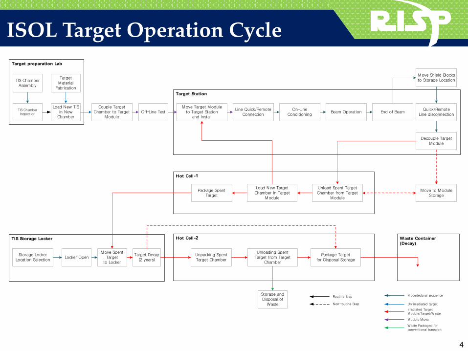
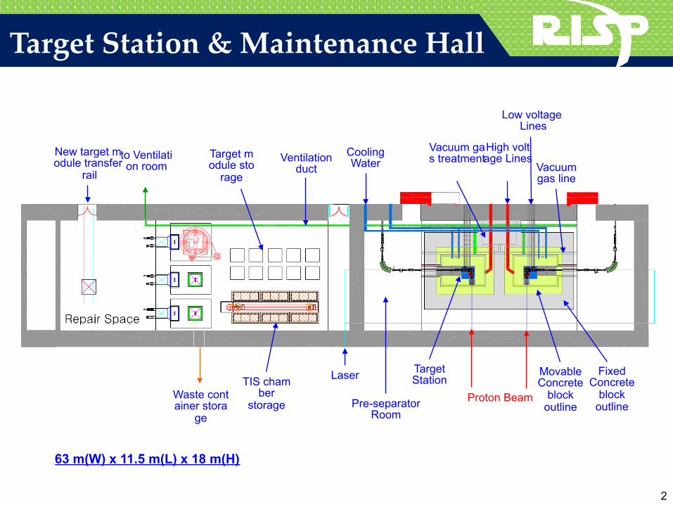
ISOL Target Operation Cycle Target preparation Lab
Target Station
Hot Cell
TIS Storage Locker Hot Cell Waste Container(Decay)
TIS Chamber Assembly
TIS Chamber Inspection
Target Material
Fabrication
Load New TISin New
Chamber
Couple Target Chamber to Target
ModuleOff-Line Test
Move Target Moduleto Target Station
and Install
Line Quick/Remote Connection
On-Line Conditioning
Beam Operation End of Beam
Move Shield Blocksto Storage Location
Quick/Remote Line disconnection
Decouple TargetModule
Load New Target Chamber in Target
Module
Unload Spent TargetChamber from Target
Module
Move to Module Storage
Package Spent Target
Storage LockerLocation Selection
Locker OpenMove Spent
Targetto Locker
Target Decay(2 years)
Unloading SpentTarget from Target
Chamber
Unpacking SpentTarget Chamber
Storage and Disposal of
Waste
Routine Step
Non-routine Step
Procededural sequence
Un-irradiated target
Irradiated Target Module/Target/Waste
Module Move
Waste Packaged forconventional transport
Package Target for Disposal Storage
4
-1
-2

ISOL Target Module § Vacuum Chamber & Target Module § Primary Vacuum zone : Target chamber & Beam line § Secondary vacuum zone : Module external volumes § Three Special All metal gate valves § Three Pillow Seals : Inter module connection § High Voltage Tray - Insulation : BN Powder or Arocy L-10 cyanate ester resin - Feedthroughs & Quick/Remote connectors § Shielding Materials : Heavy Concrete Block
Secondary Vacuum Zone
Primary Pumping Zone
Vacuum Chamber
Pillow Seal Pillow Seal
High Voltage Duct
Low Voltage Duct
All Metal Gate V/V
< Target Module, 1.4 m(W) x 1.5 m(L) x 3.3 m(H) >
Proton Beam
< Remote Multi Connection Panel (Designed by STAUBLI) >
< Pillow Seal (technical assistance by KEK) >
< Extended All Metal Gate Valve >
Remote Connector
5
Concrete Shielding

Target Module & Target Station Overview
< Target Station Concept >
10 kW Faraday Cup
Ø45 mm Collimator
< Proton Beam Diagnostic Module >
< RI Beam EQT Module >
< RI Beam Diagnostic Module >
< Target Module >
< Vacuum Chamber and TM >
< Front-end System component > 6

ISOL Target Hall Remote Crane Main remote crane use for : - Target Module & shield block removal / replaceme
nt - Target chamber transfer - Waste target handing - maintenance
ITEM SPECIFICATION REMARK
Lifting capacity 20T / 3T / 3T
Actual Lift 18/17.2/17.2 m
Operation Mode Normal / Emergency
Lifting speed 1mm/s to 100mm/s
Control dirve x-y-z
Rotation 360°
Rotation speed 1.2 rpm
Position accuracy 2mm Rack Gear
Lifting indicator 20 kg precision
Emergency capacity DC motor (with battery)
Safety & Control : - Auto/ manual/ Semi-Auto (with vision system) - Snag detection / Auto Centering (Vision system) - Reverse rotation prevention (hydraulic disc brake) - Auto switching to DC Motor when motor failure occurs - Operation Speed variable - Dual position encoders - All control devices located outside Target hall 3 Ton Hoist
(Steel Pail Connected)
Rotating Block
Coupling Gripper
3 Ton Hoist (maintenance) Sheave
Alignment Pin
7

Crane Interface Device
Rotating & Crane Hook Shaft
Rotating Motor Case
Guide Pin
Guide Pin Hole & Lock Mount
Vision
Alignment Guide Pin
Twist Lock Interlock
§ Remote interface of Target Module & Shield Blocks § Modularize for all components and prevent from radiation e
xposure § Interlock & Safety
1) Alignment check after transfer to Target Module & Shield Block
2) Move to alignment point 3) Move down & combine alignment pin with hole 4) Displacement & interlock sensing 5) Lock on
Twist Lock Actuator Case
Displacement
8
* Twist rock system used at J-PARC Hadron Facility

Target Module Remote Removal Concept Remote Crane
Interface Device
SB SB : Shield Block TC : Target Chamber TM : Target Module VC : Vacuum Chamber RC : Remote Connector ROM : RIB Optics Module BDM : Beam Diagnostic Module SP : Shielding Plug : Pillow Seal : Gate Valve
1) Remove shielding blocks of service zone 2) All metal gate valve close 3) Decouple Pillow seals 4) Break secondary and primary vacuum by Ar gas 5) Purge cooling waters from duct 6) Quick/remote disconnect all electric cables, water cooling / gas lines 7) Connect target module to remote crane and unload target module in va
cuum chamber 8) Move to hot cell 9) Put the target module in hot cell and decouple the crane 10) Insert a shielding plug into vacuum chamber
9
Pre-separator Room
Pre-separator Room
Target Station TM Storage Hot Cell

Target Exchange in Hot Cell
① Target module down to Hot cell-1 by 20 ton crane and position fixing ② Unload spent target chamber from target module by manipulator New target chamber couple to target module ③ Lift target module ④ Move pail to transfer point along guide line ⑤ Insert spent target chamber in pail by gripping tool connected to manipulator ⑥ Lift pail by gripper(3 ton crane) and move to storage locker
①
② ③
④ ⑤
⑥
10

Spent Target Storage
< ISAC/TRIUMF Target Storage Vault >
< ARIEL/TRIUMF Target Storage Vault >
Pail(Spent Target Chamber) I/O Port
Rack Master
< Target Chamber Stocker system >
Crane Interface Device
Shelf & Frame
Pail(Target Chamber)
Lock Mount
- 1,140(W) x 12,690(D) x 3,150(H) - Stroke : A-axis 750 mm, R-axis 180° - Payload : Normal 30 kg - Gripper : Hanger type
Guide Line
11
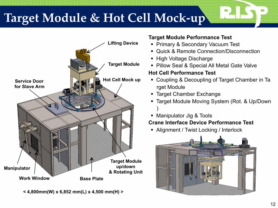
Target Module & Hot Cell Mock-up Target Module Performance Test § Primary & Secondary Vacuum Test § Quick & Remote Connection/Disconnection § High Voltage Discharge § Pillow Seal & Special All Metal Gate Valve
Hot Cell Performance Test § Coupling & Decoupling of Target Chamber in Ta
rget Module § Target Chamber Exchange § Target Module Moving System (Rot. & Up/Down
) § Manipulator Jig & Tools
Crane Interface Device Performance Test § Alignment / Twist Locking / Interlock
Lifting Device
Target Module
Hot Cell Mock up Service Door for Slave Arm
Manipulator
Work Window
Target Module up/down
& Rotating Unit Base Plate
< 4,800mm(W) x 6,852 mm(L) x 4,500 mm(H) >
12
13
Summary
§ RISP ISOL systems are being developed for providing n-rich RI beam to user facility
§ Detail and Engineering Design of ISOL remote handling system including infrastructure under way
§ Final Goal : 70 kW UCx Target Ion Source system (in RISP 10 kW) § Start install in 2019, 2021 RI beam providing § Benchmarked the TRIUNF target module and remote handling system § Target remote handling scenario defined § All remote procedures to be mocked-up and tested prior to commissionin
g with beam. § Target module and hot cell mock-up in progress of manufacture
Thank you for your attention !