Embed Size (px)
Citation preview

Mitsubishi Heavy Industries Technical Review Vol. 49 No. 4 (December 2012) 44
*1 Engineering Manager, Engineering Division, Bridge Headquarter, Mitsubishi Heavy Industries Bridge & Steel Structures
Engineering Co., Ltd.
*2 Engineering Division, Bridge Headquarter, Mitsubishi Heavy Industries Bridge & Steel Structures Engineering Co., Ltd.
*3 Research Director, Coastal and Ocean Engineering Field, Port and Airport Research Institute
*4 Chief Engineer, Design Department No. 3, Civil Engineering Technology Division, Obayashi Corporation
*5 Senior Manager, Nippon Steel & Sumikin Engineering Co., Ltd.
*6 Manager, Design Department, Civil Engineering General Headquarters, Toa Corporation
Development of Vertical Telescopic Breakwater that Rises from Seabed in Emergencies
KAZUYOSHI KIHARA*1 TSUTOMU MAEKAWA*2
TARO ARIKAWA*3 MAKOTO KOBAYASHI*4
HIROHIDE KIMURA*5 HIROSHI INOUE*6
The mouths of ports and harbors are open to allow vessel passage. There is apprehension
about the serious damage that can be caused by tsunamis or high tides entering through the mouthand running up not only rivers, but also on land. This report introduces the “Vertical TelescopicBreakwater (VTB)” developed for the solution of these problems. The VTB is a line of cylindricalstructures, each of which consists of an upper steel pile and a lower steel pile, and they are stored in the seabed in normal times. The upper piles are raised during emergencies such as tsunamis andhigh tides. The VTB allows the prompt opening of port channels by lowering the upper piles afterthe disaster has been averted.
|1. Introduction
In our country, population and city functions are concentrated along coastal areas. The risk ofdisasters such as tsunamis and high tides has been increasing year by year, especially since theMarch 11 Great East Japan Earthquake and due to the imminence of To-kai, Tonan-kai and Nan-kai (eastern, south-eastern and southern seas) earthquakes, as well as rising sea levels andtyphoons growing in size brought about by global warming.
Breakwaters of ports and harbors in Japan have been upgraded to protect lives and property from disasters such as tsunamis and high tides. At the same time, ports and harbors must provide apassage for vessels through an opening. As a result, it is inevitable that ports and harbors arevulnerable to tsunamis and high tides entering through the mouth.
Figure 1 Features of Vertical Telescopic Breakwater (VTB)

Mitsubishi Heavy Industries Technical Review Vol. 49 No. 4 (December 2012) 45
The VTB is a movable breakwater that can solve these problems. The VTB can be storedunder the seabed to allow the free passage of vessels in normal times, and is raised above the sea surface in a tsunami or high tide emergency to shut the mouth and shield the port against surgingwater, as shown in Figure 1.
This VTB has been developed as a joint effort of the public and private sectors by organizinga coordinated study group consisting of four private companies; Obayashi Corporation, TOACorporation, Nippon Steel and Sumikin Engineering and Mitsubishi Heavy Industries, Ltd., and thePort and Airport Research Institute, which is an Independent Administrative Institution under MLITT.
|2. Structure and Features 2.1 Outline of structure
The VTB has a telescopic structure consisting of lower steel piles installed in the seabed andupper steel piles (movable pipes), which can be raised and lowered, inserted in the lower pile (Figure 2). The upper piles are arranged in line to form a tide barrier. Gaps of several centimetersbetween the upper piles remain for the installation of lower piles with a larger diameter. As a result,a series of small openings is provided along the whole length of the breakwater.
The gaps can partially reduce their opening rate with gap-clogging auxiliary pipes against upcoming waves (Figure 3).
The lower piles installed in the seabed are connected to air pipes from an air supplyingfacility on land.
Air is supplied to the inside of the upper piles installed in the seabed. The upper piles start torise when the internal air pressure in the piles exceeds the effective weight of the piles. The pilesprotrude above the sea surface and stop at the height of stoppers installed in the lower piles. The lowering of the piles is carried out by venting the air from the upper piles through the exhaust valveinstalled at the top of the piles. The raising and lowering speeds are controllable by adjusting the air supply rate and air venting rate.
Figure 2 Sectional View of Vertical TelescopicBreakwater (VTB)
Figure 3 Improvement of shielding rate by installing auxiliary pipes
2.2 Features
The raising and lowering of the breakwater can be controlled by operating the supply andventing of air to the upper piles as explained above.
(1) The breakwater is normally installed in the seabed to allow the free passage of vessels. Inaddition, the breakwater does not affect the sea tides or ocean currents, and the exchange ofsea water in the harbor is also not impeded.
(2) The raising and lowering of the upper piles do not require a large scale driving facility,rather a simplified mechanism that is easily maintained that supplies and vents highlypressurized air.

Mitsubishi Heavy Industries Technical Review Vol. 49 No. 4 (December 2012) 46
(3) The breakwater is installed in the seabed, which ensures a high level of safety against earthquakes.
(4) The materials used are widely used steel pipes, ensuring high reliability and safety. These features of this breakwater installed at the mouths of ports and harbors (ship route)
enable both protection against disasters caused by tsunamis and high tides, and improve operationalrates of cargo handling by ensuring calmness in the harbor. Possible applications of the utility ofthis breakwater are shown in Figure 4.
Figure 4 Examples of VTB Installation
|3. Structure and Features The technical problems below caused by structural characteristics must be solved for the
development of this breakwater. Both hydraulic model experiment1,2 and field tests3 in Numazu Port were conducted to solve the problems. An intensive investigation was also made on the reinforcement structure at the upper-lower overlap position.
(1) The gap between the upper piles is inevitable because of VTB installation restrictions, making the verification of the shielding effectiveness as a breakwater necessary.
(2) The transition mechanism of horizontal stress caused by incident waves, which the upperpile receives, must be clarified, and the stress at the overlap of upper and lower piles must be understood.
(3) The adhering condition of marine growth on the upper piles during lengthy periods ofstorage in the lower piles, as well as the anti-corrosion durability of the construction materials, must also be verified.
3.1 Hydraulic model experiment A hydraulic model experiment was conducted to clarify the wave protection effect using a
Large Hydro Geo Flume (length: 184 m, depth: 12m, width: 3.5m) at the Port and Airport ResearchInstitute. Experiments were conducted under the conditions of a 1/5 scale model and the openingrates were 0.05, 0.1 and 0.15 for wind waves and tsunamis. The opening ratio (α) is defined as; α =b/(B+b) (b: gap width between the pipes, B: pipe diameter). A picture of the experiment is shown in Figure 5.
Figure 6 shows the relationship between the upper pile opening rate(α) and the transmissioncoefficient of the waves. The figure shows a larger opening rate results in a larger transmissioncoefficient (passed wave height after breakwater/incident wave height). The transmission coefficient differs with the wave period. In the case of an opening rate 0.05, the transmissioncoefficient can be reduced to 0.35 to 0.40 for wind waves, and 0.25 to 0.30 for tsunamis. Inaddition, the transmitting flow rate to the back of the breakwater (inside the port) can be roughlycalculated by deriving the relationship between the opening rate and flow velocity at the openingfrom the results of the experiments (Figure 6).

Mitsubishi Heavy Industries Technical Review Vol. 49 No. 4 (December 2012) 47
Figure 5 Hydraulic model experiment (against tsunami wave)
Figure 6 Relation between the upper pile opening rate and transmission coefficient
3.2 Verification test in real sea area
A test facility was installed in front of a caisson of Numazu Port in Shizuoka prefecture in September, 2006 for the verification test in a real sea area, and the test was conducted for aboutthree years. (Figure 7).
Upper steel pile(movable pipe)
φ1422mm L=14.75m
Lower steel pile φ1600mm L=16.75m
Fixed pile φ1422mm×2 pcs
(installed by Shizuoka prefecture)
Water depth 7.5 m Top of upper
pile3.25 m above sea surface
Floatingequipment Compressor and air pipes
Figure 7 Horizontal layout of verification test facilities
(1) Outline of test facility The first year in the three-year verification test, fundamental performances such as
mobility, hydraulic and dynamic characteristics were verified. In the second year, the upper piles were raised for the investigation of marine growth and steel material degradation after oneyear of being submerged. Also in May of 2009, two and a half years after installation, aninvestigation of the dissolved oxygen concentration in the lower pile, verification of the system equipment for the opening/closing of the exhaust valves and other verification tests wereconducted in addition to the second year tests4.

Mitsubishi Heavy Industries Technical Review Vol. 49 No. 4 (December 2012) 48
(2) Test results [1] Manufacturing of steel pipe and processing accuracy
The upper pile was made by welding four kinds of steel pipes of different thicknesses.The concentricity of pipes, which was the most important factor, was 0 mm, and goodcircularity was ensured.
The lower pile was driven into the seabed with a vibrohammer, and very good vertical accuracy for placement was attained with the help of the installation of guide members.
[2] Raising and lowering test The mobility verification was mainly conducted in 2006, mainly focusing on lowering
tests. After leaving the breakwater for three years, the remote air supply/venting equipmentwas installed, and an investigation on the raising time was conducted. The system reliabilitywas verified to be free from problems during more than one hundred raising/lowering tests.Figure 8 shows the situation of a raising test in the field.
Figure 8 Situation of raising test in the field [3] Hydraulic and dynamic characteristic test (response test in ocean waves)
Impact forces expected to be applied to the contacting points between the upper andlower piles, and fatigue problems caused by repeated load due to the shaking of the upperpiles were a concern. The acceleration of the piles, wave pressure applied to the front/back faces of the upper piles and strain around the overlap between the upper/lower piles weremeasured continuously for approximately two weeks. Figure 9 shows the field conditions.
Figure 10 shows the concept of the numerical model of upper pile floating body movement in ocean waves. Analyses were conducted for the impact response of the upperpiles. Figure 11 shows a sample of the simulation results, and good reproduction of upperpile movement can be seen. A schematic illustration of the force balance along the upper pile is shown in Figure 12.4,5
[4] Marine growth The upper pile was raised after approximately one year from the last lowering of the
breakwater, and an investigation of marine growth was conducted. Acorn shells of 1 to 2 mmthick were observed on the top cap, but close to nothing was observed on the side face of thepile. This is believed to be due to the low dissolved oxygen (2 ppm measured) concentrationin the lower pile.
Figure 9 Response test in ocean waves Figure 11 Acceleration of upper pile in ocean waves

Mitsubishi Heavy Industries Technical Review Vol. 49 No. 4 (December 2012) 49
Figure 10 Concept of numerical model of upper pile floating body movement in ocean waves
Figure 12 Outline of load applied
3.3 Structural reinforcement at overlap
The overlap transfers the load acting from the upper pile to the lower pile as shown in Figure12. The upper and lower ends are the points where stress is concentrated (reaction force point), andreinforcement in the pile sectional direction is required in addition to an increase in the wallthickness of the pile base metal. An investigation using 3-dimensional elastoplasticity FEM analysis (ABAQUS solid model), which can consider large deformations and points of contact, wasconducted.6
Figure 13 shows the results of the analysis at the overlap where tsunami power is applied asdesign load under the conditions of a lower pile diameter of 3,000 mm (thickness 60 to 45 mm) and an upper pile diameter of 2,800 mm (wall thickness 28 to 32 mm). The reinforcement was verifiedto be appropriate as the steel pile and reinforcement are within the yield stress, and the maximumstress is generated at a general position above the overlap. In addition, further analysis byincreasing the load from the conditions in Figure 13 was conducted for the verification of bearingcapacity.
Figure 13 Result of FEM analysis
Figure 14 shows the load to deformation relationship, and Figure 15 shows the fractured deformation condition after reaching the maximum bearing capacity. With an increased load, theyield area is expanded. However, the load could be increased to the point of 2.6 times of the supposed design value without a sudden fall of bearing capacity. The final deformation shape wasthe buckling at the position above the overlap. This indicates further reinforcement can be attainedby extending the thick-wall area upward.

Mitsubishi Heavy Industries Technical Review Vol. 49 No. 4 (December 2012) 50
Figure 14 Load-deformation relationship Figure 15 Deformation conditions when the maximum load is applied
|4. Approach to simplification of air supply and shorter raising timeWith the results of the tests, labor saving efforts on operation were conducted for practical
application. In addition, in the tsunami re-prediction results of the Central Disaster Prevention Council after the East Japan Earthquake on March 11, 2011, the predicted arrival times of tsunamiswill become shorter than current predictions. So, a new simulation program, which allowsparametric study, was developed for the improvements such as a shorter raising time.7 4.1 Miniaturization of air supply facility
We found a water-tight tank (buoyancy tank) installed in the upper pile can reduce theamount of air supply required to raise the upper pile. It also shortens the raising time and downsizes the capacity of accumulator to preserve supply air.
In addition, for the reduction of equipment such as the number of air supply pipes, threeupper piles are connected at the top as a single set. Simply supplying air to just the center pile canraise the three piles simultaneously as shown in Figure 16.
With the application of the measures noted above, the simplification of construction and thereduction of potential problems with air pipes have become possible.
Figure 16 Outline of connected three-pile structure
Figure 17 External forces applied to raising steel pile
Mitsubishi Heavy Industries Technical Review Vol. 49 No. 4 (December 2012) 51
4.2 Air supply and raising simulation (1) Air supply simulation
In the study of raising time estimation, the estimation of the air discharge speed of thecompressed air (supplied air amount) at the bottom of the lower piles is required. Thedischarge air speed is mainly determined by the energy loss resulting from pipe friction through the air pipe from the land facility to the lower pile bottom end. Using thefundamental formulas of air flow (equation of continuity, energy conservation law andmomentum conservation law), and composing the discharge system by sequential computation of minute segments along the supply pipe, we developed the “Air SupplySimulation Program” to calculate the discharge speed
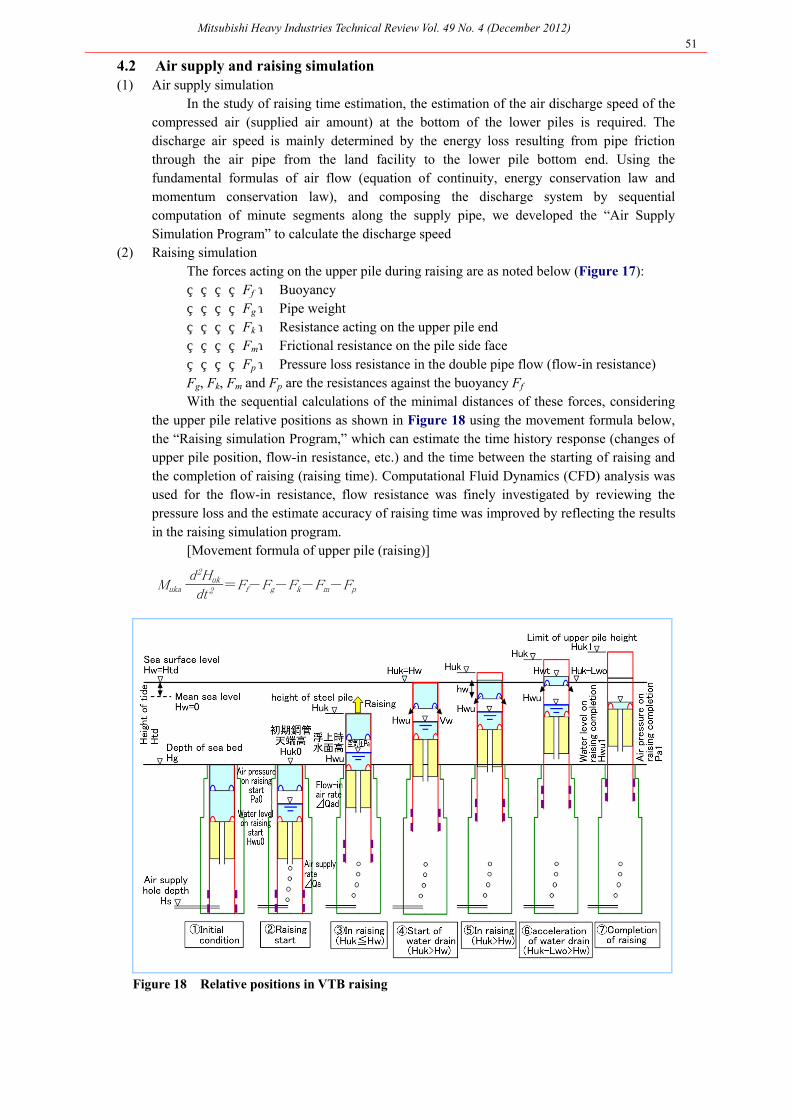
(2) Raising simulation The forces acting on the upper pile during raising are as noted below (Figure 17): Ff : Buoyancy Fg : Pipe weight Fk : Resistance acting on the upper pile end Fm : Frictional resistance on the pile side face Fp : Pressure loss resistance in the double pipe flow (flow-in resistance) Fg, Fk, Fm and Fp are the resistances against the buoyancy Ff With the sequential calculations of the minimal distances of these forces, considering
the upper pile relative positions as shown in Figure 18 using the movement formula below, the “Raising simulation Program,” which can estimate the time history response (changes of upper pile position, flow-in resistance, etc.) and the time between the starting of raising andthe completion of raising (raising time). Computational Fluid Dynamics (CFD) analysis wasused for the flow-in resistance, flow resistance was finely investigated by reviewing the pressure loss and the estimate accuracy of raising time was improved by reflecting the resultsin the raising simulation program.
[Movement formula of upper pile (raising)]
Muka d2Huk =Ff-Fg-Fk-Fm-Fpdt2
Figure 18 Relative positions in VTB raising

Mitsubishi Heavy Industries Technical Review Vol. 49 No. 4 (December 2012) 52
(3) Verification of raising simulation In the verification of the raising simulation program, a comparison was made to the
VTB hydraulic model experiment conducted at the Port and Airport Research Institutedescribed in section 3. The verification test in the field was conducted from 2006 to 2009.The program was well verified as following the test results to a high degree of accuracy.(Figure 19)
Figure 19 Comparison between verification test in ocean waves and raising simulation
4.3 Method to reduce raising time An investigation to reduce the raising time of the three-pile combined VTB shown in Figure
16 was conducted by utilizing the developed raising simulation program. The investigation focusedon the Fp (pressure loss resistance – flow-in resistance of double pipe inside flow) which is a structural feature of VTB.
The sea water pushed aside needs to flow into the upper and lower piles when the upper pileis being raised. The sea water flowing into the lower pile (Figure 17) flows both through theclearance between the lower piles and upper piles, and flows through the connecting pipe installed at the center pile. The reduction of raising time by applying improvements to each flow route belowwas investigated. (1) Expansion of clearance between upper and lower piles
A stabilizer is installed at the top of each lower pile to adjust the clearance with the upper pile. The clearance must be increased to lower the flow-in resistance. However, the larger clearance adversely affects the pile collision in high wave. Accordingly, the clearancewas limited to 20 mm or less, and the shortening of raising time was investigated in relation to the change of clearance.
(2) Expansion of connecting pipe diameter and installation of connecting pipe to each pile An increase of flow-in in the amount of sea water through the connecting pipe is
thought to be effective in reducing the flow-in resistance. Accordingly, the expansion of connecting pipe diameter and the installation of connecting pipes in side piles as additionalnew sea-water flow-in routes were verified for the shortening of raising time. Under the conditions of a lower pile diameter of 3,000 mm and an upper pile diameter of
2,800 mm, the clearance was increased from 15 mm to 20 mm as a countermeasure (1), and theshortening of raising time was calculated. The result showed a significant reduction of raising time from approximately nine minutes before the improvement to five and half minutes.Countermeasures (1) and (2) above were verified to be effective in reducing the raising time byusing the raising time simulation program.

Mitsubishi Heavy Industries Technical Review Vol. 49 No. 4 (December 2012) 53
|5. Tsunami Countermeasures Project in Kainan-Area, Shimotsu Port Coast in Wakayama Prefecture The Kainan area near the Shimotsu Port coast in Wakayama prefecture is located at the bay
end of a deeply-indented coast line, and has suffered from floods from tsunami due to its geographical characteristics in past years. In addition, a tsunami significantly exceeding the currentbreakwater height is expected to come in the predicted of Tonan-kai and Nan-kai earthquakes, which have a high probability of occurrence in the next 30 years. Important administrative institutions, disaster prevention agencies and main transportation networks, in addition toresidential areas and businesses, are located in the predicted tsunami immersion area on the coast.Countermeasures against tsunami are greatly desired.
Raising the bank of the current seawall will cause significant problems for the cargo handlingof vessels. Accordingly, the tsunami protection project through the installation of VTB at themouth of the port, forming a line of defense in front of the predicted immersion area is under way.
|6. Conclusions Parts of the outline and technical development of VTB developed from 2004 are introduced
in this report. The East Japan Earthquake occurred on March 11, 2011, recording 9.0 on the Richter scale,
the worst in Japan’s history. A huge tsunami was generated by this earthquake, and coastal areasfacing the Pacific Ocean in Tohoku and Kanto suffered from the catastrophic disaster. The invasionof a huge tsunami of more than 30 m in height is predicted in Kouchi and Shizuoka Prefectures according to the tsunami predictions announced by the Central Disaster Prevention Council.
As described above, the susceptibility of coastal areas against tsunami has been pointed out.We would like to continue the study to utilize the VTB technology and evaluate it as a reliablebreakwater in the future.
We would like to extend our acknowledgment to those people who provided support andcooperation in the development of the Vertical Telescopic Breakwater (VTB).
Special acknowledgments:
We deeply appreciate the significant support of people in the Numazu Civil EngineeringOffice of the Ports and Harbors Bureau in the Shizuoka Construction Department, Dr. Yoshiaki Kikuchi, the former director of the Geotechnical and Structural Engineering Department at the Port and Airport Research Institute, Independent Administrative Institution (currently a professor atTokyo University of Science), as well as the other individuals involved in the real sea areaverification tests in Numazu Port.
References 1. Arikawa, T. et al., Material from Port and Airport Research Institute, No.1156, June 2007 2. Arikawa, T. et al., Proceedings of Civil Engineering in the Ocean Vol. 23 (2007), pp. 117-122 3. Arikawa, T. et al., Proceedings of Civil Engineering in the Ocean Vol. 24 (2008), pp. 93-98 4. Kihara, K. et al., Development of Vertical Telescopic Breakwater, Mitsubishi Heavy Industries Bridge &
Steel Structures Engineering Technical Review (MBE Giho), (2009) 5. Kihara, K. et al., Proceedings of Civil Engineering in the Ocean Vol. 25 (2009), pp.99-104, 6. Maekawa, T. et al., Material from Japanese Association for Coastal Zone Studies (2011) 7. Maekawa, T. et al., Material from Japanese Association for Coastal Zone Studies (2012)