Embed Size (px)
Citation preview
J J 1J J
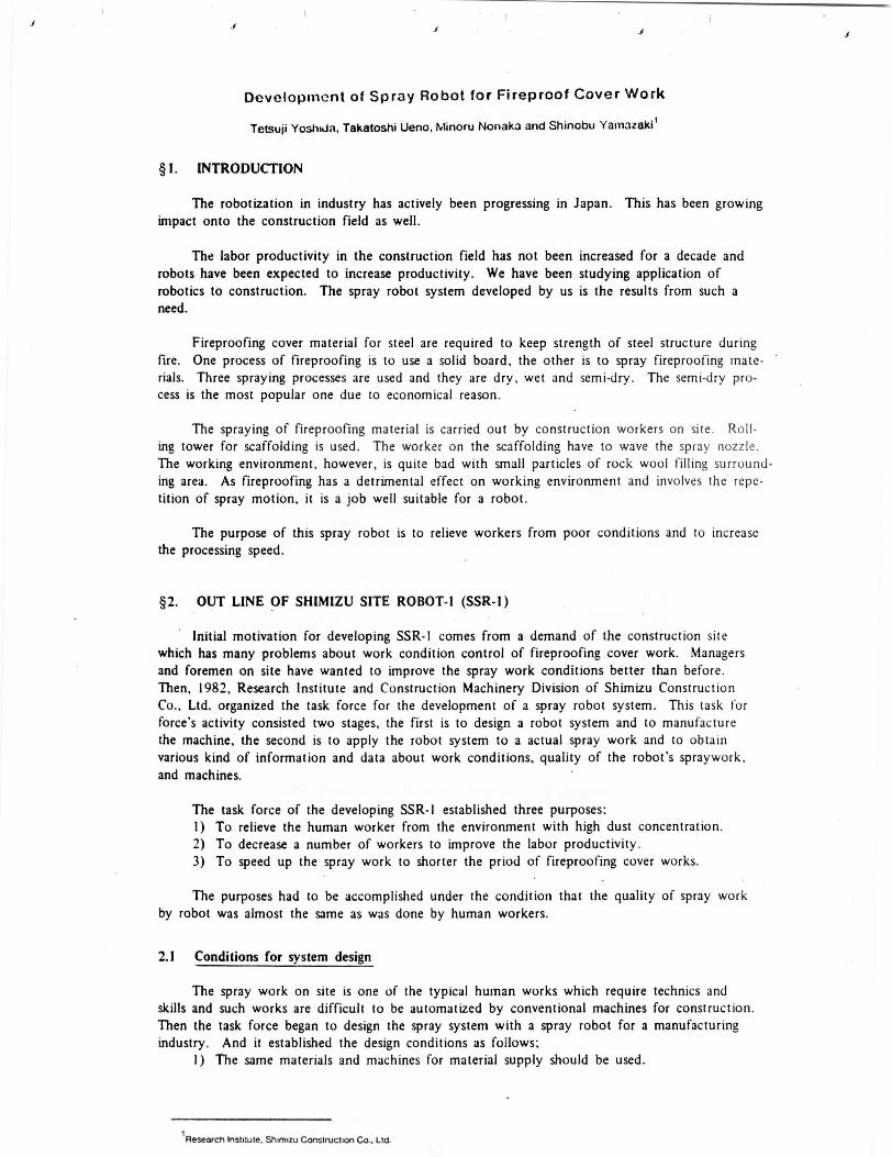
Development of Spray Robot for Fireproof Cover Work
Tetsuji Yoshida, Takatoshi Ueno, Minoru Nonaka and Shinobu Yamazaki'
§ 1. INTRODUCTION
The robotization in industry has actively been progressing in Japan. This has been growingimpact onto the construction field as well.
The labor productivity in the construction field has not been increased for a decade androbots have been expected to increase productivity. We have been studying application ofrobotics to construction. The spray robot system developed by us is the results from such aneed.
Fireproofing cover material for steel are required to keep strength of steel structure duringfire. One process of fireproofing is to use a solid board , the other is to spray fireproofing mate-rials. Three spraying processes are used and they are dry, wet and semi -dry. The semi-dry pro-cess is the most popular one due to economical reason.
The spraying of fireproofing material is carried out by construction workers on site. Roll-ing tower for scaffolding is used. The worker on the scaffolding have to wave the spray nozzle.The working environment, however, is quite bad with small particles of rock wool filling surround-ing area . As fireproofing has a detrimental effect on working environment and involves the repe-tition of spray motion , it is a job well suitable for a robot.
The purpose of this spray robot is to relieve workers from poor conditions and to increasethe processing speed.
§2. OUT LINE OF SHIMIZU SITE ROBOT- I (SSR-1)
Initial motivation for developing SSR-I comes from a demand of the construction sitewhich has many problems about work condition control of fireproofing cover work . Managersand foremen on site have wanted to improve the spray work conditions better than before.Then, 1982, Research Institute and Construction Machinery Division of Shimizu ConstructionCo., Ltd. organized the task force for the development of a spray robot system . This task forforce 's activity consisted two stages , the first is to design a robot system and to manufacturethe machine , the second is to apply the robot system to a actual spray work and to obtainvarious kind of information and data about work conditions , quality of the robot ' s spraywork,and machines.
The task force of the developing SSR-I established three purposes;1) To relieve the human worker from the environment with high dust concentration.2) To decrease a number of workers to improve the labor productivity.3) To speed up the spray work to shorter the priod of fireproofing cover works.
The purposes had to be accomplished under the condition that the quality of spray workby robot was almost the same as was done by human workers.
2.1 Conditions for system design
The spray work on site is one of the typical human works which require technics andskills and such works are difficult to be automatized by conventional machines for construction.Then the task force began to design the spray system with a spray robot for a manufacturingindustry. And it established the design conditions as follows;
1) The same materials and machines for material supply should be used.
1Research Instiute, Shimizu Construction Co., Ltd.

2) The robot must have mobility.3) The robot should work sequentially and continuously without human help.4) The robot should be capable of travelling and positioning on the dusty and dirty floor.5) The weight of the robot should be within the limit of design load (300 kgf/m2 ).6) The size of the robot should be determined according to a size of the lift cage to be
set up on site.7) The robot must have safety functions for human workers, finished building (floor,
girders and beams, pillars, curtain walls, glasses, and so on), and the robot itself.
The task team has chosen the system among several alternatives.
In Japan, manufacturers are providing many types of playback robots. KTR-3000F(KOBE LCO-TRALLFA SPRAY ROBOT ) was introduced because the specifications listed beloware satisfied.
1) To have large quantity of the menory device to be able to memorize many spraypatterns.
2) To be able to carry the nozzle for spray more than 2 - 3 kgf (5 kgf enough).3) To be able to use the continuous pass (CP) control for teaching the robot.
2.2 System structure of the spray system using SSR- l
The spray system has material supplying plant and SSR-I for spray works.
Material supply
Materials for fireproofing ( semi-dry type) are rock wool and cement milk. Rock woolwhich is poured into the feeder is carried upward on the air flow created by the blower.The air with rock wool goes into the wool agitator through the flexible hose (3 inch dia.).The flow with rock wool is stabilized when air goes through the wool agitator.
Cement milk is prepared in the cement mixer . The weight ratio of the water and cementis about 2: 1. The cement milk is pumped up through 1 /4 inch flexible hose.
The material supplying plant is located on the 1st floor or on the basement, less than about100m below the spray works. (Fig.I )
Manipulator
The manipulator can be put in action programs directly by manual.
The spray robot consists of four main components: base, vertical arm, horizontal armand wrist. This manupulator has 6 freedoms driven by the playback control system consistingof electro-hydraulic servo control.
The hight and width of the moving area is about 2m x 3nt. Because of the tlwxiblewrist type, teaching works are not difficult in this moving area. Control wires. hydraulichoses and material hoses are mounted on the supporters which are set every I in interval.As these supporters can move smoothly on the floor. hoses and cables are protected fromwearing out.
70

f
Traveller
The manipulator is mounted on the traveller which is made of an alloy of aluminiumwith higher strength than normal aluminium . Then the traveller 's weight is 220kgf.
The traveller has 4 outriggers with wheels and the robot can stand vertically whentravelling.
Control Equipment
The manipulator has a control equipment for itself, and the traveller has a sequentialcontroller which controlls the traveller and the manipulator.
The manipulator control equipment (CRC system = Computer Robot Control) has CP'PTPteaching and CP play back control functions. CRC controller consists of one pair of floopydisc drive unit and other computer circuits. CRC system allows 64 programs and the maximumprogramming capacity is 128 minuts.
Connecting the CRC system with the sequential controller, SSR-I can playback and re-peat the many kinds of programs . The total possible working time is lower than 2 hours.
The traveller control equipment has also the oscillator for the tractor guiding and steering.
Tractor
The tractor is driven by electric power of batteries (DC 24V charging every 8 hours)and guided by the path wire which is connected to the electromagnetic induction oscillator(3.5kHz). For the sensing of the magnetic field of the path wire, one pair of the coil isattached to the front axle. One magnetic switch that can recognize a iron plate (80 x 80 x 10is also attached to the front axle and for the sensing of the stopping point of the tractor.
This tractor can be operated by manual and antomatic, changing the mode switch onthe tractor or on the controller.
§3. SPRAYING RESULTS AND PROBLEMS OF SSR-1
3.1 Outline of the spraying work
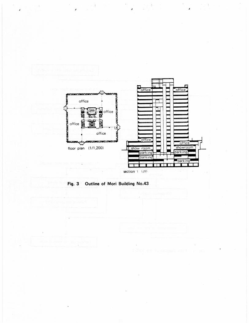
SSR-I was applied on The 43rd Mori Building . This building is suitable for SSR-I because
the beam distances are all 3.1 meters per module. The chart of the spray work is shown in
Fig. 4.
The travelling path of SSR-I is shown in Fig.5. The curve path was determined by trialand error.
We programmed chart of the spray work on the controller which can control travelling.stopping and spraying.
71

J
3.2 Results of the application ( SSR-1)
3.2.1 Work conditions
We measured the dust concentration as an index for working conditions. A digital dustmeter and a low volume air sampler were used for the measurements.
The conventional coefficient of the mass concentration K (mg/m3) is determined by the
digital dust meter and the optical disperse concentration C (CPM; Count Per Minute). Thenwe calculate the mass concentration M (mg/m3 ).
M=K•C
Fig.6 shows the results of dust measurements. The dust concentration depends on thedistance from the nozzle.
3.2.2 Work Efficiency
We evaluated the work efficiency by checking spray time per determined area. As aresult of this evaluation , it was found that the processing speed was almost twice as fast asthe conventional method.
Fig.7 shows a pareto diagram for preparing robot system. There are some new tasksinvolved. The placement of a wire path and a plate for stopping points and the lifting workof the robot system are not included in the conventional method.
3.2.3 Quality
The fireproofing ability is determined by the specific gravity of rock wool and thethickness of the materials . The specific gravity of rock wool must be greater than 0.3 andthe thickness of the fireproofing required is determined.
We found the specific gravity of rock wool sprayed by the robot is almost similar tothe one achieved by a human worker. The major points for discussion concerning the dispersionof the fireproofing are shown in Fig.S. The biggest problem is to uniformly supply thematerial for spraying.
§4. OUTLINE OF SSR-2
Following the SSR-1, the SSR-2 was developed to improve some functions of the SSR-1on jobsite. Main items for improvement are;
1) To introduce a new positioning system in relation to a beams to be sprayed.2) To travel and gyrate by the robot itself.3) The path wire for guiding the robot should be eliminated.4) To improve the feeder to be able to supply rock wool more uniformly.
Fig.9 shows the structure of the SSR-2.
The specification of SSR-21 are shown in Table 2.The main items improved are shown in Table 3.The outw ..ad figure is shown in Fig.10 and Photo 4.
72

e
4.1 Main components of SSR-2
(1) Manipulator
Fundamentally, the manipulator is similar to the SSR-I's, but to make the teachingtask easier, the serbo cylinders of the manipulator were replaced by the light friction typecylinder. The sensor for measuring distances was attached to the end of the robot arm.
(2) Travelling Device
The travelling device for the SSR-2 was designed to be able to gyrate at the same area.
The travelling device consists of the stand frame with 4 outriggers and the traveller framewith 4 wheels. The stand frame has 4 outriggers, hydroulic control valves, joint box for electricwires, sensors for collision avoiding and spacers for changing the height of the manipulator.The traveller frame has the gyrating and travelling drive units, and the sensor (rotary encoder)for measuring distances to be travelled. These 2 frames are connected at the center of theeach frame. These 2 frames enable the traveller to act as to go strait. stop, stand by 4 out-riggers, gyrate 0 90° right (or left), and so on.
(3) Control Device
The control device of the SSR-2 is composed of the manipulator controller and the travellingdevice controller.
The manipulator controller is as the same as the SSR-I's.
The travelling device controller is designed to control the travelling sequence and tocalculate the travelling position data (distance, height. angle).
These data are calculated by the 16 bit-computer control system (TM9995, 16KB ROM.14KB RAM ). In order to set the traveller at the initial position with good precision , the addi-tional pendant box for manual was attached to the traveller's controller.
(4) Device for supplying materials
We improved the device for supplying rock wool which influences the dispersion of thethickness of the fireproofing. The hopper of the rock wool feeder was attached to the addi-tional stirring shuttlecock and the vibrator.
4.2 Positioning method of the traveller
The positioning method of the traveller is the main character of the SSR -2. The path wirewas used for the SSR-I, however, the SSR-2 no longer need to follow any path wires.
The SSR-2 is able to travel by itself with the sensor for travelling distance . Even the SSR-2travels under program controls. slight deviation caused by the uneven surface of the floor. TheFig. I I shows the method of adjusting positions of the traveller.
The sensing device to confirm the positions, attached to the end of the manipurator's arum,consist of the potentiometer and the rod. The SSR-2 measures its position by pushing the rod
i3
J J 1
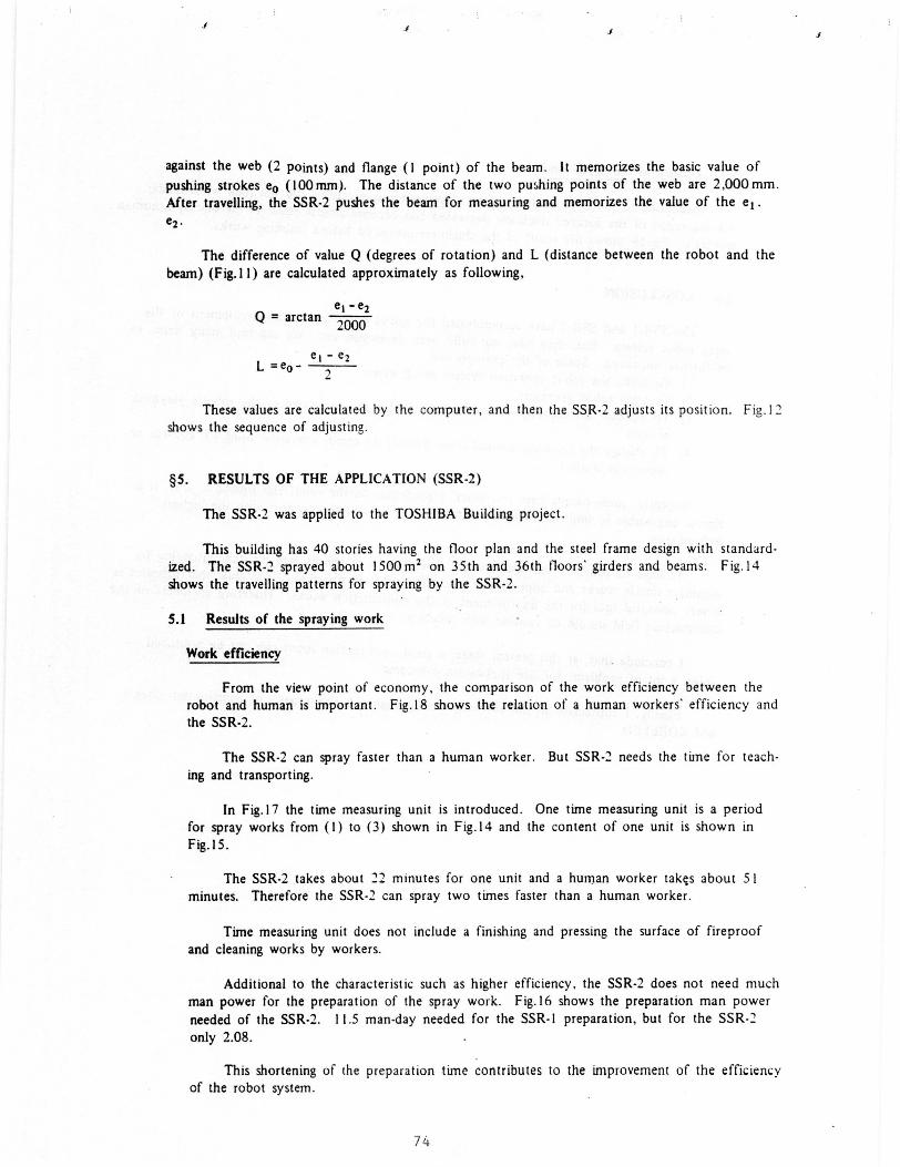
against the web (2 points) and flange (1 point) of the beam. It memorizes the basic value ofpushing strokes eo (100 mm). The distance of the two pushing points of the web are 2,000 mm.After travelling, the SSR-2 pushes the beam for measuring and memorizes the value of the el.e2.
The difference of value Q (degrees of rotation) and L (distance between the robot and thebeam ) ( Fig. 11) are calculated approximately as following,
n = arctanet -e22000
L =eo-et-e2
7
These values are calculated by the computer, and then the SSR-2 adjusts its position. Fig.12shows the sequence of adjusting.
§5. RESULTS OF THE APPLICATION (SSR-2)
The SSR-2 was applied to the TOSHIBA Building project.
This building has 40 stories having the floor plan and the steel frame design with standard-ized. The SSR-2 sprayed about 1500m 2 on 35th and 36th floors' girders and beams. Fig.14shows the travelling patterns for spraying by the SSR-2.
5.1 Results of the spraying work
Work efficiency
From the view point of economy, the comparison of the work efficiency between therobot and human is important . Fig.18 shows the relation of a human workers' efficiency andthe SSR-2.
The SSR-2 can spray faster than a human worker. But SSR-2 needs the time for teach-ing and transporting.
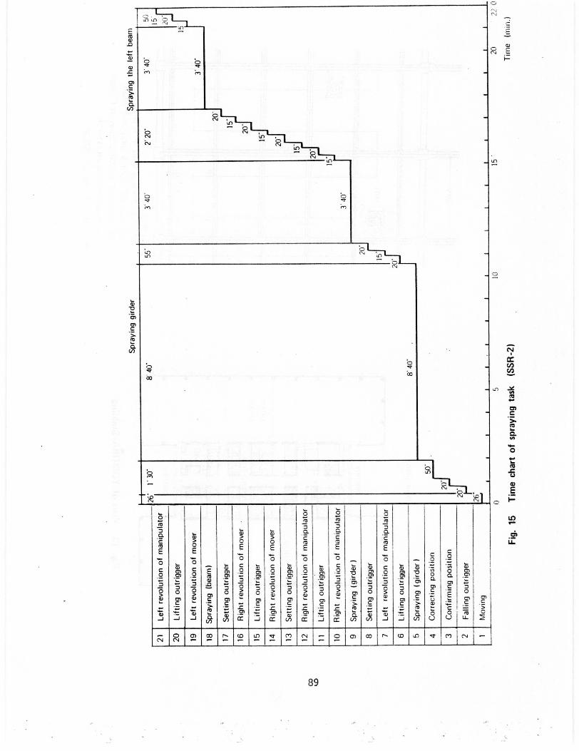
In Fig.17 the time measuring unit is introduced. One time measuring unit is a periodfor spray works from (I) to (3) shown in Fig.l4 and the content of one unit is shown inFig. 15.
The SSR-2 takes about 22 minutes for one unit and a human worker takes about 51minutes. Therefore the SSR-2 can spray two times faster than a human worker.
Time measuring unit does not include a finishing and pressing the surface of fireproofand cleaning works by workers.
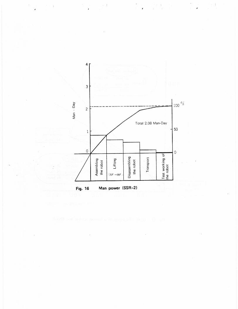
Additional to the characteristic such as higher efficiency, the SSR-2 does not need muchman power for the preparation of the spray work. Fig.16 shows the preparation man powerneeded of the SSR-2. 11.5 man-day needed for the SSR-1 preparation, but for the SSR-2only 2.08.
This shortening of the preparation time contributes to the improvement of the efficiencyof the robot system.
1
74

5.2 Quality of the spray work
According to the improvement of the stopping point precision and the rock wool feeder,the dispersion of the sprayed thickness decreased and become almost equal to the one by a humanworker's. Fig.18 shows the result of the thickness measured before finishing works.
§6. CONCLUSION
The SSR - l and SSR -2 have accomplished the initial purposes of the development of thespray robot system . But, they have not fully been developed yet. We can find many items tobe further improved . Some of the example are;
l) To make the robot operation system much easier2) To train robot operators3) To increase the capacity of the material feeder and the speed of the robot's playback
actions4) To change the teaching method from directly to remot operation using CP control or
numerical control
Recently , some people have too much expectation on the robot and robotics. But, it isalmost impossible to build up suddenly a human-less construction system with the highesttechnologies.
We have to continue the research and development of robots step by step, intending toeliminate unsafe works and improve the productivity of construction. It is true that robotics isa very powerful tool for the improvement of the construction works. Therefore engineers of theconstruction field should be familiar with robotics.
I conclude that, at this present stage , a good construction robot can not be produced
unless a lot of problems for site application overcome.
Finally, I appreciate all the advises given by engineers and experts of construction sites
and KOBELCO.
75

J
Rock Wool
Cement milk
PLANT
. at
Fig. 1 Rock wool spray system with SSR-1
Fireproofing material
76
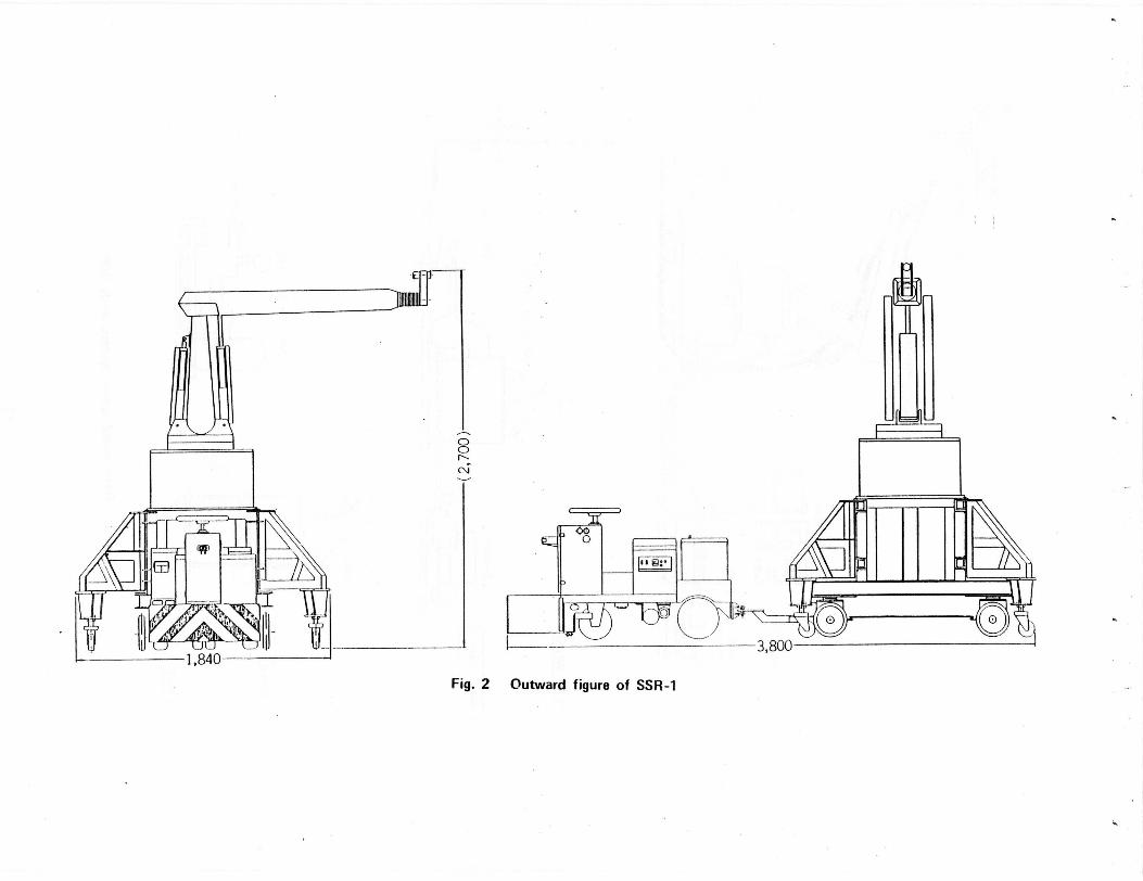
Fig. 2 Outward figure of SSR-1
I
office
floor plan (1/1,200)
I
iceoroff ice
showroomparking
parking
I
section 1 1.203
Fig. 3 Outline of Mori Building No.43

J
Hose and wire connection
I
Marking the tractor path
Putting the path wire on the floor
Putting the 80mm x 80mm plate forthe stop point on the floor
1spraying
Disassemble (partly)
Transportation to the next floor
Fig. 4 Flow diagram of the SSR-1
Carrying the robot into a building
l
(The first spraying floor only)
Programming the spray sequence
Planning the moving path
(To correspond to the beam design)
1Teaching the spraying
Planning the spray pattern
Carrying out the robot system
79

0
J
Window
Curve of window side
1,900
5001,300
165
110
Syn.
rn
8
8
88
S 8
N g
8
8
8
0
Fig. 5 Planning of the path wire
Curve of elevator shaft side
180
20 190
iDO
60
50
1,200
ro
8'
0SM
1
0
M0
1
80

2 4 6
Distance from the spray nozzle
mg /rn3
60
50
40
30
20
10
8 10 m
62.4\• Total dust
Correction positionLower stream
\ 44.6 A Upper stream
41.5 41.5
Other floor
(Spray work is not practiced)
8.546.10 5.67 5.67
2 4 6 8 10 m
Distance from the spray nozzle
Fig. 6 Dust concentration
81

1
11.5 ---------- -.; 100
10
8
° 6C
4
2
0C'C
2Ca
Fig. 7 Manpower
50
82

UCA
0
OLO
C
d
C0)
C
0)
Cl.N e
0OO o 1
COL
EC
VQ
> L0) a
C 1 E CD
>oa
a ^c
cn
0O
0_oO mN LN -
N
dc TY .OU
L yTm
n) a
NCY
OO L
0U OO
OO
U
O
0 YC. 0)
JC 0)
4)2
U 0) mC
O.0)
0)
LL
O
3)
N i
.a0)
UC
a)c
L
0.a
83

Fireproofing material
SPRAY WORK
Beam or girder
0
IOocoboon
0
000
0 Variable length (500 mm)
Traveller (Revolution: ±900)
^-'
v
Cement
milk
f^ PLANT
Mixer
0Rock wool feeder
Cement milk pump
Fig. 9 Rock wool spray system with SSR-2
Blower
I
84

1205 _ 975
1676
3400
0
2600
2200
00 0
9°
1400
Cmv)CD (Z)OCI N-I N
ITA1-4
Fig. 10 Outward figure of SSR-2
85

oa
1000 II 1000
Fig. 11 Method of the positioning
beam
86

0UN
M*
ECO
m
ECo
CD
E
CD
ECom
It
N
Q
O +00
O O> U
ECoQ)
co
C) C
^ O C
mC
L .S[
N
C
C C
CL coO ^ ^ 0(n v) a o.
N Cl
C0
ti
ECoco
8/
4
0
4
4
i
0
0
0
o C 0Q ^ 9
L a
OL - O yO E
C O L y
< O J CO
0
Co
0. 0Q)L V
U
>
E Q
0 a
ojC1
XQ
fVr
U-
Q
Q)
CoL p
C'
O
^
C
_
Q) >
Co O w ^ ^a - a

W
F-
N
- Q
Wm
L C) V
O ON N
88
a)L
C)C
lC
C.
n ^n
ON
CacmE
c
0
a)C)m
J0C)
cO
O
0)
Ea)
C7c_>
00
N
ld
V
67
E
H
>
>C.c
C
ac
OC
C.c cm
O o m U.E E E
0E
cc
c
O
a)
a`)m
cO
>
a)ma
Cm
cO
>m
a`)C)m
CO
c
JO
aP
JO n C
0aC)C
a`)
P
0a OC)
L
C)a)
LC
O
C)a)
L
C
C
0
C) a)
)
ClC
C0.
Ud
cO
a C
O
N 2 M.
N In (7 U U
C) L)
89
4
3
a0
c
2
1
0
35F--36F
0
0
a)
100 0
50
0
Fig. 16 Man power (SSR-2)
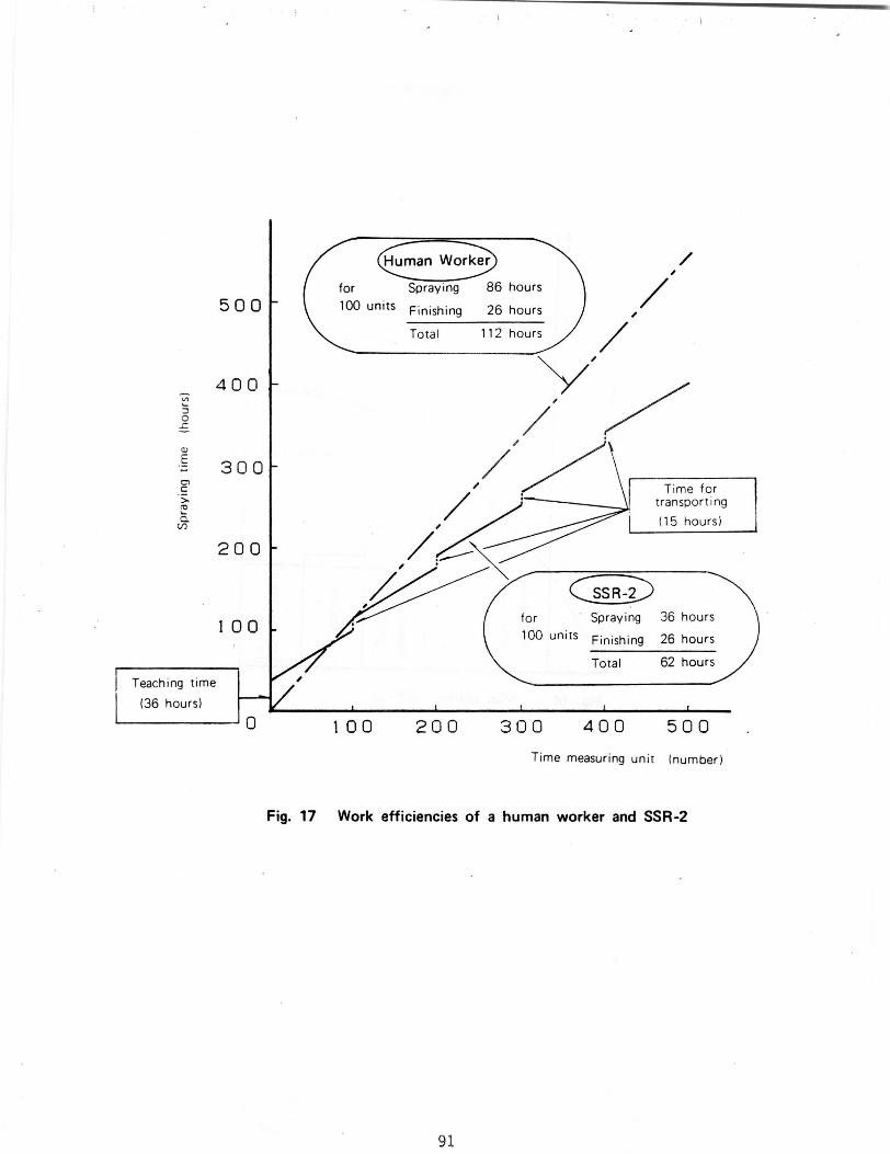
Human Worker
500for Spraying 86 hours
100 units Finishing 26 hours
Total 112 hours
400
300Time for
transporting
(15 hours)
200
100
Teaching time
(36 hours)
SS R-2
for Spraying 36 hours
100 units Finishing 26 hours
Total 62 hours
100 200 300 400 500
Time measuring unit (number)
Fig. 17 Work efficiencies of a human worker and SSR-2
91

1) Result of a skillful worker
M=96
x =53N
„/'V-=11.4%
30 45 60 75
2) Result of SSR-1
M =210 ,
z =49.2'''
,rVV=15.5N
3) Result of SSR-2
M = 200x =54.3"
/=10.0
30
Fig. 18 Thickness
III 1=I I I ^^^30 45 60 75 9u
45 60 75
92

Manipulator Tractor
Right-left turning 100°
------In-out 75°
Up-down turning 72°
Hand up-down swing 176°
Hand right - left swing 176°
Hand revolution 210°
Mobility Forward-back ( radius of gyration min. 1.2m)
SpeedArm speed Tractor speed
0 max . 1.7m/sec. max. 2 .5km/hour
Positioning precision ± 5 mm ±20 mm
Power sourceHydraulic Storage battery70kgf/cm (DC 24V)
Weight Manipulator 700 kgf
Tractor 325 kgf
Power unit 270 kgf
Control unit 200 kgf
Programmed tracting and spraying
Control functionSequential mode Electro -hydraulic servo,CP/PTP control
o Navigated by electromagnetic induction andC programable sequence controller0U Max. 128 min.
(CP mode ) Max. 63 stepsMemory capacity Max. 38000 points
(PTP mode)
Optical sensor and touch sensor for collision
Safety deviceavoidance
Automatic tractor controller(Course out , Interception collision)
Table-1 Specifications of SSR-1
93

t 9
Degree of freedom 3 itravelling revolution)
C Power hydraulic actuatoroZ Travelling speed min. 12m/min max. 6m/min
m cw Positioning precision ±5mm
c Power hydraulic actuatoro c
Revolution angle ±102.5° (manual) 1 ±900 (automatic)oQ) _ Revolution speed min. 0.4rpm, max. 2rpm
Revolution precision ±0.5°
CM Power hydraulic actuatorc c, o
Elevating speed 200inm/minC
O Elevating precision ±1 mm
Height max. 500mm
automatic travelling method programmed byControl sequence
travelling distance and revolution angle
Confirming precision ±5mmO7 cC O
U Method of correcting position Detecting the position and correcting itself
w by position sensor at the end of thev manipulator arm.
Degree of freedom 6 (Right-left turning, up-down traverse,In-out, Right-left swing, Up-down swing,Revolution)
a Position precision ±5mmc
Sequential mode Electro-hydraulic servo, CP/PTP control
Memory capacity CP: 4- 128min PTP: 3800 points
Weight 850 kg (Manipulator 335kgf Tractor 470 kgf)
Measurement Length : 1750mm
Width 1350mm
Q)sHeight : 2500 ^- 3000 mm
O
Safety function Collision protecting device with tape switch
• Optical device for detecting obstacles
• Alarm device with rotary light
Table-2 Specification of SSR-2
94

SSR-1 SSR-2
Travelling method Tractor Self-moving
Induction Electro-magnetic induction Self correcting(Controlled by computer)
Speed Max. 40m/min High 6m/minLow 1.2m/min
Revolution Radius of gyration 90°min. 1.2m
Actuator Storage battery Hydraulic actuator
Precision ±20mm ±5mm
Measurement Length 3.80m Length 1.75m
Width 1.84m Width 1.35m
Height 2.4m Height 2.5^2.9mEa^
Weight 1025 kg 805 kga Manipulator; 450 kgf Manipulator; 335 kgf
Travelling device; 250 kgf Travelling device; 470 kgf
Tractor; 325 kgf
Position control Navigated by electromagnetic Detecting the position and
induction and programable correcting itself by position
sequence controller sensor at the end of themanipulator arm
Table-3 Modification
95