Embed Size (px)
Citation preview
Development of SOFCs for Development of SOFCs for Liquid FuelsLiquid Fuels
May 5, 2009N. Fernandes, D. Schmidt,
N. Bessette
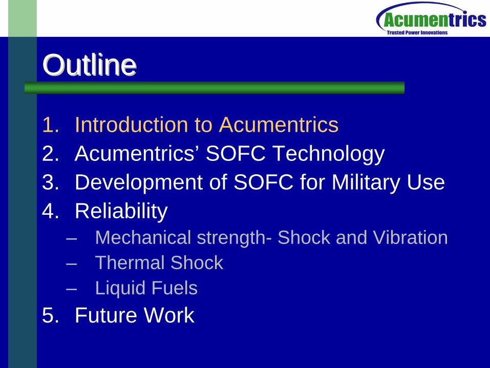
OutlineOutline
1. Introduction to Acumentrics2. Acumentrics’ SOFC Technology3. Development of SOFC for Military Use4. Reliability
– Mechanical strength- Shock and Vibration– Thermal Shock– Liquid Fuels
5. Future Work
Acumentrics Corporation• ~ 80 Employees• Manufacturing since 1994• Based in Westwood, Mass.• ~40,000 sq. ft facility• Profitable for the past 30 months• Critical disciplines in-house
Electrical EngineeringMechanical EngineeringChemical EngineeringThermal ModelingCeramics ProcessingManufacturingSales & MarketingAutomationFinance
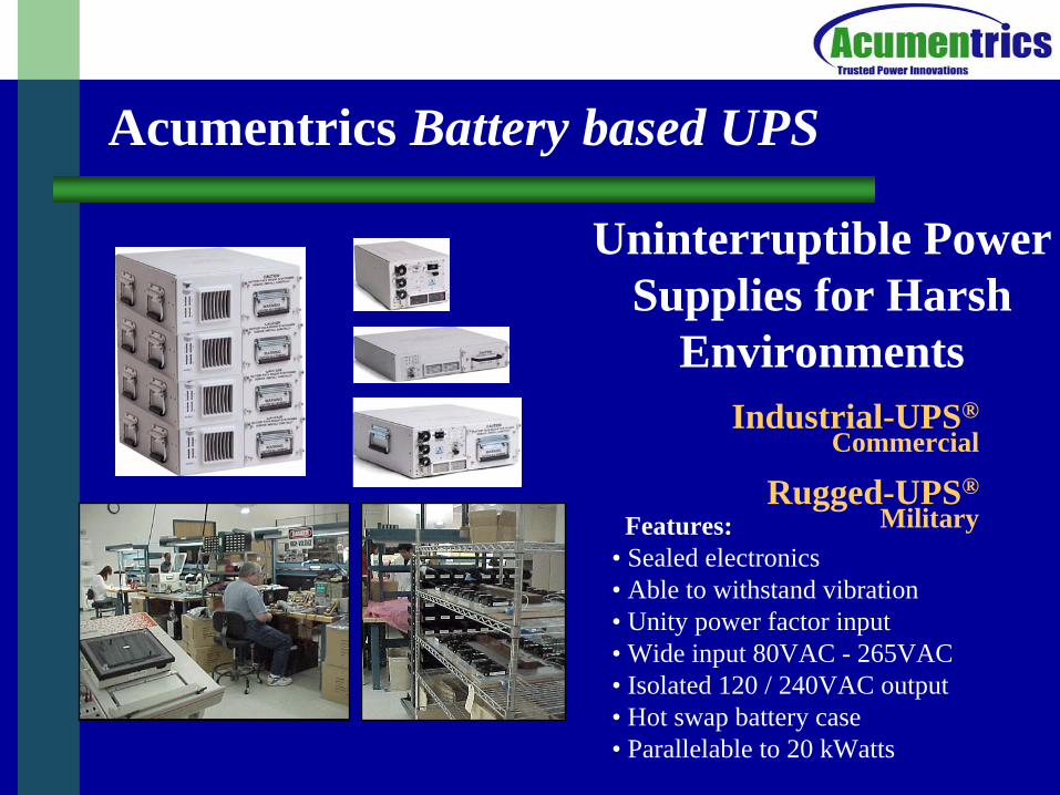
Industrial-UPS®Commercial
Rugged-UPS®Military
Acumentrics Battery based UPS
Uninterruptible Power Supplies for Harsh
Environments
Features:• Sealed electronics• Able to withstand vibration• Unity power factor input• Wide input 80VAC - 265VAC• Isolated 120 / 240VAC output• Hot swap battery case• Parallelable to 20 kWatts
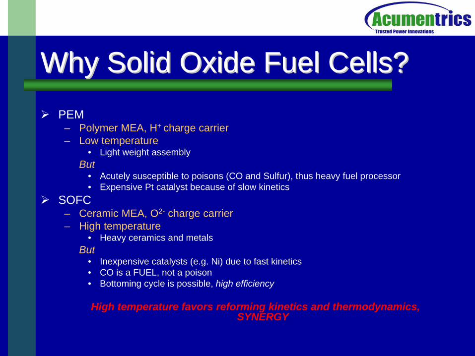
Why Solid Oxide Fuel Cells?Why Solid Oxide Fuel Cells?
PEM– Polymer MEA, H+ charge carrier– Low temperature
• Light weight assemblyBut
• Acutely susceptible to poisons (CO and Sulfur), thus heavy fuel processor• Expensive Pt catalyst because of slow kinetics
SOFC– Ceramic MEA, O2- charge carrier– High temperature
• Heavy ceramics and metalsBut
• Inexpensive catalysts (e.g. Ni) due to fast kinetics• CO is a FUEL, not a poison• Bottoming cycle is possible, high efficiency
High temperature favors reforming kinetics and thermodynamics, SYNERGY
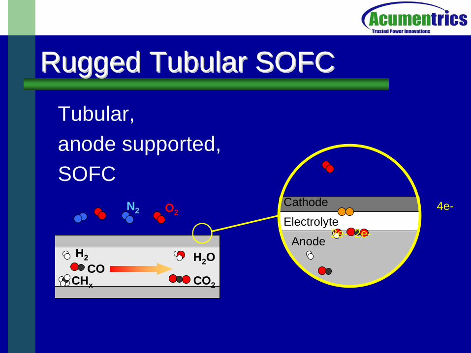
Rugged Tubular SOFC Rugged Tubular SOFC
Tubular, anode supported, SOFC
Anode
Electrolyte
Cathode 4e-
2e- 2e-
O2N2
COH2
CHx CO2
H2 O
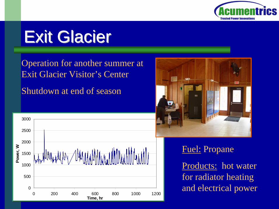
Exit GlacierExit Glacier
0
500
1000
1500
2000
2500
3000
0 200 400 600 800 1000 1200Time, hr
Pow
er, W
Operation for another summer at Exit Glacier Visitor’s Center
Shutdown at end of season
Fuel: Propane
Products: hot water for radiator heating and electrical power
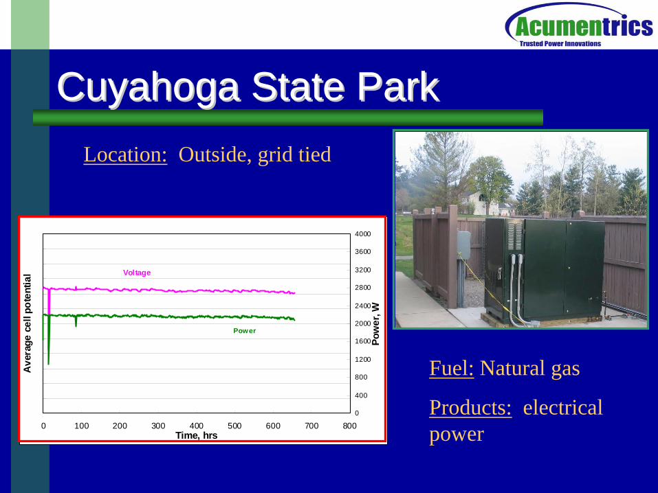
Cuyahoga State ParkCuyahoga State Park
0 100 200 300 400 500 600 700 800Time, hrs
Ave
rage
cel
l pot
entia
l
0
400
800
1200
1600
2000
2400
2800
3200
3600
4000
Pow
er, W
Voltage
Power
Fuel: Natural gas
Products: electrical power
Location: Outside, grid tied
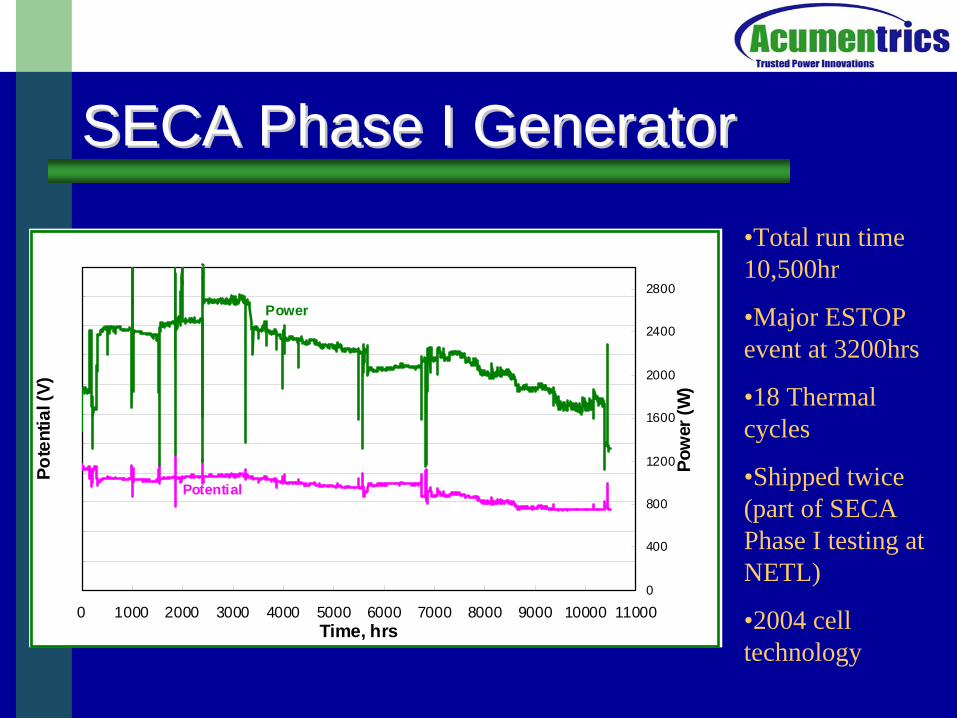
SECA Phase I GeneratorSECA Phase I Generator
0 1000 2000 3000 4000 5000 6000 7000 8000 9000 10000 11000Time, hrs
Pote
ntia
l (V)
0
400
800
1200
1600
2000
2400
2800
Pow
er (W
)
Potential
Power
•Total run time 10,500hr
•Major ESTOP event at 3200hrs
•18 Thermal cycles
•Shipped twice (part of SECA Phase I testing at NETL)
•2004 cell technology
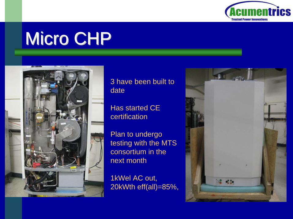
Micro CHPMicro CHP
3 have been built to date
Has started CE certification
Plan to undergo testing with the MTS consortium in the next month
1kWel AC out, 20kWth eff(all)=85%,
SOFC for Military ApplicationsSOFC for Military ApplicationsHigh Performance
– High power density, small and light– Silent– Rapid start-up– Efficient, water neutral
Reliable– Mechanical, shock and vibration– Thermal, shock and thermal cycling– Electrical, load cycling– Chemical, poison (sulfur) and fouling (carbon) resistance
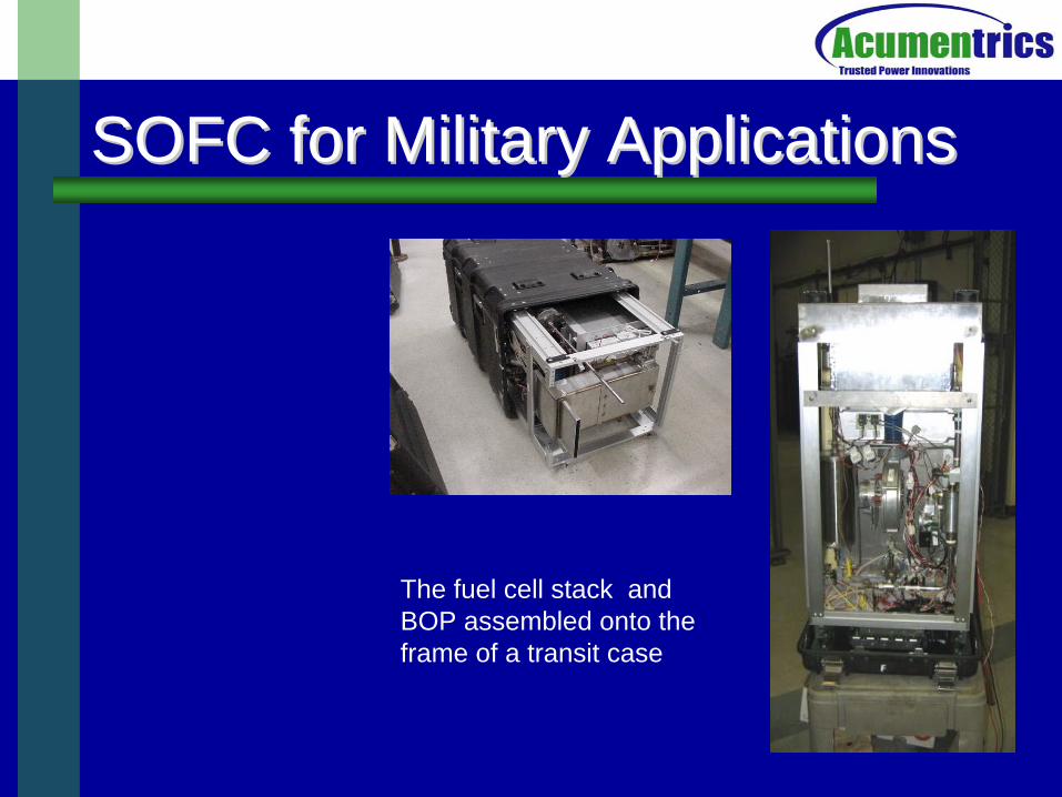
SOFC for Military ApplicationsSOFC for Military Applications
The fuel cell stack and BOP assembled onto the frame of a transit case
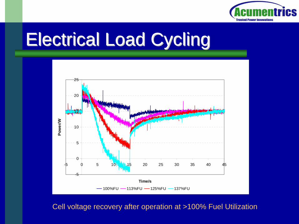
Electrical Load CyclingElectrical Load Cycling
-5
0
5
10
15
20
25
-5 0 5 10 15 20 25 30 35 40 45
Time/s
Pow
er/W
100%FU 113%FU 125%FU 137%FU
Cell voltage recovery after operation at >100% Fuel Utilization
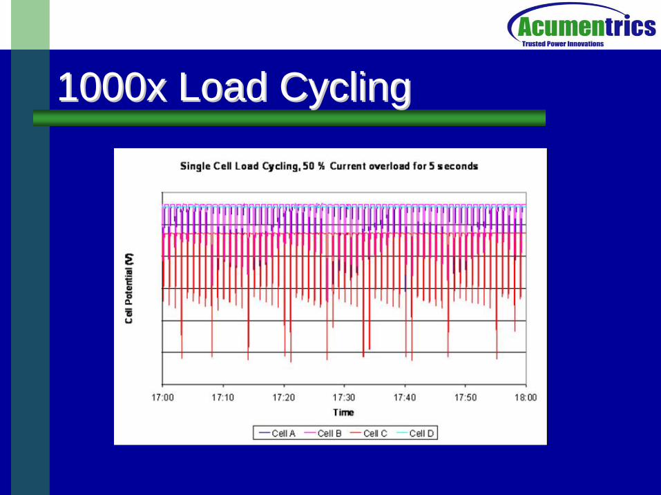
1000x Load Cycling 1000x Load Cycling
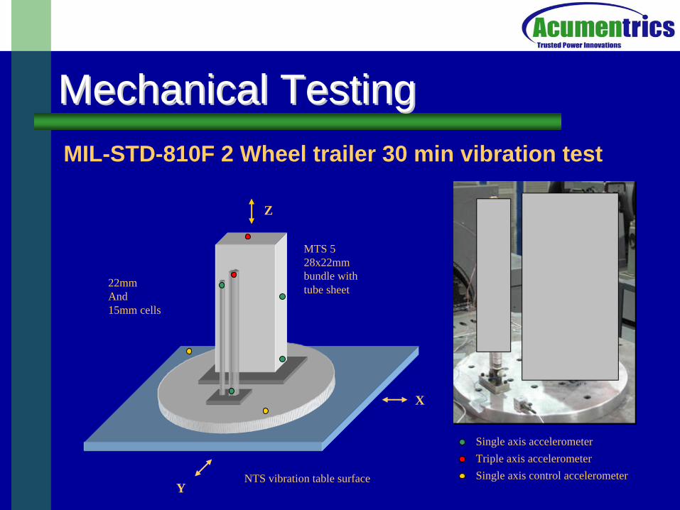
Mechanical TestingMechanical Testing
MTS 5 28x22mm bundle with tube sheet
NTS vibration table surface
Single axis accelerometerTriple axis accelerometerSingle axis control accelerometer
Z
X
Y
22mmAnd15mm cells
MIL-STD-810F 2 Wheel trailer 30 min vibration test
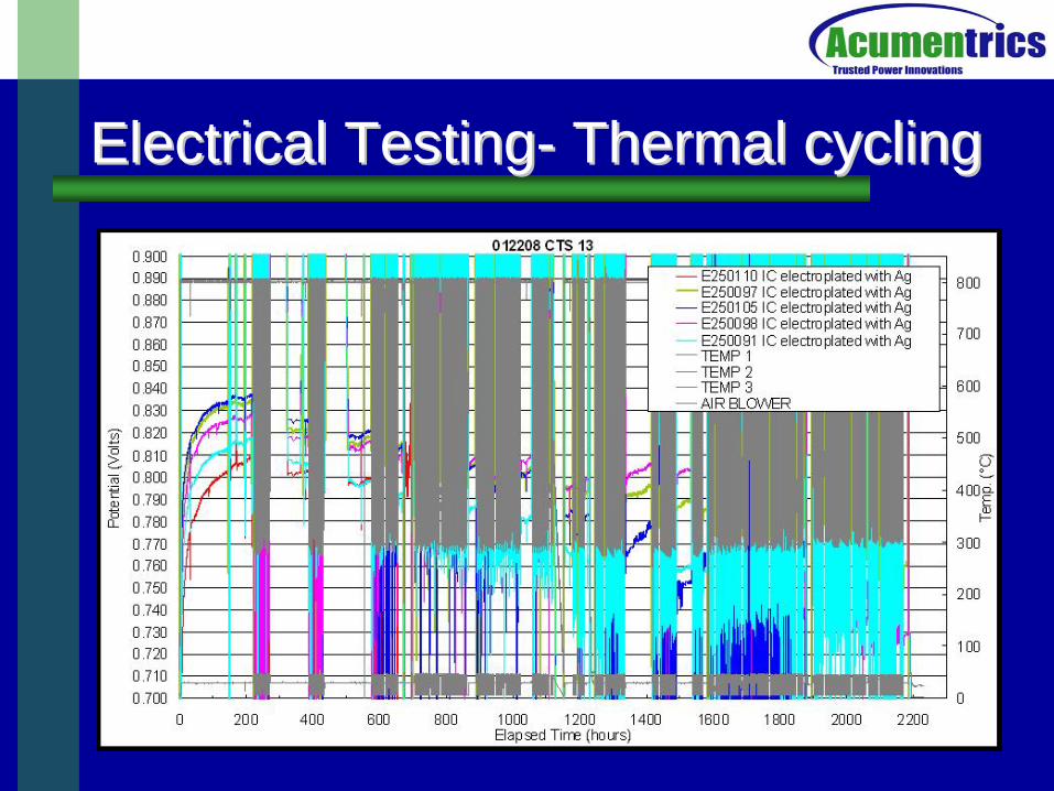
Electrical TestingElectrical Testing-- Thermal cyclingThermal cycling
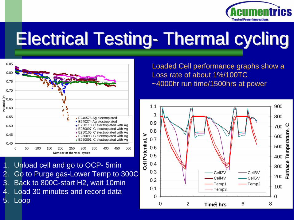
Electrical TestingElectrical Testing-- Thermal cyclingThermal cycling
0.40
0.45
0.50
0.55
0.60
0.65
0.70
0.75
0.80
0.85
0 50 100 150 200 250 300 350 400 450 500Number of thermal cycles
Pote
ntia
l (V)
E240576 Ag electroplatedE240274 Ag electroplatedE250110 IC electroplated with AgE250097 IC electroplated with AgE250105 IC electroplated with AgE250098 IC electroplated with AgE250091 IC electroplated with Ag
00.10.20.30.40.50.60.70.80.9
11.1
0 2 4 6 8Time, hrs
Cell
Pote
ntia
l, V
0
100
200
300
400
500
600
700
800
900
Furn
ace
Tem
pera
ture
, C
Cell2V Cell3VCell4V Cell5VTemp1 Temp2Temp3
1. Unload cell and go to OCP- 5min2. Go to Purge gas-Lower Temp to 300C3. Back to 800C-start H2, wait 10min4. Load 30 minutes and record data5. Loop
Loaded Cell performance graphs show aLoss rate of about 1%/100TC~4000hr run time/1500hrs at power
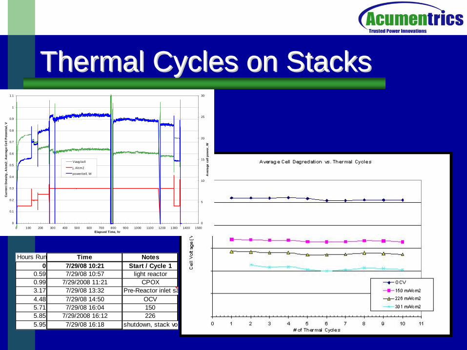
Thermal Cycles on StacksThermal Cycles on Stacks
Hours Run Time Notes0 7/29/08 10:21 Start / Cycle 1
0.59 7/29/08 10:57 light reactor0.99 7/29/2008 11:21 CPOX3.17 7/29/08 13:32 Pre-Reactor inlet sa4.48 7/29/08 14:50 OCV5.71 7/29/08 16:04 1505.85 7/29/2008 16:12 2265.95 7/29/08 16:18 shutdown, stack vol
0
0.1
0.2
0.3
0.4
0.5
0.6
0.7
0.8
0.9
1
1.1
0 100 200 300 400 500 600 700 800 900 1000 1100 1200 1300 1400 1500Elapsed Time, hr
Cur
ren
t Dne
sity
, A/c
m2;
Ave
rag
e C
ell P
oten
tial,
V
0
5
10
15
20
25
30
Ave
rage
cel
l pow
er, W
Vavg/cell
j, A/cm2
power/cell, W
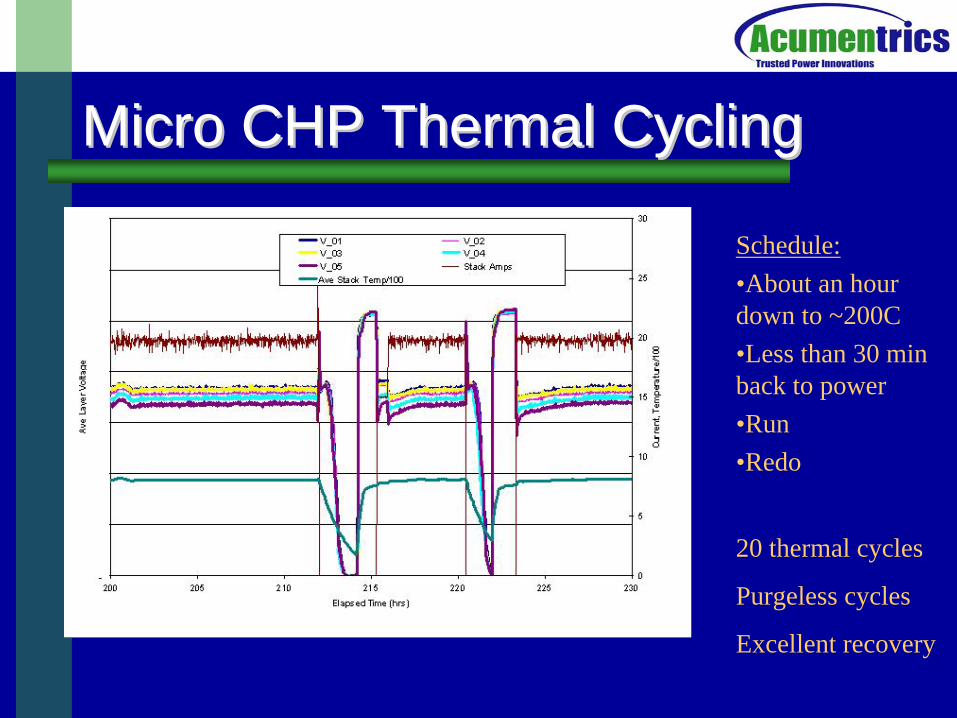
Micro CHP Thermal CyclingMicro CHP Thermal Cycling
Schedule:•About an hour down to ~200C•Less than 30 min back to power•Run•Redo
20 thermal cycles
Purgeless cycles
Excellent recovery
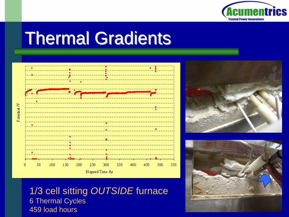
Thermal GradientsThermal Gradients
1/3 cell sitting OUTSIDE furnace6 Thermal Cycles459 load hours
Fuel FlexibilityFuel Flexibility
High energy density fuels
JP-8 MIL-T-83133– Aromatics 15-20%– Olefins 1-2%– Saturates 78-83%– Sulfur 10-1000ppm
Synthetic JP-8 – Saturates 100%– Sulfur < 0.1ppm
LPG– Sulfur up to 180 ppm
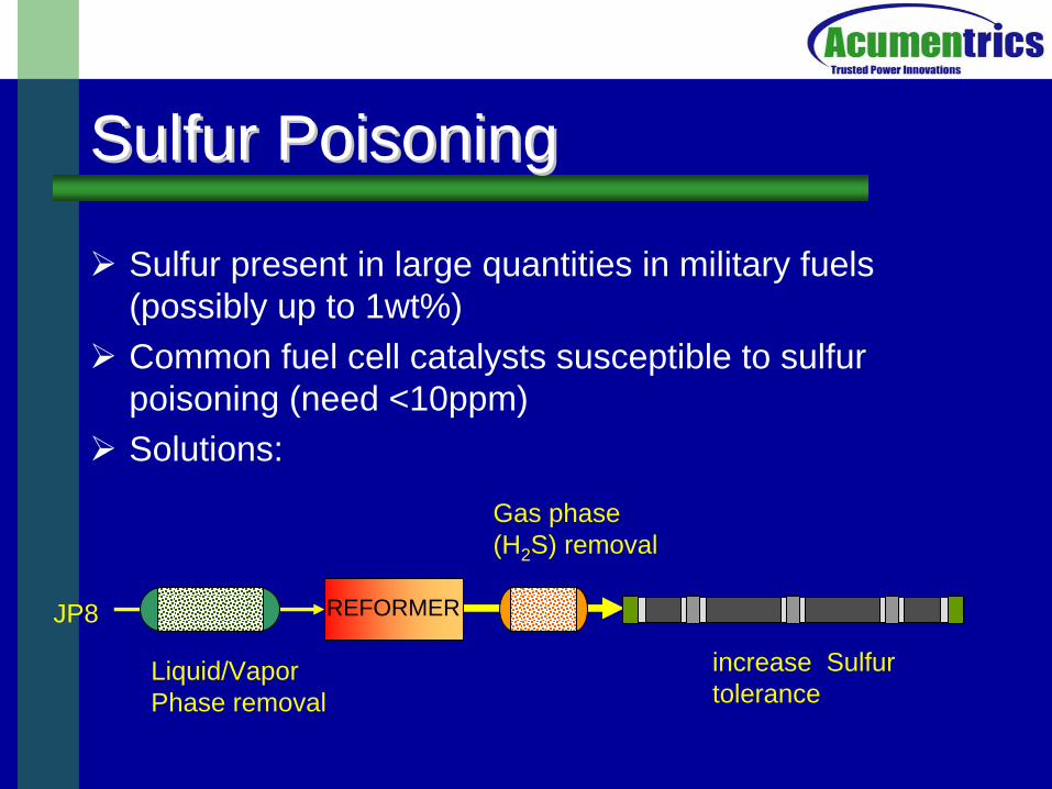
Sulfur PoisoningSulfur Poisoning
Sulfur present in large quantities in military fuels (possibly up to 1wt%)
Common fuel cell catalysts susceptible to sulfur poisoning (need <10ppm)
Solutions:
Liquid/Vapor Phase removal
Gas phase(H2 S) removal
REFORMER
increase Sulfurtolerance
JP8
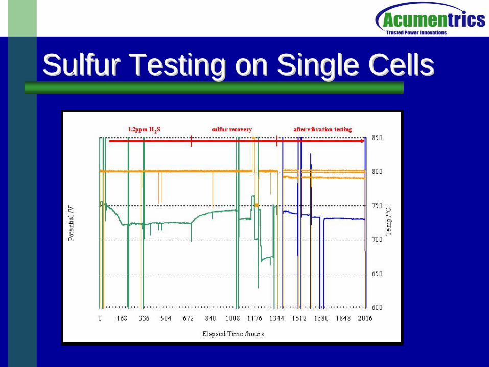
Sulfur Testing on Single CellsSulfur Testing on Single Cells

JP8 ReformingJP8 ReformingReforming Modes
– Steam reforming (H2 O, CHx )• High efficiencies, requires significant water (high S/C), heat
transfer difficulties, larger reactors, upstream liquid phase desulfurization
– Partial oxidation (O2 ,CHx )• Less efficient, but small reactors and fast dynamics, down stream
gas phase desulfurization
– Autothermal reforming (O2 , H2 O, CHx )• Best (and worst) of both worlds?
Reforming Techniques– Catalytic, Plasma, Thermal
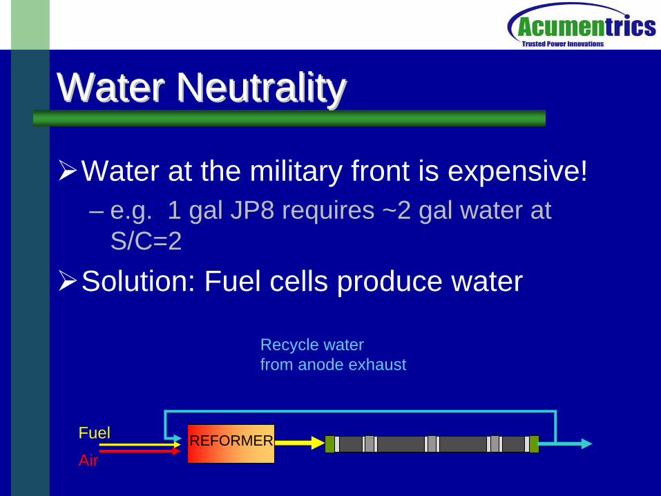
Water NeutralityWater Neutrality
Water at the military front is expensive!– e.g. 1 gal JP8 requires ~2 gal water at
S/C=2Solution: Fuel cells produce water
Recycle water from anode exhaust
REFORMERAir
Fuel
Catalytic Reforming at AcumentricsCatalytic Reforming at Acumentrics
Breadboard testing of reformersSteam Reforming
– >1000hr testing on S-8 (zero sulfur) S/C=4– 300W stack test
Partial Oxidation – JP-8 (~280ppmS) CPOX reformer at steady state– 24 hr test on 1kW stack
ATR– ATR reformer– 1000hr testing on JP8 (~10 ppmS) on a 1kW stack– 2 days of transient testing, load following and cycling
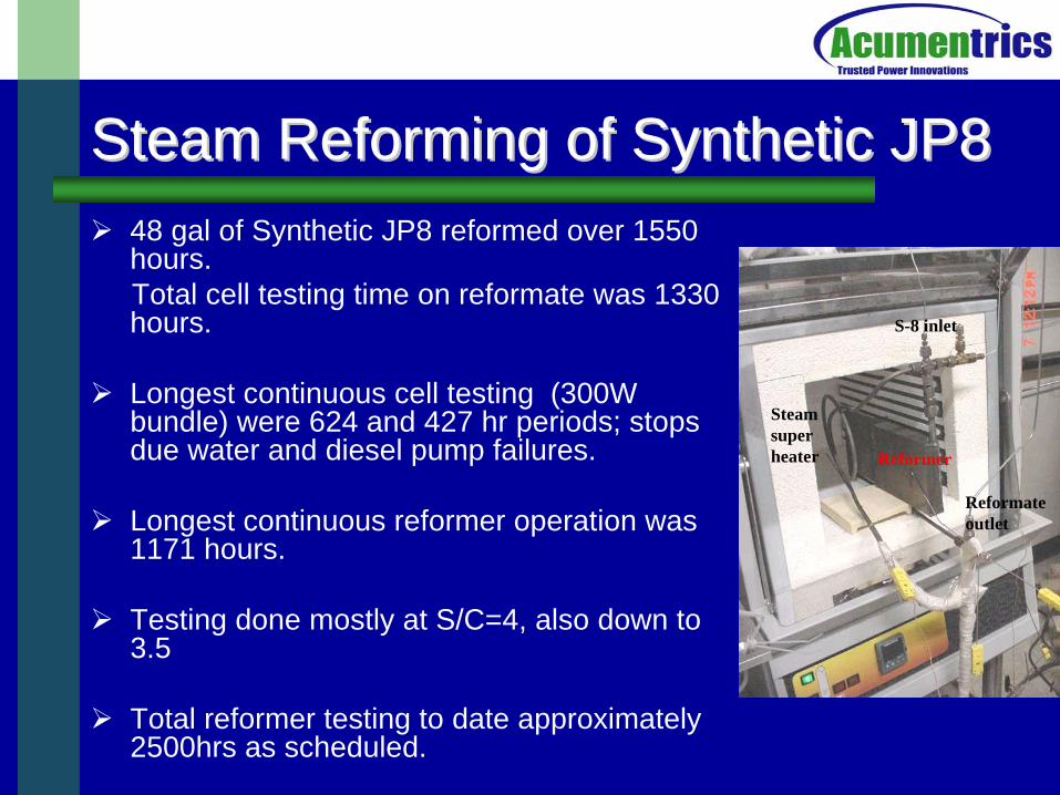
Steam Reforming of Synthetic JP8Steam Reforming of Synthetic JP8
48 gal of Synthetic JP8 reformed over 1550 hours. Total cell testing time on reformate was 1330 hours.
Longest continuous cell testing (300W bundle) were 624 and 427 hr periods; stops due water and diesel pump failures.
Longest continuous reformer operation was 1171 hours.
Testing done mostly at S/C=4, also down to 3.5
Total reformer testing to date approximately 2500hrs as scheduled.
Water pre heater/boil er
S-8 fuel
Reformer
Steam super heater
S-8 inlet
Reformate outlet
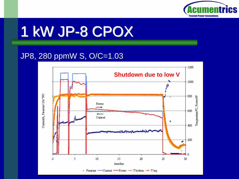
1 kW JP1 kW JP--8 CPOX8 CPOXJP8, 280 ppmW S, O/C=1.03
Shutdown due to low V
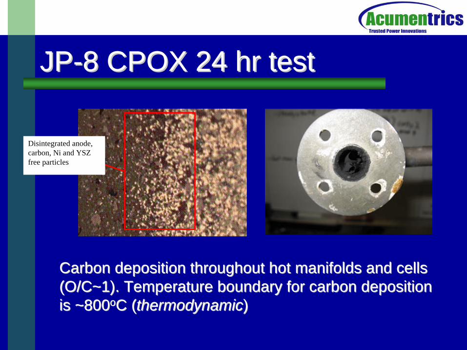
JPJP--8 CPOX 24 hr test8 CPOX 24 hr test
Disintegrated anode, carbon, Ni and YSZ free particles
Carbon deposition throughout hot manifolds and cells Carbon deposition throughout hot manifolds and cells (O/C~1). Temperature boundary for carbon deposition (O/C~1). Temperature boundary for carbon deposition is ~800is ~800ooC (C (thermodynamicthermodynamic))
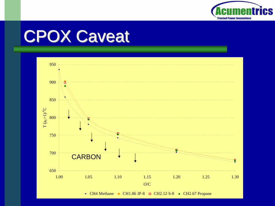
650
700
750
800
850
900
950
1.00 1.05 1.10 1.15 1.20 1.25 1.30
O/C
T (a
C>1
)/o C
CH4 Methane CH1.86 JP-8 CH2.12 S-8 CH2.67 Propane
CPOX CaveatCPOX Caveat
CARBON
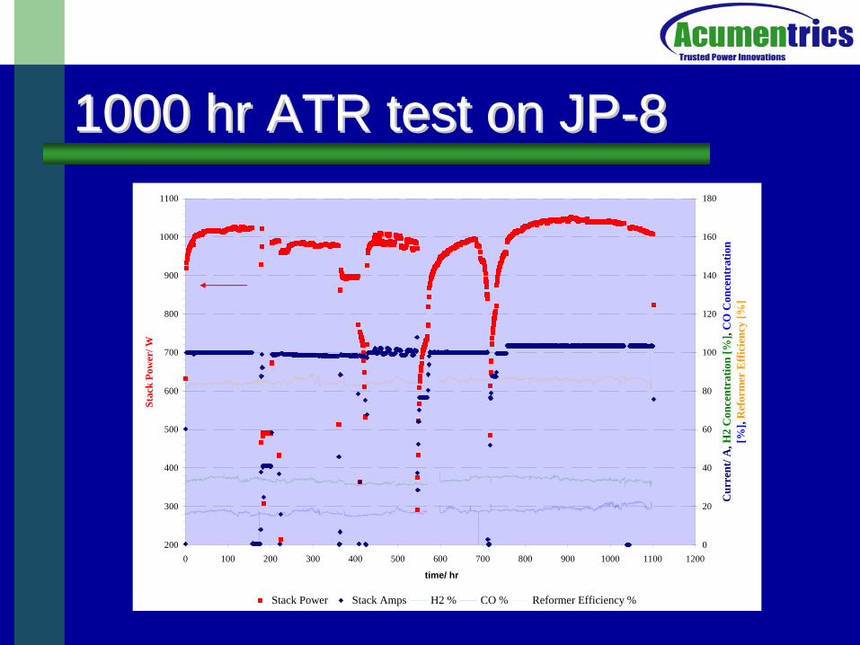
1000 hr ATR test on JP1000 hr ATR test on JP--88
200
300
400
500
600
700
800
900
1000
1100
0 100 200 300 400 500 600 700 800 900 1000 1100 1200
time/ hr
Stac
k Po
wer
/ W
0
20
40
60
80
100
120
140
160
180
Cur
rent
/ A, H
2 C
once
ntra
tion
[%],
CO
Con
cent
ratio
n [%
], R
efor
mer
Eff
icie
ncy
[%]
Stack Power Stack Amps H2 % CO % Reformer Efficiency %
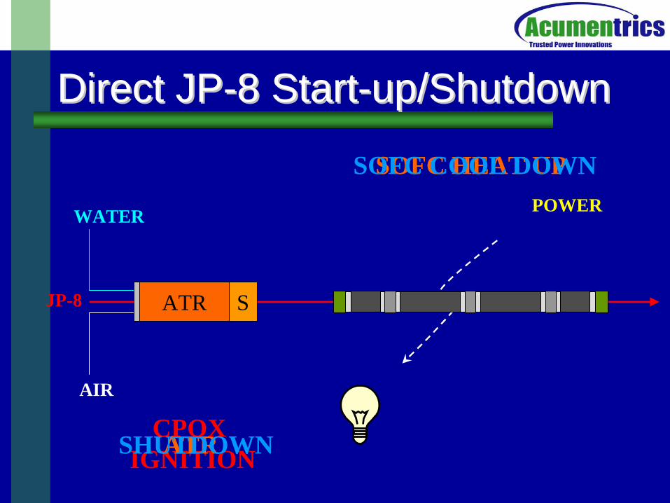
Direct JPDirect JP--8 Start8 Start--up/Shutdownup/Shutdown
SCPOXATR
AIR
WATER
JP-8
POWER
SOFC HEAT UP
CPOX IGNITIONATR
SOFC COOL DOWN
SHUTDOWN
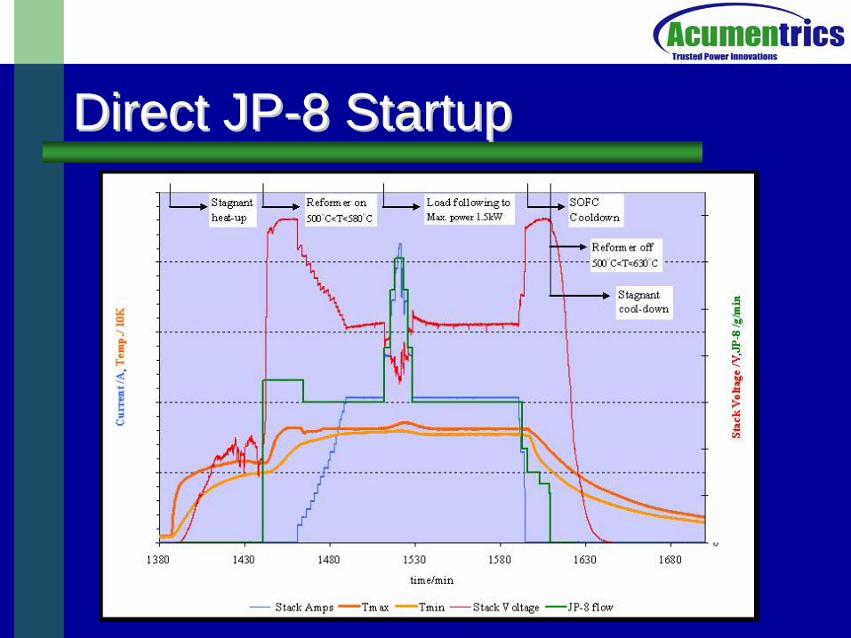
Direct JPDirect JP--8 Startup8 Startup
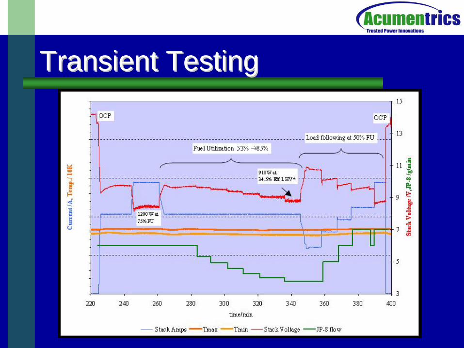
Transient TestingTransient Testing
Going ForwardGoing Forward
Integration of SOFC stack with ATR reformer– SOFC controls ATR, enabling transient
testing (fast start-up, load following, thermal cycling)
– Incremental integration to full water neutrality
Continued testing of reformers
Thanks toThanks to
Reginald Tyler of EEREDon Hoffman, John Kuseian, John
Heinzel of ONRMTS/Consortium membersAcumentrics Team