Embed Size (px)
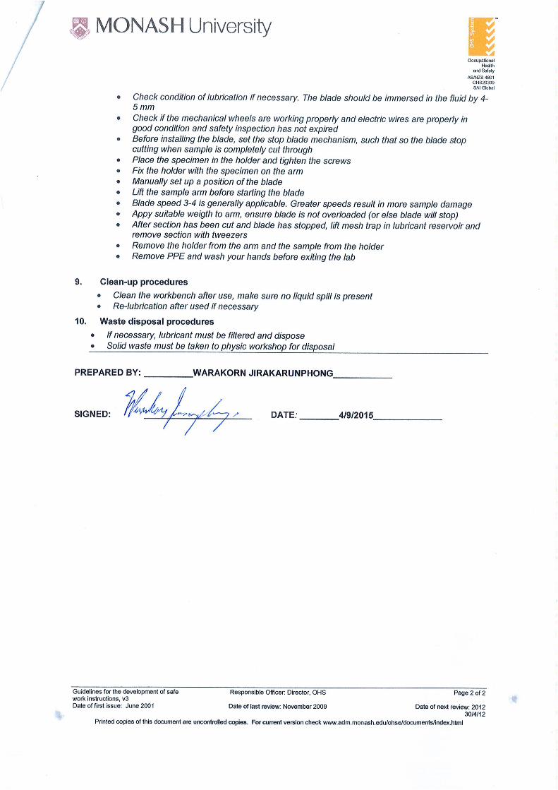
Citation preview
DEVELOPMENT OF NOVEL DENTAL METALLIC IMPLANT Ti-14%wtZr
ALLOY Investigation of mechanical properties and fracture surface
By Warakorn Jirakarunphong
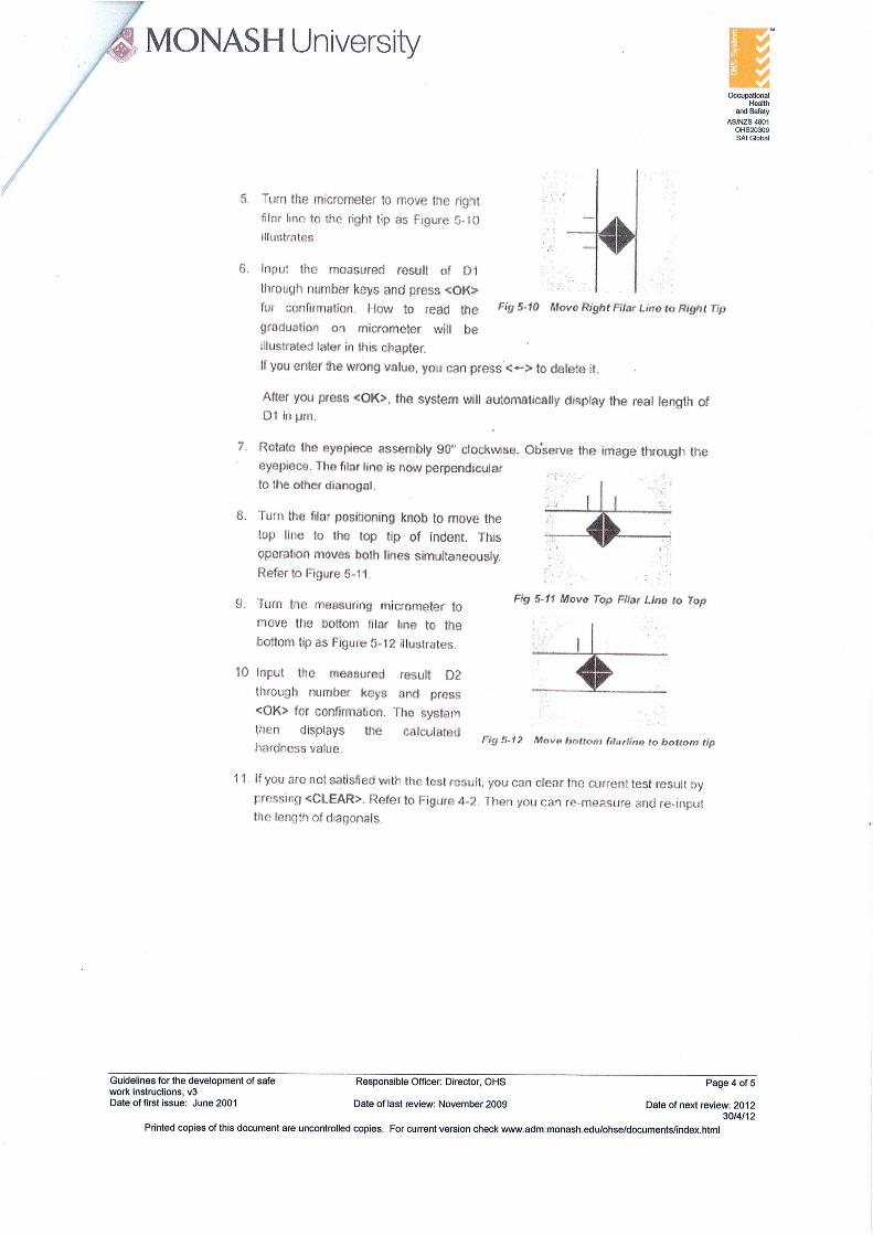
Student ID: 23736569
Supervisors:
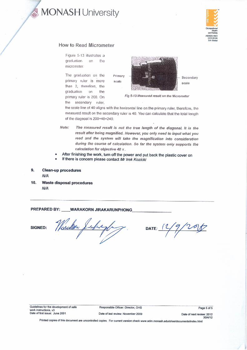
Dr.Andrey Molotnikov and A/Prof. Rimma Lapovok (Deakin University)
OCTOBER 30, 2015
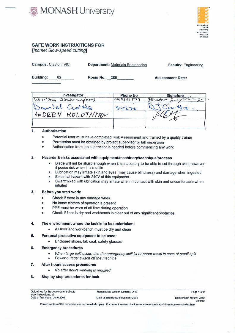
MONASH UNIVERSITY AUSTRALIA
1
Table of Contents
Abstract ................................................................................................................................ 2
1. Introduction ...................................................................................................................... 3
2. Literature review ............................................................................................................... 4
3. Objectives of this research project ..................................................................................... 8
4. Methodology/Experimental techniques ............................................................................. 9
5. Material Specification ...................................................................................................... 11
I. Results and Discussion ...................................................................................................... 12
6. Optical microstructure revelation of Ti-14wt%Zr alloy ...................................................... 12
7. SEM imaging of the As-received Ti-14%Zr alloy ................................................................. 13
8. Investigation on whether different can material used during ECAP processing will affect
microstructure of ECAP processed Ti-14%wtZr in cross-sectional and longitudinal direction . 15
9. Comparing how different can material affect the microstructure of ECAPed Ti-14%wtZr
alloy .................................................................................................................................... 23
10. Investigation on the mechanical properties of As-Received Ti-14%Zr alloy ...................... 24
11. Mechanical properties of ECAPed Ti-14%wt Zr alloy using different can material and
processing temperature....................................................................................................... 28
12. Tensile facture surface analysis of As-received and 4 ECAP Passes at temperature of 500C
and 400C with varying in can-aided ECAP material of Titanium Zirconium alloys .................. 30
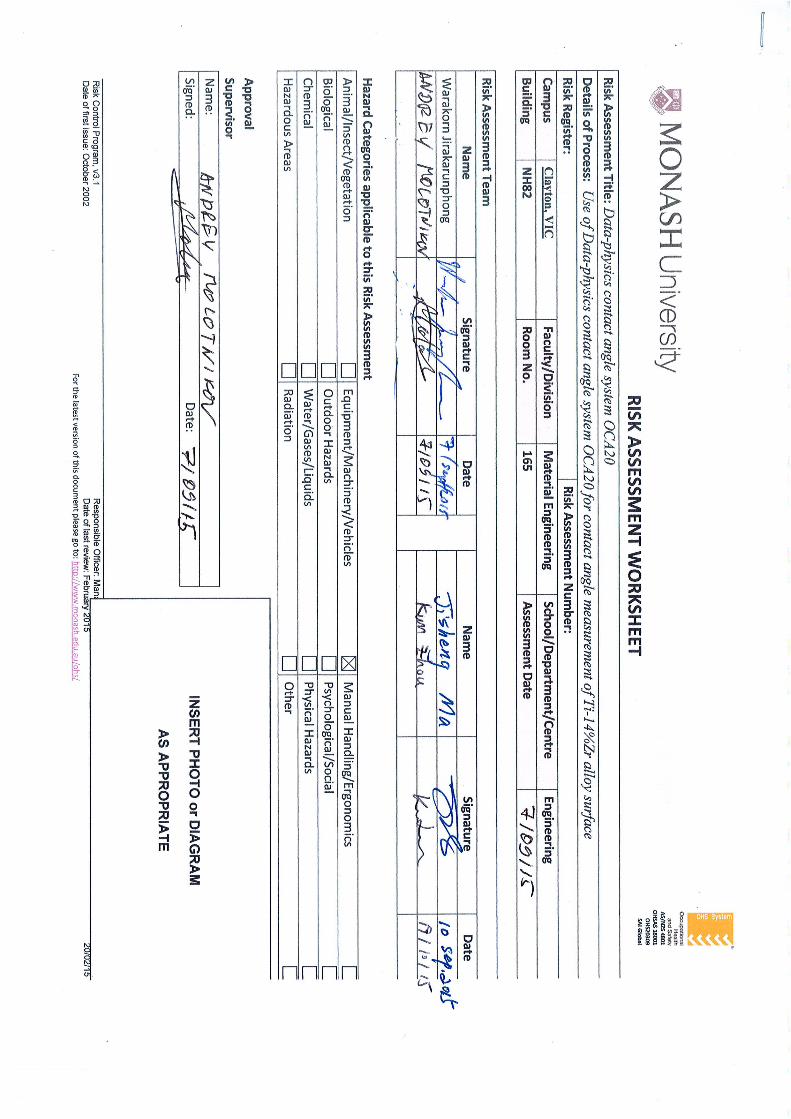
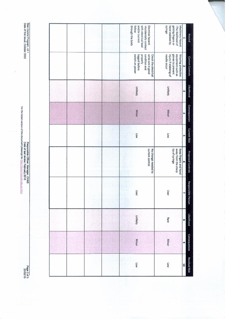
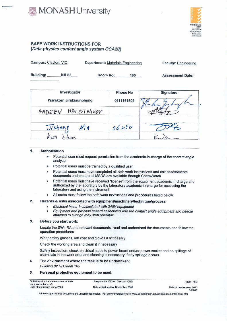
13. Contact angle measurement via OCA20 Physics machine ................................................ 36
14. Transmission electron microscopy (TEM) imaging of As-received Ti-14%wtZr and ECAPed-
Ti-14%wtZr .......................................................................................................................... 37
15. Conclusion of the finding ............................................................................................... 39
16. Recommendation for future work and Evaluation of the project .................................... 42
17. Acknowledgement ......................................................................................................... 43
18. References ..................................................................................................................... 43
2
Abstract
The increasing growth in aging population in Australia and developed countries, results in an
increasing demand biomedical implants. The implants must survive a severe environment in
human body, while withstanding high mechanical loads. This research project is focusing on
developing novel dental implant material, alloy of Titanium and Zirconium. This alloy has
already demonstrated superiority in term of its mechanical strengths, corrosion resistance
compared to commercial pure titanium while maintaining its biocompatibility and
osseointegration. The mechanical strength of novel dental Ti-Zr alloy can be further improved
by use of severe plastic deformation technique, termed “Equal Channel Angular Pressing”. ECAP
process reduced the grain size of the material to sub-micron range and therefore increases the
strength of Ti-Zr alloy which will allow to further reduce the implant diameter. Smaller diameter
implants are less invasive to the body and inflict less pain. The main goal for this project is to
find optimal (lowest as possible) processing ECAP temperature, to obtain high strength ultra-
fined grained Ti-Zr alloy, which will be beneficial in terms of production cost and affordability.
3
1. Introduction
In the current world situation where there is a trend toward the increasing in ageing
population, the elder population have an increasing risk in hard tissue failure, to solve this
problem and to improve the quality of life, this leads to the increasing in the demand for
biometallic implants, however current biomatallic materials require improvement in term of its
biofunctionality and biocompatibility[1]. Subsequently, the development in novel biomateriallic
material has begun, which is Titanium-Zirconium alloys as oppose to current commercially
available biometallic implants such as stainless steel, Co-Cr alloys and Ti-6Al-4V alloys due to its
lower in biocompatibility and toxicity from its alloying elements for instances Ni and V are toxic
and Al causes Alzheimer’s disease [1] [2], mainly used in the treatment of partially or fully
edentulous patients [2]. The Ti-Zr alloys show, in according to previous studies, its
biocompatibility and osseointergration as good as pure titanium with matching strength and
corrosion resistance of Ti-6Al-4V. [2]
In particular for dental application, the implant has to be produced in small diameter, it has
been confirmed by the current literature that TiZr alloys has strength up to 40% higher than
conventional grade IV titanium implant.[2] In the case of single tooth implant, where small
diameter of less than 3.5mm (≤3.5mm) are preferable, the mechanical/tensile strength of CP-Ti
is not sufficient and reducing in the diameter of CP-Ti will increase the risk of fatigue failure. [2]
To enhance the strength of Ti-Zr alloys further, in order to create smaller implant, the ECAP or
Equal Channel Angular pressing has been employed to modify the microstructure of Ti-Zr alloy
to ultrafine grain size and by referring to Hall-Petch relationship, the smaller the grain size is the
higher the yield strength and hence its hardness.
To improve further in osseointragration of Ti-Zr alloys, the SLA or SLAactive surface treatment
can be employed and this will only be suitable for alpha-phase (α) Ti-Zr alloys (Roxolid Institut
Straumann AG,Basel,Switzerland)[2].

4
2. Literature review
This section will outline the literature studies related to the scope of this project. The project
will focus on solely to find the optimal processing temperature of (alpha phase) Ti-14%wtZr (for
further SLA and SLActive treatment) during ECAP analyzing the obtained and how it affects its
microstructure and subsequently its mechanical properties.
2.1 Titanium alloys as biometallic implant and Zirconium as an alloying element
Ti alloys exhibits the highest biocompatibility, corrosion resistance and specific strength (ratio
of the tensile strength to density) in comparison to stainless steel and Co-Cr alloy. The Ti alloys
are therefore an attractive choice as a biomatallic implant to replace hard tissues (bone). The
high young modulus is associated with stress shielding effect, in which stress is inhomogenously
transferred more toward the implant than the bone, due to high elastic modulus of implant.
This causes bone absorption and loosening of implant or re-fracture of the bone after removal
of the implant. [3]
The zirconium is added to titanium because, it belongs to the same group as titanium and it is a
neutral element in solid solution with Ti and it does not affect the beta-Ti phase transformation
temperature. Zr has high solubility in both crystalline phase of alpha and beta Ti. Zr as a
substitution element, it causes the hardening of the alloy, increase corrosion resistance and
improve biocompatibility. [4]
2.2 Biocompatibility of Ti-Zr alloy for the use in endosseous dental implant
Ti Zr alloy is found experimentally to be as good as pure titanium in term of its biocompatibility
and osseointregration and corrosion resistance. With the Zr alloying element on the Ti, Ti-Zr
alloy can be produced with smaller diameter with a strength higher than the conventional cold-
worked grade IV titanium implant. The TiZr alloy with small diameter implant can have strength
up to 40% higher than the conventional cold-worked pure titanium. The smaller the diameter of
the implant is associated with the increasing in the risk of fatigue failure for pure Ti dental
implant. [5]
The Ti-Zr alloy is retaining alpha crystal structure system, which is the same crystal structure as
the CP-Titanium. The alpha structure of the TiZr alloy ensures the SLA and SLActive surface
treatment is compatible with the TiZr alloy for enchantment of osseointegration. The TiZr has
high successful implantation rate around 95.2% to 100% in human and can be use in high
loading situation. [5]
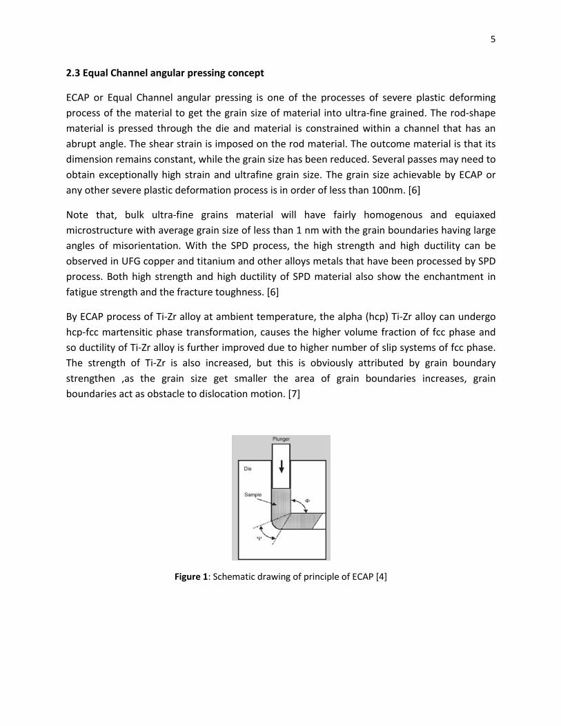
2.3 Equal Channel angular pressing concept
ECAP or Equal Channel angular pressing is one of the processes of severe plastic deforming
process of the material to get the grain size of material into ultra
material is pressed through the die and material is constrained within a channel that has an
abrupt angle. The shear strain is imposed on the rod material. The outcome mate
dimension remains constant, while the grain size has been reduced. Several passes may need to
obtain exceptionally high strain and ultrafine grain size. The grain size achievable by ECAP or
any other severe plastic deformation process is i
Note that, bulk ultra-fine grains material will have fairly homogenous and equiaxed
microstructure with average grain size of less than 1 nm with the grain boundaries having large
angles of misorientation. With the SPD proce
observed in UFG copper and titanium and other alloys metals that have been processed by SPD
process. Both high strength and high ductility of SPD material also show the enchantment in
fatigue strength and the fracture toughness. [
By ECAP process of Ti-Zr alloy at ambient temperature, the alpha (hcp) Ti
hcp-fcc martensitic phase transformation, causes the higher volume fraction of fcc phase and
so ductility of Ti-Zr alloy is further impr
The strength of Ti-Zr is also increased, but this is obviously attributed by grain boundary
strengthen ,as the grain size get smaller the area of grain boundaries increases, grain
boundaries act as obstacle to dislocation motion. [
Figure 1: Schematic drawing of principle of ECAP
Equal Channel angular pressing concept
ECAP or Equal Channel angular pressing is one of the processes of severe plastic deforming
e material to get the grain size of material into ultra-fine grained. The rod
material is pressed through the die and material is constrained within a channel that has an
abrupt angle. The shear strain is imposed on the rod material. The outcome mate
dimension remains constant, while the grain size has been reduced. Several passes may need to
obtain exceptionally high strain and ultrafine grain size. The grain size achievable by ECAP or
any other severe plastic deformation process is in order of less than 100nm. [6]
fine grains material will have fairly homogenous and equiaxed
microstructure with average grain size of less than 1 nm with the grain boundaries having large
angles of misorientation. With the SPD process, the high strength and high ductility can be
observed in UFG copper and titanium and other alloys metals that have been processed by SPD
process. Both high strength and high ductility of SPD material also show the enchantment in
fracture toughness. [6]
Zr alloy at ambient temperature, the alpha (hcp) Ti-Zr alloy can undergo
fcc martensitic phase transformation, causes the higher volume fraction of fcc phase and
Zr alloy is further improved due to higher number of slip systems of fcc phase.
Zr is also increased, but this is obviously attributed by grain boundary
strengthen ,as the grain size get smaller the area of grain boundaries increases, grain
stacle to dislocation motion. [7]
: Schematic drawing of principle of ECAP [4]
5
ECAP or Equal Channel angular pressing is one of the processes of severe plastic deforming
fine grained. The rod-shape
material is pressed through the die and material is constrained within a channel that has an
abrupt angle. The shear strain is imposed on the rod material. The outcome material is that its
dimension remains constant, while the grain size has been reduced. Several passes may need to
obtain exceptionally high strain and ultrafine grain size. The grain size achievable by ECAP or
]
fine grains material will have fairly homogenous and equiaxed
microstructure with average grain size of less than 1 nm with the grain boundaries having large
ss, the high strength and high ductility can be
observed in UFG copper and titanium and other alloys metals that have been processed by SPD
process. Both high strength and high ductility of SPD material also show the enchantment in
Zr alloy can undergo
fcc martensitic phase transformation, causes the higher volume fraction of fcc phase and
oved due to higher number of slip systems of fcc phase.
Zr is also increased, but this is obviously attributed by grain boundary
strengthen ,as the grain size get smaller the area of grain boundaries increases, grain
6
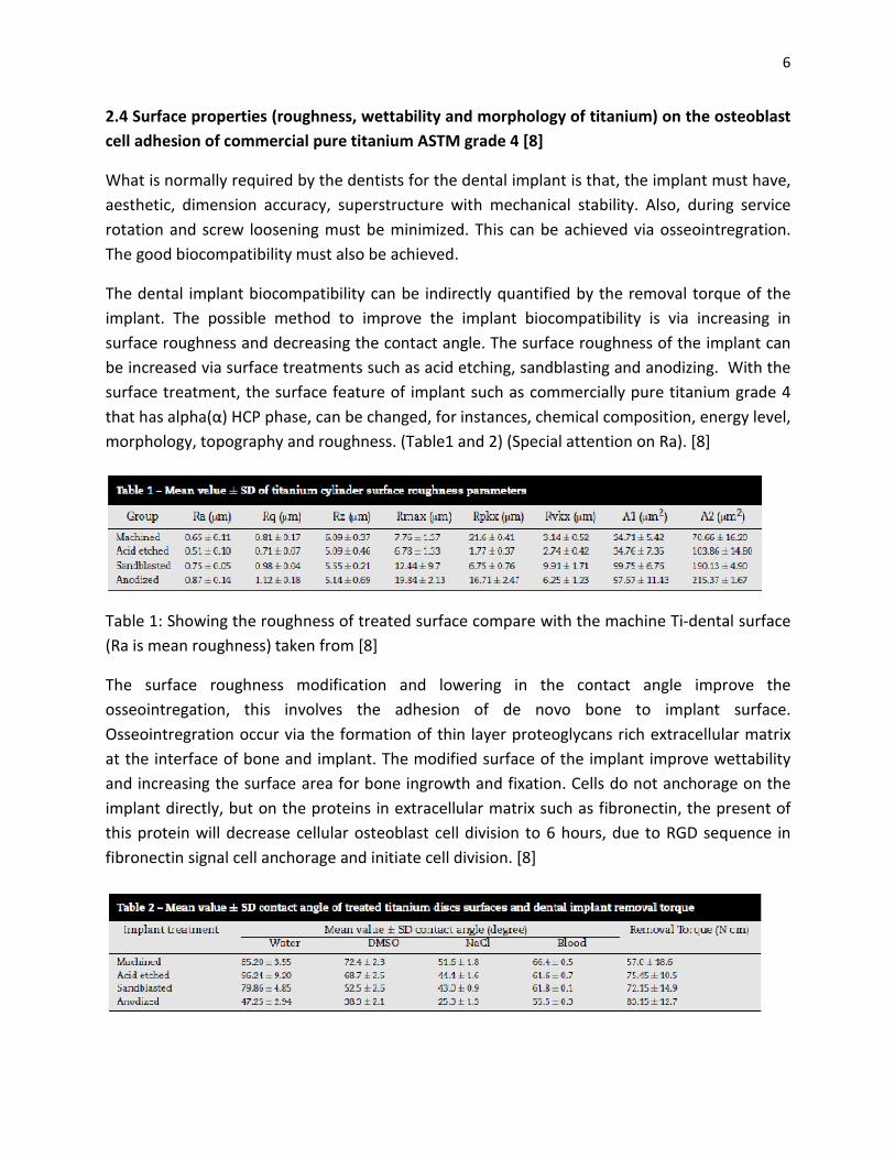
2.4 Surface properties (roughness, wettability and morphology of titanium) on the osteoblast
cell adhesion of commercial pure titanium ASTM grade 4 [8]
What is normally required by the dentists for the dental implant is that, the implant must have,
aesthetic, dimension accuracy, superstructure with mechanical stability. Also, during service
rotation and screw loosening must be minimized. This can be achieved via osseointregration.
The good biocompatibility must also be achieved.
The dental implant biocompatibility can be indirectly quantified by the removal torque of the
implant. The possible method to improve the implant biocompatibility is via increasing in
surface roughness and decreasing the contact angle. The surface roughness of the implant can
be increased via surface treatments such as acid etching, sandblasting and anodizing. With the
surface treatment, the surface feature of implant such as commercially pure titanium grade 4
that has alpha(α) HCP phase, can be changed, for instances, chemical composition, energy level,
morphology, topography and roughness. (Table1 and 2) (Special attention on Ra). [8]
Table 1: Showing the roughness of treated surface compare with the machine Ti-dental surface
(Ra is mean roughness) taken from [8]
The surface roughness modification and lowering in the contact angle improve the
osseointregation, this involves the adhesion of de novo bone to implant surface.
Osseointregration occur via the formation of thin layer proteoglycans rich extracellular matrix
at the interface of bone and implant. The modified surface of the implant improve wettability
and increasing the surface area for bone ingrowth and fixation. Cells do not anchorage on the
implant directly, but on the proteins in extracellular matrix such as fibronectin, the present of
this protein will decrease cellular osteoblast cell division to 6 hours, due to RGD sequence in
fibronectin signal cell anchorage and initiate cell division. [8]
7
Table 2: Showing the different in contact angle and torque removal of different treated surface
of Ti-implant, anodized surface (TiO2 layer forming) show highest torque removal, indicating
high osseointregration into the implant normally 1 to 10nm thickness of protein is absorbed
into the implant. Hypothetically, 1 to 10nm thickness layer of cell integrating with the implant
surface, taken from [8]
The contact angle indicate the surface hydrophilicity or hydrophobicity of the implant surface,
the anodized (oxidized) surface is the most hydrophilic. In the in vivo and in vitro test on
animals, it was found that the proliferation of the cells into the surface of the dental implant
increases with the increasing in the surface wettability. The fibroblasts have greater adhesion
on the hydrophilic surface than the hydrophobic. [8]
It was also observed that the higher the roughness surface value is, the higher the surface
energy and larger the number of hydroxyl groups, results in the greater number of adhered
osteoblasts and cell activity on the surface dental implant. The production of cell growth factor
such as TGF-b1 increases as the surface of implant get rough. Growth factor promote cellular
differentiation and cell division.[8]
In case of this project, the novel dental implant which is Ti-14%wtZr alloy, will likely to exhibit
the same behaviour as ASTM CP-Ti-grade 4, as it has the same phase as the studying dental
material Ti-14%Zr alloy, also Zr is completely miscible in titanium and does not affect the
crystallographic grain morphology of titanium.[8]
2.5 Shear band formation in the titanium grade 2 (alpha) phase
Two stages occur in the formation of the grade 2 (alpha) HCP structure due to high strain rate
plastic deformation, 1) instability which is produced by thermal softening and the process
involve in shear band formation is the motion of dislocation that is assisted by heat. 2)
Localization (poorly understood phenomenon) is caused by softening; major microstructure
changes due to recover and recrystallization within the band. The temperature rise that is
required for the instability and localization to occur within the alpha Ti grade 2, is around 350K
to 776K (76.85C to 502.85C). Recrystallization is approximately to occur at 0.4Tm of the
material. The heat that cause the localization comes from the transformation of plastic energy
during deformation into heat. Therefore, 0.4Tm is the temperature where localization is
initiated.[9][10]
Within the shear band, there is plastic instability that is caused by thermal softening, this
thermal softening process occur via one of dynamic recovery or recrystallization. Softening
causes lower in shear yield stress and discontinuity in the flow stress during material
deformation. This causes the defined boundaries between the shear band and the surrounding
material. The release of dislocation pile-up within the slip-plane during deformation causes
localised heating in the slip plane, and shear band is then formed. The heat g
adiabatic process. For ballistic deformation, the shear band is considered to be the precursor to
fragmentation and fracture.[9][10]
3. Objectives of this research project
The aim of this project is to find the optimum processing temperature o
Angular Pressing) for Ti-14%wtZr, lowest as much as possible, to give highest strength with
minimum scarification in Ti-14%wtZr alloy’s ductility. The investigated range of the processing
temperature will be around the alpha region of
keep the Ti-14%Zr alloy in alpha phase for further SLA
optimum processing temperature will allow the affordability of the Ti
with its best strength and ductility for minimizing the size of the implant for less pain infliction
when implant into the body.
The ECAP die comes into 10 mm in diameter however the given sample to studies is in
5mm and 8mm, therefore “can” material with thickness of
with the ECAP processing; this mean the core Ti
surrounded with 2.5mm and 1mm can material
CP-Ti grade 4 processing at different temperature, how these affect the microstructure of
ECAPed Ti14%wtZr are also being investigated, which are “
passes Ti-6Al-4V can at 500C”, “ECAPed 8mm core Ti
500C” and “ECAPed 5mm core Ti
The reason for processing at 500C for Ti6Al4V is because at this temperature, under
compression testing, the strain hardening rate is found to be
Under room temperature with compression
is ~1100MPa, while at 500C the compressive
be ~650MPa [17]. And processing at 400C for C
Ti6V4Al is too strong for deformation and therefore CP
Furthermore, the choice of the Ti
restricted by the manufacturer/supplier
patented material by Institut Straumann AG (Public).
localised heating in the slip plane, and shear band is then formed. The heat g
adiabatic process. For ballistic deformation, the shear band is considered to be the precursor to
[9][10]
3. Objectives of this research project
The aim of this project is to find the optimum processing temperature of ECAP(Equal Channel
14%wtZr, lowest as much as possible, to give highest strength with
14%wtZr alloy’s ductility. The investigated range of the processing
temperature will be around the alpha region of Ti-14%wtZr, approximately around 400
14%Zr alloy in alpha phase for further SLA or SLActive surface treatment.
optimum processing temperature will allow the affordability of the Ti-14%Zr dental implant
ctility for minimizing the size of the implant for less pain infliction
The ECAP die comes into 10 mm in diameter however the given sample to studies is in
5mm and 8mm, therefore “can” material with thickness of 2.5mm and 1mm are used to aid
with the ECAP processing; this mean the core Ti-14%wtZr is in diameter of 5mm and 8mm,
mm can material. Two different can materials are Ti6Al4V and
Ti grade 4 processing at different temperature, how these affect the microstructure of
ECAPed Ti14%wtZr are also being investigated, which are “ECAPed 5mm core Ti
at 500C”, “ECAPed 8mm core Ti-14%Zr alloy 4 passes Ti
500C” and “ECAPed 5mm core Ti-14%Zr alloy 4 passes CP-Ti grade 4 can at 400C”.
The reason for processing at 500C for Ti6Al4V is because at this temperature, under
strain hardening rate is found to be low and flow stress is lower.
nder room temperature with compression flow stress at 0.1 plastic strain with 1s
MPa, while at 500C the compressive flow stress, under the same conditions, is found to
. And processing at 400C for CP-Ti grade 4 is because, by lowering temperature
Ti6V4Al is too strong for deformation and therefore CP-Ti grade 4 is used instead
Furthermore, the choice of the Ti-14%wtZr rod dimension of 5 mm and 8 mm diameter is
restricted by the manufacturer/supplier Roxolid; Straumann. Noting that, this Ti
patented material by Institut Straumann AG (Public).
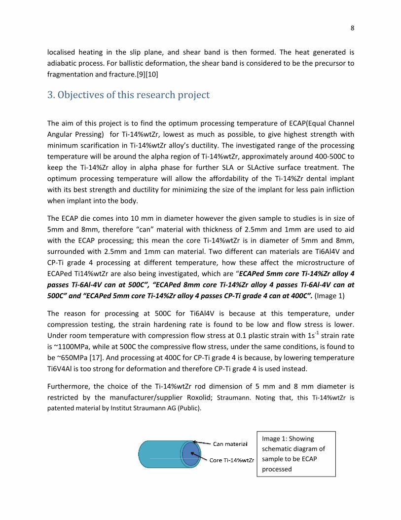
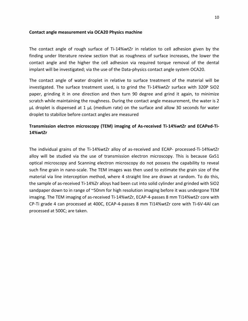
Image 1: Showing
schematic diagram of
sample to be ECAP
processed
8
localised heating in the slip plane, and shear band is then formed. The heat generated is
adiabatic process. For ballistic deformation, the shear band is considered to be the precursor to
f ECAP(Equal Channel
14%wtZr, lowest as much as possible, to give highest strength with
14%wtZr alloy’s ductility. The investigated range of the processing
14%wtZr, approximately around 400-500C to
or SLActive surface treatment. The
14%Zr dental implant
ctility for minimizing the size of the implant for less pain infliction
The ECAP die comes into 10 mm in diameter however the given sample to studies is in size of
mm are used to aid
14%wtZr is in diameter of 5mm and 8mm,
Two different can materials are Ti6Al4V and
Ti grade 4 processing at different temperature, how these affect the microstructure of
ECAPed 5mm core Ti-14%Zr alloy 4
14%Zr alloy 4 passes Ti-6Al-4V can at
at 400C”. (Image 1)
The reason for processing at 500C for Ti6Al4V is because at this temperature, under
ow stress is lower.
flow stress at 0.1 plastic strain with 1s-1 strain rate
flow stress, under the same conditions, is found to
Ti grade 4 is because, by lowering temperature
Ti grade 4 is used instead.
14%wtZr rod dimension of 5 mm and 8 mm diameter is
Straumann. Noting that, this Ti-14%wtZr is
Image 1: Showing
schematic diagram of
sample to be ECAP
9
4. Methodology/Experimental techniques
Optical microstructure revelation of Ti-14wt%Zr alloy
The microstructure of As-Received Ti-Zr alloys will be investigated in order to determine the link
of how grain size can affect the mechanical properties of material. Microstructure revelation of
As-received Ti-14wt%Zr alloy material is found by first, cutting the sample in cross-sectional
direction and longitudinal direction. It is then allowed to grind (400, 500, 600, 1000, 4000 SiO2
paper), polish (with OPS solution) and chemical etching (to reveal grain boundaries). The
polished/etched Ti-14%Zr microstructure is then observed under Olympus GX51 microscope for
grain size and its textures.
Scanning electron microscopy
Using high energy electrons of 15kV as light source to obtain better resolution of the image
than the GX51 optical imaging, the images of sample are taken in various area of cross-sectional
and longitudinal direction Ti-14%Zr sample. (Figure 5)
Microhardness test of As-received Ti-14wt%Zr alloy
The purpose of micro-hardness testing is to compare the result of microhardness test with the tensile
testing data, in order to determine tensile testing data accuracy of Ti-14%wtZr alloy. The Vicker’s
microhardness is used with the force of 300g and 500g are used to find the hardness (HV) of the Ti-
14wt%Zr, the HV value can then be related to yield strength of Ti-14wt%Zr via following relationship:
3�� = ��(��������ℎ�������)[13]. The tests are performed on two different texture orientations of
As-received Ti-14%wtZr alloy. (Table 4)
Tensile testing of As-received Ti-14%wtZr
The yield strength, tensile strength and uniform elongation of As-received Ti-14%wtZr will be
determined by tensile testing, which was done in according to ASTM E8 standard at room
temperature 25C, at low strain rate of 1mm/min cross-head speed, using Intron 5900 series.
The test sample is dog-bone with gage length of 10mm±0.1mm and diameter of 2.5±0.1mm
(Figure 16)
Tensile facture surface analysis of As-received and 4 ECAP Passes at temperature of 500C and
400C with varying in can-aided ECAP material of Titanium Zirconium alloys
The fracture behavior and associated microstructure characteristic of Ti-14%wtZr alloy will be
determined and revealed, which indicates by the present of microvoids (dimples). This will be
done by the use of Phenom Scanning electron microscopy machine and FEI Scanning electron
microscopy with electron energy of 15kV
10
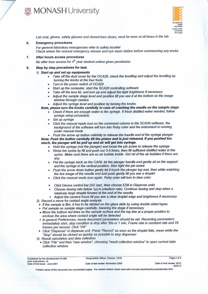
Contact angle measurement via OCA20 Physics machine
The contact angle of rough surface of Ti-14%wtZr in relation to cell adhesion given by the
finding under literature review section that as roughness of surface increases, the lower the
contact angle and the higher the cell adhesion via required torque removal of the dental
implant will be investigated; via the use of the Data-physics contact angle system OCA20.
The contact angle of water droplet in relative to surface treatment of the material will be
investigated. The surface treatment used, is to grind the Ti-14%wtZr surface with 320P SiO2
paper, grinding it in one direction and then turn 90 degree and grind it again, to minimize
scratch while maintaining the roughness. During the contact angle measurement, the water is 2
μL droplet is dispensed at 1 µL (medium rate) on the surface and allow 30 seconds for water
droplet to stabilize before contact angles are measured
Transmission electron microscopy (TEM) imaging of As-received Ti-14%wtZr and ECAPed-Ti-
14%wtZr
The individual grains of the Ti-14%wtZr alloy of as-received and ECAP- processed-Ti-14%wtZr
alloy will be studied via the use of transmission electron microscopy. This is because Gx51
optical microscopy and Scanning electron microscopy do not possess the capability to reveal
such fine grain in nano-scale. The TEM images was then used to estimate the grain size of the
material via line interception method, where 4 straight line are drawn at random. To do this,
the sample of as-received Ti-14%Zr alloys had been cut into solid cylinder and grinded with SiO2
sandpaper down to in range of ~50nm for high resolution imaging before it was undergone TEM
imaging. The TEM imaging of as-received Ti-14%wtZr, ECAP-4-passes 8 mm Ti14%wtZr core with
CP-Ti grade 4 can processed at 400C, ECAP-4-passes 8 mm Ti14%wtZr core with Ti-6V-4Al can
processed at 500C; are taken.
11
5. Material Specification
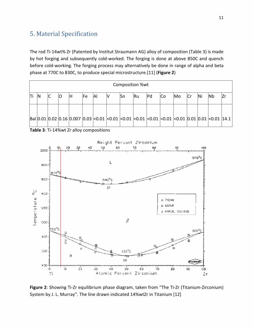
The rod Ti-14wt% Zr (Patented by Institut Straumann AG) alloy of composition (Table 3) is made
by hot forging and subsequently cold-worked. The forging is done at above 850C and quench
before cold-working. The forging process may alternatively be done in range of alpha and beta
phase at 770C to 830C, to produce special microstructure.[11] (Figure 2)
Composition %wt
Ti N C O H Fe Al V Sn Ru Pd Co Mo Cr Ni Nb Zr
Bal 0.01 0.02 0.16 0.007 0.03 <0.01 <0.01 <0.01 <0.01 <0.01 <0.01 <0.01 0.01 0.01 <0.01 14.1
Table 3: Ti-14%wt Zr alloy compositions
Figure 2: Showing Ti-Zr equilibrium phase diagram, taken from “The Ti-Zr (Titanium-Zirconium)
System by J. L. Murray”. The line drawn indicated 14%wtZr in Titanium [12]
12
I. Results and Discussion
6. Optical microstructure revelation of Ti-14wt%Zr alloy
6.1 Microstructure revelation of As-received Ti-14wt%Zr alloy and ECAPed-Ti14%wtZr result
and discussion
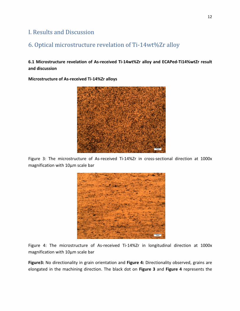
Microstructure of As-received Ti-14%Zr alloys
Figure 3: The microstructure of As-received Ti-14%Zr in cross-sectional direction at 1000x
magnification with 10μm scale bar
Figure 4: The microstructure of As-received Ti-14%Zr in longitudinal direction at 1000x
magnification with 10μm scale bar
Figure3: No directionality in grain orientation and Figure 4: Directionality observed, grains are
elongated in the machining direction. The black dot on Figure 3 and Figure 4 represents the
13
non-uniformly etched surface of the sample and due to limitation in magnification, grain
boundaries are not shown on the image figure 3 and figure 4.
7. SEM imaging of the As-received Ti-14%Zr alloy
7.1 SEM imaging of the As-received Ti-14%Zr alloy in cross-sectional direction
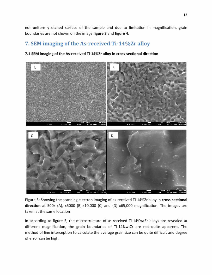
Figure 5: Showing the scanning electron imaging of as-received Ti-14%Zr alloy in cross-sectional
direction at 500x (A), x5000 (B),x10,000 (C) and (D) x65,000 magnification. The images are
taken at the same location
In according to figure 5, the microstructure of as-received Ti-14%wtZr alloys are revealed at
different magnification, the grain boundaries of Ti-14%wtZr are not quite apparent. The
method of line interception to calculate the average grain size can be quite difficult and degree
of error can be high.
A B
C D
14
7.2 SEM imaging of the As-received Ti-14%Zr alloy in longitudinal direction
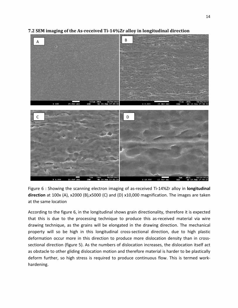
Figure 6 : Showing the scanning electron imaging of as-received Ti-14%Zr alloy in longitudinal
direction at 100x (A), x2000 (B),x5000 (C) and (D) x10,000 magnification. The images are taken
at the same location
According to the figure 6, in the longitudinal shows grain directionality, therefore it is expected
that this is due to the processing technique to produce this as-received material via wire
drawing technique, as the grains will be elongated in the drawing direction. The mechanical
property will so be high in this longitudinal cross-sectional direction, due to high plastic
deformation occur more in this direction to produce more dislocation density than in cross-
sectional direction (figure 5). As the numbers of dislocation increases, the dislocation itself act
as obstacle to other gliding dislocation motion and therefore material is harder to be plastically
deform further, so high stress is required to produce continuous flow. This is termed work-
hardening.
A B
C D
15
8. Investigation on whether different can material used during
ECAP processing will affect microstructure of ECAP processed
Ti-14%wtZr in cross-sectional and longitudinal direction
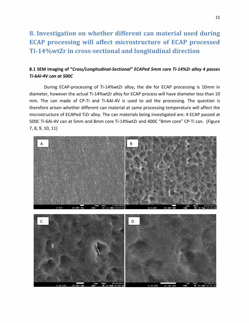
8.1 SEM imaging of “Cross/Longitudinal-Sectional” ECAPed 5mm core Ti-14%Zr alloy 4 passes
Ti-6Al-4V can at 500C
During ECAP-processing of Ti-14%wtZr alloy, the die for ECAP processing is 10mm in
diameter, however the actual Ti-14%wtZr alloy for ECAP process will have diameter less than 10
mm. The can made of CP-Ti and Ti-6Al-4V is used to aid the processing. The question is
therefore arisen whether different can material at same processing temperature will affect the
microstructure of ECAPed TiZr alloy. The can materials being investigated are: 4 ECAP passed at
500C Ti-6Al-4V can at 5mm and 8mm core Ti-14%wtZr and 400C “8mm core” CP-Ti can. (Figure
7, 8, 9, 10, 11)
A B
C D
16
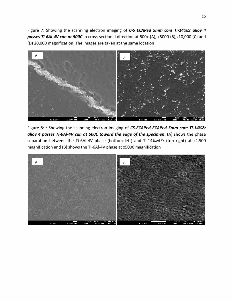
Figure 7: Showing the scanning electron imaging of C-S ECAPed 5mm core Ti-14%Zr alloy 4
passes Ti-6Al-4V can at 500C in cross-sectional direction at 500x (A), x5000 (B),x10,000 (C) and
(D) 20,000 magnification. The images are taken at the same location
Figure 8: : Showing the scanning electron imaging of CS-ECAPed ECAPed 5mm core Ti-14%Zr
alloy 4 passes Ti-6Al-4V can at 500C toward the edge of the specimen, (A) shows the phase
separation between the Ti-6Al-4V phase (bottom left) and Ti-14%wtZr (top right) at x4,500
magnification and (B) shows the Ti-6Al-4V phase at x5000 magnification
A B
A B
17
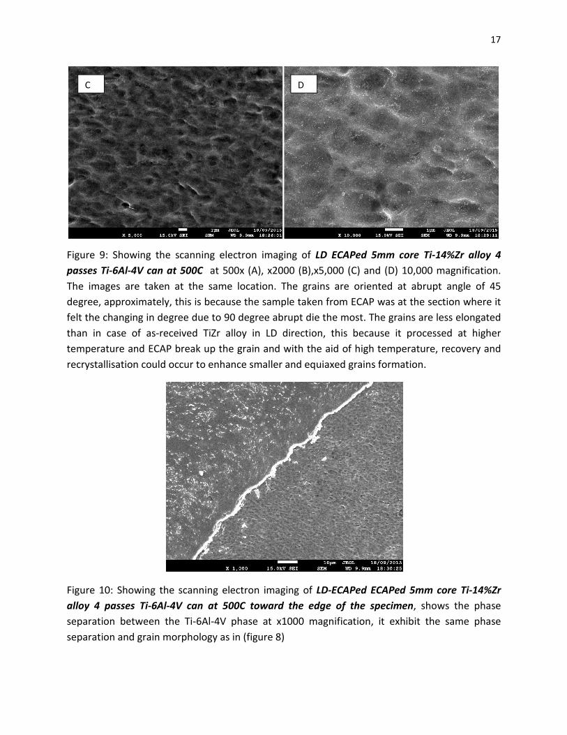
Figure 9: Showing the scanning electron imaging of LD ECAPed 5mm core Ti-14%Zr alloy 4
passes Ti-6Al-4V can at 500C at 500x (A), x2000 (B),x5,000 (C) and (D) 10,000 magnification.
The images are taken at the same location. The grains are oriented at abrupt angle of 45
degree, approximately, this is because the sample taken from ECAP was at the section where it
felt the changing in degree due to 90 degree abrupt die the most. The grains are less elongated
than in case of as-received TiZr alloy in LD direction, this because it processed at higher
temperature and ECAP break up the grain and with the aid of high temperature, recovery and
recrystallisation could occur to enhance smaller and equiaxed grains formation.
Figure 10: Showing the scanning electron imaging of LD-ECAPed ECAPed 5mm core Ti-14%Zr
alloy 4 passes Ti-6Al-4V can at 500C toward the edge of the specimen, shows the phase
separation between the Ti-6Al-4V phase at x1000 magnification, it exhibit the same phase
separation and grain morphology as in (figure 8)
C D
18
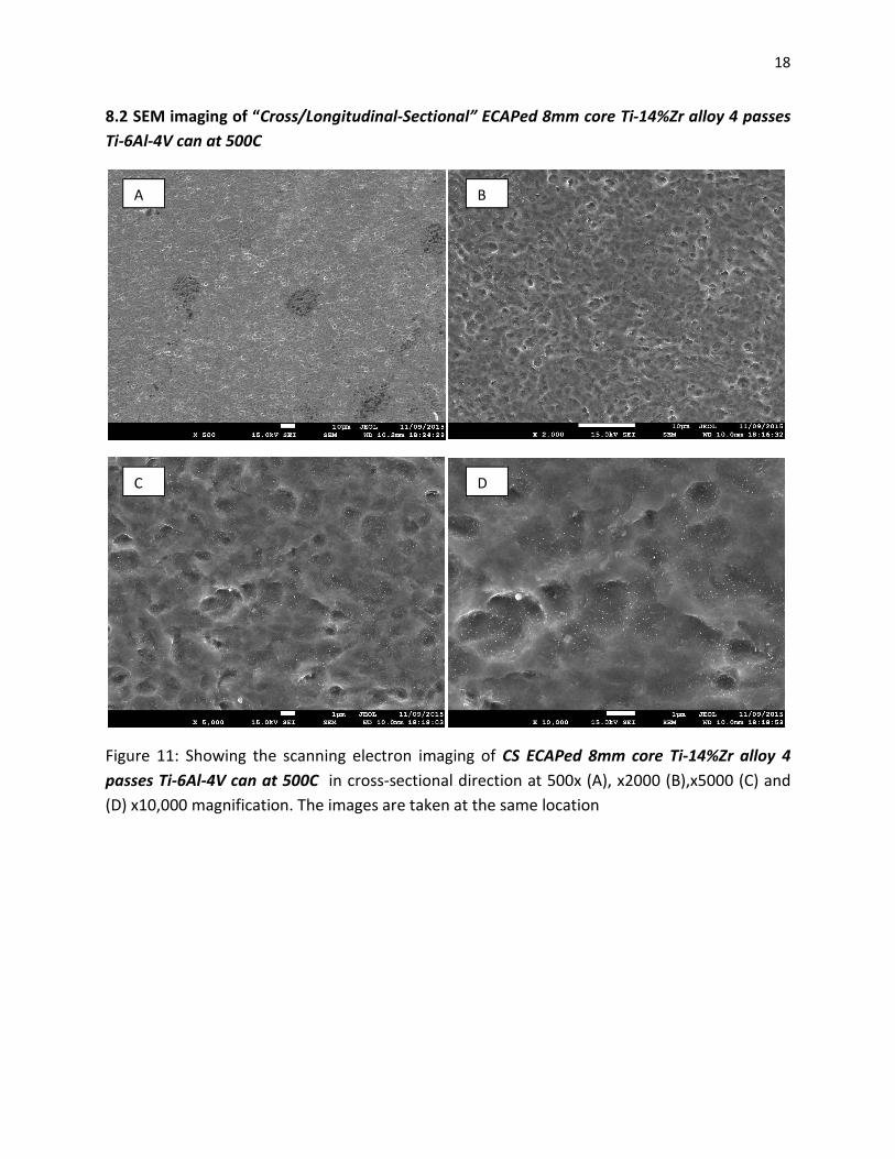
8.2 SEM imaging of “Cross/Longitudinal-Sectional” ECAPed 8mm core Ti-14%Zr alloy 4 passes
Ti-6Al-4V can at 500C
Figure 11: Showing the scanning electron imaging of CS ECAPed 8mm core Ti-14%Zr alloy 4
passes Ti-6Al-4V can at 500C in cross-sectional direction at 500x (A), x2000 (B),x5000 (C) and
(D) x10,000 magnification. The images are taken at the same location
A B
C D
19
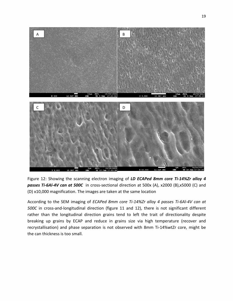
Figure 12: Showing the scanning electron imaging of LD ECAPed 8mm core Ti-14%Zr alloy 4
passes Ti-6Al-4V can at 500C in cross-sectional direction at 500x (A), x2000 (B),x5000 (C) and
(D) x10,000 magnification. The images are taken at the same location
According to the SEM imaging of ECAPed 8mm core Ti-14%Zr alloy 4 passes Ti-6Al-4V can at
500C in cross-and-longitudinal direction (figure 11 and 12), there is not significant different
rather than the longitudinal direction grains tend to left the trait of directionality despite
breaking up grains by ECAP and reduce in grains size via high temperature (recover and
recrystallisation) and phase separation is not observed with 8mm Ti-14%wtZr core, might be
the can thickness is too small.
C
A B
D
20
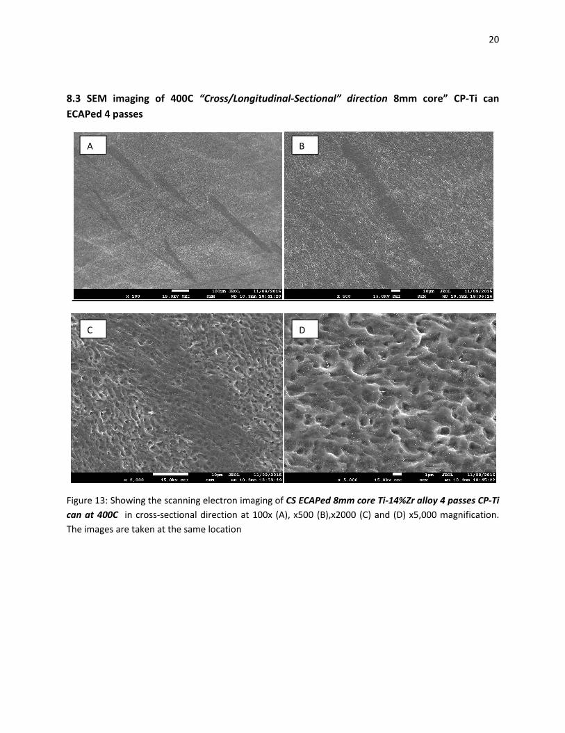
8.3 SEM imaging of 400C “Cross/Longitudinal-Sectional” direction 8mm core” CP-Ti can
ECAPed 4 passes
Figure 13: Showing the scanning electron imaging of CS ECAPed 8mm core Ti-14%Zr alloy 4 passes CP-Ti
can at 400C in cross-sectional direction at 100x (A), x500 (B),x2000 (C) and (D) x5,000 magnification.
The images are taken at the same location
A B
C D
21
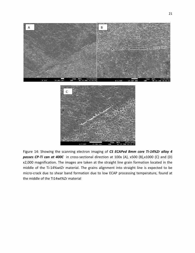
Figure 14: Showing the scanning electron imaging of CS ECAPed 8mm core Ti-14%Zr alloy 4
passes CP-Ti can at 400C in cross-sectional direction at 100x (A), x500 (B),x1000 (C) and (D)
x2,000 magnification. The images are taken at the straight line grain formation located in the
middle of the Ti-14%wtZr material. The grains alignment into straight line is expected to be
micro-crack due to shear band formation due to low ECAP processing temperature, found at
the middle of the Ti14wt%Zr material
A B
C
22
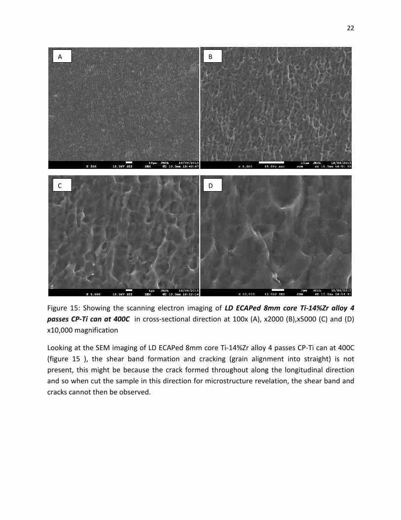
Figure 15: Showing the scanning electron imaging of LD ECAPed 8mm core Ti-14%Zr alloy 4
passes CP-Ti can at 400C in cross-sectional direction at 100x (A), x2000 (B),x5000 (C) and (D)
x10,000 magnification
Looking at the SEM imaging of LD ECAPed 8mm core Ti-14%Zr alloy 4 passes CP-Ti can at 400C
(figure 15 ), the shear band formation and cracking (grain alignment into straight) is not
present, this might be because the crack formed throughout along the longitudinal direction
and so when cut the sample in this direction for microstructure revelation, the shear band and
cracks cannot then be observed.
A B
C D

23
9. Comparing how different can material affect the
microstructure of ECAPed Ti-14%wtZr alloy
Considering “ECAPed 5mm core Ti-14%wtZr alloy 4 passes at 500C” figure 8, it can clearly be seen that
there is a phase separation, separated by the white line on the image. The bottom left of the image is
phase of Ti-6Al-4V alloy while the top right corner is ECAPed Ti-14%Zr alloy, the can will be separated
from the actual Ti-Zr alloy and machine into dog-bone shape for tensile testing. The clear phase
separation of Ti-6Al-4V and Ti-Zr alloy suggest that the can material of Ti-6Al-4V will not affect the
microstructure of ECAPed Ti-Zr alloy. Now consider, CP-Ti grade 4 can processed at lower temperature
of 400C at 8mm core, by observing grain morphology visually (figure 13 and 14), it does not look
different from the other in figure 7 and 8.Therefore, CP-Ti grade 4 can does not also affect the
microstructure of ECAPed Ti-Zr alloy.
However, for the CP-Ti grade 4 can processed at lower temperature than figure 6 and 8 at 400C instead
of 500C. The localized shear band formation occur be observed quite clearly (figure 9A) across the
surface of the ECAPed Ti-Zr alloy. The shear band is not desirable, this is due to it can act as precursor to
fragmentation and fracture during deformation. The orientation of the grains of ECAPed TiZr alloy within
the shear band are also oriented at different direction from the neighboring grains of the ECAPed Ti-Zr
alloy. [9][10]
Processing at lower temperature of ECAPed Ti-Zr alloy at 400C rather than 500C, hypothetically, induced
the recovery and recrystallization processes during ECAP-processing at certain area of ECAPed Ti-Zr
alloy. The area of shear band formation therefore has lower shear stress due to annihilation of
dislocation via recovery and different grain orientation due to recrystallization. This discontinuity in flow
stress during ECAP deformation is the result of the apparent shear band formation within the structure.
The shear band grain hence deformed more and flow in direction of ECAP superplastic deformation
easier than its neighboring are. This maybe the reason why the orientation of the ECAPed Ti-Zr alloy
grains within the shear band seems to be flowed into certain direction. [9][10]
Note that, the longitudinal direction section is not discussed here, because the only different is grain
orientation in machining direction of cold wire drawing, even through the material was processed at
high temperature, the expected directionality should be eliminated via recovery and recrystallisation
and ECAP-breaking up the grains; in processing nothing can be getting rid of completely.
24
10. Investigation on the mechanical properties of As-Received
Ti-14%Zr alloy The main aim of this project is to develop high strength with little scarification in material
ductility via the ECAP super plastic deformation, the mechanical properties of as-received
material is then needed to be investigated for comparison purpose whether there is any
improvement and what had been sacrificed via ECAP processing. It was stated early that Ti-Zr
alloy has higher strength than CP-Ti grade 4, the mechanical properties of Ti-14%Zr alloy will
then be investigated and discuss under this section. Two methods are used to find out the
mechanical properties, which are yield strength of Ti-14%wtZr alloy by correlation between
(micro) hardness and yield strength and the actual tensile testing.
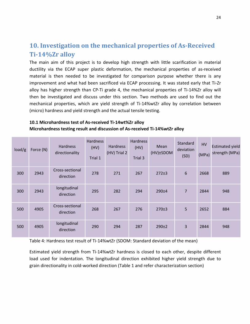
10.1 Microhardness test of As-received Ti-14wt%Zr alloy
Microhardness testing result and discussion of As-received Ti-14%wtZr alloy
load/g Force (N) Hardness
directionality
Hardness
(HV)
Trial 1
Hardness
(HV) Trial 2
Hardness
(HV)
Trial 3
Mean
(HV)±SDOM
Standard
deviation
(SD)
HV
(MPa)
Estimated yield
strength (MPa)
300 2943 Cross-sectional
direction 278 271 267 272±3 6 2668 889
300 2943 longitudinal
direction 295 282 294 290±4 7 2844 948
500 4905 Cross-sectional
direction 268 267 276 270±3 5 2652 884
500 4905 longitudinal
direction 290 294 287 290±2 3 2844 948
Table 4: Hardness test result of Ti-14%wtZr (SDOM: Standard deviation of the mean)
Estimated yield strength from Ti-14%wtZr hardness is closed to each other, despite different
load used for indentation. The longitudinal direction exhibited higher yield strength due to
grain directionality in cold-worked direction (Table 1 and refer characterization section)
25
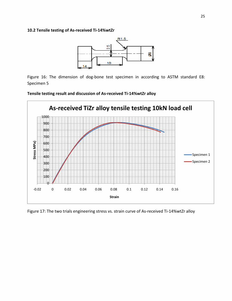
10.2 Tensile testing of As-received Ti-14%wtZr
Figure 16: The dimension of dog-bone test specimen in according to ASTM standard E8:
Specimen 5
Tensile testing result and discussion of As-received Ti-14%wtZr alloy
Figure 17: The two trials engineering stress vs. strain curve of As-received Ti-14%wtZr alloy
0
100
200
300
400
500
600
700
800
900
1000
-0.02 0 0.02 0.04 0.06 0.08 0.1 0.12 0.14 0.16
Stre
ss M
Pa)
Strain
As-received TiZr alloy tensile testing 10kN load cell
Specimen 1
Specimen 2
26
Material: As-received Ti-14%wtZr
yield strength 0.2% strain (MPa)
σUTS (MPa)
Uniform elongation(ԑu)
Uniform elongation(ԑu)%
Young Modulus (GPa)
Specimen 1 640 915 0.09 9
22
Specimen 2 600 914 0.08 8
21
Standard deviation 28 0.2 0.004 1
656
Mean 620 914 0.08 8.5
22
Standard deviation of the mean 20 0.1 0.003 0.5
0.464
Table 5: The derived mechanical properties of as-received Ti-14%Zr alloy from tensile testing
graph
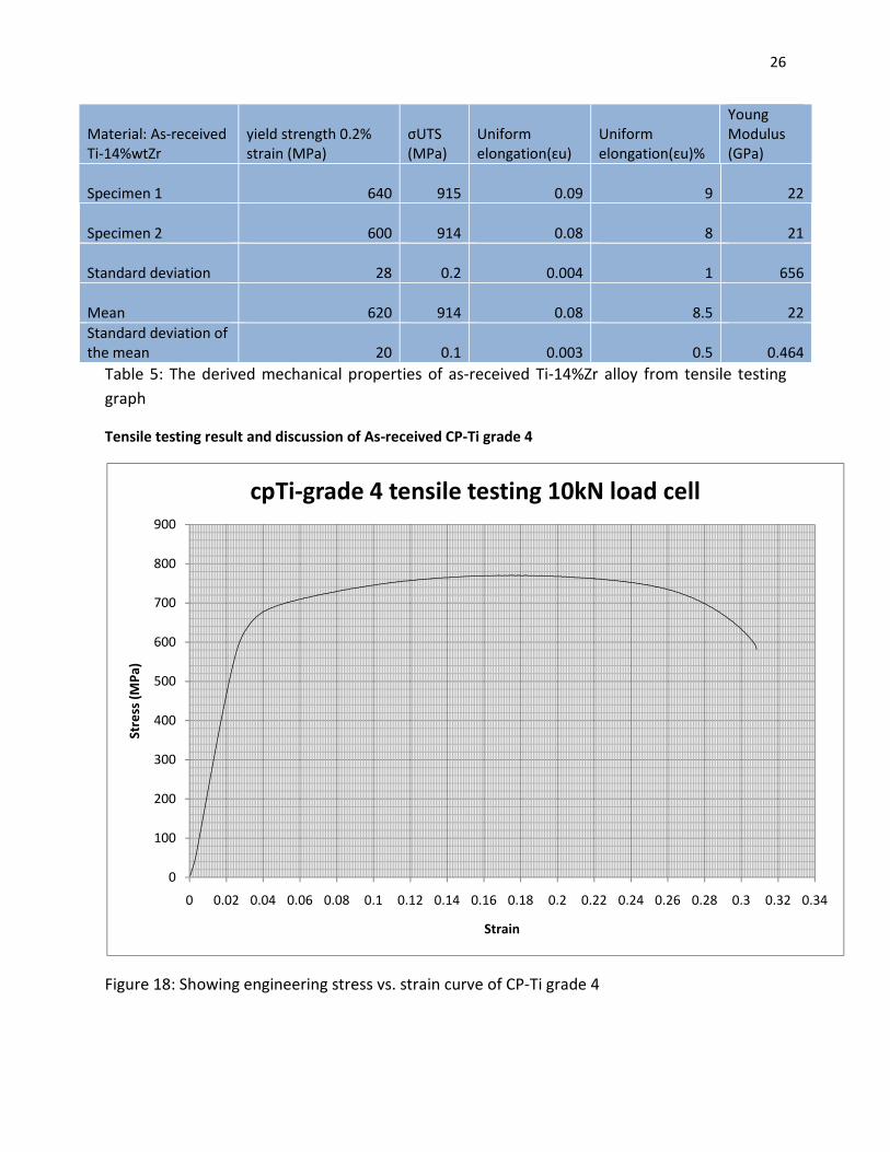
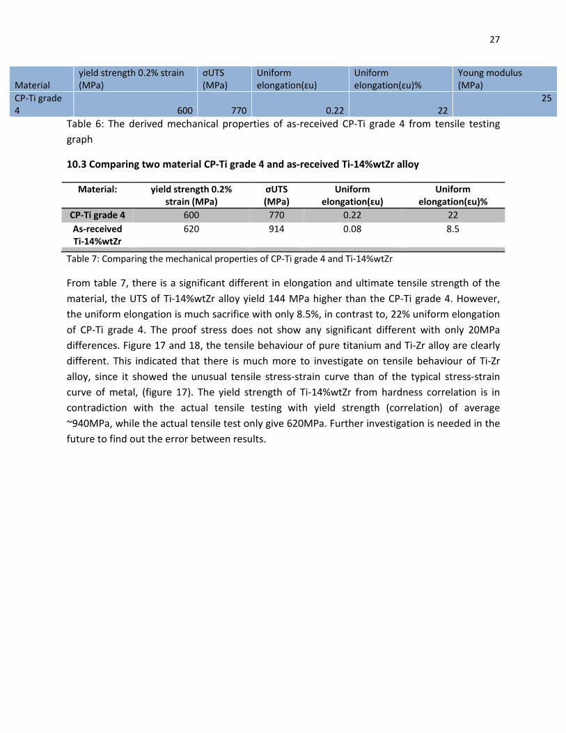
Tensile testing result and discussion of As-received CP-Ti grade 4
Figure 18: Showing engineering stress vs. strain curve of CP-Ti grade 4
0
100
200
300
400
500
600
700
800
900
0 0.02 0.04 0.06 0.08 0.1 0.12 0.14 0.16 0.18 0.2 0.22 0.24 0.26 0.28 0.3 0.32 0.34
Stre
ss (
MP
a)
Strain
cpTi-grade 4 tensile testing 10kN load cell
27
Material yield strength 0.2% strain (MPa)
σUTS (MPa)
Uniform elongation(ԑu)
Uniform elongation(ԑu)%
Young modulus (MPa)
CP-Ti grade 4 600 770 0.22 22
25
Table 6: The derived mechanical properties of as-received CP-Ti grade 4 from tensile testing
graph
10.3 Comparing two material CP-Ti grade 4 and as-received Ti-14%wtZr alloy
Material: yield strength 0.2% strain (MPa)
σUTS (MPa)
Uniform elongation(ԑu)
Uniform elongation(ԑu)%
CP-Ti grade 4 600 770 0.22 22
As-received Ti-14%wtZr
620 914 0.08 8.5
Table 7: Comparing the mechanical properties of CP-Ti grade 4 and Ti-14%wtZr
From table 7, there is a significant different in elongation and ultimate tensile strength of the
material, the UTS of Ti-14%wtZr alloy yield 144 MPa higher than the CP-Ti grade 4. However,
the uniform elongation is much sacrifice with only 8.5%, in contrast to, 22% uniform elongation
of CP-Ti grade 4. The proof stress does not show any significant different with only 20MPa
differences. Figure 17 and 18, the tensile behaviour of pure titanium and Ti-Zr alloy are clearly
different. This indicated that there is much more to investigate on tensile behaviour of Ti-Zr
alloy, since it showed the unusual tensile stress-strain curve than of the typical stress-strain
curve of metal, (figure 17). The yield strength of Ti-14%wtZr from hardness correlation is in
contradiction with the actual tensile testing with yield strength (correlation) of average
~940MPa, while the actual tensile test only give 620MPa. Further investigation is needed in the
future to find out the error between results.
28
11. Mechanical properties of ECAPed Ti-14%wt Zr alloy using
different can material and processing temperature
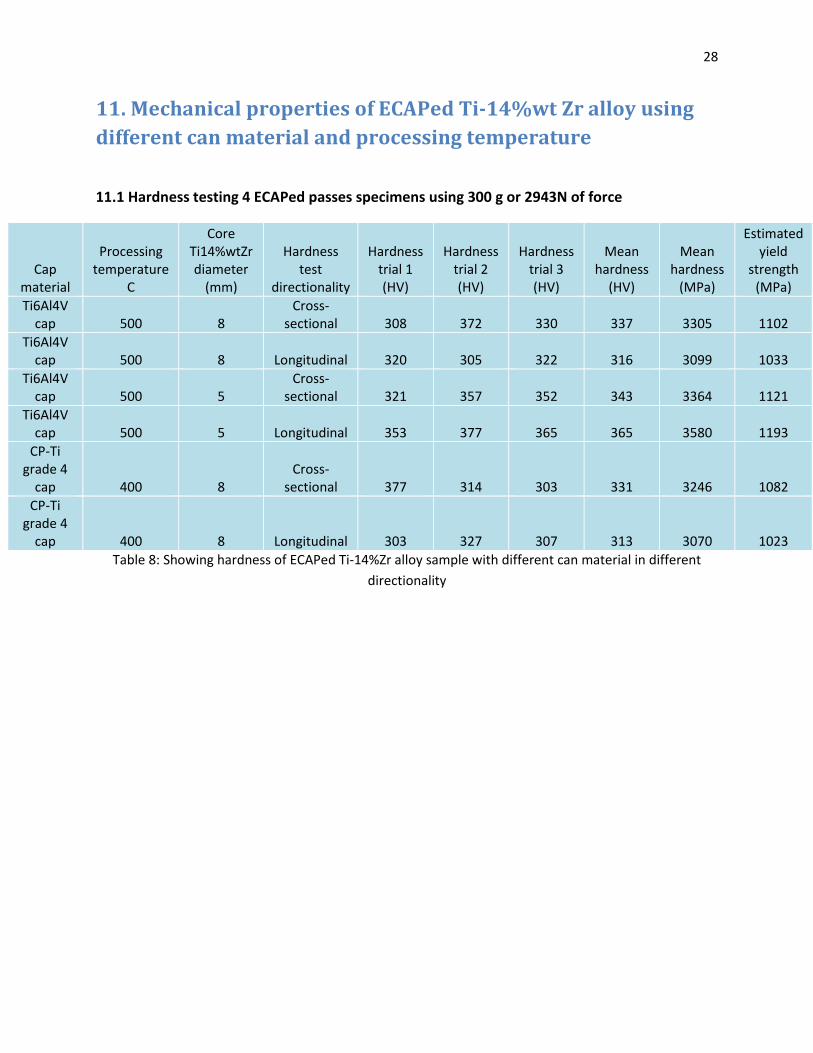
11.1 Hardness testing 4 ECAPed passes specimens using 300 g or 2943N of force
Cap material
Processing temperature
C
Core Ti14%wtZr diameter
(mm)
Hardness test
directionality
Hardness trial 1 (HV)
Hardness trial 2 (HV)
Hardness trial 3 (HV)
Mean hardness
(HV)
Mean hardness
(MPa)
Estimated yield
strength (MPa)
Ti6Al4V cap 500 8
Cross-sectional 308 372 330 337 3305 1102
Ti6Al4V cap 500 8 Longitudinal 320 305 322 316 3099 1033
Ti6Al4V cap 500 5
Cross-sectional 321 357 352 343 3364 1121
Ti6Al4V cap 500 5 Longitudinal 353 377 365 365 3580 1193
CP-Ti grade 4
cap 400 8 Cross-
sectional 377 314 303 331 3246 1082
CP-Ti grade 4
cap 400 8 Longitudinal 303 327 307 313 3070 1023
Table 8: Showing hardness of ECAPed Ti-14%Zr alloy sample with different can material in different
directionality
29
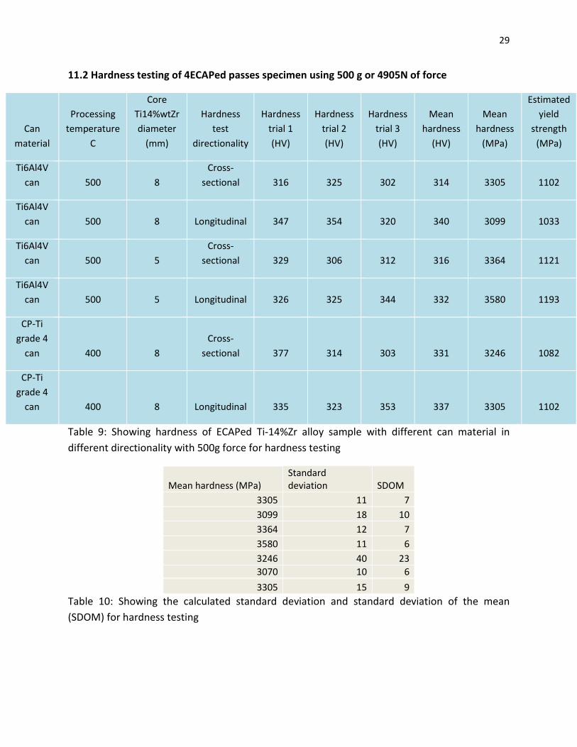
11.2 Hardness testing of 4ECAPed passes specimen using 500 g or 4905N of force
Can
material
Processing
temperature
C
Core
Ti14%wtZr
diameter
(mm)
Hardness
test
directionality
Hardness
trial 1
(HV)
Hardness
trial 2
(HV)
Hardness
trial 3
(HV)
Mean
hardness
(HV)
Mean
hardness
(MPa)
Estimated
yield
strength
(MPa)
Ti6Al4V
can 500 8
Cross-
sectional 316 325 302 314 3305 1102
Ti6Al4V
can 500 8 Longitudinal 347 354 320 340 3099 1033
Ti6Al4V
can 500 5
Cross-
sectional 329 306 312 316 3364 1121
Ti6Al4V
can 500 5 Longitudinal 326 325 344 332 3580 1193
CP-Ti
grade 4
can 400 8
Cross-
sectional 377 314 303 331 3246 1082
CP-Ti
grade 4
can 400 8 Longitudinal 335 323 353 337 3305 1102
Table 9: Showing hardness of ECAPed Ti-14%Zr alloy sample with different can material in
different directionality with 500g force for hardness testing
Mean hardness (MPa) Standard deviation SDOM
3305 11 7
3099 18 10
3364 12 7
3580 11 6
3246 40 23
3070 10 6
3305 15 9
Table 10: Showing the calculated standard deviation and standard deviation of the mean
(SDOM) for hardness testing
30
According to table 8 and 9, different force used for the hardness testing did not affect the
estimated yield strength of the material and there is no significant different in hardness and
yield strength value on the directionalities of the sample those samples are tested on.
Comparing the estimated yield strength via the use of hardness and yield strength correlation
of as-received Ti-14%wtZr alloy and ECAPed Ti-14%Zr alloy, table 4 and table 9; it can clearly be
seen that the estimated yield strength of 4 ECAPed passes TiZr alloy is on average 1092 MPa,
while as received TiZr alloy has the average estimated yield strength of 919 MPa. The rise of
~100MPa might be the result of reducing in the grain size of the material. However, the rise of
yield strength is not that significant and therefore it could be stated that, in according to Hall-
Petch theory, the effective strengthening coefficient k is not that high in Ti-14%Zr alloy.
12. Tensile facture surface analysis of As-received and 4 ECAP
Passes at temperature of 500C and 400C with varying in can-
aided ECAP material of Titanium Zirconium alloys
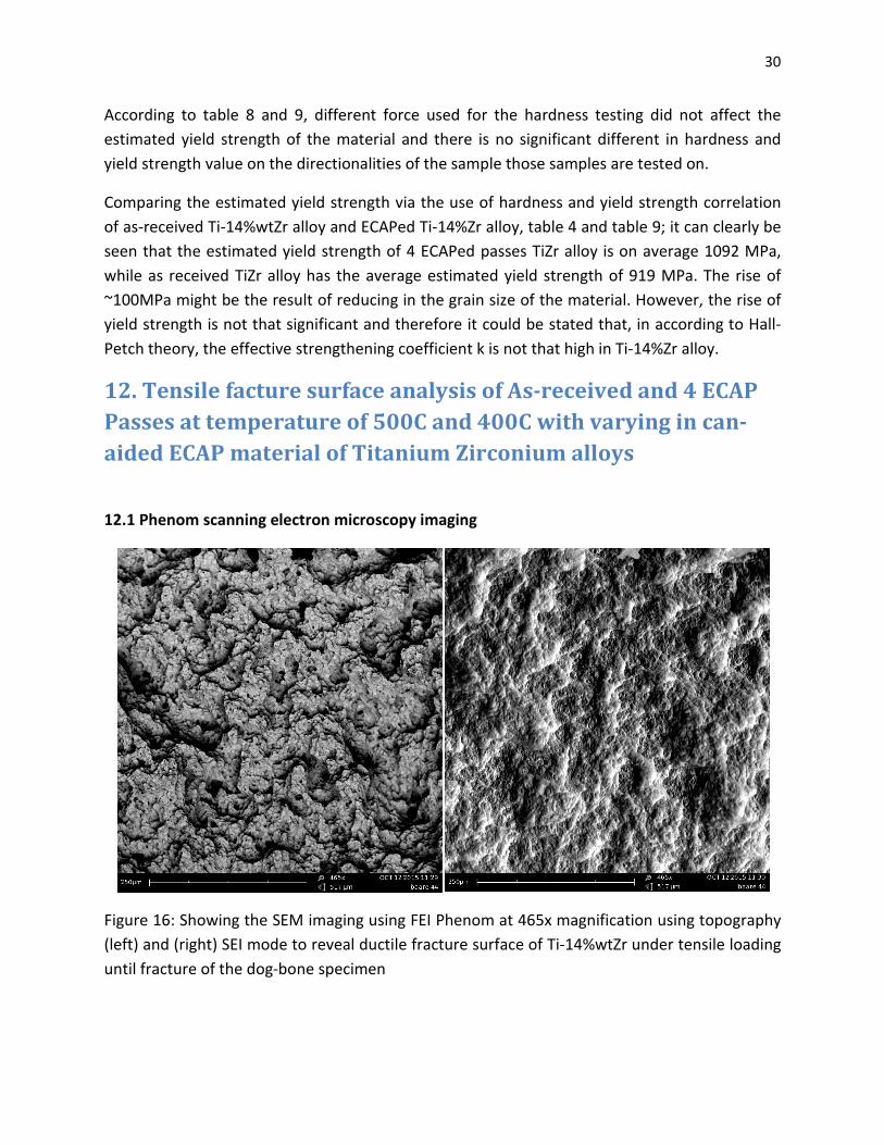
12.1 Phenom scanning electron microscopy imaging
Figure 16: Showing the SEM imaging using FEI Phenom at 465x magnification using topography
(left) and (right) SEI mode to reveal ductile fracture surface of Ti-14%wtZr under tensile loading
until fracture of the dog-bone specimen
31
In according to the figure 16, the Ti-14%Zr alloy failed by the ductile failure under the tension
test, many characteristic of ductile failure is present in the SEM image. The fracture surface is
also rather rough and form dimples that is produced by microvoid coalescence during tensile
drawing, instead of flat facet cleavage surface that is commonly observed in brittle fracture
(Brittle fracture will involves: intergranular and transgranular fracture, which in this case, are
not observed to be present). In term of macroscopic scale of fracture surface, the tensile
sample of Ti-Zr alloy showed cup-and-cone characteristic, which is an indication of ductile
fracture characteristic. The fracture of the metallic alloy is the result of the nucleation
microvoids during tension within the structure, followed by growth of microvoids as stretching
proceed and coalescence to form micro-or-macroscopic cracks. The formation of microvoids is
attributed to cracking of particles or interfacial failure between precipitate particles or an
inclusion and the metal matrix. The microvoids here, is orientated in direction of tensile testing.
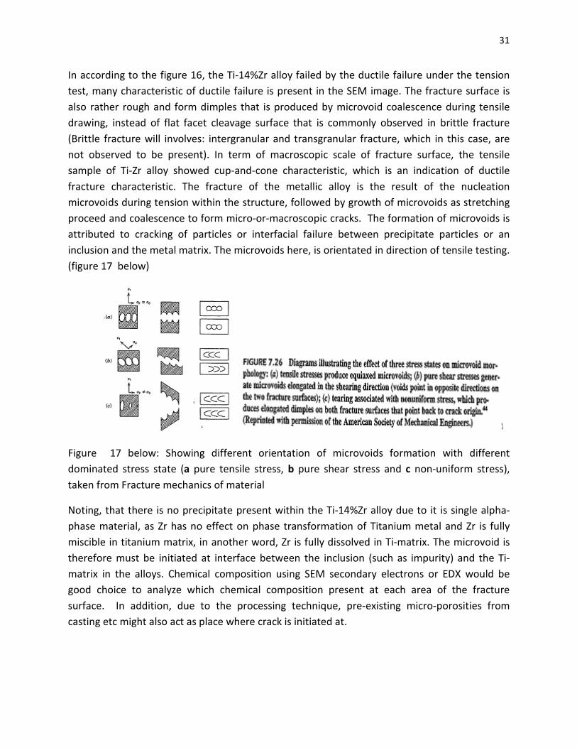
(figure 17 below)
Figure 17 below: Showing different orientation of microvoids formation with different
dominated stress state (a pure tensile stress, b pure shear stress and c non-uniform stress),
taken from Fracture mechanics of material
Noting, that there is no precipitate present within the Ti-14%Zr alloy due to it is single alpha-
phase material, as Zr has no effect on phase transformation of Titanium metal and Zr is fully
miscible in titanium matrix, in another word, Zr is fully dissolved in Ti-matrix. The microvoid is
therefore must be initiated at interface between the inclusion (such as impurity) and the Ti-
matrix in the alloys. Chemical composition using SEM secondary electrons or EDX would be
good choice to analyze which chemical composition present at each area of the fracture
surface. In addition, due to the processing technique, pre-existing micro-porosities from
casting etc might also act as place where crack is initiated at.
32
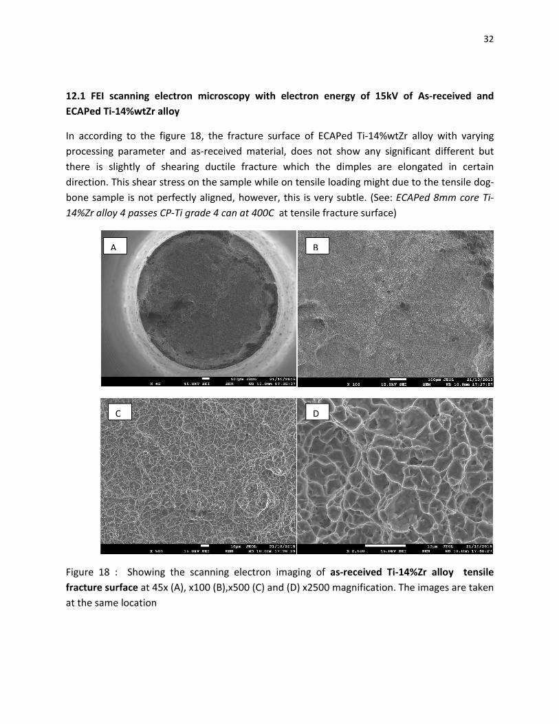
12.1 FEI scanning electron microscopy with electron energy of 15kV of As-received and
ECAPed Ti-14%wtZr alloy
In according to the figure 18, the fracture surface of ECAPed Ti-14%wtZr alloy with varying
processing parameter and as-received material, does not show any significant different but
there is slightly of shearing ductile fracture which the dimples are elongated in certain
direction. This shear stress on the sample while on tensile loading might due to the tensile dog-
bone sample is not perfectly aligned, however, this is very subtle. (See: ECAPed 8mm core Ti-
14%Zr alloy 4 passes CP-Ti grade 4 can at 400C at tensile fracture surface)
Figure 18 : Showing the scanning electron imaging of as-received Ti-14%Zr alloy tensile
fracture surface at 45x (A), x100 (B),x500 (C) and (D) x2500 magnification. The images are taken
at the same location
A B
C D
33
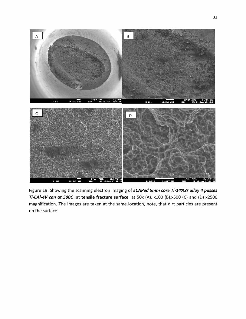
Figure 19: Showing the scanning electron imaging of ECAPed 5mm core Ti-14%Zr alloy 4 passes
Ti-6Al-4V can at 500C at tensile fracture surface at 50x (A), x100 (B),x500 (C) and (D) x2500
magnification. The images are taken at the same location, note, that dirt particles are present
on the surface
A B
C D
34
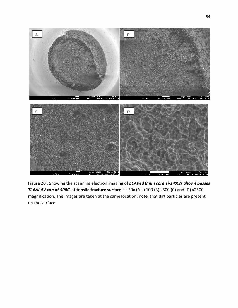
Figure 20 : Showing the scanning electron imaging of ECAPed 8mm core Ti-14%Zr alloy 4 passes
Ti-6Al-4V can at 500C at tensile fracture surface at 50x (A), x100 (B),x500 (C) and (D) x2500
magnification. The images are taken at the same location, note, that dirt particles are present
on the surface
A B
C D
35
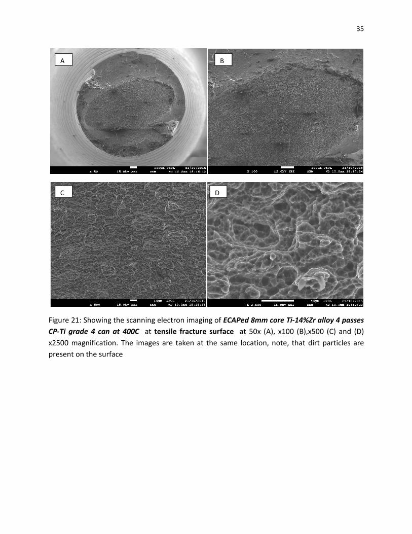
Figure 21: Showing the scanning electron imaging of ECAPed 8mm core Ti-14%Zr alloy 4 passes
CP-Ti grade 4 can at 400C at tensile fracture surface at 50x (A), x100 (B),x500 (C) and (D)
x2500 magnification. The images are taken at the same location, note, that dirt particles are
present on the surface
A B
C D
36
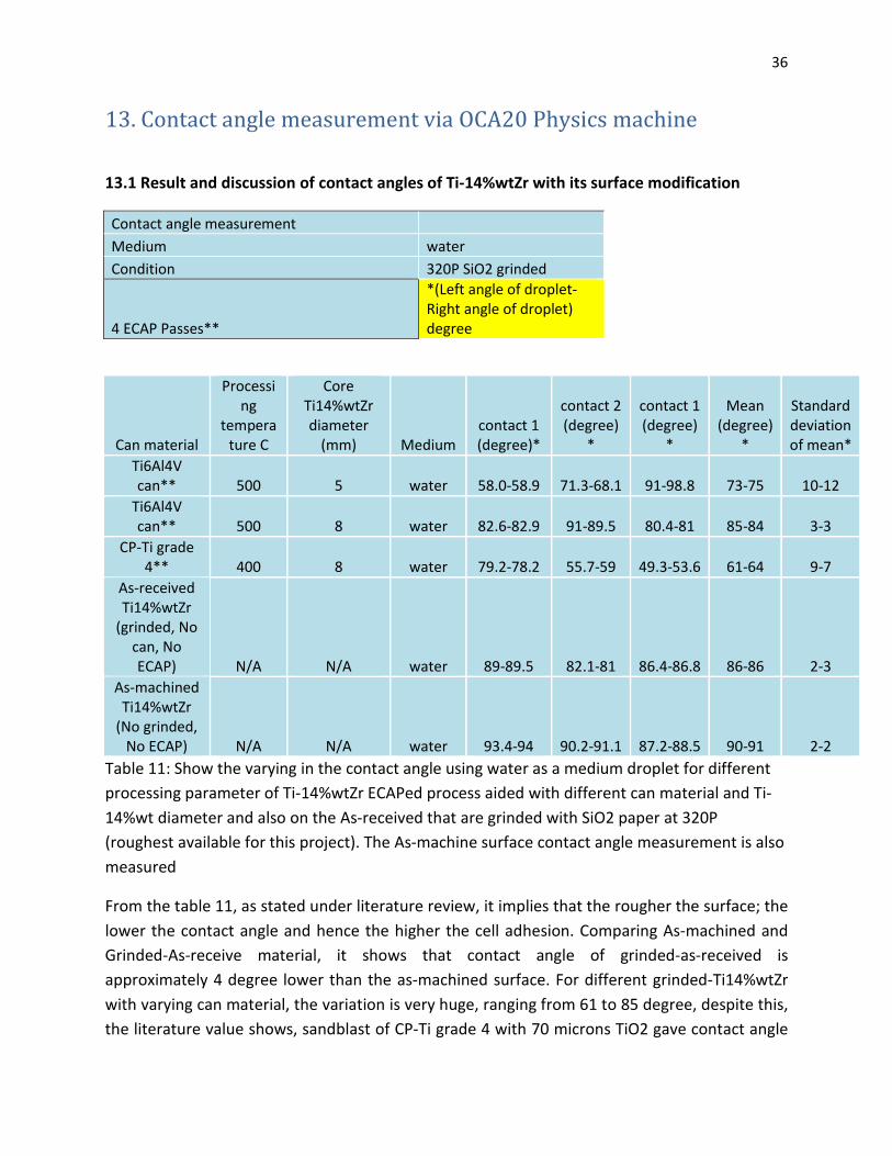
13. Contact angle measurement via OCA20 Physics machine
13.1 Result and discussion of contact angles of Ti-14%wtZr with its surface modification
Contact angle measurement
Medium water
Condition 320P SiO2 grinded
4 ECAP Passes**
*(Left angle of droplet-Right angle of droplet) degree
Can material
Processing
temperature C
Core Ti14%wtZr diameter
(mm) Medium contact 1 (degree)*
contact 2 (degree)
*
contact 1 (degree)
*
Mean (degree)
*
Standard deviation of mean*
Ti6Al4V can** 500 5 water 58.0-58.9 71.3-68.1 91-98.8 73-75 10-12
Ti6Al4V can** 500 8 water 82.6-82.9 91-89.5 80.4-81 85-84 3-3
CP-Ti grade 4** 400 8 water 79.2-78.2 55.7-59 49.3-53.6 61-64 9-7
As-received Ti14%wtZr
(grinded, No can, No ECAP) N/A N/A water 89-89.5 82.1-81 86.4-86.8 86-86 2-3
As-machined Ti14%wtZr
(No grinded, No ECAP) N/A N/A water 93.4-94 90.2-91.1 87.2-88.5 90-91 2-2
Table 11: Show the varying in the contact angle using water as a medium droplet for different
processing parameter of Ti-14%wtZr ECAPed process aided with different can material and Ti-
14%wt diameter and also on the As-received that are grinded with SiO2 paper at 320P
(roughest available for this project). The As-machine surface contact angle measurement is also
measured
From the table 11, as stated under literature review, it implies that the rougher the surface; the
lower the contact angle and hence the higher the cell adhesion. Comparing As-machined and
Grinded-As-receive material, it shows that contact angle of grinded-as-received is
approximately 4 degree lower than the as-machined surface. For different grinded-Ti14%wtZr
with varying can material, the variation is very huge, ranging from 61 to 85 degree, despite this,
the literature value shows, sandblast of CP-Ti grade 4 with 70 microns TiO2 gave contact angle
of 79.86±4.85 degree with cell removal torque of 72.15
expected that removal torque required due to cell adhesion on Ti
Note that, this area is outside scope of project but is done for comparison purpose and
quantitative analysis.
14. Transmission electron microsco
Ti-14%wtZr and ECAPed
As it has been concluded in the earlier Scanning electron microscopy imaging, the different can
material used in ECAP processing of Ti
the ECAP processing itself, however, the temperature
did affect the microstructure of Ti
14.1 Transmission electron microscopy (TEM) result and discussion
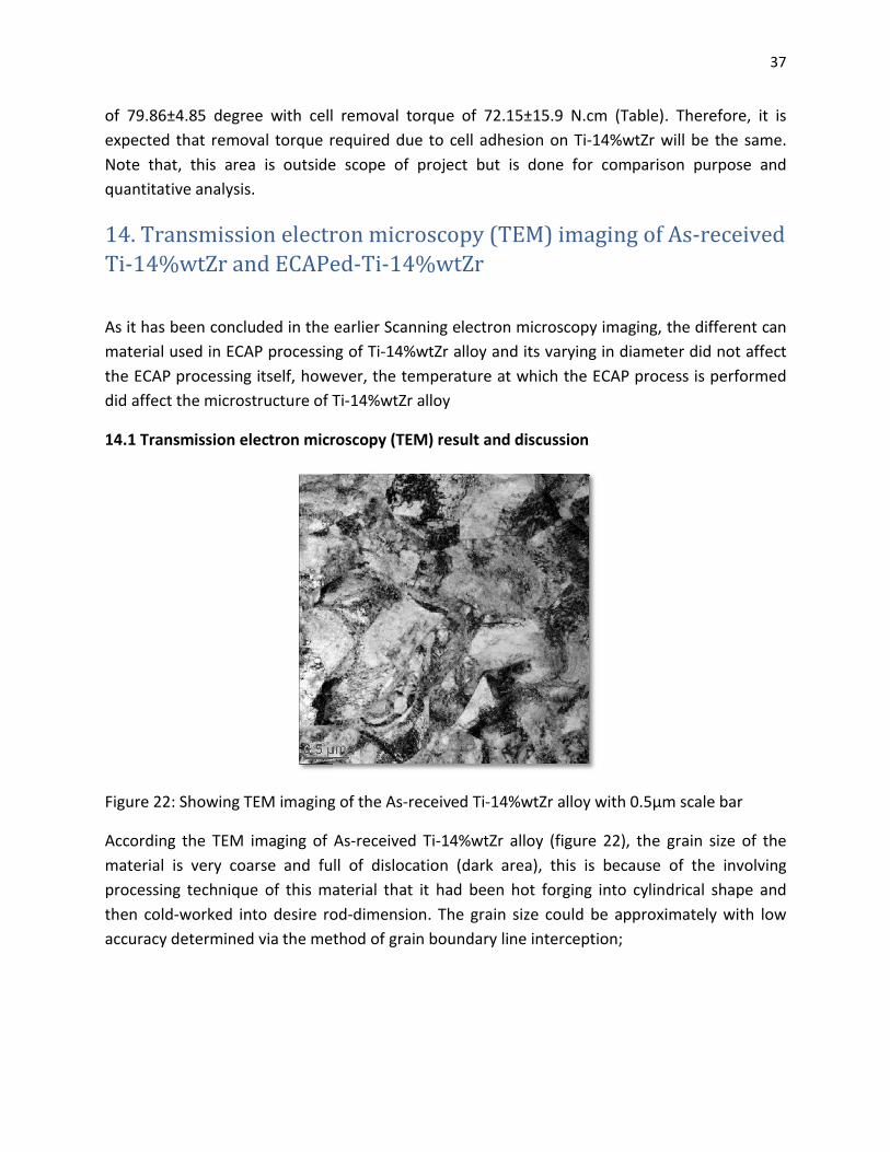
Figure 22: Showing TEM imaging of the
According the TEM imaging of As
material is very coarse and full of dislocation (dark area), this is because of the involving
processing technique of this material that it had been hot forging into cylindrical shape and
then cold-worked into desire rod
accuracy determined via the method of grain bounda
4.85 degree with cell removal torque of 72.15±15.9 N.cm (Table). Therefore, it is
expected that removal torque required due to cell adhesion on Ti-14%wtZr will be the same.
Note that, this area is outside scope of project but is done for comparison purpose and
Transmission electron microscopy (TEM) imaging of As
14%wtZr and ECAPed-Ti-14%wtZr
As it has been concluded in the earlier Scanning electron microscopy imaging, the different can
material used in ECAP processing of Ti-14%wtZr alloy and its varying in diameter did not affe
the ECAP processing itself, however, the temperature at which the ECAP process is performed
did affect the microstructure of Ti-14%wtZr alloy
.1 Transmission electron microscopy (TEM) result and discussion
: Showing TEM imaging of the As-received Ti-14%wtZr alloy with 0.5μm scale bar
According the TEM imaging of As-received Ti-14%wtZr alloy (figure 22), the grain size of the
material is very coarse and full of dislocation (dark area), this is because of the involving
e of this material that it had been hot forging into cylindrical shape and
worked into desire rod-dimension. The grain size could be approximately with low
accuracy determined via the method of grain boundary line interception;
37
. Therefore, it is
14%wtZr will be the same.
Note that, this area is outside scope of project but is done for comparison purpose and
imaging of As-received
As it has been concluded in the earlier Scanning electron microscopy imaging, the different can
14%wtZr alloy and its varying in diameter did not affect
at which the ECAP process is performed
14%wtZr alloy with 0.5μm scale bar
, the grain size of the
material is very coarse and full of dislocation (dark area), this is because of the involving
e of this material that it had been hot forging into cylindrical shape and
dimension. The grain size could be approximately with low
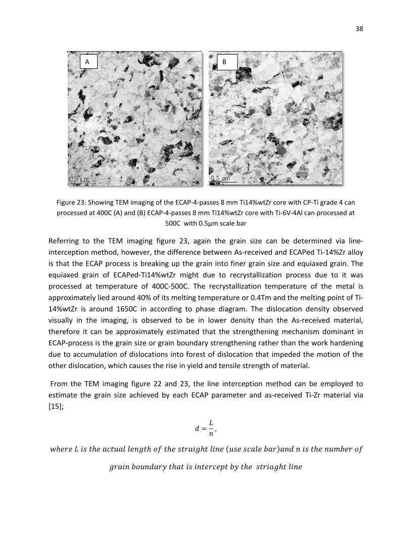
Figure 23: Showing TEM imaging of the ECAP
processed at 400C (A) and (B) ECAP
Referring to the TEM imaging
interception method, however, the difference between As
is that the ECAP process is breaking up the grain into finer grain size and equiaxed
equiaxed grain of ECAPed-Ti14%wtZr might due to recrystallization process due to it was
processed at temperature of 400C
approximately lied around 40% of its melting temperature or 0.4Tm and the melting point of Ti
14%wtZr is around 1650C in according to phase diagram. The dislocation density observed
visually in the imaging, is observed to be in lower density than the As
therefore it can be approximately estimated that the strengthening mechanism domi
ECAP-process is the grain size or grain boundary strengthening rather than the work hardening
due to accumulation of dislocations into forest of dislocation that impeded the motion of the
other dislocation, which causes the rise in yield an
From the TEM imaging figure 22 and 23
estimate the grain size achieved by each ECAP parameter and as
[15];
�ℎ�������ℎ������������ℎ��
�������������
A
Showing TEM imaging of the ECAP-4-passes 8 mm Ti14%wtZr core with CP
ECAP-4-passes 8 mm Ti14%wtZr core with Ti-6V-4Al can processed at
500C with 0.5μm scale bar
Referring to the TEM imaging figure 23, again the grain size can be determined via line
interception method, however, the difference between As-received and ECAPed Ti
is that the ECAP process is breaking up the grain into finer grain size and equiaxed
Ti14%wtZr might due to recrystallization process due to it was
processed at temperature of 400C-500C. The recrystallization temperature of the metal is
approximately lied around 40% of its melting temperature or 0.4Tm and the melting point of Ti
tZr is around 1650C in according to phase diagram. The dislocation density observed
visually in the imaging, is observed to be in lower density than the As-received material,
therefore it can be approximately estimated that the strengthening mechanism domi
process is the grain size or grain boundary strengthening rather than the work hardening
due to accumulation of dislocations into forest of dislocation that impeded the motion of the
other dislocation, which causes the rise in yield and tensile strength of material.
figure 22 and 23, the line interception method can be employed to
estimate the grain size achieved by each ECAP parameter and as-received Ti
� =�
�,
���ℎ�������ℎ�����(�����������)������
���������ℎ����������������ℎ�������ℎ�����
B
38
CP-Ti grade 4 can
4Al can processed at
, again the grain size can be determined via line-
received and ECAPed Ti-14%Zr alloy
is that the ECAP process is breaking up the grain into finer grain size and equiaxed grain. The
Ti14%wtZr might due to recrystallization process due to it was
500C. The recrystallization temperature of the metal is
approximately lied around 40% of its melting temperature or 0.4Tm and the melting point of Ti-
tZr is around 1650C in according to phase diagram. The dislocation density observed
received material,
therefore it can be approximately estimated that the strengthening mechanism dominant in
process is the grain size or grain boundary strengthening rather than the work hardening
due to accumulation of dislocations into forest of dislocation that impeded the motion of the
e strength of material.
, the line interception method can be employed to
received Ti-Zr material via
���ℎ���������
39
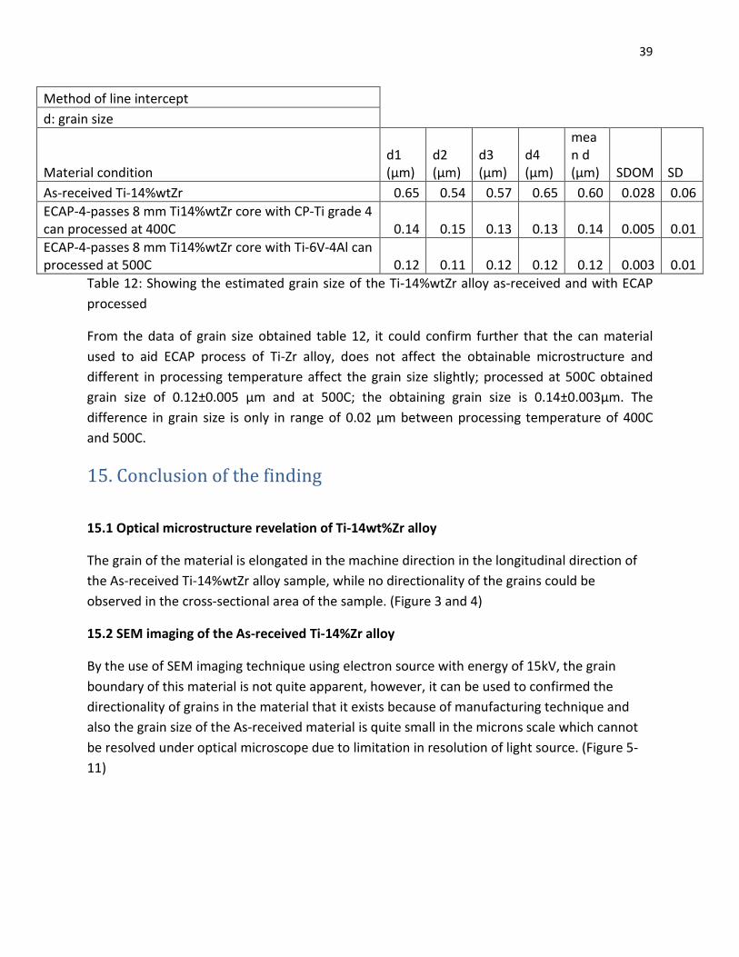
Method of line intercept
d: grain size
Material condition d1 (μm)
d2 (μm)
d3 (μm)
d4 (μm)
mean d (μm) SDOM SD
As-received Ti-14%wtZr 0.65 0.54 0.57 0.65 0.60 0.028 0.06
ECAP-4-passes 8 mm Ti14%wtZr core with CP-Ti grade 4 can processed at 400C 0.14 0.15 0.13 0.13 0.14 0.005 0.01
ECAP-4-passes 8 mm Ti14%wtZr core with Ti-6V-4Al can processed at 500C 0.12 0.11 0.12 0.12 0.12 0.003 0.01
Table 12: Showing the estimated grain size of the Ti-14%wtZr alloy as-received and with ECAP
processed
From the data of grain size obtained table 12, it could confirm further that the can material
used to aid ECAP process of Ti-Zr alloy, does not affect the obtainable microstructure and
different in processing temperature affect the grain size slightly; processed at 500C obtained
grain size of 0.12±0.005 μm and at 500C; the obtaining grain size is 0.14±0.003μm. The
difference in grain size is only in range of 0.02 μm between processing temperature of 400C
and 500C.
15. Conclusion of the finding
15.1 Optical microstructure revelation of Ti-14wt%Zr alloy
The grain of the material is elongated in the machine direction in the longitudinal direction of
the As-received Ti-14%wtZr alloy sample, while no directionality of the grains could be
observed in the cross-sectional area of the sample. (Figure 3 and 4)
15.2 SEM imaging of the As-received Ti-14%Zr alloy
By the use of SEM imaging technique using electron source with energy of 15kV, the grain
boundary of this material is not quite apparent, however, it can be used to confirmed the
directionality of grains in the material that it exists because of manufacturing technique and
also the grain size of the As-received material is quite small in the microns scale which cannot
be resolved under optical microscope due to limitation in resolution of light source. (Figure 5-
11)
40
15.3 Investigation on whether different can material used during ECAP processing will affect
microstructure of ECAP processed Ti-14%wtZr in cross-sectional and longitudinal direction
and Comparing how different can material affect the microstructure of ECAPed Ti-14%wtZr
alloy
It is found that with the aid of Ti6Al4V can material that is used in ECAP processing technique
with different core TiZr alloy 5mm and 8mm diameter and processing temperature of 500C, it
didn’t affect the Ti-14%wtZr alloy that is located in the core, indicating by the microstructure
using SEM imaging technique shown a clear phase separation between Ti6Al4V and Ti14%wtZr
alloy. The two materials of Ti-14%wtZr and Ti6Al4V are immiscible to each other. With the
different in diameter of 8mm and 5mm core Ti-Zr alloy in Ti6Al4V can, the microstructure
exhibit equiaxed grain morphology.
But with processing at lower temperature of 400C with pure titanium grade 4 can material and
8mm diameter core Ti-14%wtZr, the shear band and micro-crack are formed within the Ti-
14%Zr alloy, this might due to processing at 400C induced some part of the TiZr alloy to
recovery and recrystallization and so this area will have lower dislocation density and its
strength comparing to the rest of the area is lower, hence this region deforms more during
ECAP which resulting in shear band forming and micro-cracks. The region of shear band and
micro-crack is not desire due to it could act as fracture site upon deformation. In addition, there
is no clear phase separation between the CP-Ti grade 4 can and Ti-14%wtZr. The CP-Ti grade 4
and Ti-14%wtZr has the same alpha-phase, which might be miscible at the edge of the
specimen but this will not affect the tensile testing result if dog-bone sample because sample
will be machine down till its reach the core, which is only Ti-14%wtZr is there.
15.4 Investigation on the mechanical properties of As-Received Ti-14%Zr alloy
Both the actual tensile testing and microhardness testing HV of Ti-14wt%Zr and CP-grade 4 Ti
are explored and compared. From micro-hardness value HV , there is a correlation that 3 times
yield strength of material is generally equal to hardness HV of the material.
The resulting yield strength from the tensile testing, showed no significant different in yield
strength of Ti-14%wtZr from CP-Ti grade 4; σy 0.2%(Ti14%wtZr) = 620 MPa and σy 0.2%(CP-Ti-
grade 4) = 600MPa. However, the ultimate tensile strength are huge different with 970MPa and
770MPa for Ti-Zr and CP-Ti. Therefore, it is indicating that Zr give improvement in strain
hardening rate by limiting dynamic recovery during tensile deformation. However, elongation
of TiZr alloy is poor compare to CP-Ti grade 4 (Table).
On the contrary, yield strength from correlation of hardness and yield of material is
contradicting in as-received Ti14%wtZr with the actual tensile test, where yield strength
41
obtained from correlation is approximately ~940MPa while from tensile test, yield strength is
only 620MPa. The cause of this need to be subjected to further investigation.
15.5 Tensile facture surface analysis of As-received and 4 ECAP Passes at temperature of 500C
and 400C with varying in can-aided ECAP material of Titanium Zirconium alloys
Both of as-received and ECAP Titanium zirconium alloy show ductile characteristic with lots of
tensile dimples formation at the fracture surface with also little shearing dimples surface, which
indicate that sample was also subjected to minor shear stress during uniaxial tensile testing.
15.6 Contact angle measurement via OCA20 Physics machine
Sandblast of CP-Ti grade 4 with 70 microns TiO2 gave contact angle of 79.86±4.85 degree with
cell removal torque of 72.15±15.9 N.cm. For different grinded 320P SiO2-Ti14%wtZr with
varying can material, the variation is very huge, ranging from 61 to 85 degree. But the expected
cell adhesion will be the same as Ti14%wtZr has the same alpha phase with CP-Ti grade 4.
15.7 Transmission electron microscopy (TEM) imaging of As-received Ti-14%wtZr and ECAPed-
Ti-14%wtZr
The microstructure of as As-received Ti-14%wtZr and ECAPed-Ti-14%wtZr are reviewed As-
received Ti-14%wtZr show high density of dislocation while ECAPed-Ti-14%wtZr showed
equiaxed grains morphology, the reason for this because of physically breaking up of grains via
ECAP processing and grain recovery and recrystallization that occur at elevated temperature of
~400C to 500C to achieve this equiaxed grain morphology. The grain size is also determined via
line-interception method to be around 0.60±0.06 μm and ECAPed- Ti-14%wtZr around ~ 0.12 to
0.14 μm
42
16. Recommendation for future work and Evaluation of the project
Repeat the tensile testing of Ti-14%wtZr alloy with larger dog bone sample in according
to ASTM standard E8, such that the extensometer could be used to measure and
determine more accurate extension, since the current calculated strain is inaccurate and
give young modulus of ~22GPa for Ti14%wtZr alloy, but the literature value is expected
to be around 104GPa [16].
To do tensile testing of ECAPed Ti-14%wtZr alloy; cause there is a problem with the
ECAP die throughout the semester, only broken piece of ECAP sample could be taken
and determined its strength via hardness and yield strength correlation. Actual tensile
testing would provide better understanding of its mechanical properties with proper
equipped extensometer.
To investigate wider temperature range of ECAP-processing temperature and the
obtainable microstructure, since at 400C ECAP, shear band is found within the structure
of Ti-14%wtZr alloy therefore what will happen, for instance, if it was done at 450C and
even higher or closed to Ti-beta phase transformation temperature ( in according to Ti-
Zr binary phase diagram). Furthermore, to obtain the preferable low best ECAP-
temperature that give highest strength, highest ductility and for cost-saving in term of
affordability.
Exploring martensitic alpha’ phase of Ti-Zr alloy, which it is said to be the phase
responsible for increasing in ductility of ECAPed Ti-14%wtZr during ECAP processing, for
instance, could the alpha’ martensitic phase be formed with just only control cooling
rate and annealing and therefore the Ti-14%wtZr alloy could subject to higher ECAP
passes due to the increase in ductility
To explore the number of ECAP passes until the smaller grain size of material could no
longer give grain boundary strengthening effect, however this will depend on ductility
of the material as higher strain the material is subjected to, its strain history might end
up corresponding to strain at which necking occur and strain further the material could
fracture
43
17. Acknowledgement
Special thanks to Institut Straumann AG (Public) that provide the patented Ti-14%wtZr alloy
material to be used and studied in this investigation
Alexander Medvedev for helping with taking pictures of scanning electron microscopy of
Ti14%wtZr microstructure with different processing variables , which are “As-received Ti-
14%wtZr, ECAPed 5mm core Ti-14%Zr alloy 4 passes Ti-6Al-4V can at 500C”, “ECAPed 8mm core
Ti-14%Zr alloy 4 passes Ti-6Al-4V can at 500C” and “ECAPed 5mm core Ti-14%Zr alloy 4 passes
CP-Ti grade 4 can at 400C”. And help with tensile testing of CP-Ti grade 4 and As-received Ti-
14%wtZr
Yuanshen Qi for helping with taking pictures of scanning electron microscopy of tensile fracture
surface of “As-received Ti-14%wtZr, ECAPed 5mm core Ti-14%Zr alloy 4 passes Ti-6Al-4V can at
500C”, “ECAPed 8mm core Ti-14%Zr alloy 4 passes Ti-6Al-4V can at 500C” and “ECAPed 5mm
core Ti-14%Zr alloy 4 passes CP-Ti grade 4 can at 400C”.
18. References
[1]Mitsuo Niinomi,Masaaki,Junko Hieda, “Development of new metallic alloys for biomedical
applications”,Acta Biomaterialia 8 (2012), pp.3888-3903, 15th July 2012
[2]H.Michelle Grandin, Simon Berner and Michel Dard, “A review of titanium zirconium (TiZr)
alloys for use in endosseous dental implant, Material 2012, 5, pp.1348-1360, 13th August 2012
[3] H.Michelle Grandin, Simon Berner and Michel Dard, “A review of titanium zirconium (TiZr)
alloys for use in endosseous dental implant, Material 2012, 5, pp.1348-1360, 13th August 2012
[4] Fabio B.Vincente, Diego R.N.Correa, Tatiani A.G.Donato, Victor E.Arana-Chavezz, Marilia
A.R.Buzalaf and Carlos R,Grandini, “The influence of small Quantities of oxygen in the structure,
microstructure, hardness, elasticity modulus and cytocompatibility of Ti-Zr alloys for dental
applications”, Material 2014,7,pp.542-553, 20th January 2014
[5] H.Michelle Grandin, Simon Berner and Michel Dard, “A review of titanium zirconium (TiZr)
alloys for use in endosseous dental implant, Material 2012, 5, pp.1348-1360, 13th August 2012
[6] Ruslan Z.Valiev, Yuri Estrin,Zenji Horita,Terence G.Langdon, Michael J. Zehetbauer, and
Yuntian T.Zhu, Journal of Material (JOM), April 2006
44
[7] Zhibo Zhang, Ming Li,Defeng Guo, Yingdong Shi,Xiangyi Zhang, Hans-Eckhardt
Schaefer,Science Direct, Materials Science & Engineering A 594 (2014) 321-323, 4th December
2013 Enchanment of TiZr ductility by hcp-fcc martensitic transformation after severe plastic
deformation
[8]Carlos Nelson Elias, Yoshiki Oshida, José Henrique Cavalcanti Lima,Carlos Alberto Muller,
“Relationship between surface properties (roughness, wettability and morphology) of titanium
and dental implant removal torque”, JOURNAL OF THE MECHANICAL BEHAVIOR OF
BIOMEDICAL MATERIALS, 1234 – 242,(2008), doi:10.1016/j.jmbbm.2007.12.002
[9] OBSERVATION OF AN ADIABATIC SHEAR BAND IN TTTANTUM BY HIGH-VOLTAGE TRANSMISSION ELECTRON MTCROSCOPY M. A. ~EYERS~ and FAN-RYONG PAK Arlu nrrfall. Vol. 34. No. 12, pp. 2493-2499,1986 [10] M.A. Meyers a,, G. Subhash b, B.K. Kad a, L. Prasad Evolution of microstructure and shear-band formation in α-hcp titanium Mechanics of Materials 17 (1994) 175-193 [11] Samuel Steinemann, US Patent 8,168,012 B2, 2012 May 1
[12] J. L. Murray, Bulletin of Alloy Phase Diagrams Vol. 2, No. 2, 1981
[13] J.R.Cahoon,W.H.Broughton,A.R.Kutzak Metallurgical Transactions, vol.2,issue 7,pp.1979-
1983, July 1971
[14] R.W. Hertzberg, R.P.Vinci, J.L.Hertzberg, “Fracture: Overview”, in Deformation and Fracture
Mechanics of engineering materials 5th edition, John Wiley & Sons, Inc.,2013, chapter 5,
section 5.9.1, pg. 280.
[15] Michigan Technological University. Grain Size (method of line interception). [Online].
Available: http://www.mse.mtu.edu/~drjohn/my3200/lab1/grainsize.html
[16] D.R.N. Correa, F.B. Vicente, T.A.G. Donato, V.E. Arana-Chavez, M.A.R. Buzalaf, C.R. Grandini, The effect of the solute on the structure, selected mechanical properties, and biocompatibility of Ti–Zr system alloys for dental applications, Materials Science and Engineering: C, Volume 34, 1 January 2014, Pages 354-359, ISSN 0928-4931, http://dx.doi.org/10.1016/j.msec.2013.09.032.
[17] M. Arulselv and G. Ganesan, “A Study on Compression Test on Ti-6Al-4V in Various Strain
Rates and Various Temperatures”, International Journal of Recent Technology and Engineering
(IJRTE) ISSN: 2277-3878,Volume-2, Issue-4, September 2013. [Online]. Available:
http://www.ijrte.org/attachments/File/v2i4/D0777092413.pdf

45