Embed Size (px)
Citation preview
Novel Electrophotographic Toners for Providing Metallic Effects Dinesh Tyagi, Louise Granica and Kevin Lofftus; Eastman Kodak Company, Rochester, NY, USA.
Abstract In order to produce toners that are capable of providing
metallic sparkle and effect, a number of obstacles have to be first overcome. Since having static charge is an important requirement for toners, it is not practical to use conductive metal flakes in metallic toner formulations. This difficulty was overcome by using mica or similarly based interference pigments. These non-conductive pigments not only provide a large flat reflective surface but can be coated with inorganic and organic coatings. By controlling the thickness of the high refractive index inorganic coating over the mica flakes, the color of the reflected light changed and can be utilized to enhance the metallic sparkle.
These toners can be produced by minimizing the shear conditions in the extruder during the compounding of the toner components. These can be created by optimizing the compounding temperature, screw configurations, molecular weight of the toner resin etc. By imposing a convergence on the toner melt at the die exit and by controlling the draw ratio of the melt slab after the die exit, the pigment flakes can be forced to align in the process direction. The resulting toners have a flat shape as a consequence of the internal structure formed during the melt processing step.
Due to the large size of the pigment flakes in the finished toner, and its shape, these toners are capable of providing remarkable sparkle and metallic effects. These toners produce the metallic effect by themselves but alternatively they can be placed over or under other color toners to generate many interesting effects that were not possible before. A method of measuring the sparkle in metallic images is also described. By measuring color properties at various angles, “Flop Index” can be calculated and used to quantify the extent of metallic effect.
Introduction Over the years, many attempts have been made to print
metallic effects using dry electrophotographic toners. But despite many attempts to produce metallic toners in the past, most of these efforts have not been succesful. Several disclosure have been made describing different methods of producing metallic toners in which the metal flakes have been first treated and used as pigment flakes [1]. In another disclosure, the treated metal oxides particles are attached to the outside surface of the toner in a separate processing step [2]. Most of these attempts have only provided insufficient metallic effects. So there is still an existing and unfulfilled need to produce toners that are capable of producing metallic appearance or sparkle.
In order to produce a toner that is capable of producing metallic effects, there are several hurdles that need to be overcome. These include:
• Electrical conductivity of pigment • Size of pigment • Reflecting surfaces/planes in pigment flake
• Orientation of pigments • Manufacturing process to produce such toners
In order for a toner to function properly in an electrophotographic process, it has to be able to sustain an electrical charge for development and transfer etc. Metallic flakes can perform well in inks but when these flat flakes are used as pigments in toner, the electrical conductivity of such pigments becomes an issue. To overcome this difficulty the metal flakes are often coated with a non-conducting inorganic coating or an organic polymer resin. These attempts to coat the metal flakes, however, is only able to provide marginal benefits. Most of the metal pigments flakes are not mechanically strong and readily break-up during the manufacturing process. As pigment fractures, it exposes the conductive core which immediately affects the toner charge. Also, some coatings, especially polymeric types, can separate from the surface as a result of the elevated temperatures necessary in the melt compounding processes used in toner manufacturing. Any exposed surface of a conductive metal flake can not only reduce the charge of the toner, they can often cause charge injection when exposed to high electrical fields. A metallic toner that exhibits adequate charge/mass, may become conductive when present in the high electric fields that are encountered during a converging nip transfer.
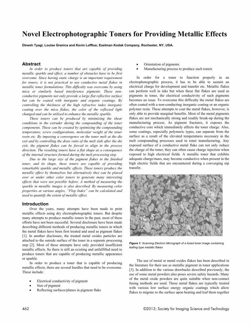
Figure 1: Scanning Electron Micrograph of a fused toner image containing leafing type metallic flakes
The use of metal or metal oxides flakes has been described in the literature for their use as metallic pigment in toner applications [3]. In addition to the various drawbacks described previously, the use of some metal powders also poses severe safety hazards. Many of the metal oxide powders are quite suitable when non-contact fusing methods are used. These metal flakes are typically treated with various low surface energy organic coatings which allow flakes to migrate to the surface upon heating and leaf them together
462 ©2013; Society for Imaging Science and Technology
as
chof
pinaewtodpw
Fp
inlalafhsT4mato
P
imDmpisbth
as shown in Figusuch formulation
In order toconductivities, phave been descrother flat surfacefor toner capable
The metallipigment flakes encreases, the re
also increases. Texceed 500 micrwould be impossoners. Over the
down because oproduce toners wwith the image qu
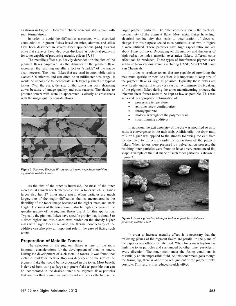
Figure 2: Scanning pigment for metallic
As the sizencreases at a muarger also has arger, one of t
fixability of the theight. The massspecific gravity Typically the pig4 times higher anmass with largeradditive can alsooners.
PreparationThe selecti
mportant considDuring the develmetallic sparkle pigment flake thas derived from u
be incorporated hat are less than
ure 1. However,ns. avoid the diff
pigment flakes bribed in severales have also beee of producing mc effect also heaemployed. As thesulting metallicThe metal flakes rons and can oftsible to incorpore years, the sizeof image qualitywith metallic apuality considera
g Electron Micrograpc toners.
e of the toner isuch accelerated c27 times more
the major diffictoner image becs of the toner wof the pigment
gment flakes havnd thus places er toner size. Also play an import
n of Metallicon of the pigm
derations for thelopment of suchor metallic flopat could be incousing as large a in the desired t
n 5 microns wer
, charge concern
ficulties associatbased on mica, toner applicatien disclosed as
metallic effects [7avily dependenthe diameter of
c effect or “sparthat are used in
ften be in millimrate such larger pe of the toners hy and cost reasoppearance is cletions.
ph of treated mica
s increased, the cubic rate. A ton
mass. When pculties that is ecause of the highould also be higflakes useful fo
ve specific gravitextra burden on so, the thermal ctant role in the e
c Toners ment flakes is e development h metallic tonersp was dependentorporated in the t
pigment flake atoner size. Pigmre found not be
ns still remain w
ted with electrialumina and silions [4-6]. Sevepotential pigme
7, 8] t on the size of the pigment fla
rkle” of the iman automobile paimeter size rangepigments in typihas been shrinkons. The desirearly at cross-roa
flakes useful as
mass of the toner which is 3 timparticles are muencountered is her mass and stagher because of or this applicatity that is about 3the already hig
conductivity of ease of fixing su
one of the mof metallic tone
s, it was found tt on the size of toner. Most beneas possible that c
ment flake particas effective as
with
ical lica eral ents
the ake age ints e. It ical ing
e to ads
ner mes uch the ack the on.
3 to her the uch
most ers. that the efit can cles the
larger pconductelectricacharge. 2 were about 1 high refeffect caavailablSun Che
In maximuthe pigmvery fraof the pinherentachieved
•••••
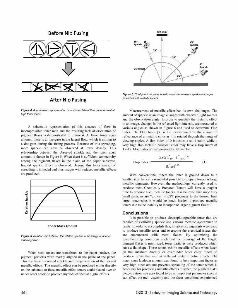
In acause a of 2 or the die flakes. Wresultingshape. EFigure 3
Figure 3:producing
In reflectinthe papehigh, theevery dessentiathe fusinpossible
pigment particlestivity of the pigal conductivity For this purposeutilized. Thesemicron thick. D
fractive index man be producede from various semicals. order to produc
um sparkle or mement flake as lagile and can frac
pigment flakes dt shear forces ned by appropriate
processing temextruder screwthroughput ratmolecular weishear thinning
addition, the exiconvergence in higher was appface to further
When toners weg toner particlesExample of the f3.
: Scanning Electrong metallic effect
order to increang planes of the er or any other se toner particles
direction. The toally an incompreng nip, there is ae. This results in
s. The other congment flake. Mo
that leads to e coated mica p
e particles have Depending on thmaterial over m. These types osources includin
ce toners that aretallic effect, it
arge as possible.cture very easily
during the toner eed to be kept ae optimization ofmperature w configuration te ight of the polymg additives
it geometry of ththe melt slab. A
plied to the stranr intensify the ere prepared by were found to h
flat shape of such
n Micrograph of ton
se metallic effepigment flakes
substrate used. Ws and surroundedoner melt undessible fluid. As talmost no realiga reduced spark
nsideration is thost metal flakesdeterioration o
articles, as showhigh aspect ra
he number and tmica flakes, difff interference p
ng BASF, Merck
re capable of pris important to k. Typically thesy. To minimize t
manufacturing ps low as possiblf:
mer resin
he die was modifAdditionally, thends following thorientation of t
y pulverization phave a very pronh toner particles
ner particles suitabl
ect, it is necessaare parallel to t
When toner massd by other tonerer the fusing cothis toner mass g
gnment of the pikle effect.
he electrical s have high of electrical wn in Figure atio and are thickness of
fferent color pigments are k/EMD, and
roviding the keep size of e flakes are
the breakage process, the le. This was
fied so as to e draw ratio he exit from the pigment process, the nounced flat is shown in
le for
ary that the the plane of s laydown is r particles in onditions is goes though gment flake
NIP 29 and Digital Fabrication 2013 463
Fh
inpaamraahsa
Fm
pTmou
Figure 4: A schemahigh toner mass.
A schematncompressible t
pigment flakes iamount, there is a dot gain durinmore sparkle celationship betw
amount is shownamong the pigmhighest sparkle spreading is impeare produced.
Figure 5: Relationsmass laydown.
When such pigment particleThis results in inmetallic effects. on the substrate ounder other color
Rela
tive
Spa
rkle
atic representation
tic representatiotoner melt and ts demonstrated an increase in th
ng the fusing prcan now be oween the obsern in Figure 5. Wment flakes in teffect is observeded and thus im
ship between the re
toners are trans were mostly ancreased sparkleThe metallic effor these metallicrs to produce my
Toner Mass A
of restricted lateral
on of this absthe resulting lacin Figure 4. Athe lateral flow, rocess. Because observed at lowrved sparkle an
When there is suffthe plane of thved. Beyond thmages with reduc
elative sparkle in the
nsferred to the aligned in the pe and the generafect can be produc effect toners coyriads of special
Amount
l flow on toner melt
sence of flow k of orientationt lower toner mwhich is similarof this spreadi
wer density. Tnd the toner mficient connectivhe paper substrais toner mass, ced metallic effe
e image and toner
paper surface, plane of the papation of the desiuced either direcould placed overdigital effects.
t at
in n of
mass r to ng,
This mass vity ate, the
ects
the per. red ctly r or
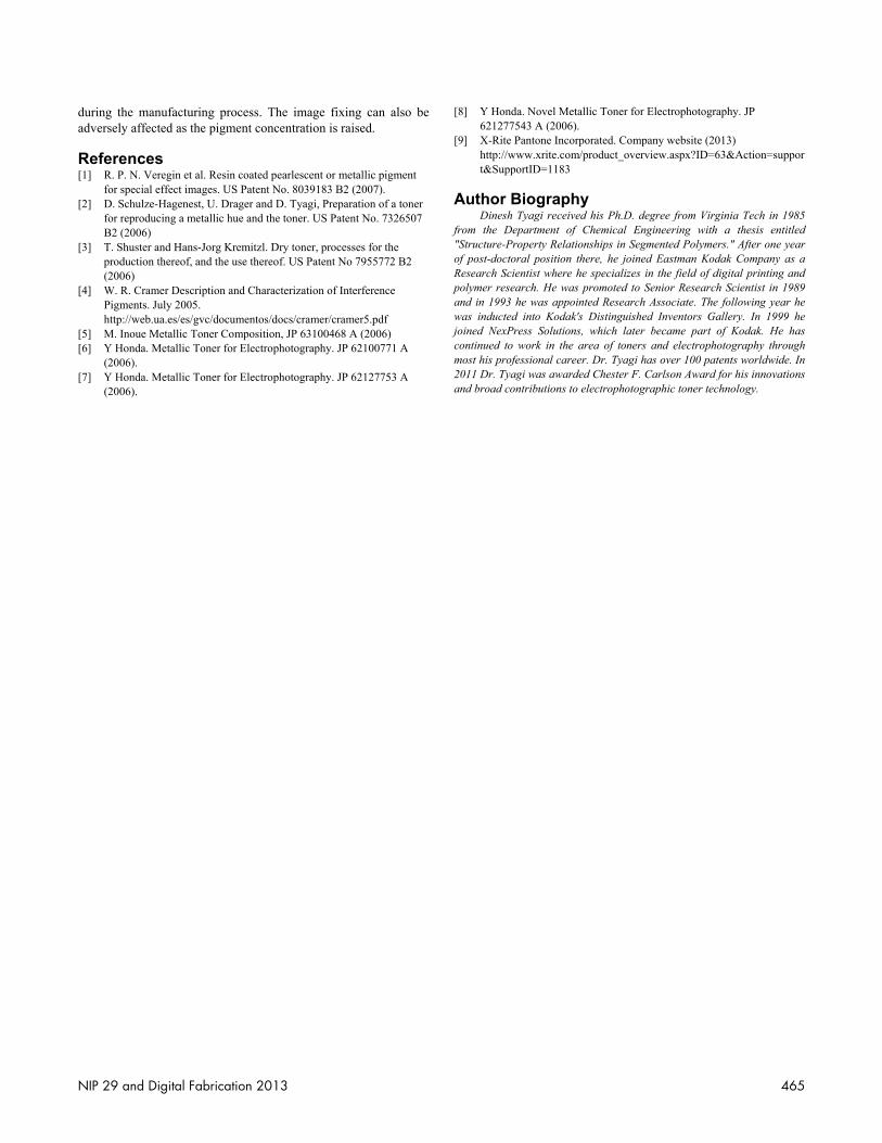
Figure 6:produced
Meamount and the in an imvarious Index. Treflectanviewingvery hig15–17. F
F
Wi
smaller metallicproducetime to small palarger totoners d
ConclIt i
capable prints. Into produare enmanufacpigmenthave a fon the producetoner mvery hignecessarconcentrcan affe
: Configurations usd with metallic toner
easurement of mof sparkle in an observation ang
mage, changes in angles as show
The Flop Index nce of a metallic
g angles. A flop gh flop metallicFlop Index is ma
Flop Index =
ith conventionalsize, hence is so
c pigments. Howe most Chemicaproduce such marticles are “grooner size, it wo
due to the inabilit
lusions is possible to pof exhibiting s
n order to accomuce metallic ton
ncountered witcturing conditiot flakes is minimflat shape. These
substrate direce prints that exhass laydown amgh toner amounry for producingration was also
ect the melt visc
sed in instruments trs.
metallic effect himage changes
gle. In order to the reflected lig
wn in Figure 6 a[9] is the mea
c color as it is rindex of 0 indi
c basecoat colorathematically de
2.69(L*15° - L
(L*
45°)0.86
l toners the toomewhat possibwever, the methally Prepared T
metallic toners. Itown” in CPT prould be much hty to incorporate
produce electropsparkle and varimplish this, interner and overcomth metal flakons such that thmized, toner parte toners exhibit ctly or over/unhibit different m
mount was foundt prevents sprea
g metallic effectsfound to be an i
cosity and the sh
to measure sparkle
has its own chalwith observer, lquantify the me
ght intensity areand used to deteasurement of therotated through ticates a solid cor may have a flofined by:
L*110°)1.11
6
oner is ground le to prepare ton
hodology currenToners will havet is believed thaocesses to the dharder to produe larger pigment
photographic tonious metallic aprference pigmentme the electricalkes. By optimhe breakage of ticles were prodmetallic effects
nder other colormetallic color e
d to be a importaading of the tons. Further, the piimportant paramhear conditions
e in images
llenges. The ight sources
etallic effect measured at ermine Flop e change in the range of
olor, while a op index of
(1)
down to a ners is large ntly used to e a tpugher at since very desired final uce metallic flakes.
ner that are ppearance to ts were used l issues that mizing the f the fragile duced which
when fused r toners to effects. The ant factor as ner which is igment flake
meter since it experienced
464 ©2013; Society for Imaging Science and Technology
during the manufacturing process. The image fixing can also be adversely affected as the pigment concentration is raised.
References [1] R. P. N. Veregin et al. Resin coated pearlescent or metallic pigment
for special effect images. US Patent No. 8039183 B2 (2007). [2] D. Schulze-Hagenest, U. Drager and D. Tyagi, Preparation of a toner
for reproducing a metallic hue and the toner. US Patent No. 7326507 B2 (2006)
[3] T. Shuster and Hans-Jorg Kremitzl. Dry toner, processes for the production thereof, and the use thereof. US Patent No 7955772 B2 (2006)
[4] W. R. Cramer Description and Characterization of Interference Pigments. July 2005. http://web.ua.es/es/gvc/documentos/docs/cramer/cramer5.pdf
[5] M. Inoue Metallic Toner Composition, JP 63100468 A (2006) [6] Y Honda. Metallic Toner for Electrophotography. JP 62100771 A
(2006). [7] Y Honda. Metallic Toner for Electrophotography. JP 62127753 A
(2006).
[8] Y Honda. Novel Metallic Toner for Electrophotography. JP 621277543 A (2006).
[9] X-Rite Pantone Incorporated. Company website (2013) http://www.xrite.com/product_overview.aspx?ID=63&Action=support&SupportID=1183
Author Biography Dinesh Tyagi received his Ph.D. degree from Virginia Tech in 1985
from the Department of Chemical Engineering with a thesis entitled "Structure-Property Relationships in Segmented Polymers." After one year of post-doctoral position there, he joined Eastman Kodak Company as a Research Scientist where he specializes in the field of digital printing and polymer research. He was promoted to Senior Research Scientist in 1989 and in 1993 he was appointed Research Associate. The following year he was inducted into Kodak's Distinguished Inventors Gallery. In 1999 he joined NexPress Solutions, which later became part of Kodak. He has continued to work in the area of toners and electrophotography through most his professional career. Dr. Tyagi has over 100 patents worldwide. In 2011 Dr. Tyagi was awarded Chester F. Carlson Award for his innovations and broad contributions to electrophotographic toner technology.
NIP 29 and Digital Fabrication 2013 465