Embed Size (px)
Citation preview
Development of Multiple Device CollaborationSystem Using Built-in Camera Image
Kazuki Tada(B) and Jiro Tanaka
University of Tsukuba, Tsukuba, Japan{kazuki,jiro}@iplab.cs.tsukuba.ac.jp
Abstract. In this paper, we introduce a multi-device collaboration sys-tem using the image obtained from the built-in camera. Users can useapplications that utilize multiple devices in cooperation without needingspecial devices such as a touch panel sensor. Our system enables accu-rate position tracking of a smartphone any screen by obtaining an imagefrom the device’s front camera to recognize the device and measure thedevice’s position by template matching [1]. In many multi-device collab-oration approaches, it was necessary to overlap the screens. However, ourproposed method is capable of multi-device collaboration without over-lapping the screens of the devices, and it can be applied using a widerange of off-screens. We implemented some of the applications using thistechnique. In addition, we showed the usefulness of this approach byevaluation experiments.
Keywords: Multiple device · Image processing · Image recognition ·Smartphone · Template matching
1 Introduction
Recently, due to the spread of smartphones and tablet devices, people have cometo possess multiple devices. Multi-device collaboration systems permit users toconnect many different devices and share the content among them. Such systemsare beneficial in improving work efficiency.
Various techniques that recognize different devices collaborating with eachother have been proposed. For example, Yatani et al. and Kamo et al. proposedmethods to recognize other devices by capturing mobile devices equipped witha marker or infrared LED by room camera [1,2]. Furthermore, a method ofoverlaying the mobile devices with a conductive material on the touch screendevice has been proposed [3]. In this method, since the touch point occurs onthe touch screen, the positional relationship between collaborating devices canbe determined.
However, in these techniques, special tools (e.g. a touch screen and infraredLED) are required for the multi-device collaboration. In this study, we haveimplemented a new multi-device collaboration method using a differential imageobtained from the device’s built-in camera. This approach uses only camerasmounted on the device to determine the positional relationship between multipledevices and implement various cooperative operations.c© Springer International Publishing Switzerland 2016M. Kurosu (Ed.): HCI 2016, Part II, LNCS 9732, pp. 419–427, 2016.DOI: 10.1007/978-3-319-39516-6 40
420 K. Tada and J. Tanaka
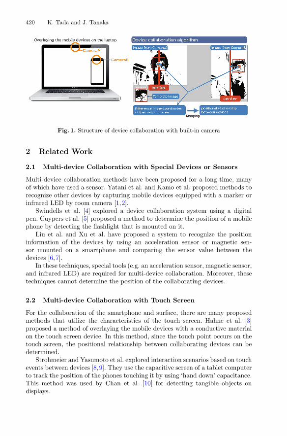
Fig. 1. Structure of device collaboration with built-in camera
2 Related Work
2.1 Multi-device Collaboration with Special Devices or Sensors
Multi-device collaboration methods have been proposed for a long time, manyof which have used a sensor. Yatani et al. and Kamo et al. proposed methods torecognize other devices by capturing mobile devices equipped with a marker orinfrared LED by room camera [1,2].
Swindells et al. [4] explored a device collaboration system using a digitalpen. Cuypers et al. [5] proposed a method to determine the position of a mobilephone by detecting the flashlight that is mounted on it.
Liu et al. and Xu et al. have proposed a system to recognize the positioninformation of the devices by using an acceleration sensor or magnetic sen-sor mounted on a smartphone and comparing the sensor value between thedevices [6,7].
In these techniques, special tools (e.g. an acceleration sensor, magnetic sensor,and infrared LED) are required for multi-device collaboration. Moreover, thesetechniques cannot determine the position of the collaborating devices.
2.2 Multi-device Collaboration with Touch Screen
For the collaboration of the smartphone and surface, there are many proposedmethods that utilize the characteristics of the touch screen. Hahne et al. [3]proposed a method of overlaying the mobile devices with a conductive materialon the touch screen device. In this method, since the touch point occurs on thetouch screen, the positional relationship between collaborating devices can bedetermined.
Strohmeier and Yasumoto et al. explored interaction scenarios based on touchevents between devices [8,9]. They use the capacitive screen of a tablet computerto track the position of the phones touching it by using ‘hand down’ capacitance.This method was used by Chan et al. [10] for detecting tangible objects ondisplays.
Development of Multiple Device Collaboration System 421
2.3 Multi-device Collaboration with Device’s Camera
Several multi-device collaboration methods using a camera have been proposed.Chan et al., Cuypers et al., and Rohs et al. proposed a method for device collab-oration by reading a special pattern projected onto the display by the phone’scamera [11–13].
THAW [14] is a method to overlap the mobile device to the computerscreen. By analyzing the information obtained from the back camera of themobile device, we can determine the positional relationship between collaborat-ing devices. With a multi-device collaboration method using a camera, there is noneed to attach extra equipment, such as additional sensors, to the smartphone.
However, it is necessary to project a special pattern on one of the displays oroverlap the devices. In contrast, our proposed method is capable of collaborationwithout overlapping the screens of the devices, and it can be applied using a widerange of off-screens.
3 System Design
Our method uses an image obtained from the device’s built-in camera to recog-nize the device and measure the device’s position by template matching. Forexample, the collaboration between a personal computer and a smartphone isshown in Fig. 1 (left side). In this case, images of the same target are obtainedwith each of the cameras. A template is dynamically created to form part ofthe image of one camera. Next, our system tries to match this template imagewith images from the other camera. From the difference in the coordinates ofthe matching area, it calculates the positional relationship between the devices,as shown in Fig. 1 (right side).
3.1 System Flow
In this section, the operation of the system in this method will be describedusing a case where a user is linking a smartphone and laptop computer.
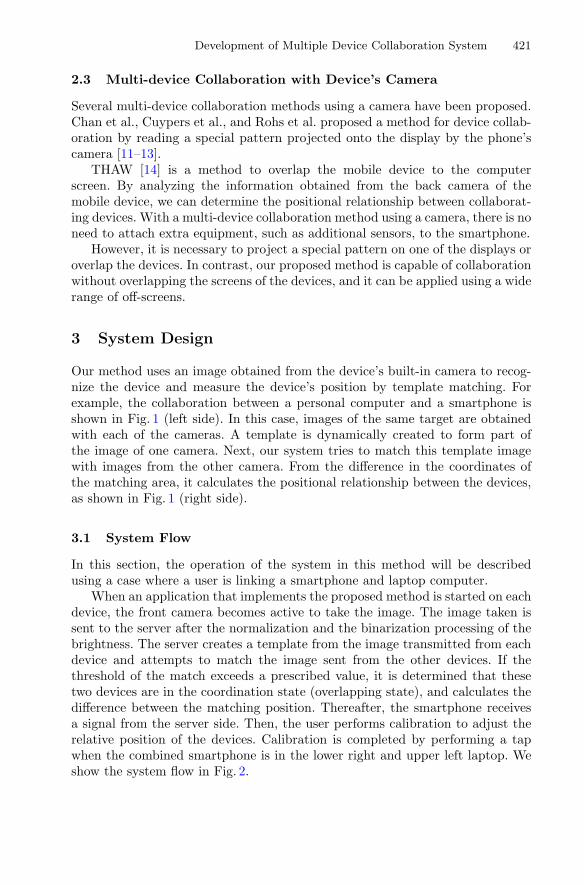
When an application that implements the proposed method is started on eachdevice, the front camera becomes active to take the image. The image taken issent to the server after the normalization and the binarization processing of thebrightness. The server creates a template from the image transmitted from eachdevice and attempts to match the image sent from the other devices. If thethreshold of the match exceeds a prescribed value, it is determined that thesetwo devices are in the coordination state (overlapping state), and calculates thedifference between the matching position. Thereafter, the smartphone receivesa signal from the server side. Then, the user performs calibration to adjust therelative position of the devices. Calibration is completed by performing a tapwhen the combined smartphone is in the lower right and upper left laptop. Weshow the system flow in Fig. 2.
422 K. Tada and J. Tanaka
Fig. 2. System flow
4 Implementation
For the implementation, we used an iPhone 5 and 13-inch Macbook Air. Thesoftware was developed using C++ (with openFrameworks). For data commu-nications between devices, we used HTTP for image processing for templatematching and OSC (open sound control) for send device coordinates. In addition,we used the SSD (sum of squared difference) method as the template matchingalgorithm.
Hereinafter, by using images obtained from two cameras, we describe themethods to calculate the positional relationship between devices.
4.1 Normalization of Resolution
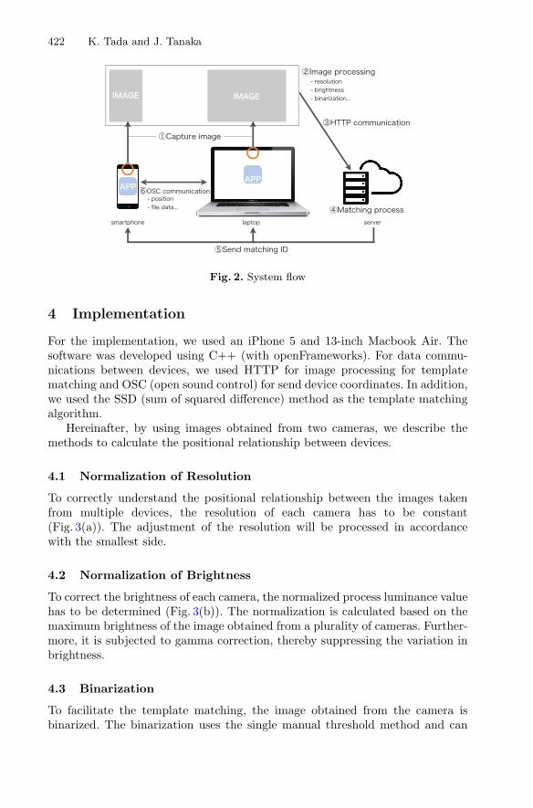
To correctly understand the positional relationship between the images takenfrom multiple devices, the resolution of each camera has to be constant(Fig. 3(a)). The adjustment of the resolution will be processed in accordancewith the smallest side.
4.2 Normalization of Brightness
To correct the brightness of each camera, the normalized process luminance valuehas to be determined (Fig. 3(b)). The normalization is calculated based on themaximum brightness of the image obtained from a plurality of cameras. Further-more, it is subjected to gamma correction, thereby suppressing the variation inbrightness.
4.3 Binarization
To facilitate the template matching, the image obtained from the camera isbinarized. The binarization uses the single manual threshold method and can
Development of Multiple Device Collaboration System 423
adjust the threshold value to suit the environment in which the coordination ismanually performed (Fig. 3(c)).
4.4 Making Template Image Dynamically
To generate the template image used for template matching, part of the videofrom one camera is extracted (Fig. 3(d)). The template image that shows thecenter of the object moving to the camera is automatically selected. For example,when the user is coordinating a laptop and smartphone, it is often the face ofthe person sitting in front of the laptop that is templated.
4.5 Matching Template Image with Other Images
Based on the template image generated using the previous technique, templatematching of the image obtained from each camera is performed. When the match-ing is performed, the positional relationship between devices is calculated usingthe difference in the matching area coordinates of the image obtained from thecamera (Fig. 1 left-side). The positional relationship is calculated by using thevalues of the calibration to be performed before collaboration and correction.
Fig. 3. Image processing algorithm
5 Applications
5.1 Translation Application
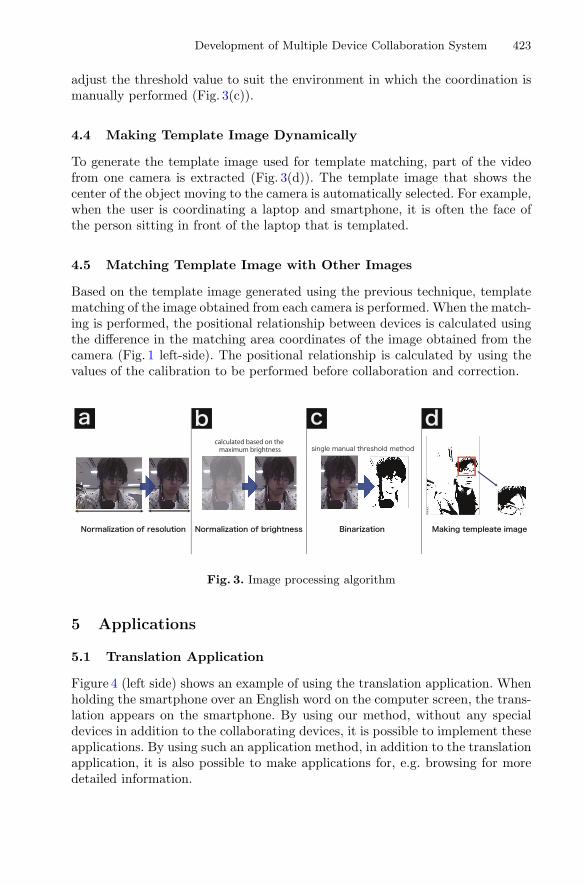
Figure 4 (left side) shows an example of using the translation application. Whenholding the smartphone over an English word on the computer screen, the trans-lation appears on the smartphone. By using our method, without any specialdevices in addition to the collaborating devices, it is possible to implement theseapplications. By using such an application method, in addition to the translationapplication, it is also possible to make applications for, e.g. browsing for moredetailed information.
424 K. Tada and J. Tanaka
5.2 Sub Display
Figure 4 (right side) shows an operational example of a screen sharing applicationusing device collaboration with our method. In this application, it is possible tomove the window on the screen of the personal computer to the smartphone.With conventional methods, the smartphone has to be superimposed on thescreen of the personal computer. By using our method, without reducing thedisplay area by covering the screen of the personal computer, it is easily possibleto use another device as an extended display.
Fig. 4. (a) Example of translation (English to Japanese) application, (b) Example ofscreen sharing application.
6 Experiment
We implemented the techniques described in the previous section and per-formed experiments in the two environments (laptop-smartphone and tablet-smartphone).
6.1 Experiment Outline
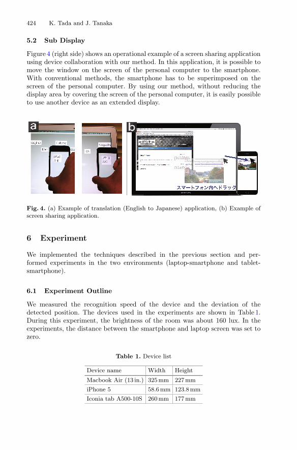
We measured the recognition speed of the device and the deviation of thedetected position. The devices used in the experiments are shown in Table 1.During this experiment, the brightness of the room was about 160 lux. In theexperiments, the distance between the smartphone and laptop screen was set tozero.
Table 1. Device list
Device name Width Height
Macbook Air (13 in.) 325mm 227mm
iPhone 5 58.6 mm 123.8 mm
Iconia tab A500-10S 260mm 177mm
Development of Multiple Device Collaboration System 425
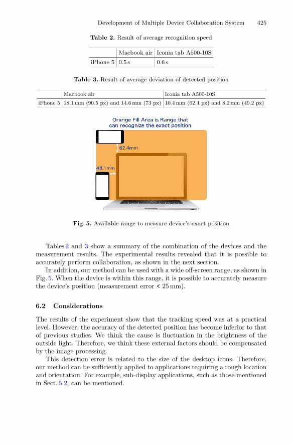
Table 2. Result of average recognition speed
Macbook air Iconia tab A500-10S
iPhone 5 0.5 s 0.6 s
Table 3. Result of average deviation of detected position
Macbook air Iconia tab A500-10S
iPhone 5 18.1mm (90.5 px) and 14.6mm (73 px) 10.4mm (62.4 px) and 8.2mm (49.2 px)
Fig. 5. Available range to measure device’s exact position
Tables 2 and 3 show a summary of the combination of the devices and themeasurement results. The experimental results revealed that it is possible toaccurately perform collaboration, as shown in the next section.
In addition, our method can be used with a wide off-screen range, as shown inFig. 5. When the device is within this range, it is possible to accurately measurethe device’s position (measurement error < 25 mm).
6.2 Considerations
The results of the experiment show that the tracking speed was at a practicallevel. However, the accuracy of the detected position has become inferior to thatof previous studies. We think the cause is fluctuation in the brightness of theoutside light. Therefore, we think these external factors should be compensatedby the image processing.
This detection error is related to the size of the desktop icons. Therefore,our method can be sufficiently applied to applications requiring a rough locationand orientation. For example, sub-display applications, such as those mentionedin Sect. 5.2, can be mentioned.
426 K. Tada and J. Tanaka
The most characteristic feature of this approach is that it can also cooperatein the off-screen. Therefore, we need to think of an example application thattakes advantage of this feature.
7 Conclusion
In this paper, we showed a multi-device collaboration system using an imageobtained from a built-in camera. This method is different from the existingapproaches in that it does not require a special device for collaboration. Weused the example of collaboration of a personal computer and smartphone andstudied the collaboration accuracy. In future work, we are planning to improvethe performance so that it can be adapted to big screens, such as table-topdevices. Moreover, we are planning to perform a user study of applications usingour technique.
References
1. Hiroki, K., Sugimoto, M., Yatani, K., Tamura, K., Hashizume, H.: Toss-it: intuitiveinformation transfer techniques for mobile devices. In: Proceedings of the SIGCHIConference on Human Factors in Computing Systems, CHI 2005, pp. 1881–1884(2005)
2. Kamo, H., Tanaka, J.: Interlocked surfaces: a dynamic multi-device collaborationsystem. In: The 15th International Conference on Human-Computer Interaction,HCII 2013, pp. 317–325 (2013)
3. Elstner, S., Hahne, U., Schild, J., Alexa, M.: Multi-touch focus+context sketch-based interaction. In: Proceedings of the 6th Eurographics Symposiumn Sketch-Based Interfaces and Modeling, SMIB 2009, pp. 77–83 (2009)
4. Dill, J.C., Swindells, C., Inkpen, K.M., Tory, M.: That one there! pointing toestablish device identity. In: Proceedings of the 15th Annual ACM symposium onUser Interface Software and Technology, UIST 2002, pp. 151–160 (2002)
5. Olwal, A., Lightsense: enabling spatially aware handheld interaction devices. In:Proceedings of the 5th IEEE and ACM International Symposium on Mixed andAugmented Reality, ISMAR 2006, pp. 119–122 (2006)
6. Sun, S.W., Cheng, W.H., Liu, K.W., Lin, I.P., Hsu, X.S.C.: G-spacing: a gyro sensorbased relative 3d space positioning scheme. In: Proceeding of ACM SIGGRAPH2015 Posters, SIGGRAPH 2015, Article No. 35 (2015)
7. Momeni, A., Xu, D., Brockmeyer, E.: Magpad: a near surface augmented readingsystem for physical paper and smartphone coupling. In: Proceedings of the 28thAnnual ACM Symposium on User Interface Software and Technology, UIST 2015,pp. 103–104 (2015)
8. Strohmeier, P.: Displaypointers- seamless cross-device interactions. In: Proceedingsof the 12th International Conference on Advances in Computer EntertainmentTechnology, ACE 2015, pp. 86–93 (2015)
9. Yasumoto, M., Teraoka, T.: Vistouch: dynamic three-dimensional connectionbetween multiple mobile devices. In: Proceedings of the 6th Augmented HumanInternational Conference, AH 2015, pp. 89–92 (2015)
Development of Multiple Device Collaboration System 427
10. Roudaut, A., Chan, L., Muller, S., Baudisch, P.: Capstones and zebrawidgets:sensing stacks of building blocks, dials and sliders on capacitive touch screens. In:Proceedings of the SIGCHI Conference on Human Factors in Computing Systems,CHI 2012, pp. 2189–2192 (2012)
11. Chan, L.W., Wu, H.T., Kao, H.S., Ko, J.C., Lin, H.R., Chen, M.Y., Hsu, J., Hung,Y.P.: Enabling beyond-surface interactions for interactive surface with an invisibleprojection. In: Proceedings of the 23th Annual ACM Symposium on User InterfaceSoftware and Technology, UIST 2010, pp. 263–272 (2010)
12. Vanaken, C., Reeth, F.V., Cuypers, T., Francken, Y., Bekaert, P.: Smartphonelocalization on interactive surfaces using the built-in camera. In: Proceedings ofthe IEEE International Workshop on Project-Camera Systems, Procam 2009, pp.61–68 (2009)
13. Raubal, M., Essl, G., Rohs, M., Schoning, H., Kruger, A.: Map navigation withmobile devices: virtual versus physical movement with and without visual con-text. In: Proceedings of the 9th International Conference on Multimodal Interfaces,ICMI 2007, pp. 146–153 (2007)
14. Heibeck, E., Maes, P., Leigh, S., Schoessler, P., Ishii, H.: Tangible interaction withsee-through augmentation for smartphones on computer screens. In: Proceedingsof the 27th Annual ACM Symposium on User Interface Software and Technology,UIST 2014, pp. 55–56 (2014)