Embed Size (px)
Citation preview
DEVELOPMENT OF LOW PROFILE UNIDIRECTIONAL ANTENNA FOR
WIRELESS LOCAL AREA NETWORK APPLICATION
LWAY FAISAL ABDULRAZAK
A project report submitted in partial fulfillment of the
requirements for the award of the degree of
Master of Electrical Engineering
(Electronics & Telecommunication)
Faculty of Electrical Engineering
Universiti Teknologi Malaysia
MAY 2007

iii
To
My beloved Mother, Father, Brothers
and to
The soul of my uncle Ahmed Dawod Alsuhayl
who devoted his life towards defending Islam and our country
iv
ACKNOWLEDGEMENT
First of all, Praise to Allah, the Most Gracious and Most Merciful, Who has
created the mankind with knowledge, wisdom and power.
I would like to take this opportunity to express my deepest gratitude to a
number of people who have provided me with invaluable help over the course of my
studies.
I thank Prof. Dr. Tharek Abd. Rahman, my supervisor, for his priceless help
and advice over the course of my research, and for reviewing this thesis. His wise
suggestions have always helped me and a great number of them have gone into the
thesis.
Special thanks are dedicated to the members of Wireless Communication
Center who offered invaluable technical assistance and supports, En. Mohamed Abu
Bakar, En. Omar bin Abdul Aziz, En. Mohammed Khomeini.
My sincere gratitude and thanks also goes to those who have contributed to
the completion of this research directly or indirectly.
v
ABSTRACT
This thesis will review the project conducted the development of a low
profile unidirectional antenna for WLAN applications, performed with frequency
range 2.4-2.4835GHz. The Radial Waveguide Slot Array Antenna (RWSA) is
investigated as a low profile, significant shape, lightly weight, simple but effective,
easy to design and fabricate with reasonable cost efficient. Simulation and
optimization of structure based on Zeland Fidelity - FDTD (Finite-Difference Time-
Domain) with Full-3D EM Simulation for the radiation pattern, and return loss. The
other part of this project deals with producing design relying on optimum simulation
results. The developed antenna was tested in terms of return loss, gain and radiation
pattern. Finally, integrated experimental trial had been compared with a monopole
antenna on an Access point for WLAN. Measurements are conformed to results
presented by the prototype simulation.
vi
ABSTRAK
Thesis ini akan mengulas project pembentukan antenna satu arah berprofil
rendah untuk aplikasi WLAN, dalam julat frekuensi antara 2.4-2.4835GHz. Antena
Radial Waveguide Slot Array (RWSA) telah didapati mempunyai rekabentuk yang
menarik dan ringkas, ringan, mudah dihasilkan, berkos rendah dan mempunyai nilai
gandaan yang tinggi. Simulasi dan optimasi struktur antena dilakukan menggonakan
perisian Zeland Fidelity - FDTD (Finite-Difference Time-Domain) dengan simulasi
Full-3D EM untuk menentukan corak radiasi dan nilai kehilangan balikan. Seterusn-
ya project ini telah menghasilkan rekabentuk antena RWSA berdasarkan hasil
simulasi yang paling optimum. Kehilangan balikan, gandaan dan juga corak radiasi
antena yang dihasilkan telah diukur dan dibandingkan dengan antena satu kutub bagi
aplikasi ‘Access point’ untuk WLAN. Pengukuran didapati bertepatan dengan hasil
simulasi yang diberikan oleh perisian Zeland Fidelity.

vii
CONTENTS
CHAPTER TITLE PAGE
TITLE i
DECLARATION ii
DEDICATION iii
ACKNOWLEDGEMENT iv
ABSTRACT v
ABSTRAK vi
CONTENTS vii
LIST OF TABLES xi
LIST OF FIGURES xii
LIST OF ABBREVIATIONS xv
LIST OF APPENDICES xvii
I INTRODUCTION
1.1 Introduction 1
1.2 Problem Statement 2
1.3 Objective 2
1.4 Research scope 3
1.5 Research Methodology 3
1.6 Thesis Outline 6

viii
II WIRELESS LOCAL AREA NETWORK AND
RADIAL WAVEGUIDE SLOT ARRAY ANTENNA
2.1 Introduction 7
2.2 Wireless LAN background 7
2.3 Indoor hot spot WLAN service and outdoor
last-mile broadband access 9
2.4 IEEE 802.11b/a/g Standards 11
2.5 Comparing the Wireless Standards 12
2.6 RWSA Evaluation 15
2.7 Introduction to RWSA 15
2.8 Single-Layer RWSA Antenna Design 18
2.9 Problem Configuration of RWSA 21
2.10 General Theoretical Consideration 22
2.10.1 Model of single slot 22
2.10.2 Model of slots’ assembly in radial line 23
2.11 Small RWSA Antenna 26
2.12 Summery 28
III RWSA ANTENNA DESIGN AND SIMULATION
MODELLING
3.1 Introduction 29
3.2 Antenna Structure 30
3.3 Initial Calculation Results 33
3.4 Finite Difference Time Domain (FDTD) Simulation 35
3.5 Antenna Simulation Modeling 37
3.6 Antenna Design and simulation results 40
3.7 Simulation results 41
3.8 Radiation pattern 41
3.9 Return loss Various Frequencies 42
3.10 Comparison between this design and previous
design 43
ix
3.11 Summary 44
IV FABRICATION AND MEASUREMENTS
4.1 Introduction 45
4.2 Antenna Prototype 45
4.3 Antenna Measurement Setup 48
4.4 Return Loss Measurement Result for the first
Design 48
4.5 RWSA 2.4 GHz Simulations and Prototype
(first design) Measurement Comparison 49
4.6 Second design 49
4.6.1 Introduction 49
4.6.2 Theoretical ideas and solutions 49
4.6.3 Second design structure 50
4.6.4 Comparison between the 1st & 2nd design 51
4.6.5 Return Loss Measurement Result for the
Second Design 52
4.6.6 Comparison between the First and the
Second design Parameters 52
4.6.7 Comparison between the RWSA second design and
4.6.8 the simulation results biases on the Return Loss 53
4.6.9 RWSA 2.4 GHz Simulations and Prototype
(Second Design) Measurement Comparison 53
4.7 Radiation pattern measurements 54
4.8 RWSA antenna Gain Result over deferent
Frequencies 56
4.9 Received Signal Strength Index 57
4.10 Summery 59

x
V CONCLUSION AND SUGGESTIONS FOR FUTURE
WORK
5.1 Conclusion 60
5.2 Suggestions for Further Work 61
REFERENCES 63
APPENDICES 66

xi
LIST OF TABLES
TABLES TITLE PAGE
2.1 802.11a vs. 802.11b vs. 802.11g 12
3.1 Initial calculation results based on 5.2 GHz antenna prototype 33
4.1 antenna parameters comparison for simulation and prototype for
First design 47
4.2 RWSA 2.4 GHz simulation and prototype measurement comparison 49
4.3 antenna parameters comparison for simulation and prototype 51
4.4 antenna parameters comparison for 1st & 2nd design prototype 51
4.5 RWSA 2.4 GHz simulation and prototype measurement comparison 54
xii
LIST OF FIGURES
FIGURES TITLE PAGE
1.1 Flow chart representing a unified design of RWSA antenna 5
2.1. a WLAN topology for ad-hoc mode 9
2.1. b WLAN topology for infrastructure mode 9
2.2 A circular slot formed by a multiplicity of short linear slots 16
2.3 Annular slot aperture and space geometry 16
2.4 Radial wavegide slot waveguide array (a) double layered, (b) single
layered 19
2.5 single layer RWSA with different feeds (a) probe feed, (b) recessed
cavity feed 20
2.6 Schematic presentation of the single-layered linear-polarized RWSA
antenna with its principal elements 21
2.7 Common slot geometry of linear-polarized RWSA antenna 22
2.8 equivalent electrical lumped-circuit model of slot in thin metallic plate 22
2.9 For the TEM two-plate guide 23
xiii
2.10 Ringed segment of radial line for its presentation by transmission
line model 24
2.11 Equivalent transmission line model of slots’ assembly in the radial guide
forming RWSA antenna aperture like quasi-periodic radial structure 25
2.12 Equivalent electrical features of slotted radial line where quality factor
Q as parameter above is determined by slot geometry namely 25
2.13 CP RWSA antenna proposed by Zagriatski and Bialkowski 27
3.1 R WSA antenna structure 30
3.2 The radiating surface of the RLSA antenna is formed by 4 discrete slots
arranged at tangent of the array radius 31
3.3 RLSA antenna structure shorted probe (lower layout) 32
3.4 Insertion of coaxial monopole SMA connector into the slotted radial
waveguide through the backing plate 32
3.5 Simulation domain in 3D outline view, which shows the antenna structure
and the space boundaries 38
3.6 Object list to define the antenna structure 39
3.7 3D view of the antenna structure, built in FIDELITY. The structure is
meshed into small rectangular cubes 40
3.8 Radiation pattern of the 2.4GHz RWSA antenna design 41
3.9 2.4GHz RWSA Antenna Radiation Pattern viewing from (a) z plane
and (b) y plane 42
xiv
3.10 Return loss in case of polypropylene as radial waveguide cavity 43
3.11 Comparison between this design and previous design [33] 43
4.1 The R WSA antenna prototype structure 46
4.2 Return loss result for R WSA first design antenna prototype 48
4.3 Return loss result for R WSA second design antenna prototype 52
4.4 Comparison between the First and the Second design Parameters 52
4.5 Return loss result Comparison between the second design and the
simulation results 53
4.6 direction of E-field, and the direction of H- field for the single slot 54
4.7 Rotating degree during the Radiation field pattern measurements at
00, 45o, and 90o 54
4.8 Radiation Pattern at 00 55
4.9 Radiation Pattern at 450 55
4.10 Radiation Pattern at 900 56
4.11 antenna gain under different frequencies 57
4.12 RSSI Comparison between RWSA antenna and RSSI of the monopole
antenna using AirMagnet for a short distance 58
4.13 Comparison between the RSSI of the RWSA antenna and RSSI of the
monopole antenna using AirMagnet for a Long distance 58

xv
LIST OF SYMBOLS
2D - Two dimension
3D - Three dimension
εeff - Effective dielectric constant
εo - dielectric constant of free space
εr - dielectric constant / permittivity
λ - wavelength
λg - guided wavelength
λo - free space wavelength
oμ - Permeability of free space
c - velocity of light
D - directivity
dB - decible
f - Frequency
b - Radial Cavity Hight
IL - Insertion Loss
L - Inductance
Pi - Incident Power
Pmax - Peak handling Capacity
Pr - Reflected Power
Pt - Transmited Power
R - Resistance
RL - Return Loss
TEM - Transverse Electromagnetic
V - Voltage

xvi
aρ - Slot Array Radius
scρ - Short circuit distance
wρ - waveguide radus
Ls - slot length
ws - slot width
Zo - chaecteristics impedance

xvii
LIST OF APPENDICES
APPENDIX TITLE PAGE
A Antenna Prototype Dimensions 65
B Antenna Measurement Setup 69
C RSSI SETUP 70
D Matlab Code for Radiation Pattern Graphs 71

CHAPTER I
INTRODUCTION
1.1 Introduction
Antenna designers are always searching for ways to improve existing designs
or introduce novel designs in order to achieve desirable radiation characteristics,
reduce the size and weight, which are mandatory requirement for antennas used in
WLAN and thus make antennas more cost efficient [1].
Return loss, axial ratio, gain, bandwidth and received signal strength are
some of the important properties which are improved.
The recent explosion in information technology and wireless communications
has created many opportunities for enhancing the performance of existing signal
transmission. An indispensable element of any wireless communication system is the
antenna. Transmission of data at higher rates requires adequate bandwidth for the
elements constituting a communication link accordant to IEEE802.11b/g standard
which well-handled in this project [2].
For WLAN applications, where problems such as multi-path fading due to
reflections from various scatters occur, a linearly polarized RWSA antenna is a
preferable option. The reason is that this polarization enhances overall system
diversity and permits freedom of orientation for the user-end antenna [3].

2
Radial waveguide slot array Antennas (RWSA) is very attractive for
applications in communication devices for wireless local area network (WLAN)
systems in the 2.4 GHz (2400–2484MHz), the free Industry-Scientific-Medicine
(ISM) frequency band [4]. Work investigated on development of the low profile
unidirectional Radial Waveguide Slot Array Antenna as a potential alternative to the
WLAN AP antenna.
1.2 Problem Statement
The problem statement of this project is stated in the follow: WLAN users
often complain of poor signal coverage. Therefore, an antenna with High gain and
directivity suitable for indoor and outdoor WLAN in 2.4GHz ISM band is required,
other point is the importance of obtaining a satisfactory coverage can not be over
emphasized.
Theoretical results are obtained to satisfy good return loss requirements and
specific radiation pattern shapes for the RWSA antenna, but the practical result is
still big challenge to be verificated and prove that down-to-earth.
1.3 Objective
The proposed project proposes a development of the low power profile for a
unidirectional antenna depending on Radial Waveguide Slot Array Antenna
(RWSA), which is attractive for point-to-multipoint point communications, linear
polarized small RWSA antenna as an external antenna for access point of WLAN
based on IEEE 802.11b/g standard, and the simulation design will done according to
the Federal Communication Commission (FCC) regulations, by depending on the
simulation results prototype will be doe and tested in Lab, and test bed as a field trial.
3
1.4 Research Scope
The Research introduces:
1. WLAN protocols such as IEEE 802.11a/b/g free ISM band for which RWSA
antennas are aimed to be designed.
2. The antenna specifications include parameters such as frequency, bandwidth,
polarization, gain and all theoretical investigations.
3. Following that the simulation tools for antenna design based on Zeland
Fidelity, FDTD, with Full-3D EM Simulation for the radiation pattern will be
introduced.
4. Using of the linear polarization to improve the antenna gain.
5. Simulation of the Radiation pattern until reach the best result, and compare
with previous design in field pattern and return loss result.
6. simulation result should be proven for indoor WLAN then outdoor WLAN
7. The prototype will be produced based on the simulation to involve the design
and development of the low profile antenna; it will be tested in Lab and test
bed as a field trial to measure the antenna performance.
8. Comparison of measured prototype with simulation.
9. Report / Thesis writing.
1.5 Research Methodology
A reactive theoretical and experimental design approach was utilized to
optimize the antenna structure, the strategy implemented for simplifying the design
and development procedures in this research work can be divided into the following
points:
1. initial concept
• literature review
• problem statement
• design conceptual understanding
4
2. Design and simulation stage
• Slot pattern design and desired radiation pattern and polarization.
• Antenna input impedance.
• Compare between this design and previous design.
3. Prototype stage
• Antenna fabrication.
4. Measurement stage.
• Radiation pattern.
• Return loss.
5. Analysis stage.
• Comparison between the measurements and the simulation results.
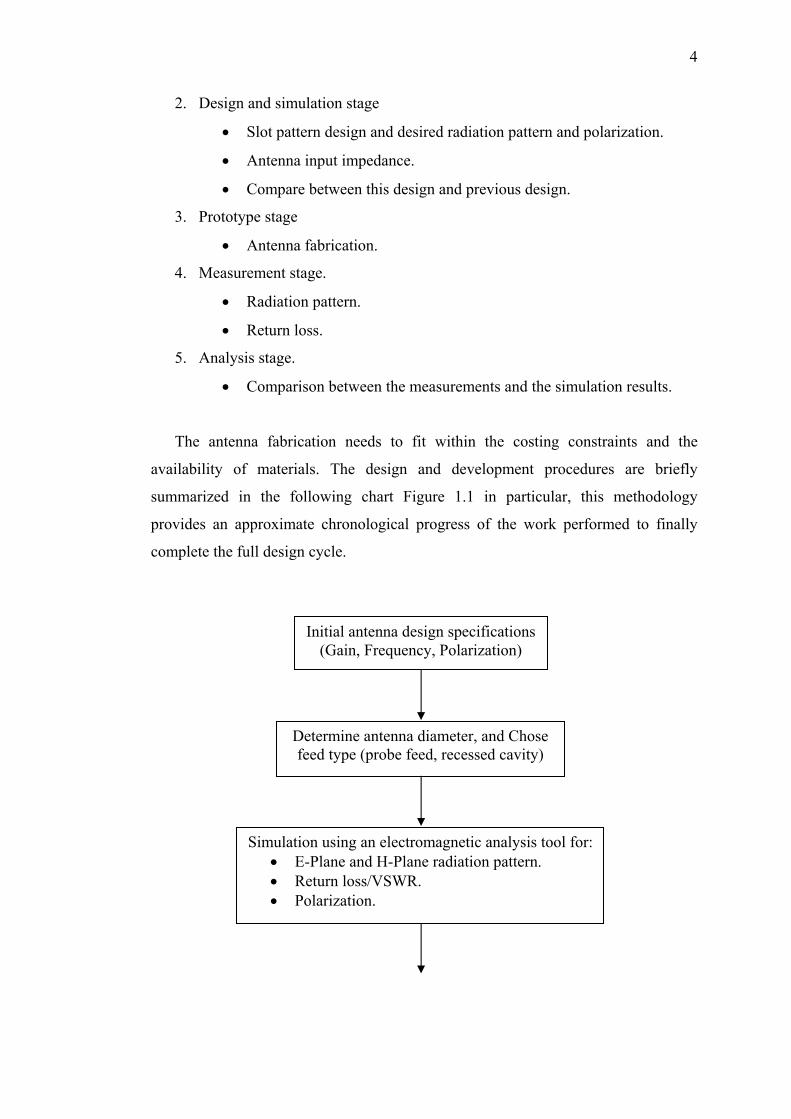
The antenna fabrication needs to fit within the costing constraints and the
availability of materials. The design and development procedures are briefly
summarized in the following chart Figure 1.1 in particular, this methodology
provides an approximate chronological progress of the work performed to finally
complete the full design cycle.
Initial antenna design specifications
(Gain, Frequency, Polarization)
Determine antenna diameter, and Chose feed type (probe feed, recessed cavity)
Simulation using an electromagnetic analysis tool for: • E-Plane and H-Plane radiation pattern. • Return loss/VSWR. • Polarization.

5
Generate slot pattern layout details
Model radiation pattern for obtained slot layout
Produce physical radiating surface and adhere to radial cavity
Suitable radiation pattern?
Perform experimental evaluation (return loss, gain, radiation, aperture profile)
Design specification
met?
No
Yes
Change offending parameters based on experimental
findings
No
Yes
Design complete!
Figure 1.1: Flow chart representing a unified design of RWSA antenna.

6
1.6 Thesis Outline
Chapter 1: Consists of introduction of the project. Brief General Background
is presented. The objectives of the project are clearly phased with detailed. The
research scope and methodology background are also presented.
Chapter 2: Includes section1 of the literature review, introduction to the
wireless communication, begins with an overview of indoor and outdoor contents
then IEEE standard. Radial Waveguide slot array antenna evaluation and general
description to the profile structure characteristics and its type also presented with
theory background, historical development.
Chapter 3: Design and simulation modeling for the antenna, provides
descriptions of the initial calculation results of the model and techniques for the finite
difference time domain, design and simulation results, compare the result with the
previous design.
Chapter 4: Presents the results of antenna prototype measurements and apply
the antenna in the real environment, starting with the indoor application then applied
the RWSA antenna outdoor.
Chapter 5: Concludes the thesis. The conclusion is given based on the
analysis of results from the previous chapter and suggestion for future research.