Embed Size (px)
Citation preview

“Studies on Radial Tipped Centrifugal Fan” 208
CHAPTER – 5
DEVELOPMENT OF FANS, TEST SET-UP AND EXPERIMENTAL MATRIX 5.1 Introduction
Experiments are the only means by which cause and effect can be established. It
allows for precise control of variables with which real performance characteristics of
any machine can truly be ascertained. The experimental method must consist of well
organized standard procedures and measures which allow it to be easily repeated and
form a sound base for validation of theoretical results.
It was clear from literature review that the number of blades [14, 31, 44] and slip
factor [22, 76] has remarkable influence on fan performance.
Eck Bruno [14], W. J. Kearton [25], states that the optimum number of blades
of a radial impeller can only be truly ascertained by experiments. Hence one of the
objectives of present work was to establish influence of number of blades on fan
performance by carrying out experiments under varying speed and varying flow
conditions.
For the proper design of centrifugal machines, it is essential to estimate the slip
factor correctly. Several co-relations as well as empirical equations are used in literature
for estimating the slip factor [9, 14, 75, 76, 78, 79, 83, 87]. Hence, experiments are also
planned to evaluate values of slip factor and to find out variation of slip factor along the
blade profile at different locations of volute casing, with two different impeller
geometries.
It is revealed from literature review that centrifugal fan design suggested by
different researchers differ widely. Therefore the performance of fans fabricated as per
individual and explicit design methodologies suggested by Church, Osborne and
retrieved from fundamental principles of fluid flow having minimum assumptions,
should be critically evaluated. Based on experimental results obtained, it is observed
that there exists a wide performance difference amongst fans under study. It concludes
that each design method, as an individual, is not performing as marked. It has also
revealed that there is a need to develop unified design methodology.

Chapter – 5: Development of Fans, Test Set-Up and Experimental Matrix
“Studies on Radial Tipped Centrifugal Fan” 209
In later stage, forward and backward curved radial tipped centrifugal fans are
fabricated as per proposed unified design methodology and their performance is
recorded by conducting experiments. Their results have clearly shown that fans based
on unified design are good enough to achieve desired performance. Major performance
parameters achieved are on higher side of design point.
Performance of centrifugal fan is highly affected by hydraulic, volumetric and
power losses [9, 28, 34]. Successful design methodology must be accompanied by
correct estimation of such losses which can give desired and designed performance.
The centrifugal fan, because of their relatively longer flow passages and greater turning
of flow, suffer higher losses compared to axial type [28]. Scope of experimental work
was extended towards experimental measurements of hydraulic, volumetric and power
losses occurring in flow passage of radial tipped centrifugal fan and henceforth to
improve suggested unified design methodology.
To achieve desired goals a systematical development of fans, test set up and
experimental matrix was planned in phase wise manner as follows:
Phase - I: Experimental Optimization of Finite Number of Blades under Varying
Speed Conditions
This phase is further sub divided in to two stages.
Stage 1: Influence of Suction Pressure on Performance of the Fan
Stage 2: Optimization of Finite Number of Blades
Phase - II: To evaluate the value of slip factor at Varying Number of Blades and
Speed Conditions as well as to check the effect of blade profile on Slip
Factor
Phase - III: Comparative Assessment of Explicit Design Methodologies.
Phase - IV: Performance Evaluation of Unified Design Methodology and
Comparative Performance Evaluation of Forward and Backward Curved
Radial Tipped Centrifugal Fan.
Phase - V: Assessment of Theoretical and Experimental Losses.
5.2 Phase Wise Development of Fans, Test Set-Up and Test Procedure
Each phase of study specifically requires a systematic development of fans, test
set up and test procedure relevant to set goals.

Chapter – 5: Development of Fans, Test Set-Up and Experimental Matrix
“Studies on Radial Tipped Centrifugal Fan” 210
Accordingly for each phase of study, the relevant fabrication of fans, its test set
up and test procedure has been systematically devised and presented in subsequent
sections.
5.2.1 Phase - I: Experimental optimization of finite number of blades under varying speed conditions The general design procedure is adopted as per the methodology outlined by Eck
Bruno [14]. It was streamlined by Bela Mishra [30]. Profile of the blade is designed as
per the methodology suggested by Austin Church [26]. The numbers of blades are
estimated as per the empirical formulas suggested by Eck Bruno, Pfleiaderer and
Stepanoff [9]. After calculating the optimum numbers of blades by empirical formulas,
they are verified experimentally in the steps of 8, 12, 16 and 24.
Transparent forward curved radial tipped centrifugal fan was fabricated from 3
mm and 4 mm acrylic sheets. Acrylic is a commercial name of poly methyl
methacrylate (PMMA) thermoplastic material. PMMA is in solid phase at room
temperature and it is fully transparent. It helps in better flow visualization and having
less coefficient of friction (which results in a thin boundary layer). The transition
temperature (Tg) of commercial grades of PMMA range from 85 to 165°C. Required
shape and profile from acrylic sheet is fabricated by cutting, heating and compression
molding methods. Heating, clamping and cooling are carried out such that stress
concentration and distortion can be avoided after cooling. To get exact geometrical
profile of parts, patterns/replicas are made from sheet metal or wood. Strong adhesives
and fasteners are used to join individual parts together to prepare leak proof assembly.
Finally, parts are machined to get required dimensions. Impeller is dynamically
balanced. Blades are fastened between front and back shroud plate in such a way that
number of blades can be varied in the steps of 8, 12, 16 and 24 without affecting
balancing. Impeller, suction duct and volute casing are also made from acrylic material
so that flow visualization is possible when coloured dust is mixed in flow streams to see
velocity vectors and flow stream lines. Acrylic material is brittle at room temperature
and possesses less impact strength and hence the fabrication work of this material is
challenging.
First stage of experiments was designed to study the influence of suction
pressure on performance of centrifugal fan. Second stage experiments were conducted

Chapter – 5: Development of Fans, Test Set-Up and Experimental Matrix
“Studies on Radial Tipped Centrifugal Fan” 211
to optimize finite number of blades under varying speed and suction pressure. Plate 5.1
shows transparent fan assembly fabricated for both stages of phase I experiments.
Plate 5.1 Transparent Fan Assembly for Phase I Experiments
The stage 1 of phase 1 is designed to study the influence of suction pressure on
performance of centrifugal fan. The design point parameters were 1150 Pa static stage
pressure rise at 0.417 m3/s volume flow rate and speed of impeller 2800 rpm. The
number of blades is varied in four steps of 8, 12, 16 and 24. The suction pressure is
varied with the help of orifice plates of different diameter. Suction pressure variation is
carried out by using six orifice plates of diameter 80, 90, 110, 120, 130,150 mm and full
opening of suction duct. Here, suction pressure variation lies in the range of 167 N/m2 to
1364 N/m2. These experiments have revealed that the orifice of 110 mm diameter offers
the design point stage pressure rise at optimum static efficiency.
The stage 2 of phase 1 is designed to find optimum number of blades at constant
suction pressure and under varying speed conditions. Number of blade is varied in four
steps of 8, 12, 16 and 24. During each set up of experiment, the performance parameters
are measured. To ascertain the optimisation process, the fan performance have been
evaluated under off design condition keeping the orifice of diameter 110 mm constant
and varying the speed of fan through variac. The results received during both stages of
this phase of experiments are discussed in detail in subsequent chapters. Following
formulas are used to calculate the test parameters. Sample calculations for phase 1
experiments are given in Annexure C.

Chapter – 5: Development of Fans, Test Set-Up and Experimental Matrix
“Studies on Radial Tipped Centrifugal Fan” 212
• √3 φ ,
Where φ = Power factor (which is assumed as 0.75)
•
(Efficiency of an induction motor is considered 80%)
• d 2 √ 2 m ρw/ρf 1
= 3.193 2 √ v
Where Pv = pressure head at vena-contracta of an orifice in m of H2O.
Cd = 0.62
• Stagnation pressure Po = Static pressure + velocity pressure ρ ν2 /2
• Air power = differential pressure head × discharge.
• Hydraulic efficiency ηhy = air power / shaft power.
Plate 5.2 shows experimental set up used for phase I experiments.
Plate 5.2 Experimental Setup for Phase I for Optimization of Finite Number of Blades
5.2.2 Phase - II: Experimental investigations on slip factor at varying number of
blades and speed conditions Another important factor influencing the designing of centrifugal fan is slip loss.
Slip loss is defined as the ratio of actual and ideal values of the whirl velocity
components at exit of impeller. It has significant effect on fan performance. It is
essential to estimate the slip factor correctly while designing centrifugal fans. During
literature survey, it is studied that several co-relations and empirical relations are used

Chapter – 5: Development of Fans, Test Set-Up and Experimental Matrix
“Studies on Radial Tipped Centrifugal Fan” 213
for estimating the slip factor. Analytical results of these relations differ widely for same
input data. Most of all concludes that the value of slip factor is constant and it is
dependent of impeller geometry only [31, 91]. However, fewer historical evidences and
experience has challenged this statement and have pointed that above statement is
partially correct and the slip factor not only depends on the geometry of the impeller but
also on the specific speed and flow rate [73]. Moreover, the value of slip factor does not
remain constant at any location at the exit from impeller blades.
The objective of this phase is to find experimental value of slip factor and effect
of number of blades on slip factor. In addition, work is carried out to check the effect of
volute location and blade width on slip factor. A specially designed, fabricated and
calibrated three hole pressure probe is used to sense optimum magnitude of actual static
pressure and total pressures at impeller exit. Pressure probe is mounted on the sliding
fixture which is having angular movement mechanism. So, the angular position of probe
can be varied to sense maximum velocity direction at optimum flow angle.
As per the basic requirement for the experimentation, the three hole pressure
probe is made from very small diameter surgical steel tubes (0.6 and 0.8mm ID, 1 and
1.5mm OD). Therefore variation and deviation in the flow velocity due to its insertion
within the flow region can be considered negligible. This three hole probe is very
sensitive to measure small amount of pressure at any test location. It is also able to
sense and determine the exact direction of flow. Probe is light in weight but highly rigid
and strong for sustaining the high flow pressures within the fan assembly.
Measurements of flow velocity at volute casing and at the centre of exit area
were made with Pitot tube and three hole pressure probe. This exercise was repeated for
all set of given number of blades. Static, total and dynamic pressure readings are
recorded. Velocity is calculated for known volute casing exit area of 0.010725 m2.
Table 5.1 shows velocity and discharge volume flow measurements done with Pitot
tube and three hole pressure probe. The difference in measurement leads to establish
coefficient of velocity measurement for three hole pressure probe. Thus, three hole
pressure probe is calibrated with standard pitot tube.

Chapter – 5: Development of Fans, Test Set-Up and Experimental Matrix
“Studies on Radial Tipped Centrifugal Fan” 214
Table 5.1 Three Hole Pressure Probe Calibration Readings
Number of Blades
Pitot Tube Readings Pressure Probe
Readings Coefficient of Velocity
CV
Average CV Velocity
in m/s Discharge
Velocity in m/s
Discharge
8 20.34 0.218 19.24 0.206 0.946
0.925 12 20.12 0.216 18.31 0.196 0.910 16 19.12 0.205 17.83 0.191 0.933 24 18.90 0.203 17.21 0.185 0.911
The experiments were carried out on centrifugal fan assembly used for phase I
with minor modifications. To calculate local slip factors one must have measured data
of actual velocity at that location. Measurements are made to find actual flow velocity,
static and total pressure at impeller exit and exit flow angles at various locations of
volute casing. Tapings are made in volute casing at 0˚, 30˚, 60˚, 90˚, 120˚, 150˚, 180˚
and 210˚. These tapings are shown by A,B,C...H test locations to take pressure
reading.The criteria that have to be taken into consideration while selecting the test-
locations are as under:
It must cover the maximum circumferential region of the impeller. Here
eight main test locations are selected (from A to H) as shown in
Plate 5.3.
Plate 5.3 Probe Insertion Test Locations
It must cover the total width of the impeller or blade in order to study the
effect of blade width on velocity profile as well as slip factor. Along the
width, seven sub-locations are selected for each main test locations.

Chapter – 5: Development of Fans, Test Set-Up and Experimental Matrix
“Studies on Radial Tipped Centrifugal Fan” 215
The gap between the probe and the circumference of the impeller must
be as minimum possible.
Table 5.2 shows test locations with notation to each sub location. Here test
locations are 8 while sub test locations are 56 in number.
Table 5.2 Notations of Probe Insertion Test Locations with Sub-Locations
Distance along the blade width (mm) → 0 15 30 37 45 60 75 1 2 3 4 5 6 7
Main locations along the circumference of the impeller Sub location points along the blade
width Degree. Main Location points
0 A A1 A2 A3 A4 A5 A6 A7 30 B B1 B2 B3 B4 B5 B6 B7 60 C C1 C2 C3 C4 C5 C6 C7 90 D D1 D2 D3 D4 D5 D6 D7 120 E E1 E2 E3 E4 E5 E6 E7 150 F F1 F2 F3 F4 F5 F6 F7 180 G G1 G2 G3 G4 G5 G6 G7 210 H H1 H2 H3 H4 H5 H6 H7
Probe can traverse axially along blade width to take seven different sub location
readings as per insertion location. Plate 5.4 and 5.5 shows three hole probe along with
measurement of static pressure at that location. Plate 5.6 shows probe gun assembly
used to change angular position of side tubes of probe.
Plate 5.4 Three Hole Probe for Velocity and Pressure Measurements

Chapter – 5: Development of Fans, Test Set-Up and Experimental Matrix
“Studies on Radial Tipped Centrifugal Fan” 216
Plate 5.5 Sketch of three hole probe Plate 5.6 Probe Gun Assembly
Plate 5.7 shows experimental setup with measurement instruments with axial
probe sliding and traversing arrangements.
Plate 5.7 Experimental Test Setup for Slip Factor Measurements for Phase II
Theoretical velocity diagram for radial tipped blade exit is prepared with the
help of theoretical values of tangential velocity component U2, radial velocity
component Vr2 and flow angle θ2. Actual velocity diagram is prepared with the help of

Chapter – 5: Development of Fans, Test Set-Up and Experimental Matrix
“Studies on Radial Tipped Centrifugal Fan” 217
measured components of absolute velocity V2’ at measured flow angle θ2
’ at impeller
exit.
The actual absolute velocity V2’ is measured with the help of probe while the
actual whirl angle is measured with the help of angular movement mechanism provided
on the sliding fixture. Theoretical component of tangential velocity U2 is also used to
construct actual velocity diagram. Actual component of radial velocity Vr2’ and actual
blade angle β2’ are received from actual velocity diagram. Construction of actual
velocity diagram is shown in Figure 5.1.
Figure 5.1 Impeller Exit Theoretical and Actual Velocity Triangles
From the above velocity diagram, whirl component of absolute velocity,
cos
Slip factor is defined as the ratio of actual to theoretical whirl components of
absolute velocities.
Slip factor μ / Vw2
Thus, experimentally, slip factor is calculated at all sub-locations for 8, 12, 16
and 24 number of blades. Slip factors of each test location is calculated by averaging
slip factor values of their sub-locations.
5.2.3 Phase - III: Comparative assessment of explicit design methodologies It is revealed from literature review that centrifugal fan design suggested by
different researchers differ widely. This phase of experimental work is planned for
experimental assessment of fan performance, fabricated as per individual and explicit

Chapter – 5: Development of Fans, Test Set-Up and Experimental Matrix
“Studies on Radial Tipped Centrifugal Fan” 218
design methodologies suggested by Church, Osborne and retrieved from fundamental
principles of fluid flow having minimum assumptions as discussed in chapter 3.
For this phase, Impeller, casing and test airway ducts are fabricated from 2 mm
thick mild steel sheets The forward curved radial tipped centrifugal fans are fabricated
as per the dimensions received after final iteration based on all three, i.e. fundamental,
Church and Osborne design methodologies. Fabrication work is carried out by using 14
gauge (2.03 mm) mild steel sheets. Impellers are double shrouded with 16 numbers of
blades as optimized by experiments of phase I. Inlet and discharge airway ducts are
fabricated as per IS 4894:1987 test standards. All impellers are made static and
dynamically balanced on balancing machine. Special templates are made to get desired
blade and casing profile. All joints are welded and proper care is taken to avoid
distortion. Volume flow variation dampers are used to change mass flow rates across
the fan. Arrangement is also made to lock the damper at various flow positions for
constant mass flow rate. Plate 5.8 to 5.11 shows impellers, casing and ducts fabricated
for phase III.
Plate 5.8 Impeller and Volute Casing as per Fundamental Design

Chapter – 5: Development of Fans, Test Set-Up and Experimental Matrix
“Studies on Radial Tipped Centrifugal Fan” 219
Plate 5.9 Impeller and Volute Casing as per Church Design
Plate 5.10 Impellers and Volute Casing as per Osborne Design

Chapter – 5: Development of Fans, Test Set-Up and Experimental Matrix
“Studies on Radial Tipped Centrifugal Fan” 220
Plate 5.11 Suction and Discharge Ducts as per IS Specifications
To get correct evaluation and performance of the fans, it is necessary to have a
very precise experimental set-up and instrumentation by which essential measurements
can be achieved with desired accuracy and reliability. These tests are conducted
according to standard test code IS: 4894-1987, Indian Standard Specification for
Centrifugal Fans (First Revision), Reaffirmed in 1994 [17]. Precise and calibrated
measuring and sensing instruments are used to measure flow, pressure, velocity, power
and rotational speed. Proper fixtures, supports and stands are used for sturdy and steady
setup. Basic experimental set up is similar for all phases and in accordance with IS
standard.
Three phase induction motor is used for impeller rotation. Variac is used to
change speed of rotation in the steps of 500, 1000, 1500, 2000, 2500 and 2800 rpm.
Ammeter, wattmeter and voltmeter are used for electrical measurements.
Observations are recorded for actual stage pressure head developed across the
fan, average air discharge, shaft power, airpower developed, static and stagnation
efficiencies for each centrifugal fan under study.
Based on experimental results obtained and evaluation made, it is recognized
that there exists a wide performance difference amongst fans under study. No fans are
performing as marked.
Chapter – 5: Development of Fans, Test Set-Up and Experimental Matrix
“Studies on Radial Tipped Centrifugal Fan” 221
5.2.4 Phase - IV: Unified design methodology and comparative performance
evaluation of forward and backward curved radial tipped centrifugal fan
Performance evaluation of experiments carried out under phase III has revealed
that all three explicit design methodologies are not performing as marked. It is observed
that there exists a wide performance difference amongst fans under study. It has
indicated a need to develop unified design methodology to get designed and desired fan
performance. Hence, successful outcomes of fundamental, Church and Osborne designs
are incorporated and unified design methodology for radial tipped centrifugal fan is
developed.
This phase of research work is planned for performance evaluation of forward
and backward curved impeller fans fabricated as per unified design methodology. All
the fabrication work is carried out from mild steel sheets. Scroll casing is designed and
fabricated as per four point method as described in chapter 3. The special templates and
fixtures are made for achieving desired blade profile and casing to avoid distortion after
welding. Impellers are dynamically balanced after fabrication. Tests are conducted
according to test code IS: 4894-1987. Plate 5.12 shows experimental test setup used for
phase IV.
Plate 5.12 Experimental Test Setup Used for Unified Design Methodology
Plate 5.13 to 5.17 shows fabrication details of blade profile, impeller in clamped
position, forward and backward curved radial tipped impellers, inlet and outlet ducts
and scroll casing, respectively.

Chapter – 5: Development of Fans, Test Set-Up and Experimental Matrix
“Studies on Radial Tipped Centrifugal Fan” 222
Plate 5.13 Unified Design Blade Profile
Plate 5.14 Unified Design FCRT Impeller Fabrications
Plate 5.15 Unified Design FCRT and BCRT Impellers

Chapter – 5: Development of Fans, Test Set-Up and Experimental Matrix
“Studies on Radial Tipped Centrifugal Fan” 223
Plate 5.16 Unified Design Suction Ducts
Plate 5.17 Unified Design Scroll Casing
5.2.5 Phase - V: Assessment of theoretical and experimental losses Overall efficiency of any machine depends on the various losses occurring in the
machine at different stages [9, 28 and 34]. There are various types of losses occurring
when the fluid passes from inlet duct to outlet duct of a turbo machine. The major losses
are classified into three categories as hydraulic or pressure losses, mechanical or power
losses and volume flow or leakage losses. Hydraulic losses reduce the available
pressure head developed by the impeller thereby reducing the Hydraulic efficiency.
Mechanical losses are mainly due to disc Friction and friction between rotating shaft
and the journal bearing. Leakage losses reduce the quantity of fluid delivered per unit
time and hence reduce the volumetric efficiency.
Performance of centrifugal fan is highly affected by hydraulic, volumetric and
power losses [9, 28 and 34]. Successful design methodology must be accompanied by

Chapter – 5: Development of Fans, Test Set-Up and Experimental Matrix
“Studies on Radial Tipped Centrifugal Fan” 224
correct estimation of such losses which can give desired and designed performance.
The centrifugal fan, because of their relatively longer flow passages and greater turning
of flow, suffer higher losses compared to axial type. Literature review on these losses
has exposed that loss estimation method proposed by different researchers differ widely.
Scope of experimental work under phase V was to make experimental
measurements of hydraulic, volumetric and power losses occurring in flow passage of
radial tipped centrifugal fan and henceforth to improve suggested unified design
methodology.
A separate fan assembly based on unified design methodology is fabricated for
0.159 m3/s designed flow rate with 456 Pa static stage pressure rise intended for loss
estimation and verification of slip factor. It is worth to mention over here that many
researchers have observed dependency of slip factor on impeller size and its geometry
volume flow, number of vanes and speed [9, 14, 75, 76, 79, 83 and 87]. Accordingly,
the measurements of slip factor in a different geometrical size of impeller were
undertaken here in.
Impeller is fabricated from mild steel while volute casing is fabricated from
transparent acrylic material for probe insertion and flow visualization. Plate 5.18 and
Plate 5.19 shows impeller and transparent casing fabricated for phase V experiments.
Plate 5.18 Radial Tipped Impeller

Chapter – 5: Development of Fans, Test Set-Up and Experimental Matrix
“Studies on Radial Tipped Centrifugal Fan” 225
Plate 5.19 Transparent casing
Velocity and pressure developed across the impeller and across the centrifugal
fan stage are measured with a developed and calibrated five hole pressure probe as per
G. L. Morrison [104] analysis technique.
Static, total and dynamic pressure readings are recorded. Velocity is calculated
for known volte casing exit area of 0.010286 m2. Readings are taken at the exit of the
centrifugal fan at a fully open position without damping. Table 5.3 shows velocity and
discharge volume flow measurements done with Pitot tube and five hole pressure probe.
The difference in measurement leads to establish coefficient of velocity measurement
for five hole pressure probe. Thus, five-hole pressure probe is calibrated with the help
of a standard pitot tube. Calibration of probe is essential to ensure the validity and
accuracy of measurements taken by it.
Table 5.3 Calibration of Five Hole Pressure Probe at 2800 rpm for Forward Curved Impeller Centrifugal Fan
Instrument Total pressure reading at outlet duct
Static pressure
Dynamic pressure
Velocity of fluid at outlet
10˚ Inclined
manometer mm of water
Vertical manometer
mm of water
N/m2 N/m2 N/m2 m/s
Pressure probe 202 35.07 340.00 211.7 128.30 14.84
Standard pitot tube 205 35.59 340.00 212 128.00 14.82

Chapter – 5: Development of Fans, Test Set-Up and Experimental Matrix
“Studies on Radial Tipped Centrifugal Fan” 226
Since the readings obtained by five-hole pressure probe and standard Pitot tube
are nearly equal, the value of velocity coefficient is one.
Plate 5.20 shows five hole pressure probe with its holding and traversing
mechanism. Plate 5.21 and 5.22 shows probe insertion locations and experimental set
up, respectively.
Plate 5.20 Five Hole Pressure Probe for Loss Analysis

Chapter – 5: Development of Fans, Test Set-Up and Experimental Matrix
“Studies on Radial Tipped Centrifugal Fan” 227
Plate 5.21 Probe Insertion Locations
Plate 5.22 Experimental Setup for Loss Analysis
5.3 Experimental Setup and Measurements
Fan testing includes measurements of airflow, pressure, power, and efficiency.
Fan performance curves can be developed from these measured data. All the fans
fabricated as per individual and unified design methodologies, are tested experimentally
to get their optimum performance. These tests are conducted according to standard test
code IS: 4894-1987, Indian Standard Specification for Centrifugal Fans (First
Chapter – 5: Development of Fans, Test Set-Up and Experimental Matrix
“Studies on Radial Tipped Centrifugal Fan” 228
Revision), Reaffirmed in 1994 [17]. Precise and calibrated measuring and sensing
instruments are used to measure flow, pressure, velocity, power and rotational speed.
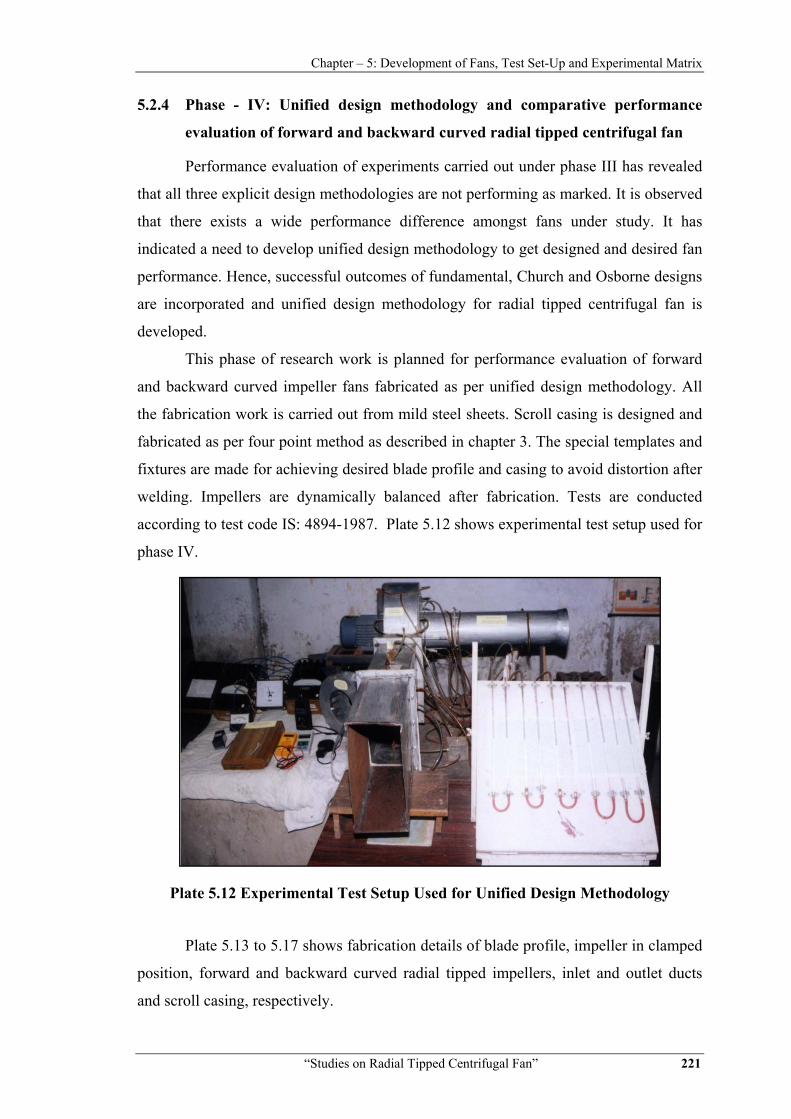
Proper fixtures, supports and stands are used for sturdy and steady setup. Basic
experimental set up is similar for all phases and in accordance with IS standard. Its line
diagram is shown in Figure 5.2.
Figure 5.2 Line Diagram of Experimental Setup as per IS 4894:1987
The various measurements and their instrumentation for experimental
investigations include:
• Pressure Measurement
For suction static pressure measurements in airway duct three section AA, BB
and CC are selected as per IS-Standard. At each section four co planner side tapings of
4.5 mm diameter are made as shown in Figure 5.2. Aluminium nipples of 30 mm length
are fitted at these side tapings. Tubes made of Poly-carbon material connect the nipples
of four side tapings and a square test box at each section. Square test box is used to
minimize effect of turbulence on static pressure measurements as well as to get average
pressure reading at a given section. Test box is connected to U-tube manometer as
shown in Figure 5.2 to measure average static pressure at section AA, BB and CC, in
terms of head of water column.
Similar way, static pressure distribution is measured at 90º, 120º, 180º, 240º,
300º and 360º tapings in volute casing as shown in line diagram. Atmospheric pressure
is verified with the help of laboratory aneroid barometer.

Chapter – 5: Development of Fans, Test Set-Up and Experimental Matrix
“Studies on Radial Tipped Centrifugal Fan” 229
• Speed Measurement
The number of revolutions of the motor shaft is measured by contact type digital
tachometer.
• Discharge Measurement
The velocity is measured at five different co-planer locations at outlet with the
help of digital anemometer. From these readings, average discharge velocity V4 and
thus discharge is calculated. This is also cross checked by measurement of static and
total pressure as described in IS 4894:1987.
• Electrical Measurement
The digital voltmeter and ammeter are used for voltage measurement across the
phase and current drawn, respectively. The power consumption is also measured by two
Wattmeter placed in series. Electrical circuit diagram is shown in Figure 5.3.
Figure 5.3 Electrical Circuit Line Diagram
Experimental setups are prepared for all five phases as per their standard
requirements.
Table 5.4 shows list of various instruments used for each phase of experimental
work.

Chapter – 5: Development of Fans, Test Set-Up and Experimental Matrix
“Studies on Radial Tipped Centrifugal Fan” 230
Table 5.4 Instrumentation Details
Sr. No.
Parameter Locations Instruments used
1 Static
pressure
Inlet duct, outlet duct, Impeller inlet, impeller outlet, volute outlet, clearance gap between impeller inlet and casing
Static pressure tapings and pressure
probe
2 Total
pressure Inlet duct, outlet duct, and impeller
outlet Five hole pressure
probe
3 Speed of rotation
Drive shaft Digital tachometer
4 Current Electric Motor Ammeter 5 Voltage Electric Motor Voltmeter 6 Power Electric Motor Wattmeter
5.4 Instrument Specifications
Table 5.5 shows list of instruments used for phase I to phase V experimental
measurements with their make, model number, least count, range and accuracy. Various
instruments are used for measurements of pressure, velocity and speed of rotation.
Electrical measurements of current, voltage and power are made to calculate input and
fan shaft power.
Table 5.5 Specifications of the Instruments used for Experiments
Sr. No.
Instruments Model
No. Make Range
Least Count
Accuracy
1 Digital
tachometer DT-
2235B Lutron
2.5 to 19,999 rpm
0.1 rpm ±0.05%
2 Digital
anemometer AM-4202
Lutron 0.4-30 m/s 0.1 ±1.0%
3 Digital Multi-
meter 603 Meco 0-750 V 1 V ±1.5%
4 Digital Multi-
meter 603 Meco
0-20 A
0.01 A
±2.0%
5 Analog
Wattmeter - AE 0-1500 W 5 W ±1.5%
6 AC Variac - AE 0-415 V 4 V

Chapter – 5: Development of Fans, Test Set-Up and Experimental Matrix
“Studies on Radial Tipped Centrifugal Fan” 231
5.5 Uncertainty Analysis
An uncertainty analysis is carried out according to Kline and Mclintock method
as compiled by Hollman J.P. [141] and given below in Table 5.6.
Table 5.6 Uncertainties in Measurements
Characteristic Uncertainty%
Input Power ±2.1
Stage Pressure Rise, Pa ±0.1
Volume Flow, m3/s ±1.5
Static Efficiency,% ±2.0
It is observed that all uncertainties in measurements are well within ± 5.0% of
design point values.